milling made easy with shopmill - siemens · pdf fileshopmill training documentation 1 faster...
TRANSCRIPT

SINUMERIK
SinuTrainMilling made easy with ShopMill
Training Documentation • 08/2006

4th and revised edition 08/2006Valid from software version V06.04
All rights reserved
Duplication or transmission of text, graphics or drawings in this document is prohibited unless express permission has been obtained in writing from the publisher. This also applies for duplication by photocopying or any other process includ-ing transfer to film, tape, disk, transparency or other media.
This Beginner’s Guide was produced in cooperation with Messrs.
SIEMENS AGAutomatisierungs- und AntriebstechnikMotion Control SystemsPostfach 3180, D-91050 Erlangen
and
R. & S. KELLER GmbH
Siegfried Keller, Stefan Nover, Klaus Reckermann, Olaf Anders, Kai Schmitz
Postfach 131663, D-42043 Wuppertal.
Order No.: 6FC5095-0AA50-0BP2

ShopMill Training Documentation
1
Faster from the drawing to the workpiece - but how?
Up to now, NC production mainly involved complicated, abstract, coded NC programming. Work that only specialists were able to carry out. However, every technical worker learns his trade and is able to put the experience gained in the area of conventional machining to use to cope with the most difficult tasks - even if the cost/benefit ratio often suffered gravely. A way had to be found to let these technical experts apply their knowledge effectively using NC machine tools.
This is why SIEMENS took a new approach with ShopMill, which saved the need for any coding on the part of the oper-ator. Instead, SIEMENS provides these technical experts with a new generation of SINUMERIK controls:
The solution here is to create a work plan rather than a program.
By creating a workplan with detailed operations of the kind a technician would carry out, the ShopMill user is able to apply his real expertise to the machining process, his actual know-how is not lost.
Even the most complicated of contours and workpieces can be produced easily with ShopMill thanks to the integrated, powerful traversing path creation function. The following therefore applies:
Move easier and faster from the drawing to the workpiece - with ShopMill!
Although ShopMill is really easy to learn, this ShopMill training course will introduce you to the new world even better. Before we start to work with ShopMill, we will address important fundamental issues in the first three chapters:
• First of all, we will outline the benefits of working with ShopMill.
• Then we shall demonstrate the basic operation to you.
• The geometrical and technological basics of production are then explained for newcomers in the chapter that follows.
Theory is followed by ShopMill practice:
• Five examples are used to explain the machining options offered by ShopMill; the complexity of the examples is increased continuously. At the outset, all the keys to be pressed are specified; later, you are prompted to act on your own.
• Then you are tought how to use ShopMill in automatic mode.
• If you wish, you can then test how fit you are in ShopMill.
Please note that the technology data used here can only be seen as examples, due to the numerous different conditions that apply in the workshop.
Just as ShopMill was produced with help from technicians, this training document was produced using input from practical users. In this vein. we wish you every success in your work with ShopMill.
The authors
Erlangen/Wuppertal, September 2003
Preface

ShopMill Training Documentation
Table of contents
1 Benefits of working with ShopMill ....................................................................51.1 You save training time … ................................................................................................. 51.2 You save programming time … ........................................................................................ 61.3 You save production time … ............................................................................................ 8
2 So that everything runs smoothly ....................................................................102.1 Tried-and-tested technology ........................................................................................... 102.2 The machine operator panel ............................................................................................ 112.3 Contents of the basic menu ............................................................................................. 13
3 Fundamentals for newcomers ..........................................................................183.1 Geometry basics .............................................................................................................. 18
3.1.1 Tool axes and work planes .................................................................................. 183.1.2 Points in the work area ........................................................................................ 203.1.3 Absolute and incremental dimensions ................................................................. 213.1.4 Movements on a straight line ............................................................................... 223.1.5 Circular movements ............................................................................................. 23
3.2 Technology fundamentals ............................................................................................... 243.2.1 Modern milling and drilling tools ........................................................................ 243.2.2 Tools used ............................................................................................................ 253.2.3 Cutting velocity and speeds ................................................................................. 263.2.4 Feed per tooth and feedrates ................................................................................ 27
4 Well equipped ....................................................................................................284.1 Tool management ............................................................................................................ 284.2 Tools used ....................................................................................................................... 304.3 Tools in the magazine ..................................................................................................... 314.4 Measuring tools ............................................................................................................... 314.5 Set the workpiece zero .................................................................................................... 32
5 Example 1: Longitudinal guide ........................................................................345.1 Program management and creating a program ............................................................... 355.2 Calling the tool, cutter radius correction and travel path input ....................................... 375.3 Creating holes and position repetitions .......................................................................... 39
6 Example 2: Injection form ...............................................................................426.1 Straight lines and circular paths via polar coordinates ................................................... 436.2 Rectangular pocket .......................................................................................................... 476.3 Circular pockets on a position pattern ............................................................................ 49
2

ShopMill Training Documentation
7 Example 3: Mold plate ......................................................................................517.1 Path milling for open contours ........................................................................................527.2 Stock removal, residual material and finishing of contour pockets ................................557.3 Machining on several planes ...........................................................................................597.4 Considering obstacles ......................................................................................................61
8 Example 4: Lever ..............................................................................................648.1 Face milling .....................................................................................................................658.2 Creating a border for the lever island ..............................................................................668.3 Producing the lever ..........................................................................................................678.4 Creating a border for the circular islands ........................................................................718.5 Creating a size-30 circular island ....................................................................................728.6 Creating a size-10 circular island ....................................................................................738.7 Copying the size-10 circular island .................................................................................748.8 Production of the circular island using the extended editor ...........................................758.9 Deep-hole drilling ............................................................................................................788.10 Helical milling .................................................................................................................798.11 Boring ..............................................................................................................................808.12 Thread cutting ..................................................................................................................818.13 Programming contours with polar coordinates ................................................................82
9 Example 5: Flange .............................................................................................849.1 Creating a subroutine .......................................................................................................859.2 Mirroring work steps .......................................................................................................899.3 Holes ................................................................................................................................929.4 Rotation of pockets ..........................................................................................................939.5 Chamfering contours .......................................................................................................989.6 Longitudinal groove and circumferential groove ............................................................99
10 So now we can start .........................................................................................10210.1 Approach reference point ..............................................................................................10210.2 Clamp the workpiece .....................................................................................................10310.3 Set the workpiece zero ...................................................................................................10310.4 Edit work plan ...............................................................................................................104
11 How fit are you with ShopMill? .....................................................................106
Index .................................................................................................................110Index of figures ................................................................................................113
3

4
ShopMill Training Documentation

ShopMill Training Documentation
This chapter states the special benefits of working with ShopMill.
… because there is no coding in ShopMill and no foreign-language terms that you must learn: All necessary inputs are queried in plain text.
…because you can also integrate DIN/ISO-SQL commands in the graphic work plan .
... because you can switch between the individual steps and the workpiece graphic at any time while producing a work plan.
1 Benefits of working with ShopMill
1.1 You save training time …
… because ShopMill provides colored help displays for your assistance. 1
5

1 Benefits of working with ShopMill
... because ShopMill provides optimum support while entering technology values: you only need to enter the following values from the book of tables: Feedrate/tooth and cutting speed - ShopMill automatically calculates the speed and the feedrate.
… because ShopMill can describe an entire machining step with one work step; and the necessary positioning movements (here from the tool change point to the workpiece and back) are gener-ated automatically.
… because the graphic work plan in ShopMill represents all machining steps in a compact and concise manner. This gives you a complete overview and provides enhanced editing options, even in the case of extensive production sequences.
... because several machining operations with numerous position patterns can be linked during drilling and do not have to be called repeatedly.
1.2 You save programming time …
6

ShopMill Training Documentation
… because the integrated contour calculator can handle all conceivable dimensions and is still easy to operate - thanks to the general-language input and graphic support.
... because you can toggle between the static help displays and dynamic on-line graphics at any time with just one key-stroke. The on-line graphic provides you with a direct means of visually checking the entered values.
… because the work plans Extensions and Finish are not mutually exclusive: With ShopMill you can create a new work plan in parallel with your production.
7

1 Benefits of working with ShopMill
… because you are not restricted by the radius of the pocket in your selec-tion of milling tools for machining contour pockets:The remaining residual material is detected and automatically machined by a smaller milling tool.
… because there are no superfluous infeed movements between the return and machining plane during positioning oper-ations. This is made possible by the settings Return on RP or Optimized return.
The setting Optimized return must be made in the program header by a technical expert. He must consider such obstacles as Clamping elements.
1.3 You save production time …
Residual material
Return on return plane (RP) Return on machining plane = time saving during production
Help displays in ShopMill1
8

ShopMill Training Documentation
... because you can utilize the compact structure of the work plan to optimize your machining sequence easily (here, for example, by saving tool change operations).
Original machining sequence
Optimized machining sequence through Cut and Paste for work steps
... because ShopMill makes full use of digital technology(SIMODRIVE drives, SINUMERIK controls) to achieve fastestfeedrates and highest accuracy for repeated operations.
9

2 So that everything runs smoothly
In this chapter, you learn the basics of how to operate ShopMill.
The SINUMERIK 810D as the basis for ShopMill is the most cost-effective way to get started in the world of future-proof, digital CNC and drives for machine tools.
With the aid of the SIEMENS three-phase servo motorsand ...
2
2
2
2
2
2
2
... SIEMENS gearbox technology, production is carried out attop speed, with the highest feedrates and with rapid traversingspeeds where required. 2
2 So that everything runs smoothly
2.1 Tried-and-tested technology
10
ShopMill Training Documentation
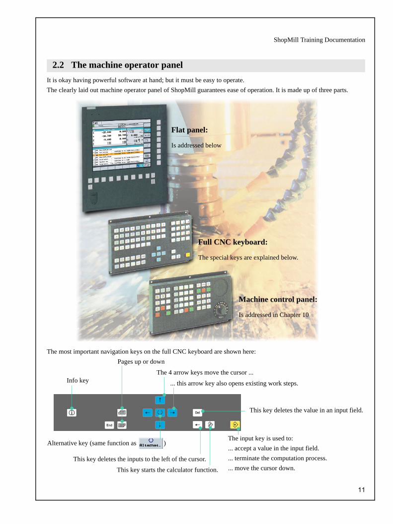
It is okay having powerful software at hand; but it must be easy to operate.The clearly laid out machine operator panel of ShopMill guarantees ease of operation. It is made up of three parts.
The most important navigation keys on the full CNC keyboard are shown here:
2.2 The machine operator panel
Full CNC keyboard:
The special keys are explained below.
Machine control panel:
Is addressed in Chapter 10
Flat panel:
Is addressed below
This key starts the calculator function.
The 4 arrow keys move the cursor ...
This key deletes the value in an input field.
This key deletes the inputs to the left of the cursor.
... this arrow key also opens existing work steps.
Alternative key (same function as )
Pages up or down
Info key
The input key is used to: ... accept a value in the input field.... terminate the computation process.... move the cursor down.
11

2 So that everything runs smoothly
Take a look at the different groups of keys on the panel; they help you get used to ShopMill.
Softkeys
The actual functional selection in ShopMill is car-ried out with the keys located around the screen. These are generally assigned directly to the relevant menu items. Since the contents of the menus change depending on the situation, we speak of softkeys.
All main functions can be called viathe horizontal softkeys.
2
All subfunctions of ShopMill are reached via the vertical softkeys.
2
The basic menu can be called at any time - irrespective of the particular operating step where you happen to be. 2
Basic menu 2
12

ShopMill Training Documentation
2
The machine is set up here, the tool traversed in manual mode, etc.You can also calibrate the tools and set zero points. 2
Enter a target position 2Calling a tool and entering technology values 2
2.3 Contents of the basic menu
During production, the current work step is displayed. You can switch to a parallel simulation per keystroke. While processing a work plan, you can add work steps or start to create a new work plan. 2
Display of work steps and current technology data ... 2
... or the simulation 2
13

2 So that everything runs smoothly
The work plans and contours are managed here. Furthermore, you can also input or output work plans.
To prevent a work plan list ecoming too long and difficult to handle, you can use the Program Manager to create as many directories as you like.
You can then save the various work plans in the different directories you have created.
The softkeys Continue and Back can be used at any time to switch back and forward between the softkey bars.
The selected work plan is processed in the Automatic machine mode.
Work plans are moved from the hard disk to the NC Kernel.
New folders and work plans are created.
Work plans are grouped together formoving or copying.
The marked work plans are placed on a clipboard.
The contents of the clip board is added to another folder.
The marked work plans or work steps are removed here and placed on the clipboard.
The work plans are exported to an external store. 2
Work plans are moved from the NC Kernel to the hard disk.
The work plans are imported from an external store.
Existing work plans are renamed.
Folders and work plans are renamed.
More than one workpiece can be machined in parallel.
Block transmission is possible toexecute long ISO programs.
14

ShopMill Training Documentation
2
Example for the interlinking of geometry and technology
This geometrical/technological link is clearly demonstrated in the graphical display of the work steps in the form of a "grouping" of the relevant icons. The "grouping" refers to a geometry/technology interlink.
Contour path milling
incl. approach and return strategies
Circular pocket incl. technology and position
Boring technology
Position for boring
Centering technology
Drilling technology
Positioning for centering and drilling
Contour
The work plan is created for the relevant workpiece here along with its full machining sequence. Prerequisite for the optimumsequence is the experience of the technician. 2
The contour to be machined is entered graphically... 2
Machining path milling
2
... and then converted to swarf: Geometry and technology are fully interlinked. 2
15

2 So that everything runs smoothly
As explained in Chapter 1, you can also input NC programs in foreign control languages in addition to the standardSINUMERIK programs. These commands are "understood" by ShopMill and converted to chips.
The ShopMill interface is based on the tried-and-tested Sinumerik 810D control. You can use the CNC ISO to switch to the Sinumerik plane. The production can now run in exactly the same way as the other 810D controls. 2
The combination of ShopMill with the Sinumerik 810D produces high flexibility in the CNC production. 2
A dedicated Getting Started Guide (Order No. 6FC5095-0AB00-0BP1) with two sample programs for milling workpieces is available for the G code programming of the 810D/840D. 2
N90 G291 (selection of the external language) 2
N100 G17 G54 Plane selection and zero point offset 2
N105 G90 G00 G43 X0 Y0 H1 Z100 ... 2
N110 G83 X10 Y11 Z-30 R10 F100 Q8 Drilling cycles with the control-related parameters 2
N120 X80 Y90 Drilling position 2
N130 G80 End of drilling cycles 2
N140 G53 X20 Y20... 2
N150 G55... 2
N160 G290 (back to SINUMERIK language) 2
16

ShopMill Training Documentation
All currently present messages and alarms are displayed with the corresponding error number, the time at which the error occurred and further details of the particular error.
A list of messages and alarms is given in the ShopMill user documentation.
The zero points are saved in a clearly laid outtable of zero points.
No stock removal without tools. You can manage these in a tool list ...
... and combine them in a magazine.
17

3 Fundamentals for newcomers
All the fundamentals of the geometry and technology for milling are explained in this chapter.No entries have been made in ShopMill yet.
3.1.1 Tool axes and work planes
The tool can be installed in parallel to each of the three main axes on universal milling machines. These axes which stand at right angles to each other are oriented according to DIN 66217 or ISO 841 on the main guide ways of the machine.
The installation position of the tool produces a corresponding work plane. Z is usually the tool axis.
Tool axis Z
3 Fundamentals for newcomers
3.1 Geometry basics
Vertical spindle
Horizontal spindle
On modern machines, it only takes a few seconds to change the tool mounting position with a universal revolver and there is no need for conversion work. 3
18

ShopMill Training Documentation
If the coordinate system on the previous page is rotated appropriately, the axes and their directions are changed in the corresponding work planes (DIN 66217).
Tool axis X
The figure shows the program header after switching to tool axis X.
Tool axis Y
You can of course use the key to call a help display to help you select the tool axis and enter the values in the program header.
19

3 Fundamentals for newcomers
3.1.2 Points in the work area
For orientation of a CNC control (like the SINUMERIK 810D with ShopMill) over the measuring system in the existingwork area, important reference points must be defined.
Machine zero M
The machine zero M is defined by the manufacturer and cannot be changed. It lies in the origin of the machine coordinate system.
Workpiece zero W
The workpiece zero W is also referred to as the program zero and is the origin of the workpiece coordinate system. It can be selected freely and should be positioned at the point in the drawing where most dimen-sions originate.
Reference point R
The reference point R is approached to set the measuring system to zero, since the machine zero generally cannot be approached. In this way, the control finds its starting point for counting in the linear measure-ment system.
20

ShopMill Training Documentation
3.1.3 Absolute and incremental dimensions
Here are some examples for the combination of absolute/incremental values:
Absolute entry:The input values refer to the workpiece zero.
Incremental inputs:The input values refer to the starting point.
3
You can use the key to switch over at any time. 3
End point
Starting point
End point
Starting point
For absolute inputs, you must always enter the absolute coordinate values of the end point (the start point is not considered).
For incremental inputs, you must always consider the direction when entering the difference values between start point and end point.
Absolute: X-10 Y-5Incremental: X30 Y25
Absolute: X-30 Y50Incremental: X-15 Y40
Absolute: X15 Y5Incremental: X-35 Y-25
21
3 Fundamentals for newcomers
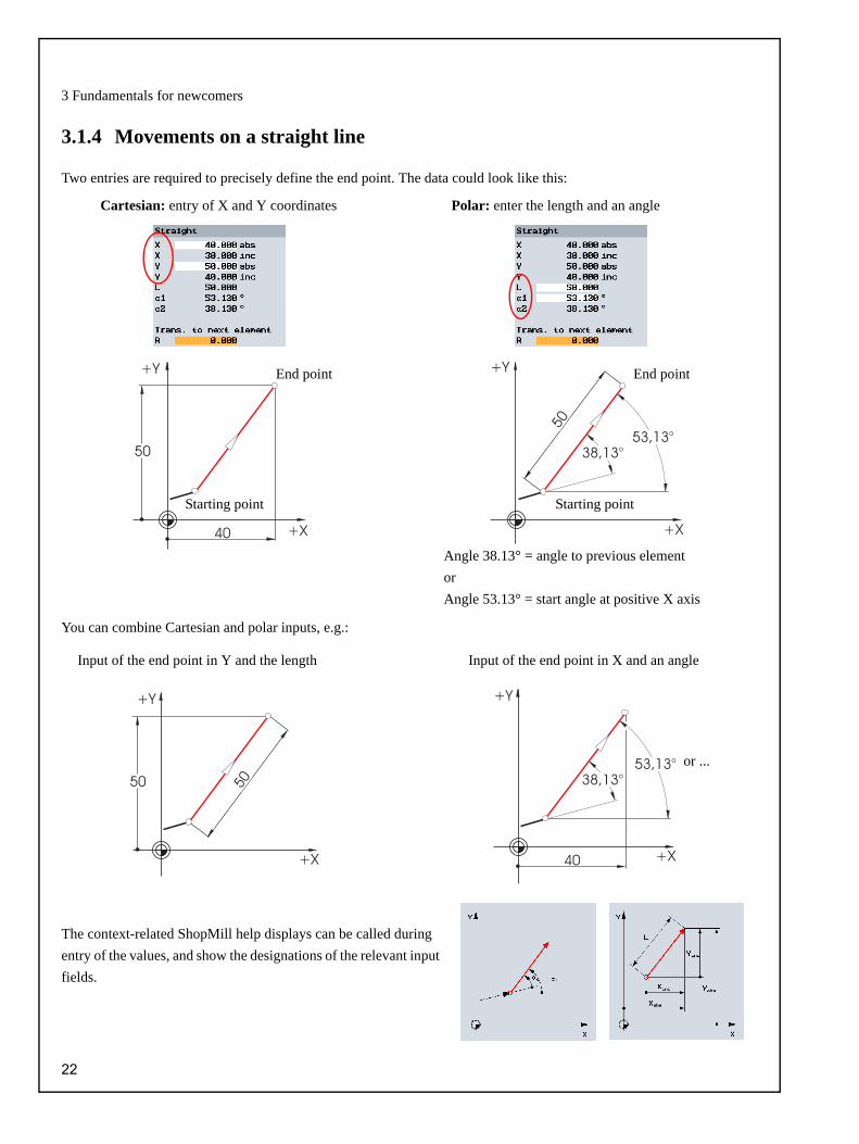
3.1.4 Movements on a straight line
Two entries are required to precisely define the end point. The data could look like this:
You can combine Cartesian and polar inputs, e.g.:
The context-related ShopMill help displays can be called during entry of the values, and show the designations of the relevant input fields.
Cartesian: entry of X and Y coordinates Polar: enter the length and an angle
End point End point
Starting point Starting point
Angle 38.13° = angle to previous elementorAngle 53.13° = start angle at positive X axis 3
Input of the end point in X and an angleInput of the end point in Y and the length
or ...
22

ShopMill Training Documentation
3.1.5 Circular movements
X and Y define the end point for the circular arc; the center point is entered with I and J. In ShopMill, you can enter these 4 values individually, either as absolute or incremental values.
Whereas X and Y are entered as absolute, the center point I and J are entered as incremental for most controls. Here, it is essential not only to determine the difference from the starting point A to the center point M (often in combination with mathematical computation), but also the direction and thus the sign.
With ShopMill on the other hand, you do not have to perform any calculation because you can enter the absolute center point; you can use the contour calculator to determine even the most complex contours graphically.
Entering the center point (absolute):
ShopMill also enables you to display all possible geometry values:
Display of all parameters:
A further benefit of the absolute center point dimensioning: You do not have to recalculate the values for I and J when you reverse the milling direction.
After input: 3 After input: 3
Values (in this case radii) that result from data already entered are computed automatically by ShopMill. 3
23

3 Fundamentals for newcomers
The basic requirements for optimized production are a sound knowledge of the tools (especially the cutting materials of the tools), the tool applications and the optimum cutting data.
3.2.1 Modern milling and drilling tools
Whereas HSS tool steels were dominant in the past, hard metals, ceramic plates, cubic bornitride (CBN) plates and poly-crystalline diamond tools are used today. The following diagram shows the percentage distribution of the cutting materials and their properties, relative to their toughness and durability. 3
3.2 Technology fundamentals
Non-coated tools made of HSS
Tools with sintered cutting plates
The diagram is taken from a SANDVIK tool catalog. The newly developed carbide materials which combine toughness and durability to produce high productivity values are also listed. Such cutting materials also bring the following bene-fits: longer tool life and better surface qualities.
Titan nitride (TiN)- coated drilling and milling tools
24
ShopMill Training Documentation
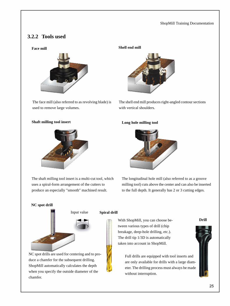
3.2.2 Tools used
Face mill Shell end mill
The face mill (also referred to as revolving blade) is used to remove large volumes. 3
The shell end mill produces right-angled contour sections with vertical shoulders. 3
Shaft milling tool insert Long hole milling tool
The shaft milling tool insert is a multi-cut tool, which uses a spiral-form arrangement of the cutters to produce an especially "smooth" machined result. 3
The longitudinal hole mill (also referred to as a groove milling tool) cuts above the center and can also be inserted to the full depth. It generally has 2 or 3 cutting edges. 3
NC spot drills are used for centering and to pro-duce a chamfer for the subsequent drilling. ShopMill automatically calculates the depth when you specify the outside diameter of the chamfer. 3
Spiral drill
Drill
NC spot drill
With ShopMill, you can choose be-tween various types of drill (chip breakage, deep-hole drilling, etc.). The drill tip 1/3D is automatically taken into account in ShopMill. 3
Full drills are equipped with tool inserts and are only available for drills with a large diam-eter. The drilling process must always be made without interruption. 3
Input value
25

3 Fundamentals for newcomers
3.2.3 Cutting velocity and speeds
The optimum speed of the tool in each case depends on the cutter material and the workpiece material, as well as the work-piece diameter. You can often enter this speed on the basis of year-long experience, without calculation. However, it is better to calculate the speed from the cutting velocity given in the tables.
Determining the cutting velocity:
The manufacturer’s catalog or a book of tables helps you to determine the optimum cutting velocity initially.
This cutting velocity and the known tool diameter is used to compute the speed n.
In the example below, the speed is computed for two tools:
The speed is specified with the letter S (for speed) in the NC coding. So the inputs are as follows:
Material of the tool:
Hard metal
Material of the workpiece:
C45%
vc = 80 - 150 m/min:The mean value vc = 115 m/min is selected
n vc 1000⋅d π⋅
----------------------=
d1 = 40mm d2 = 63mm
n1 900 1min---------≈ n2 580 1
min---------≈
n1115mm 1000⋅40mm π min⋅ ⋅-------------------------------------= n2
115mm 1000⋅63mm π min⋅ ⋅-------------------------------------=
S900 S580
26
ShopMill Training Documentation
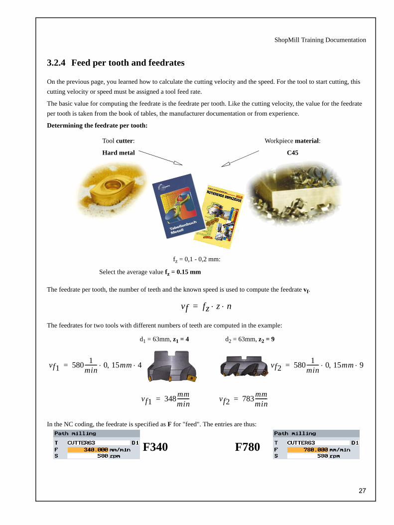
3.2.4 Feed per tooth and feedrates
On the previous page, you learned how to calculate the cutting velocity and the speed. For the tool to start cutting, this cutting velocity or speed must be assigned a tool feed rate.
The basic value for computing the feedrate is the feedrate per tooth. Like the cutting velocity, the value for the feedrate per tooth is taken from the book of tables, the manufacturer documentation or from experience.
Determining the feedrate per tooth:
The feedrate per tooth, the number of teeth and the known speed is used to compute the feedrate vf.
The feedrates for two tools with different numbers of teeth are computed in the example:
In the NC coding, the feedrate is specified as F for "feed". The entries are thus:
Tool cutter:
Hard metal
Workpiece material:
C45
fz = 0,1 - 0,2 mm:
Select the average value fz = 0.15 mm
vf fz z n⋅ ⋅=
vf1 580 1min--------- 0 15mm, 4⋅ ⋅= vf2 580 1
min--------- 0 15mm, 9⋅ ⋅=
vf1 348 mmmin---------= vf2 783 mm
min---------=
d1 = 63mm, z1 = 4 d2 = 63mm, z2 = 9
F340 F780
27

4 Well equipped
In this chapter, you learn how to create tools for the examples in the chapters that follow. An explanation is also given on how to compute typical workpiece lengths and how to set the workpiece zero.
ShopMill offers three lists for tool management.
1. Tool list
All the tools and associated offset data in the NC are specified and displayed here, irrespective of whether the tools are assigned to a magazine location.
4 Well equipped
4.1 Tool management
Numerous tool types are available. There are various geometry parame-ters for each tool type (e.g. specified angle for drilling). 4
The tool name is suggested automat-ically on the basis of the selected tool type. This name may be changed as required but must notexceed a length of 17 characters. All letters, number and underscores are permitted. 4
Length of the tool 4
Tool diameter 4
Since it is also possible to enter thefeedrate/tooth in ShopMill, the number of teeth must also be specified. 4
Acute angle of tool 4
Direction of the tool 4
Used to activate/deactivate coolant feeds 1 and 2 4
Further tool-specific functions such as speed monitoring or tool break monitoring 4
DP = Duplo number (a sister tool of the same name is created here) 4
28

ShopMill Training Documentation
2. Tool wear list
You define the tool wear data for the relevant tools here.
3. Magazine list
The magazine list contains all the tools that are assigned to one or more tool magazine(s). This list shows the status of each tool. Magazine positions can also be reserved or locked for particular tools.
You can use this toggle fields to define thefollowing properties: 4
1. Lock tool
2. Oversize tool
3. Tool to fixed location
You enter the tool wear here, relative to the dif-ference values for the tool length and the tool diameter.
You define the tool monitoring here, relative to the tool life or the number of tool changes. T monitors the tool life, C the number of tool changes.
You specify the life in minutes here, provided that you have activated the function (T) previously.
You enter the number of tool changes here, provided that you have activated this function (C) previously.
The current tool status is shown here. 4
The location lock is activated here. 4
29

4 Well equipped
In this chapter, you enter the tools required later for machining in the examples in the tool list.
Create tool
4.2 Tools used
Select tool type and enter data
... find empty location
Note: The milling tools with diameters 6, 10, 20 and 32 must be capable ofbeing inserted because they are also used to mill pockets in the following examples. 4
30

ShopMill Training Documentation
In the following sections, you learn how to insert tools in the magazine.
Select a tool from the tool list without location number and press the key .
The following dialog offers the first free magazine location which you may change or accept as offered.
The magazine for the following exercises could look like this.
In the following, you will learn how the tools are calculated
Load a tool into the spindle using softkey . Change to the menu .
4.3 Tools in the magazine
4.4 Measuring tools
The tool is measured in the Z direction using the function Length manual.
The tool diameter is measured using the function Diameter manual.
The tool is measured in the Z direction by means of a tool gauging device using the function Length auto.
The diameter of the tool is measured by means of a tool gauging device using the function Diam. auto.
The tool length and tool diameter are measured automatically using the func-tion Calibrate Probe.
31

4 Well equipped
To set the workpiece zero, you must switch to the Manual machine mode in the basic menu.
The option Meas. workp. in the submenu providesseveral options for setting the workpiece zero.
The example shows how to set the zero point of a workpiece edge ( ) with an edge probe.
Procedure:
1.
2. Select the edge
(the help display shows the necessary clickingdirection).
3. Click the workpiece edge
4.
The workpiece zero is set, taking account of the edge probe diame-ter (4 mm).
This procedure must now be repeated for Y with the edge probe and for Z (usually with the milling tool).
4.5 Set the workpiece zero
This key calls the list of zero offsets, which can then be set in the Zero offset field.
Enter a zero offset
Clicking directionleft (+) or right (-)
Shift the workpiece zero offset if it is not to lie at theedge of the workpiece
32

ShopMill Training Documentation
Since the workpieces to be machined are not always present in the form of a cuboid or cannot be clamped in straight, further computation options are available:
If such a workpiece position is the case, the workpiece position/corner can be determined by approaching the four points.
Considering a hole or a spigot:
When you insert an electronic 3D probe from the tool magazine, clamping tolerances apply. These would falsify the results in further measurements. To prevent this happening, you can use the Calibrate probe cycle for the 3D probe on any ref-erence surface or in any reference hole for calibration purposes.
3D probes are available in electronic and mechanical
designs. The signals of the electronic probe can be pro-
cessed directly by the control.
33

5 Example 1: Longitudinal guide
In this chapter, we will take a detailed look at the first steps required to create a workpiece:
• Program management and creating a program
• Calling the tool and chamfer radius offset
• Entering the traversing path
• Producing holes and position repetitions
5 Example 1: Longitudinal guide
Note: Since ShopMill always saves the last setting set via the key or the softkey , you must make sure that all the units, texts and symbols are set as displayed in the dialog boxes shown for all the examples both for numerous of the input fields and for all toggle fields.The switchover option can always be identified by the sofkey that is visible. 5
34

ShopMill Training Documentation
Keys Screen Explanations
• In the basic menu, you can call the various areas of ShopMill (see Chapter 2).
• In the program manager a list of the available ShopMill directories is shown.
W...• A new directory is created to save the work
plans in the next chapter. It is given the name "Workpieces".
• The work plan and contour management is organized in the program manager (e.g. New, Open, Copy ...).
• You can use to move the cursor to the WORKPIECES directory and the key to open it.
L...
• The name of the work plan is entered here, in this case "Longitudinal guide".
• You can use to accept the name.
• The softkeys ShopMill program and G code program can also be used to select the input format.
1-75-50
0
• The workpiece data and the general data about the program are entered in the program header.
• Since the zero of the workpiece lies in the center of the workpiece surface, the coordi-nates of the left-hand workpiece corner have a negative value.
• You can use the key to call the helpdisplays at any time.
5.1 Program management and creating a program
...5
35

5 Example 1: Longitudinal guide
The program has now been created as the basis for further machining steps.
It has a name, a program header (abbreviated by the "P") and a program end (designated by the symbol "END").
The relevant machining steps and contours are stored one below the other in the program. Processing later is carried out from top to bottom.
150100-20
• You can use the key to toggle between inputting the Corner point 2 and Deviations.
• The setting Deviations is selected here so that the dimensions of the unmachined part can be entered directly (when entering the height, you must pay attention to the sign).
• With the key switch back to on-line graphic.
22x
• You can also specify the Retract plane, the Safety distance, the Machining sense (syn-chronism or in opposite direction) and the Return for position patterns in the program header.
• The position pattern can be set to optimized( = time-optimized travel paths) or on return plane.
• The key means that all values in the dialog window are accepted.
• The program header created is marked with the pictogram P.
• You can use to re-call the program header to make a change, for example.
Optimized return (optimal)
The tool returns on the return plane and feeds at the new position.
The tool returns over the workpiece at the safety clearance as appropriate to the contour.
On the return plane (standard)
Help displays fromShopMill 5
36

ShopMill Training Documentation
Explanations for the topic radius offset:
• The size-60 milling tool is selected from the tool list and accepted.
• You must press the key repeatedly until the red cursor is positioned at the relevant tool.
80• When you have selected the tool you must
change the cutting speed as necessary in the input field (80 m/min).
1100
2x3x
• The value X is 75 mm + 30 mm + clearance.
• The radius offset is deactivated.
Alternative settings in this field:
- Previous offset setting(symbolizes an empty field)
- To the left of the contour in the direction of milling
- to the right of the contour in the direction of milling
5.2 Calling the tool, cutter radius correction and travel path input
...5
Just imagine that the milling tool were to approach the center point on the contour that has been created:
Tool corrected
Tool not corrected= scrap
Tool to the left of the contour
Tool to the right of the contour
37

5 Example 1: Longitudinal guide
2x-10
• The tool is positioned in Z.
-1102x
400
• Enter the first machining path up to X -110
• At F, the system switches over to mm/min.
• The workstep list looks like this after thedialog is accepted:
• Now change the next tool on your own (CUTTER16, V 100 m/min).
• Then create the travel paths to be entered in the work plan below.
• The simulation is started with
• In the following examples, the simulation can also be called when it is not shown explicitly.
• Further information is given at the end of Chapter 7.
• The simulation is terminated
... ...5
38

ShopMill Training Documentation
The following entries center the 12 holes, drill them and produce the thread.
150500
11
• The holes should be centered with the size-12 drill (F 150 mm/min and S 500 rpm).
• Centering can be entered relative to the diam-eter or relative to the depth. Since holes have a 0.5 mm chamfer, it is all right to enter the diameter 11 here.
-10-50
050
0
• The Positioning option is used to enter the two single holes and link these to the previ-ously specified cutting data.
• The starting depth is -10 mm.
5.3 Creating holes and position repetitions
...5
39

5 Example 1: Longitudinal guide
-10000
206
• The Positioning field specifies how the holes are to be approached within the drill image. If the holes lie in the circumferential groove, for example, the positioning Straight line must not be used since this would produce a con-tour violation.
0-65-40
0130
8022
• The drilling positions are switched over from Line to Grid.
15035
20
• DRILL8.5 is used for drilling(F 150 mm/min and V 35 m/min).
• The work steps Centering, Drilling and Thread cutting are interlinked automatically.
• The depth is input incrementally here relative to the shaft, i.e.: The drill tip 1/3 D is consid-ered automatically.
• When entering the value, you must check whether the input field is set to abs or inc.
• Drilling is carried out without dwell time.
... on a straight line ... on a circlePositioning ...
...5
40

ShopMill Training Documentation
1.56060
22
...
• THREADCUTTER M10 is used to cut the thread (P 1.5 mm/rev. and S 60 rpm).
• After calling the tool, you must enter the pitch, the speed and the depth of cut (incre-mental).
3
• The drilling positions are numbered sequen-tially when created. The number is placed directly after the block number of the relevant position pattern (see N65-N75 in the figure below). It is then sufficient to specify this position, in our example, Pos: 3 grid of holes.
• The very helpful chaining of work steps described previously then becomes very clear.
...
15035
-20
• The size-10 holes are produced using the DRILL10 tool. This is done by using a feedrate of F 150 mm/min and a cutting velocity of 35 m/min.
• Set the depth reference to shaft to drill through.
• The depth is entered as an absolute value.
• Repeat the positions 001 and 002 for the size-10 drill last.
• Call the simulation and check the result.
41

6 Example 2: Injection form
In this chapter, you learn the following new functions: 5
• Straight lines and circular paths via polar coordinates
• Rectangular pockets
• Circular pockets on a position pattern
6 Example 2: Injection form
42
ShopMill Training Documentation
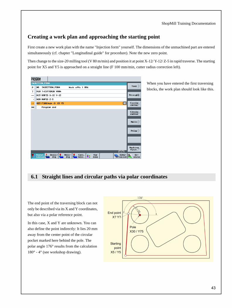
Creating a work plan and approaching the starting point
First create a new work plan with the name "Injection form" yourself. The dimensions of the unmachined part are entered simultaneously (cf. chapter "Longitudinal guide" for procedure). Note the new zero point.
Then change to the size-20 milling tool (V 80 m/min) and position it at point X-12/ Y-12/ Z-5 in rapid traverse. The starting point for X5 and Y5 is approached on a straight line (F 100 mm/min, cutter radius correction left).
When you have entered the first traversing blocks, the work plan should look like this.
The end point of the traversing block can not only be described via its X and Y coordinates, but also via a polar reference point.
In this case, X and Y are unknown. You can also define the point indirectly: It lies 20 mm away from the center point of the circular pocket marked here behind the pole. The polar angle 176° results from the calculation 180° - 4° (see workshop drawing).
6.1 Straight lines and circular paths via polar coordinates
Startingpoint
X5 / Y5
PoleX30 / Y75
End pointX? Y?
43
6 Example 2: Injection form
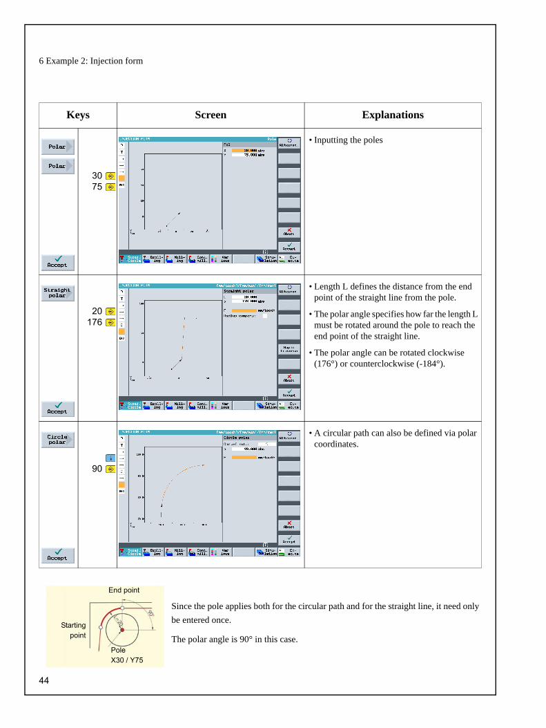
Since the pole applies both for the circular path and for the straight line, it need only be entered once.
The polar angle is 90° in this case.
Keys Screen Explanations
3075
• Inputting the poles
20176
• Length L defines the distance from the end point of the straight line from the pole.
• The polar angle specifies how far the length L must be rotated around the pole to reach the end point of the straight line.
• The polar angle can be rotated clockwise (176°) or counterclockwise (-184°).
90
• A circular path can also be defined via polar coordinates.
End point
Startingpoint
PoleX30 / Y75
44

ShopMill Training Documentation
120
• Since the end point of the straight line is uniquely identified, the straight line function can be used here.
12075
• Since the end point of the next circular path is unknown, you must work with polar coordi-nates here again.
• The pole of the circular path is known from the drawing.
4
• The polar angle is also known on account of the symmetry.
1455
• The end point of the straight line is known and may therefore be entered directly.
45

6 Example 2: Injection form
Further information about these variations for the workpiece representation are given at the end of Chapter 7.
-20
• With the last straight line, the contour has been milled fully once.
-12-122x3x
• The last traversing movement uses the speci-fied safety clearance; the radius correction is deactivated in this case.
The following simulation shows the production sequence to let you check it before the workpiece is produced. 6
ShopMill also allows you to
• cut,
• zoom,
• rotate the 3D view and
• view the workpiece in a three-side view.
46
ShopMill Training Documentation
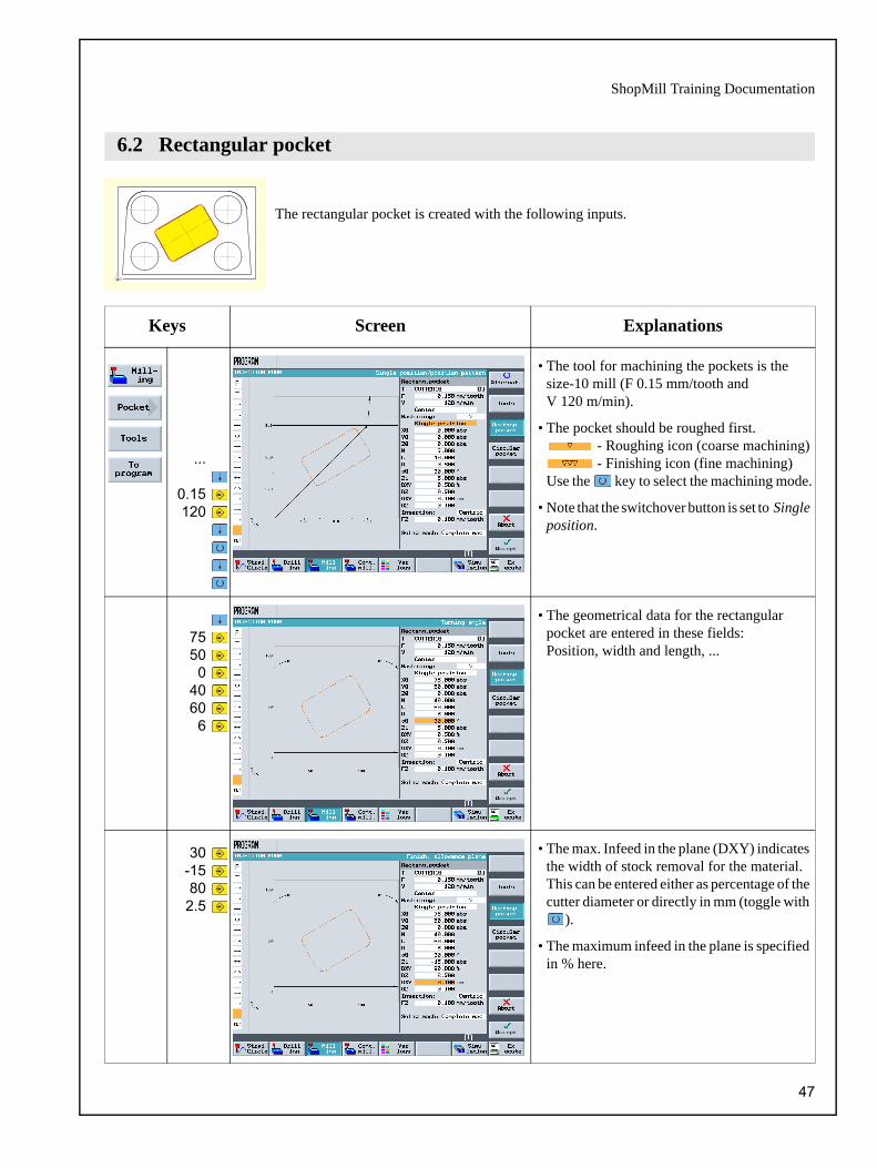
The rectangular pocket is created with the following inputs.
Keys Screen Explanations
...
0.15120
• The tool for machining the pockets is the size-10 mill (F 0.15 mm/tooth and V 120 m/min).
• The pocket should be roughed first. - Roughing icon (coarse machining) - Finishing icon (fine machining)
Use the key to select the machining mode.
• Note that the switchover button is set to Single position.
7550
04060
6
• The geometrical data for the rectangular pocket are entered in these fields: Position, width and length, ...
30-15802.5
• The max. Infeed in the plane (DXY) indicates the width of stock removal for the material. This can be entered either as percentage of the cutter diameter or directly in mm (toggle with
).
• The maximum infeed in the plane is specified in % here.
6.2 Rectangular pocket
47

6 Example 2: Injection form
0.30.3
22
• Select helical insertion, if not alreadyactivated.
• If the pocket is already prefabricated, the Solid mach: field can be set to Remachining. Then enter the size of the pre-fabricated pocket in the input fields displayed. Roughing of this area is then omitted.
0.08150
• The finishing work step is created next. Reduce the feedrate 0.08 mm/tooth, increase the cutting speed to 150 m/min and switch the machining mode from Roughing to Finishing ( ).
• With this setting, you finish edges and bottom. Alternatively, you may only finish edges ( ) or chamfer the pocket ( ).
DZ =Max. Infeed depth
UZ =Finishing allowance,
depth
UXY =Finishing allowance,
plane
Helical insertion Oscillating insertionCentered insertion
EP = Insertion pitchER = Insertion radius
EW = Insertion angle
48

ShopMill Training Documentation
The following entries create the circular pockets.
Keys Screen Explanations
0.15120
• The size-10 milling tool (F 0.15 mm/tooth and V120 m/min) is used to machine thepockets.
• Machining must be set to Roughing.
• Analogous to drilling, you can create pockets of a position pattern.
• In ShopMill, the last tool setting is stored. You must therefore switchover here if necessary.
30-1080
50.30.3
• The maximum infeed in the plane is specified in % here.
22
• The insertion must be set to helicalif required.
6.3 Circular pockets on a position pattern
49

6 Example 2: Injection form
0.08150
• The pockets should always be finished using the same milling tool (F 0.08 mm/tooth andV 150 m/min).
• The machining must be set to finishing.
2x3025
09050
22
• Now you must enter the data to position the circular pocket.
• The pattern type is set to Grid.
• Note: The description of the position pattern is made in the Drillng menu with the submenu Positioning (irrespective of the type of machining).
• Before is pressed, the simulation must be fully completed in the top view or in the 3-plane view.
• Before is pressed, the desired cut must be set using the cursor keys.
• The softkey can be used to display the new volume model during the course of the simulation and/or when the cutting path changes.
...
...
50

ShopMill Training Documentation
In this chapter, you learn about other important functions, in particular the contour calculator:
• Path milling for open contours
• Stock removal, residual material and finishing contour pockets
• Machining on several planes
• Considering obstacles
7 Example 3: Mold plate
51

7 Example 3: Mold plate
Creating a program
The workpiece dimensions must be taken from the drawing and entered in the program header of a new program. Observe the correct position of the zero point.
7
To enter complex contours, ShopMill provides a contour calculator, which you can use to simplify the entry of highly complex contours.
•Vertical route
•Horizontal route
•Diagonal route
•Arc
This graphic contour calculator lets you enter contours more easily and faster than with conventional programming - without the need of mathematics.
Keys Screen Explanations
M...
• Each contour will get its own name. This makes reading the program easier.
-35-100
• Enter the Starting point of the contour definition first.
• The starting point of the structure is simultaneously the starting point for machining the contour later.
• Note: You describe only the workpiece contour here, the approach and retraction paths are defined later.
7.1 Path milling for open contours
52

ShopMill Training Documentation
3515
• The first contour element is a vertical line with end point at Y20.The following circular contour can be entered simply as a transition element up to the next straight line in this dialog. The theoretical end point of the straight lines therefore lies at Y35.
• With the Alternative key, you can also design a chamfer as a transition element.
3515
• Continue on the horizontal plane. The Radius is entered as a filleting.
-100
• It is followed by a vertical path.
• The contour is thus fully defined and can be incorporated into the work plan.
...
0.15120
• To machine the contour you have created , you must now create the work step.
• The tool (CUTTER32) should move to the left of the contour. To do this, you must switch to
in the Radius comps. input field.
• ShopMill V6.4 and higher also allows backward milling (against the constructional direction).
• The first machining step performs roughing ( ) .
53

7 Example 3: Mold plate
010
50.30.3
• In the fields that follow, enter the start depth, the machining depth, the depth infeed and the final machining allowance.
• Note: The depth Z1 was switched to inc. This has the advantage that the actual depth of the pocket can always be entered without a sign. This simplifies the input of nested pockets.
3x
50.13x
5
• You can approach in a Quadrant, a Semi-circle, Vertical or on a Straight line.
• It makes sense here to approach the contour at a tangent on a straight line.
• The mill radius does not have to be considered for the approach length L1. This is computed automatically by ShopMill.
0.08150
• The following work step is to be finished along the pre-roughed contour. This is done by reducing the feedrate to0.08 mm/tooth, the cutting velocity toV 150 m/min increased and the machining to finishing ( ).
The two work steps are linked in the work plan.
The simulation and subsequent 3D view show the correct production of the workpiece. 7
54

ShopMill Training Documentation
This contour pocket is created below. Then, the pocket is machined and finished.
Keys Screen Explanations
M...
• The contour is assigned the name "MOLD_PLATE_Inside".
2x0
-90
• The starting point should lie at X0 and Y-90.
25
• Because the pocket is to be machined in syn-chronism, the contour must be designed in the same direction.
• As an exercise, the first arc should not be rounded but entered as a separate element. The straight line is therefore only designed up to X25.
530
-85
• When you enter the Y end point, you obtain two design solutions which can be called from the software via the softkey Dialog select. The solution selected turns black, the alternative green.
7.2 Stock removal, residual material and finishing of contour pockets
55

7 Example 3: Mold plate
• The Dialog accept softkey accepts the desired quadrant from the possible solutions.
• The geometry processor has automatically detected that the programmed arc connects tangential to the straight line. The correspond-ing softkey Tangent prev. elem is displayed in inverse mode (i.e. printed).
-205
• The end point of the of the straight lines is known. The transition to R36 is rounded with R5.
36-30-20
5
• A circular arc in clockwise direction follows.
56

ShopMill Training Documentation
-905
• The radius R5 is specified as a filleting.
• With the key Close contour, the contour is closed directly.
• The pocket contour is then fully defined and is incorporated in the work plan.
...
0.15120
• The pocket is to be machined using thesize-20 milling tool (F 0.15 mm/tooth and V 120 m/min).
• First of all, the pocket is roughed ( ).
01550
50.30.3
• The machining depth can also be entered as an incremental value. However, you must enter the depth as a positive value.
• The maximum infeed in the plane is specified in % here.
• The starting point (insertion position) is defined by ShopMill when Auto is selected.
57

7 Example 3: Mold plate
22
• The insertion should be helical with a pitch and a radius of 2mm.
...
0.1120
505
• Since the size-20 cutter cannot machine the R5 radius, the "corners" of the material are left over. The Residual material function and a smaller milling tool (CUTTER10 withF 0.1 mm/tooth and V120 m/min) are used to accurately rough off the areas that have not yet been machined.
• The maximum infeed in the plane should be 50%.
0.08150
• You can also use the Stock removal function to post-machine the pocket. The machining must be switched to Finish bottom ( ).
• The allowance entered previously for rough-ing must be set once again for the values in the fields Finishing allowance in the plane (UXY) and Finishing allowance in depth (UZ). This value is relevant for the automatic computation of the traversing paths.
3x
• The Finish Wall ( ) function machines the residual material at the contour.
58

ShopMill Training Documentation
7.3 Machining on several planes
The size-60 circular pocket is milled in two work steps in exactly the same way as in the "Injection form" example.
The first step is to rough the pocket down to -9.7 mm using the size-20 milling tool.
In the second step, the pocket is finished with the same tool.
59

7 Example 3: Mold plate
Then, the inside circular pocket is machined down to the depth of -20 mm.
You must note here that the starting depth is -10 mm not 0 mm.
Keys Screen Explanations
0.15120
• When you have entered the values as shown in the figure, you can accept the dialog box.
0.08150
• The second step is to finish the pocket.
• The position, size and dimensions are taken automatically from the roughing step per-formed previously. So you only have to enter the technology values.
• The value Z0 (= High workpiece) indicates the starting depth for machining.
• The more complex the workpiece, the greater the significance of the 3D image in the pre-liminary production steps.
...7
60

ShopMill Training Documentation
Just as for "Longitudinal guide", you can also chain various drilling patterns for this workpiece. But you must remember that one or more "obstacles" have to be traversed, depending on the order of machining operations. Traversing between the holes is carried out with the safety distance or on the retract plane, as appropriate to the settings you have defined.
First, create the work steps: Center and Drill in the manner you were taught in Chapter 5.
After you have created these two work steps, enter the associated drilling positions on the next page.
7.4 Considering obstacles
1. Work step Centering
2. Work step Drilling
61

7 Example 3: Mold plate
Keys Screen Explanations
-10-42.5-92.5
9045
4
• First, create the left-hand row of holesin the sequence from bottom to top.
1
• The Obstacle function is used to enter a travel path at a height of 1 mm, since the next step is to practice drilling the right-hand row of holes also from bottom to top.
2x42.5
• Enter the second drilling route here.
• To obtain the next drilling pattern, the circle of holes, you must also navigate around an obstacle.
62

ShopMill Training Documentation
Further information about the display of the workpiece:1. The simulation can only run in the Top view or in the 3-plane view. The last setting remains active.2. A static display can also be made in the volume model.
-103x
22.56
• The six holes form a full circle.
• To produce the last hole, you must again nav-igate around an obstacle.
-100
42.5
• Enter the last drilling position
• Delete any positions that already existwith .
• Note: This programming example should help you become acquainted with the Obstacle function. There are of course more elegant ways to program the drilling positions that have only one obstacle to overcome. Try out various strategies yourself
After simulation, you can use the
orkeys to switch to other display.
If the key is pressed Top view or 3-plane view, these softkeys appear to let you increase the view zoom factor.
If you press the Details key in the volume model,
softkeys appear to let you select the various view directions.
You can use the arrow keys to preset the cutting path execute this path with the key.
63

8 Example 4: Lever
In this chapter, you become acquainted with the further important functions of ShopMill:
• Face milling
• Creating borders (auxiliary pockets) for solid machining around islands
• Creating circular islands by copying
• Extended editor and producing the islands
• Deep-hole drilling, helical milling, boring and thread cutting
• Programming contours with polar coordinates (new with ShopMill V 6.4 and higher)
8 Example 4: Lever
64

ShopMill Training Documentation
Creating a work plan
The workpiece dimensions must be taken from the drawing and entered in the program header. Here, you must observe that the unmachined part is to be 25 mm thick and that corner point 1 must therefore be set to 5 mm in Z.
When you have entered the data, the input window should look like this.
Keys Screen Explanations
...
0.1120
• When the function is called, you can choose from various machining directions, which are selected via the vertical softkey bar.
• FACEMILL63 is used(F 0.1 mm/tooth and V 120 m/min).
• The surface is roughed first. To do this, you must switch the Machine field to .
• The dimensions of the unmachined part and the insertion depth and finishing allowance still have to be defined (see input window).
0.08150
• To finish the surface, you must adapt the technology values (F 0.08 mm/tooth and V 150 m/min) and switch over the machining mode from roughing to finishing ( ).
• The final allowance must have the same value as for roughing and finishing because the allowance for the subsequent finishing oper-ating, and during finishing, refers to the mate-rial thickness still to be machined.
8.1 Face milling
...8
65

8 Example 4: Lever
Islands are described as a contour in the graphic contour calculator in exactly the same manner as pockets. They do not become islands until they are linked in the work plan: The first contour always describes the pocket. One or more subse-quent contours are interpreted as islands. Since there is no pocket in the "lever" example, a theoretical auxiliary pocket is applied to the outside contour. This is used as the required outside boundary for the traversing paths and thus defines the framework in which the tool movements are carried out.
Keys Screen Explanations
R...
• The outside contour is given the name "LEVER_Rectangular_Area".
8.2 Creating a border for the lever island
Design the pocket with the distances shown on the left (variable values) around the unmachined part. The corners are rounded with R15.
Always make sure that the values you select cover the workpiece edges of the "Pocket"
8
When the contour is finished, the screen looks like this.
8
66
ShopMill Training Documentation
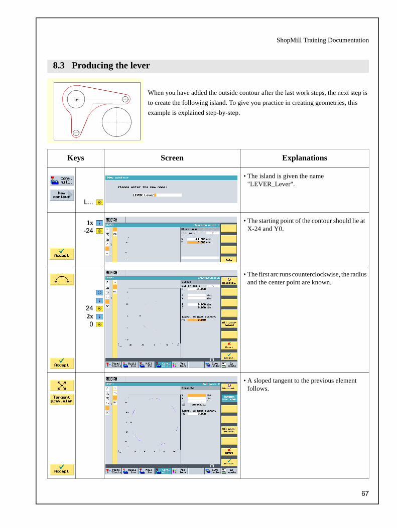
When you have added the outside contour after the last work steps, the next step is to create the following island. To give you practice in creating geometries, this example is explained step-by-step.
Keys Screen Explanations
L...
• The island is given the name "LEVER_Lever".
1x-24
• The starting point of the contour should lie at X-24 and Y0.
242x0
• The first arc runs counterclockwise, the radius and the center point are known.
• A sloped tangent to the previous elementfollows.
8.3 Producing the lever
67

8 Example 4: Lever
885-885
• A tangential circular path follows.
• Radius, center point and corner points are known.
30
40
• A horizontal route to end point X30 follows.
• The transition to the next element is to have a radius of 40 mm.
• A sloped path follows.
• Note: The tangential transition is always relative to the main element only, i.e. in this case the straight line does not lie at a tangent.
main element
rounding
main element
not tangential
68

ShopMill Training Documentation
82x
-58
0
-58
• A tangential arc follows with a center point and end point that are known.
• The All parameters function provides detailed information about the arc. This can be used to check the input values (for example: Does the arc end vertically ...?).
-27
18
• A vertical path (automatically at a tangent) follows to end point Y-27.
• The transition to the next straight line is to be rounded with R18.
• This is followed by an slope.
24-24
00
• The contour is closed with an arc to the starting point.
69

8 Example 4: Lever
The materials around the lever are first roughed and then finished to a depth of -6.
Keys Screen Explanations
...
0.15120
06
5060...
• The pocket is machined and the lever contour taken into account. The CUTTER20 tool is used for roughing (F 0.15 mm/tooth and V 120 m/min).
• The maximum infeed in the plane is specified in % here.
...
0.08150
06
500
70-40
...
• The base of the pocket is finished(F 0.08 mm/tooth and V 150 m/min).
70

ShopMill Training Documentation
A border is created below as a travers-ing limit for milling to depth -3.
The values R36 and R26 are derived from the relevant Island radius + cutter diameter (here 20 mm + 1 mm allowance).
The radii R5 and R15 can be selected freely.
Keys Screen Explanations
L...
• The contour is assigned the name "LEVER_Lever_Area"
• The limit for the traversing paths is (as described above) designed around the work-piece contour in such a manner that the size-20 cutter fits between the limitation and the islands.
• Enter this limiting contour in the same way as the lever contour.
8.4 Creating a border for the circular islands
71
8 Example 4: Lever
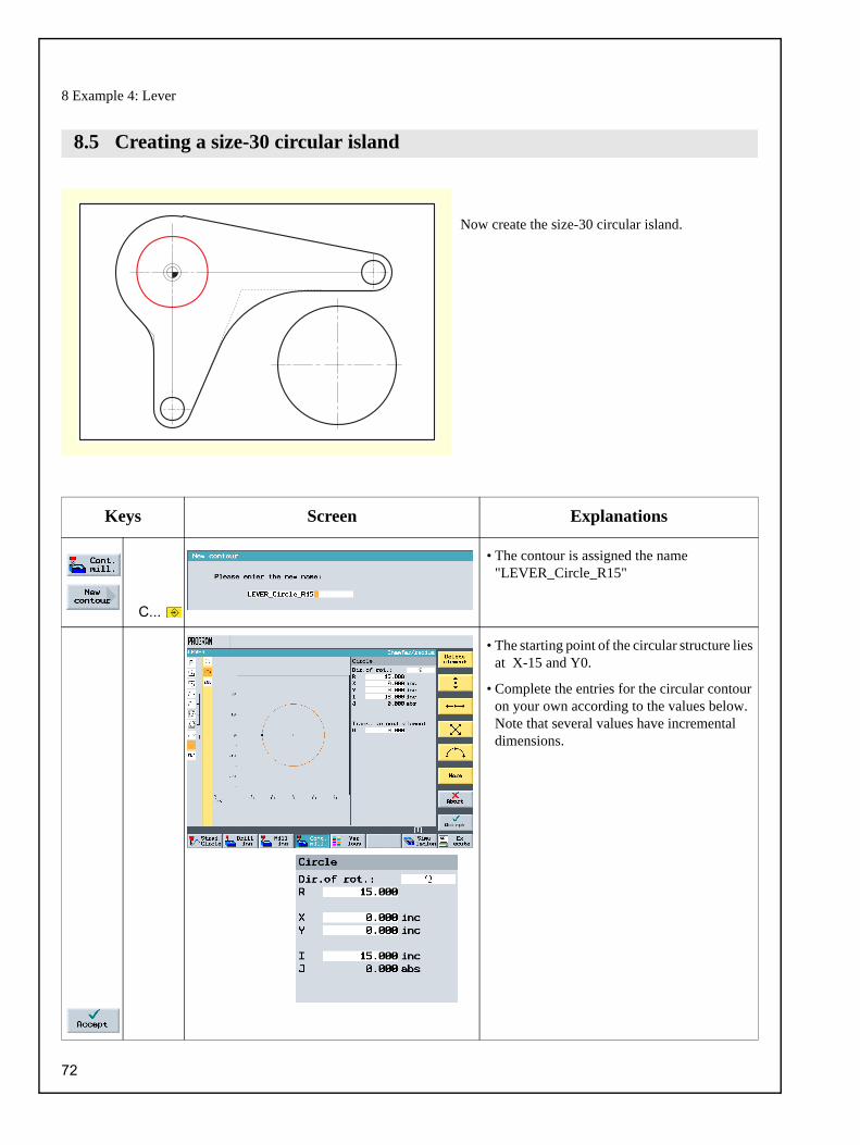
Now create the size-30 circular island.
Keys Screen Explanations
C...
• The contour is assigned the name "LEVER_Circle_R15"
• The starting point of the circular structure lies at X-15 and Y0.
• Complete the entries for the circular contour on your own according to the values below. Note that several values have incremental dimensions.
8.5 Creating a size-30 circular island
72

ShopMill Training Documentation
Now create the first size-10 circular island.
Keys Screen Explanations
C...
• The contour is assigned the name "LEVER_Circle_R5_A"
• The starting point of the circular island lies at X80 and Y0.
• Since these circular islands are copied below, the contour must be input as incremental so that only the starting point has to be changed after copying.
• When you have entered the circle, the work plan graphic looks like the one shown here, if you have activated the work plan graphic with
.
8.6 Creating a size-10 circular island
73

8 Example 4: Lever
In the section below, you learn how to copy in ShopMill.
Keys Screen Explanations
• Click on the key to open the extended editor and then copy the contour.
• Insert the copied contour.
• Because changes to the contours affect other contours that have the same name, the contour must be renamed.
B
• Only the name of the contour needs to be changed to "LEVER_CIRCLE_R5_B" in the information dialog. You have now created a copy of the first circular island.
2x-5
-58
• After selecting the "LEVER_CIRCLE_R5_B" contour, click on the key to call up the contour so that you can make changes.
• Because the contour was previously entered incrementally, only the start point needs to be changed.
• Click on the key to open all geometry elements to allow changes to be made.
8.7 Copying the size-10 circular island
74

ShopMill Training Documentation
ShopMill offers a series of special functions that allow multiple use and management of sections of the work plan. These special functions can be reached at any time via the key on the flat panel.
These functions are explained below:
Some of the functions described initially are used below to produce 3 circular islands effectively. The efficiency is obtained by copying the existing work steps.
The border highlighted red in section 8.4 is used as the traversing path limitation here.
You can use the Mark function to select several work steps for further processing (e.g. Copy or Cut).
The Copy function copies the work steps to the clipboard.
The Paste function adds work steps to the work plan from the clipboard. Pasting is always performed behind the marked work step.
The Cut function copies work steps to the clipboard and at the same time deletes them from their orig-inal location. The softkey is used purely for deletion purposes.
You can use the Find function to look for texts in the program.
The Rename function can be used to change the names of the contours, directories and workplans.
The Renumber function renumbers the work steps.
The Back function returns you to the previous menu.
8.8 Production of the circular island using the extended editor
75

8 Example 4: Lever
Keys Screen Explanations
• The work plan should now look like this.
5x
4x
• The two previous stock removal technologies are added to the chained contours with the Copy function.
• The two stock removal technologies must now be adapted to the new machining depth.
5x3
4x
70-20
• The roughing depth is set with the value Z1 to 3 mm and a starting point selected outside the residual material.
76

ShopMill Training Documentation
... is shown for checking.
5x3
5x-20
• The finishing depth is also adapted to suit.
• The geometries that belong to the finishing technology are displayed here (work plan graphic).
• As before: The simulation ...
77

8 Example 4: Lever
A drill is used below.
Keys Screen Explanations
...
0.1120
-21
• PREDRILL30 is used for predrilling(F 0.1 mm/rev and V 120 m/min).
• The depth reference point is set to tip with the setting abs.
-670
-40
• The drilling position is entered here.
8.9 Deep-hole drilling
78

ShopMill Training Documentation
Below, a milling tool is used to remove the residual material in a spiral motion, referred to as a helix.
Keys Screen Explanations
...
• The helix is used to remove the remaining circular ring after drilling. The CUTTER20 is used to do this (V 120 m/min).
82-40
-5
3x
• Since you are milling without cutter radius correction here, the milling tool must bepositioned on the core hole diameter (here 45.84 mm) minus the finishing allowance.
70-40
3-230.1
• The helix is milled in synchronism.
• The pitch of the helix is 3 mm.
• Since the tool travels over a sloped path, 6 revolutions are created here to prevent any residual material being left over (although the final depth is reached after five).
8.10 Helical milling
79
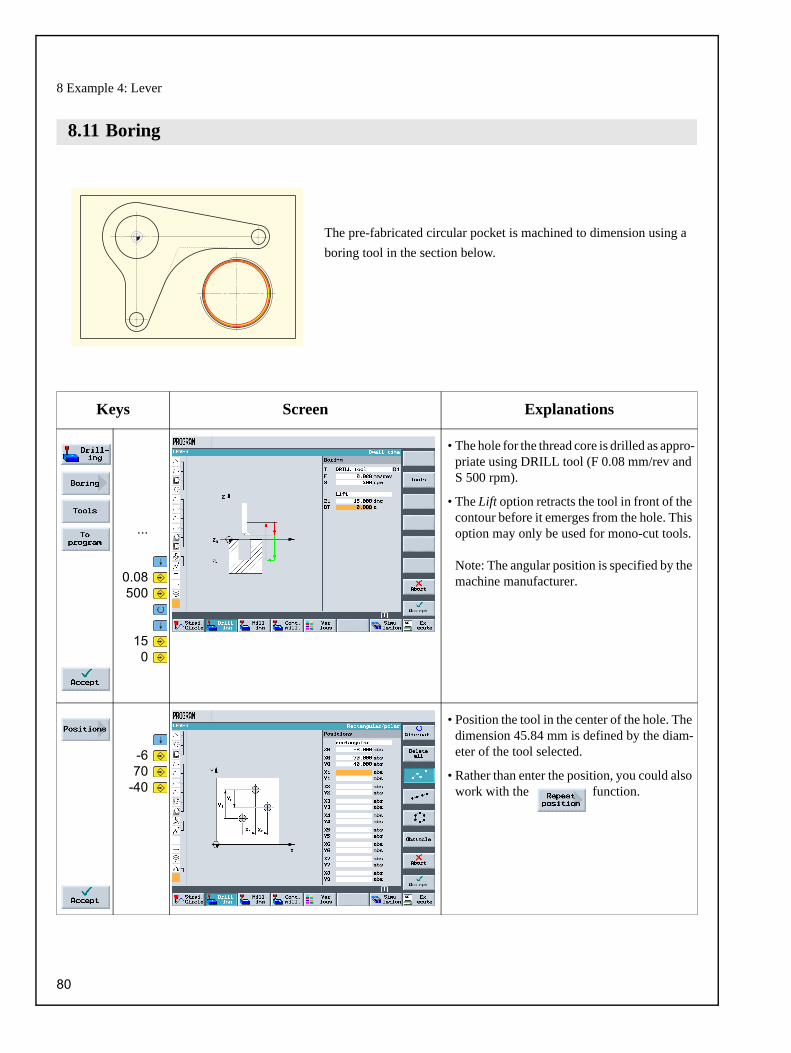
8 Example 4: Lever
The pre-fabricated circular pocket is machined to dimension using a boring tool in the section below.
Keys Screen Explanations
...
0.08500
150
• The hole for the thread core is drilled as appro-priate using DRILL tool (F 0.08 mm/rev and S 500 rpm).
• The Lift option retracts the tool in front of the contour before it emerges from the hole. This option may only be used for mono-cut tools.
Note: The angular position is specified by the machine manufacturer.
-670
-40
• Position the tool in the center of the hole. The dimension 45.84 mm is defined by the diam-eter of the tool selected.
• Rather than enter the position, you could also work with the function.
8.11 Boring
80

ShopMill Training Documentation
The thread is produced with a thread cutter below.
Keys Screen Explanations
0.08150
...
• The thread is milled from top to bottom. Use the THREADCUTTER to do this(F 0.08 mm/tooth, V 150 m/min and a pitch of 2 mm).
• A right-hand thread is to be milled to Z-23 absolute. The overlap of 3 mm means that the thread is definitely milled properly up to the workpiece, even if the bottom tooth is worn slightly.
• The help displays are very useful when entering values.
-670
-40
• The position of the thread is specified here.
8.12 Thread cutting
81

ShopMill Training Documentation
It is not uncommon that contour elements in workpiece drawings refer to a pole point. If so, you do not know the Cartesian coordinates (X/Y), but the polar coordinates, i.e. the distance (L) and the angle ( ) to this pole.
With ShopMill V 6.4 and higher, also such cases can easily be programmed graphically without pocket calculator or auxiliary construction.
You can understand this by means of a small change of the lever: The lower "lever arm"
is then no longer perpendicular to zero at X0 but rotated around 10° in clockwise direc-
tion.
Keys Screen Explanations
3x
....
• First move the cursor to this arc, for which new center-point dimensions are to be entered.
• First of all, the pole must be set in the zero point before the arc.
• Therefore, place the cursor on the element before the arc and then add the pole at this position.
8.13 Programming contours with polar coordinates
82

ShopMill Training Documentation
3x
4x
2x
• In the dialog window of the arc, delete the values Y-58, I0 and J-58 which are no longer valid.
3x
58
-100
• To enter the center-point, switch the coordi-nates from Cartesian to polar, and enter the distance to the pole (L2) and the polar angle ( 2).
• Where required, the auxiliary graphics ( ) illustrates the meaning of the input values.
• The work plan graphics show that the auxilia-ry pocket LEVER_LEVER_AREA in line N40 and the circular island LEVER_CIRCLE_R5_B in line N55 will have to be adjusted in a similar manner .
... • Change these two contours yourself.
• With the auxiliary pocket, you can, of course, have a rather "rough" approach, i.e. approximate the center-point of arc R26 (with polar dimensions) with Cartesian coordinates (X-10/Y-57). The contour can then be terminated directly with a vertical line.
• In the case of the circular island, the starting point is already defined by polar coordinates. You then still have to change the center-point of the full circular arc.
83

9 Example 5: Flange
87This chapter addresses the following new contents:
• Creating a subroutine
• Mirroring work steps
• Rotation of pockets
• Chamfering any contours
• Longitudinal and circumferential grooves
Remarks: Up to now, almost all keys that you pressed were displayed. In this example, the entries are no longer specified, only the main keys. Since the values in the dialogs are very important, however, these dialogs are shown in large format. The result is shown as an overall display in the right-hand column.
9 Example 5: Flange
84

ShopMill Training Documentation
The example demonstrates the creation and mode of operation of the subroutines for the "flange" workpiece. The four corners are machined using a subroutine and the mirroring function below.
Keys Screen Explanations
C...
• The subroutine, which does not differ formally from the main program, is given the name "Corner_machining".
• Enter these data for the program header. Zero and blank dimensions are determined later centrally in the main program.
C...
• The contour is assigned the name "CORNER_MACHINI_Surface".
5750
• For example, the above right corner should be constructed.
• Enter a suitable starting point.
9.1 Creating a subroutine
...
85

9 Example 5: Flange
When you have entered the two contour elements, the screen should look like this.
Incorporate the contour in the work plan.
The approach and return paths are approached here on a straight line. The length values are the distances between the edge of the milling tool and the workpiece.
Keys Screen Explanations
• The contour is to be roughed with a size-20 cutter (F 0.15 mm/tooth and V 120 m/min).
... ...9
86

ShopMill Training Documentation
Keys Screen Explanations
• The contour is to be finished with the same cutter (F 0.08 mm/tooth and V 150 m/min).
C...
• Next, the corner of the unmachined cuboid should be rounded with R5. The contour is assigned the name "CORNER_MACHINI_Arc".
7050
• Enter the starting point
87

9 Example 5: Flange
Enter the contour and associated work steps.
Complete subroutine consisting of the geometric and technology data
Enter the geometry
Technology for roughingthe contour
Technology for finishingthe contour
88

ShopMill Training Documentation
When the subprogram is completed, the main program is then created. The mirroring function from the Transformation menu can be used for all four workpiece corners.
Mirroring can be performed in two different ways: new and additivenew means: mirroring is carried out from the location where the 1st machining step has been carried out. additive means: mirroring is carried out from the location machined last.
The order of machining is outlined in the schematic below with the setting new:
9.2 Mirroring work steps
1. Machining (see subprogram) 2. Machining: Mirroring of the X axis (the X values are mirrored here)
3. Machining: mirroring of the X and Y axes(the X and Y values are mirrored here)
4. Machining: mirroring of the Y axis (the Y values are mirrored here)
89

9 Example 5: Flange
Keys Screen Explanations
F...
• The main program gets the name"Flange".
• The program header is entered.
C...
• The Various key allows you to call thesubroutine.
• If the subroutine was created in the same directory as the main program, the input field "Path/workpiece" may remain empty.
• Enter the name of the subroutine in the input field. ("Corner_machining").
• The Transformations function can be used to shift, rotate and perform similar operations on the axes.
• Preparation of the 2nd machining: Mirroring the X values
90

ShopMill Training Documentation
Then the subprogram behind the mirroring function is copied: The 2nd machining step.
These processes mirroring and subprogram call are then repeated for the two other corners.
After the 4th machining step, the mirroring function is deactivated in all three axes (see line N45).
Auxilary display for mirroring
91
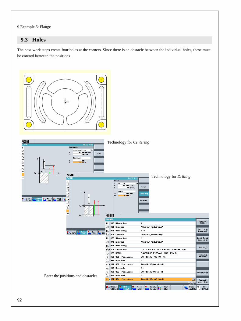
9 Example 5: Flange
The next work steps create four holes at the corners. Since there is an obstacle between the individual holes, these must be entered between the positions.
9.3 Holes
Technology for Centering 9
Technology for Drilling 9
Enter the positions and obstacles.9
92

ShopMill Training Documentation
The contour and machining for the pocket highlighted in yellow are programmed below.
The two other pockets are created by rotating the coordinate system.
Keys Screen Explanations
N...
• The contour is assigned the name "FLANGE_Nodule".
042
• Enter the starting point.
• The arc R42 is described uniquely, for exam-ple via the radius, the center point in X and the run out angle.
• The design is carried out counterclockwise so that the pocket can also be finished in synchro-nism.
9.4 Rotation of pockets
93

9 Example 5: Flange
Keys Screen Explanations
• Creating the diagonal route
• Creating the 2nd arc
94

ShopMill Training Documentation
• Creating the 2nd diagonal route
• Creating the final arc
• Take the contour pocket from the work plan.
95

9 Example 5: Flange
Create the following work steps on your own:
3x
3x
• Now mark and copy the complete work step to define the pocket machining to the clip-board.
Rough the pocket 9
Finish the pocket base 9
Finish the pocket edge 9
96

ShopMill Training Documentation
3x120
• Rotate the coordinate system 120° around the Z axis.
• Paste the copied work steps.
• Enter a further rotation of 120°.
• Paste the work steps stored on the clipboard.
97

9 Example 5: Flange
ShopMill version V6.4 and higher supports chamfering of contours. The selection field Machining - which is used for selecting roughing ( ), finishing ( ) etc. - has therefore been supplemented with the "Chamfering" option ( ).
The following figures demonstrate this on the example of the last milled "nodule".
• Press new and the value 0° to cancel therotation.
9.5 Chamfering contours
Work step “Chamfering” chained with the contour 9
A tool type is used which allows the input of a nose angle (here a center drill). 9
9
Machining of the chamfer is programmed via the chamfer width (FS) and the insertion depth of the tool tip (ZFS). 9
Chamfered contour in the 3-plane simulation 9
98

ShopMill Training Documentation
The grooves are programmed at the end. They must then be brought to the correct position via position pattern and positioning on a full circle.
Keys Screen Explanations
• The longitudinal grooves are roughed with the CUTTER6 tool (F 0.08 mm/tooth andV 120 m/min).
• The longitudinal grooves are finished with the same tool (F 0.05 mm/tooth andV 150 m/min).
9.6 Longitudinal groove and circumferential groove
99

9 Example 5: Flange
066
0-66
0
• Enter the two longitudinal groove positions
• The reference point lies in the center of the groove.
• The circumferential grooves are roughed using the CUTTER6 tool (F 0.08 mm/tooth and FZ 0.08 mm/gear tooth and V 120 m/min).
• The Full circle option positions the circle automatically at a constant distance.
• The reference point in X/Y/Z refers to the center point of the circle of circumferential grooves.
• The circumferential grooves are finished with the same tool (F 0.05 mm/tooth,FZ 0.05 mm/tooth and V 150 m/min).
100

ShopMill Training Documentation
And finally: work plan, online graphique and 3D view
Excerpt from the work plan 9
3D view 9
The online graphique 9
101

10 And now we can start production
When you have acquired a sound knowledge of how to create a work plan with ShopMill by working through the examples, you can move on to produce workpieces.
When you activate the control, you must approach the reference point before you run work plans or before you traverse manually. This enables ShopMill to find the counter starting point for the linear measurement system in the machine.
Since approaching the reference point may vary depending on the machine type and manufacturer, we can only provide a rough guide here:
10 So now we can start
10.1 Approach reference point
1. Move the tool to a free location in the work space, from which you can move in all directions without collision. When you do this make sure that the tool does not then lie behind the reference point of the relevant axis (since the reference point of each axis is only approached in one direction, it is otherwise not possible to reach this point).
2. Approach the reference point exactly according to the specifi-cations of the machine manufacturer. 10
102

ShopMill Training Documentation
In order to ensure production true-to-dimension, and also for your safety, make sure that the workpiece is clamped firmly.
Since ShopMill cannot guess where the workpiece is in the work area, you must determine the workpiece zero.
In the plane, the workpiece is usually set
• using the 3D key or
• with the edge key.
In the tool axis, the workpiece zero is usually set
• by clicking the 3D key
• by scratching with a tool.
10.2 Clamp the workpiece
Normally, bolted machine blocks ...
... or metal clamps are used for this
10.3 Set the workpiece zero
Symbol for workpiece zero W 10
Please observe the instructions of the manufacturer when using measuring instruments or measuring cycles. 10
103

10 And now we can start production
The machine is now ready, the workpiece set up and the tools calibrated (see Chapter 4). Now you can get started:
Keys Screen Explanations
• Select the directory that contains the work plan you wish to use. The directory for the examples from this manual is WORKPIECES.
• The Execute key loads the work plan in AUTO mode and switches to it.
• If you want to see a simulation during produc-tion, you must select the Real-sim. function before you start. Only then all traversing movements and their effects are displayed.
• Since the work plan has not yet been run and checked, set the feedrate override to zero so that you are "in control" from the start.
• Start production with the key and check the speed of the tool movements using the feedrate override.
10.4 Edit work plan
104
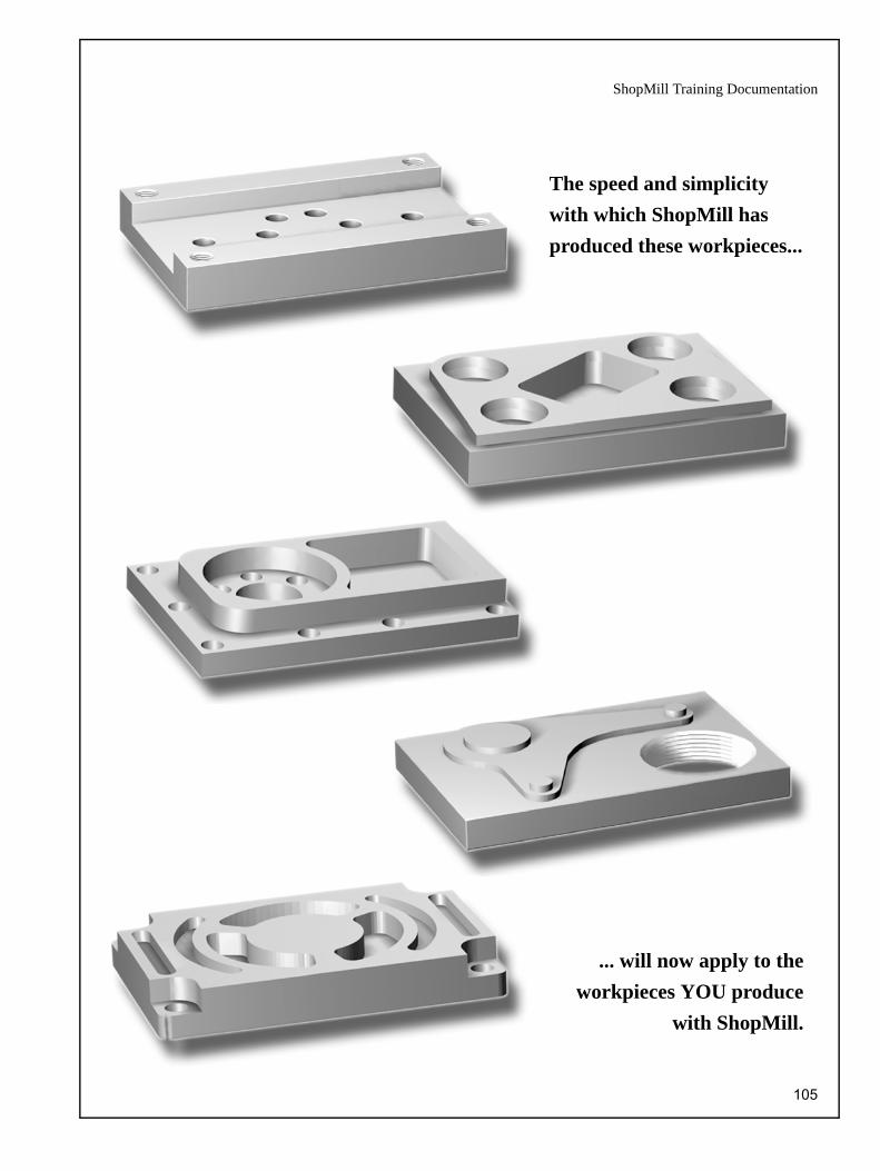
ShopMill Training Documentation
The speed and simplicity with which ShopMill has produced these workpieces...
... will now apply to theworkpieces YOU produce
with ShopMill.
105

11 How fit are you with ShopMill?
The following 4 exercises form the base for your personal test in your work with ShopMill. A possible work plan is dis-played to assist you in each case. The times stated are based on the procedure defined in the work plan. Please regard the times stated as a rough estimate for your answer to the question above.
Exercise 1: Can you manage that with ShopMill in 10 Minutes?
The rotated rectangular pocket has been constructed in the original coordinate system here. The start point initially lies on the zero point. An auxiliary straight line at 15° up to the edge of the pocket. The coordinates of this end point are the start-ing point for the actual construction. The auxiliary straight line must be deleted.ShopMill also provides other ways to achieve this goal, e.g. with Rotation function or with the cycle rectangular spigot (see Exercise 3). Test which way is quickest for you and this procedure brings you the shortest production time.
11 How fit are you with ShopMill?
106

ShopMill Training Documentation
Exercise 2: Can you manage that with ShopMill in 15 minutes?
Even if it looks complicated, this contour presents no problem to ShopMill. And the automatic stock removal for residual material can be applied with optimum results here. Compare the production times if you were to remove all that with CUTTER10.
All non-dimensioned radii R6
107
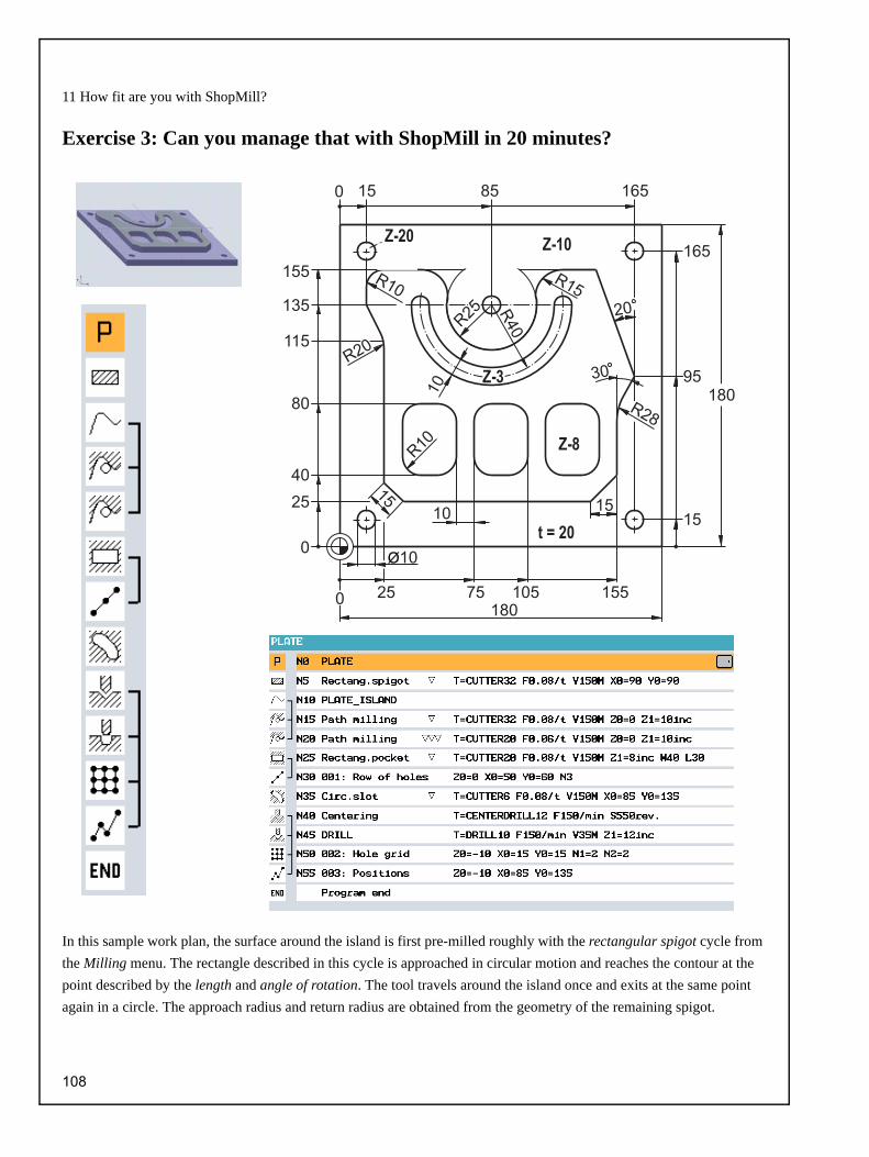
11 How fit are you with ShopMill?
Exercise 3: Can you manage that with ShopMill in 20 minutes?
In this sample work plan, the surface around the island is first pre-milled roughly with the rectangular spigot cycle from the Milling menu. The rectangle described in this cycle is approached in circular motion and reaches the contour at the point described by the length and angle of rotation. The tool travels around the island once and exits at the same point again in a circle. The approach radius and return radius are obtained from the geometry of the remaining spigot.
108

ShopMill Training Documentation
Exercise 4: Can you manage that with ShopMill in 20 minutes?
In this sample work plan, the circular outside contour has been milled using circular outside contour and the Circular spigot cycle. The functional operation corresponds essentially to the rectangular spigots (see sample work plan forExercise 3). The common center-point of the two arcs R45 and R50 (= starting point for the actual construction) is deter-mined via polar coordinates (25 mm under 65°, relative to the pole point at X0/Y0, cf. Section 8.13).
From software version V6.4, a flexibly usable Engraving cycle is available under the Milling menu.
109

ShopMill Training Documentation
Index
AAbs............................................................... 40Absolute....................................................... 23Absolute dimensions.................................... 21Address........................................................ 23Alarms.......................................................... 17All parameters.............................................. 69Alternative key ........................................ 11, 37Angle............................................................ 22Approach and return ............................... 54, 86Approach starting point................................ 43Auxiliary pocket....................................... 66, 71Auxiliary straight line.................................. 106BBack............................................................. 75Basic menu .................................................. 12Basic operation ............................................ 10Benefits of ShopMill ....................................... 5Book of tables ......................................... 26, 27Border ..................................................... 66, 71Boring .......................................................... 80CCalibrating tools ........................................... 13Call tool........................................................ 37Calling dialogs ............................................. 36Carbide metals............................................. 24Cartesian ..................................................... 22CBN plates................................................... 24Centered insertion ....................................... 48Centering ..................................................... 61Ceramic plates............................................. 24Chaining....................................................... 15Chamfer ....................................................... 53Chamfering contours ................................... 98Circular movements..................................... 23Circular pocket............................................. 49Circumferential groove................................. 99Clamp the workpiece ................................. 103Clicking direction.......................................... 32Close contour............................................... 57CNC ISO...................................................... 16Comapre key ............................................... 33Contour ........................................................ 15Contour calculator..................................... 7, 52Contour pockets........................................... 55
110
Contour violation .......................................... 40Coolant......................................................... 28Copy............................................................. 75Copying contours ......................................... 74Copying of work plans.................................. 14Corner points................................................ 36Create program ............................................ 35Create subroutine......................................... 85Create work plan .......................................... 43Cut.............................................................9, 75Cutter radius compensation ......................... 37Cutting path.............................................50, 63Cutting velocity..........................................6, 26Cycles .......................................................... 16DDeep-hole drilling ......................................... 78Depth of cut.................................................. 41Depth reference ........................................... 41Dialog Accept ............................................... 56Dialog selection............................................ 55Diamond tools .............................................. 24Dimensioning ............................................... 36Direction of rotation ...................................... 28Directory..................................................14, 35Drill ............................................................... 25Drilling .......................................................... 61Drilling holes................................................. 39Duplo number............................................... 28EEdit work plan............................................. 104Entry for traversing path............................... 37Error message.............................................. 17Exercises.................................................... 106Extended editor ............................................ 75FFace mill ....................................................... 25Face milling .................................................. 65Feedrate per tooth.....................................6, 27Feedrates ..................................................... 27Find .............................................................. 75Fine machining............................................. 47Finishing....................................................... 88Finishing allowance...................................... 58Finishing allowance, depth........................... 48Finishing allowance, plane ........................... 48

ShopMill Training Documentation
Finishing symbol .......................................... 47Finishing the base........................................ 58Flat panel ..................................................... 11Full circle .................................................... 100Full CNC keyboard....................................... 11GGeometry basics .......................................... 18Gewindefräsen............................................. 82Graphic work plan .......................................... 6Grid .........................................................40, 50Grooves........................................................ 99HHelix ............................................................. 79Help displays.............................................5, 19HSS tool table .............................................. 24IIn opposite direction ..................................... 36INC............................................................... 40Incremental .................................................. 23Incremental dimension ................................. 21Infeed in the plane........................................ 47Info key......................................................... 11Input key....................................................... 11Inputting files ................................................ 14Insertion strategies....................................... 48LLine .............................................................. 40List of work steps ......................................... 38Location lock ................................................ 29Long hole milling tool ................................... 25Longitudinal groove...................................... 99MMachine control panel .................................. 11Machine operator panel ............................... 11Machine zero................................................ 20Machining depth........................................... 54Magazine.................................................17, 31Magazine list ................................................ 29Main element................................................ 68Managing work plans ................................... 14Manual mode ............................................... 13Mark ............................................................. 75Max. Infeed depth ........................................ 48Measure workpiece ...................................... 32
Messages .....................................................17Milling tools...................................................24Mirroring .......................................................89Miscellaneous...............................................90Movements on a straight line........................22Moving work plans........................................14NNC programs ................................................16NC spot drill ..................................................25Number of teeth............................................28OObstacles................................................ 61, 63Open contours ..............................................52Optimized return ....................................... 8, 36Oscillating insertion ......................................48Outputting data .............................................14PPaste ........................................................ 9, 75Path milling ............................................. 15, 52Pitch..............................................................41Pocket calculator function.............................11Points in the work area .................................20Polar .............................................................22Polar angle ............................................. 43, 44Polar coordinates.................................... 43, 82Pole ........................................................ 43, 44Position pattern......................................... 6, 49Position repetitions .......................................39Positioning ....................................................40Positions .......................................................39Potentiometer .............................................104Production ..................................................102Production time...............................................8Program header............................................35Program management............................ 34, 35Program Manager.........................................14Programming time ..........................................6RRadius ..........................................................53Radius offset.................................................53Rectangular pocket.......................................47Rectangular spigot......................................108Reference point ............................................20Remaining surface........................................48
111

ShopMill Training Documentation
Rename ....................................................... 75Renaming work plans .................................. 14Renumber .................................................... 75Residual material ...............................8, 58, 107Resistance to wear ...................................... 24Return plane ............................................. 8, 36Rotation ....................................................... 93Roughing ..................................................... 88Roughing symbol ......................................... 47Rounding ..................................................... 53Route of cut ................................................. 50SSafety clearance .......................................... 36Set the workpiece zero ....................13, 32, 103Set up machine............................................ 13Shaft milling tool insert................................. 25Shell end mill ............................................... 25Simulation ............................................... 38, 46Simulation - details ...................................... 63Sinumerik 810D ........................................... 16Sister tool..................................................... 28Softkeys ....................................................... 12Speed monitoring......................................... 28Speeds......................................................... 26Spiral drill ..................................................... 25Start depth ................................................... 54Start key..................................................... 104Stock removal ....................................48, 58, 80Straight line.................................................. 45Subroutine .............................................. 85, 88Switchover ................................................... 36Synchronism ................................................ 36TTangent at previous element ....................... 56Technology fundamentals............................ 24Thread ......................................................... 41Thread cuttering........................................... 81Times for work plans.................................. 106To the left of the contour.............................. 37To the right of the contour............................ 37Tool axes ..................................................... 18Tool break monitoring .................................. 28Tool condition .............................................. 29Tool list ................................................... 17, 28Tool management........................................ 28
112
Tool name .................................................... 28Tool types................................................28, 30Tool wear list ................................................ 29Tools for the examples................................. 30Top view....................................................... 63Toughness ................................................... 24Trace .......................................................... 104Training time .................................................. 5Transformations ........................................... 90Transisiton element...................................... 53Type of machining........................................ 36VVolume model .............................................. 63WWidth of mesh .............................................. 47Work plan graphic ...................................73, 77Work planes ................................................. 18Workpiece zero ............................................ 20ZZero offset .................................................... 32Zero points ................................................... 17

ShopMill Training Documentation
113
We are grateful to
AMF
DMG
Verlag Europa-Lehrmittel
Haimer
Iscar
Krupp-Widia
Neumo
Reckermann
Renishaw
Röhm
Sandvik
Seco
for the provision of graphic material on pages 17, 18, 24, 26, 27, 29, 33, 81, 102 and 103.
Index of figures

www.siemens.com/sinutrain
Subject to change without prior notice6FC5095-0AA50-0BP2
© Siemens AG 2008
Siemens AGIndustry SectorDrive TechnologiesMotion ControlPostfach 318091050 ErlangenDEUTSCHLAND
Further information
More details on JobShop are available under:www.siemens.com/jobshop
For detailed technical documentation refer to ourService&Support portal:www.siemens.com/automation/support
For contact persons near you refer to:www.siemens.com/automation/partner
Direct online ordering is possible in our mall:www.siemens.com/automation/mall