shopmill programming with g code - siemens ag · shopmill sinumerik 840d sl shopmill edition...
TRANSCRIPT
SINUMERIK 840D sl
ShopMill
Edition 01/2008
Operation/Programming
Introduction 1
Operation 2
Programming with
ShopMill 3
Programming with
G Code 4
Simulation 5
File Management 6
Mold making 7
Interrupts and
messages 8
Examples 9
Appendix A
Index B
Valid for Control SINUMERIK 840D sl/840DE sl Software Version NCU System Software for SINUMERIK 840D sl/840DE sl 1.5 with ShopMill 7.5
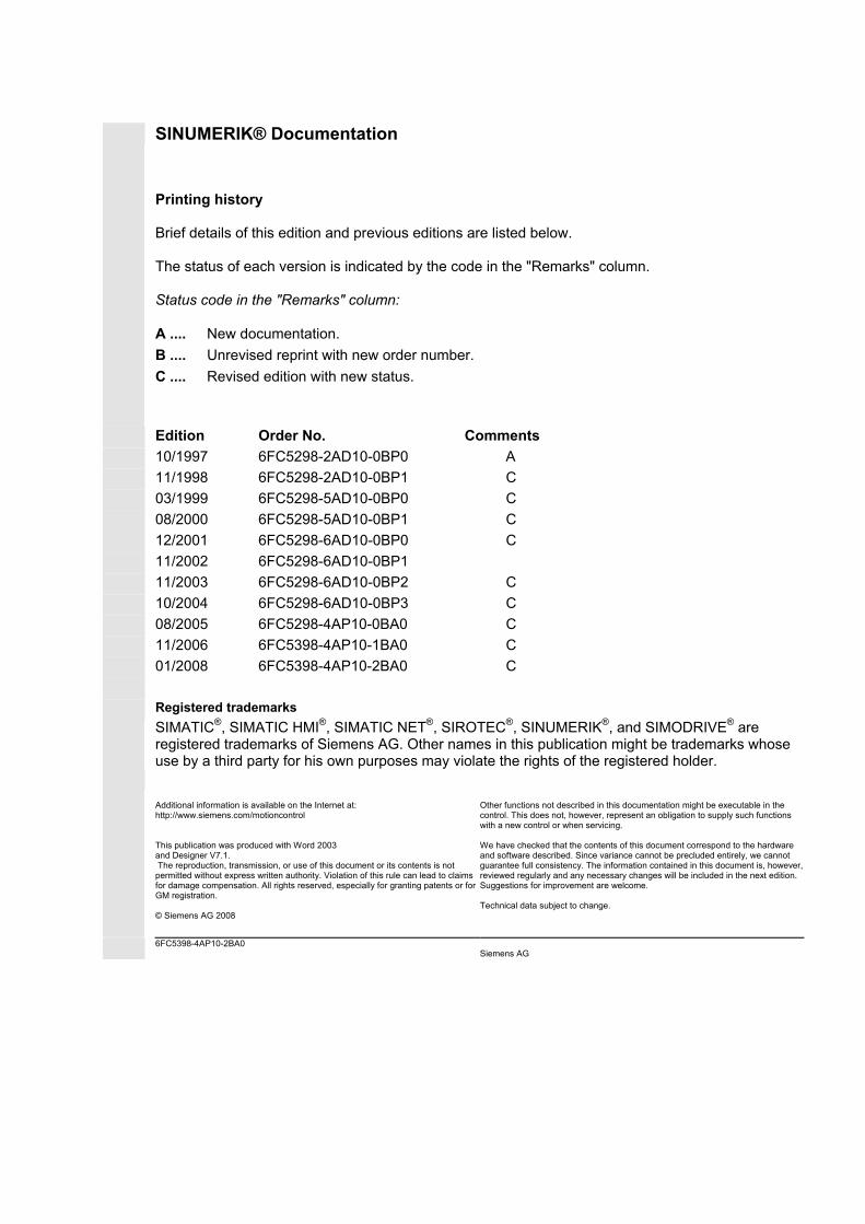
SINUMERIK® Documentation Printing history Brief details of this edition and previous editions are listed below. The status of each version is indicated by the code in the "Remarks" column. Status code in the "Remarks" column: A .... New documentation. B .... Unrevised reprint with new order number. C .... Revised edition with new status.
Edition Order No. Comments 10/1997 6FC5298-2AD10-0BP0 A 11/1998 6FC5298-2AD10-0BP1 C 03/1999 6FC5298-5AD10-0BP0 C 08/2000 6FC5298-5AD10-0BP1 C 12/2001 6FC5298-6AD10-0BP0 C 11/2002 6FC5298-6AD10-0BP1 11/2003 6FC5298-6AD10-0BP2 C 10/2004 6FC5298-6AD10-0BP3 C 08/2005 6FC5298-4AP10-0BA0 C 11/2006 6FC5398-4AP10-1BA0 C 01/2008 6FC5398-4AP10-2BA0 C Registered trademarks
SIMATIC®, SIMATIC HMI®, SIMATIC NET®, SIROTEC®, SINUMERIK®, and SIMODRIVE® are registered trademarks of Siemens AG. Other names in this publication might be trademarks whose use by a third party for his own purposes may violate the rights of the registered holder.
Additional information is available on the Internet at: http://www.siemens.com/motioncontrol This publication was produced with Word 2003 and Designer V7.1. The reproduction, transmission, or use of this document or its contents is not permitted without express written authority. Violation of this rule can lead to claims for damage compensation. All rights reserved, especially for granting patents or for GM registration. © Siemens AG 2008
Other functions not described in this documentation might be executable in the control. This does not, however, represent an obligation to supply such functions with a new control or when servicing. We have checked that the contents of this document correspond to the hardware and software described. Since variance cannot be precluded entirely, we cannot guarantee full consistency. The information contained in this document is, however, reviewed regularly and any necessary changes will be included in the next edition. Suggestions for improvement are welcome. Technical data subject to change.
6FC5398-4AP10-2BA0 Siemens AG
0 01/2008 Preface
0
© Siemens AG 2008 All rights reserved. SINUMERIK 840D sl Operation/Programming ShopMill (BASsl) - 01/2008 iii
Preface SINUMERIK
documentation The SINUMERIK documentation is organized in three parts: • General documentation • User documentation • Manufacturer/Service Documentation
An overview of publications, which is updated monthly and also provides information about the language versions available, can be found on the Internet at: http://www.siemens.com/motioncontrol Select the menu items "Support" "Technical Documentation" "Publications Overview.”
The Internet version of DOConCD (DOConWEB) is available at: http://www.automation.siemens.com/doconweb
Information on training offered and FAQs (frequently asked questions) is available on the Internet at: http://www.siemens.com/motioncontrol, under the menu item "Support".
Target group This documentation is intended for use by operators of vertical machining centers or universal milling machines controlled by the SINUMERIK 840D sI system.
Benefits This document familiarizes you with the operating elements and commands. Based on the manual, you are capable of responding to problems and to take corrective action.
Standard scope This documentation describes the functionality of the ShopMill operator interface. Extensions or changes made by the machine manufacturer are documented by the machine manufacturer.
Other functions not described in this documentation might be executable in the control. This does not, however, represent an obligation to supply such functions with a new control or when servicing.
Further, for the sake of simplicity, this documentation does not contain all detailed information about all types of the product and cannot cover every conceivable case of installation, operation or maintenance.
0 Preface 01/2008
0
© Siemens AG 2008 All rights reserved. iv SINUMERIK 840D sl Operation/Programming ShopMill (BASsl) - 01/2008
Technical Support If you have any technical questions, please contact our hotline: Europe/Africa Phone: +49 (0) 180 5050-222 Fax: +49 (0) 180 5050-223 Internet: http://www.siemens.com/automation/support-request
America Phone: +1 (0) 423 262 2522 Fax: +1 (0) 423 262 2200 E-mail: mailto:[email protected]
Asia/Pacific Phone: +86 (0) 1064 719 990 Fax: +86 (0) 1064 747 474 E-mail: mailto:[email protected]
Technology hotline Phone: +49 (0) 2166 5506-115 The hotline is available on weekdays from 8:00-17:00
Country-specific telephone numbers for technical support are provided at the following Internet address: http://www.siemens.com/automation/service&support
Questions about the manual
If you have any queries (suggestions, corrections) in relation to this documentation, please fax or e-mail us: Fax: +49 (0) 9131 98-63315
E-mail: mailto:[email protected] For the fax form, see the response sheet at the end of the document.
Internet address http://www.siemens.com/sinumerik
EC Conformity Declaration
The EC Declaration of Conformity for the EMC Directive can be found/obtained • On the Internet at
http://www.ad.siemens.de/csinfo under the product/order number 15257461
• At the relevant branch of the A&D MC business area of Siemens AG
0 01/2008 Preface
0
© Siemens AG 2008 All rights reserved. SINUMERIK 840D sl Operation/Programming ShopMill (BASsl) - 01/2008 v
Safety information This Manual contains information which you should carefully observe to ensure your own personal safety and the prevention of material damage. The notices referring to your personal safety are highlighted in the manual by a safety alert symbol, notices referring to property damage only, have no safety alert symbol. Depending on the hazard level, warnings are indicated in a descending order as follows:
Danger Indicates that death or severe personal injury will result if proper precautions are not taken.
Warning indicates that death or severe personal injury may result if proper precautions are not taken.
Caution means that there can be slight physical injury if the corresponding safety measures are not followed.
Caution without a safety alert symbol, indicates that property damage can result if proper precautions are not taken.
Notice Indicates that an undesirable result or condition can occur if the corresponding information is not observed.
If multiple levels of hazards can occur, the warning is always displayed with the highest possible level. If a warning notice is used with the safety alert symbol to warn against injury, this same notice may also include a warning regarding property damage.
Qualified personnel The associated device/system may only be set-up and operated in conjunction with this documentation. Commissioning and operation of a device/system may only be performed by qualified personnel. For the purpose of the safety information in this documentation, a “qualified person” is someone who is authorized to energize, ground, and tag equipment, systems, and circuits in accordance with established safety procedures.
0 Preface 01/2008
0
© Siemens AG 2008 All rights reserved. vi SINUMERIK 840D sl Operation/Programming ShopMill (BASsl) - 01/2008
Prescribed usage Please observe the following: Warning
The equipment may only be used for single-purpose applications explicitly described in the catalog and in the technical description, and only in conjunction with third-party devices and components approved by Siemens. Correct, reliable operation of the product required proper transport, storage, positioning and assembly, as well as careful operation and maintenance.
Structure of the documentation
The following information blocks, marked by pictograms, are used in this documentation:
Function
Background information
Sequence of operations
Explanation of the parameters
Additional notes
Software option The function described is a software option, i.e. the function can be executed on the control only if you have purchased and enabled the appropriate option.
Machine manufacturer The following reference appears wherever particular features or functions might have been changed or supplemented by the machine manufacturer:
Please also refer to the machine manufacturer's instructions.
References Whenever specific information can be found in other literature, this is indicated as follows:
Reference:
0 01/2008 Preface
0
© Siemens AG 2008 All rights reserved. SINUMERIK 840D sl Operation/Programming ShopMill (BASsl) - 01/2008 vii
Terminology The meanings of some basic terms are given below in this documentation.
Program A program is a sequence of instructions to the CNC which combine to produce a specific workpiece on the machine.
Contour The term contour refers generally to the outline of a workpiece. More specifically, it refers to the section of the program that defines the outline of a workpiece comprising individual elements.
Cycle A cycle, e.g. rectangular pocket milling, is a subroutine defined in ShopMill for executing a frequently repeated machining operation. (A cycle is sometimes also referred to as a function.)
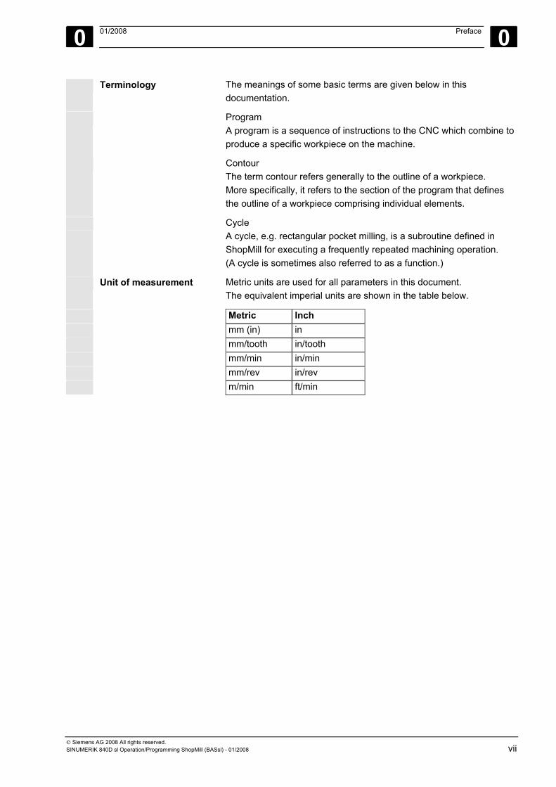
Unit of measurement Metric units are used for all parameters in this document. The equivalent imperial units are shown in the table below.
Metric Inch mm (in) in mm/tooth in/tooth mm/min in/min mm/rev in/rev m/min ft/min
0 Preface 01/2008
0
© Siemens AG 2008 All rights reserved. viii SINUMERIK 840D sl Operation/Programming ShopMill (BASsl) - 01/2008
Notes
0 01/2008 Contents 0
© Siemens AG 2008 All rights reserved. SINUMERIK 840D sl Operation/Programming ShopMill (BASsl) - 01/2008 ix
Contents Introduction 1-17
1.1 ShopMill .................................................................................................................... 1-18 1.1.1 Work sequence ......................................................................................................... 1-19
1.2 Workstation ............................................................................................................... 1-20 1.2.1 Coordinate system.................................................................................................... 1-21 1.2.2 Operator panels ........................................................................................................ 1-22 1.2.3 Operator panel keys.................................................................................................. 1-23 1.2.4 Machine control panels ............................................................................................. 1-25 1.2.5 Machine control panel elements ............................................................................... 1-25 1.2.6 Mini hand-held device ............................................................................................... 1-29
1.3 User interface............................................................................................................ 1-31 1.3.1 Overview ................................................................................................................... 1-31 1.3.2 Operation via softkeys and keys............................................................................... 1-34 1.3.3 Program views .......................................................................................................... 1-38 1.3.4 Entering parameters ................................................................................................. 1-42
1.4 Fundamentals ........................................................................................................... 1-44 1.4.1 Plane designations.................................................................................................... 1-44 1.4.2 Polar coordinates ...................................................................................................... 1-44 1.4.3 Absolute dimensions................................................................................................. 1-45 1.4.4 Incremental dimension.............................................................................................. 1-45 1.4.5 Pocket calculator mode............................................................................................. 1-46
Operation 2-47
2.1 Switching on and off.................................................................................................. 2-49
2.2 Approaching a reference point.................................................................................. 2-49 2.2.1 User agreement with Safety Integrated .................................................................... 2-51
2.3 Displaying axes......................................................................................................... 2-52
2.4 Operating modes ...................................................................................................... 2-53
2.5 Settings for the machine ........................................................................................... 2-54 2.5.1 Switching between units of measurement (millimeters/inches)................................ 2-54 2.5.2 Switching the coordinate system (MCS/WCS) ......................................................... 2-55
2.6 Setting a new position value ..................................................................................... 2-56
2.7 Measuring the workpiece zero.................................................................................. 2-58 2.7.1 Measuring an edge ................................................................................................... 2-62 2.7.2 Measuring a corner ................................................................................................... 2-67 2.7.3 Measuring pockets and holes ................................................................................... 2-69 2.7.4 Measuring a spigot.................................................................................................... 2-76 2.7.5 Aligning aplane ......................................................................................................... 2-83 2.7.6 Corrections after measurement of the zero point ..................................................... 2-85 2.7.7 Calibrating electronic probes .................................................................................... 2-86
0 Contents 01/2008
0
© Siemens AG 2008 All rights reserved. x SINUMERIK 840D sl Operation/Programming ShopMill (BASsl) - 01/2008
2.8 Measuring a tool........................................................................................................2-88 2.8.1 Measuring a tool manually ........................................................................................2-88 2.8.2 Calibrating a fixed point.............................................................................................2-92 2.8.3 Measuring a tool with a probe...................................................................................2-93 2.8.4 Calibrating probes .....................................................................................................2-96
2.9 Manual mode.............................................................................................................2-97 2.9.1 Selecting a tool and attaching it to the spindle..........................................................2-97 2.9.2 Entering a tool in the list and attaching it to the spindle............................................2-98 2.9.3 Entering a new tool in the list and loading it in the magazine ...................................2-99 2.9.4 Starting, stopping, and positioning a spindle manually.............................................2-99 2.9.5 Traversing axes.......................................................................................................2-101 2.9.6 Positioning axes ......................................................................................................2-103 2.9.7 Swiveling .................................................................................................................2-103 2.9.8 Face milling .............................................................................................................2-107 2.9.9 Settings for manual mode .......................................................................................2-108
2.10 MDA mode ..............................................................................................................2-111
2.11 Automatic mode ......................................................................................................2-112 2.11.1 Switchover between "T, F, S", "G functions", and "Auxiliary functions" displays....2-113 2.11.2 Selecting a program for execution ..........................................................................2-114 2.11.3 Starting/stopping/aborting a program......................................................................2-115 2.11.4 Interrupting a program.............................................................................................2-116 2.11.5 Starting execution at a specific program point ........................................................2-117 2.11.6 Controlling the program sequence..........................................................................2-122 2.11.7 Overstoring..............................................................................................................2-124 2.11.8 Testing a program ...................................................................................................2-125 2.11.9 Simultaneous recording before machining..............................................................2-126 2.11.10 Simultaneous recording during machining..............................................................2-128
2.12 Program trial run......................................................................................................2-129 2.12.1 Single block .............................................................................................................2-129 2.12.2 Displaying the current program block .....................................................................2-130 2.12.3 Correcting a program ..............................................................................................2-131
2.13 Run times ................................................................................................................2-132
2.14 Settings for automatic mode ...................................................................................2-134 2.14.1 Specifying the dry run feedrate ...............................................................................2-134 2.14.2 Parameterizing the workpiece counter....................................................................2-135
2.15 Tools and tool offsets ..............................................................................................2-136 2.15.1 Creating a new tool .................................................................................................2-143 2.15.2 Creating multiple cutting edges for each tool..........................................................2-145 2.15.3 Changing a tool name .............................................................................................2-146 2.15.4 Creating a replacement tool ....................................................................................2-146 2.15.5 Manual tools ............................................................................................................2-146 2.15.6 Tool offsets..............................................................................................................2-147 2.15.7 Miscellaneous functions for a tool...........................................................................2-150 2.15.8 Entering tool wear data ...........................................................................................2-151
0 01/2008 Contents 0
© Siemens AG 2008 All rights reserved. SINUMERIK 840D sl Operation/Programming ShopMill (BASsl) - 01/2008 xi
2.15.9 Activating tool monitoring........................................................................................ 2-152 2.15.10 Magazine list ........................................................................................................... 2-154 2.15.11 Deleting a tool ......................................................................................................... 2-155 2.15.12 Changing a tool type ............................................................................................... 2-155 2.15.13 Loading/unloading a tool into/out of the magazine ................................................. 2-156 2.15.14 Relocating a tool ..................................................................................................... 2-158 2.15.15 Positioning a magazine........................................................................................... 2-160 2.15.16 Sorting tools ............................................................................................................ 2-160
2.16 Zero offsets ............................................................................................................. 2-162 2.16.1 Defining zero offsets ............................................................................................... 2-164 2.16.2 Zero offset list ......................................................................................................... 2-165 2.16.3 Selecting/deselecting the work offset in the Manual area ...................................... 2-167
2.17 Switching to CNC-ISO mode .................................................................................. 2-168
2.18 ShopMill Open (PCU 50.3) ..................................................................................... 2-169
2.19 Remote diagnostics ................................................................................................ 2-169
Programming with ShopMill 3-171
3.1 Programming fundamentals.................................................................................... 3-173
3.2 Program structure ................................................................................................... 3-176
3.3 Creating a sequence program ................................................................................ 3-177
3.3.1 Creating a new program; defining a blank.............................................................. 3-177 3.3.2 Programming new blocks ....................................................................................... 3-181 3.3.3 Changing program blocks....................................................................................... 3-183 3.3.4 Program editor ........................................................................................................ 3-184 3.3.5 Specifying a quantity............................................................................................... 3-187
3.4 Programming the tool, offset value, and spindle speed.......................................... 3-188
3.5 Contour milling ........................................................................................................ 3-189 3.5.1 Representation of the contour ................................................................................ 3-192 3.5.2 Creating a new contour........................................................................................... 3-194 3.5.3 Creating contour elements...................................................................................... 3-196 3.5.4 Changing a contour................................................................................................. 3-201 3.5.5 Programming examples for freely defined contours ............................................... 3-203 3.5.6 Path milling.............................................................................................................. 3-207 3.5.7 Predrilling a contour pocket .................................................................................... 3-210 3.5.8 Milling a contour pocket (roughing)......................................................................... 3-213 3.5.9 Removing residual material from a contour pocket ................................................ 3-215 3.5.10 Finishing the contour pocket................................................................................... 3-217 3.5.11 Chamfering a contour pocket.................................................................................. 3-219 3.5.12 Milling a contour spigot (roughing).......................................................................... 3-220 3.5.13 Removing residual material from a contour spigot ................................................. 3-221 3.5.14 Finishing the contour spigot.................................................................................... 3-223 3.5.15 Chamfering a contour spigot................................................................................... 3-224
3.6 Linear or circular path motions ............................................................................... 3-225
0 Contents 01/2008
0
© Siemens AG 2008 All rights reserved. xii SINUMERIK 840D sl Operation/Programming ShopMill (BASsl) - 01/2008
3.6.1 Straight ....................................................................................................................3-225 3.6.2 Circle with known center point ................................................................................3-227 3.6.3 Circle with known radius .........................................................................................3-228 3.6.4 Helix ........................................................................................................................3-229 3.6.5 Polar coordinates ....................................................................................................3-230 3.6.6 Straight polar ...........................................................................................................3-231 3.6.7 Circle polar ..............................................................................................................3-232 3.6.8 Programming examples for polar coordinates ........................................................3-233
3.7 Drilling .....................................................................................................................3-234 3.7.1 Centering.................................................................................................................3-234 3.7.2 Drilling and reaming ................................................................................................3-235 3.7.3 Deep-hole drilling ....................................................................................................3-236 3.7.4 Boring ......................................................................................................................3-238 3.7.5 Tapping ...................................................................................................................3-239 3.7.6 Thread milling..........................................................................................................3-241 3.7.7 Drill and thread milling.............................................................................................3-245 3.7.8 Positioning on freely programmable positions and position patterns .....................3-247 3.7.9 Freely programmable positions...............................................................................3-248 3.7.10 Line position pattern................................................................................................3-252 3.7.11 Matrix position pattern.............................................................................................3-253 3.7.12 Box position pattern ................................................................................................3-254 3.7.13 Full circle position pattern .......................................................................................3-256 3.7.14 Pitch circle position pattern .....................................................................................3-258 3.7.15 Including and skipping positions .............................................................................3-260 3.7.16 Obstacle ..................................................................................................................3-261 3.7.17 Repeating positions.................................................................................................3-263 3.7.18 Programming examples for drilling .........................................................................3-264
3.8 Milling ......................................................................................................................3-266 3.8.1 Face milling .............................................................................................................3-266 3.8.2 Rectangular pocket .................................................................................................3-269 3.8.3 Circular pocket ........................................................................................................3-273 3.8.4 Rectangular spigot ..................................................................................................3-276 3.8.5 Circular spigot .........................................................................................................3-279 3.8.6 Longitudinal slot ......................................................................................................3-281 3.8.7 Circumferential slot .................................................................................................3-284 3.8.8 Open slot .................................................................................................................3-287 3.8.9 Use of position patterns for milling..........................................................................3-292 3.8.10 Engraving ................................................................................................................3-295
3.9 Measurement ..........................................................................................................3-300 3.9.1 Measuring the workpiece zero ................................................................................3-300 3.9.2 Measuring the tool...................................................................................................3-302 3.9.3 Calibrating the probe...............................................................................................3-304
3.10 Miscellaneous functions ..........................................................................................3-305 3.10.1 Calling a subroutine ................................................................................................3-305 3.10.2 Repeating program blocks ......................................................................................3-307
0 01/2008 Contents 0
© Siemens AG 2008 All rights reserved. SINUMERIK 840D sl Operation/Programming ShopMill (BASsl) - 01/2008 xiii
3.10.3 Changing program settings..................................................................................... 3-309 3.10.4 Calling zero offsets ................................................................................................. 3-309 3.10.5 Defining coordinate transformations ....................................................................... 3-311 3.10.6 Cylinder surface transformation.............................................................................. 3-314 3.10.7 Swiveling ................................................................................................................. 3-317 3.10.8 Miscellaneous functions.......................................................................................... 3-323
3.11 Inserting G code into the sequence program ......................................................... 3-324
Programming with G Code 4-327
4.1 Creating a G code program .................................................................................... 4-328
4.2 Executing a G code program .................................................................................. 4-331
4.3 G code editor .......................................................................................................... 4-333
4.4 Arithmetic variables................................................................................................. 4-337
4.5 ISO dialects............................................................................................................. 4-338
Simulation 5-339
5.1 General information ................................................................................................ 5-340
5.2 Starting/stopping a program in standard simulation ............................................... 5-341
5.3 Plan view representation......................................................................................... 5-343
5.4 3-plane view representation.................................................................................... 5-344
5.5 Enlarging the viewport ............................................................................................ 5-345
5.6 Three-dimensional representation.......................................................................... 5-346 5.6.1 Changing the position of the viewport..................................................................... 5-347 5.6.2 Cutting the workpiece ............................................................................................. 5-348
5.7 Starting/stopping the quick display for mold making .............................................. 5-349
5.8 Quick display representations................................................................................. 5-349
5.9 Adjusting and moving the workpiece graphics ....................................................... 5-351
5.10 Distance measurement ........................................................................................... 5-352
5.11 Search function ....................................................................................................... 5-353
5.12 Editing part program blocks .................................................................................... 5-354 5.12.1 Selecting G blocks .................................................................................................. 5-354 5.12.2 Editing a G code program....................................................................................... 5-355
File Management 6-357
6.1 Managing programs with ShopMill.......................................................................... 6-358
6.2 Managing programs with ShopMill on NCU (HMI Embedded sl) ........................... 6-359 6.2.1 Opening a program................................................................................................. 6-361 6.2.2 Executing a program............................................................................................... 6-362 6.2.3 Multiple clamping .................................................................................................... 6-362 6.2.4 Executing a G code program from the network drive ............................................. 6-365
0 Contents 01/2008
0
© Siemens AG 2008 All rights reserved. xiv SINUMERIK 840D sl Operation/Programming ShopMill (BASsl) - 01/2008
6.2.5 Creating a new directory/program...........................................................................6-366 6.2.6 Selecting several programs.....................................................................................6-367 6.2.7 Copying/Renaming a directory/program .................................................................6-368 6.2.8 Deleting a directory/program...................................................................................6-369 6.2.9 Saving/Reading in tool/zero point data ...................................................................6-370
6.3 Managing programs with PCU 50.3 (HMI Advanced).............................................6-373 6.3.1 Opening a program .................................................................................................6-375 6.3.2 Executing a program ...............................................................................................6-376 6.3.3 Multiple clamping.....................................................................................................6-376 6.3.4 Loading/Unloading a program.................................................................................6-379 6.3.5 Executing a G code program from a hard disk or floppy disk/network drive ..........6-380 6.3.6 Creating a new directory/program...........................................................................6-381 6.3.7 Selecting several programs.....................................................................................6-382 6.3.8 Copying/Renaming/Moving a directory/program ....................................................6-383 6.3.9 Deleting a directory/program...................................................................................6-385 6.3.10 Saving/Reading in tool/zero point data ...................................................................6-385
Mold making 7-389
7.1 Prerequisites ...........................................................................................................7-390
7.2 Setting up the machine ...........................................................................................7-392 7.2.1 Measuring a tool......................................................................................................7-392
7.3 Creating a program .................................................................................................7-393 7.3.1 Creating a program .................................................................................................7-393 7.3.2 Programming a tool .................................................................................................7-393 7.3.3 Programming the "High speed settings" cycle ........................................................7-393 7.3.4 Calling a subroutine ................................................................................................7-394
7.4 Executing a program ...............................................................................................7-397 7.4.1 Selecting a program for execution ..........................................................................7-397 7.4.2 Starting execution at a specific program point ........................................................7-398
7.5 Example ..................................................................................................................7-399
Interrupts and messages 8-403
8.1 Messages ................................................................................................................8-404
8.2 Alarms .....................................................................................................................8-404
8.3 User data.................................................................................................................8-405
8.4 Version display........................................................................................................8-407
Examples 9-409
9.1 Example 1: Machining with rectangular/circular pocket and circumferential slot ...9-410
9.2 Example 2: Translation and mirroring of a contour.................................................9-418
9.3 Example 3: Cylinder surface transformation ...........................................................9-421
9.4 Example 4: Slot side compensation........................................................................9-425
0 01/2008 Contents 0
© Siemens AG 2008 All rights reserved. SINUMERIK 840D sl Operation/Programming ShopMill (BASsl) - 01/2008 xv
9.5 Example 5: Swiveling.............................................................................................. 9-429
Appendix A-437
A Abbreviations ..........................................................................................................A-439
B Index ........................................................................................................................ I-441
0 Contents 01/2008
0
© Siemens AG 2008 All rights reserved. xvi SINUMERIK 840D sl Operation/Programming ShopMill (BASsl) - 01/2008
Notes
1 01/2008 Introduction 1
© Siemens AG 2008 All rights reserved. SINUMERIK 840D sl Operation/Programming ShopMill (BASsl) - 01/2008 1-17
Introduction 1.1 ShopMill .................................................................................................................... 1-18
1.1.1 Work sequence ......................................................................................................... 1-19
1.2 Workstation ............................................................................................................... 1-20 1.2.1 Coordinate system .................................................................................................... 1-21 1.2.2 Operator panels ........................................................................................................ 1-22 1.2.3 Operator panel keys.................................................................................................. 1-23 1.2.4 Machine control panels ............................................................................................. 1-25 1.2.5 Machine control panel elements ............................................................................... 1-25 1.2.6 Mini hand-held device ............................................................................................... 1-29
1.3 User interface............................................................................................................ 1-31 1.3.1 Overview ................................................................................................................... 1-31 1.3.2 Operation via softkeys and keys............................................................................... 1-34 1.3.3 Program views .......................................................................................................... 1-38 1.3.4 Entering parameters ................................................................................................. 1-42
1.4 Fundamentals ........................................................................................................... 1-44 1.4.1 Plane designations.................................................................................................... 1-44 1.4.2 Polar coordinates ...................................................................................................... 1-44 1.4.3 Absolute dimensions................................................................................................. 1-45 1.4.4 Incremental dimension.............................................................................................. 1-45 1.4.5 Pocket calculator mode............................................................................................. 1-46
1 Introduction 01/2008 1.1 ShopMill
1
© Siemens AG 2008 All rights reserved. 1-18 SINUMERIK 840D sl Operation/Programming ShopMill (BASsl) - 01/2008
1.1 ShopMill ShopMill is an operating and programming software program for
milling machines that makes it easy for you to operate a machine and to program workpieces.
These are some of the features the software provides:
Setting up the machine Special measurement cycles make it easier to measure the tools and the workpiece.
Creating a program 3 different programming methods are available: • G code programs for mold-making applications imported from
CAD/CAM systems. • G code programs that you create directly at the machine.
You can use all technology cycles for programming: • Sequence programs that you create directly at the machine
(software option). The workpiece is programmed with ease because graphical techniques are used and no knowledge of G codes is required. ShopMill displays the program as a clear, understandable work plan and presents the individual cycles and contour elements in a dynamic graphical display.
Irrespective of the programming method you use, the following functions will simplify programming and processing: • A powerful contour calculator lets you enter any contours. • A contour pocket cycle complete with detection of residual
material saves unnecessary machining (software option). • A swivel cycle allows multiple-surface machining and machining
on inclined surfaces, irrespective of the machine kinematics of the machine.
Program:execute You can display the execution of programs on the screen three-dimensionally. This makes it easy for you to check the result of programming and to observe the progress of workpiece machining at the machine (software option).
To execute a sequence program, you must have reading and writing rights.
The execution of sequence programs is a software option.
1 01/2008 Introduction1.1 ShopMill
1
© Siemens AG 2008 All rights reserved. SINUMERIK 840D sl Operation/Programming ShopMill (BASsl) - 01/2008 1-19
Tool management ShopMill stores your tool data. The software can also manage the
data for tools that are not in the tool magazine.
Program management Programs can be created simply by copying and modifying similar programs; there is no need to start again from the beginning.
With ShopMill you can implement multiple clamping of identical or different (software option) workpieces with optimization of the tool sequence.
You can access external programs from a network or from a diskette drive (software option).
1.1.1 Work sequence
Two typical working situations are considered separately in this Guide. • You want to execute a program for the purpose of automatically
machining a workpiece. • You want to create the program to be used for machining a
workpiece. Executing a program Before you execute a program, you have to set up your machine. You
must perform the following steps with the support of ShopMill (see Section "Operation"): • approach the reference point of the machine
(only for incremental position measuring systems) • tool measuring • define the workpiece zero • enter any other work offsets When you have finished setting up the machine, you can select a program and execute it automatically (see Section "Automatic operation").
1 Introduction 01/2008 1.2 Workstation
1
© Siemens AG 2008 All rights reserved. 1-20 SINUMERIK 840D sl Operation/Programming ShopMill (BASsl) - 01/2008
Creating a program As you create a new program, you can choose whether it will be a sequence program or a G code program (see "Creating a ShopMill program" or "G code program"). During creation of a sequence program, ShopMill prompts you to enterall the relevant parameters. Programming progress is automatically indicated in a dashed-line diagram. Help screens that explain the parameters in each operation also support you with programming. You can, of course, also insert G code commands in a sequence program. A G code program, however, must be created entirely out of G code commands.
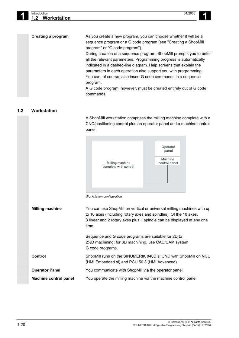
1.2 Workstation A ShopMill workstation comprises the milling machine complete with a
CNC/positioning control plus an operator panel and a machine control panel.
Milling machine complete with control
Operatorpanel
Machine control panel
Workstation configuration
Milling machine You can use ShopMill on vertical or universal milling machines with up to 10 axes (including rotary axes and spindles). Of the 10 axes, 3 linear and 2 rotary axes plus 1 spindle can be displayed at any one time.
Sequence and G code programs are suitable for 2D to 2½D machining; for 3D machining, use CAD/CAM system G code programs.
Control ShopMill runs on the SINUMERIK 840D sl CNC with ShopMill on NCU(HMI Embedded sl) and PCU 50.3 (HMI Advanced).
Operator Panel You communicate with ShopMill via the operator panel.
Machine control panel You operate the milling machine via the machine control panel.
1 01/2008 Introduction1.2 Workstation
1
© Siemens AG 2008 All rights reserved. SINUMERIK 840D sl Operation/Programming ShopMill (BASsl) - 01/2008 1-21
1.2.1 Coordinate system
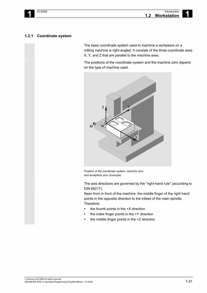
The basic coordinate system used to machine a workpiece on a milling machine is right-angled. It consists of the three coordinate axes X, Y, and Z that are parallel to the machine axes.
The positions of the coordinate system and the machine zero depend on the type of machine used.
Z
X
Y
M W
Position of the coordinate system, machine zero and workpiece zero (example)
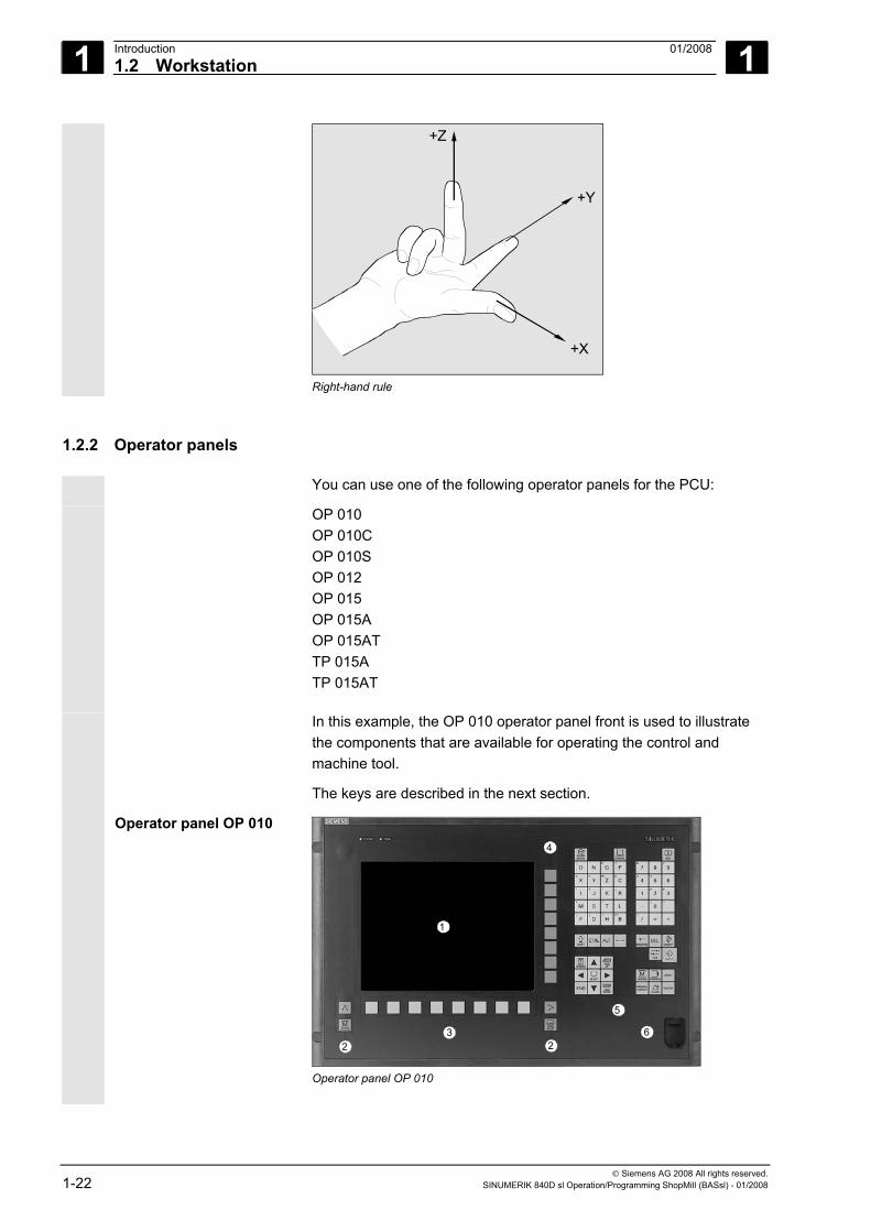
The axis directions are governed by the "right-hand rule" (according to DIN 66217). Seen from in front of the machine, the middle finger of the right hand points in the opposite direction to the infeed of the main spindle. Therefore: • the thumb points in the +X direction • the index finger points in the +Y direction • the middle finger points in the +Z direction
1 Introduction 01/2008 1.2 Workstation
1
© Siemens AG 2008 All rights reserved. 1-22 SINUMERIK 840D sl Operation/Programming ShopMill (BASsl) - 01/2008
+Z
+Y
+X
Right-hand rule
1.2.2 Operator panels
You can use one of the following operator panels for the PCU:
OP 010 OP 010C OP 010S OP 012 OP 015 OP 015A OP 015AT TP 015A TP 015AT
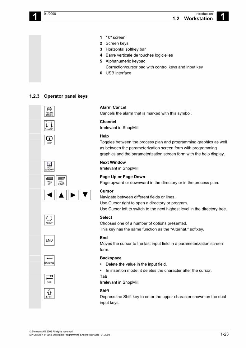
In this example, the OP 010 operator panel front is used to illustrate the components that are available for operating the control and machine tool.
The keys are described in the next section.
Operator panel OP 010
3
4
2
1
6
.
5
2
Operator panel OP 010
1 01/2008 Introduction1.2 Workstation
1
© Siemens AG 2008 All rights reserved. SINUMERIK 840D sl Operation/Programming ShopMill (BASsl) - 01/2008 1-23
1 10" screen 2 Screen keys 3 Horizontal softkey bar 4 Barre verticale de touches logicielles 5 Alphanumeric keypad
Correction/cursor pad with control keys and input key 6 USB interface
1.2.3 Operator panel keys
Alarm Cancel Cancels the alarm that is marked with this symbol.
Channel Irrelevant in ShopMill.
Help Toggles between the process plan and programming graphics as well as between the parameterization screen form with programming graphics and the parameterization screen form with the help display.
Next Window Irrelevant in ShopMill.
Page Up or Page Down Page upward or downward in the directory or in the process plan.
Cursor Navigate between different fields or lines. Use Cursor right to open a directory or program. Use Cursor left to switch to the next highest level in the directory tree.
Select Chooses one of a number of options presented. This key has the same function as the "Alternat." softkey.
End Moves the cursor to the last input field in a parameterization screen form.
Backspace • Delete the value in the input field. • In insertion mode, it deletes the character after the cursor.
Tab Irrelevant in ShopMill.
Shift Depress the Shift key to enter the upper character shown on the dual input keys.
1 Introduction 01/2008 1.2 Workstation
1
© Siemens AG 2008 All rights reserved. 1-24 SINUMERIK 840D sl Operation/Programming ShopMill (BASsl) - 01/2008
Ctrl Use the following key combinations to navigate in the process plan and in the G code editor: • Ctrl + Pos1: Jump to the beginning. • Ctrl + End: Jump to the end.
Old Irrelevant in ShopMill.
Del - not with OP 031 • Deletes the value in the parameter field. • In insertion mode, it deletes the character marked by the cursor.
Insert Activates insertion mode or the pocket calculator.
Input • Terminates entry of a value in the input field. • Opens a directory or program.
Alarm - only OP 010 and OP 010C Opens the "Messages/Alarms" operating area. This key has the same function as the "Alarm list" softkey.
Program - only OP 010 and OP 010C Opens the "Program" operating area. This key has the same function as the "Prog. edit" softkey.
Offset - only OP 010 and OP 010C Opens the "Tools/Offsets" operating area. This key has the same function as the "Tool zero point" softkey
Program Manager - only OP 010 and OP 010C Opens the "Program Manager" operating area. This key has the same function as the "Program" softkey.
1 01/2008 Introduction1.2 Workstation
1
© Siemens AG 2008 All rights reserved. SINUMERIK 840D sl Operation/Programming ShopMill (BASsl) - 01/2008 1-25
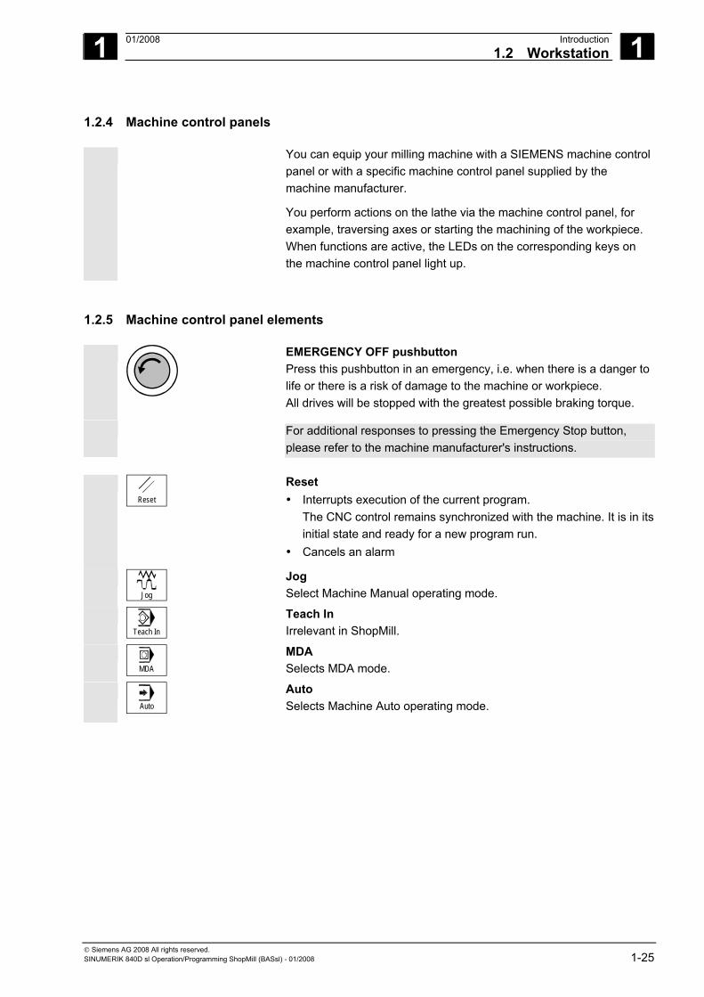
1.2.4 Machine control panels
You can equip your milling machine with a SIEMENS machine control panel or with a specific machine control panel supplied by the machine manufacturer.
You perform actions on the lathe via the machine control panel, for example, traversing axes or starting the machining of the workpiece. When functions are active, the LEDs on the corresponding keys on the machine control panel light up.
1.2.5 Machine control panel elements
EMERGENCY OFF pushbutton Press this pushbutton in an emergency, i.e. when there is a danger to life or there is a risk of damage to the machine or workpiece. All drives will be stopped with the greatest possible braking torque.
For additional responses to pressing the Emergency Stop button, please refer to the machine manufacturer's instructions.
Reset
Reset • Interrupts execution of the current program.
The CNC control remains synchronized with the machine. It is in its initial state and ready for a new program run.
• Cancels an alarm
Jog
Jog Select Machine Manual operating mode.
Teach In
Teach In Irrelevant in ShopMill.
MDA
MDA Selects MDA mode.
Auto
Auto Selects Machine Auto operating mode.
1 Introduction 01/2008 1.2 Workstation
1
© Siemens AG 2008 All rights reserved. 1-26 SINUMERIK 840D sl Operation/Programming ShopMill (BASsl) - 01/2008
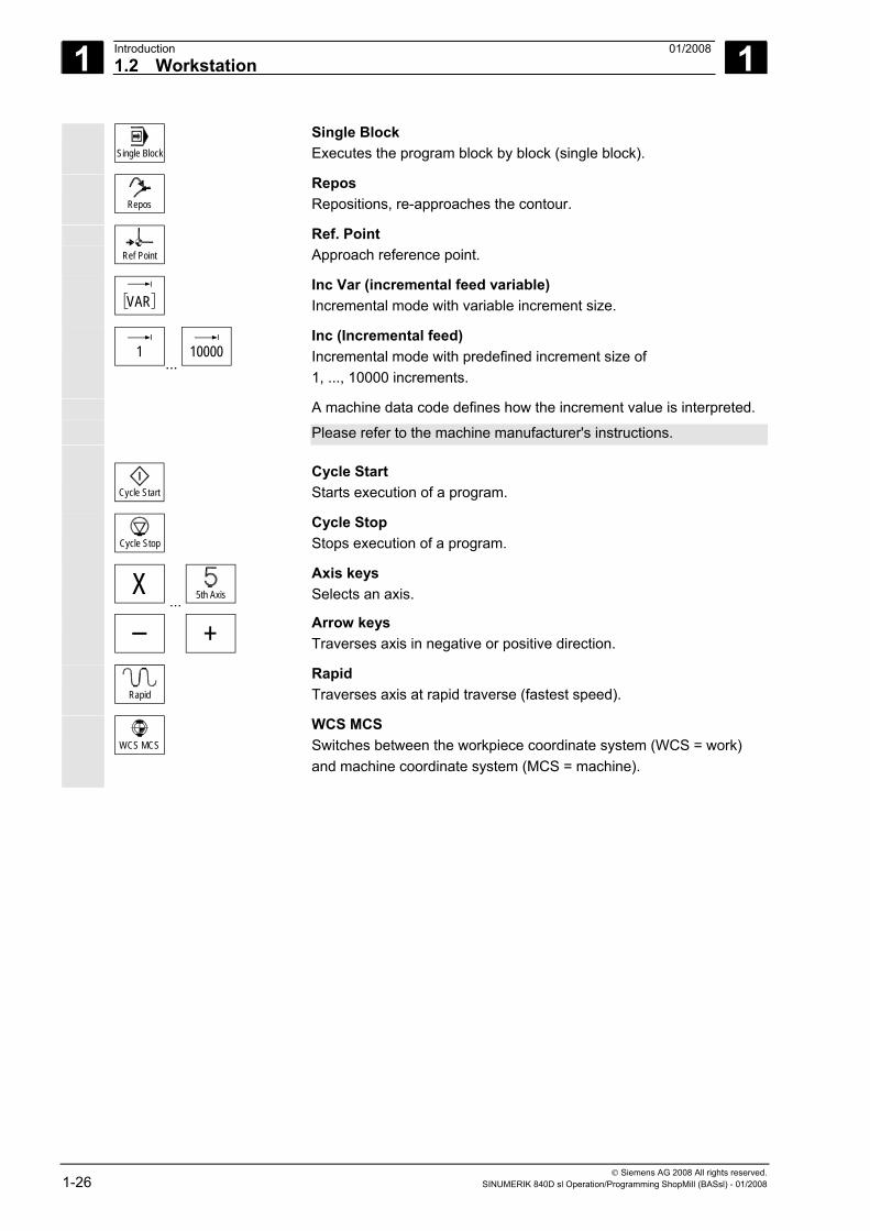
Single Block
Single Block Executes the program block by block (single block).
Repos
Repos Repositions, re-approaches the contour.
Ref Point
Ref. Point Approach reference point.
VAR
Inc Var (incremental feed variable) Incremental mode with variable increment size.
1
... 10000
Inc (Incremental feed) Incremental mode with predefined increment size of 1, ..., 10000 increments.
A machine data code defines how the increment value is interpreted. Please refer to the machine manufacturer's instructions.
Cycle Start
Cycle Start Starts execution of a program.
Cycle Stop
Cycle Stop Stops execution of a program.
X ... 5th Axis
Axis keys Selects an axis.
+
Arrow keys Traverses axis in negative or positive direction.
Rapid
Rapid Traverses axis at rapid traverse (fastest speed).
WCS MCS
WCS MCS Switches between the workpiece coordinate system (WCS = work) and machine coordinate system (MCS = machine).
1 01/2008 Introduction1.2 Workstation
1
© Siemens AG 2008 All rights reserved. SINUMERIK 840D sl Operation/Programming ShopMill (BASsl) - 01/2008 1-27
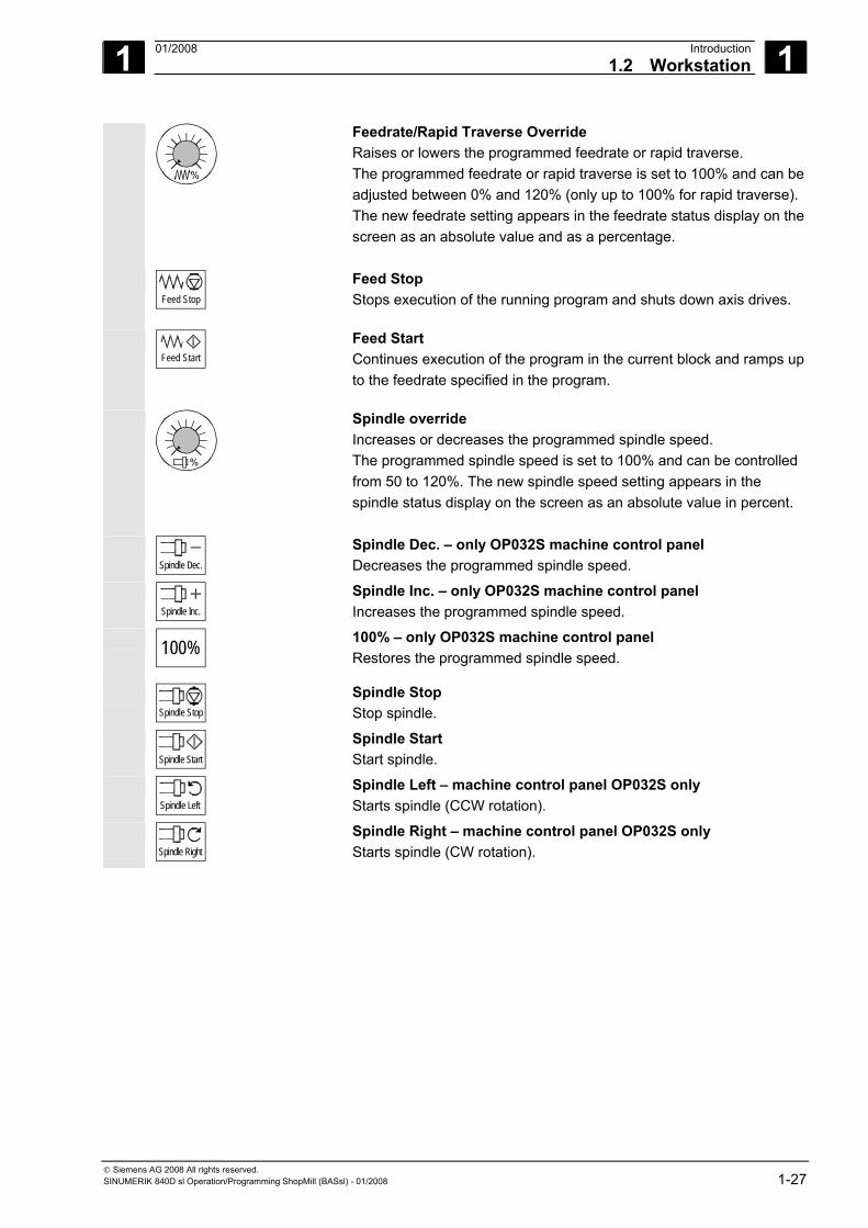
%
Feedrate/Rapid Traverse Override Raises or lowers the programmed feedrate or rapid traverse. The programmed feedrate or rapid traverse is set to 100% and can be adjusted between 0% and 120% (only up to 100% for rapid traverse). The new feedrate setting appears in the feedrate status display on the screen as an absolute value and as a percentage.
Feed Stop
Feed Stop Stops execution of the running program and shuts down axis drives.
Feed Start
Feed Start Continues execution of the program in the current block and ramps up to the feedrate specified in the program.
%
Spindle override Increases or decreases the programmed spindle speed. The programmed spindle speed is set to 100% and can be controlled from 50 to 120%. The new spindle speed setting appears in the spindle status display on the screen as an absolute value in percent.
Spindle Dec.
Spindle Dec. – only OP032S machine control panel Decreases the programmed spindle speed.
Spindle Inc.
Spindle Inc. – only OP032S machine control panel Increases the programmed spindle speed.
100%
100% – only OP032S machine control panel Restores the programmed spindle speed.
Spindle Stop
Spindle Stop Stop spindle.
Spindle Start
Spindle Start Start spindle.
Spindle Left
Spindle Left – machine control panel OP032S only Starts spindle (CCW rotation).
Spindle Right
Spindle Right – machine control panel OP032S only Starts spindle (CW rotation).
1 Introduction 01/2008 1.2 Workstation
1
© Siemens AG 2008 All rights reserved. 1-28 SINUMERIK 840D sl Operation/Programming ShopMill (BASsl) - 01/2008
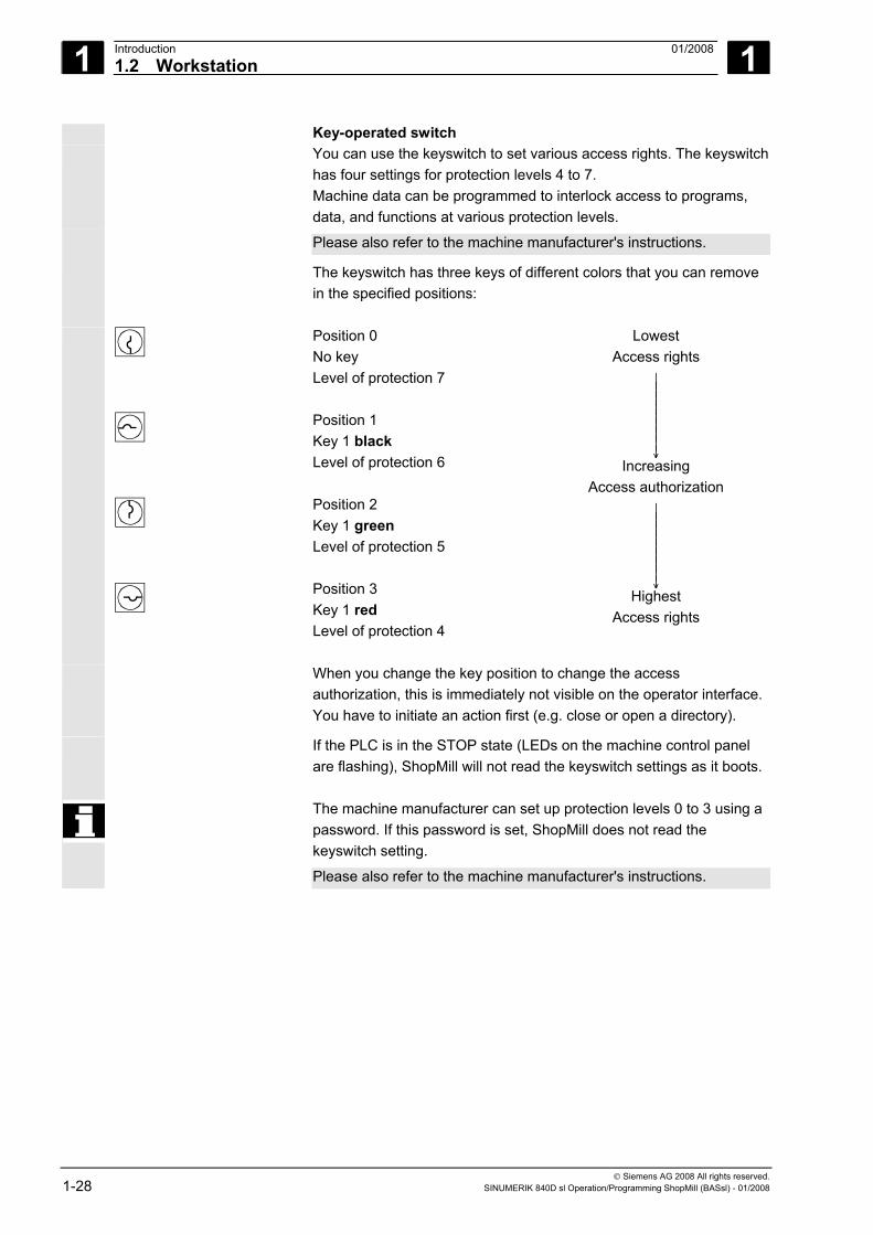
Key-operated switch You can use the keyswitch to set various access rights. The keyswitch
has four settings for protection levels 4 to 7. Machine data can be programmed to interlock access to programs, data, and functions at various protection levels.
Please also refer to the machine manufacturer's instructions. The keyswitch has three keys of different colors that you can remove
in the specified positions:
Position 0 No key Level of protection 7 Position 1 Key 1 black Level of protection 6 Position 2 Key 1 green Level of protection 5 Position 3 Key 1 red Level of protection 4
Lowest Access rights
⏐ ⏐ ⏐ ⏐ ⏐ ⏐ ⏐ ⏐ ↓
Increasing Access authorization
⏐ ⏐ ⏐ ⏐ ⏐ ⏐ ⏐ ⏐ ↓
Highest Access rights
When you change the key position to change the access authorization, this is immediately not visible on the operator interface. You have to initiate an action first (e.g. close or open a directory).
If the PLC is in the STOP state (LEDs on the machine control panel are flashing), ShopMill will not read the keyswitch settings as it boots.
The machine manufacturer can set up protection levels 0 to 3 using a password. If this password is set, ShopMill does not read the keyswitch setting.
Please also refer to the machine manufacturer's instructions.
1 01/2008 Introduction1.2 Workstation
1
© Siemens AG 2008 All rights reserved. SINUMERIK 840D sl Operation/Programming ShopMill (BASsl) - 01/2008 1-29
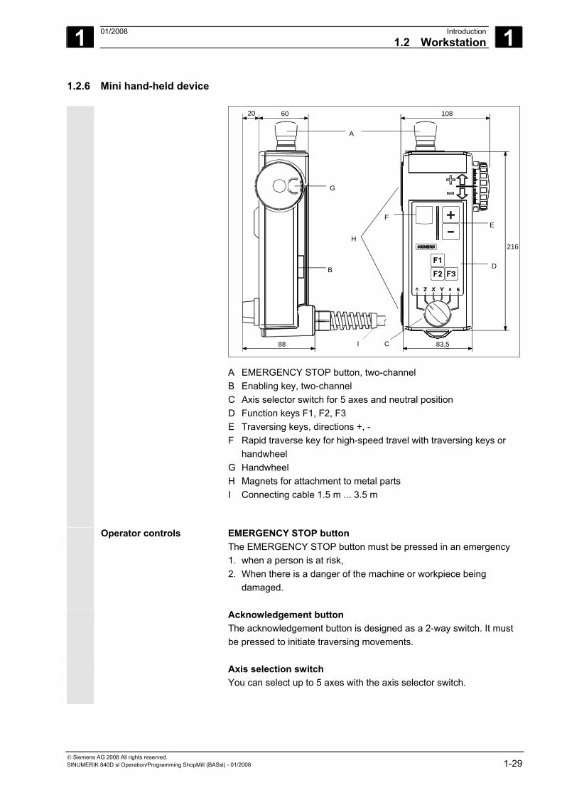
1.2.6 Mini hand-held device
A
B
C
H
D
F
G
E
I88 83,5
20 60 108
216
A EMERGENCY STOP button, two-channel B Enabling key, two-channel C Axis selector switch for 5 axes and neutral position D Function keys F1, F2, F3 E Traversing keys, directions +, - F Rapid traverse key for high-speed travel with traversing keys or handwheel G Handwheel H Magnets for attachment to metal parts I Connecting cable 1.5 m ... 3.5 m
Operator controls EMERGENCY STOP button The EMERGENCY STOP button must be pressed in an emergency 1. when a person is at risk, 2. When there is a danger of the machine or workpiece being
damaged.
Acknowledgement button The acknowledgement button is designed as a 2-way switch. It must be pressed to initiate traversing movements.
Axis selection switch You can select up to 5 axes with the axis selector switch.
1 Introduction 01/2008 1.2 Workstation
1
© Siemens AG 2008 All rights reserved. 1-30 SINUMERIK 840D sl Operation/Programming ShopMill (BASsl) - 01/2008
Function keys The function keys can be used to trigger machine-specific functions.
Traversing keys The +, - traversing keys can be used to trigger traversing movements on the axis selected via the axis selection switch.
Handwheel The handwheel can be used to initiate movements at the selected axis using the axis selection switch. The handwheel supplies two guide signals with 100 I/U.
Rapid traverse key The rapid traverse key increases the traversing speed of the axis selected with the axis selector switch. The rapid traverse key acts bothon travel commands from the +/- keys and on the handwheel signals.
1 01/2008 Introduction1.3 User interface
1
© Siemens AG 2008 All rights reserved. SINUMERIK 840D sl Operation/Programming ShopMill (BASsl) - 01/2008 1-31
1.3 User interface
1.3.1 Overview
Screen layout
1211
10
9 13
87
65 4
3
21
14
14
15 15
User interface
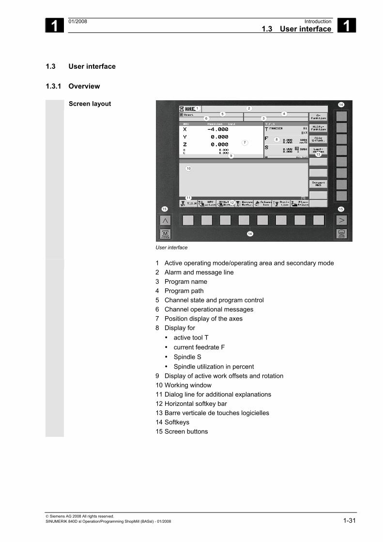
1 Active operating mode/operating area and secondary mode 2 Alarm and message line 3 Program name 4 Program path 5 Channel state and program control 6 Channel operational messages 7 Position display of the axes 8 Display for
• active tool T • current feedrate F • Spindle S • Spindle utilization in percent
9 Display of active work offsets and rotation 10 Working window 11 Dialog line for additional explanations 12 Horizontal softkey bar 13 Barre verticale de touches logicielles 14 Softkeys 15 Screen buttons
1 Introduction 01/2008 1.3 User interface
1
© Siemens AG 2008 All rights reserved. 1-32 SINUMERIK 840D sl Operation/Programming ShopMill (BASsl) - 01/2008
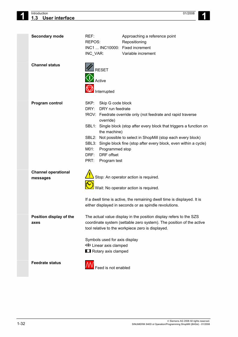
Secondary mode REF: Approaching a reference point REPOS: Repositioning INC1 ... INC10000: Fixed increment INC_VAR: Variable increment
Channel status RESET
Active
Interrupted
Program control SKP: Skip G code block DRY: DRY run feedrate !ROV: Feedrate override only (not feedrate and rapid traverse
override) SBL1: Single block (stop after every block that triggers a function on
the machine) SBL2: Not possible to select in ShopMill (stop each every block) SBL3: Single block fine (stop after every block, even within a cycle) M01: Programmed stop DRF: DRF offset PRT: Program test
Channel operational messages Stop: An operator action is required.
Wait: No operator action is required. If a dwell time is active, the remaining dwell time is displayed. It is either displayed in seconds or as spindle revolutions.
Position display of the axes
The actual value display in the position display refers to the SZS coordinate system (settable zero system). The position of the active tool relative to the workpiece zero is displayed. Symbols used for axis display
Linear axis clamped Rotary axis clamped
Feedrate status
Feed is not enabled
1 01/2008 Introduction1.3 User interface
1
© Siemens AG 2008 All rights reserved. SINUMERIK 840D sl Operation/Programming ShopMill (BASsl) - 01/2008 1-33
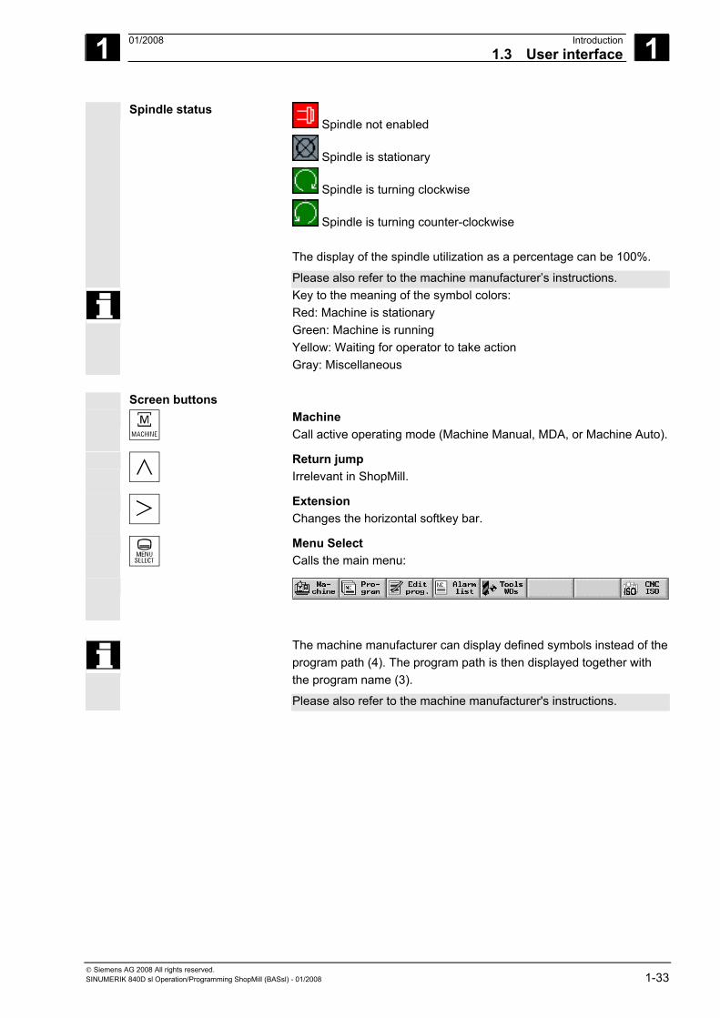
Spindle status Spindle not enabled
Spindle is stationary
Spindle is turning clockwise
Spindle is turning counter-clockwise The display of the spindle utilization as a percentage can be 100%.
Please also refer to the machine manufacturer’s instructions. Key to the meaning of the symbol colors:
Red: Machine is stationary Green: Machine is running Yellow: Waiting for operator to take action Gray: Miscellaneous
Screen buttons
Machine Call active operating mode (Machine Manual, MDA, or Machine Auto).
Return jump Irrelevant in ShopMill.
Extension Changes the horizontal softkey bar.
Menu Select Calls the main menu:
The machine manufacturer can display defined symbols instead of the program path (4). The program path is then displayed together with the program name (3).
Please also refer to the machine manufacturer's instructions.
1 Introduction 01/2008 1.3 User interface
1
© Siemens AG 2008 All rights reserved. 1-34 SINUMERIK 840D sl Operation/Programming ShopMill (BASsl) - 01/2008
1.3.2 Operation via softkeys and keys
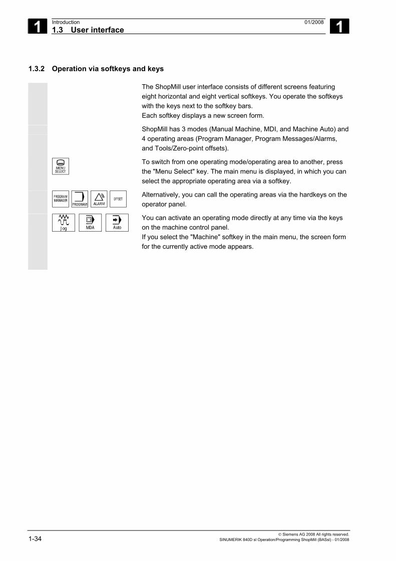
The ShopMill user interface consists of different screens featuring eight horizontal and eight vertical softkeys. You operate the softkeys with the keys next to the softkey bars. Each softkey displays a new screen form.
ShopMill has 3 modes (Manual Machine, MDI, and Machine Auto) and 4 operating areas (Program Manager, Program Messages/Alarms, and Tools/Zero-point offsets).
To switch from one operating mode/operating area to another, press the "Menu Select" key. The main menu is displayed, in which you can select the appropriate operating area via a softkey.
Alternatively, you can call the operating areas via the hardkeys on the operator panel.
Jog MDA Auto
You can activate an operating mode directly at any time via the keys on the machine control panel. If you select the "Machine" softkey in the main menu, the screen form for the currently active mode appears.
1 01/2008 Introduction1.3 User interface
1
© Siemens AG 2008 All rights reserved. SINUMERIK 840D sl Operation/Programming ShopMill (BASsl) - 01/2008 1-35
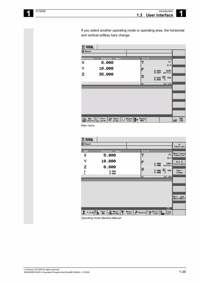
If you select another operating mode or operating area, the horizontal and vertical softkey bars change.
Main menu
4
Operating mode Machine Manual
1 Introduction 01/2008 1.3 User interface
1
© Siemens AG 2008 All rights reserved. 1-36 SINUMERIK 840D sl Operation/Programming ShopMill (BASsl) - 01/2008
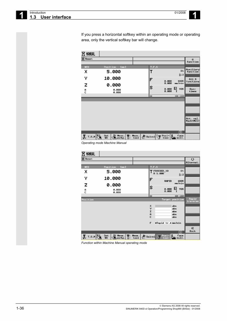
If you press a horizontal softkey within an operating mode or operating area, only the vertical softkey bar will change.
4
Operating mode Machine Manual
Function within Machine Manual operating mode
1 01/2008 Introduction1.3 User interface
1
© Siemens AG 2008 All rights reserved. SINUMERIK 840D sl Operation/Programming ShopMill (BASsl) - 01/2008 1-37
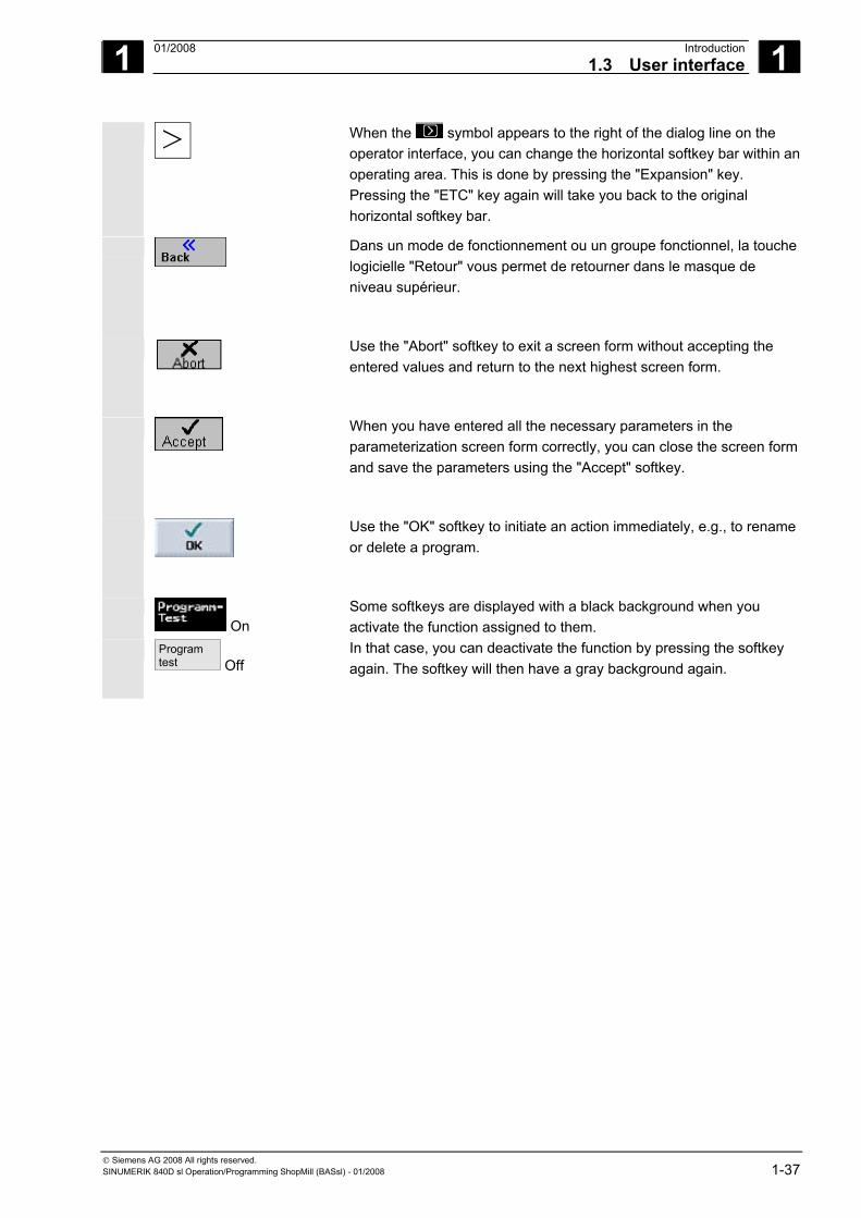
When the symbol appears to the right of the dialog line on the operator interface, you can change the horizontal softkey bar within an operating area. This is done by pressing the "Expansion" key. Pressing the "ETC" key again will take you back to the original horizontal softkey bar.
Dans un mode de fonctionnement ou un groupe fonctionnel, la touche logicielle "Retour" vous permet de retourner dans le masque de niveau supérieur.
Use the "Abort" softkey to exit a screen form without accepting the entered values and return to the next highest screen form.
When you have entered all the necessary parameters in the parameterization screen form correctly, you can close the screen form and save the parameters using the "Accept" softkey.
Use the "OK" softkey to initiate an action immediately, e.g., to rename or delete a program.
On
Some softkeys are displayed with a black background when you activate the function assigned to them.
Program test Off
In that case, you can deactivate the function by pressing the softkey again. The softkey will then have a gray background again.
1 Introduction 01/2008 1.3 User interface
1
© Siemens AG 2008 All rights reserved. 1-38 SINUMERIK 840D sl Operation/Programming ShopMill (BASsl) - 01/2008
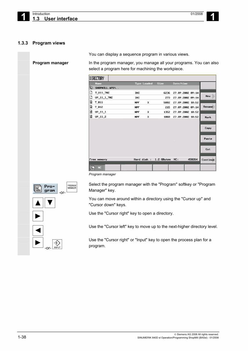
1.3.3 Program views
You can display a sequence program in various views.
Program manager In the program manager, you manage all your programs. You can also select a program here for machining the workpiece.
Program manager
-or-
Select the program manager with the "Program" softkey or "Program Manager" key.
You can move around within a directory using the "Cursor up" and "Cursor down" keys.
Use the "Cursor right" key to open a directory.
Use the "Cursor left" key to move up to the next-higher directory level.
-or-
Use the "Cursor right" or "Input" key to open the process plan for a program.
1 01/2008 Introduction1.3 User interface
1
© Siemens AG 2008 All rights reserved. SINUMERIK 840D sl Operation/Programming ShopMill (BASsl) - 01/2008 1-39
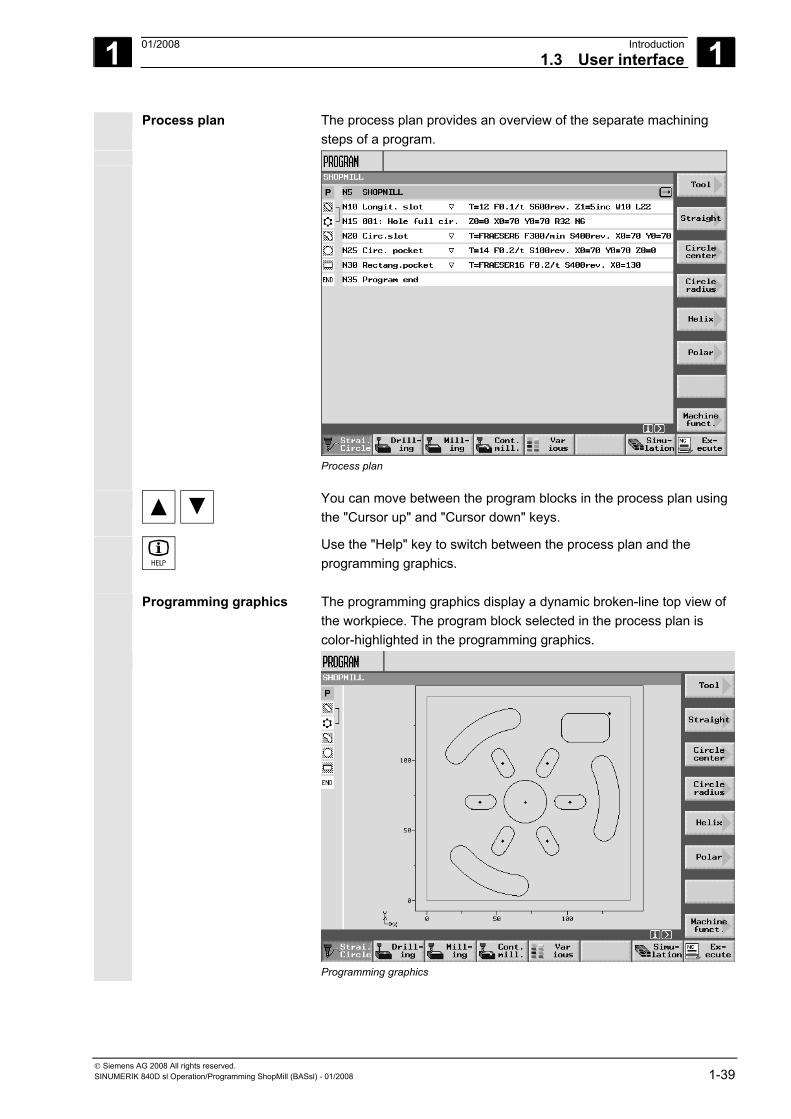
Process plan The process plan provides an overview of the separate machining steps of a program.
Process plan
You can move between the program blocks in the process plan using the "Cursor up" and "Cursor down" keys.
Use the "Help" key to switch between the process plan and the programming graphics.
Programming graphics The programming graphics display a dynamic broken-line top view of the workpiece. The program block selected in the process plan is color-highlighted in the programming graphics.
Programming graphics
1 Introduction 01/2008 1.3 User interface
1
© Siemens AG 2008 All rights reserved. 1-40 SINUMERIK 840D sl Operation/Programming ShopMill (BASsl) - 01/2008
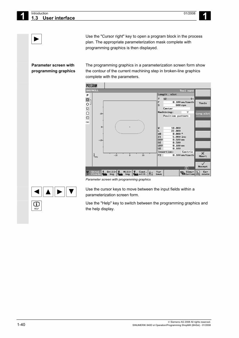
Use the "Cursor right" key to open a program block in the process plan. The appropriate parameterization mask complete with programming graphics is then displayed.
Parameter screen with programming graphics
The programming graphics in a parameterization screen form show the contour of the current machining step in broken-line graphics complete with the parameters.
Parameter screen with programming graphics
Use the cursor keys to move between the input fields within a parameterization screen form.
Use the "Help" key to switch between the programming graphics and the help display.
1 01/2008 Introduction1.3 User interface
1
© Siemens AG 2008 All rights reserved. SINUMERIK 840D sl Operation/Programming ShopMill (BASsl) - 01/2008 1-41
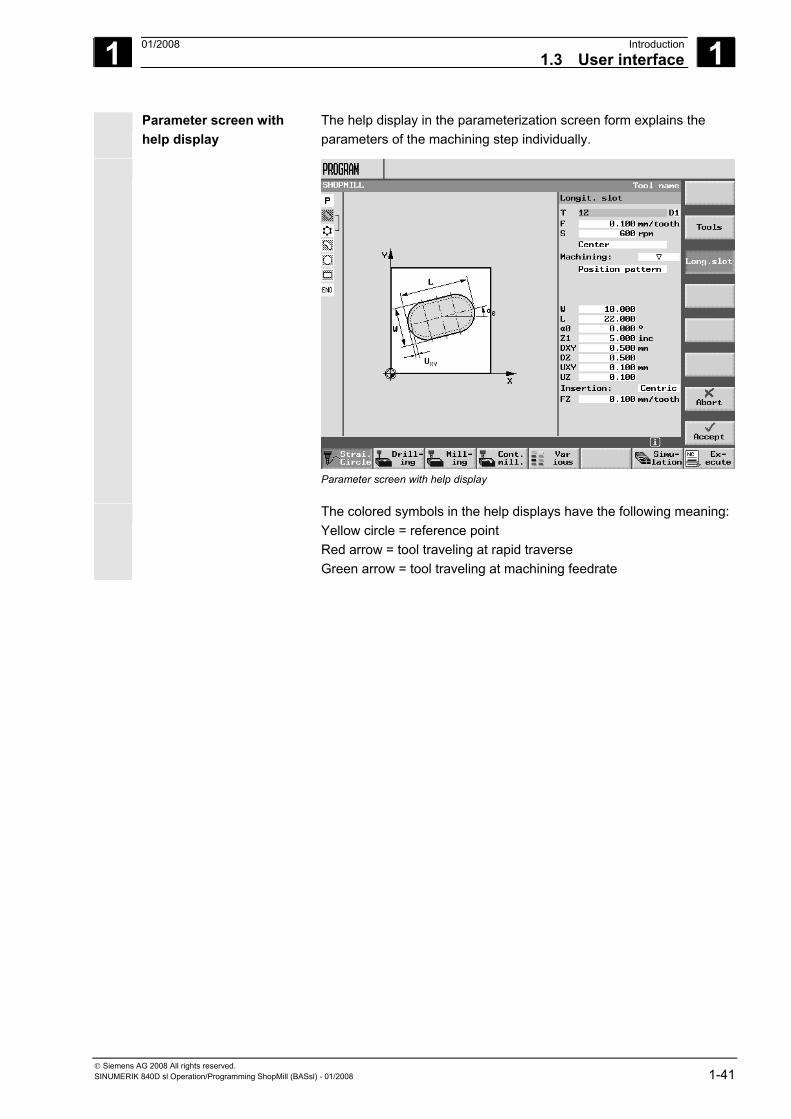
Parameter screen with help display
The help display in the parameterization screen form explains the parameters of the machining step individually.
Parameter screen with help display
The colored symbols in the help displays have the following meaning:Yellow circle = reference point Red arrow = tool traveling at rapid traverse Green arrow = tool traveling at machining feedrate
1 Introduction 01/2008 1.3 User interface
1
© Siemens AG 2008 All rights reserved. 1-42 SINUMERIK 840D sl Operation/Programming ShopMill (BASsl) - 01/2008
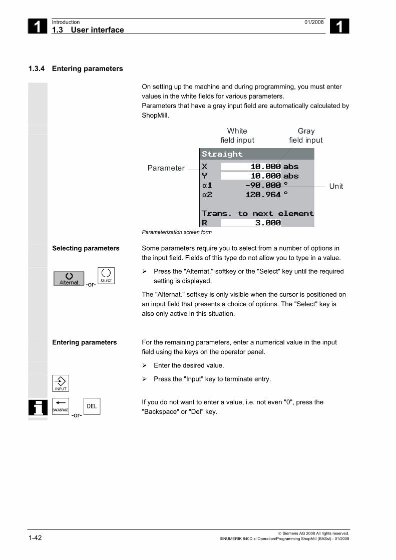
1.3.4 Entering parameters
On setting up the machine and during programming, you must enter values in the white fields for various parameters. Parameters that have a gray input field are automatically calculated by ShopMill.
Parameter
White field input
Unit
Gray field input
Parameterization screen form
Selecting parameters
Some parameters require you to select from a number of options in the input field. Fields of this type do not allow you to type in a value.
-or-
Press the "Alternat." softkey or the "Select" key until the required setting is displayed.
The "Alternat." softkey is only visible when the cursor is positioned on an input field that presents a choice of options. The "Select" key is also only active in this situation.
Entering parameters
For the remaining parameters, enter a numerical value in the input field using the keys on the operator panel.
Enter the desired value.
Press the "Input" key to terminate entry.
-or-
If you do not want to enter a value, i.e. not even "0", press the "Backspace" or "Del" key.
1 01/2008 Introduction1.3 User interface
1
© Siemens AG 2008 All rights reserved. SINUMERIK 840D sl Operation/Programming ShopMill (BASsl) - 01/2008 1-43
Selecting the unit
For certain parameters, you can choose between different units.
-or-
Press the "Alternat." softkey or the "Select" key until the required unit is displayed.
The "Alternat." softkey is only visible when you have a choice of units for this parameter. The "Select" key is also only active in this situation.
Deleting parameters
If an input field contains an invalid value, you can delete it completely.
-or-
Press the "Backspace" or "Del" key.
Changing or calculating parameters
If you only want to change individual characters in an input field rather than overwriting the entire entry, switch to insertion mode. In this mode, the pocket calculator is also active. You can use it during programming to calculate parameter values.
Press the "Insert" key.
Insertion mode and the pocket calculator are activated.
You can navigate within the input field using the "Left cursor" and "Right cursor" keys. Use the "Backspace" or "Del" key to delete individual characters.
For more information on the pocket calculator, see Section "Pocket calculator".
Accepting parameters
When you have correctly entered all the necessary parameters in the parameterization screen form, you can close the screen form and save the parameters.
-or-
Press the "Accept" softkey or the "Cursor left" key. If there are several input fields in a line and you want to use the "Cursor left" key to accept the parameters, you must position the cursor in the leftmost input field.
You cannot accept the parameters if they are incomplete or obviously erroneous. In this case, you can see from the dialog line which parameters are missing or were entered incorrectly.
1 Introduction 01/2008 1.4 Fundamentals
1
© Siemens AG 2008 All rights reserved. 1-44 SINUMERIK 840D sl Operation/Programming ShopMill (BASsl) - 01/2008
1.4 Fundamentals
1.4.1 Plane designations
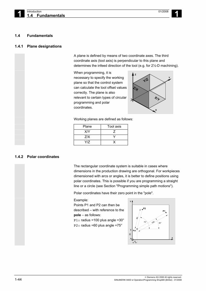
A plane is defined by means of two coordinate axes. The third coordinate axis (tool axis) is perpendicular to this plane and determines the infeed direction of the tool (e.g. for 2½-D machining).
When programming, it is necessary to specify the working plane so that the control system can calculate the tool offset values correctly. The plane is also relevant to certain types of circular programming and polar coordinates.
X
YZ
Y/Z
Z/X
X/Y
Working planes are defined as follows:
Plane Tool axis X/Y Z Z/X Y Y/Z X
1.4.2 Polar coordinates
The rectangular coordinate system is suitable in cases where dimensions in the production drawing are orthogonal. For workpieces dimensioned with arcs or angles, it is better to define positions using polar coordinates. This is possible if you are programming a straight line or a circle (see Section "Programming simple path motions").
Polar coordinates have their zero point in the "pole".
Example: Points P1 and P2 can then be described – with reference to the pole – as follows: P1: radius =100 plus angle =30° P2: radius =60 plus angle =75°
X
Y
P1P2
30°75°
Pol
15
30
60
100
1 01/2008 Introduction1.4 Fundamentals
1
© Siemens AG 2008 All rights reserved. SINUMERIK 840D sl Operation/Programming ShopMill (BASsl) - 01/2008 1-45
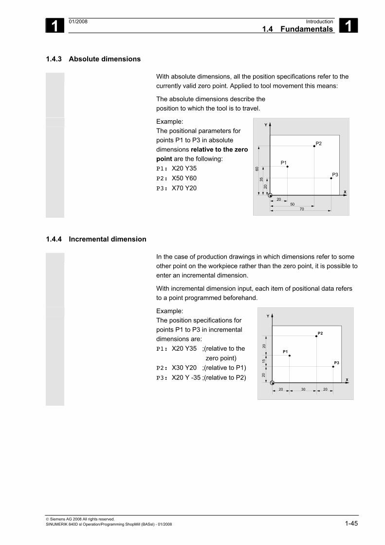
1.4.3 Absolute dimensions
With absolute dimensions, all the position specifications refer to the currently valid zero point. Applied to tool movement this means:
The absolute dimensions describe the position to which the tool is to travel.
Example: The positional parameters for points P1 to P3 in absolute dimensions relative to the zero point are the following: P1: X20 Y35 P2: X50 Y60 P3: X70 Y20
X
Y
7050
20
P2
P3
P1
6035
20
1.4.4 Incremental dimension
In the case of production drawings in which dimensions refer to some other point on the workpiece rather than the zero point, it is possible to enter an incremental dimension.
With incremental dimension input, each item of positional data refers to a point programmed beforehand.
Example: The position specifications for points P1 to P3 in incremental dimensions are: P1: X20 Y35 ;(relative to the zero point) P2: X30 Y20 ;(relative to P1) P3: X20 Y -35 ;(relative to P2)
X
Y
P1
20 2030
P2
P3
2015
20
1 Introduction 01/2008 1.4 Fundamentals
1
© Siemens AG 2008 All rights reserved. 1-46 SINUMERIK 840D sl Operation/Programming ShopMill (BASsl) - 01/2008
1.4.5 Pocket calculator mode
Function
Requirement The cursor is positioned on a parameter field.
=
Press the "Insert" key
or Equals key Switch to pocket calculator mode. Once you have pressed this key, enter one of the basic arithmetic operators (+, -, *, / ), then enter a value,
then press "Input", and then enter a second value to obtain the result of the arithmetic operation.
Example: Suppose we want to add a tool wear of + 0.1 in length L of + 0.1.
• Place the cursor in the appropriate parameter setting field, • Press the Equals key to open the parameter field and • Add the new wear value to the existing value, E.g. 0.5 + 0.1 • Complete the calculation by pressing the "Input" key. Result: 0.6
2 01/2008 Operation 2
© Siemens AG 2008 All rights reserved. SINUMERIK 840D sl Operation/Programming ShopMill (BASsl) - 01/2008 2-47
Operation 2.1 Switching on and off.................................................................................................. 2-49
2.2 Approaching a reference point.................................................................................. 2-49 2.2.1 User agreement with Safety Integrated .................................................................... 2-51
2.3 Displaying axes......................................................................................................... 2-52
2.4 Operating modes ...................................................................................................... 2-53
2.5 Settings for the machine ........................................................................................... 2-54 2.5.1 Switching between units of measurement (millimeters/inches) ................................ 2-54 2.5.2 Switching the coordinate system (MCS/WCS) ......................................................... 2-55
2.6 Setting a new position value ..................................................................................... 2-56
2.7 Measuring the workpiece zero.................................................................................. 2-58 2.7.1 Measuring an edge ................................................................................................... 2-62 2.7.2 Measuring a corner ................................................................................................... 2-67 2.7.3 Measuring pockets and holes ................................................................................... 2-69 2.7.4 Measuring a spigot.................................................................................................... 2-76 2.7.5 Aligning aplane.......................................................................................................... 2-83 2.7.6 Corrections after measurement of the zero point ..................................................... 2-85 2.7.7 Calibrating electronic probes .................................................................................... 2-86
2.8 Measuring a tool ....................................................................................................... 2-88 2.8.1 Measuring a tool manually ........................................................................................ 2-88 2.8.2 Calibrating a fixed point ............................................................................................ 2-92 2.8.3 Measuring a tool with a probe................................................................................... 2-93 2.8.4 Calibrating probes..................................................................................................... 2-96
2.9 Manual mode ............................................................................................................ 2-97 2.9.1 Selecting a tool and attaching it to the spindle ......................................................... 2-97 2.9.2 Entering a tool in the list and attaching it to the spindle ........................................... 2-98 2.9.3 Entering a new tool in the list and loading it in the magazine................................... 2-99 2.9.4 Starting, stopping, and positioning a spindle manually............................................. 2-99 2.9.5 Traversing axes ...................................................................................................... 2-101 2.9.6 Positioning axes...................................................................................................... 2-103 2.9.7 Swiveling ................................................................................................................. 2-103 2.9.8 Face milling ............................................................................................................. 2-107 2.9.9 Settings for manual mode ....................................................................................... 2-108
2.10 MDA mode .............................................................................................................. 2-111
2.11 Automatic mode ...................................................................................................... 2-112 2.11.1 Switchover between "T, F, S", "G functions", and "Auxiliary functions" displays.... 2-113 2.11.2 Selecting a program for execution .......................................................................... 2-114 2.11.3 Starting/stopping/aborting a program ..................................................................... 2-115 2.11.4 Interrupting a program ............................................................................................ 2-116 2.11.5 Starting execution at a specific program point........................................................ 2-117 2.11.6 Controlling the program sequence.......................................................................... 2-122 2.11.7 Overstoring.............................................................................................................. 2-124
2 Operation 01/2008 2
© Siemens AG 2008 All rights reserved. 2-48 SINUMERIK 840D sl Operation/Programming ShopMill (BASsl) - 01/2008
2.11.8 Testing a program ...................................................................................................2-125 2.11.9 Simultaneous recording before machining..............................................................2-126 2.11.10 Simultaneous recording during machining..............................................................2-128
2.12 Program trial run......................................................................................................2-129 2.12.1 Single block .............................................................................................................2-129 2.12.2 Displaying the current program block......................................................................2-130 2.12.3 Correcting a program ..............................................................................................2-131
2.13 Run times ................................................................................................................2-132
2.14 Settings for automatic mode ...................................................................................2-134 2.14.1 Specifying the dry run feedrate ...............................................................................2-134 2.14.2 Parameterizing the workpiece counter....................................................................2-135
2.15 Tools and tool offsets ..............................................................................................2-136 2.15.1 Creating a new tool .................................................................................................2-143 2.15.2 Creating multiple cutting edges for each tool..........................................................2-145 2.15.3 Changing a tool name .............................................................................................2-146 2.15.4 Creating a replacement tool ....................................................................................2-146 2.15.5 Manual tools ............................................................................................................2-146 2.15.6 Tool offsets..............................................................................................................2-147 2.15.7 Miscellaneous functions for a tool ...........................................................................2-150 2.15.8 Entering tool wear data ...........................................................................................2-151 2.15.9 Activating tool monitoring ........................................................................................2-152 2.15.10 Magazine list ...........................................................................................................2-154 2.15.11 Deleting a tool .........................................................................................................2-155 2.15.12 Changing a tool type ...............................................................................................2-155 2.15.13 Loading/unloading a tool into/out of the magazine .................................................2-156 2.15.14 Relocating a tool......................................................................................................2-158 2.15.15 Positioning a magazine ...........................................................................................2-160 2.15.16 Sorting tools ............................................................................................................2-160
2.16 Zero offsets .............................................................................................................2-162 2.16.1 Defining zero offsets................................................................................................2-164 2.16.2 Zero offset list..........................................................................................................2-165 2.16.3 Selecting/deselecting the work offset in the Manual area.......................................2-167
2.17 Switching to CNC-ISO mode...................................................................................2-168
2.18 ShopMill Open (PCU 50.3)......................................................................................2-169
2.19 Remote diagnostics.................................................................................................2-169
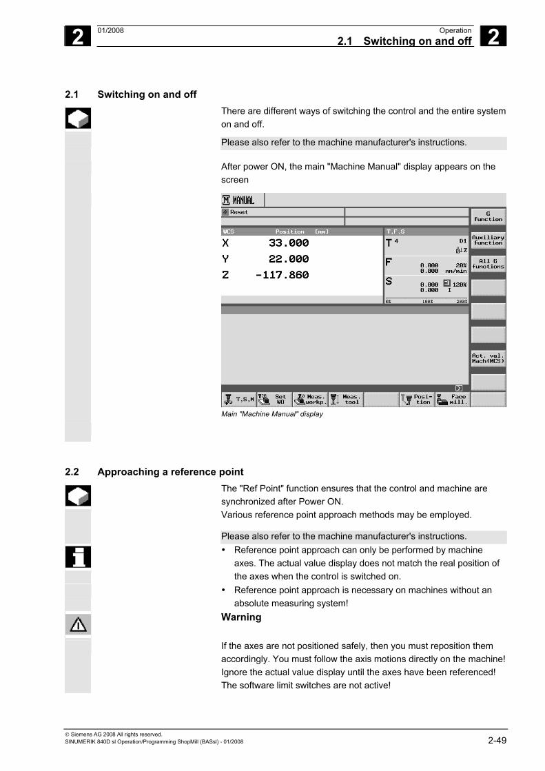
2 01/2008 Operation2.1 Switching on and off
2
© Siemens AG 2008 All rights reserved. SINUMERIK 840D sl Operation/Programming ShopMill (BASsl) - 01/2008 2-49
2.1 Switching on and off There are different ways of switching the control and the entire system
on and off.
Please also refer to the machine manufacturer's instructions.
After power ON, the main "Machine Manual" display appears on the screen
Main "Machine Manual" display
2.2 Approaching a reference point The "Ref Point" function ensures that the control and machine are
synchronized after Power ON. Various reference point approach methods may be employed.
Please also refer to the machine manufacturer's instructions. • Reference point approach can only be performed by machine
axes. The actual value display does not match the real position of the axes when the control is switched on.
• Reference point approach is necessary on machines without an absolute measuring system!
Warning
If the axes are not positioned safely, then you must reposition them accordingly. You must follow the axis motions directly on the machine!Ignore the actual value display until the axes have been referenced! The software limit switches are not active!
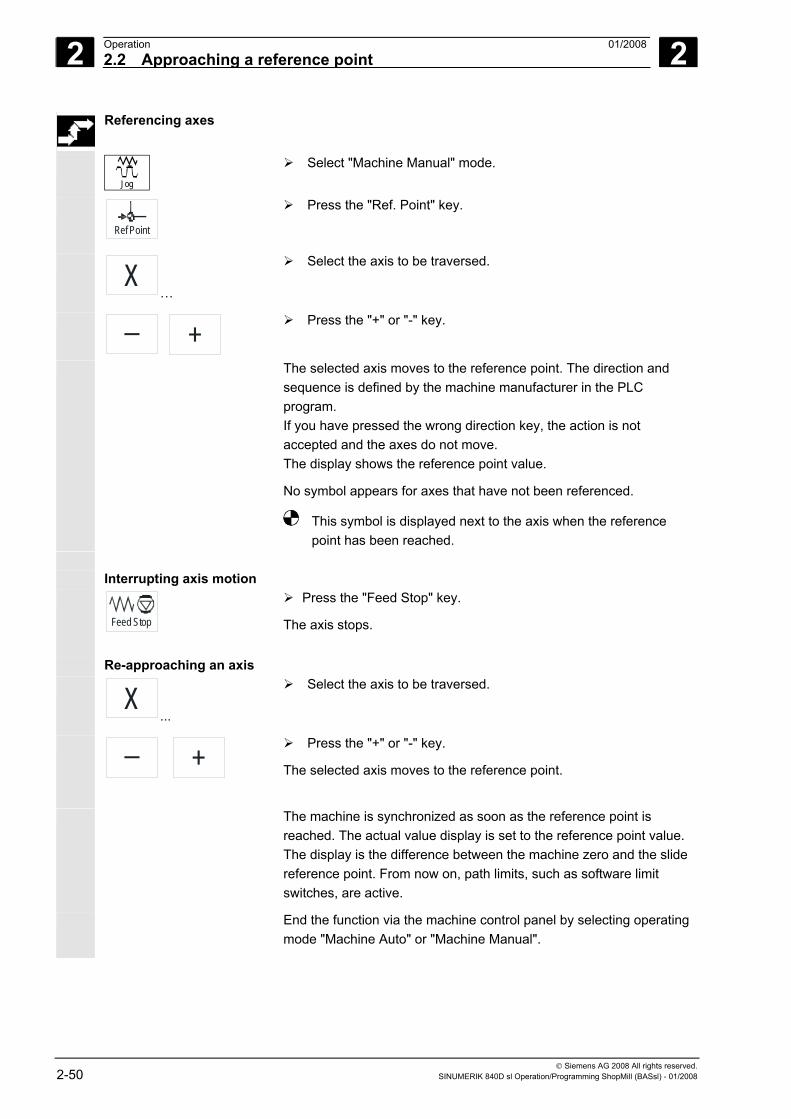
2 Operation 01/2008 2.2 Approaching a reference point
2
© Siemens AG 2008 All rights reserved. 2-50 SINUMERIK 840D sl Operation/Programming ShopMill (BASsl) - 01/2008
Referencing axes
Jog
Select "Machine Manual" mode.
Ref Point
Press the "Ref. Point" key.
X…
Select the axis to be traversed.
+
Press the "+" or "-" key.
The selected axis moves to the reference point. The direction and sequence is defined by the machine manufacturer in the PLC program. If you have pressed the wrong direction key, the action is not accepted and the axes do not move. The display shows the reference point value.
No symbol appears for axes that have not been referenced.
This symbol is displayed next to the axis when the reference point has been reached.
Interrupting axis motion
Feed Stop
Press the "Feed Stop" key.
The axis stops. Re-approaching an axis X
...
Select the axis to be traversed.
+
Press the "+" or "-" key.
The selected axis moves to the reference point.
The machine is synchronized as soon as the reference point is reached. The actual value display is set to the reference point value. The display is the difference between the machine zero and the slide reference point. From now on, path limits, such as software limit switches, are active.
End the function via the machine control panel by selecting operating mode "Machine Auto" or "Machine Manual".
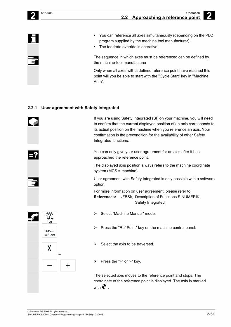
2 01/2008 Operation2.2 Approaching a reference point
2
© Siemens AG 2008 All rights reserved. SINUMERIK 840D sl Operation/Programming ShopMill (BASsl) - 01/2008 2-51
• You can reference all axes simultaneously (depending on the PLC program supplied by the machine tool manufacturer).
• The feedrate override is operative.
The sequence in which axes must be referenced can be defined by the machine-tool manufacturer.
Only when all axes with a defined reference point have reached this point will you be able to start with the "Cycle Start" key in "Machine Auto".
2.2.1 User agreement with Safety Integrated
If you are using Safety Integrated (SI) on your machine, you will need to confirm that the current displayed position of an axis corresponds to its actual position on the machine when you reference an axis. Your confirmation is the precondition for the availability of other Safety Integrated functions.
You can only give your user agreement for an axis after it has
approached the reference point.
The displayed axis position always refers to the machine coordinate system (MCS = machine).
User agreement with Safety Integrated is only possible with a software option.
For more information on user agreement, please refer to: References: /FBSI/, Description of Functions SINUMERIK Safety Integrated
Jog
Select "Machine Manual" mode.
Ref Point
Press the "Ref Point" key on the machine control panel.
X...
Select the axis to be traversed.
+
Press the "+" or "-" key.
The selected axis moves to the reference point and stops. The coordinate of the reference point is displayed. The axis is marked
with .
Jog
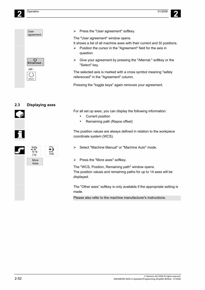
2 Operation 01/2008
2
© Siemens AG 2008 All rights reserved. 2-52 SINUMERIK 840D sl Operation/Programming ShopMill (BASsl) - 01/2008
User agreement
Press the "User agreement" softkey.
The "User agreement" window opens. It shows a list of all machine axes with their current and SI positions.
Position the cursor in the "Agreement" field for the axis in question.
-or-
Give your agreement by pressing the "Alternat." softkey or the "Select" key.
The selected axis is marked with a cross symbol meaning "safely referenced" in the "Agreement" column.
Pressing the "toggle keys" again removes your agreement.
2.3 Displaying axes For all set up axes, you can display the following information:
• Current position • Remaining path (Repos offset)
The position values are always defined in relation to the workpiece
coordinate system (WCS).
Jog Auto
Select "Machine Manual" or "Machine Auto" mode.
More Axes
Press the "More axes" softkey.
The "WCS, Position, Remaining path" window opens. The position values and remaining paths for up to 14 axes will be displayed.
The "Other axes” softkey is only available if the appropriate setting is made.
Please also refer to the machine manufacturer's instructions.
2 01/2008 Operation2.4 Operating modes
2
© Siemens AG 2008 All rights reserved. SINUMERIK 840D sl Operation/Programming ShopMill (BASsl) - 01/2008 2-53
2.4 Operating modes You can work in three different operating modes in ShopMill:
• Machine Manual • MDA (Manual Data Automatic) • Machine Auto
Machine Manual In "Machine Manual" mode, provision is made for the following
preparatory actions: • Reference point approach, i.e. calibration of the position
measuring system • Swiveling the workpiece • Preparing a machine for executing a program in automatic mode,
i.e. measuring tools, measuring the workpiece and, if necessary, defining the work offsets used in the program
• Traversing axes, e.g. during a program interruption • Positioning axes • Face milling a workpiece
Jog
You can select the "Manual Machine“ operating mode using the "Jog" key. The parameters set under "T, S, M..." affect all movements in manual mode with the exception of reference point approach.
MDA In "MDA" mode, you can enter and execute G code commands non-modally to set up the machine or to perform a single action.
MDI
You can select MDA mode via the "MDA" key.
Machine Auto In "Machine Auto" mode, you can execute a program completely or only partially. You can also trace execution of the program in a graphical display on the screen.
Auto
You can select "Machine Auto" via the "Auto" key.
2 Operation 01/2008 2.5 Settings for the machine
2
© Siemens AG 2008 All rights reserved. 2-54 SINUMERIK 840D sl Operation/Programming ShopMill (BASsl) - 01/2008
2.5 Settings for the machine
2.5.1 Switching between units of measurement (millimeters/inches)
This function enables you to switch between the metric and inch dimension systems depending on the dimension units used in your production drawing.
Every dimension system switchover applies to the entire machine, i.e. all relevant measurement data are automatically converted to the new dimension system, e.g.
• Positions • Tool offsets • Zero offsets
Jog
Open the extended horizontal softkey bar in "Machine Manual" mode.
Press the "ShopM. Settings" softkey.
Inch
Press the "Inch" softkey to switch to Inch.
The "Inch" softkey is active. Inch
Press the "Inch" softkey to switch to metric.
The "Inch" softkey is not active.
When you press the "Inch" softkey, a box appears asking you to confirm switchover.
The dimension system is adjusted accordingly if you confirm with the "OK" softkey.
2 01/2008 Operation2.5 Settings for the machine
2
© Siemens AG 2008 All rights reserved. SINUMERIK 840D sl Operation/Programming ShopMill (BASsl) - 01/2008 2-55
2.5.2 Switching the coordinate system (MCS/WCS)
The machine coordinate system (MCS) is the original system of your machine. Unlike the workpiece coordinate system (WCS), it does not allow for tool offsets, work offset, scalings, etc.
You can switch between the machine and workpiece coordinate
systems by following the sequence below.
WCS MCS
Press the "WCS MCS" key on the machine control panel
-or-
Jog Auto
Select "Machine Manual" or "Machine Auto" mode.
Actual value MCS
Press the "Actual value MCS" softkey to switch to MCS.
The "Actual value MCS" softkey is active. Actual
value MCS Press the "Actual value MCS" softkey to switch from MCS to
WCS.
The "Actual value MCS" softkey is not active.
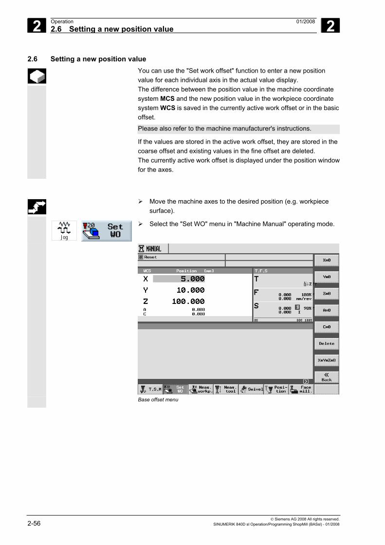
2 Operation 01/2008 2.6 Setting a new position value
2
© Siemens AG 2008 All rights reserved. 2-56 SINUMERIK 840D sl Operation/Programming ShopMill (BASsl) - 01/2008
2.6 Setting a new position value You can use the "Set work offset" function to enter a new position
value for each individual axis in the actual value display. The difference between the position value in the machine coordinate system MCS and the new position value in the workpiece coordinate system WCS is saved in the currently active work offset or in the basic offset.
Please also refer to the machine manufacturer's instructions.
If the values are stored in the active work offset, they are stored in the coarse offset and existing values in the fine offset are deleted. The currently active work offset is displayed under the position windowfor the axes.
Move the machine axes to the desired position (e.g. workpiece surface).
Jog
Select the "Set WO" menu in "Machine Manual" operating mode.
Base offset menu
2 01/2008 Operation2.6 Setting a new position value
2
© Siemens AG 2008 All rights reserved. SINUMERIK 840D sl Operation/Programming ShopMill (BASsl) - 01/2008 2-57
Setting a position value Enter the new position values with the keyboard. You can use the cursor keys to switch between positions.
Press the "Input" key to complete your entry.
-or- Press softkeys "X=0","Y=0", and "Z=0", to set the position values
to zero.
Resetting an offset
Delete
Press the "Delete" softkey.
The offset is canceled again.
The work offsets (WO1 etc.) are based on the base offset.
2 Operation 01/2008 2.7 Measuring the workpiece zero
2
© Siemens AG 2008 All rights reserved. 2-58 SINUMERIK 840D sl Operation/Programming ShopMill (BASsl) - 01/2008
2.7 Measuring the workpiece zero The reference point for programming a workpiece is always the
workpiece zero. You can determine the workpiece zero on the following workpiece elements:
• Edges, • Corner • Pocket/hole • Spigot • Plane
You can measure the workpiece zero either manually or automatically.
Manual measurement
To measure the zero point manually, you need to traverse your tool manually up to the workpiece. You can use edge probes, sensing probes, or dial gauges with known radii and lengths. You can also use any other tool of which you know the radius and length.
The tools used for measuring must not be of type 3D probe.
Automatic measurement
For automatic measurement always use electronic 3D or mono measuring probes. You must calibrate the electronic probe beforehand. In the case of automatic measuring, first position the probe manually. As soon as you start the process with the "Cycle Start" key, the probe automatically approaches the workpiece at measuring feedrate and then returns to the starting position at rapid traverse.
For automatic workpiece zero measurement, the machine manufacturer must have first set up the measuring cycles. This includes defining the measuring feedrate in the machine data.
Please also refer to the machine manufacturer's instructions.
To obtain the desired measuring results, you must keep to the measuring point sequence shown in the help displays. You can reject measuring points and then measure them again. This is done by pressing the softkey that is currently active (measured value). In manual measurement, you can reset values in any order but in automatic measurement, only in reverse order.
2 01/2008 Operation2.7 Measuring the workpiece zero
2
© Siemens AG 2008 All rights reserved. SINUMERIK 840D sl Operation/Programming ShopMill (BASsl) - 01/2008 2-59
"Measuring Only" mode If you "only" want to measure the workpiece zero, the measured values are merely displayed without changing the coordinate system.
Work offset You usually store the measured workpiece zero in a work offset. With ShopMill you can measure rotations and offsets. If necessary, you may first have to measure the rotations of your workpiece to align your workpiece and then define the zero point by measuring the offsets.
Aligning Alignment can be performed either by rotating the coordinate system or by rotating the workpiece with a rotary axis. If your machine is equipped with two rotary axes and the "swivel" function is set up, you can also align an inclined plane.
Zero point The measurement values for the offsets are stored in the coarse offset and the relevant fine offsets are deleted. If the zero point is stored in a non-active work offset, an activation window is displayed in which you can activate this work offset directly.
Rotary axes If your machine has rotary axes, you can include these rotary axes in the measurement and setup procedure. If you store the workpiece zero in a work offset, rotary axis positioning may be necessary in the following cases.
• Correcting the work offset requires you to position the rotary axes to align the workpiece parallel with the coordinate system, e.g. with "Align edge".
• Correcting the work offset rotates the workpiece coordinate system, which should align the tool perpendicular to the plane, e.g. for "Align plane".
You are supported by one or two activation windows when you position the rotary axes (see Section "Corrections after measuring the zero point").
You can only select "Rotary axis A, B, C" for the "Angle corr." parameter, if your machine has rotary axes. They must also be assigned to geometry axes in the machine data.
Please also refer to the machine manufacturer's instructions.
2 Operation 01/2008 2.7 Measuring the workpiece zero
2
© Siemens AG 2008 All rights reserved. 2-60 SINUMERIK 840D sl Operation/Programming ShopMill (BASsl) - 01/2008
Sequence of operations To measure the workpiece zero, the tool must always be perpendicular to the machining plane (e.g. with "Align plane"). In some measuring methods, the workpiece must first be aligned parallel to the coordinate system (set edge, distance 2 edges, rectangular pocket, rectangular spigot). To do this, it may be necessary to perform the measurement in several stages. 1. "Align plane" (to align the tool perpendicular to the plane) 2. "Align edge" (to align the workpiece parallel with the coordinate
system) 3. "Set edge", "Distance 2 edges", "Rectangular pocket", or
"Rectangular spigot" (to determine the zero point) or 1. "Align plane" (to align the tool perpendicular to the plane) 2. "Corner", "Holes", or "Spigots" (to align the tool parallel with the
coordinate system and define the zero point)
Pre-positioning If you want to preposition a rotary axis before measuring with "Align edge", move the rotary axis so that your workpiece is already approximately parallel to the coordinate system. Set the relevant rotary axis angle to zero with "Set WO" Measurement with "Align edge" will then correct the value for rotary axis offset or include it in the coordinate rotation and align the workpiece edge precisely.
If you want to preposition your workpiece with "Align edge" prior to measurement, you can set the angle values under "Manual swivel". With "Set zero plane" you transfer the resulting rotations into the active work offset. The measurement with "Align edge" will then correct the value for the coordinate rotations and align the workpiece precisely.
If the function "Swivel" is set up on your machine, we recommend effecting a swivel motion to zero before starting measurement. In that way, you will ensure that the rotary axis positions comply with the current coordinate system.
Examples Two typical examples are given below that demonstrate the interactionbetween and the use of "Measure workpiece" and "Manual swivel" when measuring and aligning workpieces:
2 01/2008 Operation2.7 Measuring the workpiece zero
2
© Siemens AG 2008 All rights reserved. SINUMERIK 840D sl Operation/Programming ShopMill (BASsl) - 01/2008 2-61
Example 1: Remachining on a cylinder head with 2 holes on an inclined plane.
1. Clamp the workpiece
2. Insert T, S, M probes and activate the required work offset.
3. Preposition workpiece rotate rotary axes manually until the inclined surface is almost perpendicular to the tool axis.
4. Manual swiveling Select "direct" swiveling, "Teach rotary axes", and press "Cycle start".
5. Manual swiveling Apply "Set zero plane" to store the resulting rotations in the work zero.
6. Measure workpiece Apply "Align plane" to correct the alignment of the workpiece.
7. Measure workpiece Apply "2 holes" to define the rotation and offset in the XY plane.
8. Measure workpiece Apply "Set edge Z" to define the offset in Z.
9. Start part program to remachine in AUTO. Start the program with swivel zero.
Example 2:
Measuring workpieces in swiveled position. The workpiece is to be probed in the X direction even though the probe cannot approach the workpiece in the X direction because of an obstructing edge. But with a swivel movement, the measurement in the X direction can be replaced by a measurement in the Z direction.
1. Clamp the workpiece
2. Insert T, S, M probes and activate the required work offset.
2 Operation 01/2008 2.7 Measuring the workpiece zero
2
© Siemens AG 2008 All rights reserved. 2-62 SINUMERIK 840D sl Operation/Programming ShopMill (BASsl) - 01/2008
3. Swivel manually With "direct" swiveling enter the required rotary axis positions or with "axis by axis" the required rotations (e.g. Y=-90) and "cycle start".
4. Measure the workpiece Apply "Apply edge Z": The measured offset in Z is converted and entered as an X value in the chosen work offset.
5. Swivel manually Execute swivel to zero in order to rotate the coordinate system to its initial position.
2.7.1 Measuring an edge
The following options are available to you when measuring an edge:
• Set the edge The workpiece lies parallel to the coordinate system on the work table. You measure one reference point in one of the axes (X, Y, Z).
• Align the edge The workpiece lies in any direction, i.e. not parallel to the coordinate system on the work table. By measuring two points on the workpiece edge you determine the angle with the coordinate system.
• Distance 2 edges The workpiece lies parallel to the coordinate system on the work table. You measure distance L of two parallel workpiece edges in one of the axes (X, Y, or Z) and determine its center.
2 01/2008 Operation2.7 Measuring the workpiece zero
2
© Siemens AG 2008 All rights reserved. SINUMERIK 840D sl Operation/Programming ShopMill (BASsl) - 01/2008 2-63
Setting an edge manually
1. Attach any tool for scratching to the spindle.
Jog
2. In "Machine Manual" mode, select the "Meas. workp." softkey.
3. Press the "Edge" softkey. The "Edge" window opens with new vertical softkeys.
4. Press the "Set edge" softkey.
5. Select "Measurement only", if you only want to display the measured values.
- OR - Select "Work offset" and the work zero in which you want to store
the zero point (e.g. base reference).
- OR - Work
offset Press the "Work offset" softkey.
The "work offset list" is displayed.
Place the cursor on the chosen work offset (e.g. base reference).
In manual
Press the "In manual" softkey.
X
Z
6. Use the softkeys to select in which axis direction you want to approach the workpiece first.
7. Select the measuring direction (+ or -) you want to approach the workpiece in.
8. Specify the setpoint position of the workpiece edge you are approaching. The setpoint position corresponds, e.g. to the dimension specifications of the workpiece edge from the workpiece drawing.
9. Traverse the tool to the workpiece edge. Set WO
-or- Calculate
10. Press the "Set WO" or "Calculate" softkey.
The position of the workpiece edge is calculated and displayed. The set position of the workpiece edge is stored as the new zero point when "Set WO" is pressed. The tool radius is automatically included in the calculation.
Example: Reference point workpiece edge X0 = -50 Approach direction: + Tool radius = 3 mm ⇒ Work offset X = 53
11. Repeat the measurement procedure (steps 6 to 10) for the two other axes, if necessary.
2 Operation 01/2008 2.7 Measuring the workpiece zero
2
© Siemens AG 2008 All rights reserved. 2-64 SINUMERIK 840D sl Operation/Programming ShopMill (BASsl) - 01/2008
Setting an edge automatically
1. Attach a 3D probe type tool to the spindle.
2. Prepare the measurement (as described under "Setting the edge manually", steps 2 to 8).
3. Move the tool up close to the workpiece edge you want to measure.
Cycle Start
4. Press the "Cycle Start" key.
This starts the automatic measuring process. The position of the workpiece edge is measured.
The position of the workpiece edge is calculated and displayed. The set position of the workpiece edge is stored as the new zero point if you have selected "work offset". The tool radius is automatically included in the calculation.
5. Repeat the measurement procedure (steps 3 to 4) for the two other axes, if applicable.
Aligning an edge
manually
1. Attach any tool for scratching to the spindle.
Jog
2. In "Machine Manual" mode, select the "Meas. workp." softkey.
3. Press the "Edge" softkey. The "Edge" window opens with new vertical softkeys.
4. Press the "Align edge" softkey.
5. Specify whether you want "Measurement only" or in which work offset you want to store the zero point (as described under "Setting the edge manually", step 5).
6. Under "Measuring axis", select the axis in which you want to approach the workpiece.
7. Under "Reference axis", select the axis to which the angle to be measured refers.
8. Under "Angle offs." select entry "Coor. Rotation”.
- OR - Under "Angle offs.", select the "Rotary axis A, B, C" entry.
9. Enter the setpoint angle between the workpiece edge and the reference axis.
10. Traverse the tool to the workpiece edge. Save P1
11. Press the "Save P1" softkey.
Save P2
12. Reposition the tool and repeat the measuring procedure (steps 6 to 11) to measure the second point, and then press the "Save P2" softkey.
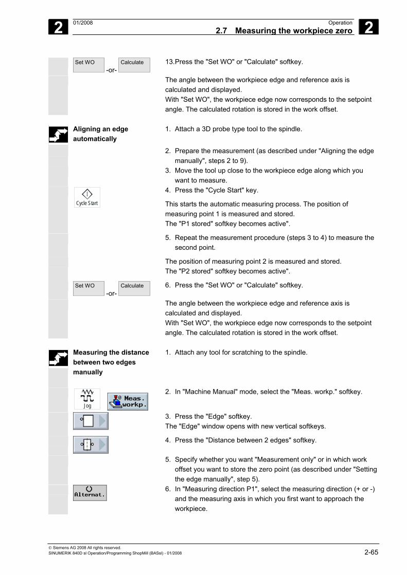
2 01/2008 Operation2.7 Measuring the workpiece zero
2
© Siemens AG 2008 All rights reserved. SINUMERIK 840D sl Operation/Programming ShopMill (BASsl) - 01/2008 2-65
Set WO -or-
Calculate
13. Press the "Set WO" or "Calculate" softkey.
The angle between the workpiece edge and reference axis is calculated and displayed. With "Set WO", the workpiece edge now corresponds to the setpoint angle. The calculated rotation is stored in the work offset.
Aligning an edge
automatically 1. Attach a 3D probe type tool to the spindle.
2. Prepare the measurement (as described under "Aligning the edge manually", steps 2 to 9).
3. Move the tool up close to the workpiece edge along which you want to measure.
Cycle Start
4. Press the "Cycle Start" key.
This starts the automatic measuring process. The position of measuring point 1 is measured and stored. The "P1 stored" softkey becomes active".
5. Repeat the measurement procedure (steps 3 to 4) to measure the second point.
The position of measuring point 2 is measured and stored. The "P2 stored" softkey becomes active".
Set WO -or-
Calculate
6. Press the "Set WO" or "Calculate" softkey.
The angle between the workpiece edge and reference axis is calculated and displayed. With "Set WO", the workpiece edge now corresponds to the setpoint angle. The calculated rotation is stored in the work offset.
Measuring the distance
between two edges manually
1. Attach any tool for scratching to the spindle.
Jog
2. In "Machine Manual" mode, select the "Meas. workp." softkey.
3. Press the "Edge" softkey. The "Edge" window opens with new vertical softkeys.
4. Press the "Distance between 2 edges" softkey.
5. Specify whether you want "Measurement only" or in which work offset you want to store the zero point (as described under "Setting the edge manually", step 5).
6. In "Measuring direction P1", select the measuring direction (+ or -) and the measuring axis in which you first want to approach the workpiece.
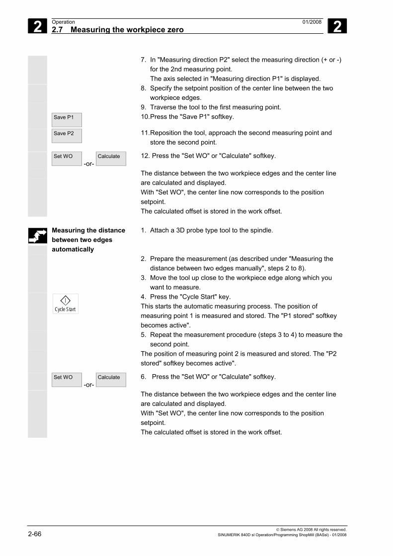
2 Operation 01/2008 2.7 Measuring the workpiece zero
2
© Siemens AG 2008 All rights reserved. 2-66 SINUMERIK 840D sl Operation/Programming ShopMill (BASsl) - 01/2008
7. In "Measuring direction P2" select the measuring direction (+ or -) for the 2nd measuring point. The axis selected in "Measuring direction P1" is displayed.
8. Specify the setpoint position of the center line between the two workpiece edges.
9. Traverse the tool to the first measuring point. Save P1
10. Press the "Save P1" softkey.
Save P2
11. Reposition the tool, approach the second measuring point and store the second point.
Set WO -or-
Calculate
12. Press the "Set WO" or "Calculate" softkey.
The distance between the two workpiece edges and the center line are calculated and displayed. With "Set WO", the center line now corresponds to the position setpoint. The calculated offset is stored in the work offset.
Measuring the distance
between two edges automatically
1. Attach a 3D probe type tool to the spindle.
2. Prepare the measurement (as described under "Measuring the distance between two edges manually", steps 2 to 8).
3. Move the tool up close to the workpiece edge along which you want to measure.
Cycle Start
4. Press the "Cycle Start" key. This starts the automatic measuring process. The position of measuring point 1 is measured and stored. The "P1 stored" softkey becomes active".
5. Repeat the measurement procedure (steps 3 to 4) to measure the second point.
The position of measuring point 2 is measured and stored. The "P2 stored" softkey becomes active".
Set WO -or-
Calculate
6. Press the "Set WO" or "Calculate" softkey.
The distance between the two workpiece edges and the center line are calculated and displayed. With "Set WO", the center line now corresponds to the position setpoint. The calculated offset is stored in the work offset.
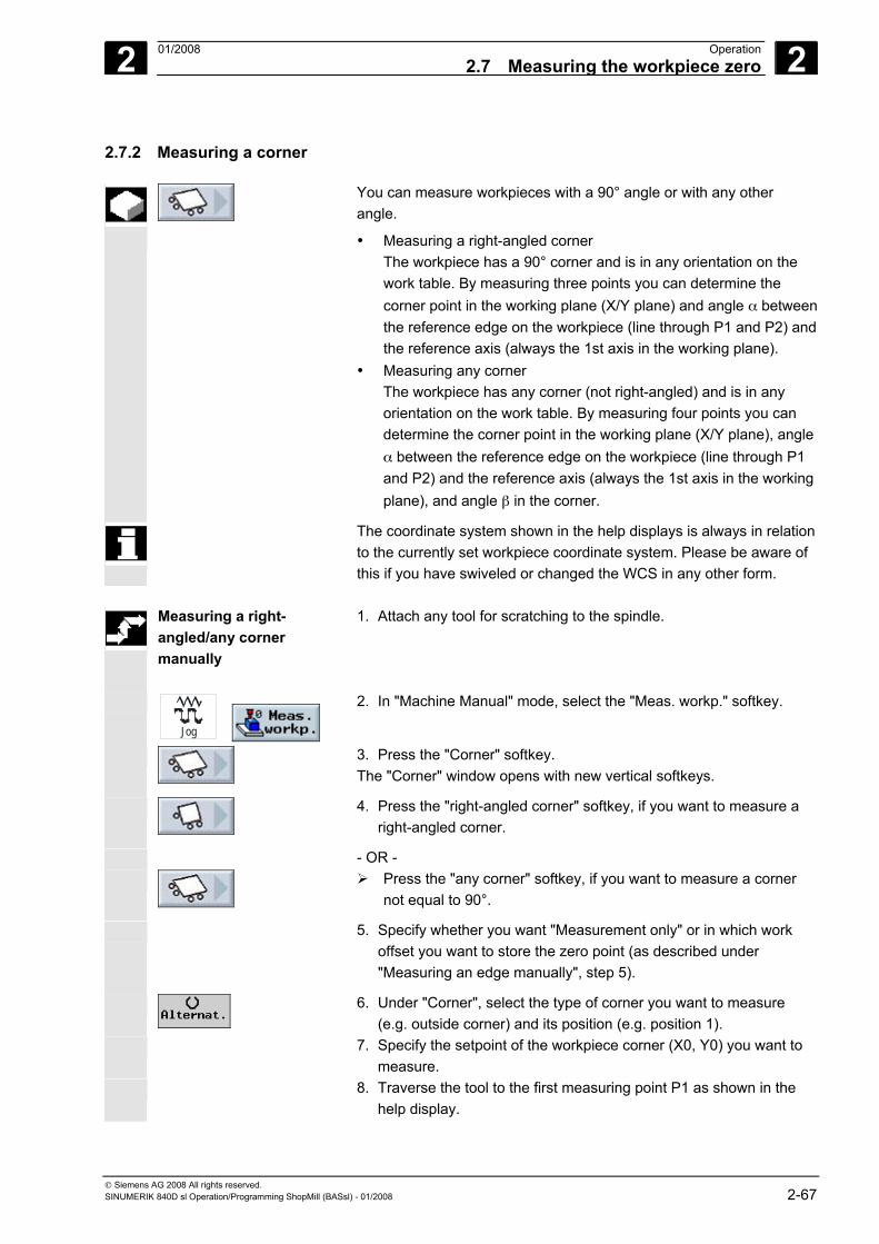
2 01/2008 Operation2.7 Measuring the workpiece zero
2
© Siemens AG 2008 All rights reserved. SINUMERIK 840D sl Operation/Programming ShopMill (BASsl) - 01/2008 2-67
2.7.2 Measuring a corner
You can measure workpieces with a 90° angle or with any other angle.
• Measuring a right-angled corner The workpiece has a 90° corner and is in any orientation on the work table. By measuring three points you can determine the corner point in the working plane (X/Y plane) and angle α between the reference edge on the workpiece (line through P1 and P2) and the reference axis (always the 1st axis in the working plane).
• Measuring any corner The workpiece has any corner (not right-angled) and is in any orientation on the work table. By measuring four points you can determine the corner point in the working plane (X/Y plane), angle α between the reference edge on the workpiece (line through P1 and P2) and the reference axis (always the 1st axis in the working plane), and angle β in the corner.
The coordinate system shown in the help displays is always in relation to the currently set workpiece coordinate system. Please be aware of this if you have swiveled or changed the WCS in any other form.
Measuring a right-
angled/any corner manually
1. Attach any tool for scratching to the spindle.
Jog
2. In "Machine Manual" mode, select the "Meas. workp." softkey.
3. Press the "Corner" softkey. The "Corner" window opens with new vertical softkeys.
4. Press the "right-angled corner" softkey, if you want to measure a right-angled corner.
- OR -
Press the "any corner" softkey, if you want to measure a corner
not equal to 90°. 5. Specify whether you want "Measurement only" or in which work
offset you want to store the zero point (as described under "Measuring an edge manually", step 5).
6. Under "Corner", select the type of corner you want to measure (e.g. outside corner) and its position (e.g. position 1).
7. Specify the setpoint of the workpiece corner (X0, Y0) you want to measure.
8. Traverse the tool to the first measuring point P1 as shown in the help display.
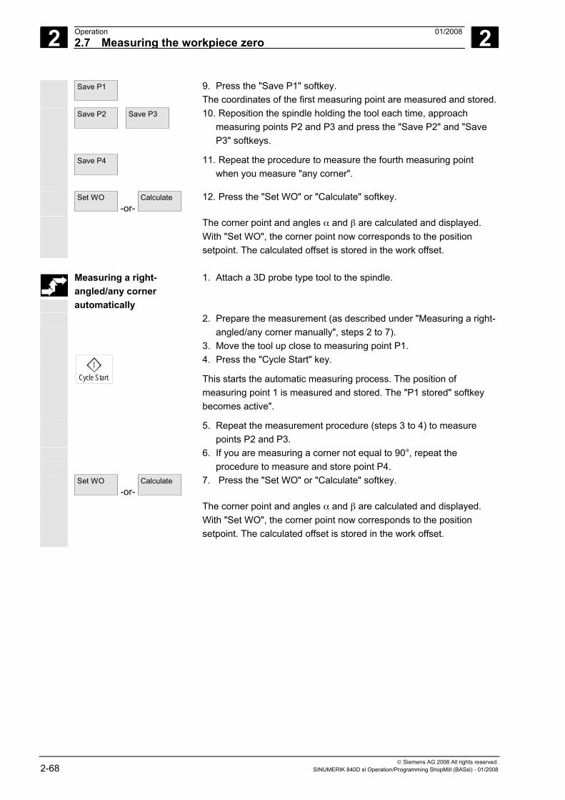
2 Operation 01/2008 2.7 Measuring the workpiece zero
2
© Siemens AG 2008 All rights reserved. 2-68 SINUMERIK 840D sl Operation/Programming ShopMill (BASsl) - 01/2008
Save P1
9. Press the "Save P1" softkey. The coordinates of the first measuring point are measured and stored.
Save P2
Save P3
10. Reposition the spindle holding the tool each time, approach measuring points P2 and P3 and press the "Save P2" and "Save P3" softkeys.
Save P4
11. Repeat the procedure to measure the fourth measuring point when you measure "any corner".
Set WO -or-
Calculate
12. Press the "Set WO" or "Calculate" softkey.
The corner point and angles α and β are calculated and displayed. With "Set WO", the corner point now corresponds to the position setpoint. The calculated offset is stored in the work offset.
Measuring a right-
angled/any corner automatically
1. Attach a 3D probe type tool to the spindle.
2. Prepare the measurement (as described under "Measuring a right-angled/any corner manually", steps 2 to 7).
3. Move the tool up close to measuring point P1.
Cycle Start
4. Press the "Cycle Start" key.
This starts the automatic measuring process. The position of measuring point 1 is measured and stored. The "P1 stored" softkey becomes active".
5. Repeat the measurement procedure (steps 3 to 4) to measure points P2 and P3.
6. If you are measuring a corner not equal to 90°, repeat the procedure to measure and store point P4.
Set WO -or-
Calculate
7. Press the "Set WO" or "Calculate" softkey.
The corner point and angles α and β are calculated and displayed. With "Set WO", the corner point now corresponds to the position setpoint. The calculated offset is stored in the work offset.
2 01/2008 Operation2.7 Measuring the workpiece zero
2
© Siemens AG 2008 All rights reserved. SINUMERIK 840D sl Operation/Programming ShopMill (BASsl) - 01/2008 2-69
2.7.3 Measuring pockets and holes
You can measure rectangular pockets and one or more holes and then align the workpiece.
• Measuring a rectangular pocket The rectangular pocket must be aligned at right-angles to the coordinate system. By measuring four points inside the pocket you can determine the length, width, and center point of the pocket.
• Measuring 1 hole The workpiece is in any orientation on the work table and has one hole. You can determine the diameter and center point of the hole with four measuring points.
• Measuring 2 holes The workpiece is in any orientation on the work table and has two holes. 4 points are automatically measured in both holes and the hole centers are calculated from them. Angle α is calculated from the connecting line between both center points and the reference axis, and the new zero point that corresponds to the center point of the 1st hole is determined.
• Measuring 3 holes The workpiece is in any orientation on the work table and has three holes. 4 points are automatically measured in the three holes and the hole centers are calculated from them. A circle is placed through the three center points. The circle center point and diameter are determined from it. If an angle offset is selected, base angle of rotation α can also be found.
• Measuring 4 holes The workpiece is in any orientation on the work table and has four holes. 4 points are automatically measured in the four holes and the hole centers are calculated from them. Two hole center points are diagonally connected in each case. The point of intersection between the two lines is determined from this. If an angle offset is selected, base angle of rotation α can also be found.
You can only measure 2, 3, and 4 holes automatically.
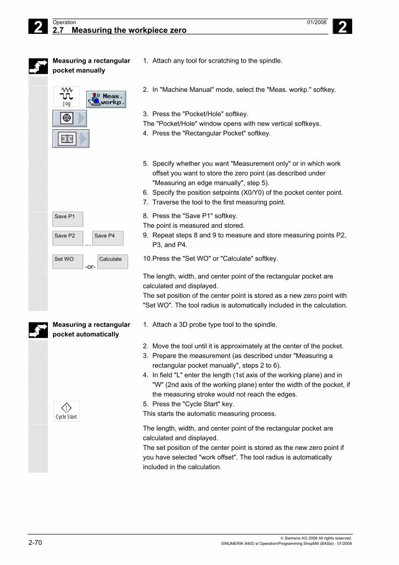
2 Operation 01/2008 2.7 Measuring the workpiece zero
2
© Siemens AG 2008 All rights reserved. 2-70 SINUMERIK 840D sl Operation/Programming ShopMill (BASsl) - 01/2008
Measuring a rectangular pocket manually
1. Attach any tool for scratching to the spindle.
Jog
2. In "Machine Manual" mode, select the "Meas. workp." softkey.
3. Press the "Pocket/Hole" softkey. The "Pocket/Hole" window opens with new vertical softkeys.
4. Press the "Rectangular Pocket" softkey.
5. Specify whether you want "Measurement only" or in which work offset you want to store the zero point (as described under "Measuring an edge manually", step 5).
6. Specify the position setpoints (X0/Y0) of the pocket center point. 7. Traverse the tool to the first measuring point.
Save P1
8. Press the "Save P1" softkey. The point is measured and stored.
Save P2 ...
Save P4
9. Repeat steps 8 and 9 to measure and store measuring points P2, P3, and P4.
Set WO -or-
Calculate
10. Press the "Set WO" or "Calculate" softkey.
The length, width, and center point of the rectangular pocket are calculated and displayed. The set position of the center point is stored as a new zero point with "Set WO". The tool radius is automatically included in the calculation.
Measuring a rectangular
pocket automatically 1. Attach a 3D probe type tool to the spindle.
2. Move the tool until it is approximately at the center of the pocket. 3. Prepare the measurement (as described under "Measuring a
rectangular pocket manually", steps 2 to 6). 4. In field "L" enter the length (1st axis of the working plane) and in
"W" (2nd axis of the working plane) enter the width of the pocket, if the measuring stroke would not reach the edges.
Cycle Start
5. Press the "Cycle Start" key. This starts the automatic measuring process.
The length, width, and center point of the rectangular pocket are calculated and displayed. The set position of the center point is stored as the new zero point if you have selected "work offset". The tool radius is automatically included in the calculation.
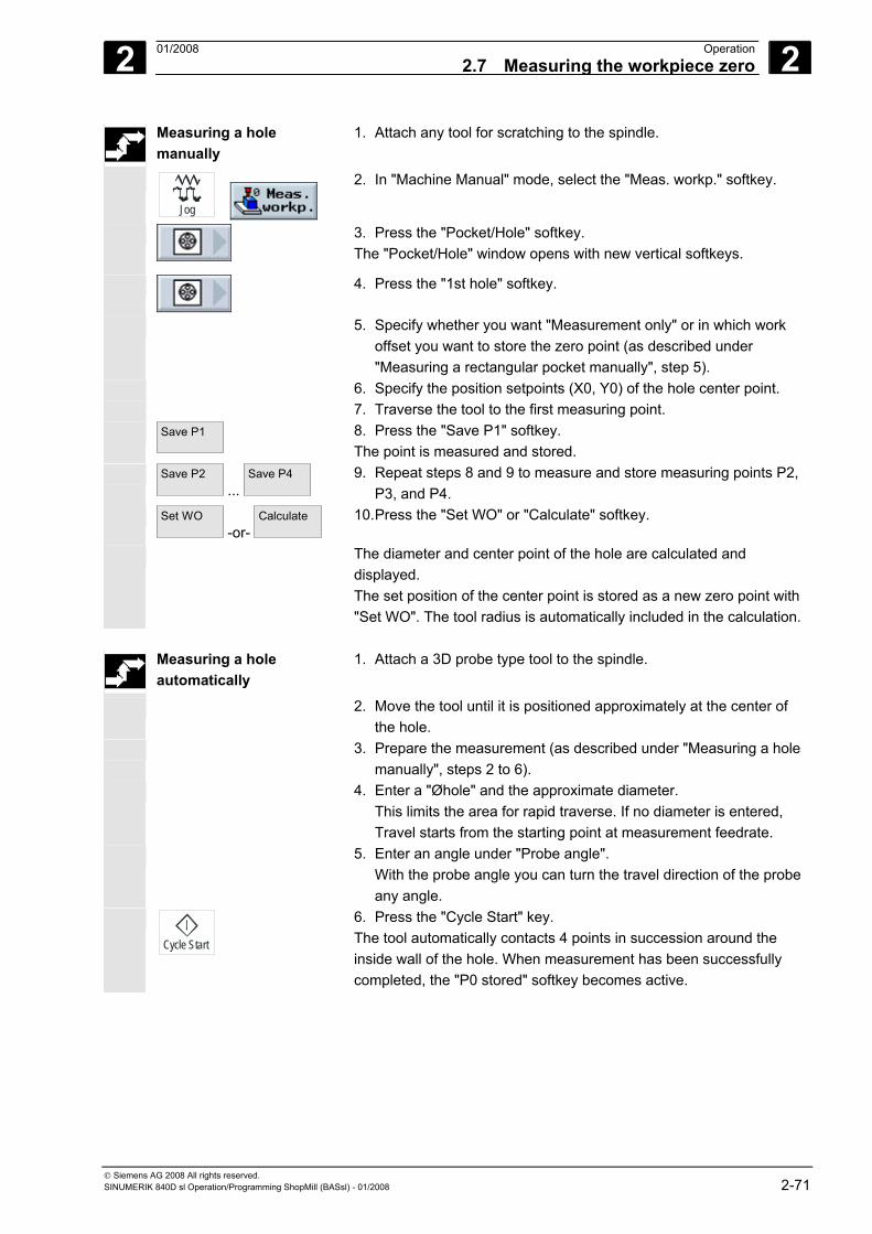
2 01/2008 Operation2.7 Measuring the workpiece zero
2
© Siemens AG 2008 All rights reserved. SINUMERIK 840D sl Operation/Programming ShopMill (BASsl) - 01/2008 2-71
Measuring a hole manually
1. Attach any tool for scratching to the spindle.
Jog
2. In "Machine Manual" mode, select the "Meas. workp." softkey.
3. Press the "Pocket/Hole" softkey. The "Pocket/Hole" window opens with new vertical softkeys.
4. Press the "1st hole" softkey.
5. Specify whether you want "Measurement only" or in which work offset you want to store the zero point (as described under "Measuring a rectangular pocket manually", step 5).
6. Specify the position setpoints (X0, Y0) of the hole center point. 7. Traverse the tool to the first measuring point. Save P1
8. Press the "Save P1" softkey. The point is measured and stored.
Save P2 ...
Save P4
9. Repeat steps 8 and 9 to measure and store measuring points P2, P3, and P4.
Set WO -or-
Calculate
10. Press the "Set WO" or "Calculate" softkey.
The diameter and center point of the hole are calculated and displayed. The set position of the center point is stored as a new zero point with "Set WO". The tool radius is automatically included in the calculation.
Measuring a hole
automatically 1. Attach a 3D probe type tool to the spindle.
2. Move the tool until it is positioned approximately at the center of the hole.
3. Prepare the measurement (as described under "Measuring a hole manually", steps 2 to 6).
4. Enter a "Øhole" and the approximate diameter. This limits the area for rapid traverse. If no diameter is entered, Travel starts from the starting point at measurement feedrate.
5. Enter an angle under "Probe angle". With the probe angle you can turn the travel direction of the probe any angle.
Cycle Start
6. Press the "Cycle Start" key. The tool automatically contacts 4 points in succession around the inside wall of the hole. When measurement has been successfully completed, the "P0 stored" softkey becomes active.
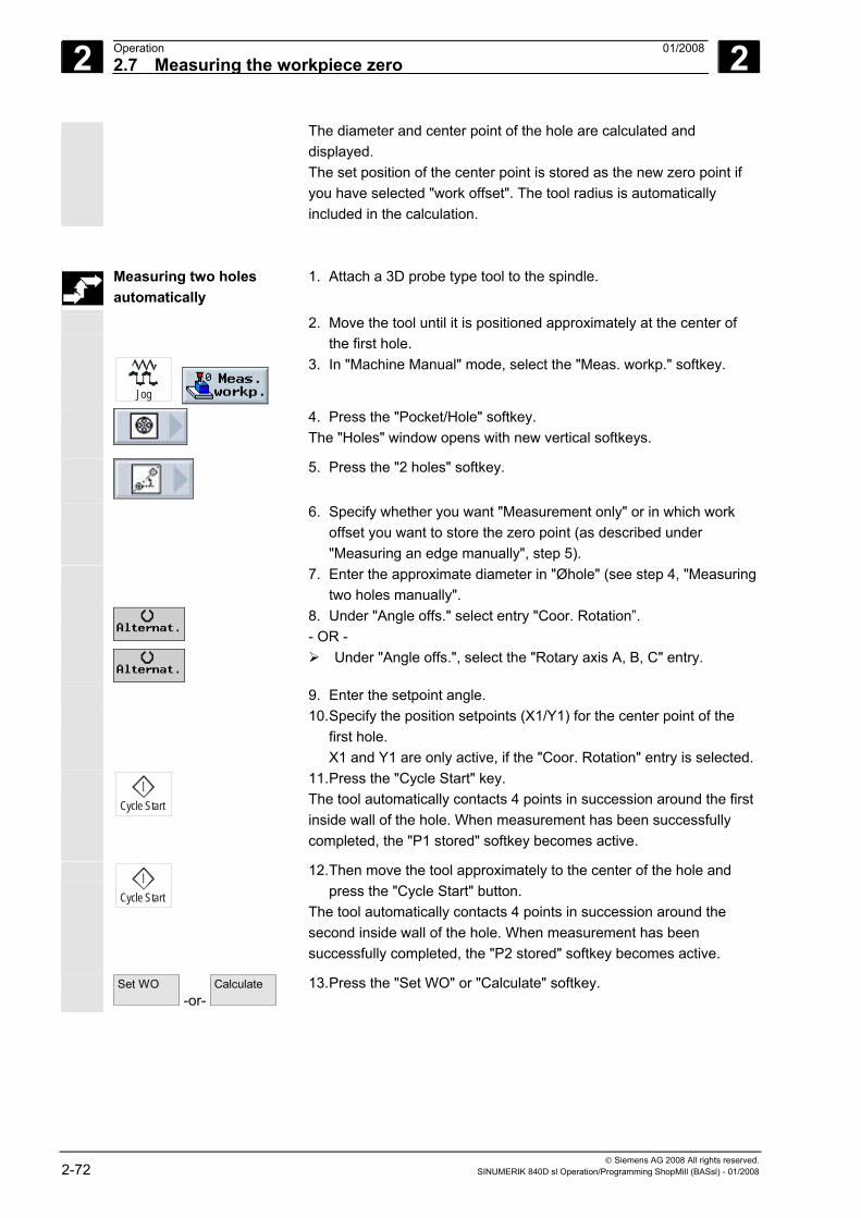
2 Operation 01/2008 2.7 Measuring the workpiece zero
2
© Siemens AG 2008 All rights reserved. 2-72 SINUMERIK 840D sl Operation/Programming ShopMill (BASsl) - 01/2008
The diameter and center point of the hole are calculated and displayed. The set position of the center point is stored as the new zero point if you have selected "work offset". The tool radius is automatically included in the calculation.
Measuring two holes automatically
1. Attach a 3D probe type tool to the spindle.
2. Move the tool until it is positioned approximately at the center of the first hole.
Jog
3. In "Machine Manual" mode, select the "Meas. workp." softkey.
4. Press the "Pocket/Hole" softkey. The "Holes" window opens with new vertical softkeys.
5. Press the "2 holes" softkey.
6. Specify whether you want "Measurement only" or in which work offset you want to store the zero point (as described under "Measuring an edge manually", step 5).
7. Enter the approximate diameter in "Øhole" (see step 4, "Measuring two holes manually".
8. Under "Angle offs." select entry "Coor. Rotation”. - OR -
Under "Angle offs.", select the "Rotary axis A, B, C" entry.
9. Enter the setpoint angle. 10. Specify the position setpoints (X1/Y1) for the center point of the
first hole. X1 and Y1 are only active, if the "Coor. Rotation" entry is selected.
Cycle Start
11. Press the "Cycle Start" key. The tool automatically contacts 4 points in succession around the first inside wall of the hole. When measurement has been successfully completed, the "P1 stored" softkey becomes active.
Cycle Start
12. Then move the tool approximately to the center of the hole and press the "Cycle Start" button.
The tool automatically contacts 4 points in succession around the second inside wall of the hole. When measurement has been successfully completed, the "P2 stored" softkey becomes active.
Set WO -or-
Calculate
13. Press the "Set WO" or "Calculate" softkey.
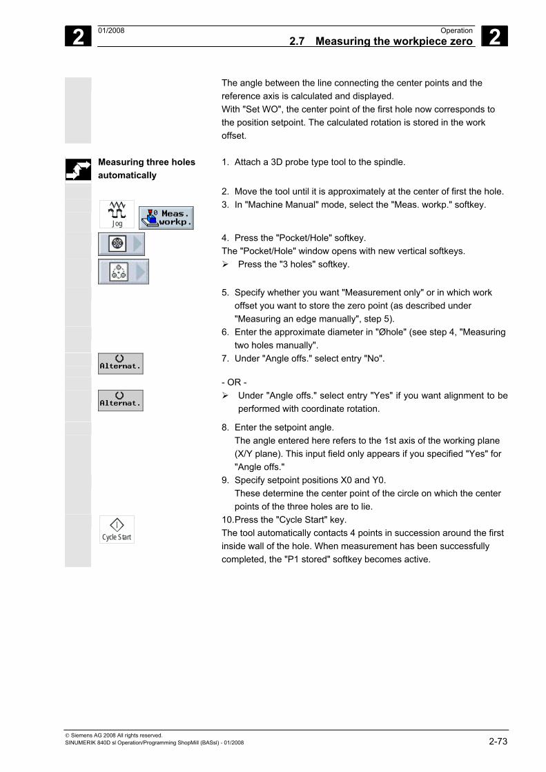
2 01/2008 Operation2.7 Measuring the workpiece zero
2
© Siemens AG 2008 All rights reserved. SINUMERIK 840D sl Operation/Programming ShopMill (BASsl) - 01/2008 2-73
The angle between the line connecting the center points and the reference axis is calculated and displayed. With "Set WO", the center point of the first hole now corresponds to the position setpoint. The calculated rotation is stored in the work offset.
Measuring three holes
automatically 1. Attach a 3D probe type tool to the spindle.
2. Move the tool until it is approximately at the center of first the hole.
Jog
3. In "Machine Manual" mode, select the "Meas. workp." softkey.
4. Press the "Pocket/Hole" softkey. The "Pocket/Hole" window opens with new vertical softkeys.
Press the "3 holes" softkey.
5. Specify whether you want "Measurement only" or in which work offset you want to store the zero point (as described under "Measuring an edge manually", step 5).
6. Enter the approximate diameter in "Øhole" (see step 4, "Measuring two holes manually".
7. Under "Angle offs." select entry "No".
- OR -
Under "Angle offs." select entry "Yes" if you want alignment to be
performed with coordinate rotation.
8. Enter the setpoint angle. The angle entered here refers to the 1st axis of the working plane (X/Y plane). This input field only appears if you specified "Yes" for "Angle offs."
9. Specify setpoint positions X0 and Y0. These determine the center point of the circle on which the center points of the three holes are to lie.
Cycle Start
10. Press the "Cycle Start" key. The tool automatically contacts 4 points in succession around the first inside wall of the hole. When measurement has been successfully completed, the "P1 stored" softkey becomes active.
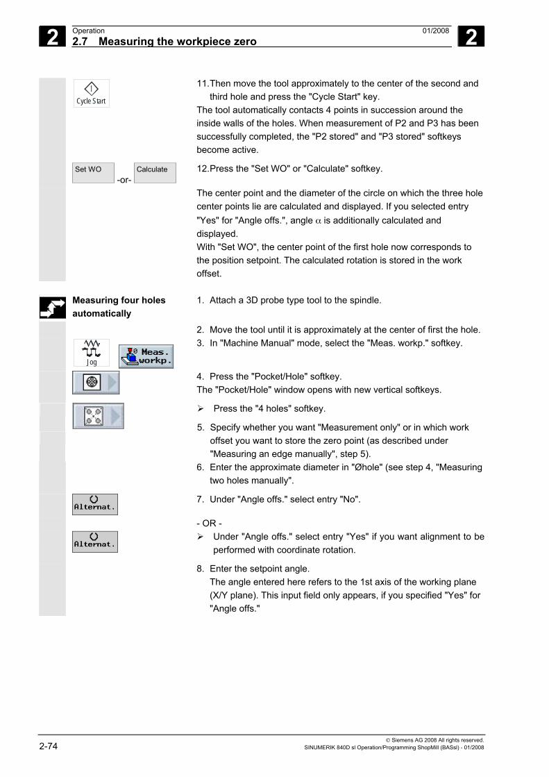
2 Operation 01/2008 2.7 Measuring the workpiece zero
2
© Siemens AG 2008 All rights reserved. 2-74 SINUMERIK 840D sl Operation/Programming ShopMill (BASsl) - 01/2008
Cycle Start
11. Then move the tool approximately to the center of the second and third hole and press the "Cycle Start" key.
The tool automatically contacts 4 points in succession around the inside walls of the holes. When measurement of P2 and P3 has been successfully completed, the "P2 stored" and "P3 stored" softkeys become active.
Set WO -or-
Calculate
12. Press the "Set WO" or "Calculate" softkey.
The center point and the diameter of the circle on which the three hole center points lie are calculated and displayed. If you selected entry "Yes" for "Angle offs.", angle α is additionally calculated and displayed. With "Set WO", the center point of the first hole now corresponds to the position setpoint. The calculated rotation is stored in the work offset.
Measuring four holes
automatically 1. Attach a 3D probe type tool to the spindle.
2. Move the tool until it is approximately at the center of first the hole.
Jog
3. In "Machine Manual" mode, select the "Meas. workp." softkey.
4. Press the "Pocket/Hole" softkey. The "Pocket/Hole" window opens with new vertical softkeys.
Press the "4 holes" softkey.
5. Specify whether you want "Measurement only" or in which work offset you want to store the zero point (as described under "Measuring an edge manually", step 5).
6. Enter the approximate diameter in "Øhole" (see step 4, "Measuring two holes manually".
7. Under "Angle offs." select entry "No".
- OR -
Under "Angle offs." select entry "Yes" if you want alignment to be
performed with coordinate rotation.
8. Enter the setpoint angle. The angle entered here refers to the 1st axis of the working plane (X/Y plane). This input field only appears, if you specified "Yes" for "Angle offs."
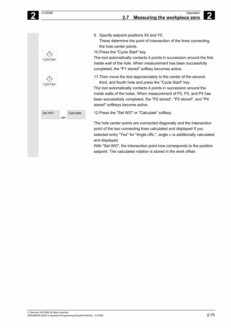
2 01/2008 Operation2.7 Measuring the workpiece zero
2
© Siemens AG 2008 All rights reserved. SINUMERIK 840D sl Operation/Programming ShopMill (BASsl) - 01/2008 2-75
9. Specify setpoint positions X0 and Y0. These determine the point of intersection of the lines connecting the hole center points.
Cycle Start
10. Press the "Cycle Start" key. The tool automatically contacts 4 points in succession around the first inside wall of the hole. When measurement has been successfully completed, the "P1 stored" softkey becomes active.
Cycle Start
11. Then move the tool approximately to the center of the second, third, and fourth hole and press the "Cycle Start" key.
The tool automatically contacts 4 points in succession around the inside walls of the holes. When measurement of P2, P3, and P4 has been successfully completed, the "P2 stored", "P3 stored", and "P4 stored" softkeys become active.
Set WO -or-
Calculate
12. Press the "Set WO" or "Calculate" softkey.
The hole center points are connected diagonally and the intersection point of the two connecting lines calculated and displayed If you selected entry "Yes" for "Angle offs.", angle α is additionally calculated and displayed. With "Set WO", the intersection point now corresponds to the position setpoint. The calculated rotation is stored in the work offset.
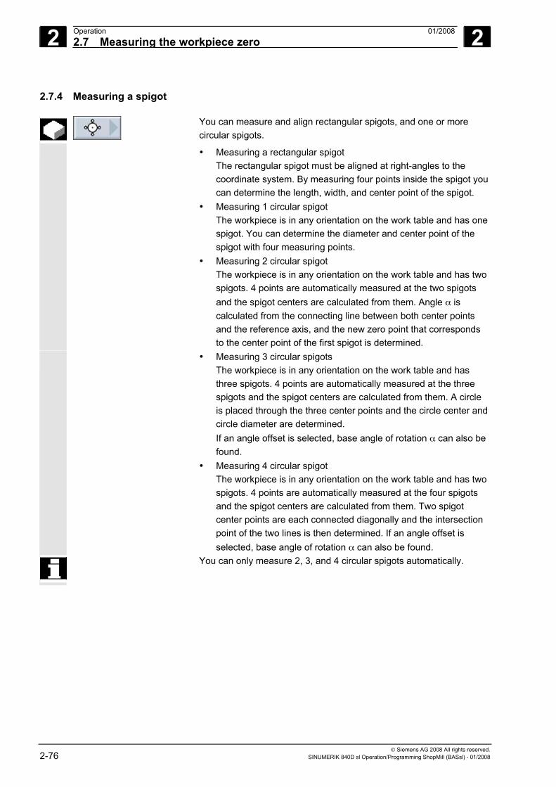
2 Operation 01/2008 2.7 Measuring the workpiece zero
2
© Siemens AG 2008 All rights reserved. 2-76 SINUMERIK 840D sl Operation/Programming ShopMill (BASsl) - 01/2008
2.7.4 Measuring a spigot
You can measure and align rectangular spigots, and one or more circular spigots.
• Measuring a rectangular spigot The rectangular spigot must be aligned at right-angles to the coordinate system. By measuring four points inside the spigot you can determine the length, width, and center point of the spigot.
• Measuring 1 circular spigot The workpiece is in any orientation on the work table and has one spigot. You can determine the diameter and center point of the spigot with four measuring points.
• Measuring 2 circular spigot The workpiece is in any orientation on the work table and has two spigots. 4 points are automatically measured at the two spigots and the spigot centers are calculated from them. Angle α is calculated from the connecting line between both center points and the reference axis, and the new zero point that corresponds to the center point of the first spigot is determined.
• Measuring 3 circular spigots The workpiece is in any orientation on the work table and has three spigots. 4 points are automatically measured at the three spigots and the spigot centers are calculated from them. A circle is placed through the three center points and the circle center and circle diameter are determined. If an angle offset is selected, base angle of rotation α can also be found.
• Measuring 4 circular spigot The workpiece is in any orientation on the work table and has two spigots. 4 points are automatically measured at the four spigots and the spigot centers are calculated from them. Two spigot center points are each connected diagonally and the intersection point of the two lines is then determined. If an angle offset is selected, base angle of rotation α can also be found.
You can only measure 2, 3, and 4 circular spigots automatically.
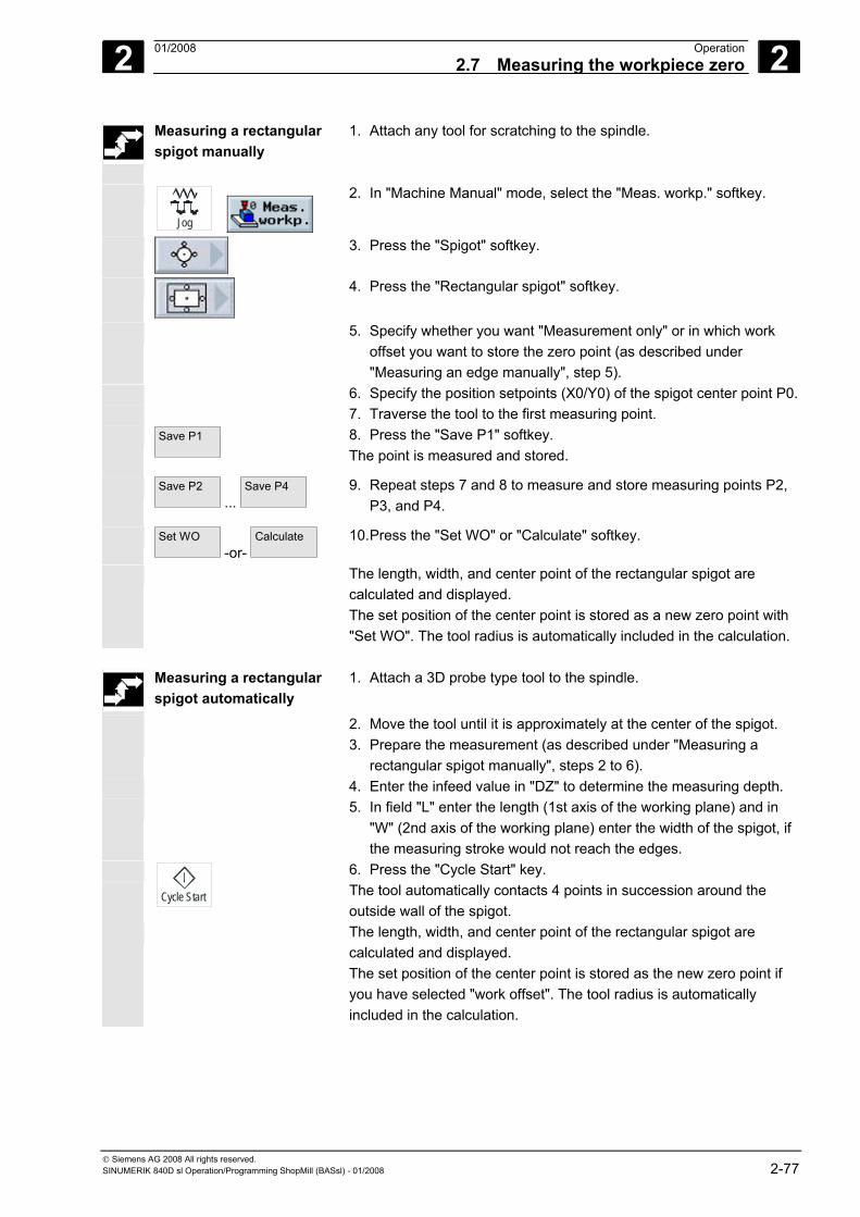
2 01/2008 Operation2.7 Measuring the workpiece zero
2
© Siemens AG 2008 All rights reserved. SINUMERIK 840D sl Operation/Programming ShopMill (BASsl) - 01/2008 2-77
Measuring a rectangular spigot manually
1. Attach any tool for scratching to the spindle.
Jog
2. In "Machine Manual" mode, select the "Meas. workp." softkey.
3. Press the "Spigot" softkey.
4. Press the "Rectangular spigot" softkey.
5. Specify whether you want "Measurement only" or in which work offset you want to store the zero point (as described under "Measuring an edge manually", step 5).
6. Specify the position setpoints (X0/Y0) of the spigot center point P0. 7. Traverse the tool to the first measuring point. Save P1
8. Press the "Save P1" softkey. The point is measured and stored.
Save P2 ...
Save P4
9. Repeat steps 7 and 8 to measure and store measuring points P2, P3, and P4.
Set WO -or-
Calculate
10. Press the "Set WO" or "Calculate" softkey.
The length, width, and center point of the rectangular spigot are calculated and displayed. The set position of the center point is stored as a new zero point with "Set WO". The tool radius is automatically included in the calculation.
Measuring a rectangular
spigot automatically 1. Attach a 3D probe type tool to the spindle.
2. Move the tool until it is approximately at the center of the spigot. 3. Prepare the measurement (as described under "Measuring a
rectangular spigot manually", steps 2 to 6). 4. Enter the infeed value in "DZ" to determine the measuring depth. 5. In field "L" enter the length (1st axis of the working plane) and in
"W" (2nd axis of the working plane) enter the width of the spigot, if the measuring stroke would not reach the edges.
Cycle Start
6. Press the "Cycle Start" key. The tool automatically contacts 4 points in succession around the outside wall of the spigot.
The length, width, and center point of the rectangular spigot are calculated and displayed. The set position of the center point is stored as the new zero point if you have selected "work offset". The tool radius is automatically included in the calculation.
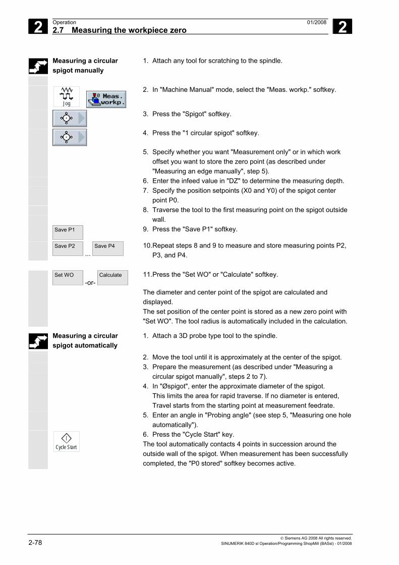
2 Operation 01/2008 2.7 Measuring the workpiece zero
2
© Siemens AG 2008 All rights reserved. 2-78 SINUMERIK 840D sl Operation/Programming ShopMill (BASsl) - 01/2008
Measuring a circular spigot manually
1. Attach any tool for scratching to the spindle.
Jog
2. In "Machine Manual" mode, select the "Meas. workp." softkey.
3. Press the "Spigot" softkey.
4. Press the "1 circular spigot" softkey.
5. Specify whether you want "Measurement only" or in which work offset you want to store the zero point (as described under "Measuring an edge manually", step 5).
6. Enter the infeed value in "DZ" to determine the measuring depth. 7. Specify the position setpoints (X0 and Y0) of the spigot center
point P0. 8. Traverse the tool to the first measuring point on the spigot outside
wall. Save P1
9. Press the "Save P1" softkey.
Save P2 ...
Save P4
10. Repeat steps 8 and 9 to measure and store measuring points P2, P3, and P4.
Set WO
-or- Calculate
11. Press the "Set WO" or "Calculate" softkey.
The diameter and center point of the spigot are calculated and displayed. The set position of the center point is stored as a new zero point with "Set WO". The tool radius is automatically included in the calculation.
Measuring a circular spigot automatically
1. Attach a 3D probe type tool to the spindle.
2. Move the tool until it is approximately at the center of the spigot. 3. Prepare the measurement (as described under "Measuring a
circular spigot manually", steps 2 to 7). 4. In "Øspigot", enter the approximate diameter of the spigot.
This limits the area for rapid traverse. If no diameter is entered, Travel starts from the starting point at measurement feedrate.
5. Enter an angle in "Probing angle" (see step 5, "Measuring one hole automatically").
Cycle Start
6. Press the "Cycle Start" key. The tool automatically contacts 4 points in succession around the outside wall of the spigot. When measurement has been successfully completed, the "P0 stored" softkey becomes active.
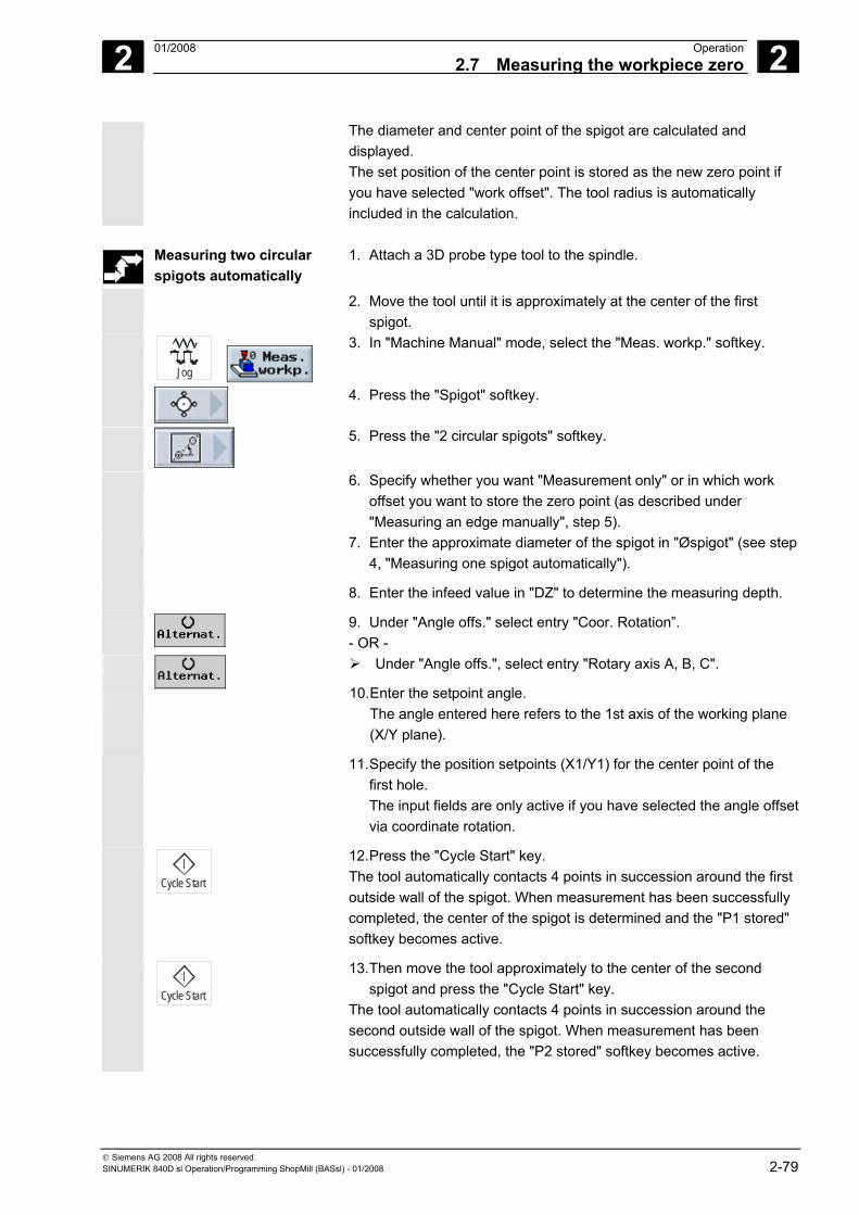
2 01/2008 Operation2.7 Measuring the workpiece zero
2
© Siemens AG 2008 All rights reserved. SINUMERIK 840D sl Operation/Programming ShopMill (BASsl) - 01/2008 2-79
The diameter and center point of the spigot are calculated and displayed. The set position of the center point is stored as the new zero point if you have selected "work offset". The tool radius is automatically included in the calculation.
Measuring two circular
spigots automatically 1. Attach a 3D probe type tool to the spindle.
2. Move the tool until it is approximately at the center of the first spigot.
Jog
3. In "Machine Manual" mode, select the "Meas. workp." softkey.
4. Press the "Spigot" softkey.
5. Press the "2 circular spigots" softkey.
6. Specify whether you want "Measurement only" or in which work offset you want to store the zero point (as described under "Measuring an edge manually", step 5).
7. Enter the approximate diameter of the spigot in "Øspigot" (see step 4, "Measuring one spigot automatically").
8. Enter the infeed value in "DZ" to determine the measuring depth.
9. Under "Angle offs." select entry "Coor. Rotation”. - OR -
Under "Angle offs.", select entry "Rotary axis A, B, C".
10. Enter the setpoint angle. The angle entered here refers to the 1st axis of the working plane (X/Y plane).
11. Specify the position setpoints (X1/Y1) for the center point of the first hole. The input fields are only active if you have selected the angle offset via coordinate rotation.
Cycle Start
12. Press the "Cycle Start" key. The tool automatically contacts 4 points in succession around the first outside wall of the spigot. When measurement has been successfully completed, the center of the spigot is determined and the "P1 stored" softkey becomes active.
Cycle Start
13. Then move the tool approximately to the center of the second spigot and press the "Cycle Start" key.
The tool automatically contacts 4 points in succession around the second outside wall of the spigot. When measurement has been successfully completed, the "P2 stored" softkey becomes active.
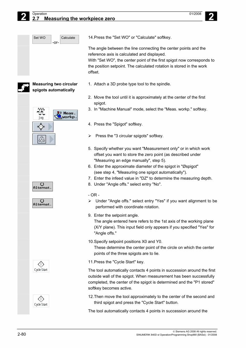
2 Operation 01/2008 2.7 Measuring the workpiece zero
2
© Siemens AG 2008 All rights reserved. 2-80 SINUMERIK 840D sl Operation/Programming ShopMill (BASsl) - 01/2008
Set WO -or-
Calculate
14. Press the "Set WO" or "Calculate" softkey.
The angle between the line connecting the center points and the reference axis is calculated and displayed. With "Set WO", the center point of the first spigot now corresponds to the position setpoint. The calculated rotation is stored in the work offset.
Measuring two circular
spigots automatically 1. Attach a 3D probe type tool to the spindle.
2. Move the tool until it is approximately at the center of the first spigot.
Jog
3. In "Machine Manual" mode, select the "Meas. workp." softkey.
4. Press the "Spigot" softkey.
Press the "3 circular spigots" softkey.
5. Specify whether you want "Measurement only" or in which work offset you want to store the zero point (as described under "Measuring an edge manually", step 5).
6. Enter the approximate diameter of the spigot in "Øspigot" (see step 4, "Measuring one spigot automatically").
7. Enter the infeed value in "DZ" to determine the measuring depth.
8. Under "Angle offs." select entry "No".
- OR -
Under "Angle offs." select entry "Yes" if you want alignment to be
performed with coordinate rotation.
9. Enter the setpoint angle. The angle entered here refers to the 1st axis of the working plane (X/Y plane). This input field only appears if you specified "Yes" for "Angle offs."
10. Specify setpoint positions X0 and Y0. These determine the center point of the circle on which the center points of the three spigots are to lie.
Cycle Start
11. Press the "Cycle Start" key.
The tool automatically contacts 4 points in succession around the first outside wall of the spigot. When measurement has been successfully completed, the center of the spigot is determined and the "P1 stored" softkey becomes active.
Cycle Start
12. Then move the tool approximately to the center of the second and third spigot and press the "Cycle Start" button.
The tool automatically contacts 4 points in succession around the
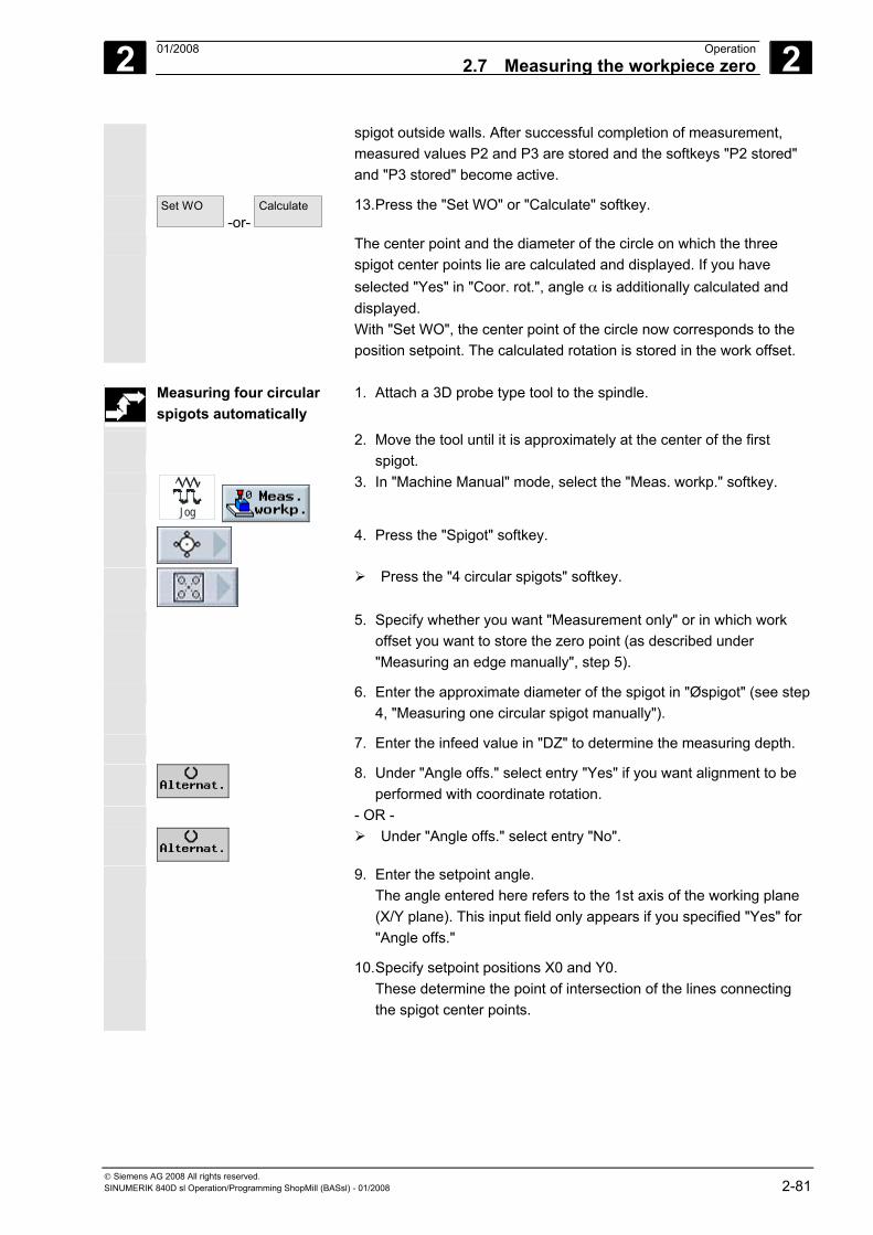
2 01/2008 Operation2.7 Measuring the workpiece zero
2
© Siemens AG 2008 All rights reserved. SINUMERIK 840D sl Operation/Programming ShopMill (BASsl) - 01/2008 2-81
spigot outside walls. After successful completion of measurement, measured values P2 and P3 are stored and the softkeys "P2 stored" and "P3 stored" become active.
Set WO -or-
Calculate
13. Press the "Set WO" or "Calculate" softkey.
The center point and the diameter of the circle on which the three spigot center points lie are calculated and displayed. If you have selected "Yes" in "Coor. rot.", angle α is additionally calculated and displayed. With "Set WO", the center point of the circle now corresponds to the position setpoint. The calculated rotation is stored in the work offset.
Measuring four circular
spigots automatically 1. Attach a 3D probe type tool to the spindle.
2. Move the tool until it is approximately at the center of the first spigot.
Jog
3. In "Machine Manual" mode, select the "Meas. workp." softkey.
4. Press the "Spigot" softkey.
Press the "4 circular spigots" softkey.
5. Specify whether you want "Measurement only" or in which work offset you want to store the zero point (as described under "Measuring an edge manually", step 5).
6. Enter the approximate diameter of the spigot in "Øspigot" (see step 4, "Measuring one circular spigot manually").
7. Enter the infeed value in "DZ" to determine the measuring depth.
8. Under "Angle offs." select entry "Yes" if you want alignment to be performed with coordinate rotation.
- OR -
Under "Angle offs." select entry "No".
9. Enter the setpoint angle. The angle entered here refers to the 1st axis of the working plane (X/Y plane). This input field only appears if you specified "Yes" for "Angle offs."
10. Specify setpoint positions X0 and Y0. These determine the point of intersection of the lines connecting the spigot center points.
2 Operation 01/2008 2.7 Measuring the workpiece zero
2
© Siemens AG 2008 All rights reserved. 2-82 SINUMERIK 840D sl Operation/Programming ShopMill (BASsl) - 01/2008
Cycle Start
11. Press the "Cycle Start" key.
The tool automatically contacts 4 points in succession around the first outside wall of the spigot. When measurement has been successfully completed, the center of the spigot is determined and the "P1 stored" softkey becomes active.
Cycle Start
12. Then move the tool approximately to the center of the second, third, and fourth spigot and press the "Cycle Start" button.
The tool automatically contacts 4 points in succession around the spigot outside walls. After successful completion of measurement, measured values P2, P3, and P4 are stored and the softkeys "P2 stored", "P3 stored", and "P4 stored" become active.
Set WO -or-
Calculate
13. Press the "Set WO" or "Calculate" softkey.
The spigot center points are connected diagonally and the intersection point of the two connecting lines calculated and displayed If you have selected "Yes" in "Coor. rot.", angle α is additionally calculated and displayed. With "Set WO", the intersection point now corresponds to the position setpoint. The calculated rotation is stored in the work offset.
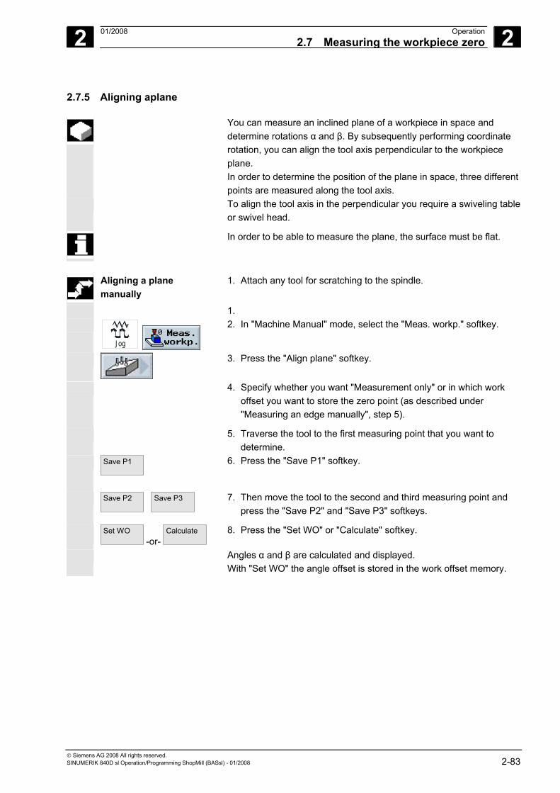
2 01/2008 Operation2.7 Measuring the workpiece zero
2
© Siemens AG 2008 All rights reserved. SINUMERIK 840D sl Operation/Programming ShopMill (BASsl) - 01/2008 2-83
2.7.5 Aligning aplane
You can measure an inclined plane of a workpiece in space and determine rotations α and β. By subsequently performing coordinate rotation, you can align the tool axis perpendicular to the workpiece plane. In order to determine the position of the plane in space, three different points are measured along the tool axis.
To align the tool axis in the perpendicular you require a swiveling table or swivel head.
In order to be able to measure the plane, the surface must be flat.
Aligning a plane
manually 1. Attach any tool for scratching to the spindle.
1.
Jog
2. In "Machine Manual" mode, select the "Meas. workp." softkey.
3. Press the "Align plane" softkey.
4. Specify whether you want "Measurement only" or in which work offset you want to store the zero point (as described under "Measuring an edge manually", step 5).
5. Traverse the tool to the first measuring point that you want to determine.
Save P1
6. Press the "Save P1" softkey.
Save P2
Save P3
7. Then move the tool to the second and third measuring point and press the "Save P2" and "Save P3" softkeys.
Set WO -or-
Calculate
8. Press the "Set WO" or "Calculate" softkey.
Angles α and β are calculated and displayed. With "Set WO" the angle offset is stored in the work offset memory.
2 Operation 01/2008 2.7 Measuring the workpiece zero
2
© Siemens AG 2008 All rights reserved. 2-84 SINUMERIK 840D sl Operation/Programming ShopMill (BASsl) - 01/2008
Aligning a plane automatically
1. Attach a 3D probe type tool to the spindle.
2. Traverse the tool to near the point you want to determine first.
Jog
3. In "Machine Manual" mode, select the "Meas. workp." softkey.
4. Press the "Align plane" softkey.
5. Specify whether you want "Measurement only" or in which work offset you want to store the zero point (as described under "Measuring an edge manually", step 5).
Cycle Start
6. Press the "Cycle Start" key. When measurement has been successfully completed, the measured value is stored and the "P1 stored" softkey becomes active.
Cycle Start
7. Then move the tool so that it is approximately above the second and then the third measuring point and press the "Cycle Start" button.
When measurement is complete, the "P2 stored" and "P3 stored" softkeys becomes active.
Set WO -or-
Calculate
8. Press the "Set WO" or "Calculate" softkey.
Angles α and β are calculated and displayed. With "Set WO" the angle offset is stored in the work offset memory.
2 01/2008 Operation2.7 Measuring the workpiece zero
2
© Siemens AG 2008 All rights reserved. SINUMERIK 840D sl Operation/Programming ShopMill (BASsl) - 01/2008 2-85
2.7.6 Corrections after measurement of the zero point
If you store the workpiece zero in a work offset, changes to the coordinate system or axis positions might be necessary in the following cases.
• Correcting the work offset causes the workpiece coordinate system to rotate, after which the tool can be aligned perpendicularly to the plane.
• Correcting the work offset necessitates positioning of the rotary axis in order to align the workpiece parallel with the coordinate system
Activation windows help you to adapt the coordinate system and the axis positions.
Activating work offset You stored the workpiece zero in a work offset that was not active
during measurement.
Set WO
When you press the "Set WO" softkey, the activation window opens asking whether you want to "Activate work offset xxx now?".
Press the "OK" softkey to activate the corrected work offset.
Aligning and retracting
the tool Rotating the workpiece coordinate system makes it necessary to realign the tool to the plane.
The activation window asking whether you want to "Position measuring probe perpendicular to plane?" is displayed.
Select "Yes" if you want to swivel into the plane.
The query "Positioning by swiveling! Retract?" appears.
Select the retract method you want to use.
Cycle Start
Press the "Cycle Start" key.
When the axis has been retracted the tool is realigned with the help of the swivel cycle. You can now measure again.
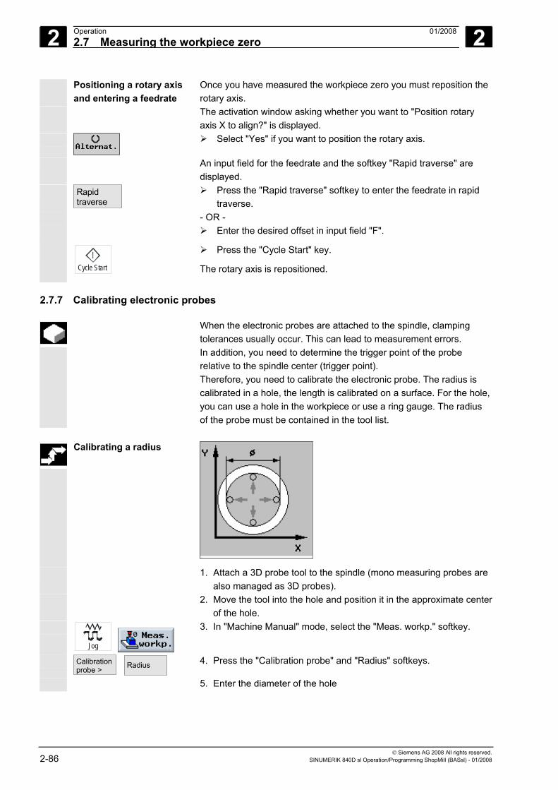
2 Operation 01/2008 2.7 Measuring the workpiece zero
2
© Siemens AG 2008 All rights reserved. 2-86 SINUMERIK 840D sl Operation/Programming ShopMill (BASsl) - 01/2008
Positioning a rotary axis and entering a feedrate
Once you have measured the workpiece zero you must reposition the rotary axis.
The activation window asking whether you want to "Position rotary axis X to align?" is displayed.
Select "Yes" if you want to position the rotary axis.
An input field for the feedrate and the softkey "Rapid traverse" are displayed.
Rapid traverse
Press the "Rapid traverse" softkey to enter the feedrate in rapid traverse.
- OR - Enter the desired offset in input field "F".
Cycle Start
Press the "Cycle Start" key.
The rotary axis is repositioned.
2.7.7 Calibrating electronic probes
When the electronic probes are attached to the spindle, clamping tolerances usually occur. This can lead to measurement errors. In addition, you need to determine the trigger point of the probe relative to the spindle center (trigger point). Therefore, you need to calibrate the electronic probe. The radius is calibrated in a hole, the length is calibrated on a surface. For the hole, you can use a hole in the workpiece or use a ring gauge. The radius of the probe must be contained in the tool list.
Calibrating a radius
1. Attach a 3D probe tool to the spindle (mono measuring probes are also managed as 3D probes).
2. Move the tool into the hole and position it in the approximate center of the hole.
Jog
3. In "Machine Manual" mode, select the "Meas. workp." softkey.
Calibration probe >
Radius
4. Press the "Calibration probe" and "Radius" softkeys.
5. Enter the diameter of the hole
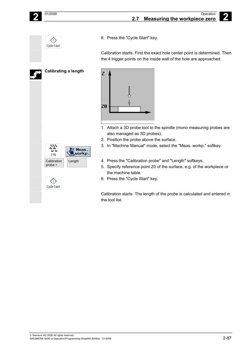
2 01/2008 Operation2.7 Measuring the workpiece zero
2
© Siemens AG 2008 All rights reserved. SINUMERIK 840D sl Operation/Programming ShopMill (BASsl) - 01/2008 2-87
Cycle Start
6. Press the "Cycle Start" key.
Calibration starts. First the exact hole center point is determined. Then the 4 trigger points on the inside wall of the hole are approached.
Calibrating a length
1. Attach a 3D probe tool to the spindle (mono measuring probes are also managed as 3D probes).
2. Position the probe above the surface.
Jog
3. In "Machine Manual" mode, select the "Meas. workp." softkey.
Calibration probe >
Length
4. Press the "Calibration probe" and "Length" softkeys. 5. Specify reference point Z0 of the surface, e.g. of the workpiece or
the machine table.
Cycle Start
6. Press the "Cycle Start" key.
Calibration starts. The length of the probe is calculated and entered in the tool list.
2 Operation 01/2008 2.8 Measuring a tool
2
© Siemens AG 2008 All rights reserved. 2-88 SINUMERIK 840D sl Operation/Programming ShopMill (BASsl) - 01/2008
2.8 Measuring a tool The various tool geometries must be taken into consideration while
the program is being executed. These are stored as so-called tool offset data in the tool list. Each time the tool is called, the control considers the tool offset data. You can determine the tool offset data, i.e. the length and radius or diameter, either manually or automatically (per measuring probe).
2.8.1 Measuring a tool manually
For manual measurement, move the tool manually to a known reference point to determine the tool length and the radius and diameter. ShopMill then calculates the tool offsets from the position of the toolholder reference point and the reference point.
When measuring the tool length you can either use the workpiece or a
fixed point in the machine coordinate system, e.g. a mechanical test socket or a fixed point in combination with a distance gauge as the reference point.
You can enter the position of the workpiece during measurement. The position of the fixed point on the other hand must be specified before you start measurement (see Section "Adjusting the fixed point").
When determining the radius/diameter, the workpiece is always the reference point. Depending on the setting in a machine data, you can measure the radius or the diameter of the tool.
Please also refer to the machine manufacturer's instructions.
Measuring length Workpiece reference point
Attach the tool you want to measure to the spindle.
Jog
Select the "Measure tool" softkey in "Machine Manual" mode.
Length manual >
Press the "Length manual" softkey.
Select the tool cutting edge D and the duplo number DP for the tool.
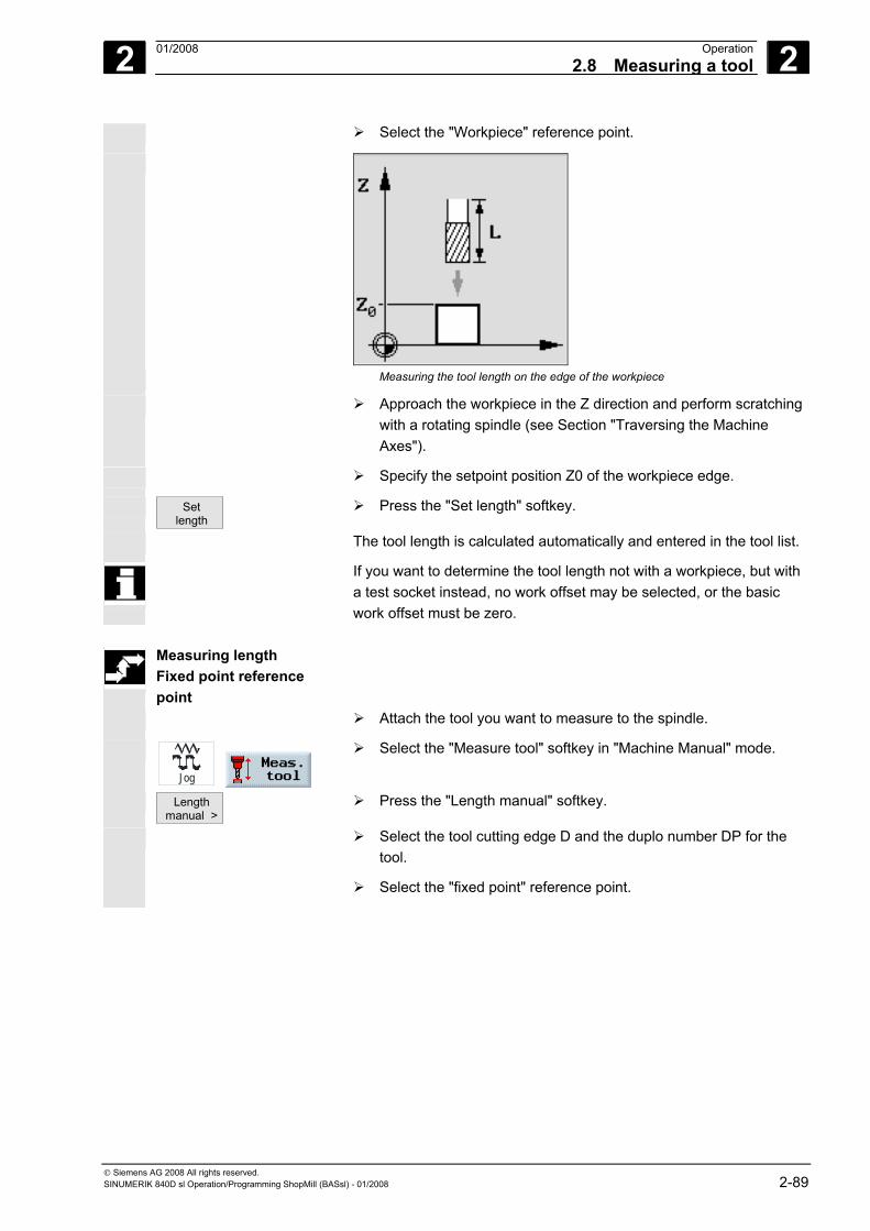
2 01/2008 Operation2.8 Measuring a tool
2
© Siemens AG 2008 All rights reserved. SINUMERIK 840D sl Operation/Programming ShopMill (BASsl) - 01/2008 2-89
Select the "Workpiece" reference point.
Measuring the tool length on the edge of the workpiece
Approach the workpiece in the Z direction and perform scratching with a rotating spindle (see Section "Traversing the Machine Axes").
Specify the setpoint position Z0 of the workpiece edge.
Set length
Press the "Set length" softkey.
The tool length is calculated automatically and entered in the tool list.
If you want to determine the tool length not with a workpiece, but with a test socket instead, no work offset may be selected, or the basic work offset must be zero.
Measuring length
Fixed point reference point
Attach the tool you want to measure to the spindle.
Jog
Select the "Measure tool" softkey in "Machine Manual" mode.
Length manual >
Press the "Length manual" softkey.
Select the tool cutting edge D and the duplo number DP for the tool.
Select the "fixed point" reference point.
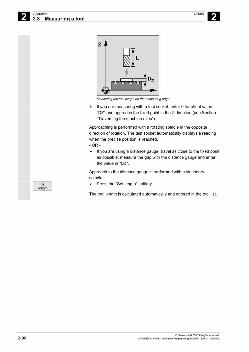
2 Operation 01/2008 2.8 Measuring a tool
2
© Siemens AG 2008 All rights reserved. 2-90 SINUMERIK 840D sl Operation/Programming ShopMill (BASsl) - 01/2008
Measuring the tool length on the measuring edge
If you are measuring with a test socket, enter 0 for offset value "DZ" and approach the fixed point in the Z direction (see Section "Traversing the machine axes").
Approaching is performed with a rotating spindle in the opposite direction of rotation. The test socket automatically displays a reading when the precise position is reached.
- OR - If you are using a distance gauge, travel as close to the fixed point
as possible, measure the gap with the distance gauge and enter the value in "DZ".
Approach to the distance gauge is performed with a stationary spindle.
Set length
Press the "Set length" softkey.
The tool length is calculated automatically and entered in the tool list.
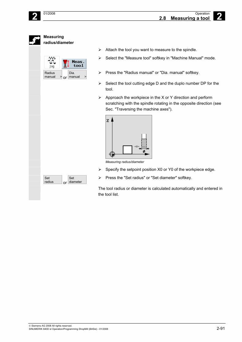
2 01/2008 Operation2.8 Measuring a tool
2
© Siemens AG 2008 All rights reserved. SINUMERIK 840D sl Operation/Programming ShopMill (BASsl) - 01/2008 2-91
Measuring radius/diameter
Attach the tool you want to measure to the spindle.
Jog
Select the "Measure tool" softkey in "Machine Manual" mode.
Radiusmanual > or
Dia.manual >
Press the "Radius manual" or "Dia. manual" softkey.
Select the tool cutting edge D and the duplo number DP for the tool.
Approach the workpiece in the X or Y direction and perform scratching with the spindle rotating in the opposite direction (see Sec. "Traversing the machine axes").
Measuring radius/diameter
Specify the setpoint position X0 or Y0 of the workpiece edge.
Setradius or
Setdiameter
Press the "Set radius" or "Set diameter" softkey.
The tool radius or diameter is calculated automatically and entered in the tool list.
2 Operation 01/2008 2.8 Measuring a tool
2
© Siemens AG 2008 All rights reserved. 2-92 SINUMERIK 840D sl Operation/Programming ShopMill (BASsl) - 01/2008
2.8.2 Calibrating a fixed point
If you want to use a fixed point as the reference point in manual measurement of the tool length, you must first determine the position of the fixed point relative to the machine zero.
You can use a mechanical test socket as the fixed point, for example.
Mount the test socket on the machine table in the machining space of the machine. Enter zero as the distance.
However, you can also use any fixed point on the machine in combination with a distance gauge. Enter the thickness of the plate in "DZ".
To calibrate the fixed point, use either a tool whose length is known (i.e. the tool length must be entered in the tool list) or the spindle directly.
The position of the fixed point may have already been determined by the machine manufacturer.
Please also refer to the machine manufacturer's instructions.
Traverse the tool or spindle to the fixed point.
Jog
Select the "Measure tool" softkey in "Machine Manual" mode.
Calibrate fixed point
Press the "Calibrate fixed point" softkey.
Enter an offset value for "DZ".
If you have used a distance gauge, enter the thickness of the plate used.
Calibrate
Press the "Calibrate" softkey.
The distance dimensions between machine zero and fixed point is calculated and entered in the machine data element.
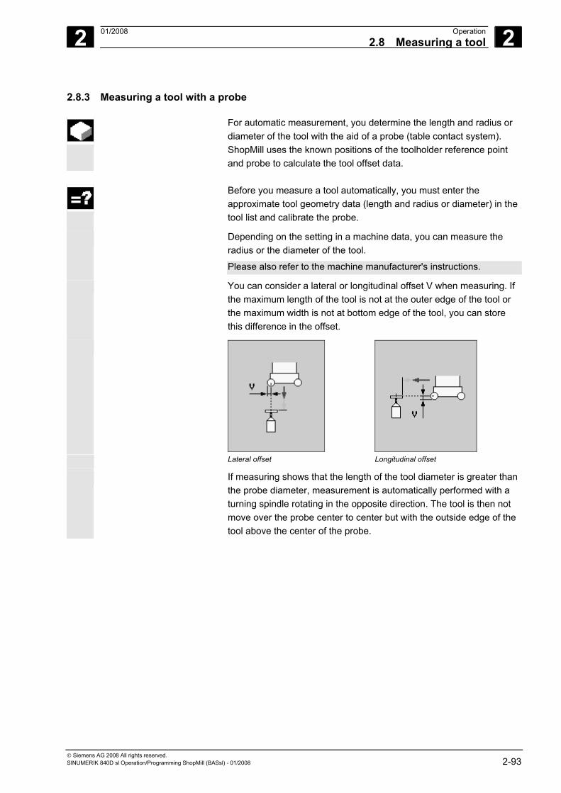
2 01/2008 Operation2.8 Measuring a tool
2
© Siemens AG 2008 All rights reserved. SINUMERIK 840D sl Operation/Programming ShopMill (BASsl) - 01/2008 2-93
2.8.3 Measuring a tool with a probe
For automatic measurement, you determine the length and radius or diameter of the tool with the aid of a probe (table contact system). ShopMill uses the known positions of the toolholder reference point and probe to calculate the tool offset data.
Before you measure a tool automatically, you must enter the
approximate tool geometry data (length and radius or diameter) in the tool list and calibrate the probe.
Depending on the setting in a machine data, you can measure the radius or the diameter of the tool.
Please also refer to the machine manufacturer's instructions.
You can consider a lateral or longitudinal offset V when measuring. If the maximum length of the tool is not at the outer edge of the tool or the maximum width is not at bottom edge of the tool, you can store this difference in the offset.
Lateral offset Longitudinal offset
If measuring shows that the length of the tool diameter is greater than the probe diameter, measurement is automatically performed with a turning spindle rotating in the opposite direction. The tool is then not move over the probe center to center but with the outside edge of the tool above the center of the probe.
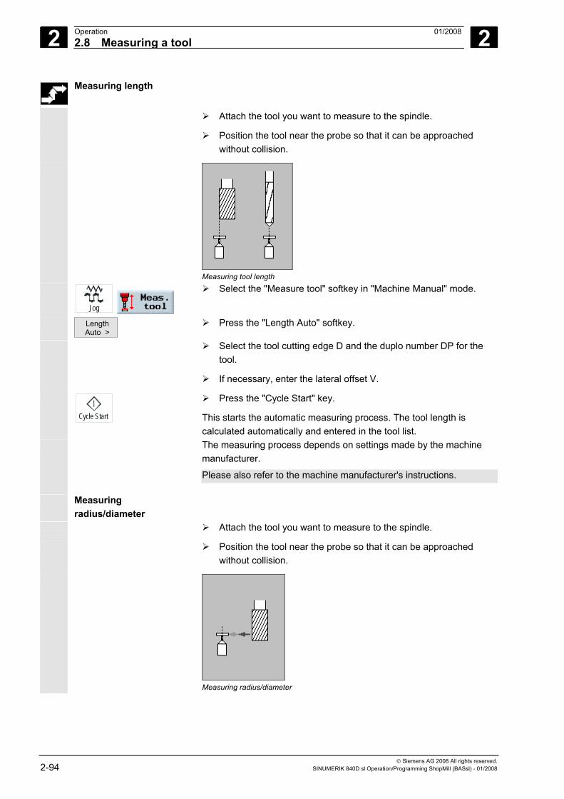
2 Operation 01/2008 2.8 Measuring a tool
2
© Siemens AG 2008 All rights reserved. 2-94 SINUMERIK 840D sl Operation/Programming ShopMill (BASsl) - 01/2008
Measuring length
Attach the tool you want to measure to the spindle.
Position the tool near the probe so that it can be approached without collision.
Measuring tool length
Jog
Select the "Measure tool" softkey in "Machine Manual" mode.
Length Auto >
Press the "Length Auto" softkey.
Select the tool cutting edge D and the duplo number DP for the tool.
If necessary, enter the lateral offset V.
Cycle Start
Press the "Cycle Start" key.
This starts the automatic measuring process. The tool length is calculated automatically and entered in the tool list.
The measuring process depends on settings made by the machine manufacturer.
Please also refer to the machine manufacturer's instructions.
Measuring radius/diameter
Attach the tool you want to measure to the spindle.
Position the tool near the probe so that it can be approached without collision.
Measuring radius/diameter
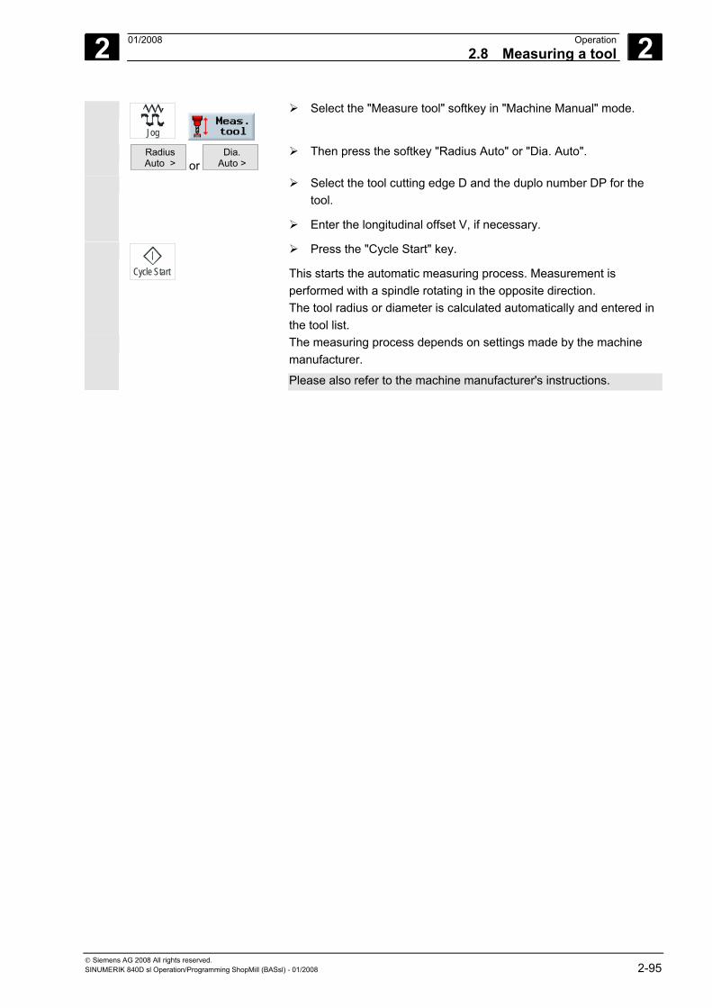
2 01/2008 Operation2.8 Measuring a tool
2
© Siemens AG 2008 All rights reserved. SINUMERIK 840D sl Operation/Programming ShopMill (BASsl) - 01/2008 2-95
Jog
Select the "Measure tool" softkey in "Machine Manual" mode.
Radius Auto > or
Dia. Auto >
Then press the softkey "Radius Auto" or "Dia. Auto".
Select the tool cutting edge D and the duplo number DP for the tool.
Enter the longitudinal offset V, if necessary.
Cycle Start
Press the "Cycle Start" key.
This starts the automatic measuring process. Measurement is performed with a spindle rotating in the opposite direction. The tool radius or diameter is calculated automatically and entered in the tool list.
The measuring process depends on settings made by the machine manufacturer.
Please also refer to the machine manufacturer's instructions.
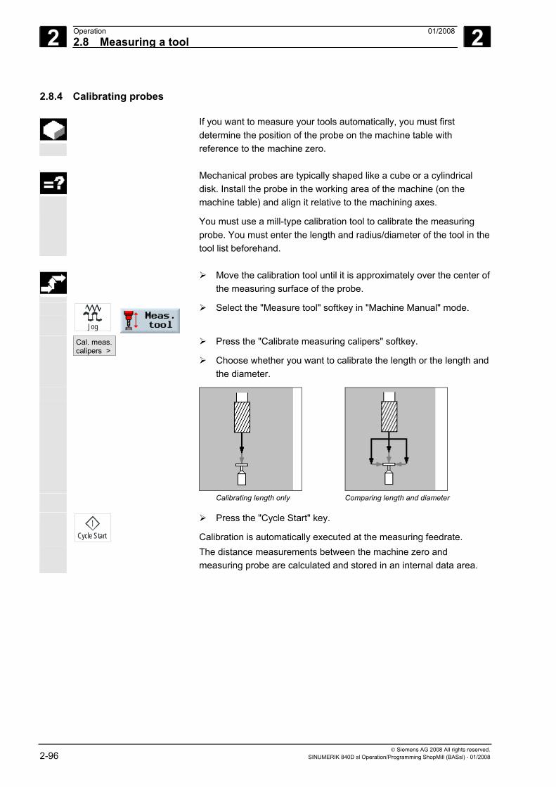
2 Operation 01/2008 2.8 Measuring a tool
2
© Siemens AG 2008 All rights reserved. 2-96 SINUMERIK 840D sl Operation/Programming ShopMill (BASsl) - 01/2008
2.8.4 Calibrating probes
If you want to measure your tools automatically, you must first determine the position of the probe on the machine table with reference to the machine zero.
Mechanical probes are typically shaped like a cube or a cylindrical
disk. Install the probe in the working area of the machine (on the machine table) and align it relative to the machining axes.
You must use a mill-type calibration tool to calibrate the measuring probe. You must enter the length and radius/diameter of the tool in the tool list beforehand.
Move the calibration tool until it is approximately over the center of
the measuring surface of the probe.
Jog
Select the "Measure tool" softkey in "Machine Manual" mode.
Cal. meas. calipers >
Press the "Calibrate measuring calipers" softkey.
Choose whether you want to calibrate the length or the length and the diameter.
Calibrating length only Comparing length and diameter
Cycle Start
Press the "Cycle Start" key.
Calibration is automatically executed at the measuring feedrate. The distance measurements between the machine zero and
measuring probe are calculated and stored in an internal data area.
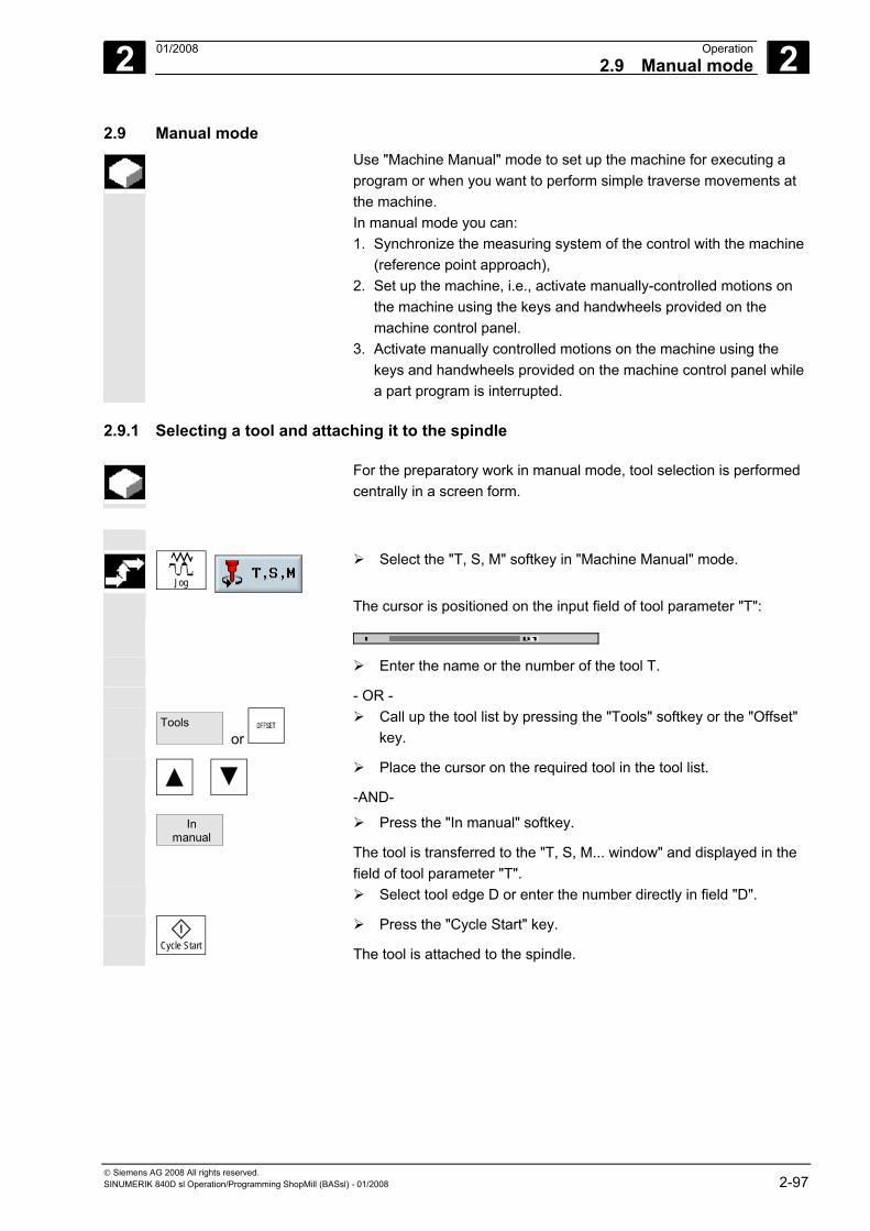
2 01/2008 Operation2.9 Manual mode
2
© Siemens AG 2008 All rights reserved. SINUMERIK 840D sl Operation/Programming ShopMill (BASsl) - 01/2008 2-97
2.9 Manual mode Use "Machine Manual" mode to set up the machine for executing a
program or when you want to perform simple traverse movements at the machine. In manual mode you can: 1. Synchronize the measuring system of the control with the machine
(reference point approach), 2. Set up the machine, i.e., activate manually-controlled motions on
the machine using the keys and handwheels provided on the machine control panel.
3. Activate manually controlled motions on the machine using the keys and handwheels provided on the machine control panel while a part program is interrupted.
2.9.1 Selecting a tool and attaching it to the spindle
For the preparatory work in manual mode, tool selection is performed centrally in a screen form.
Jog
Select the "T, S, M" softkey in "Machine Manual" mode.
The cursor is positioned on the input field of tool parameter "T":
Enter the name or the number of the tool T.
- OR - Tools
or Call up the tool list by pressing the "Tools" softkey or the "Offset"
key.
Place the cursor on the required tool in the tool list.
-AND-
In manual
Press the "In manual" softkey.
The tool is transferred to the "T, S, M... window" and displayed in the field of tool parameter "T".
Select tool edge D or enter the number directly in field "D".
Cycle Start
Press the "Cycle Start" key.
The tool is attached to the spindle.

2 Operation 01/2008 2.9 Manual mode
2
© Siemens AG 2008 All rights reserved. 2-98 SINUMERIK 840D sl Operation/Programming ShopMill (BASsl) - 01/2008
2.9.2 Entering a tool in the list and attaching it to the spindle
Preparing for loading
Jog
Select the "T, S, M" softkey in "Machine Manual" mode.
The cursor is positioned on the input field of tool parameter "T".
Entering tool in tool list
or
Tools
Press the "Offset" or "Tools" softkey to open the tool list.
Enter a new tool (as described in Section "Tools and tool offsets").
In manual
Press the "In manual" softkey.
You automatically return to function "T,S,M, …". The tool name is now entered in the input field of tool parameter "T".
Performing a tool change
Cycle Start
Press the "Cycle Start" key.
Tool change is enabled.
The loaded tool is marked by a spindle symbol in the tool list.
Now load the tool manually into the spindle as described in the machine manufacturer's instruction manual.
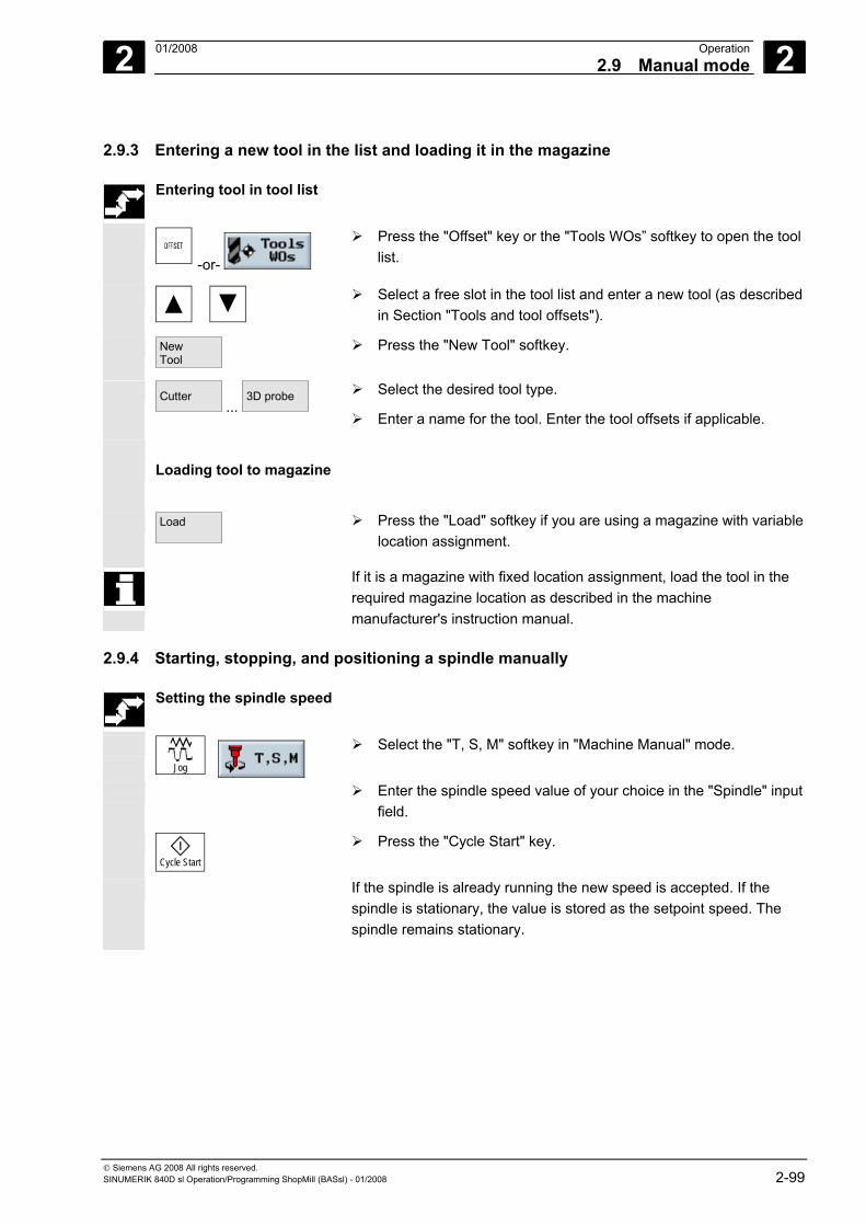
2 01/2008 Operation2.9 Manual mode
2
© Siemens AG 2008 All rights reserved. SINUMERIK 840D sl Operation/Programming ShopMill (BASsl) - 01/2008 2-99
2.9.3 Entering a new tool in the list and loading it in the magazine
Entering tool in tool list
-or-
Press the "Offset" key or the "Tools WOs” softkey to open the tool list.
Select a free slot in the tool list and enter a new tool (as described in Section "Tools and tool offsets").
New Tool
Press the "New Tool" softkey.
Cutter ...
3D probe
Select the desired tool type.
Enter a name for the tool. Enter the tool offsets if applicable.
Loading tool to magazine
Load
Press the "Load" softkey if you are using a magazine with variable location assignment.
If it is a magazine with fixed location assignment, load the tool in the required magazine location as described in the machine manufacturer's instruction manual.
2.9.4 Starting, stopping, and positioning a spindle manually
Setting the spindle speed
Jog
Select the "T, S, M" softkey in "Machine Manual" mode.
Enter the spindle speed value of your choice in the "Spindle" input field.
Cycle Start
Press the "Cycle Start" key.
If the spindle is already running the new speed is accepted. If the spindle is stationary, the value is stored as the setpoint speed. The spindle remains stationary.
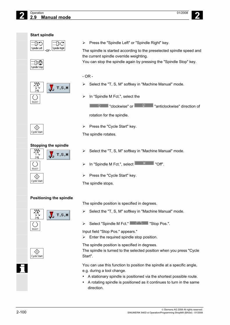
2 Operation 01/2008 2.9 Manual mode
2
© Siemens AG 2008 All rights reserved. 2-100 SINUMERIK 840D sl Operation/Programming ShopMill (BASsl) - 01/2008
Start spindle
Spindle Left -or- Spindle Right
Press the "Spindle Left" or "Spindle Right" key.
The spindle is started according to the preselected spindle speed and the current spindle override weighting.
Spindle Stop
You can stop the spindle again by pressing the "Spindle Stop" key.
- OR -
Jog
Select the "T, S, M" softkey in "Machine Manual" mode.
In “Spindle M Fct.", select the
"clockwise" or "anticlockwise" direction of
rotation for the spindle.
Cycle Start
Press the "Cycle Start" key.
The spindle rotates. Stopping the spindle
Jog
Select the "T, S, M" softkey in "Machine Manual" mode.
In "Spindle M Fct.", select "Off".
Cycle Start
Press the "Cycle Start" key.
The spindle stops.
Positioning the spindle The spindle position is specified in degrees.
Jog
Select the "T, S, M" softkey in "Machine Manual" mode.
Select "Spindle M Fct." "Stop Pos.".
Input field "Stop Pos." appears." Enter the required spindle stop position.
The spindle position is specified in degrees.
Cycle Start
The spindle is turned to the selected position when you press "Cycle Start".
You can use this function to position the spindle at a specific angle, e.g. during a tool change. • A stationary spindle is positioned via the shortest possible route. • A rotating spindle is positioned as it continues to turn in the same
direction.
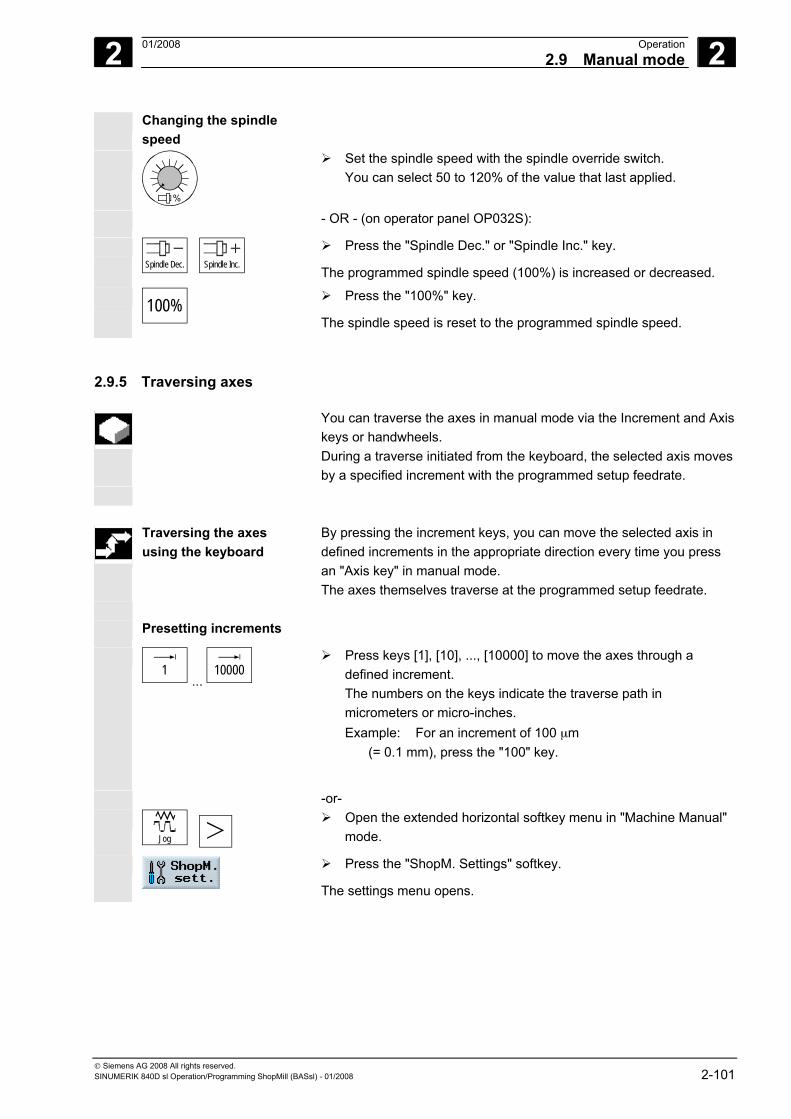
2 01/2008 Operation2.9 Manual mode
2
© Siemens AG 2008 All rights reserved. SINUMERIK 840D sl Operation/Programming ShopMill (BASsl) - 01/2008 2-101
Changing the spindle speed
%
Set the spindle speed with the spindle override switch. You can select 50 to 120% of the value that last applied.
- OR - (on operator panel OP032S):
Spindle Dec. Spindle Inc.
Press the "Spindle Dec." or "Spindle Inc." key.
The programmed spindle speed (100%) is increased or decreased.
100%
Press the "100%" key.
The spindle speed is reset to the programmed spindle speed.
2.9.5 Traversing axes
You can traverse the axes in manual mode via the Increment and Axis keys or handwheels. During a traverse initiated from the keyboard, the selected axis moves by a specified increment with the programmed setup feedrate.
Traversing the axes using the keyboard
By pressing the increment keys, you can move the selected axis in defined increments in the appropriate direction every time you press an "Axis key" in manual mode. The axes themselves traverse at the programmed setup feedrate.
Presetting increments
1
... 10000
Press keys [1], [10], ..., [10000] to move the axes through a defined increment. The numbers on the keys indicate the traverse path in micrometers or micro-inches. Example: For an increment of 100 μm (= 0.1 mm), press the "100" key.
-or-
Jog
Open the extended horizontal softkey menu in "Machine Manual" mode.
Press the "ShopM. Settings" softkey.
The settings menu opens.
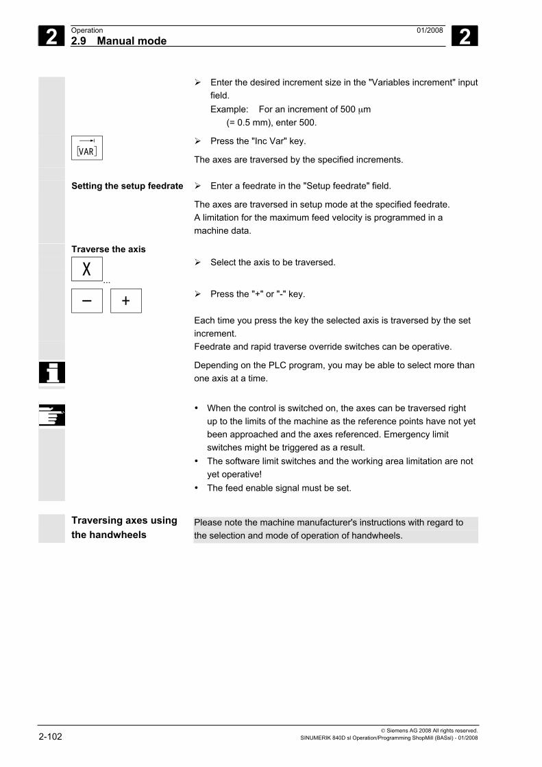
2 Operation 01/2008 2.9 Manual mode
2
© Siemens AG 2008 All rights reserved. 2-102 SINUMERIK 840D sl Operation/Programming ShopMill (BASsl) - 01/2008
Enter the desired increment size in the "Variables increment" input field. Example: For an increment of 500 μm (= 0.5 mm), enter 500.
VAR
Press the "Inc Var" key.
The axes are traversed by the specified increments. Setting the setup feedrate Enter a feedrate in the "Setup feedrate" field.
The axes are traversed in setup mode at the specified feedrate. A limitation for the maximum feed velocity is programmed in a machine data.
Traverse the axis X
...
Select the axis to be traversed.
+
Press the "+" or "-" key.
Each time you press the key the selected axis is traversed by the set increment.
Feedrate and rapid traverse override switches can be operative.
Depending on the PLC program, you may be able to select more than one axis at a time.
• When the control is switched on, the axes can be traversed right
up to the limits of the machine as the reference points have not yet been approached and the axes referenced. Emergency limit switches might be triggered as a result.
• The software limit switches and the working area limitation are not yet operative!
• The feed enable signal must be set.
Traversing axes using
the handwheels Please note the machine manufacturer's instructions with regard to the selection and mode of operation of handwheels.
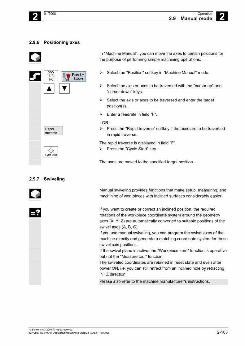
2 01/2008 Operation2.9 Manual mode
2
© Siemens AG 2008 All rights reserved. SINUMERIK 840D sl Operation/Programming ShopMill (BASsl) - 01/2008 2-103
2.9.6 Positioning axes
In "Machine Manual", you can move the axes to certain positions for the purpose of performing simple machining operations.
Jog
Select the "Position" softkey in "Machine Manual" mode.
Select the axis or axes to be traversed with the "cursor up" and "cursor down" keys.
Select the axis or axes to be traversed and enter the target position(s).
Enter a feedrate in field "F".
- OR - Rapid
traverse Press the "Rapid traverse" softkey if the axes are to be traversed
in rapid traverse.
The rapid traverse is displayed in field "F".
Cycle Start
Press the "Cycle Start" key.
The axes are moved to the specified target position.
2.9.7 Swiveling
Manual swiveling provides functions that make setup, measuring, and machining of workpieces with inclined surfaces considerably easier.
If you want to create or correct an inclined position, the required
rotations of the workpiece coordinate system around the geometry axes (X, Y, Z) are automatically converted to suitable positions of the swivel axes (A, B, C). If you use manual swiveling, you can program the swivel axes of the machine directly and generate a matching coordinate system for those swivel axis positions.
If the swivel plane is active, the "Workpiece zero" function is operative but not the "Measure tool" function.
The swiveled coordinates are retained in reset state and even after power ON, i.e. you can still retract from an inclined hole by retracting in +Z direction.
Please also refer to the machine manufacturer's instructions.
2 Operation 01/2008 2.9 Manual mode
2
© Siemens AG 2008 All rights reserved. 2-104 SINUMERIK 840D sl Operation/Programming ShopMill (BASsl) - 01/2008
The following provides an explanation of the most important parameters for swiveling:
Retract Before swiveling the axes you can move the tool to a safe retraction position. The retraction methods available to you are defined in the "Retraction position" parameter during set-up of the swivel data set.
Please also refer to the machine manufacturer's instructions.
Warning
You must select a retraction position that precludes collision between the tool and workpiece during swiveling.
Swivel method Swiveling can be axis by axis or direct. • Axis-by-axis swiveling is based on the coordinate system of the
workpiece (X, Y, Z). The coordinate axis sequence can be selected freely. The rotations are applied in the selected order. ShopMill calculates the rotation of the rotary axes (A, B, C) based on those values.
• In direct swiveling, the positions of the rotary axes are specified. ShopMill calculates a suitable new coordinate system based on those values. The tool axis is aligned in the Z direction. You can derive the resulting direction of the X and Y axis by traversing the axes.
The positive direction of each rotation for the different swivel methods is shown in the help displays.
Direction In swivel systems with 2 rotary axes, a particular plane can be reached in two different ways. You can choose between these two different positions in the "Direction" parameter. The +/- corresponds to the larger or smaller value of a rotary axis. This may affect the working area. When the swivel data set is set up, the entries in the "Direction" parameter determine for which rotary axis you can select each of the two settings.
Please also refer to the machine manufacturer's instructions.
If one of the two positions cannot be reached for mechanical reasons, the alternative position is automatically selected irrespective of the setting of the "Direction" parameter.
Fixing the tool tip To avoid collisions, you can use the 5-axis transformation (software option) to retain the position of the tool tip during swiveling. This function must be enabled when you set up "Swivel" in the "Correction T" parameter.
Please also refer to the machine manufacturer's instructions.
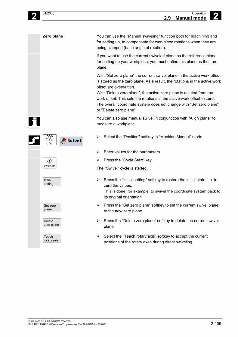
2 01/2008 Operation2.9 Manual mode
2
© Siemens AG 2008 All rights reserved. SINUMERIK 840D sl Operation/Programming ShopMill (BASsl) - 01/2008 2-105
Zero plane You can use the "Manual swiveling" function both for machining and for setting up, to compensate for workpiece rotations when they are being clamped (base angle of rotation).
If you want to use the current swiveled plane as the reference plane for setting up your workpiece, you must define this plane as the zero plane.
With "Set zero plane" the current swivel plane in the active work offset is stored as the zero plane. As a result, the rotations in the active work offset are overwritten. With "Delete zero plane", the active zero plane is deleted from the work offset. This sets the rotations in the active work offset to zero. The overall coordinate system does not change with "Set zero plane" or "Delete zero plane".
You can also use manual swivel in conjunction with "Align plane" to measure a workpiece.
Jog
Select the "Position" softkey in "Machine Manual" mode.
Enter values for the parameters.
Cycle Start
Press the "Cycle Start" key.
The "Swivel" cycle is started. Initial
setting Press the "Initial setting" softkey to restore the initial state, i.e. to
zero the values. This is done, for example, to swivel the coordinate system back to its original orientation.
Set zero plane
Press the "Set zero plane" softkey to set the current swivel plane to the new zero plane.
Delete zero plane
Press the "Delete zero plane" softkey to delete the current swivel plane.
Teach rotary axis
Select the "Teach rotary axis" softkey to accept the current positions of the rotary axes during direct swiveling.
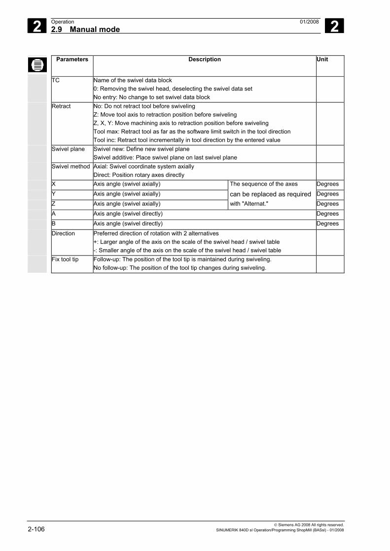
2 Operation 01/2008 2.9 Manual mode
2
© Siemens AG 2008 All rights reserved. 2-106 SINUMERIK 840D sl Operation/Programming ShopMill (BASsl) - 01/2008
Parameters Description Unit
TC Name of the swivel data block 0: Removing the swivel head, deselecting the swivel data set No entry: No change to set swivel data block
Retract No: Do not retract tool before swiveling Z: Move tool axis to retraction position before swiveling Z, X, Y: Move machining axis to retraction position before swiveling Tool max: Retract tool as far as the software limit switch in the tool direction Tool inc: Retract tool incrementally in tool direction by the entered value
Swivel plane Swivel new: Define new swivel plane Swivel additive: Place swivel plane on last swivel plane
Swivel method Axial: Swivel coordinate system axially Direct: Position rotary axes directly
X Axis angle (swivel axially) The sequence of the axes Degrees Y Axis angle (swivel axially) can be replaced as required Degrees Z Axis angle (swivel axially) with "Alternat." Degrees A Axis angle (swivel directly) Degrees B Axis angle (swivel directly) Degrees Direction Preferred direction of rotation with 2 alternatives
+: Larger angle of the axis on the scale of the swivel head / swivel table -: Smaller angle of the axis on the scale of the swivel head / swivel table
Fix tool tip Follow-up: The position of the tool tip is maintained during swiveling. No follow-up: The position of the tool tip changes during swiveling.
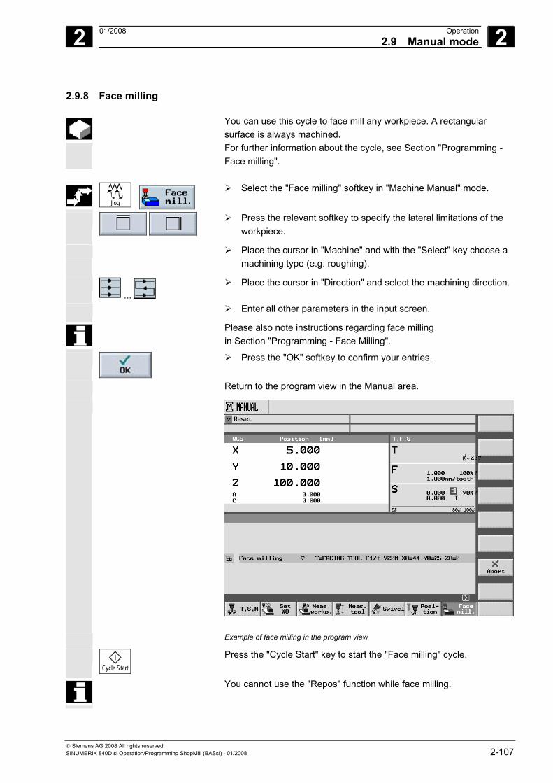
2 01/2008 Operation2.9 Manual mode
2
© Siemens AG 2008 All rights reserved. SINUMERIK 840D sl Operation/Programming ShopMill (BASsl) - 01/2008 2-107
2.9.8 Face milling
You can use this cycle to face mill any workpiece. A rectangular surface is always machined. For further information about the cycle, see Section "Programming - Face milling".
Jog
Select the "Face milling" softkey in "Machine Manual" mode.
Press the relevant softkey to specify the lateral limitations of the workpiece.
Place the cursor in "Machine" and with the "Select" key choose a machining type (e.g. roughing).
...
Place the cursor in "Direction" and select the machining direction.
Enter all other parameters in the input screen.
Please also note instructions regarding face milling in Section "Programming - Face Milling".
Press the "OK" softkey to confirm your entries.
Return to the program view in the Manual area.
Example of face milling in the program view
Cycle Start
Press the "Cycle Start" key to start the "Face milling" cycle.
You cannot use the "Repos" function while face milling.
2 Operation 01/2008 2.9 Manual mode
2
© Siemens AG 2008 All rights reserved. 2-108 SINUMERIK 840D sl Operation/Programming ShopMill (BASsl) - 01/2008
2.9.9 Settings for manual mode
For manual mode, you can select the central machine functions and work offsets and set the unit of measurement. Machine functions (M functions) are functions that are additionally provided by the machine manufacturer.
Please also refer to the machine manufacturer's instructions. In manual mode, you can display the axis positions and distance-defining parameters either in "mm" or "inches". However, tool offsets and work offsets remain in the original unit of measurement in which the machine was set (see Section "Switching over the unit of measurement millimeter/inch").
Selecting a gear stage If your machine has a separate gear unit for spindles, you can select a
gear stage.
Jog
Select the "T, S, M" softkey in "Machine Manual" mode.
Position the cursor in the "Gear stage" field.
Select the gear stage you want to use (e.g. "auto").
This gear stage will be active the next time you press the "Cycle Start" key.
Selecting an M function
Jog
Select the "T, S, M" softkey in "Machine Manual" mode.
Enter the number of the desired M function in the "Misc M fct." parameter field. Refer to the machine manufacturer's table for the correlation between the meaning and number of the function.
The M function will be active the next time you press the "Cycle Start" key.
Selecting work offset
Jog
Select the "T, S, M" softkey in "Machine Manual" mode.
In the "Work offset" field, enter a work offset (e.g. base).
- OR -
2 01/2008 Operation2.9 Manual mode
2
© Siemens AG 2008 All rights reserved. SINUMERIK 840D sl Operation/Programming ShopMill (BASsl) - 01/2008 2-109
Work offset
Press the "Work offset" softkey to open the work offset list.
In manual
Place the cursor on the required zero point and press the "In manual" softkey.
The work offset will be active the next time you press the "Cycle Start" key.
Setting the unit of
measurement The selected unit of measurement affects the actual value display and distance-defining parameters. The setting applies to the Manual area and remains valid until you switch to the other unit. In Automatic mode, the unit of measurement displayed in the program header is always activated.
Jog
Select the "T, S, M" softkey in "Machine Manual" mode.
Select a unit of measurement from the "Unit of measurement" box.
The unit of measurement will be active in manual mode the next time you press the "Cycle Start" key.
Selecting a tool axis If your machine has a swivel-mounted work spindle, you can select
the machining plane in the "Tool axis" selection field in menu "T, S, M".
This parameter is relevant for all screen forms in the Manual area, i.e. it influences the parameter displays for face milling or measurements. In addition, the plane setting determines how tool offsets are calculated in workpiece and tool measurements.
Jog
Select the "T, S, M" softkey in "Machine Manual" mode.
Select an axis from the "Tool axis" box.
That tool axis will be active in manual mode the next time you press the "Cycle Start" key.
For instructions on how to swivel the spindle, please refer to the machine manufacturer's instructions.
2 Operation 01/2008 2.9 Manual mode
2
© Siemens AG 2008 All rights reserved. 2-110 SINUMERIK 840D sl Operation/Programming ShopMill (BASsl) - 01/2008
Changing default settings
Jog
Select the "Expand" softkey in "Machine Manual" mode to expand the softkey bar.
Press the "ShopM. sett." softkey.
The “ShopMill settings” menu opens.
Retraction plane In the "Retraction plane" box enter the retraction position above the workpiece to be approached during face milling in rapid traverse in manual mode.
Safety distance In the "Safety clearance" box, enter the position to which the axis is to traverse in rapid traverse. The safety clearance is the distance between the tool tip and the workpiece surface. As soon as the safety clearance is reached, the programmed face milling cycle is executed at machining feedrate.
Setup feed rate In the "setup feedrate" box enter the feedrate with which you want to traverse the axes in manual mode.
Variable increment In the "variable increment" box enter an increment for traversing the axes in manual mode not at a fixed increment but at a variable increment.
Press the "Back" softkey.
The "ShopMill settings" menu box closes. These settings remain valid until you change them.
These settings are made for the programs in the program header.
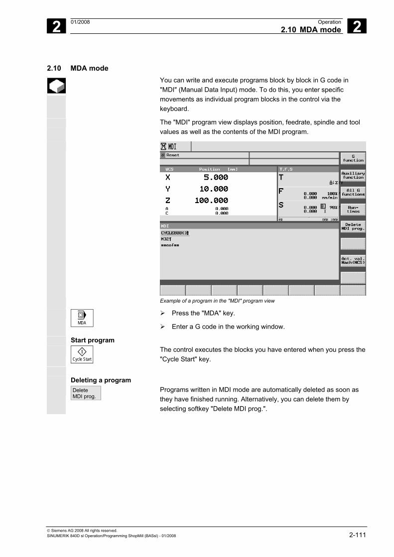
2 01/2008 Operation2.10 MDA mode
2
© Siemens AG 2008 All rights reserved. SINUMERIK 840D sl Operation/Programming ShopMill (BASsl) - 01/2008 2-111
2.10 MDA mode You can write and execute programs block by block in G code in
"MDI" (Manual Data Input) mode. To do this, you enter specific movements as individual program blocks in the control via the keyboard.
The "MDI" program view displays position, feedrate, spindle and tool values as well as the contents of the MDI program.
Example of a program in the "MDI" program view
MDA
Press the "MDA" key.
Enter a G code in the working window.
Start program
Cycle Start
The control executes the blocks you have entered when you press the "Cycle Start" key.
Deleting a program Delete
MDI prog.
Programs written in MDI mode are automatically deleted as soon as they have finished running. Alternatively, you can delete them by selecting softkey "Delete MDI prog.".
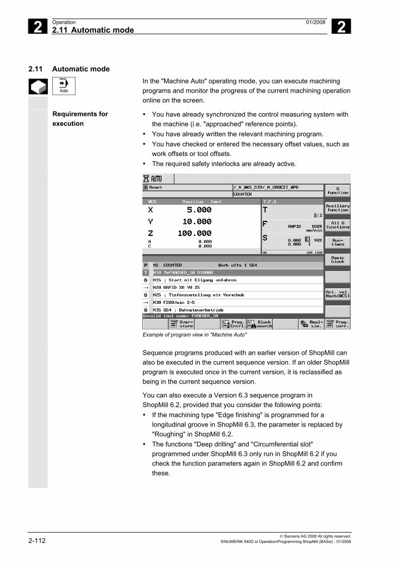
2 Operation 01/2008 2.11 Automatic mode
2
© Siemens AG 2008 All rights reserved. 2-112 SINUMERIK 840D sl Operation/Programming ShopMill (BASsl) - 01/2008
2.11 Automatic mode
Auto
In the "Machine Auto" operating mode, you can execute machining programs and monitor the progress of the current machining operation online on the screen.
Requirements for execution
• You have already synchronized the control measuring system with the machine (i.e. "approached" reference points).
• You have already written the relevant machining program. • You have checked or entered the necessary offset values, such as
work offsets or tool offsets. • The required safety interlocks are already active.
Example of program view in "Machine Auto"
Sequence programs produced with an earlier version of ShopMill can
also be executed in the current sequence version. If an older ShopMill program is executed once in the current version, it is reclassified as being in the current sequence version.
You can also execute a Version 6.3 sequence program in ShopMill 6.2, provided that you consider the following points: • If the machining type "Edge finishing" is programmed for a
longitudinal groove in ShopMill 6.3, the parameter is replaced by "Roughing" in ShopMill 6.2.
• The functions "Deep drilling" and "Circumferential slot" programmed under ShopMill 6.3 only run in ShopMill 6.2 if you check the function parameters again in ShopMill 6.2 and confirm these.

2 01/2008 Operation2.11 Automatic mode
2
© Siemens AG 2008 All rights reserved. SINUMERIK 840D sl Operation/Programming ShopMill (BASsl) - 01/2008 2-113
When a ShopMill program with Version 6.3 is executed in ShopMill 6.2, it is deemed to be a Version-6.2 program.
2.11.1 Switchover between "T, F, S", "G functions", and "Auxiliary functions" displays
While the workpiece is being machined, if you want to know, for example, whether the tool tip radius compensation is currently active or which unit of measurement is being used, you can activate display of the G functions or auxiliary functions.
G Functions
16 different G groups are displayed under "G function". Within a G group, only the G functions that are currently active in the NCK appear.
As an alternative, all G groups with all associated G functions are listed in "All G Func.".
Auxiliary functions Auxiliary functions include M and H functions preprogrammed by the machine manufacturer, which pass parameters to the PLC to trigger reactions defined by the manufacturer.
Please also refer to the machine manufacturer's instructions. A maximum of five M functions and three H functions are displayed.
When executing a sequential control program, you can also display the G functions that are currently active in the NCK, as the ShopMill functions are converted to G code internally.
G function
Press the "G function" softkey in "Machine Manual" or "Machine Auto" mode.
Instead of parameters T, F and S, the currently active G functions within a G group will be displayed. If you press the "G function" softkey again, the "T, F, S" status display reappears.
- OR -
AllG func.
Press the "All G func." softkey.
Instead of parameters T, F and S, all G groups with G functions are now listed. If you select the "All G func." softkey again, the "T, F, S" status display reappears.
- OR -
Auxiliaryfunction
Press the "Auxiliary function" softkey.
Instead of parameters T, F and S, the currently active auxiliary functions will be displayed. If you press the "Auxiliary function" softkey again, the "T, F, S" status display reappears.
2 Operation 01/2008 2.11 Automatic mode
2
© Siemens AG 2008 All rights reserved. 2-114 SINUMERIK 840D sl Operation/Programming ShopMill (BASsl) - 01/2008
2.11.2 Selecting a program for execution
-or-
Press the "Program" softkey or the "Program Manager" key.
The directory overview is displayed.
Place the cursor on the directory containing the program that you want to select.
-or-
Press the "Input" or "Cursor right" key.
The program overview is displayed.
Place the cursor on the required program.
Press the "Execute" softkey.
ShopMill automatically changes to "Machine Auto" operating mode and uploads the program. - OR -
-or-
Press the "Program" softkey or the "Program Manager" key.
The directory overview is displayed.
Place the cursor on the directory containing the program that you want to select.
-or-
Press the "Input" or "Cursor right" key.
The program overview is displayed.
Place the cursor on the required program.
-or-
Press the "Input" or "Cursor right" key.
The selected program is opened in the "Program" operating area. The machining plan of the program is displayed.
Place the cursor on the program block at which the program run must begin.
Press the "Execute" softkey.
ShopMill automatically changes to "Machine Auto" manual mode, loads the program and conducts a block search until it reaches the selected program block (see Section "Entering a program at any selected point").
2 01/2008 Operation2.11 Automatic mode
2
© Siemens AG 2008 All rights reserved. SINUMERIK 840D sl Operation/Programming ShopMill (BASsl) - 01/2008 2-115
When you select a program for the first time for execution, that contains the cycle "Contour pocket", the individual stock removal steps for the contour pocket are calculated automatically. This processmay take several seconds depending on the complexity of the contour.
2.11.3 Starting/stopping/aborting a program
Shows how to start/stop programs that are loaded in "Machine Auto" operating mode and resume program execution after abnormal program termination.
Once the program is loaded in "Machine Auto" mode, and "Automatic" mode is also activated on the machine control panel, you can start the program whatever your current operating area, even if you are not in "Machine Auto" mode. This start option must be enabled in a machine data code.
Please also refer to the machine manufacturer's instructions.
Requirements There are no current alarms. The program is selected. Feed enable is active. Spindle enable is set.
Starting machining
Cycle Start
Press the "Cycle Start" key.
The program is started and executed from the start or from the selected program block onwards.
Stopping machining
Cycle Stop
Press the "Cycle Stop" key.
Machining stops immediately, individual blocks do not finish execution.At the next start, execution is resumed at the same location where it stopped.
Cancel machining
Reset
Press the "Reset" key.
Execution of the program is interrupted. On the next start, machining will start from the beginning.
2 Operation 01/2008 2.11 Automatic mode
2
© Siemens AG 2008 All rights reserved. 2-116 SINUMERIK 840D sl Operation/Programming ShopMill (BASsl) - 01/2008
Starting program execution from an operating area
The program is loaded in "Machine Auto" mode and "Automatic" mode is activated on the machine control panel.
Cycle Start
Press the "Cycle Start" key.
The program is started and executed from the beginning. However, the interface of the previously selected operating area remains on the screen.
2.11.4 Interrupting a program
Retraction from the contour
After you have interrupted a program ("NC Stop") in Automatic mode (e.g. in order to take a measurement on the workpiece and correct the tool wear values or after tool breakage), you can retract the tool from the contour in "Machine Manual" mode. In such cases, ShopMill stores the coordinates of the interruption point and displays the differences in distance traveled by the axes in "Machine Manual" mode as a "Repos" (= Reposition) offset in the actual value window.
For details of how to traverse machine axes, please refer to Section "Traversing machine axes".
Repositioning to the contour
The "Repos" function repositions the tool on the workpiece contour after traversal of the machine axes during a program interruption in Automatic mode.
Jog
Select "Machine Manual" mode.
Move the axes away from the point of interruption.
Repos
Press the "Repos" key.
X...
Select the axis to be traversed.
+
Press the "+" or "-" key.
It is not possible to overtravel the point of interruption. The feedrate override is active.
Warning
The rapid traverse override key is active. Non-adjusted Repos offsets are adjusted with program advance and linear interpolation on switchover to Automatic mode followed by start with the "Cycle start" key.
2 01/2008 Operation2.11 Automatic mode
2
© Siemens AG 2008 All rights reserved. SINUMERIK 840D sl Operation/Programming ShopMill (BASsl) - 01/2008 2-117
2.11.5 Starting execution at a specific program point
If you only want to execute a particular section of a program on the machine, there is no obligation to start execution of the program from the beginning; you can also start processing from a specific program block or text string.
The point in the program at which you wish to start machining is called
the "target". ShopMill distinguishes between three different target types: • ShopMill cycle • Other ShopMill block or G code block • Any text For the "Other ShopMill block or G code block" target type, you can again define the target in three different ways: • Position cursor on target block
This is ideal for straightforward programs. • Choose point of interruption
Machining resumes at the point at which it was interrupted earlier. This is especially convenient in large programs with multiple program levels.
• Specify target directly This option is only possible if you know the precise data (program level, program name etc.) of the target.
Once the target has been specified, ShopMill calculates the exact starting point for program execution. With "ShopMill cycle" and "Any text" target types, the calculation is always based on the end of the block. When calculating the starting point of all other ShopMill blocks and G code blocks, you can choose between four options.
1. Calculation to end point: During a block search, ShopMill makes the same calculations as when executing a program. The program is executed from the end of the target block or from the next programmed position of the target block.
2. Without calculation ShopMill performs no calculations during block search, i.e. the calculation is skipped up to the target block. The parameters within the control contain the values valid before the block search. This option is only available for programs that exclusively comprise G code blocks.
2 Operation 01/2008 2.11 Automatic mode
2
© Siemens AG 2008 All rights reserved. 2-118 SINUMERIK 840D sl Operation/Programming ShopMill (BASsl) - 01/2008
3. External - without calculation This method is performed in the same way as calculation to end point, except that subroutines called via EXTCALL are skipped in the calculation. In the same way, with G code programs that are executed entirely by external drives (disk drive/network drive), calculation is skipped until the target block is reached. This helps to speed up the calculation process.
Notice Modal functions included in the part of the program that is not calculated are not taken into account for the part of the program to be executed. In other words, with the "Without calculation" and "External – without calculation" methods, you should choose a target block after which all the information needed for machining is included.
Specifying a target directly
With the "Other ShopMill block or G code block" target type, you can enter the target directly in the "Search pointer" screen form. Each line of the screen form represents one program level. The actual number of levels in the program depends on the nesting depth of the program. Level 1 always corresponds to the main program and all other levels correspond to subroutines. You must enter the target in the line of the screen form corresponding to the program level in which the target is located. For example, if the target is located in the subroutine called directly from the main program, you must enter the target in program level 2. The specified target must always be unambiguous. This means, for example, that if the subroutine is called in the main program in two different places, you must also specify a target in program level 1 (main program).
The parameters in the "Search pointer" screen form have the following meaning:
Number of program level Program: Subroutine is in NCK working memory Program name Example: subrt1 Subroutine is not in NCK working memory Path + program level Example: c:\subrt1 or \\r1638\shopmill\subrt1 (the name of the main program is automatically entered.) Ext: File extension P: Continuous counter (if part of a program is repeated several times, you can specify the repetition number at which you wish machining to be resumed.) Row: Parameter is assigned by ShopMill
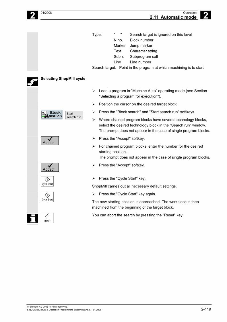
2 01/2008 Operation2.11 Automatic mode
2
© Siemens AG 2008 All rights reserved. SINUMERIK 840D sl Operation/Programming ShopMill (BASsl) - 01/2008 2-119
Type: " " Search target is ignored on this level N no. Block number Marker Jump marker Text Character string Sub-r. Subprogram call Line Line number Search target: Point in the program at which machining is to start
Selecting ShopMill cycle
Load a program in "Machine Auto" operating mode (see Section "Selecting a program for execution").
Position the cursor on the desired target block.
Start search run
Press the "Block search" and "Start search run" softkeys.
Where chained program blocks have several technology blocks, select the desired technology block in the "Search run" window. The prompt does not appear in the case of single program blocks.
Press the "Accept" softkey.
For chained program blocks, enter the number for the desired starting position. The prompt does not appear in the case of single program blocks.
Press the "Accept" softkey.
Cycle Start
Press the "Cycle Start" key.
ShopMill carries out all necessary default settings.
Cycle Start
Press the "Cycle Start" key again.
The new starting position is approached. The workpiece is then machined from the beginning of the target block.
Reset
You can abort the search by pressing the "Reset" key.
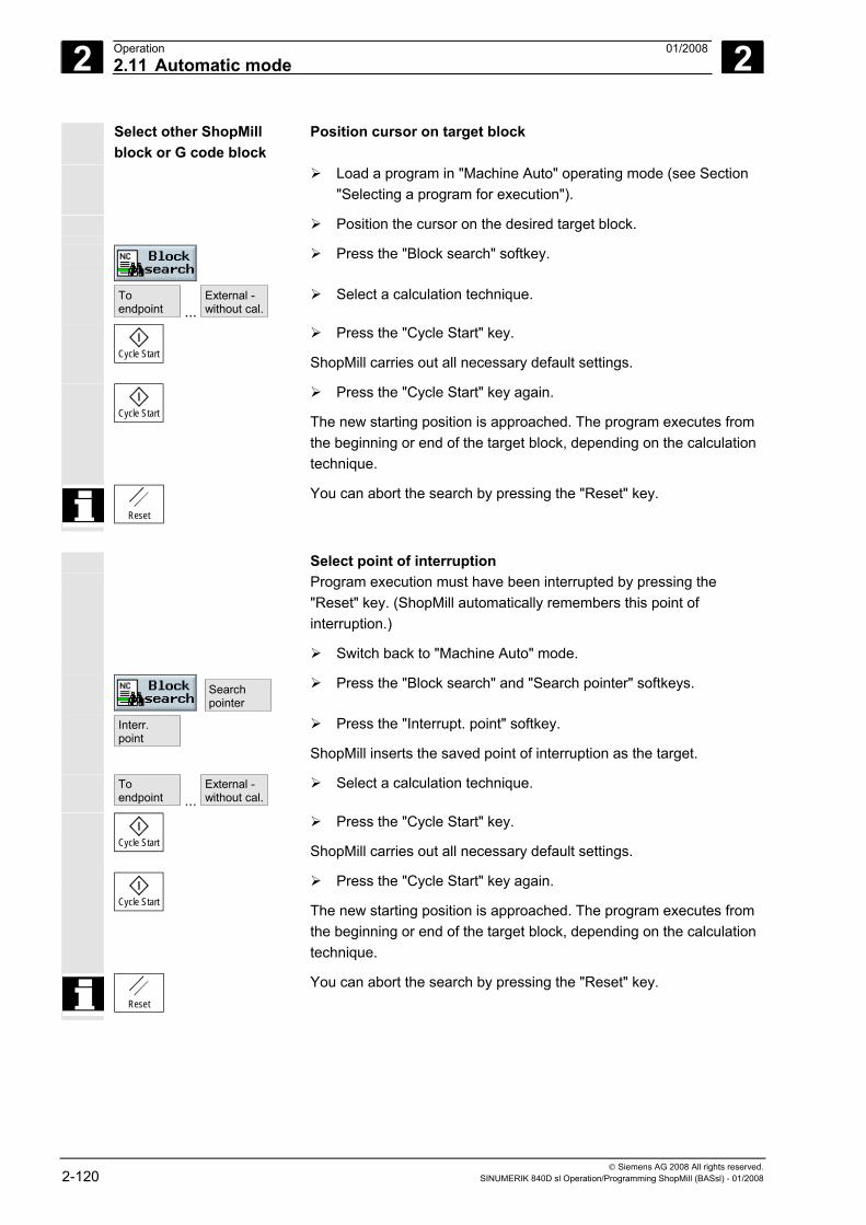
2 Operation 01/2008 2.11 Automatic mode
2
© Siemens AG 2008 All rights reserved. 2-120 SINUMERIK 840D sl Operation/Programming ShopMill (BASsl) - 01/2008
Select other ShopMill block or G code block
Position cursor on target block
Load a program in "Machine Auto" operating mode (see Section "Selecting a program for execution").
Position the cursor on the desired target block.
Press the "Block search" softkey.
To endpoint ...
External -without cal.
Select a calculation technique.
Cycle Start
Press the "Cycle Start" key.
ShopMill carries out all necessary default settings.
Cycle Start
Press the "Cycle Start" key again.
The new starting position is approached. The program executes from the beginning or end of the target block, depending on the calculation technique.
Reset
You can abort the search by pressing the "Reset" key.
Select point of interruption Program execution must have been interrupted by pressing the
"Reset" key. (ShopMill automatically remembers this point of interruption.)
Switch back to "Machine Auto" mode.
Search pointer
Press the "Block search" and "Search pointer" softkeys.
Interr. point
Press the "Interrupt. point" softkey.
ShopMill inserts the saved point of interruption as the target.
To endpoint ...
External -without cal.
Select a calculation technique.
Cycle Start
Press the "Cycle Start" key.
ShopMill carries out all necessary default settings.
Cycle Start
Press the "Cycle Start" key again.
The new starting position is approached. The program executes from the beginning or end of the target block, depending on the calculation technique.
Reset
You can abort the search by pressing the "Reset" key.
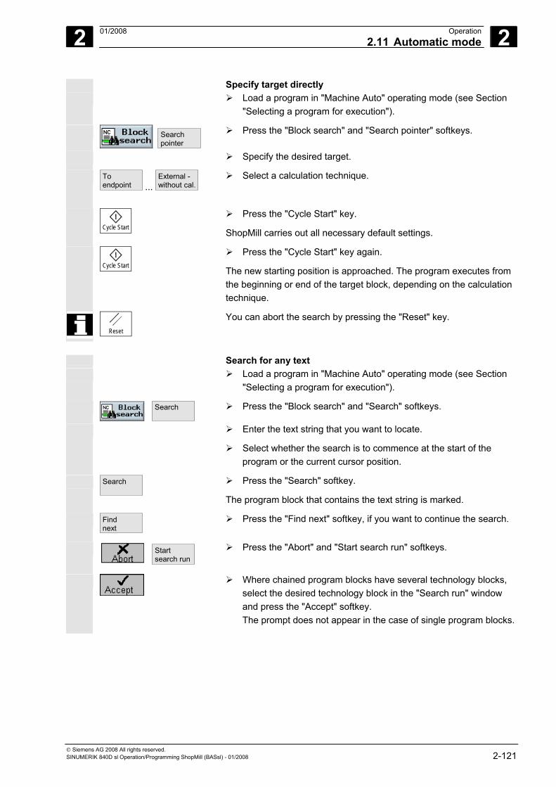
2 01/2008 Operation2.11 Automatic mode
2
© Siemens AG 2008 All rights reserved. SINUMERIK 840D sl Operation/Programming ShopMill (BASsl) - 01/2008 2-121
Specify target directly Load a program in "Machine Auto" operating mode (see Section
"Selecting a program for execution").
Search pointer
Press the "Block search" and "Search pointer" softkeys.
Specify the desired target.
To endpoint ...
External - without cal.
Select a calculation technique.
Cycle Start
Press the "Cycle Start" key.
ShopMill carries out all necessary default settings.
Cycle Start
Press the "Cycle Start" key again.
The new starting position is approached. The program executes from the beginning or end of the target block, depending on the calculation technique.
Reset
You can abort the search by pressing the "Reset" key.
Search for any text Load a program in "Machine Auto" operating mode (see Section
"Selecting a program for execution").
Search
Press the "Block search" and "Search" softkeys.
Enter the text string that you want to locate.
Select whether the search is to commence at the start of the program or the current cursor position.
Search
Press the "Search" softkey.
The program block that contains the text string is marked.
Find next
Press the "Find next" softkey, if you want to continue the search.
Start search run
Press the "Abort" and "Start search run" softkeys.
Where chained program blocks have several technology blocks, select the desired technology block in the "Search run" window and press the "Accept" softkey. The prompt does not appear in the case of single program blocks.
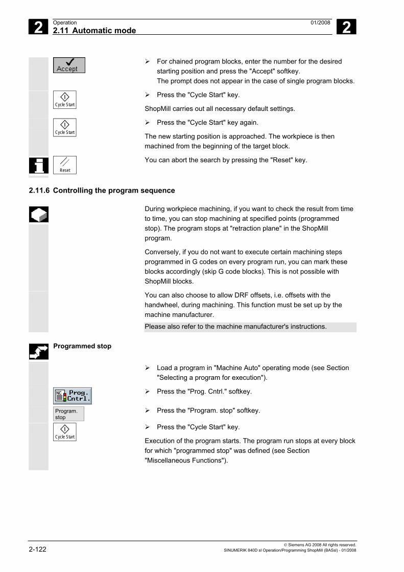
2 Operation 01/2008 2.11 Automatic mode
2
© Siemens AG 2008 All rights reserved. 2-122 SINUMERIK 840D sl Operation/Programming ShopMill (BASsl) - 01/2008
For chained program blocks, enter the number for the desired starting position and press the "Accept" softkey. The prompt does not appear in the case of single program blocks.
Cycle Start
Press the "Cycle Start" key.
ShopMill carries out all necessary default settings.
Cycle Start
Press the "Cycle Start" key again.
The new starting position is approached. The workpiece is then machined from the beginning of the target block.
Reset
You can abort the search by pressing the "Reset" key.
2.11.6 Controlling the program sequence
During workpiece machining, if you want to check the result from time to time, you can stop machining at specified points (programmed stop). The program stops at "retraction plane" in the ShopMill program.
Conversely, if you do not want to execute certain machining steps programmed in G codes on every program run, you can mark these blocks accordingly (skip G code blocks). This is not possible with ShopMill blocks.
You can also choose to allow DRF offsets, i.e. offsets with the handwheel, during machining. This function must be set up by the machine manufacturer.
Please also refer to the machine manufacturer's instructions.
Programmed stop
Load a program in "Machine Auto" operating mode (see Section "Selecting a program for execution").
Press the "Prog. Cntrl." softkey.
Program. stop
Press the "Program. stop" softkey.
Cycle Start
Press the "Cycle Start" key.
Execution of the program starts. The program run stops at every block for which "programmed stop" was defined (see Section "Miscellaneous Functions").
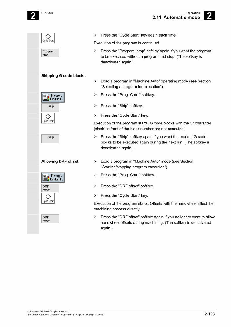
2 01/2008 Operation2.11 Automatic mode
2
© Siemens AG 2008 All rights reserved. SINUMERIK 840D sl Operation/Programming ShopMill (BASsl) - 01/2008 2-123
Cycle Start
Press the "Cycle Start" key again each time.
Execution of the program is continued.
Program. stop
Press the "Program. stop" softkey again if you want the program to be executed without a programmed stop. (The softkey is deactivated again.)
Skipping G code blocks Load a program in "Machine Auto" operating mode (see Section
"Selecting a program for execution").
Press the "Prog. Cntrl." softkey.
Skip
Press the "Skip" softkey.
Cycle Start
Press the "Cycle Start" key.
Execution of the program starts. G code blocks with the "/" character (slash) in front of the block number are not executed.
Skip
Press the "Skip" softkey again if you want the marked G code blocks to be executed again during the next run. (The softkey is deactivated again.)
Allowing DRF offset Load a program in "Machine Auto" mode (see Section
"Starting/stopping program execution").
Press the "Prog. Cntrl." softkey.
DRF offset
Press the "DRF offset" softkey.
Cycle Start
Press the "Cycle Start" key.
Execution of the program starts. Offsets with the handwheel affect the machining process directly.
DRF offset
Press the "DRF offset" softkey again if you no longer want to allow handwheel offsets during machining. (The softkey is deactivated again.)
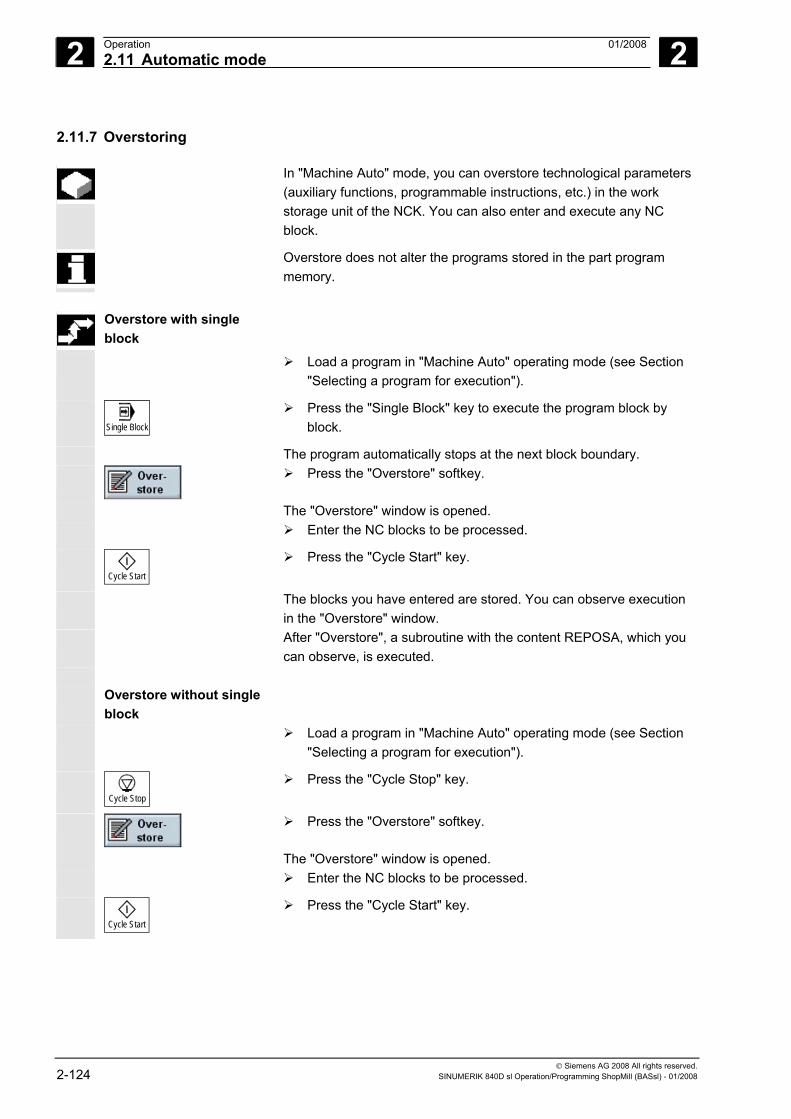
2 Operation 01/2008 2.11 Automatic mode
2
© Siemens AG 2008 All rights reserved. 2-124 SINUMERIK 840D sl Operation/Programming ShopMill (BASsl) - 01/2008
2.11.7 Overstoring
In "Machine Auto" mode, you can overstore technological parameters (auxiliary functions, programmable instructions, etc.) in the work storage unit of the NCK. You can also enter and execute any NC block.
Overstore does not alter the programs stored in the part program memory.
Overstore with single
block
Load a program in "Machine Auto" operating mode (see Section "Selecting a program for execution").
Single Block
Press the "Single Block" key to execute the program block by block.
The program automatically stops at the next block boundary.
Press the "Overstore" softkey.
The "Overstore" window is opened. Enter the NC blocks to be processed.
Cycle Start
Press the "Cycle Start" key.
The blocks you have entered are stored. You can observe execution in the "Overstore" window.
After "Overstore", a subroutine with the content REPOSA, which you can observe, is executed.
Overstore without single
block
Load a program in "Machine Auto" operating mode (see Section "Selecting a program for execution").
Cycle Stop
Press the "Cycle Stop" key.
Press the "Overstore" softkey.
The "Overstore" window is opened. Enter the NC blocks to be processed.
Cycle Start
Press the "Cycle Start" key.
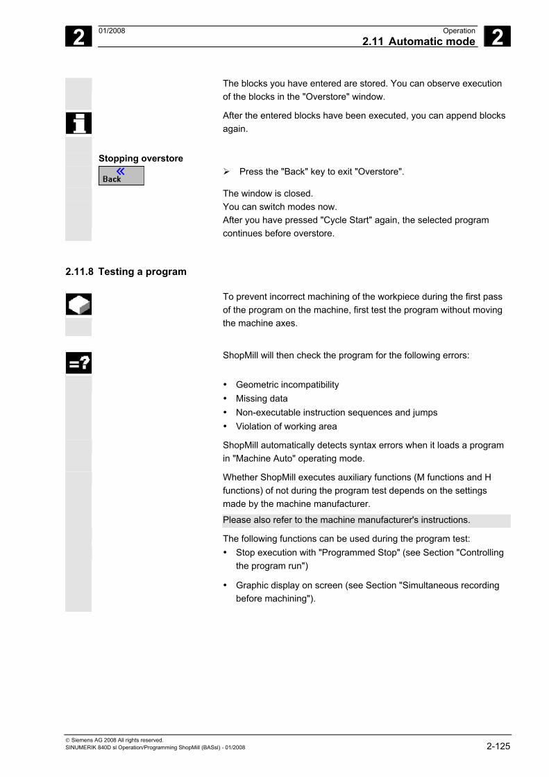
2 01/2008 Operation2.11 Automatic mode
2
© Siemens AG 2008 All rights reserved. SINUMERIK 840D sl Operation/Programming ShopMill (BASsl) - 01/2008 2-125
The blocks you have entered are stored. You can observe execution of the blocks in the "Overstore" window.
After the entered blocks have been executed, you can append blocks again.
Stopping overstore
Press the "Back" key to exit "Overstore".
The window is closed. You can switch modes now. After you have pressed "Cycle Start" again, the selected program
continues before overstore.
2.11.8 Testing a program
To prevent incorrect machining of the workpiece during the first pass of the program on the machine, first test the program without moving the machine axes.
ShopMill will then check the program for the following errors:
• Geometric incompatibility • Missing data • Non-executable instruction sequences and jumps • Violation of working area
ShopMill automatically detects syntax errors when it loads a program in "Machine Auto" operating mode.
Whether ShopMill executes auxiliary functions (M functions and H functions) of not during the program test depends on the settings made by the machine manufacturer.
Please also refer to the machine manufacturer's instructions. The following functions can be used during the program test: • Stop execution with "Programmed Stop" (see Section "Controlling
the program run")
• Graphic display on screen (see Section "Simultaneous recording before machining").
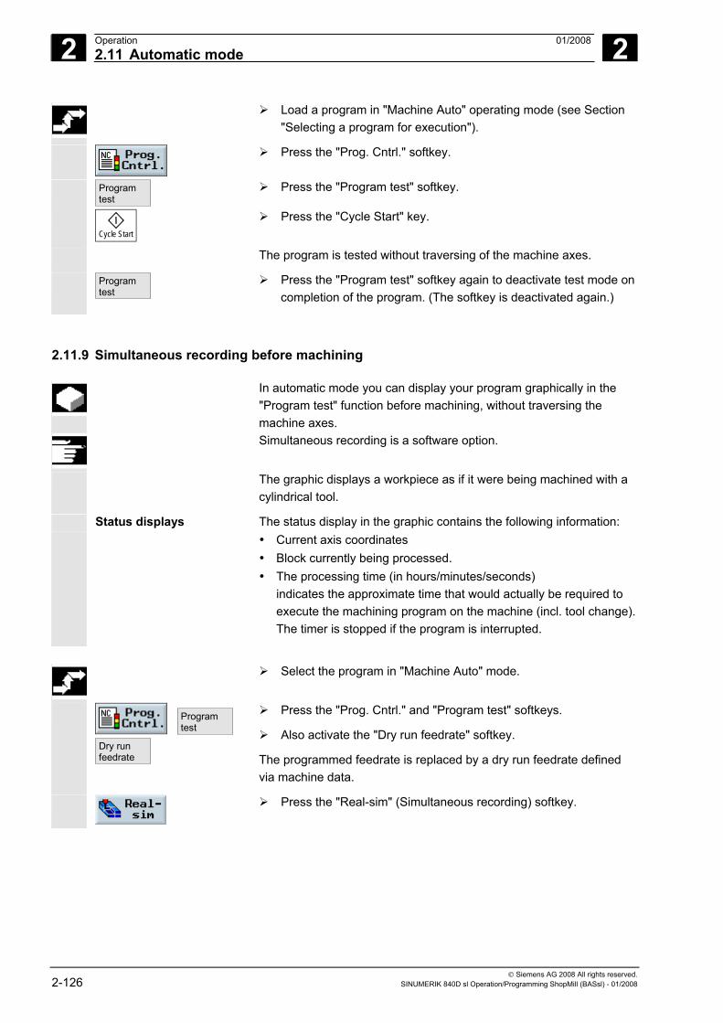
2 Operation 01/2008 2.11 Automatic mode
2
© Siemens AG 2008 All rights reserved. 2-126 SINUMERIK 840D sl Operation/Programming ShopMill (BASsl) - 01/2008
Load a program in "Machine Auto" operating mode (see Section "Selecting a program for execution").
Press the "Prog. Cntrl." softkey.
Programtest
Press the "Program test" softkey.
Cycle Start
Press the "Cycle Start" key.
The program is tested without traversing of the machine axes.
Programtest
Press the "Program test" softkey again to deactivate test mode on completion of the program. (The softkey is deactivated again.)
2.11.9 Simultaneous recording before machining
In automatic mode you can display your program graphically in the "Program test" function before machining, without traversing the machine axes.
Simultaneous recording is a software option.
The graphic displays a workpiece as if it were being machined with a cylindrical tool.
Status displays The status display in the graphic contains the following information: • Current axis coordinates • Block currently being processed. • The processing time (in hours/minutes/seconds)
indicates the approximate time that would actually be required to execute the machining program on the machine (incl. tool change). The timer is stopped if the program is interrupted.
Select the program in "Machine Auto" mode.
Programtest
Dry runfeedrate
Press the "Prog. Cntrl." and "Program test" softkeys.
Also activate the "Dry run feedrate" softkey.
The programmed feedrate is replaced by a dry run feedrate defined via machine data.
Press the "Real-sim" (Simultaneous recording) softkey.
2 01/2008 Operation2.11 Automatic mode
2
© Siemens AG 2008 All rights reserved. SINUMERIK 840D sl Operation/Programming ShopMill (BASsl) - 01/2008 2-127
Cycle Start
Press "Cycle Start" to start the program.
You can still use the program control functions such as "Cycle Stop", "Single block", "Feedrate override", etc.
Programview
Press the "Program view" softkey.
This changes the display from the "Real-sim." graphic to the program view in Automatic mode. Recording of the graphical data continues in the background.
You can return to the graphic display by pressing one of the following softkeys:
Plan view
Press the "Plan view" softkey.
- OR -
Press the "3-Plane View" softkey.
- OR -
Press the "3D Display" softkey (volume model).
You return from the program view to the graphical display. Delete
screen Press the "Delete screen" softkey.
The graphical display of the previous machining is cleared. Recording of the machining operation will however continue.
For more information on the principles and operation, refer to Section "Simulation".
2 Operation 01/2008 2.11 Automatic mode
2
© Siemens AG 2008 All rights reserved. 2-128 SINUMERIK 840D sl Operation/Programming ShopMill (BASsl) - 01/2008
2.11.10 Simultaneous recording during machining
You can track the current machining operation on the machine tool simultaneously by monitoring the graphic display on the control screen.
Requirements Program test and dry run feedrate must not be selected. Simultaneous recording is a software option.
Press the "Real-sim" (Simultaneous recording) softkey and
Cycle Start
start the program with "Cycle Start".
The "simultaneous recording" function can be switched on at any time during machining.
An explanation of the functions available under "Simultaneous recording" can be found in Sections "Simultaneous recording before machining" and "Simulation".
2 01/2008 Operation2.12 Program trial run
2
© Siemens AG 2008 All rights reserved. SINUMERIK 840D sl Operation/Programming ShopMill (BASsl) - 01/2008 2-129
2.12 Program trial run
2.12.1 Single block
If this function is active, execution is interrupted after every block that triggers a function on the machine (calculation blocks are not affected).
Standard setting The following defaults apply: • for drilling, the entire machining procedure and • for pocket milling, the machining of a single plane is combined in a single block.
Select with softkey Singleblock fine
"Single block fine" active When the "Single block fine" function is active, each individual drill infeed and pocket milling motion is executed as a separate block. Also, execution is stopped at the contour after every single contour element.
Select with softkey Singleblock fine
Single block via machine control panel
Single Block
Activate the "Single block" key in "Machine Auto" mode. It will allow you to process a program block by block. If single block is activated, the associated LED on the machine control panel lights up.
If single block execution is active, • The message "Stop: Block completed in single block" is displayed
in the channel operational message line (in interrupt state). • the current block of the program is not executed until you press the
"Cycle Start" key, • Program processing is stopped after one block is executed. • you can start execution of the next block by pressing key "Cycle
Start" again.
Deselecting a single block
Single Block
You can deselect the function by pressing the "Single block" key again.
2 Operation 01/2008 2.12 Program trial run
2
© Siemens AG 2008 All rights reserved. 2-130 SINUMERIK 840D sl Operation/Programming ShopMill (BASsl) - 01/2008
2.12.2 Displaying the current program block
If you want precise information about axis positions and key G functions during a trial run or execution of the program, you can show the basic block display.
You can use the basic block display both in test mode and when
machining the workpiece on the machine. All G code commands that initiate a function on the machine are displayed in the "Basic block" window for the currently active program block: • Absolute axis positions • G functions for the first G group • Other modal G functions • Other programmed addresses • M functions
The basic block display function must be set up by the machine manufacturer.
Please also refer to the machine manufacturer's instructions.
Load a program in "Machine Auto" operating mode (see Section "Selecting a program for execution").
Basic block
Press the "Basic Block" softkey.
Single Block
Press the "Single Block" key if you wish to execute the program block by block.
Cycle Start
Start program execution.
The precise axis positions, modal G functions, etc., are displayed in the "Basic block" window for the currently active program block.
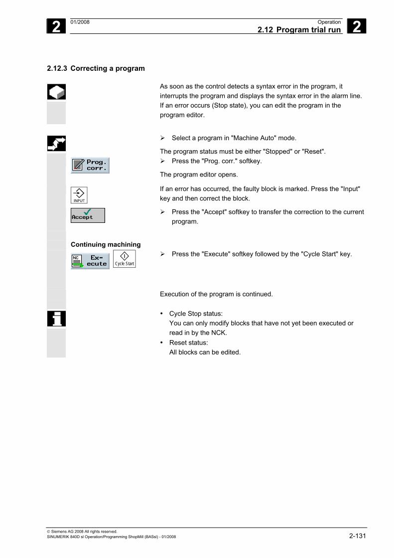
2 01/2008 Operation2.12 Program trial run
2
© Siemens AG 2008 All rights reserved. SINUMERIK 840D sl Operation/Programming ShopMill (BASsl) - 01/2008 2-131
2.12.3 Correcting a program
As soon as the control detects a syntax error in the program, it interrupts the program and displays the syntax error in the alarm line. If an error occurs (Stop state), you can edit the program in the program editor.
Select a program in "Machine Auto" mode.
The program status must be either "Stopped" or "Reset".
Press the "Prog. corr." softkey.
The program editor opens.
If an error has occurred, the faulty block is marked. Press the "Input" key and then correct the block.
Press the "Accept" softkey to transfer the correction to the current program.
Continuing machining
Cycle Start
Press the "Execute" softkey followed by the "Cycle Start" key.
Execution of the program is continued.
• Cycle Stop status: You can only modify blocks that have not yet been executed or
read in by the NCK. • Reset status: All blocks can be edited.
2 Operation 01/2008 2.13 Run times
2
© Siemens AG 2008 All rights reserved. 2-132 SINUMERIK 840D sl Operation/Programming ShopMill (BASsl) - 01/2008
2.13 Run times To provide you with an overview of the most important machine run
times, ShopMill features a status window that displays the following operating times.
Program Measurement of the program run time starts as soon as you press the "Cycle Start" key and stops on NC Stop or NC Reset. If you start a new program, timing starts again from the beginning.
Timing continues if dwell time is active, or during program runs with program test or dry run feedrate. Timing stops with NC Stop or feedrate override = 0.
Loaded By means of a program progress display, you can track what percentage of the called up program has already loaded. The display only appears when a program or subroutine is called via an EXTCALL command or if a program is executed from the hard disk.
Workpiece The current repetition and the programmed number of program repetitions (e.g. Workpiece: 15/100) are displayed in sequence and G-code programs. In work-step programs, the number appears, but only if the number of programmed repetitions N is greater than 1 (see Section "Specifying the Quantity"). After a programmed number of repetitions (100,000), only the current program repetition is displayed due to lack of space (e.g. workpiece: 15). If no information is yet available about the current program repetition, only two dashes are displayed (e.g. Workpiece: - -/100). After the start of a program, the counter shows 0 for the current repetition.
For counting workpieces, you specify the actual and desired numbers of workpieces as presettings (see Section "Assigning the Quantity").
Time The current time is displayed here.
Date Today's date is displayed.
Machine The machine run time displays how much time has elapsed since the control was last switched on.
Machining The machining time displays the total run time of all programs executed since the control was last switched on.
2 01/2008 Operation2.13 Run times
2
© Siemens AG 2008 All rights reserved. SINUMERIK 840D sl Operation/Programming ShopMill (BASsl) - 01/2008 2-133
Machine statistic The system calculates the actual machine utilization from the timed machining time and the current machine run time. The ratio of machining time to machine run time is displayed as a percentage.
A setting in the machine data determines which run times are displayed.
Please also refer to the machine manufacturer's instructions.
Jog Auto
Select "Machine Manual" or "Machine Auto" mode.
Run times
Press the "Run times" softkey.
The T,F,S display window turns into the "Run times" window. Pressing the "Run times" softkey again, takes you back to the T,F,S display window.
2 Operation 01/2008 2.14 Settings for automatic mode
2
© Siemens AG 2008 All rights reserved. 2-134 SINUMERIK 840D sl Operation/Programming ShopMill (BASsl) - 01/2008
2.14 Settings for automatic mode For automatic mode, configure the pre-settings for the following
functions:
• Program sequence under Automatic For graphical display of a program, the feedrate of the test-run can be specified.
• Workpiece counter For counting workpieces in G-code programs, counters are available, which display the number of needed workpieces as well as the total number of workpieces produced.
2.14.1 Specifying the dry run feedrate
Before machining a workpiece, test the program without moving the machine axes. For early detection of programming errors, the parallel drawing function is available to you. For this, you can use your own preset test-run feedrate (see Section "Parallel drawing before machining the workpiece").
The feedrate can be changed while the operation is running.
Auto
Switch to "Machine Auto" mode in the expanded horizontal softkey bar.
Press the "ShopM. sett." softkey.
In "Test-run feedrate," enter the desired test-run speed.
2 01/2008 Operation 2
© Siemens AG 2008 All rights reserved. SINUMERIK 840D sl Operation/Programming ShopMill (BASsl) - 01/2008 2-135
2.14.2 Parameterizing the workpiece counter
With the aid of the "ShopMill Settings", you can control the counter activation and the time of the zeroing. The display of the needed and currently machined workpieces is displayed in the machine run-time window (see Section "Run-times").
Number of workpieces
Auto
Switch to "Machine Auto" mode in the expanded horizontal softkey bar.
Press the "ShopM. Sett." softkey.
Enter the number of workpieces needed in the "Desired workpieces" field.
The number of workpieces finished since the program started is displayed in the "Actual workpieces" field. After the defined number of workpieces is reached, the current workpieces display is automatically reset to zero.
The choice of counter depends on the machine data setting. Please also refer to the machine manufacturer's instructions.
The desired and actual numbers for the workpiece counter can also be changed during program execution.
2 Operation 01/2008 2.15 Tools and tool offsets
2
© Siemens AG 2008 All rights reserved. 2-136 SINUMERIK 840D sl Operation/Programming ShopMill (BASsl) - 01/2008
2.15 Tools and tool offsets You can manage tools with ShopMill. The following lists are available
to you for this function • Tool list • Tool wear list • Magazine list
Enter the tools, their offset data and wear monitoring data in the tool list or tool wear list. You will be able to identify in the magazine list which magazine locations are disabled or not.
Depending on individual requirements, a tool list might consist of the following:
• A tool changer comprising − a spindle without dual gripper − or a spindle with dual gripper
• at least one tool magazine • and tools that are not assigned to any tool magazine.
For details of the functionality of your tool management system, please refer to the machine manufacturer's instructions. The different lists can be adapted by the machine manufacturer, if necessary.
Tool list The tool list displays all tools and their offset data stored as a tool data
block in the NCK, irrespective of whether or not they are assigned to a magazine location. The tool list offers you all commonly used tools. You can assign geometric and technological tool data to tool types. Various different examples of each tool might exist to which you can assign the various offset data of the tool being used.
Depending on the tool type used, different tool offset data will be
required.
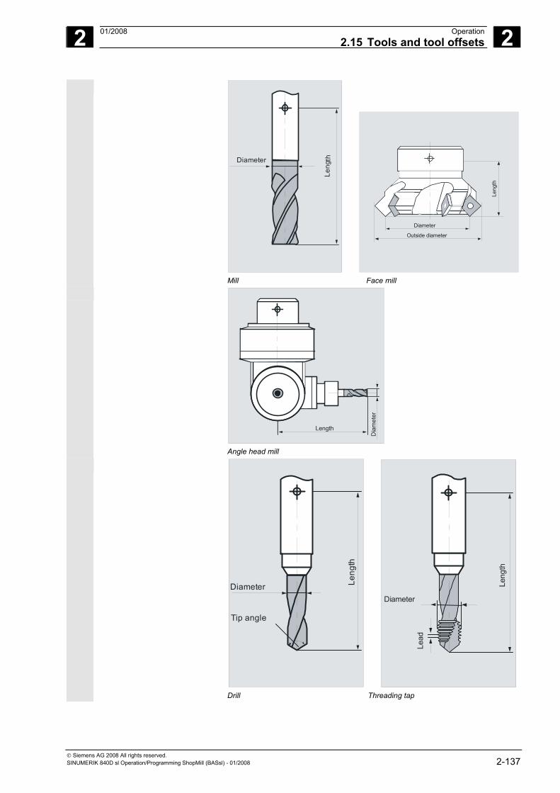
2 01/2008 Operation2.15 Tools and tool offsets
2
© Siemens AG 2008 All rights reserved. SINUMERIK 840D sl Operation/Programming ShopMill (BASsl) - 01/2008 2-137
Leng
th
Diameter
Leng
th
Diameter
Outside diameter
Mill Face mill
Dia
met
er
Length
Angle head mill
Leng
th
Diameter
Tip angle
Leng
th
Diameter
Lead
Drill Threading tap
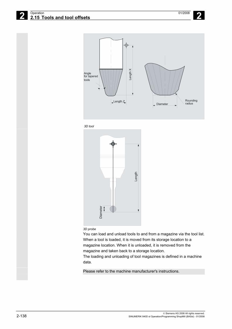
2 Operation 01/2008 2.15 Tools and tool offsets
2
© Siemens AG 2008 All rights reserved. 2-138 SINUMERIK 840D sl Operation/Programming ShopMill (BASsl) - 01/2008
DiameterRoundingradius
Leng
th X
Length Z
Anglefor taperedtools
3D tool
Leng
th
Dia
met
er
3D probe
You can load and unload tools to and from a magazine via the tool list. When a tool is loaded, it is moved from its storage location to a magazine location. When it is unloaded, it is removed from the magazine and taken back to a storage location. The loading and unloading of tool magazines is defined in a machine data.
Please refer to the machine manufacturer's instructions.
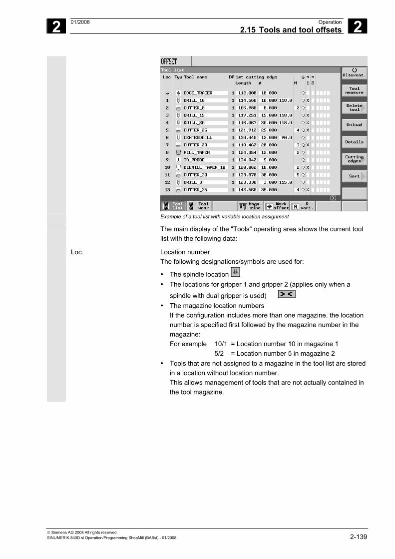
2 01/2008 Operation2.15 Tools and tool offsets
2
© Siemens AG 2008 All rights reserved. SINUMERIK 840D sl Operation/Programming ShopMill (BASsl) - 01/2008 2-139
Example of a tool list with variable location assignment
The main display of the "Tools" operating area shows the current tool list with the following data:
Loc. Location number The following designations/symbols are used for:
• The spindle location • The locations for gripper 1 and gripper 2 (applies only when a
spindle with dual gripper is used) • The magazine location numbers
If the configuration includes more than one magazine, the location number is specified first followed by the magazine number in the magazine:
For example 10/1 = Location number 10 in magazine 1 5/2 = Location number 5 in magazine 2 • Tools that are not assigned to a magazine in the tool list are stored
in a location without location number. This allows management of tools that are not actually contained in the tool magazine.
2 Operation 01/2008 2.15 Tools and tool offsets
2
© Siemens AG 2008 All rights reserved. 2-140 SINUMERIK 840D sl Operation/Programming ShopMill (BASsl) - 01/2008
Type Tool type Depending on the tool type (represented by a symbol), only certain tool offset data are enabled.
Tool name A tool is identified by its name and duplo number. You can enter the name as text or a number (see Section "Changing tool names").
DP Duplo number of twin tool (replacement tool) Tool offset data (D No.) edge Tool offset data for the selected cutting edge of a tool (D No.)
Length Tool length You can determine this value using the "Measure tool" function (see Section "Measuring the tool manually"). If the tool is measured externally, you can enter the value here.
Radius or ∅ Radius or diameter of the tool You can also enter the diameter for milling cutters and drills. A machine data code is used to switch from radius to diameter specification.
Angle Angle of tool tip on a drill. If you want to insert a drill down to the shank, and not just to the tool tip, the control also takes the angle of the drill tip into account.
H The "H" column is displayed only if ISO dialects are set up. Every H number of an ISO dialect program must be assigned to a tool offset data record.
N Number of teeth for a milling cutter Pitch Thread lead of a tap in mm/rev, in/rev, turns/" or MODUL if the inch
system is set up on the machine. Tool-specific functions
Direction of spindle rotation
Coolant supply 1 and 2 can be activated/deactivated (e.g. internal and external cooling)
Tool-spec. fct 1...4 Other tool-specific functions such as additional coolant supply, monitoring functions for speed, tool breakage, etc.
Please also refer to the machine manufacturer's instructions.
The "Details" softkey displays the additional parameters "Rounding radius" or "Angle" for 3D tapered milling tools. For the facing tool, an additional outside radius and tool angle, and for angle head cutter, additional lengths and wear lengths are displayed under "Details.
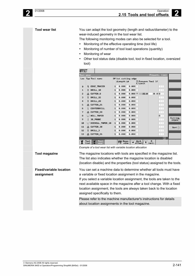
2 01/2008 Operation2.15 Tools and tool offsets
2
© Siemens AG 2008 All rights reserved. SINUMERIK 840D sl Operation/Programming ShopMill (BASsl) - 01/2008 2-141
Tool wear list
You can adapt the tool geometry (length and radius/diameter) to the wear-induced geometry in the tool wear list. The following monitoring modes can also be selected for a tool. • Monitoring of the effective operating time (tool life) • Monitoring of number of tool load operations (quantity) • Monitoring of wear • Other tool status data (disable tool, tool in fixed location, oversized
tool)
Example of a tool wear list with variable location allocation
Tool magazine The magazine locations with tools are specified in the magazine list. The list also indicates whether the magazine location is disabled (location disable) and the properties (tool status) assigned to the tools.
Fixed/variable location assignment
You can set a machine data to determine whether all tools must have a variable or fixed location assignment in the magazine. If you select a variable location assignment, the tools are taken to the next available space in the magazine after a tool change. With a fixed location assignment, the tools are always taken back to the location assigned specifically to them.
Please refer to the machine manufacturer's instructions for details about location assignments in the tool magazine.
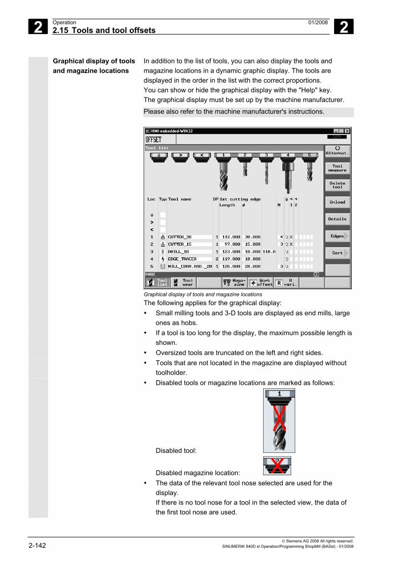
2 Operation 01/2008 2.15 Tools and tool offsets
2
© Siemens AG 2008 All rights reserved. 2-142 SINUMERIK 840D sl Operation/Programming ShopMill (BASsl) - 01/2008
Graphical display of tools and magazine locations
In addition to the list of tools, you can also display the tools and magazine locations in a dynamic graphic display. The tools are displayed in the order in the list with the correct proportions. You can show or hide the graphical display with the "Help" key. The graphical display must be set up by the machine manufacturer.
Please also refer to the machine manufacturer's instructions.
Graphical display of tools and magazine locations
The following applies for the graphical display: • Small milling tools and 3-D tools are displayed as end mills, large
ones as hobs. • If a tool is too long for the display, the maximum possible length is
shown. • Oversized tools are truncated on the left and right sides. • Tools that are not located in the magazine are displayed without
toolholder. • Disabled tools or magazine locations are marked as follows:
Disabled tool:
Disabled magazine location: • The data of the relevant tool nose selected are used for the
display. If there is no tool nose for a tool in the selected view, the data of the first tool nose are used.
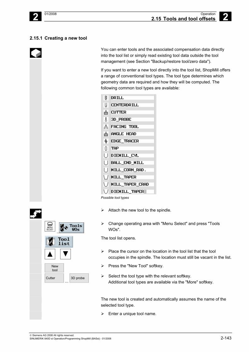
2 01/2008 Operation2.15 Tools and tool offsets
2
© Siemens AG 2008 All rights reserved. SINUMERIK 840D sl Operation/Programming ShopMill (BASsl) - 01/2008 2-143
2.15.1 Creating a new tool
You can enter tools and the associated compensation data directly into the tool list or simply read existing tool data outside the tool management (see Section "Backup/restore tool/zero data").
If you want to enter a new tool directly into the tool list, ShopMill offers a range of conventional tool types. The tool type determines which geometry data are required and how they will be computed. The following common tool types are available:
Possible tool types
Attach the new tool to the spindle.
..
Change operating area with "Menu Select" and press "Tools WOs".
The tool list opens.
Place the cursor on the location in the tool list that the tool occupies in the spindle. The location must still be vacant in the list.
New tool
Press the "New Tool" softkey.
Cutter ...
3D probe
Select the tool type with the relevant softkey. Additional tool types are available via the "More" softkey.
The new tool is created and automatically assumes the name of the selected tool type.
Enter a unique tool name.
2 Operation 01/2008 2.15 Tools and tool offsets
2
© Siemens AG 2008 All rights reserved. 2-144 SINUMERIK 840D sl Operation/Programming ShopMill (BASsl) - 01/2008
Enter the offset data of the tool.
In the case of facing tools, angle head cutters, and 3D tools, you must define parameters in addition to the geometry data in the tool list.
Details
Press the "Details" softkey and enter the additional parameters. The "Details" softkey is only active when a tool is selected for which additional information is required.
Additional parameters of the angle head cutter
For the angle head cutter, use machine data to activate the displaying of additional parameters on the basic length and the tool orientation.
Please also refer to the machine manufacturer's instructions.
The axes descriptions in the detailed screen of the angle head cutter are in relation to G17 as currently set plane.
Name Additional parameters Angle head mill Geometry length (length X, length Y, length Z)
Wear (Δlength X, Δlength Y, Δlength Z) Basic length (length X, length Y, length Z) Tool direction (+X, -X, +Y, -Y, +Z, -Z and/or vector X, vector Y, vector Z)
Facing tool Outside diameter, tool angle
3D tools
Type Name Additional parameters 110 Cylindrical die mill - 111 Ball end mill Smoothing radius 121 End mill with corner rounding Smoothing radius 155 Bevel cutter Angle for conical tools 156 Bevel cutter with corner rounding Rounding radius, angle of conic. tools 157 Tapered die-sinking cutter Angle for conical tools .
2 01/2008 Operation2.15 Tools and tool offsets
2
© Siemens AG 2008 All rights reserved. SINUMERIK 840D sl Operation/Programming ShopMill (BASsl) - 01/2008 2-145
2.15.2 Creating multiple cutting edges for each tool
In the case of tools with more than one cutting edge, a separate set of offset data is assigned to each cutting edge. You can set up a total of 9 edges for each tool.
There must be no gaps between the edges, i.e. if 3 edges are required for a tool, these must be edges 1 to 3.
In the case of ISO programs (e.g. ISO dialect 1) you must specify an
H number. This corresponds to a particular tool offset set.
Follow the instructions given above to set up tools with more than one
edge in the tool list and enter the offset data for the 1st edge.
Cuttingedges >
New cuttingedge
Then select the "Cutting edges" and "New cutting edge" softkeys.
Instead of the input fields for the first cutting edge, the offset data input fields for the second cutting edge are displayed.
Enter the offset data for the second cutting edge.
Repeat this process if you wish to create more tool edge offset data.
Delete cut-ting edge
Select the "Delete cutting edge" softkey if you want to delete the tool edge offset data for an edge. You can only delete the data for the edge with the highest edge number.
D No. +
D No. -
By selecting softkey "D No. +" or "D No. –", you can display the offset data for the edge with the next highest or next lowest edge number respectively.
2 Operation 01/2008 2.15 Tools and tool offsets
2
© Siemens AG 2008 All rights reserved. 2-146 SINUMERIK 840D sl Operation/Programming ShopMill (BASsl) - 01/2008
2.15.3 Changing a tool name
A tool that has just been created in the tool list is automatically assigned the name of the selected tool group. You can change this name as often as you want to • a tool name, e.g. "Facing tool_120mm", or • a tool number, e.g. "1". The tool name must not exceed 17 characters in length. You can use letters, digits, the underscore symbol (_), periods (".") and slashes ("/").
2.15.4 Creating a replacement tool
A replacement tool is one that can be employed to perform the same machining operation as a tool that already exists (e.g. as a replacement after tool breakage).
When you create a tool as a replacement, you must give it the same name as an existing comparable tool.
Confirm the name with the "Input" key. The duplo number of the replacement tool will automatically be incremented by 1.
The order in which replacement tools are attached to the spindle is determined by duplo number DP.
2.15.5 Manual tools
Manual tools are tools which are required during machining, but are only available in the tool list but not in the tool-holding magazine. These tools must be attached/detached manually to/from the spindle.
The "manual tool" function must be set up by the machine manufacturer.
Please also refer to the machine manufacturer's instructions.
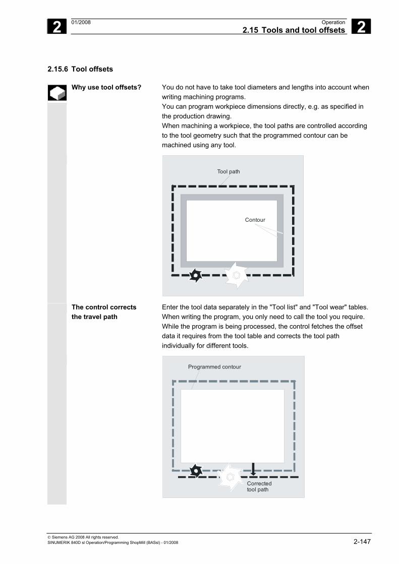
2 01/2008 Operation2.15 Tools and tool offsets
2
© Siemens AG 2008 All rights reserved. SINUMERIK 840D sl Operation/Programming ShopMill (BASsl) - 01/2008 2-147
2.15.6 Tool offsets
Why use tool offsets? You do not have to take tool diameters and lengths into account when writing machining programs. You can program workpiece dimensions directly, e.g. as specified in the production drawing. When machining a workpiece, the tool paths are controlled according to the tool geometry such that the programmed contour can be machined using any tool.
Tool path
Contour
The control corrects the travel path
Enter the tool data separately in the "Tool list" and "Tool wear" tables.When writing the program, you only need to call the tool you require. While the program is being processed, the control fetches the offset data it requires from the tool table and corrects the tool path individually for different tools.
Correctedtool path
Programmed contour
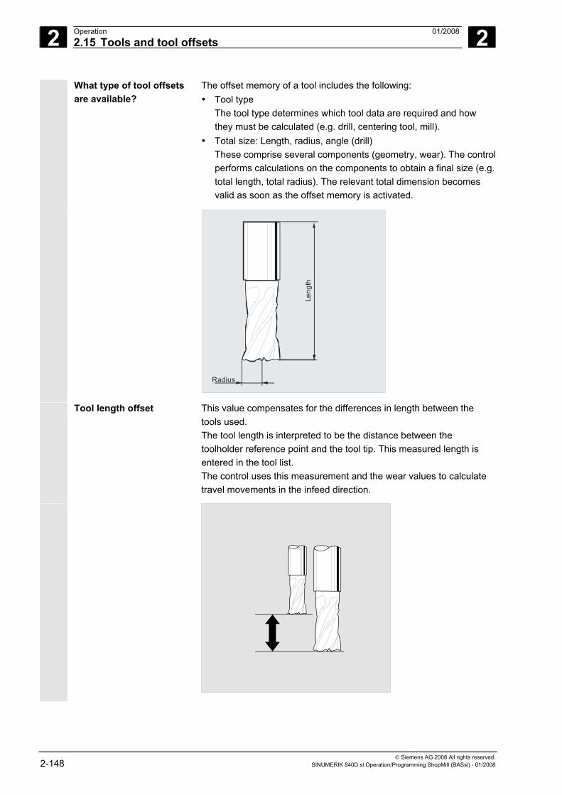
2 Operation 01/2008 2.15 Tools and tool offsets
2
© Siemens AG 2008 All rights reserved. 2-148 SINUMERIK 840D sl Operation/Programming ShopMill (BASsl) - 01/2008
What type of tool offsets are available?
The offset memory of a tool includes the following: • Tool type
The tool type determines which tool data are required and how they must be calculated (e.g. drill, centering tool, mill).
• Total size: Length, radius, angle (drill) These comprise several components (geometry, wear). The control performs calculations on the components to obtain a final size (e.g. total length, total radius). The relevant total dimension becomes valid as soon as the offset memory is activated.
Radius
Leng
th
Tool length offset
This value compensates for the differences in length between the tools used. The tool length is interpreted to be the distance between the toolholder reference point and the tool tip. This measured length is entered in the tool list. The control uses this measurement and the wear values to calculate travel movements in the infeed direction.
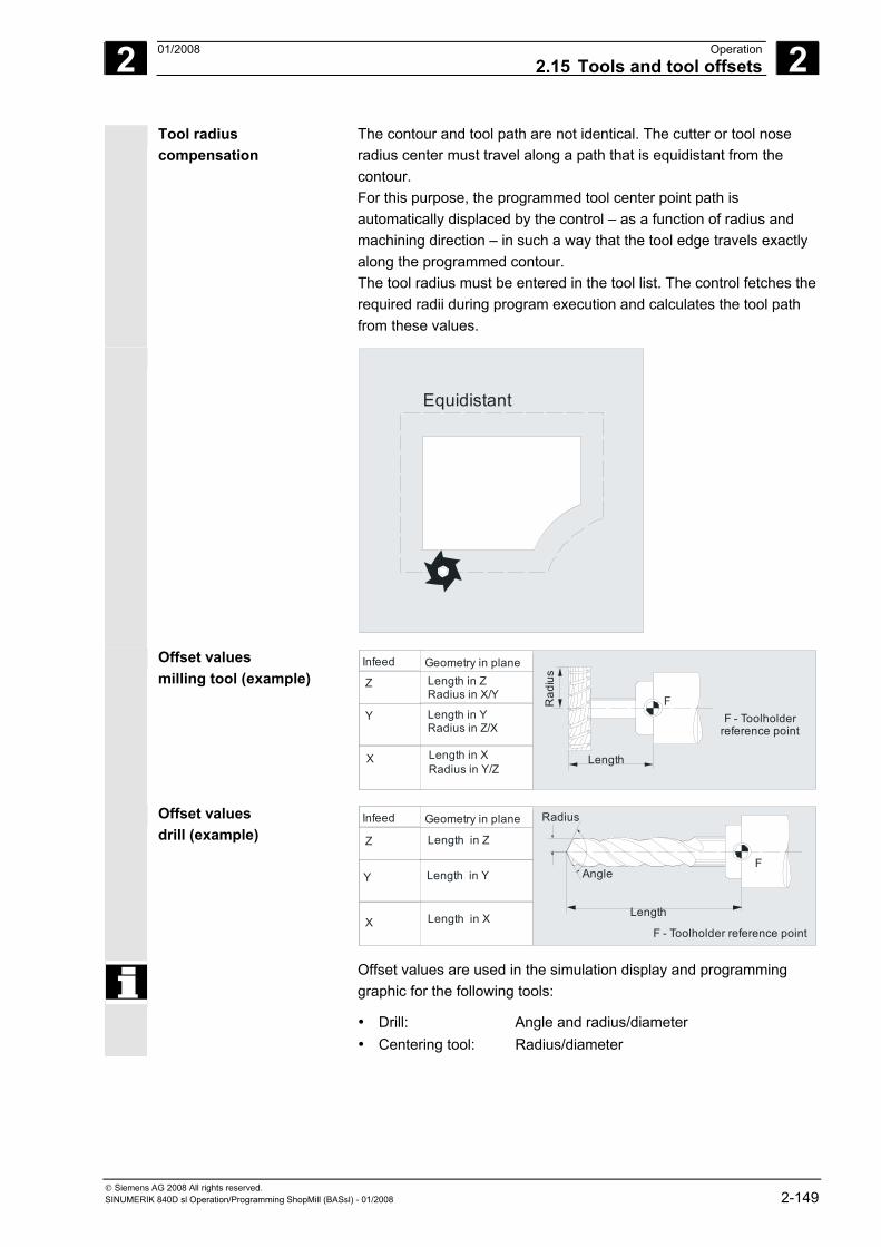
2 01/2008 Operation2.15 Tools and tool offsets
2
© Siemens AG 2008 All rights reserved. SINUMERIK 840D sl Operation/Programming ShopMill (BASsl) - 01/2008 2-149
Tool radius compensation
The contour and tool path are not identical. The cutter or tool nose radius center must travel along a path that is equidistant from the contour. For this purpose, the programmed tool center point path is automatically displaced by the control – as a function of radius and machining direction – in such a way that the tool edge travels exactly along the programmed contour. The tool radius must be entered in the tool list. The control fetches the required radii during program execution and calculates the tool path from these values.
Equidistant
Offset values milling tool (example)
FZ Length in Z
Radius in X/Y
Y Length in YRadius in Z/X
Length in XRadius in Y/Z
X
F - Toolholderreference point
Rad
ius
Length
Infeed Geometry in plane
Offset values drill (example) Z Length in Z
Y Length in Y
Length in XXF - Toolholder reference point
Infeed Geometry in plane
F
Length
F Angle
Radius
Offset values are used in the simulation display and programming graphic for the following tools:
• Drill: Angle and radius/diameter • Centering tool: Radius/diameter
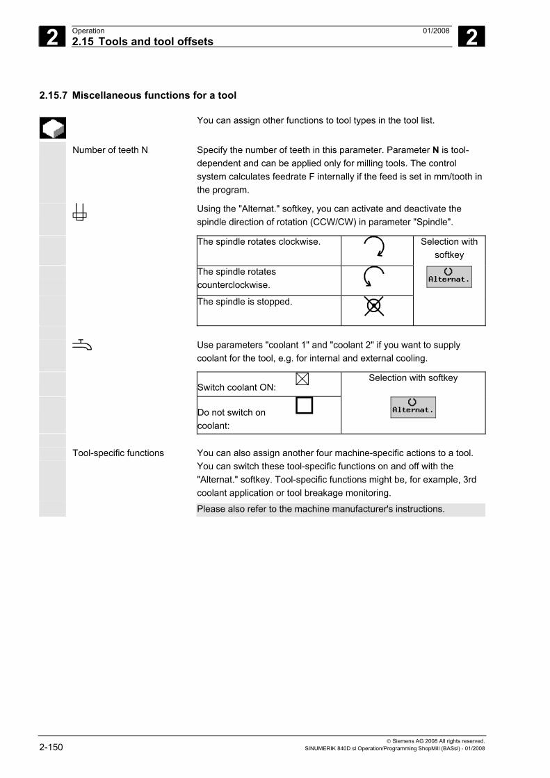
2 Operation 01/2008 2.15 Tools and tool offsets
2
© Siemens AG 2008 All rights reserved. 2-150 SINUMERIK 840D sl Operation/Programming ShopMill (BASsl) - 01/2008
2.15.7 Miscellaneous functions for a tool
You can assign other functions to tool types in the tool list.
Number of teeth N Specify the number of teeth in this parameter. Parameter N is tool-dependent and can be applied only for milling tools. The control system calculates feedrate F internally if the feed is set in mm/tooth in the program.
Using the "Alternat." softkey, you can activate and deactivate the spindle direction of rotation (CCW/CW) in parameter "Spindle".
The spindle rotates clockwise.
Selection with softkey
The spindle rotates counterclockwise.
The spindle is stopped.
Use parameters "coolant 1" and "coolant 2" if you want to supply coolant for the tool, e.g. for internal and external cooling.
Switch coolant ON:
Selection with softkey
Do not switch on coolant:
Tool-specific functions You can also assign another four machine-specific actions to a tool.
You can switch these tool-specific functions on and off with the "Alternat." softkey. Tool-specific functions might be, for example, 3rd coolant application or tool breakage monitoring.
Please also refer to the machine manufacturer's instructions.
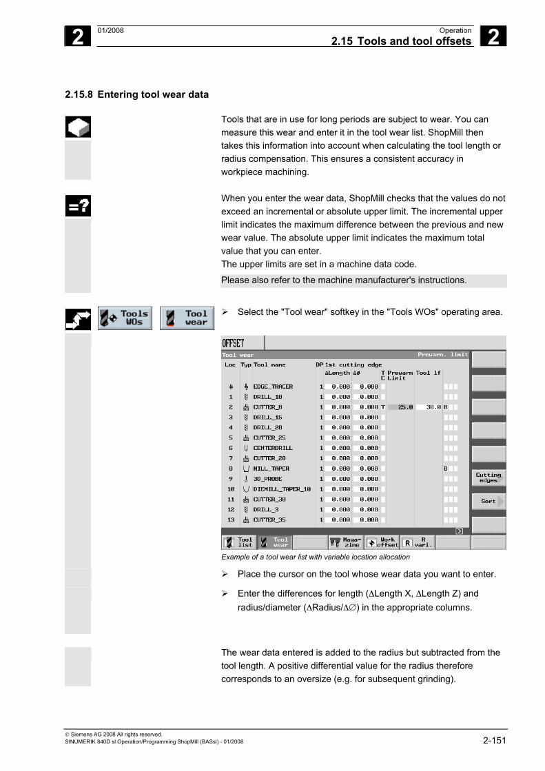
2 01/2008 Operation2.15 Tools and tool offsets
2
© Siemens AG 2008 All rights reserved. SINUMERIK 840D sl Operation/Programming ShopMill (BASsl) - 01/2008 2-151
2.15.8 Entering tool wear data
Tools that are in use for long periods are subject to wear. You can measure this wear and enter it in the tool wear list. ShopMill then takes this information into account when calculating the tool length or radius compensation. This ensures a consistent accuracy in workpiece machining.
When you enter the wear data, ShopMill checks that the values do not
exceed an incremental or absolute upper limit. The incremental upper limit indicates the maximum difference between the previous and new wear value. The absolute upper limit indicates the maximum total value that you can enter. The upper limits are set in a machine data code.
Please also refer to the machine manufacturer's instructions.
Select the "Tool wear" softkey in the "Tools WOs" operating area.
Example of a tool wear list with variable location allocation
Place the cursor on the tool whose wear data you want to enter.
Enter the differences for length (ΔLength X, ΔLength Z) and radius/diameter (ΔRadius/Δ∅) in the appropriate columns.
The wear data entered is added to the radius but subtracted from the
tool length. A positive differential value for the radius therefore corresponds to an oversize (e.g. for subsequent grinding).
2 Operation 01/2008 2.15 Tools and tool offsets
2
© Siemens AG 2008 All rights reserved. 2-152 SINUMERIK 840D sl Operation/Programming ShopMill (BASsl) - 01/2008
2.15.9 Activating tool monitoring
ShopMill allows you to monitor the tool life of the tools automatically to ensure constant machining quality.
You can also disable tools that you no longer want to use, identify them as oversize or assign them permanently to a magazine location.
Tool monitoring can be activated via a machine data code.
Please also refer to the machine manufacturer's instructions.
Tool life (T) With the tool life T (Time), the service life for a tool with machining feedrate is monitored in minutes. When the remaining tool life is = 0, the tool is set to "disabled". The tool is not put into operation on the next tool change. If a replacement tool is available, it is inserted in its place. Tool life is monitored on the basis of the selected tool cutting edge.
Count (C) With the count C, on the other hand, the number of times a tool is attached to a spindle is counted. The tool is also disabled in this case, when the remainder reaches "0".
Wear (W) With wear W, the greatest value in the wear parameters Δ Length X, Δ Length Z, or Δ Radius or Δ ∅ in the wear list is monitored. Here, too, the tool is disabled if one of the wear parameters reaches the value forwear W.
The wear monitoring function must be set up by the machine manufacturer.
Please also refer to the machine manufacturer's instructions. Pre-warning limit The pre-warning limit specifies a tool life, workpiece count or wear at
which the first warning is displayed. The value for output of a warning due to the wear stage reached is calculated from the difference between the maximum wear and the warning limit entered.
Disabled (G) Individual tools can also be disabled manually if you no longer want to use them for workpiece machining.
Oversize (U) In the case of oversize tools, neighboring magazine locations (left and right adjacent location) are only reserved alternately, i.e. you can only insert the next tool in the next magazine location but one. (This can also contain an oversize tool.)
Fixed-location-coded (F) You can assign tools to a fixed location, i.e., the tool can only be used in its present magazine location. After machining, the tool always returns to its old magazine location.
2 01/2008 Operation2.15 Tools and tool offsets
2
© Siemens AG 2008 All rights reserved. SINUMERIK 840D sl Operation/Programming ShopMill (BASsl) - 01/2008 2-153
Monitoring tool use
Select the "Tool wear" softkey in the "Tools WOs" operating area.
Position the cursor on the tool that you want to monitor.
In the column "T/C" select the parameter that you wish to monitor (T = Tool life, C = Count, W = Wear).
Enter a pre-warning limit for the tool life, count, or wear.
Enter the scheduled service life for the tool, the scheduled number of workpieces to be machined or the maximum permissible wear.
The tool is disabled when the tool life, count, or wear is reached.
Entering tool statuses
Select the "Tool wear" softkey in the "Tools WOs" operating area.
Place the cursor on a tool.
Select the option "G" in the first field of the last column if you want to disable the tool for machining.
-or-
Select the option "U" in the second field of the last column if you want to mark the tool as oversize.
-or-
Select the option "P" in the third field of the last column if you want assign the tool to a fixed magazine location.
The tool properties you have set become active immediately.
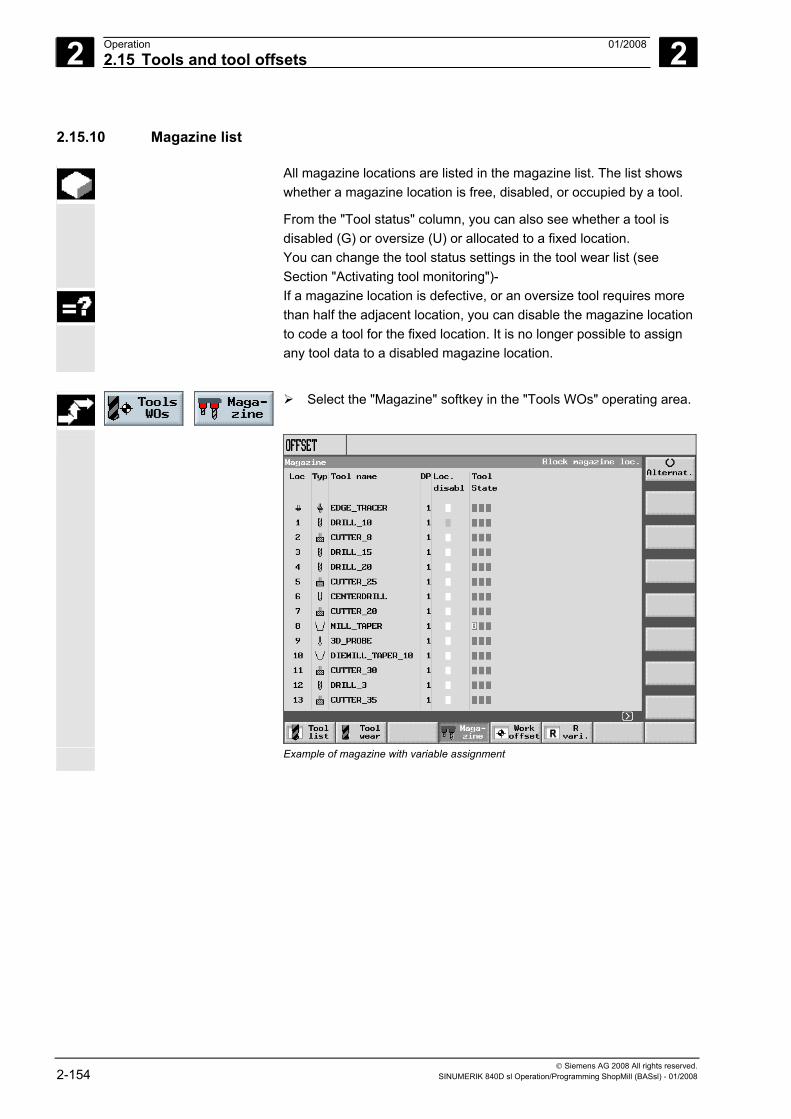
2 Operation 01/2008 2.15 Tools and tool offsets
2
© Siemens AG 2008 All rights reserved. 2-154 SINUMERIK 840D sl Operation/Programming ShopMill (BASsl) - 01/2008
2.15.10 Magazine list
All magazine locations are listed in the magazine list. The list shows whether a magazine location is free, disabled, or occupied by a tool.
From the "Tool status" column, you can also see whether a tool is disabled (G) or oversize (U) or allocated to a fixed location. You can change the tool status settings in the tool wear list (see Section "Activating tool monitoring")-
If a magazine location is defective, or an oversize tool requires more than half the adjacent location, you can disable the magazine location to code a tool for the fixed location. It is no longer possible to assign any tool data to a disabled magazine location.
Select the "Magazine" softkey in the "Tools WOs" operating area.
Example of magazine with variable assignment
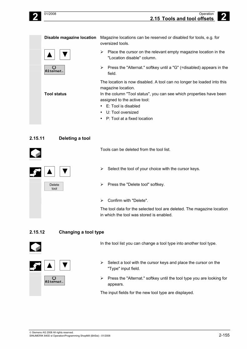
2 01/2008 Operation2.15 Tools and tool offsets
2
© Siemens AG 2008 All rights reserved. SINUMERIK 840D sl Operation/Programming ShopMill (BASsl) - 01/2008 2-155
Disable magazine location Magazine locations can be reserved or disabled for tools, e.g. for oversized tools.
Place the cursor on the relevant empty magazine location in the "Location disable" column.
Press the "Alternat." softkey until a "G" (=disabled) appears in the field.
The location is now disabled. A tool can no longer be loaded into this magazine location.
Tool status In the column "Tool status", you can see which properties have been assigned to the active tool: • E: Tool is disabled • U: Tool oversized • P: Tool at a fixed location
2.15.11 Deleting a tool
Tools can be deleted from the tool list.
Select the tool of your choice with the cursor keys.
Delete tool
Press the "Delete tool" softkey.
Confirm with "Delete".
The tool data for the selected tool are deleted. The magazine location in which the tool was stored is enabled.
2.15.12 Changing a tool type
In the tool list you can change a tool type into another tool type.
Select a tool with the cursor keys and place the cursor on the "Type" input field.
Press the "Alternat." softkey until the tool type you are looking for appears.
The input fields for the new tool type are displayed.
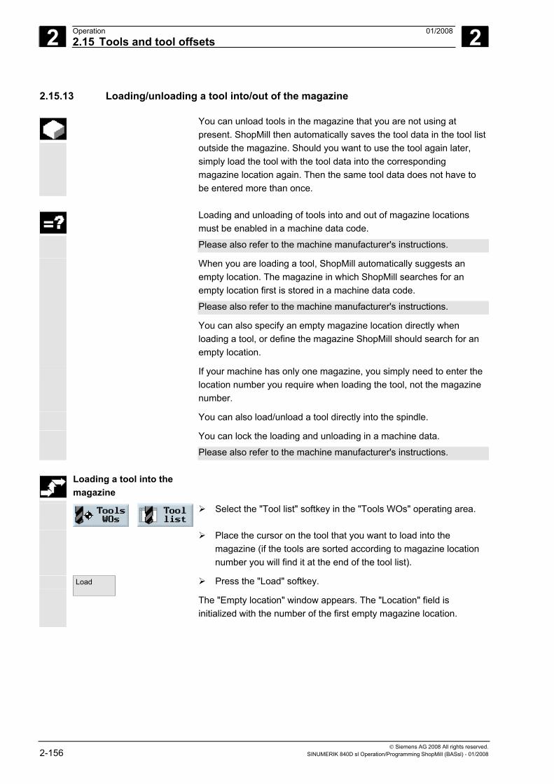
2 Operation 01/2008 2.15 Tools and tool offsets
2
© Siemens AG 2008 All rights reserved. 2-156 SINUMERIK 840D sl Operation/Programming ShopMill (BASsl) - 01/2008
2.15.13 Loading/unloading a tool into/out of the magazine
You can unload tools in the magazine that you are not using at present. ShopMill then automatically saves the tool data in the tool list outside the magazine. Should you want to use the tool again later, simply load the tool with the tool data into the corresponding magazine location again. Then the same tool data does not have to be entered more than once.
Loading and unloading of tools into and out of magazine locations
must be enabled in a machine data code.
Please also refer to the machine manufacturer's instructions.
When you are loading a tool, ShopMill automatically suggests an empty location. The magazine in which ShopMill searches for an empty location first is stored in a machine data code.
Please also refer to the machine manufacturer's instructions.
You can also specify an empty magazine location directly when loading a tool, or define the magazine ShopMill should search for an empty location.
If your machine has only one magazine, you simply need to enter the location number you require when loading the tool, not the magazine number.
You can also load/unload a tool directly into the spindle.
You can lock the loading and unloading in a machine data.
Please also refer to the machine manufacturer's instructions.
Loading a tool into the magazine
Select the "Tool list" softkey in the "Tools WOs" operating area.
Place the cursor on the tool that you want to load into the magazine (if the tools are sorted according to magazine location number you will find it at the end of the tool list).
Load
Press the "Load" softkey.
The "Empty location" window appears. The "Location" field is initialized with the number of the first empty magazine location.
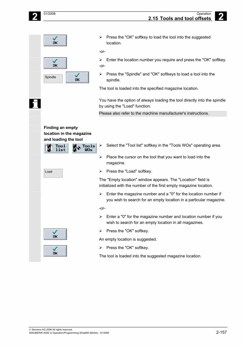
2 01/2008 Operation2.15 Tools and tool offsets
2
© Siemens AG 2008 All rights reserved. SINUMERIK 840D sl Operation/Programming ShopMill (BASsl) - 01/2008 2-157
Press the "OK" softkey to load the tool into the suggested location.
-or-
Enter the location number you require and press the "OK" softkey.-or-
Spindle
Press the "Spindle" and "OK" softkeys to load a tool into the spindle.
The tool is loaded into the specified magazine location.
You have the option of always loading the tool directly into the spindle by using the "Load" function.
Please also refer to the machine manufacturer's instructions.
Finding an empty location in the magazine and loading the tool
Select the "Tool list" softkey in the "Tools WOs" operating area.
Place the cursor on the tool that you want to load into the magazine.
Load
Press the "Load" softkey.
The "Empty location" window appears. The "Location" field is initialized with the number of the first empty magazine location.
Enter the magazine number and a "0" for the location number if you wish to search for an empty location in a particular magazine.
-or-
Enter a "0" for the magazine number and location number if you wish to search for an empty location in all magazines.
Press the "OK" softkey.
An empty location is suggested.
Press the "OK" softkey.
The tool is loaded into the suggested magazine location.
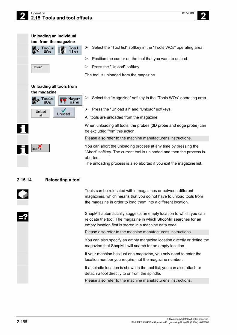
2 Operation 01/2008 2.15 Tools and tool offsets
2
© Siemens AG 2008 All rights reserved. 2-158 SINUMERIK 840D sl Operation/Programming ShopMill (BASsl) - 01/2008
Unloading an individual tool from the magazine
Select the "Tool list" softkey in the "Tools WOs" operating area.
Position the cursor on the tool that you want to unload.
Unload
Press the "Unload" softkey.
The tool is unloaded from the magazine.
Unloading all tools from the magazine
Select the "Magazine" softkey in the "Tools WOs" operating area.
Unload
all
Press the "Unload all" and "Unload" softkeys.
All tools are unloaded from the magazine.
When unloading all tools, the probes (3D probe and edge probe) can be excluded from this action.
Please also refer to the machine manufacturer's instructions.
You can abort the unloading process at any time by pressing the "Abort" softkey. The current tool is unloaded and then the process is aborted. The unloading process is also aborted if you exit the magazine list.
2.15.14 Relocating a tool
Tools can be relocated within magazines or between different magazines, which means that you do not have to unload tools from the magazine in order to load them into a different location.
ShopMill automatically suggests an empty location to which you can
relocate the tool. The magazine in which ShopMill searches for an empty location first is stored in a machine data code.
Please also refer to the machine manufacturer's instructions.
You can also specify an empty magazine location directly or define themagazine that ShopMill will search for an empty location.
If your machine has just one magazine, you only need to enter the location number you require, not the magazine number.
If a spindle location is shown in the tool list, you can also attach or detach a tool directly to or from the spindle.
Please also refer to the machine manufacturer's instructions.
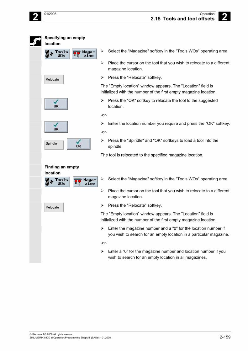
2 01/2008 Operation2.15 Tools and tool offsets
2
© Siemens AG 2008 All rights reserved. SINUMERIK 840D sl Operation/Programming ShopMill (BASsl) - 01/2008 2-159
Specifying an empty location
Select the "Magazine" softkey in the "Tools WOs" operating area.
Place the cursor on the tool that you wish to relocate to a different magazine location.
Relocate
Press the "Relocate" softkey.
The "Empty location" window appears. The "Location" field is initialized with the number of the first empty magazine location.
Press the "OK" softkey to relocate the tool to the suggested location.
-or-
Enter the location number you require and press the "OK" softkey.
-or-
Spindle
Press the "Spindle" and "OK" softkeys to load a tool into the spindle.
The tool is relocated to the specified magazine location.
Finding an empty location
Select the "Magazine" softkey in the "Tools WOs" operating area.
Place the cursor on the tool that you wish to relocate to a different magazine location.
Relocate
Press the "Relocate" softkey.
The "Empty location" window appears. The "Location" field is initialized with the number of the first empty magazine location.
Enter the magazine number and a "0" for the location number if you wish to search for an empty location in a particular magazine.
-or-
Enter a "0" for the magazine number and location number if you wish to search for an empty location in all magazines.
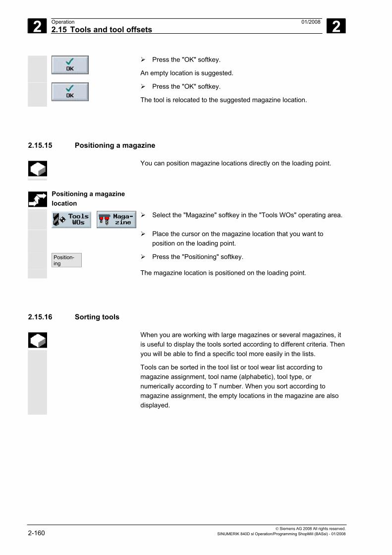
2 Operation 01/2008 2.15 Tools and tool offsets
2
© Siemens AG 2008 All rights reserved. 2-160 SINUMERIK 840D sl Operation/Programming ShopMill (BASsl) - 01/2008
Press the "OK" softkey.
An empty location is suggested.
Press the "OK" softkey.
The tool is relocated to the suggested magazine location.
2.15.15 Positioning a magazine
You can position magazine locations directly on the loading point.
Positioning a magazine
location
Select the "Magazine" softkey in the "Tools WOs" operating area.
Place the cursor on the magazine location that you want to position on the loading point.
Position- ing
Press the "Positioning" softkey.
The magazine location is positioned on the loading point.
2.15.16 Sorting tools
When you are working with large magazines or several magazines, it is useful to display the tools sorted according to different criteria. Then you will be able to find a specific tool more easily in the lists.
Tools can be sorted in the tool list or tool wear list according to magazine assignment, tool name (alphabetic), tool type, or numerically according to T number. When you sort according to magazine assignment, the empty locations in the magazine are also displayed.
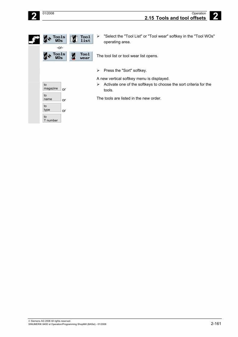
2 01/2008 Operation2.15 Tools and tool offsets
2
© Siemens AG 2008 All rights reserved. SINUMERIK 840D sl Operation/Programming ShopMill (BASsl) - 01/2008 2-161
-or-
"Select the "Tool List" or "Tool wear" softkey in the "Tool WOs" operating area.
The tool list or tool wear list opens.
Press the "Sort" softkey.
A new vertical softkey menu is displayed. to
magazine or toname or totype or to T number
Activate one of the softkeys to choose the sort criteria for the tools.
The tools are listed in the new order.
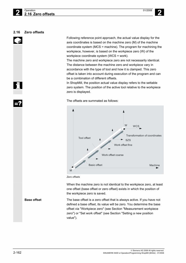
2 Operation 01/2008 2.16 Zero offsets
2
© Siemens AG 2008 All rights reserved. 2-162 SINUMERIK 840D sl Operation/Programming ShopMill (BASsl) - 01/2008
2.16 Zero offsets Following reference point approach, the actual value display for the
axis coordinates is based on the machine zero (M) of the machine coordinate system (MCS = machine). The program for machining the workpiece, however, is based on the workpiece zero (W) of the workpiece coordinate system (WCS = work). The machine zero and workpiece zero are not necessarily identical. The distance between the machine zero and workpiece vary in accordance with the type of tool and how it is clamped. This zero offset is taken into account during execution of the program and can be a combination of different offsets.
In ShopMill, the position actual value display refers to the settable zero system. The position of the active tool relative to the workpiece zero is displayed.
The offsets are summated as follows:
Basic offset Machine
M
WCSW
Tool offset
Work offset coarse
Transformation of coordinates
Work offset fine
SZS
Zero offsets
When the machine zero is not identical to the workpiece zero, at least one offset (base offset or zero offset) exists in which the position of the workpiece zero is saved.
Base offset The base offset is a zero offset that is always active. If you have not defined a base offset, its value will be zero. You determine the base offset via "Workpiece zero" (see Section "Measurement workpiece zero") or "Set work offset" (see Section "Setting a new position value").
2 01/2008 Operation2.16 Zero offsets
2
© Siemens AG 2008 All rights reserved. SINUMERIK 840D sl Operation/Programming ShopMill (BASsl) - 01/2008 2-163
Zero offsets
Every zero offset (G54 to G57, G505 to G599) consists of a coarse offset and a fine offset. You can call the work offsets from any sequence program (coarse and fine offsets are added together). You can save the workpiece zero, for example, in the coarse offset, and then store the offset that occurs when a new workpiece is clamped between the old and the new workpiece zero in the fine offset.
Fine offsets must be set up by the machine manufacturer.
Please also refer to the machine manufacturer's instructions.
Pour savoir comment définir et appeler les décalages d'origine, voyez les chapitres "Définir des décalages d'origine" et "Sélectionner des décalages d'origine".
Coordinate transformations
You always program coordinate transformations for a specific sequence program. They are defined by: • Offset • Rotation • Scaling • Mirroring (Voir au chapitre "Définir les transformations de coordonnées")
Total offset The total offset is calculated from the sum of all offsets and coordinate transformations.
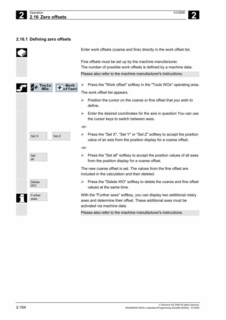
2 Operation 01/2008 2.16 Zero offsets
2
© Siemens AG 2008 All rights reserved. 2-164 SINUMERIK 840D sl Operation/Programming ShopMill (BASsl) - 01/2008
2.16.1 Defining zero offsets
Enter work offsets (coarse and fine) directly in the work offset list.
Fine offsets must be set up by the machine manufacturer. The number of possible work offsets is defined by a machine data.
Please also refer to the machine manufacturer's instructions.
Press the "Work offset" softkey in the "Tools WOs" operating area.
The work offset list appears.
Position the cursor on the coarse or fine offset that you wish to define.
Enter the desired coordinates for the axis in question You can use the cursor keys to switch between axes.
-or-
Set X ...
Set Z
Press the "Set X", "Set Y" or "Set Z" softkey to accept the position value of an axis from the position display for a coarse offset.
-or-
Setall
Press the "Set all" softkey to accept the position values of all axes from the position display for a coarse offset.
The new coarse offset is set. The values from the fine offset are included in the calculation and then deleted.
DeleteWO
Press the "Delete WO" softkey to delete the coarse and fine offset values at the same time.
Further axes
With the "Further axes" softkey, you can display two additional rotary axes and determine their offset. These additional axes must be activated via machine data.
Please also refer to the machine manufacturer's instructions.
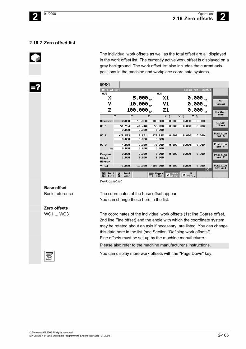
2 01/2008 Operation2.16 Zero offsets
2
© Siemens AG 2008 All rights reserved. SINUMERIK 840D sl Operation/Programming ShopMill (BASsl) - 01/2008 2-165
2.16.2 Zero offset list
The individual work offsets as well as the total offset are all displayed in the work offset list. The currently active work offset is displayed on agray background. The work offset list also includes the current axis positions in the machine and workpiece coordinate systems.
Work offset list
Base offset
Basic reference The coordinates of the base offset appear. You can change these here in the list.
Zero offsets
WO1 ... WO3 The coordinates of the individual work offsets (1st line Coarse offset, 2nd line Fine offset) and the angle with which the coordinate system may be rotated about an axis if necessary, are listed. You can change this data here in the list (see Section "Defining work offsets").
Fine offsets must be set up by the machine manufacturer.
Please also refer to the machine manufacturer's instructions.
You can display more work offsets with the "Page Down" key.
2 Operation 01/2008 2.16 Zero offsets
2
© Siemens AG 2008 All rights reserved. 2-166 SINUMERIK 840D sl Operation/Programming ShopMill (BASsl) - 01/2008
Coordinate transformations
Program The active coordinates of the "Offset" transformation are displayed as well as the angle set in the "Rotation" transformation by which the coordinate system rotates. You cannot edit these values here.
Scale The active scaling factor for the "Scaling" transformation is displayed for the respective axis. You cannot edit these values here.
Mirror The mirror axis that was defined by means of the "Mirroring" transformation is displayed. You cannot edit these values here.
Total offset
Total The total offset resulting from the base offset and all active work offsets and coordinate transformations appears.
Further axes
With the "Further axes" softkey, you can display two additional rotary axes and determine their offset. These additional axes must be activated via machine data.
Please also refer to the machine manufacturer's instructions.
Press the "Work offset" softkey in the "Tools WOs" operating area.
The work offset list appears.
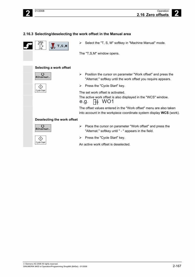
2 01/2008 Operation2.16 Zero offsets
2
© Siemens AG 2008 All rights reserved. SINUMERIK 840D sl Operation/Programming ShopMill (BASsl) - 01/2008 2-167
2.16.3 Selecting/deselecting the work offset in the Manual area
Jog
Select the "T, S, M" softkey in "Machine Manual" mode.
The "T,S,M" window opens. Selecting a work offset
Position the cursor on parameter "Work offset" and press the "Alternat." softkey until the work offset you require appears.
Cycle Start
Press the "Cycle Start" key.
The set work offset is activated. The active work offset is also displayed in the "WCS" window.
WO1e.g. The offset values entered in the "Work offset" menu are also taken
into account in the workpiece coordinate system display WCS (work).
Deselecting the work offset
Place the cursor on parameter "Work offset" and press the "Alternat." softkey until " - " appears in the field.
Cycle Start
Press the "Cycle Start" key.
An active work offset is deselected.
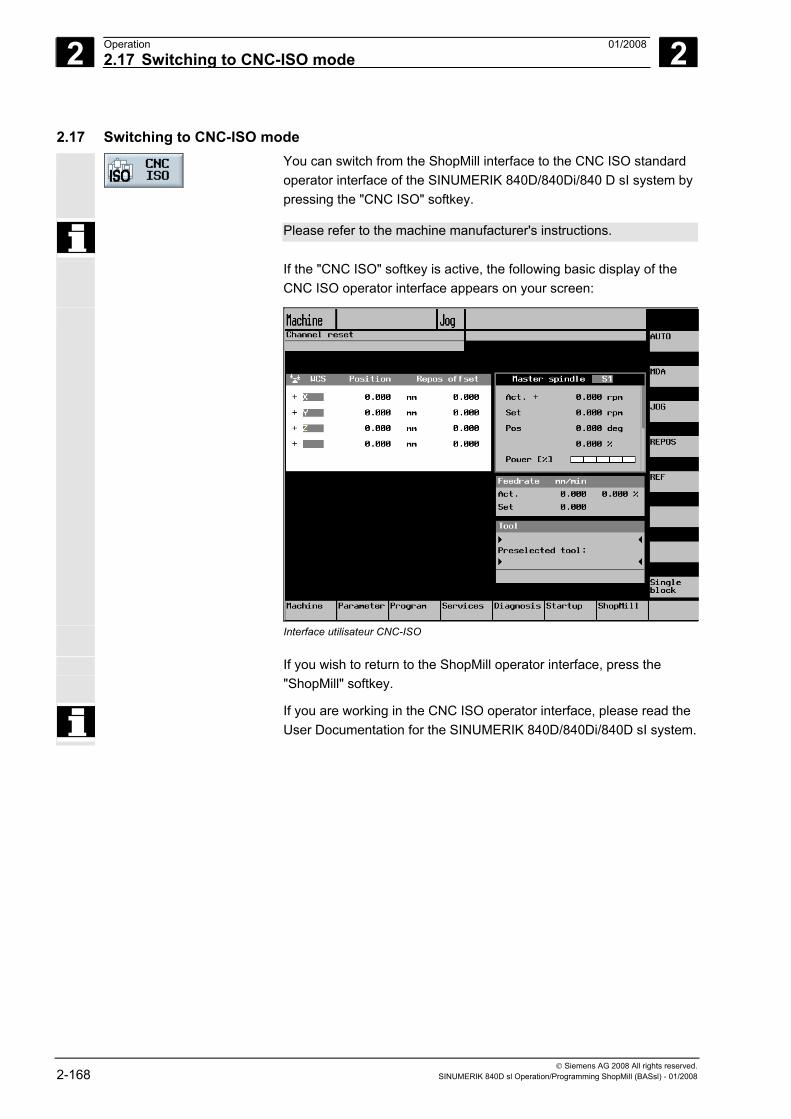
2 Operation 01/2008 2.17 Switching to CNC-ISO mode
2
© Siemens AG 2008 All rights reserved. 2-168 SINUMERIK 840D sl Operation/Programming ShopMill (BASsl) - 01/2008
2.17 Switching to CNC-ISO mode
You can switch from the ShopMill interface to the CNC ISO standard operator interface of the SINUMERIK 840D/840Di/840 D sI system by pressing the "CNC ISO" softkey.
Please refer to the machine manufacturer's instructions.
If the "CNC ISO" softkey is active, the following basic display of the CNC ISO operator interface appears on your screen:
Interface utilisateur CNC-ISO
If you wish to return to the ShopMill operator interface, press the "ShopMill" softkey.
If you are working in the CNC ISO operator interface, please read the User Documentation for the SINUMERIK 840D/840Di/840D sI system.
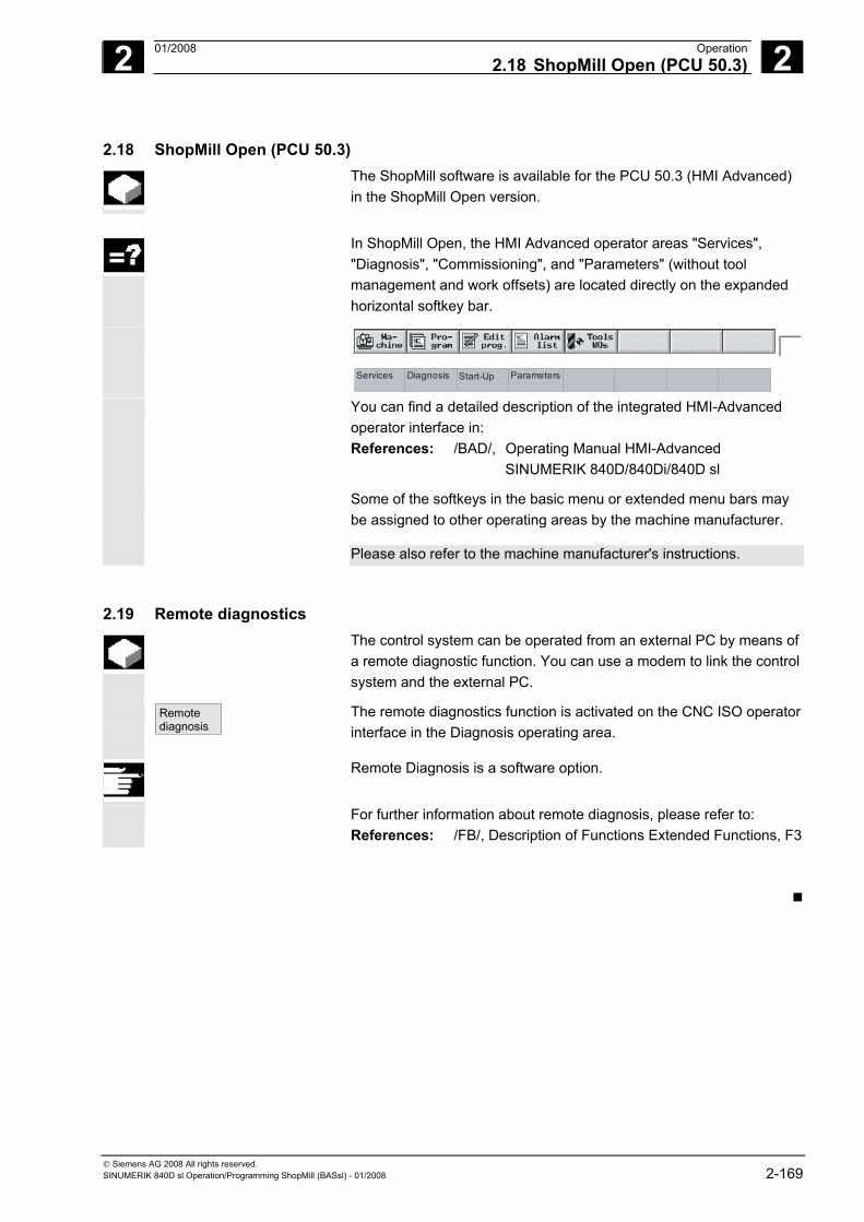
2 01/2008 Operation2.18 ShopMill Open (PCU 50.3)
2
© Siemens AG 2008 All rights reserved. SINUMERIK 840D sl Operation/Programming ShopMill (BASsl) - 01/2008 2-169
2.18 ShopMill Open (PCU 50.3) The ShopMill software is available for the PCU 50.3 (HMI Advanced)
in the ShopMill Open version.
In ShopMill Open, the HMI Advanced operator areas "Services",
"Diagnosis", "Commissioning", and "Parameters" (without tool management and work offsets) are located directly on the expanded horizontal softkey bar.
ParametersDiagnosis Start-UpServices
You can find a detailed description of the integrated HMI-Advanced operator interface in: References: /BAD/, Operating Manual HMI-Advanced SINUMERIK 840D/840Di/840D sl
Some of the softkeys in the basic menu or extended menu bars may be assigned to other operating areas by the machine manufacturer.
Please also refer to the machine manufacturer's instructions.
2.19 Remote diagnostics The control system can be operated from an external PC by means of
a remote diagnostic function. You can use a modem to link the control system and the external PC.
Remotediagnosis
The remote diagnostics function is activated on the CNC ISO operator interface in the Diagnosis operating area.
Remote Diagnosis is a software option.
For further information about remote diagnosis, please refer to: References: /FB/, Description of Functions Extended Functions, F3
2 Operation 01/2008 2.19 Remote diagnostics
2
© Siemens AG 2008 All rights reserved. 2-170 SINUMERIK 840D sl Operation/Programming ShopMill (BASsl) - 01/2008
Notes
3 01/2008 Programming with ShopMill 3
© Siemens AG 2008 All rights reserved. SINUMERIK 840D sl Operation/Programming ShopMill (BASsl) - 01/2008 3-171
Programming with ShopMill 3.1 Programming fundamentals.................................................................................... 3-173
3.2 Program structure ................................................................................................... 3-176
3.3 Creating a sequence program ................................................................................ 3-177
3.3.1 Creating a new program; defining a blank .............................................................. 3-177 3.3.2 Programming new blocks........................................................................................ 3-181 3.3.3 Changing program blocks ....................................................................................... 3-183 3.3.4 Program editor ........................................................................................................ 3-184 3.3.5 Specifying a quantity............................................................................................... 3-187
3.4 Programming the tool, offset value, and spindle speed.......................................... 3-188
3.5 Contour milling ........................................................................................................ 3-189 3.5.1 Representation of the contour................................................................................. 3-192 3.5.2 Creating a new contour........................................................................................... 3-194 3.5.3 Creating contour elements...................................................................................... 3-196 3.5.4 Changing a contour................................................................................................. 3-201 3.5.5 Programming examples for freely defined contours ............................................... 3-203 3.5.6 Path milling.............................................................................................................. 3-207 3.5.7 Predrilling a contour pocket .................................................................................... 3-210 3.5.8 Milling a contour pocket (roughing)......................................................................... 3-213 3.5.9 Removing residual material from a contour pocket ................................................ 3-215 3.5.10 Finishing the contour pocket ................................................................................... 3-217 3.5.11 Chamfering a contour pocket.................................................................................. 3-219 3.5.12 Milling a contour spigot (roughing).......................................................................... 3-220 3.5.13 Removing residual material from a contour spigot ................................................. 3-221 3.5.14 Finishing the contour spigot .................................................................................... 3-223 3.5.15 Chamfering a contour spigot................................................................................... 3-224
3.6 Linear or circular path motions................................................................................ 3-225 3.6.1 Straight.................................................................................................................... 3-225 3.6.2 Circle with known center point ................................................................................ 3-227 3.6.3 Circle with known radius ......................................................................................... 3-228 3.6.4 Helix ........................................................................................................................ 3-229 3.6.5 Polar coordinates .................................................................................................... 3-230 3.6.6 Straight polar........................................................................................................... 3-231 3.6.7 Circle polar .............................................................................................................. 3-232 3.6.8 Programming examples for polar coordinates ........................................................ 3-233
3.7 Drilling ..................................................................................................................... 3-234 3.7.1 Centering................................................................................................................. 3-234 3.7.2 Drilling and reaming ................................................................................................ 3-235 3.7.3 Deep-hole drilling .................................................................................................... 3-236 3.7.4 Boring...................................................................................................................... 3-238 3.7.5 Tapping ................................................................................................................... 3-239 3.7.6 Thread milling.......................................................................................................... 3-241 3.7.7 Drill and thread milling ............................................................................................ 3-245
3 Programming with ShopMill 01/2008 3
© Siemens AG 2008 All rights reserved. 3-172 SINUMERIK 840D sl Operation/Programming ShopMill (BASsl) - 01/2008
3.7.8 Positioning on freely programmable positions and position patterns......................3-247 3.7.9 Freely programmable positions...............................................................................3-248 3.7.10 Line position pattern................................................................................................3-252 3.7.11 Matrix position pattern.............................................................................................3-253 3.7.12 Box position pattern.................................................................................................3-254 3.7.13 Full circle position pattern .......................................................................................3-256 3.7.14 Pitch circle position pattern .....................................................................................3-258 3.7.15 Including and skipping positions .............................................................................3-260 3.7.16 Obstacle ..................................................................................................................3-261 3.7.17 Repeating positions.................................................................................................3-263 3.7.18 Programming examples for drilling..........................................................................3-264
3.8 Milling ......................................................................................................................3-266 3.8.1 Face milling .............................................................................................................3-266 3.8.2 Rectangular pocket .................................................................................................3-269 3.8.3 Circular pocket ........................................................................................................3-273 3.8.4 Rectangular spigot ..................................................................................................3-276 3.8.5 Circular spigot .........................................................................................................3-279 3.8.6 Longitudinal slot ......................................................................................................3-281 3.8.7 Circumferential slot..................................................................................................3-284 3.8.8 Open slot .................................................................................................................3-287 3.8.9 Use of position patterns for milling ..........................................................................3-292 3.8.10 Engraving ................................................................................................................3-295
3.9 Measurement ..........................................................................................................3-300 3.9.1 Measuring the workpiece zero ................................................................................3-300 3.9.2 Measuring the tool...................................................................................................3-302 3.9.3 Calibrating the probe...............................................................................................3-304
3.10 Miscellaneous functions ..........................................................................................3-305 3.10.1 Calling a subroutine.................................................................................................3-305 3.10.2 Repeating program blocks ......................................................................................3-307 3.10.3 Changing program settings .....................................................................................3-309 3.10.4 Calling zero offsets..................................................................................................3-309 3.10.5 Defining coordinate transformations .......................................................................3-311 3.10.6 Cylinder surface transformation ..............................................................................3-314 3.10.7 Swiveling .................................................................................................................3-317 3.10.8 Miscellaneous functions ..........................................................................................3-323
3.11 Inserting G code into the sequence program..........................................................3-324
3 01/2008 Programming with ShopMill3.1 Programming fundamentals
3
© Siemens AG 2008 All rights reserved. SINUMERIK 840D sl Operation/Programming ShopMill (BASsl) - 01/2008 3-173
3.1 Programming fundamentals Important! Please pay particular attention to the following fundamental
principles when writing programs for your machine tool! Axes The 3 main axes on milling machines are designated as X, Y and Z.
Axis Z is normally the tool axis. Metric dimension
data input or inch The control system can process both metric and inch dimensions. Depending on the basic setting you choose, the control interprets all geometric values as either metric or inch dimensions. Irrespective of the basic setting, you can set metric or inch dimensions in the program header (define blank). All dimensions stated in this section are metric.
Absolute dimensioning With the absolute dimensioning method, dimensions refer to the zero
point of the coordinate system of the total offset. Incremental dimensioning With the incremental dimensioning method, the programmed
positional numerical value corresponds to the path to be traversed. The leading sign indicates the traversing direction.
Tool T A tool must be programmed for every cutting operation. With the
ShopMill machining cycles, a tool selection is already integrated in every parameterization screen form. Exception: You must select a tool before programming simple straight lines and circles. Tool selection is modal with straight line/circle, i.e. if several machining steps with the same tool occur in succession, you only need to program the tool for the 1st straight line/circle.
Tool length compensation Tool length compensations take effect immediately the tool is loaded
into the spindle. Different tool offsets can be assigned to each tool with multiple cutting edges. The tool length compensation of the spindle tool remains active even after the program has been executed (RESET).
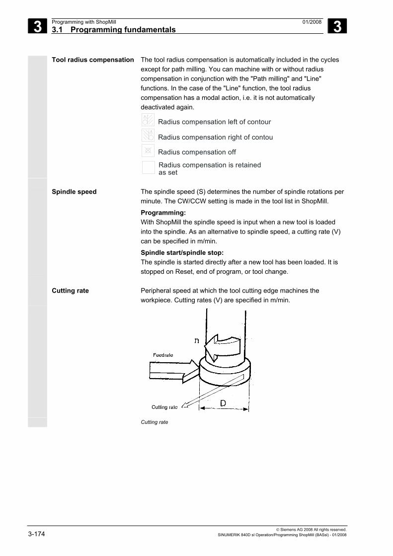
3 Programming with ShopMill 01/2008 3.1 Programming fundamentals
3
© Siemens AG 2008 All rights reserved. 3-174 SINUMERIK 840D sl Operation/Programming ShopMill (BASsl) - 01/2008
Tool radius compensation The tool radius compensation is automatically included in the cycles except for path milling. You can machine with or without radius compensation in conjunction with the "Path milling" and "Line" functions. In the case of the "Line" function, the tool radius compensation has a modal action, i.e. it is not automatically deactivated again.
Radius compensation left of contour
Radius compensation right of contou
Radius compensation off
Radius compensation is retainedas set
Spindle speed The spindle speed (S) determines the number of spindle rotations per
minute. The CW/CCW setting is made in the tool list in ShopMill.
Programming: With ShopMill the spindle speed is input when a new tool is loaded into the spindle. As an alternative to spindle speed, a cutting rate (V) can be specified in m/min.
Spindle start/spindle stop: The spindle is started directly after a new tool has been loaded. It is stopped on Reset, end of program, or tool change.
Cutting rate Peripheral speed at which the tool cutting edge machines the
workpiece. Cutting rates (V) are specified in m/min.
Cutting rate
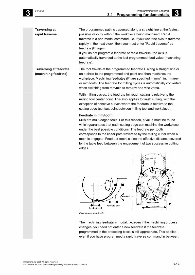
3 01/2008 Programming with ShopMill3.1 Programming fundamentals
3
© Siemens AG 2008 All rights reserved. SINUMERIK 840D sl Operation/Programming ShopMill (BASsl) - 01/2008 3-175
Traversing at rapid traverse
The programmed path is traversed along a straight line at the fastest possible velocity without the workpiece being machined. Rapid traverse is a non-modal command, i.e. if you want the axis to traverse rapidly in the next block, then you must enter "Rapid traverse" as feedrate (F) again. If you do not program a feedrate or rapid traverse, the axis is automatically traversed at the last programmed feed value (machining feedrate).
Traversing at feedrate (machining feedrate)
The tool travels at the programmed feedrate F along a straight line or on a circle to the programmed end point and then machines the workpiece. Machining feedrates (F) are specified in mm/min, mm/rev or mm/tooth. The feedrate for milling cycles is automatically converted when switching from mm/min to mm/rev and vice versa.
With milling cycles, the feedrate for rough cutting is relative to the milling tool center point. This also applies to finish cutting, with the exception of concave curves where the feedrate is relative to the cutting edge (contact point between milling tool and workpiece).
Feedrate in mm/tooth Mills are multi-edged tools. For this reason, a value must be found
which guarantees that each cutting edge can machine the workpiece under the best possible conditions. The feedrate per tooth corresponds to the linear path traversed by the milling cutter when a tooth is engaged. Feed per tooth is also the effective distance covered by the table feed between the engagement of two successive cutting edges.
Feedrate in mm/tooth The machining feedrate is modal, i.e. even if the machining process
changes, you need not enter a new feedrate if the feedrate programmed in the preceding block is still appropriate. This applies even if you have programmed a rapid traverse command in between.
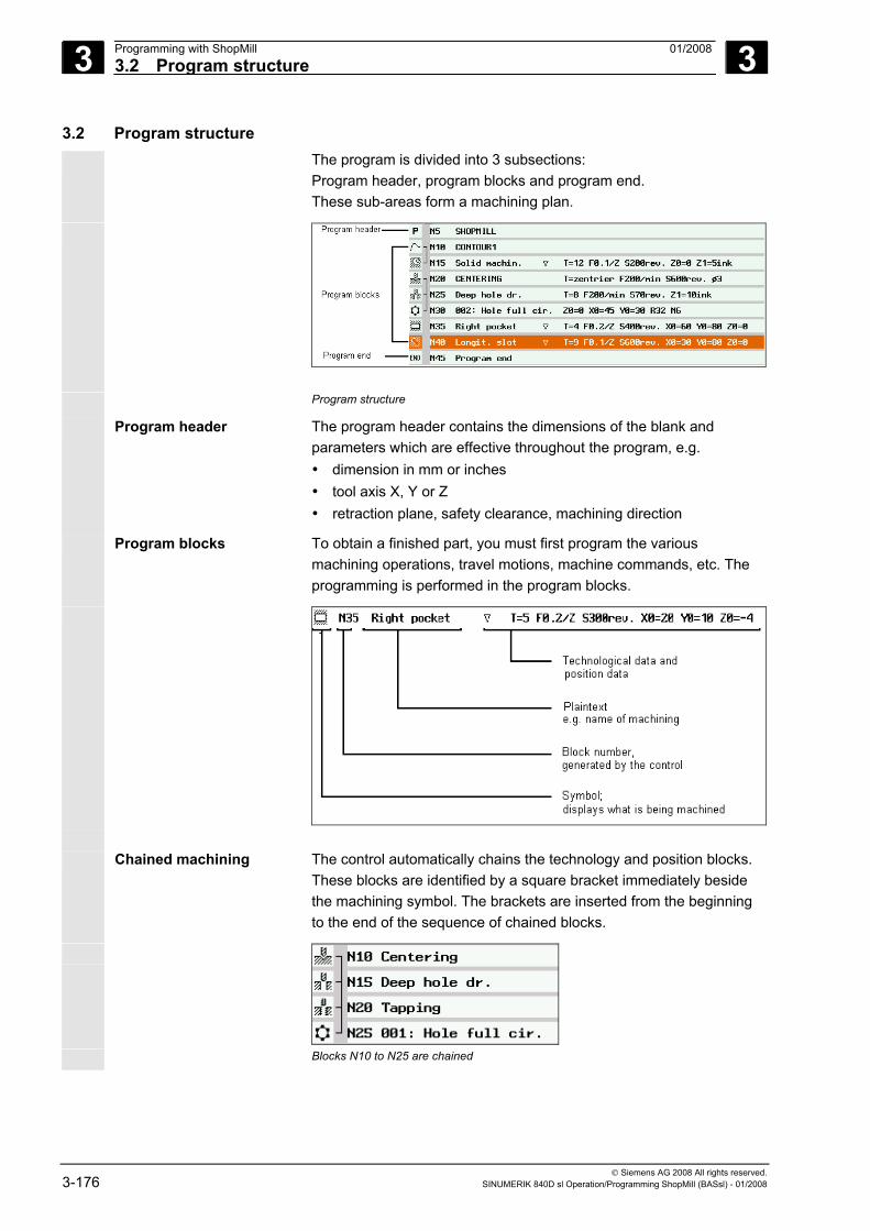
3 Programming with ShopMill 01/2008 3.2 Program structure
3
© Siemens AG 2008 All rights reserved. 3-176 SINUMERIK 840D sl Operation/Programming ShopMill (BASsl) - 01/2008
3.2 Program structure The program is divided into 3 subsections:
Program header, program blocks and program end. These sub-areas form a machining plan.
Program structure
Program header The program header contains the dimensions of the blank and parameters which are effective throughout the program, e.g. • dimension in mm or inches • tool axis X, Y or Z • retraction plane, safety clearance, machining direction
Program blocks To obtain a finished part, you must first program the various machining operations, travel motions, machine commands, etc. The programming is performed in the program blocks.
Chained machining The control automatically chains the technology and position blocks.
These blocks are identified by a square bracket immediately beside the machining symbol. The brackets are inserted from the beginning to the end of the sequence of chained blocks.
Blocks N10 to N25 are chained
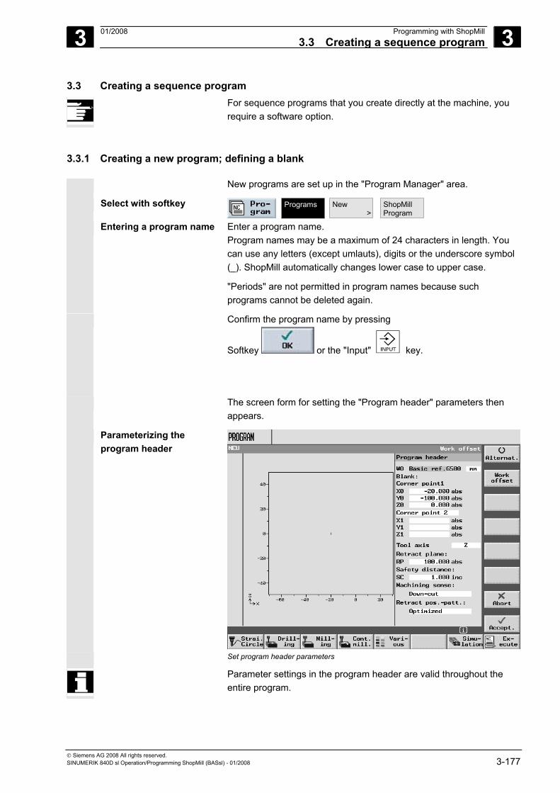
3 01/2008 Programming with ShopMill3.3 Creating a sequence program
3
© Siemens AG 2008 All rights reserved. SINUMERIK 840D sl Operation/Programming ShopMill (BASsl) - 01/2008 3-177
3.3 Creating a sequence program For sequence programs that you create directly at the machine, you
require a software option.
3.3.1 Creating a new program; defining a blank
New programs are set up in the "Program Manager" area.
Select with softkey
Programs
New >
ShopMillProgram
Entering a program name Enter a program name. Program names may be a maximum of 24 characters in length. You can use any letters (except umlauts), digits or the underscore symbol (_). ShopMill automatically changes lower case to upper case.
"Periods" are not permitted in program names because such programs cannot be deleted again.
Confirm the program name by pressing
Softkey or the "Input" key.
The screen form for setting the "Program header" parameters then appears.
Parameterizing the program header
Set program header parameters
Parameter settings in the program header are valid throughout the entire program.
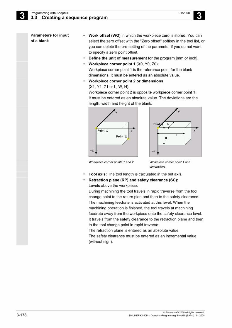
3 Programming with ShopMill 01/2008 3.3 Creating a sequence program
3
© Siemens AG 2008 All rights reserved. 3-178 SINUMERIK 840D sl Operation/Programming ShopMill (BASsl) - 01/2008
Parameters for input of a blank
• Work offset (WO) in which the workpiece zero is stored. You can select the zero offset with the "Zero offset" softkey in the tool list, or you can delete the pre-setting of the parameter if you do not want to specify a zero point offset.
• Define the unit of measurement for the program [mm or inch]. • Workpiece corner point 1 (X0, Y0, Z0):
Workpiece corner point 1 is the reference point for the blank dimensions. It must be entered as an absolute value.
• Workpiece corner point 2 or dimensions (X1, Y1, Z1 or L, W, H): Workpiece corner point 2 is opposite workpiece corner point 1. It must be entered as an absolute value. The deviations are the length, width and height of the blank.
Workpiece corner points 1 and 2 Workpiece corner point 1 and dimensions
• Tool axis: The tool length is calculated in the set axis. • Retraction plane (RP) and safety clearance (SC):
Levels above the workpiece. During machining the tool travels in rapid traverse from the tool change point to the return plan and then to the safety clearance. The machining feedrate is activated at this level. When the machining operation is finished, the tool travels at machining feedrate away from the workpiece onto the safety clearance level. It travels from the safety clearance to the retraction plane and then to the tool change point in rapid traverse. The retraction plane is entered as an absolute value. The safety clearance must be entered as an incremental value (without sign).
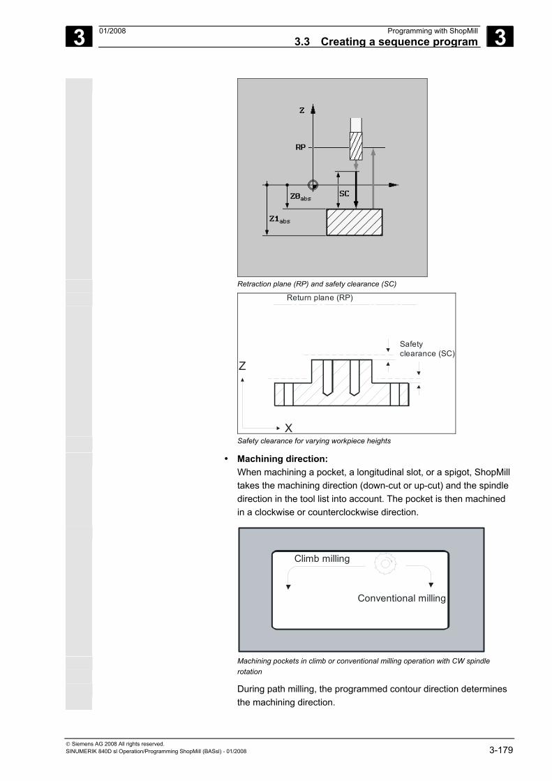
3 01/2008 Programming with ShopMill3.3 Creating a sequence program
3
© Siemens AG 2008 All rights reserved. SINUMERIK 840D sl Operation/Programming ShopMill (BASsl) - 01/2008 3-179
Retraction plane (RP) and safety clearance (SC)
X
Z
Safetyclearance (SC)
Return plane (RP)
Safety clearance for varying workpiece heights
• Machining direction: When machining a pocket, a longitudinal slot, or a spigot, ShopMill
takes the machining direction (down-cut or up-cut) and the spindle direction in the tool list into account. The pocket is then machined in a clockwise or counterclockwise direction.
Climb milling
Conventional milling
Machining pockets in climb or conventional milling operation with CW spindle
rotation
During path milling, the programmed contour direction determines the machining direction.
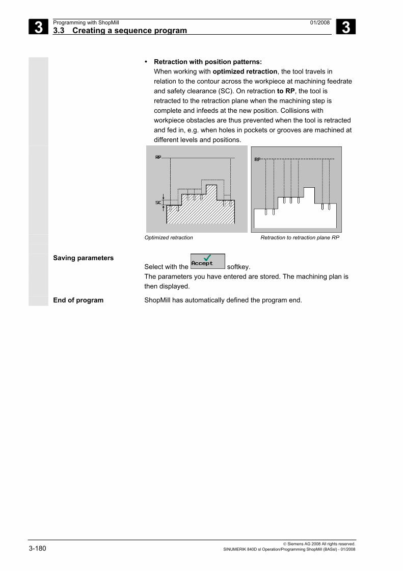
3 Programming with ShopMill 01/2008 3.3 Creating a sequence program
3
© Siemens AG 2008 All rights reserved. 3-180 SINUMERIK 840D sl Operation/Programming ShopMill (BASsl) - 01/2008
• Retraction with position patterns: When working with optimized retraction, the tool travels in relation to the contour across the workpiece at machining feedrate and safety clearance (SC). On retraction to RP, the tool is retracted to the retraction plane when the machining step is complete and infeeds at the new position. Collisions with workpiece obstacles are thus prevented when the tool is retracted and fed in, e.g. when holes in pockets or grooves are machined at different levels and positions.
Optimized retraction Retraction to retraction plane RP Saving parameters
Select with the softkey. The parameters you have entered are stored. The machining plan is
then displayed.
End of program ShopMill has automatically defined the program end.
3 01/2008 Programming with ShopMill3.3 Creating a sequence program
3
© Siemens AG 2008 All rights reserved. SINUMERIK 840D sl Operation/Programming ShopMill (BASsl) - 01/2008 3-181
3.3.2 Programming new blocks
Creating program blocks Once you have defined the blank, you can define machining operations, feedrates and positions in individual program blocks. You will be supported by "Help" displays for individual machining operations.
A large amount of memory is available for one program.
However, depending on the storage space required, you can only program a limited number of blocks.
• ShopMill on NCU (HMI Embedded sl) You can program a maximum of 1,000 blocks using the "Straight" function or a maximum of 600 blocks using the "Mill pocket" function.
• PCU 50.3 (HMI Advanced) You can program a maximum of 3,500 blocks using the "Straight" function or a maximum of 2,100 blocks using the "Mill pocket" function.
In the case of multiple clampings, a program can easily contain more
than the permissible number of program blocks. If a message tells you that too many blocks are present, group together machining operations with the same tool in a subroutine. That way, you can open and execute the program.
Note New programming blocks are always inserted after the selected block. You cannot program blocks before the program header or after program end.
Parameter input fields Feedrate:
If you do not program a value for feedrate (F) (empty field), the system uses the last programmed feedrate.
Clear an input field: Use the DEL key (or Backspace key) to clear an input field, i.e. to delete the programmed value.
Preset (default) or empty parameter fields: You must always enter a value in fields with a preset default. If you clear a default field, the "Accept" softkey disappears from the display!
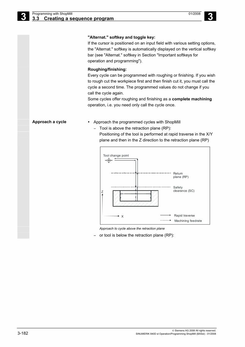
3 Programming with ShopMill 01/2008 3.3 Creating a sequence program
3
© Siemens AG 2008 All rights reserved. 3-182 SINUMERIK 840D sl Operation/Programming ShopMill (BASsl) - 01/2008
"Alternat." softkey and toggle key: If the cursor is positioned on an input field with various setting options, the "Alternat." softkey is automatically displayed on the vertical softkey bar (see "Alternat." softkey in Section "Important softkeys for operation and programming").
Roughing/finishing: Every cycle can be programmed with roughing or finishing. If you wish to rough cut the workpiece first and then finish cut it, you must call the cycle a second time. The programmed values do not change if you call the cycle again. Some cycles offer roughing and finishing as a complete machining operation, i.e. you need only call the cycle once.
Approach a cycle • Approach the programmed cycles with ShopMill − Tool is above the retraction plane (RP): Positioning of the tool is performed at rapid traverse in the X/Y
plane and then in the Z direction to the retraction plane (RP)
X
ZSafetyclearance (SC)
Returnplane (RP)
Tool change point
Rapid traverse
Machining feedrate
Approach to cycle above the retraction plane − or tool is below the retraction plane (RP):
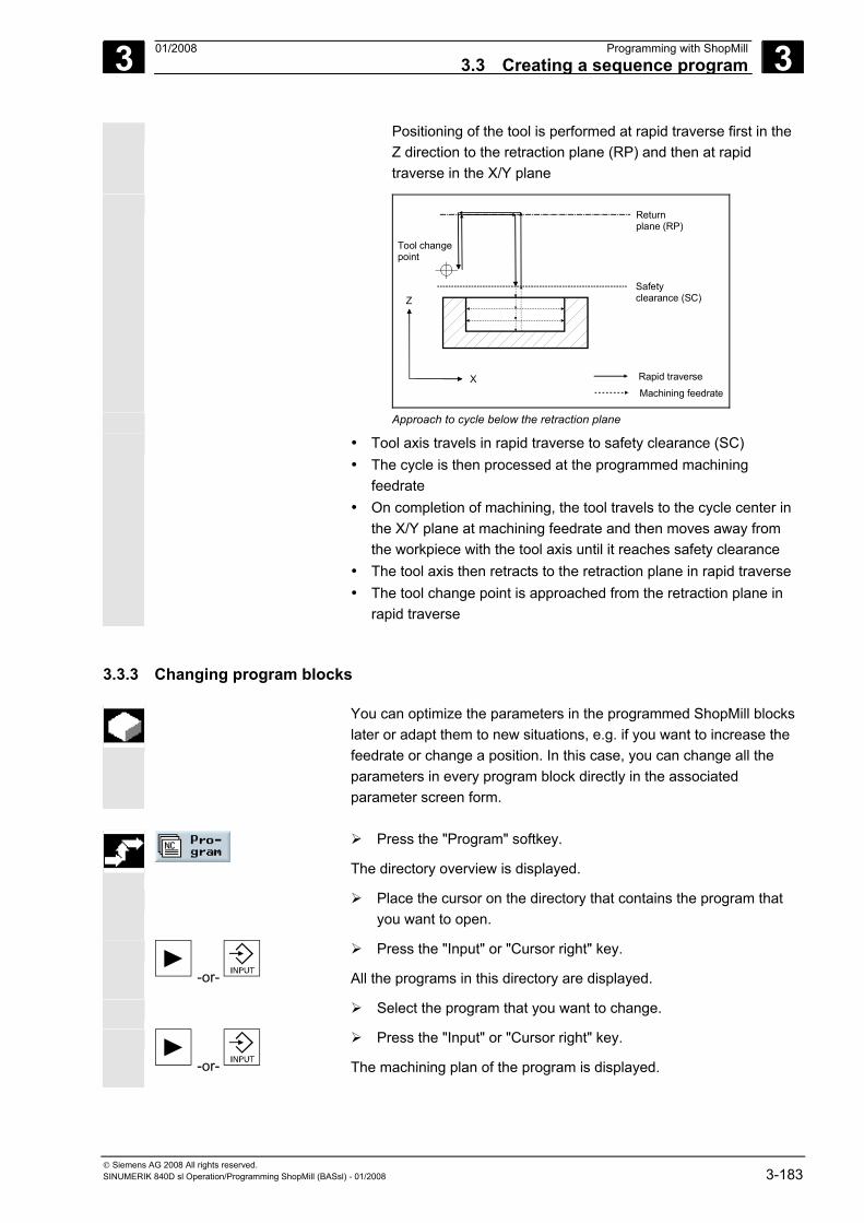
3 01/2008 Programming with ShopMill3.3 Creating a sequence program
3
© Siemens AG 2008 All rights reserved. SINUMERIK 840D sl Operation/Programming ShopMill (BASsl) - 01/2008 3-183
Positioning of the tool is performed at rapid traverse first in the Z direction to the retraction plane (RP) and then at rapid traverse in the X/Y plane
X
ZSafetyclearance (SC)
Returnplane (RP)
Tool changepoint
Rapid traverse
Machining feedrate
Approach to cycle below the retraction plane • Tool axis travels in rapid traverse to safety clearance (SC)
• The cycle is then processed at the programmed machining feedrate
• On completion of machining, the tool travels to the cycle center in the X/Y plane at machining feedrate and then moves away from the workpiece with the tool axis until it reaches safety clearance
• The tool axis then retracts to the retraction plane in rapid traverse • The tool change point is approached from the retraction plane in
rapid traverse
3.3.3 Changing program blocks
You can optimize the parameters in the programmed ShopMill blocks later or adapt them to new situations, e.g. if you want to increase the feedrate or change a position. In this case, you can change all the parameters in every program block directly in the associated parameter screen form.
Press the "Program" softkey.
The directory overview is displayed.
Place the cursor on the directory that contains the program that you want to open.
-or-
Press the "Input" or "Cursor right" key.
All the programs in this directory are displayed.
Select the program that you want to change.
-or-
Press the "Input" or "Cursor right" key.
The machining plan of the program is displayed.
3 Programming with ShopMill 01/2008 3.3 Creating a sequence program
3
© Siemens AG 2008 All rights reserved. 3-184 SINUMERIK 840D sl Operation/Programming ShopMill (BASsl) - 01/2008
Place the cursor on the desired program block in the machining plan.
Press the "Cursor right" key.
The parameter screen for the selected program block appears.
Make the desired changes.
-or-
Press the "Accept" softkey or the "Cursor left" key.
The changes are accepted in the program.
3.3.4 Program editor
You use the program editor when you want to change the sequence of program blocks within a program, delete program blocks or copy program blocks from one program to another.
The following functions are available in the program editor:
• Select You can select several program blocks simultaneously, for example, for cutting and pasting them subsequently.
• Copy/paste You can copy and paste program blocks within a program or between different programs.
• Cut You can cut and therefore delete program blocks. However, the program blocks remain in the buffer, so you can still paste them in somewhere else.
• Search You can search for a specific block number or any character string in a program.
• Rename You can rename a contour in the program editor, e.g. if you have copied the contour.
• Number If you insert a new or copied program block between two existing program blocks, ShopMill automatically generates a new block number. This block number may be higher than the one in the following block. You can use the "Numbering" function to number the program blocks in ascending order.
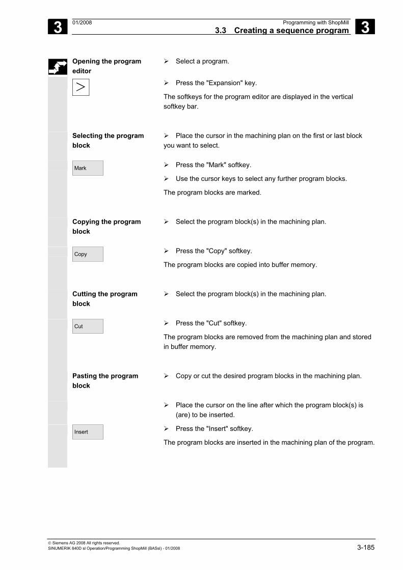
3 01/2008 Programming with ShopMill3.3 Creating a sequence program
3
© Siemens AG 2008 All rights reserved. SINUMERIK 840D sl Operation/Programming ShopMill (BASsl) - 01/2008 3-185
Opening the program editor
Select a program.
Press the "Expansion" key.
The softkeys for the program editor are displayed in the vertical softkey bar.
Selecting the program block
Place the cursor in the machining plan on the first or last block you want to select.
Mark
Press the "Mark" softkey.
Use the cursor keys to select any further program blocks.
The program blocks are marked.
Copying the program block
Select the program block(s) in the machining plan.
Copy
Press the "Copy" softkey.
The program blocks are copied into buffer memory.
Cutting the program block
Select the program block(s) in the machining plan.
Cut
Press the "Cut" softkey.
The program blocks are removed from the machining plan and stored in buffer memory.
Pasting the program block
Copy or cut the desired program blocks in the machining plan.
Place the cursor on the line after which the program block(s) is (are) to be inserted.
Insert
Press the "Insert" softkey.
The program blocks are inserted in the machining plan of the program.
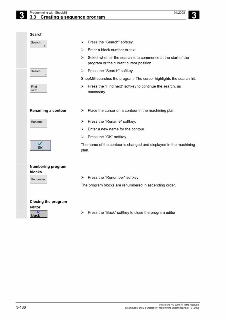
3 Programming with ShopMill 01/2008 3.3 Creating a sequence program
3
© Siemens AG 2008 All rights reserved. 3-186 SINUMERIK 840D sl Operation/Programming ShopMill (BASsl) - 01/2008
Search
Search >
Press the "Search" softkey.
Enter a block number or text.
Select whether the search is to commence at the start of the program or the current cursor position.
Search >
Press the "Search" softkey.
ShopMill searches the program. The cursor highlights the search hit.
Find next
Press the "Find next" softkey to continue the search, as necessary.
Renaming a contour
Place the cursor on a contour in the machining plan.
Rename
Press the "Rename" softkey.
Enter a new name for the contour.
Press the "OK" softkey.
The name of the contour is changed and displayed in the machining plan.
Numbering program blocks
Renumber
Press the "Renumber" softkey.
The program blocks are renumbered in ascending order.
Closing the program editor
Press the "Back" softkey to close the program editor.
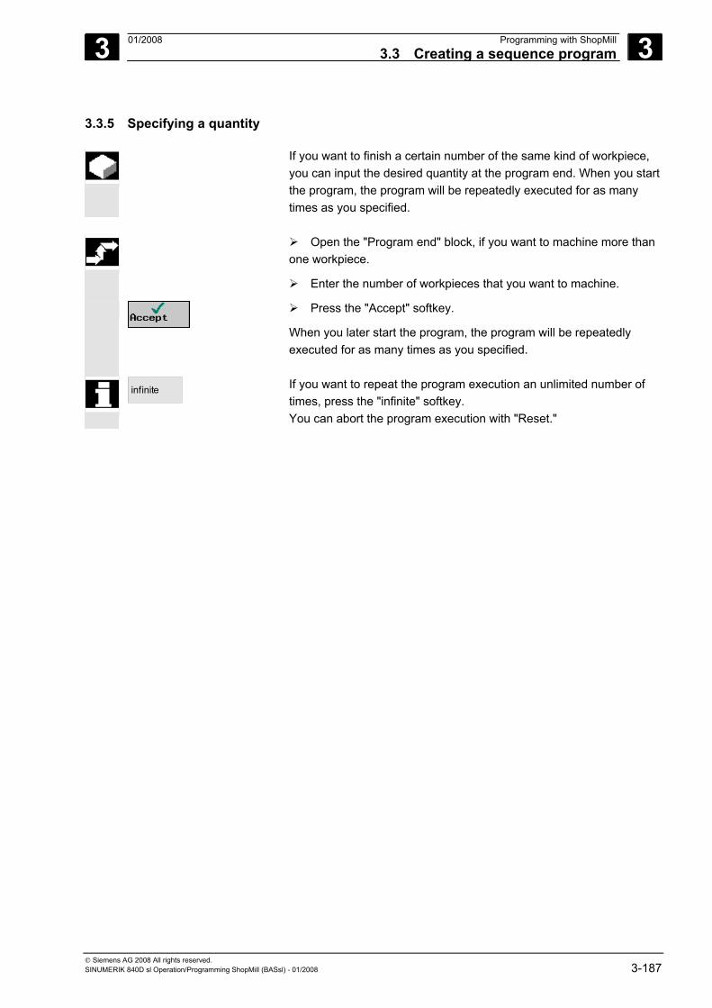
3 01/2008 Programming with ShopMill3.3 Creating a sequence program
3
© Siemens AG 2008 All rights reserved. SINUMERIK 840D sl Operation/Programming ShopMill (BASsl) - 01/2008 3-187
3.3.5 Specifying a quantity
If you want to finish a certain number of the same kind of workpiece, you can input the desired quantity at the program end. When you start the program, the program will be repeatedly executed for as many times as you specified.
Open the "Program end" block, if you want to machine more than
one workpiece.
Enter the number of workpieces that you want to machine.
Press the "Accept" softkey.
When you later start the program, the program will be repeatedly executed for as many times as you specified.
infinite
If you want to repeat the program execution an unlimited number of times, press the "infinite" softkey. You can abort the program execution with "Reset."
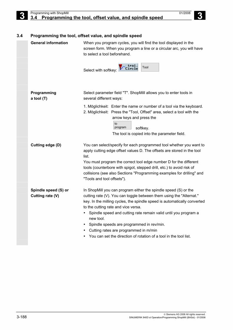
3 Programming with ShopMill 01/2008 3.4 Programming the tool, offset value, and spindle speed
3
© Siemens AG 2008 All rights reserved. 3-188 SINUMERIK 840D sl Operation/Programming ShopMill (BASsl) - 01/2008
3.4 Programming the tool, offset value, and spindle speed General information When you program cycles, you will find the tool displayed in the
screen form. When you program a line or a circular arc, you will have to select a tool beforehand.
Select with softkey: Tool
Programming
a tool (T) Select parameter field "T". ShopMill allows you to enter tools in several different ways:
1. Möglichkeit: Enter the name or number of a tool via the keyboard. 2. Möglichkeit: Press the "Tool, Offset" area, select a tool with the
arrow keys and press the
toprogram softkey.
The tool is copied into the parameter field. Cutting edge (D) You can select/specify for each programmed tool whether you want to
apply cutting edge offset values D. The offsets are stored in the tool list. You must program the correct tool edge number D for the different tools (counterbore with spigot, stepped drill, etc.) to avoid risk of collisions (see also Sections "Programming examples for drilling" and "Tools and tool offsets").
Spindle speed (S) or
Cutting rate (V) In ShopMill you can program either the spindle speed (S) or the cutting rate (V). You can toggle between them using the "Alternat." key. In the milling cycles, the spindle speed is automatically converted to the cutting rate and vice versa. • Spindle speed and cutting rate remain valid until you program a
new tool. • Spindle speeds are programmed in rev/min. • Cutting rates are programmed in m/min • You can set the direction of rotation of a tool in the tool list.
3 01/2008 Programming with ShopMill3.5 Contour milling
3
© Siemens AG 2008 All rights reserved. SINUMERIK 840D sl Operation/Programming ShopMill (BASsl) - 01/2008 3-189
Allowance (DR) You can program an allowance on the tool radius in this parameter input field. A finishing allowance is then left when the contour is machined (see also Section "Tools and tool offsets"). The DR parameter is active until a ShopMill cycle (drilling, missing, contour missing) is programmed.
Example You want to leave a finishing allowance of 0.5 mm on a contour. DR must then be programmed with 0.5 mm. With a setting of DR=0, the programmed contour is cut without a finishing allowance.
3.5 Contour milling The "Contour milling" function is used when you want to mill simple
and complex contours. You can define open contours or closed contours (pockets, islands, spigots) and machine them with path milling or milling cycles.
A contour comprises separate contour elements, whereby at least two
and up to 250 elements result in a defined contour. You can also program chamfers, radii or tangential transitions between the contour elements.
The integrated contour calculator calculates the intersection points of the individual contour elements taking into account the geometrical relationships, which allows you to enter incompletely dimensioned elements.
With contour milling, you must always program the geometry of the contour before you program the technology. You have the option of machining contours of any type by path milling, stock removal from pockets with or without islands, or clearing spigots.
Freely-definable contours
The machining of freely-definable open or closed contours is generally programmed as follows:
1. Enter contour You build up the contour gradually from a series of different contour elements.
2. Path milling (roughing) The contour is machined taking into account various approach and retract strategies.
3. Path milling (finishing) If you programmed a finishing allowance for roughing, the contour is machined again.
4. Path milling (chamfer) If you have planned edge breaking, chamfer the workpiece with a special tool.
3 Programming with ShopMill 01/2008 3.5 Contour milling
3
© Siemens AG 2008 All rights reserved. 3-190 SINUMERIK 840D sl Operation/Programming ShopMill (BASsl) - 01/2008
Contours for pockets or islands
Contours for pockets or islands must be closed, i.e. the start point and end point of the contour are identical. You can also mill pockets that contain one or more islands. The islands can also be located partially outside the pocket or overlap each other. ShopMill interprets the first contour specified as a pocket contour and all others as islands.
The machining of contour pockets with islands is generally programmed as follows:
1. Enter contour for the pocket You build up the contour pocket gradually from a series of different contour elements.
2. Enter contour for the island You enter the contour for the island after the contour for the pocket.
3. Centering predrilling of the contour pocket If you want to predrill the contour pocket, you can center the drill hole first to prevent the drill slipping.
4. Predrill contour pocket If you want the cutter to plunge into the material vertically and if a milling cutter with an end tooth is not available, you can predrill the pocket.
5. Remove stock from contour pocket with island (roughing) The stock is removed from the contour pocket complete with island taking into account various insertion strategies.
6. Remove residual material (roughing) During stock removal from the pocket, ShopMill automatically detects residual material that has been left. A suitable tool will allow you to remove this without having to machine the complete pocket again.
7. Finish contour pocket with island (finish edge/base) If you programmed a finishing allowance for the edge/base when you programmed roughing, the pocket edge/base will be machined again.
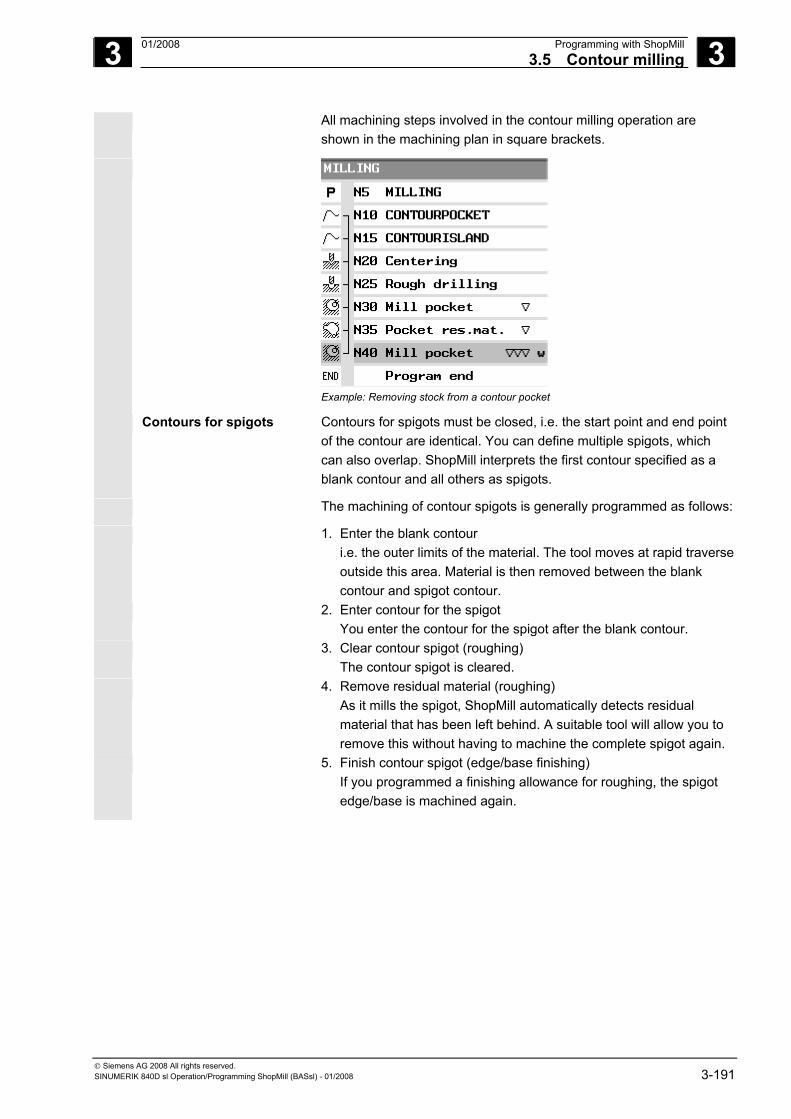
3 01/2008 Programming with ShopMill3.5 Contour milling
3
© Siemens AG 2008 All rights reserved. SINUMERIK 840D sl Operation/Programming ShopMill (BASsl) - 01/2008 3-191
All machining steps involved in the contour milling operation are shown in the machining plan in square brackets.
Example: Removing stock from a contour pocket
Contours for spigots
Contours for spigots must be closed, i.e. the start point and end point of the contour are identical. You can define multiple spigots, which can also overlap. ShopMill interprets the first contour specified as a blank contour and all others as spigots.
The machining of contour spigots is generally programmed as follows:
1. Enter the blank contour i.e. the outer limits of the material. The tool moves at rapid traverse outside this area. Material is then removed between the blank contour and spigot contour.
2. Enter contour for the spigot You enter the contour for the spigot after the blank contour.
3. Clear contour spigot (roughing) The contour spigot is cleared.
4. Remove residual material (roughing) As it mills the spigot, ShopMill automatically detects residual material that has been left behind. A suitable tool will allow you to remove this without having to machine the complete spigot again.
5. Finish contour spigot (edge/base finishing) If you programmed a finishing allowance for roughing, the spigot edge/base is machined again.
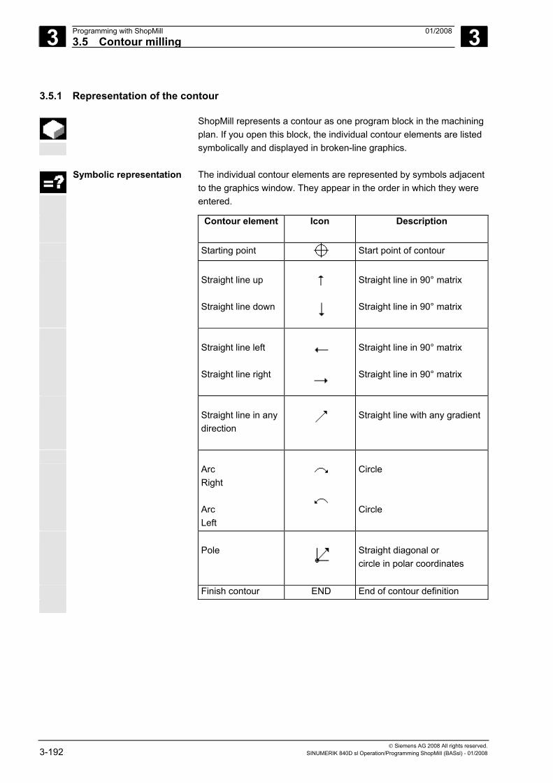
3 Programming with ShopMill 01/2008 3.5 Contour milling
3
© Siemens AG 2008 All rights reserved. 3-192 SINUMERIK 840D sl Operation/Programming ShopMill (BASsl) - 01/2008
3.5.1 Representation of the contour
ShopMill represents a contour as one program block in the machining plan. If you open this block, the individual contour elements are listed symbolically and displayed in broken-line graphics.
Symbolic representation The individual contour elements are represented by symbols adjacent
to the graphics window. They appear in the order in which they were entered.
Contour element Icon Description
Starting point Start point of contour
Straight line up Straight line down
Straight line in 90° matrix Straight line in 90° matrix
Straight line left Straight line right
Straight line in 90° matrix Straight line in 90° matrix
Straight line in any direction
Straight line with any gradient
Arc Right Arc Left
Circle Circle
Pole
Straight diagonal or circle in polar coordinates
Finish contour END End of contour definition
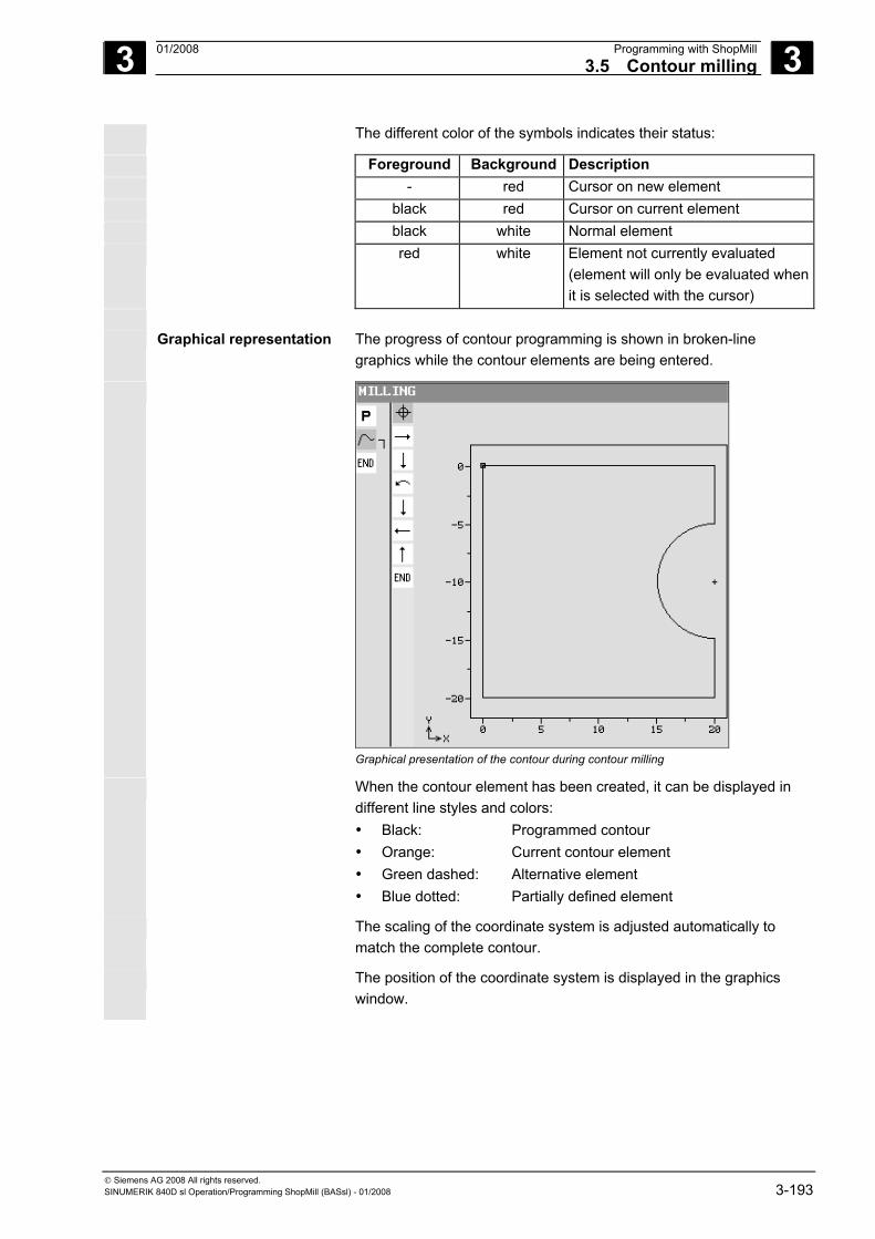
3 01/2008 Programming with ShopMill3.5 Contour milling
3
© Siemens AG 2008 All rights reserved. SINUMERIK 840D sl Operation/Programming ShopMill (BASsl) - 01/2008 3-193
The different color of the symbols indicates their status:
Foreground Background Description - red Cursor on new element black red Cursor on current element black white Normal element red white Element not currently evaluated
(element will only be evaluated when it is selected with the cursor)
Graphical representation The progress of contour programming is shown in broken-line
graphics while the contour elements are being entered.
Graphical presentation of the contour during contour milling
When the contour element has been created, it can be displayed in different line styles and colors: • Black: Programmed contour • Orange: Current contour element • Green dashed: Alternative element • Blue dotted: Partially defined element
The scaling of the coordinate system is adjusted automatically to match the complete contour.
The position of the coordinate system is displayed in the graphics window.
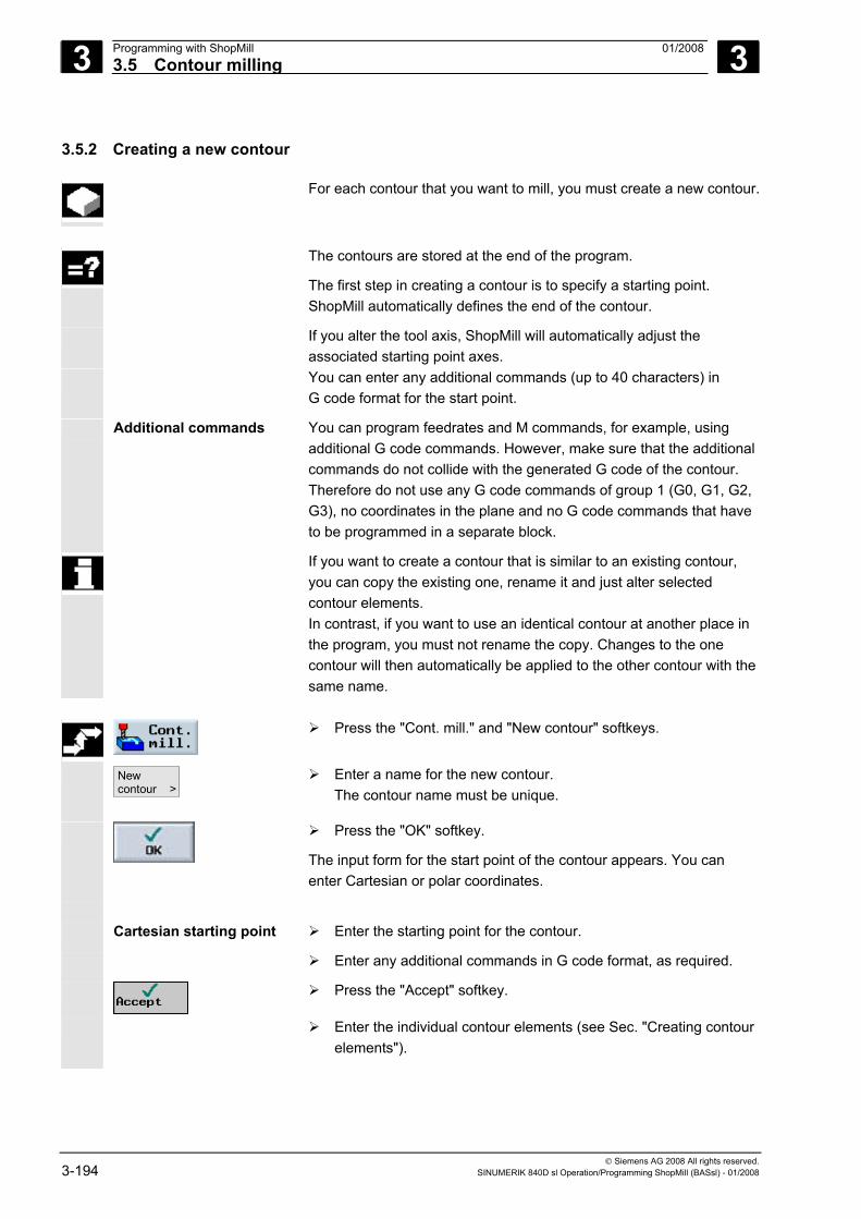
3 Programming with ShopMill 01/2008 3.5 Contour milling
3
© Siemens AG 2008 All rights reserved. 3-194 SINUMERIK 840D sl Operation/Programming ShopMill (BASsl) - 01/2008
3.5.2 Creating a new contour
For each contour that you want to mill, you must create a new contour.
The contours are stored at the end of the program.
The first step in creating a contour is to specify a starting point. ShopMill automatically defines the end of the contour.
If you alter the tool axis, ShopMill will automatically adjust the associated starting point axes.
You can enter any additional commands (up to 40 characters) in G code format for the start point.
Additional commands You can program feedrates and M commands, for example, using additional G code commands. However, make sure that the additional commands do not collide with the generated G code of the contour. Therefore do not use any G code commands of group 1 (G0, G1, G2, G3), no coordinates in the plane and no G code commands that have to be programmed in a separate block.
If you want to create a contour that is similar to an existing contour, you can copy the existing one, rename it and just alter selected contour elements. In contrast, if you want to use an identical contour at another place in the program, you must not rename the copy. Changes to the one contour will then automatically be applied to the other contour with the same name.
Press the "Cont. mill." and "New contour" softkeys.
Newcontour >
Enter a name for the new contour. The contour name must be unique.
Press the "OK" softkey.
The input form for the start point of the contour appears. You can enter Cartesian or polar coordinates.
Cartesian starting point Enter the starting point for the contour.
Enter any additional commands in G code format, as required.
Press the "Accept" softkey.
Enter the individual contour elements (see Sec. "Creating contour elements").
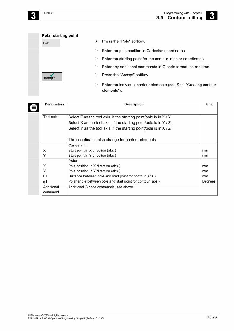
3 01/2008 Programming with ShopMill3.5 Contour milling
3
© Siemens AG 2008 All rights reserved. SINUMERIK 840D sl Operation/Programming ShopMill (BASsl) - 01/2008 3-195
Polar starting point Pole
Press the "Pole" softkey.
Enter the pole position in Cartesian coordinates.
Enter the starting point for the contour in polar coordinates.
Enter any additional commands in G code format, as required.
Press the "Accept" softkey.
Enter the individual contour elements (see Sec. "Creating contour elements").
Parameters Description Unit
Tool axis Select Z as the tool axis, if the starting point/pole is in X / Y Select X as the tool axis, if the starting point/pole is in Y / Z Select Y as the tool axis, if the starting point/pole is in X / Z The coordinates also change for contour elements
X Y
Cartesian: Start point in X direction (abs.) Start point in Y direction (abs.)
mm mm
X Y L1 ϕ1
Polar: Pole position in X direction (abs.) Pole position in Y direction (abs.) Distance between pole and start point for contour (abs.) Polar angle between pole and start point for contour (abs.)
mm mm mm Degrees
Additional command
Additional G code commands; see above
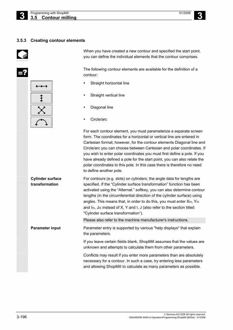
3 Programming with ShopMill 01/2008 3.5 Contour milling
3
© Siemens AG 2008 All rights reserved. 3-196 SINUMERIK 840D sl Operation/Programming ShopMill (BASsl) - 01/2008
3.5.3 Creating contour elements
When you have created a new contour and specified the start point, you can define the individual elements that the contour comprises.
The following contour elements are available for the definition of a
contour:
• Straight horizontal line
• Straight vertical line
• Diagonal line
• Circle/arc
For each contour element, you must parameterize a separate screen form. The coordinates for a horizontal or vertical line are entered in Cartesian format; however, for the contour elements Diagonal line and Circle/arc you can choose between Cartesian and polar coordinates. If you wish to enter polar coordinates you must first define a pole. If you have already defined a pole for the start point, you can also relate the polar coordinates to this pole. In this case there is therefore no need to define another pole.
Cylinder surface transformation
For contours (e.g. slots) on cylinders, the angle data for lengths are specified. If the “Cylinder surface transformation” function has been activated using the “Alternat.” softkey, you can also determine contour lengths (in the circumferential direction of the cylinder surface) using angles. This means that, in order to do this, you must enter Xα, Yα and Iα, Jα instead of X, Y and I, J (also refer to the section titled "Cylinder surface transformation“).
Please also refer to the machine manufacturer's instructions.
Parameter input Parameter entry is supported by various "help displays" that explain the parameters.
If you leave certain fields blank, ShopMill assumes that the values are unknown and attempts to calculate them from other parameters.
Conflicts may result if you enter more parameters than are absolutely necessary for a contour. In such a case, try entering less parameters and allowing ShopMill to calculate as many parameters as possible.
3 01/2008 Programming with ShopMill3.5 Contour milling
3
© Siemens AG 2008 All rights reserved. SINUMERIK 840D sl Operation/Programming ShopMill (BASsl) - 01/2008 3-197
Machining direction In the case of path milling, the contour is always machined in the programmed direction. By programming the contour in the clockwise direction or counterclockwise direction, you can determine whether thecontour is machined with down-cut milling or up-cut milling (see the following table).
Outside contour Required direction of
rotation for machining CW spindle rotation CCW spindle rotation
Synchronism Programming in clockwise direction CCW cutter radius compensation
Programming in counterclockwise direction, CW cutter radius compensation
Up-cut Programming in counterclockwise direction, CW cutter radius compensation
Programming in clockwise direction CCW cutter radius compensation
Inside contour Required direction of
rotation for machining CW spindle rotation CCW spindle rotation
Synchronism Programming in counterclockwise direction, CCW cutter radius compensation
Programming in clockwise direction CW cutter radius compensation
Up-cut Programming in clockwise direction CW cutter radius compensation
Programming in counterclockwise direction, CCW cutter radius compensation
Contour transition
elements
As a transition between two contour elements, you can choose a radius or a chamfer. The transition is always appended to the end of a contour element. The contour transition is selected in the parameterization screen form of the contour element.
You can use a contour transition element whenever there is an intersection between two successive elements which can be calculated from input values. Otherwise you must use the "Straight/Circle" contour elements.
That means that for a closed counter, you can also program a transition element from the last to the first element of the contour. The contour starting point is outside the contour after you have programmed the transition.
Additional commands
You can enter additional commands in the form of G code for each contour element. You can enter the additional commands (max. 40 characters) in the extended parameterization screen form ("All parameters" softkey).
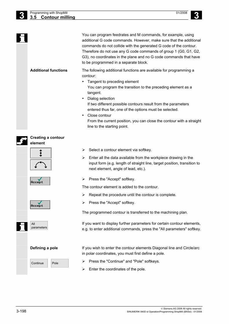
3 Programming with ShopMill 01/2008 3.5 Contour milling
3
© Siemens AG 2008 All rights reserved. 3-198 SINUMERIK 840D sl Operation/Programming ShopMill (BASsl) - 01/2008
You can program feedrates and M commands, for example, using additional G code commands. However, make sure that the additional commands do not collide with the generated G code of the contour. Therefore do not use any G code commands of group 1 (G0, G1, G2, G3), no coordinates in the plane and no G code commands that have to be programmed in a separate block.
Additional functions
The following additional functions are available for programming a contour: • Tangent to preceding element
You can program the transition to the preceding element as a tangent.
• Dialog selection If two different possible contours result from the parameters entered thus far, one of the options must be selected.
• Close contour From the current position, you can close the contour with a straight line to the starting point.
Creating a contour
element
Select a contour element via softkey.
Enter all the data available from the workpiece drawing in the input form (e.g. length of straight line, target position, transition to next element, angle of lead, etc.).
Press the "Accept" softkey.
The contour element is added to the contour.
Repeat the procedure until the contour is complete.
Press the "Accept" softkey.
The programmed contour is transferred to the machining plan.
All parameters
If you want to display further parameters for certain contour elements, e.g. to enter additional commands, press the "All parameters" softkey.
Defining a pole If you wish to enter the contour elements Diagonal line and Circle/arc in polar coordinates, you must first define a pole.
Continue
Pole
Press the "Continue" and "Pole" softkeys.
Enter the coordinates of the pole.
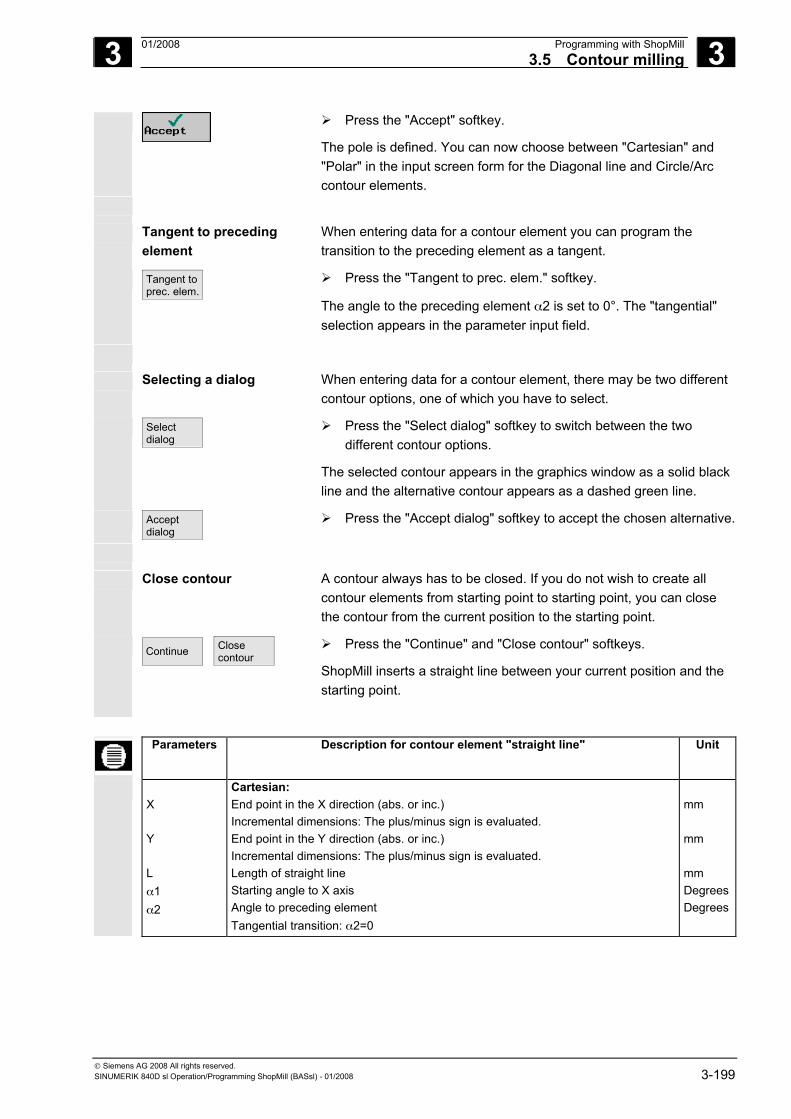
3 01/2008 Programming with ShopMill3.5 Contour milling
3
© Siemens AG 2008 All rights reserved. SINUMERIK 840D sl Operation/Programming ShopMill (BASsl) - 01/2008 3-199
Press the "Accept" softkey.
The pole is defined. You can now choose between "Cartesian" and "Polar" in the input screen form for the Diagonal line and Circle/Arc contour elements.
Tangent to preceding element
When entering data for a contour element you can program the transition to the preceding element as a tangent.
Tangent to prec. elem.
Press the "Tangent to prec. elem." softkey.
The angle to the preceding element α2 is set to 0°. The "tangential" selection appears in the parameter input field.
Selecting a dialog When entering data for a contour element, there may be two different contour options, one of which you have to select.
Select dialog
Press the "Select dialog" softkey to switch between the two different contour options.
The selected contour appears in the graphics window as a solid black line and the alternative contour appears as a dashed green line.
Accept dialog
Press the "Accept dialog" softkey to accept the chosen alternative.
Close contour
A contour always has to be closed. If you do not wish to create all contour elements from starting point to starting point, you can close the contour from the current position to the starting point.
Continue
Close contour
Press the "Continue" and "Close contour" softkeys.
ShopMill inserts a straight line between your current position and the starting point.
Parameters Description for contour element "straight line" Unit
X Y L α1 α2
Cartesian: End point in the X direction (abs. or inc.) Incremental dimensions: The plus/minus sign is evaluated. End point in the Y direction (abs. or inc.) Incremental dimensions: The plus/minus sign is evaluated. Length of straight line Starting angle to X axis Angle to preceding element Tangential transition: α2=0
mm mm mm Degrees Degrees
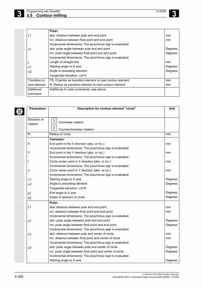
3 Programming with ShopMill 01/2008 3.5 Contour milling
3
© Siemens AG 2008 All rights reserved. 3-200 SINUMERIK 840D sl Operation/Programming ShopMill (BASsl) - 01/2008
L1 ϕ1 L α1 α2
Polar: abs: distance between pole and end point inc: distance between final point and end point Incremental dimensions: The plus/minus sign is evaluated. abs: polar angle between pole and end point inc: polar angle between final point and end point Incremental dimensions: The plus/minus sign is evaluated. Length of straight line Starting angle to X axis Angle to preceding element Tangential transition: α2=0
mm mm Degrees Degrees mm Degrees Degrees
Transition to next element
FS: Chamfer as transition element to next contour element R: Radius as transition element to next contour element
mm mm
Additional command
Additional G code commands; see above
Parameters Description for contour element "circle" Unit
Direction of rotation Clockwise rotation
Counterclockwise rotation
R Radius of circle mm
X Y I J α1 α2 β1 β2
Cartesian: End point in the X direction (abs. or inc.) Incremental dimensions: The plus/minus sign is evaluated. End point in the Y direction (abs. or inc.) Incremental dimensions: The plus/minus sign is evaluated. Circle center point in X direction (abs. or inc.) Incremental dimensions: The plus/minus sign is evaluated. Circle center point in Y direction (abs. or inc.) Incremental dimensions: The plus/minus sign is evaluated. Starting angle to X axis Angle to preceding element Tangential transition: α2=0 End angle to X axis Angle of aperture of circle
mm mm mm mm Degrees Degrees Degrees Degrees
L1 ϕ1 L2 ϕ2
Polar: abs: distance between pole and end point inc: distance between final point and end point Incremental dimensions: The plus/minus sign is evaluated. abs: polar angle between pole and end point inc: polar angle between final point and end point Incremental dimensions: The plus/minus sign is evaluated. abs: distance between pole and center of circle inc: distance between final point and center of circle Incremental dimensions: The plus/minus sign is evaluated. abs: polar angle between pole and center of circle inc: polar angle between final point and center of circle Incremental dimensions: The plus/minus sign is evaluated. Starting angle to X axis
mm mm Degrees Degrees mm mm Degrees Degrees Degrees
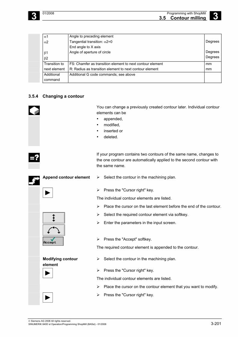
3 01/2008 Programming with ShopMill3.5 Contour milling
3
© Siemens AG 2008 All rights reserved. SINUMERIK 840D sl Operation/Programming ShopMill (BASsl) - 01/2008 3-201
α1 α2 β1 β2
Angle to preceding element Tangential transition: α2=0 End angle to X axis Angle of aperture of circle
Degrees Degrees Degrees
Transition to next element
FS: Chamfer as transition element to next contour element R: Radius as transition element to next contour element
mm mm
Additional command
Additional G code commands; see above
3.5.4 Changing a contour
You can change a previously created contour later. Individual contour elements can be • appended, • modified, • inserted or • deleted.
If your program contains two contours of the same name, changes to
the one contour are automatically applied to the second contour with the same name.
Append contour element
Select the contour in the machining plan.
Press the "Cursor right" key.
The individual contour elements are listed.
Place the cursor on the last element before the end of the contour.
Select the required contour element via softkey.
Enter the parameters in the input screen.
Press the "Accept" softkey.
The required contour element is appended to the contour.
Modifying contour element
Select the contour in the machining plan.
Press the "Cursor right" key.
The individual contour elements are listed.
Place the cursor on the contour element that you want to modify.
Press the "Cursor right" key.
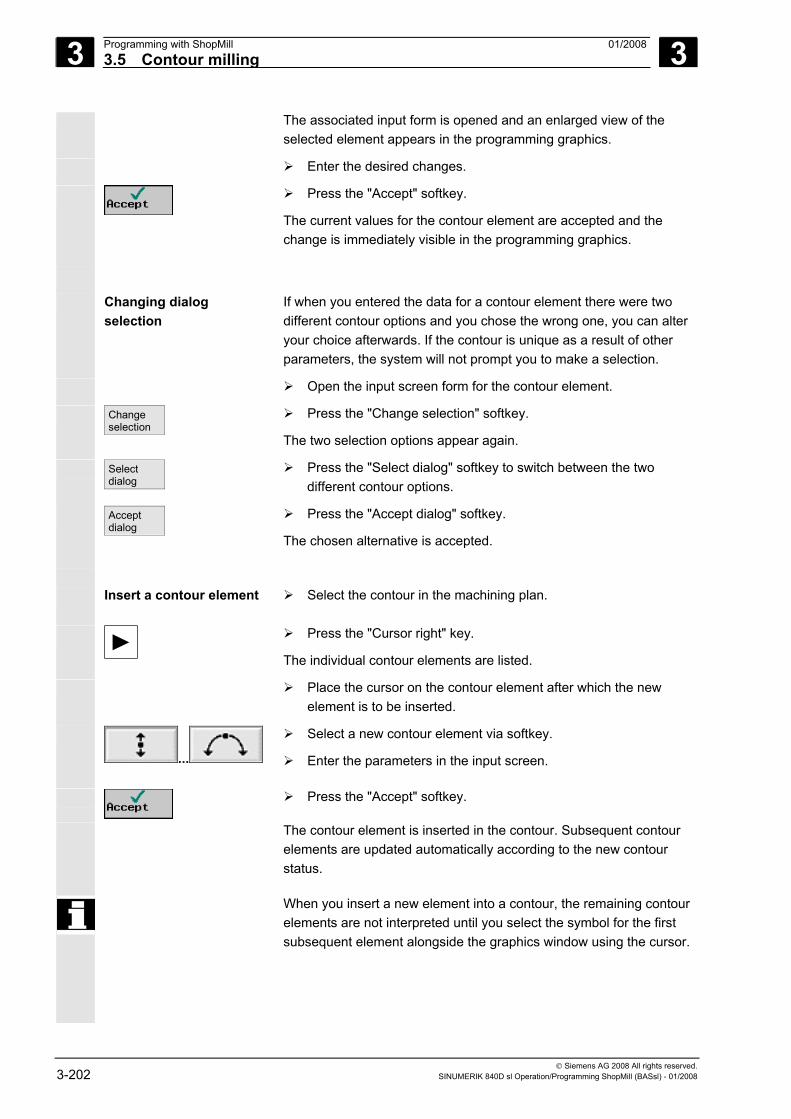
3 Programming with ShopMill 01/2008 3.5 Contour milling
3
© Siemens AG 2008 All rights reserved. 3-202 SINUMERIK 840D sl Operation/Programming ShopMill (BASsl) - 01/2008
The associated input form is opened and an enlarged view of the selected element appears in the programming graphics.
Enter the desired changes.
Press the "Accept" softkey.
The current values for the contour element are accepted and the change is immediately visible in the programming graphics.
Changing dialog selection
If when you entered the data for a contour element there were two different contour options and you chose the wrong one, you can alter your choice afterwards. If the contour is unique as a result of other parameters, the system will not prompt you to make a selection.
Open the input screen form for the contour element.
Change selection
Press the "Change selection" softkey.
The two selection options appear again.
Select dialog
Press the "Select dialog" softkey to switch between the two different contour options.
Accept dialog
Press the "Accept dialog" softkey.
The chosen alternative is accepted.
Insert a contour element
Select the contour in the machining plan.
Press the "Cursor right" key.
The individual contour elements are listed.
Place the cursor on the contour element after which the new element is to be inserted.
...
Select a new contour element via softkey.
Enter the parameters in the input screen.
Press the "Accept" softkey.
The contour element is inserted in the contour. Subsequent contour elements are updated automatically according to the new contour status.
When you insert a new element into a contour, the remaining contour elements are not interpreted until you select the symbol for the first subsequent element alongside the graphics window using the cursor.
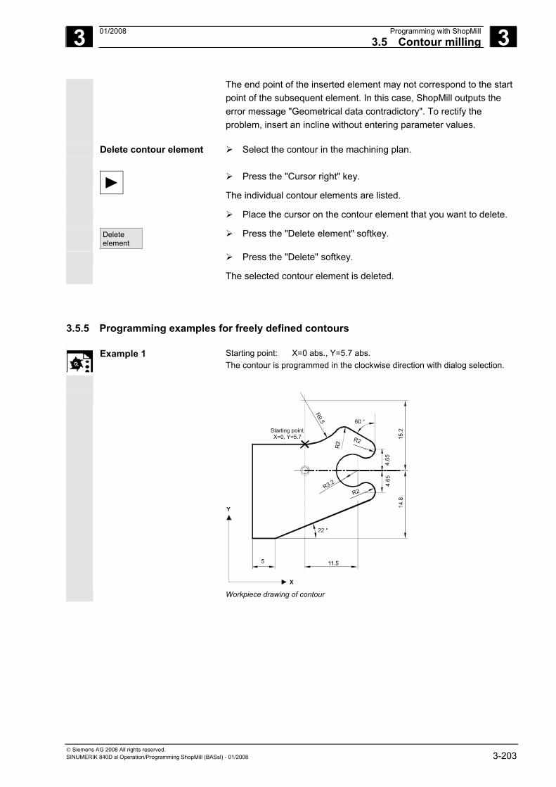
3 01/2008 Programming with ShopMill3.5 Contour milling
3
© Siemens AG 2008 All rights reserved. SINUMERIK 840D sl Operation/Programming ShopMill (BASsl) - 01/2008 3-203
The end point of the inserted element may not correspond to the start point of the subsequent element. In this case, ShopMill outputs the error message "Geometrical data contradictory". To rectify the problem, insert an incline without entering parameter values.
Delete contour element
Select the contour in the machining plan.
Press the "Cursor right" key.
The individual contour elements are listed.
Place the cursor on the contour element that you want to delete.
Delete element
Press the "Delete element" softkey.
Press the "Delete" softkey.
The selected contour element is deleted.
3.5.5 Programming examples for freely defined contours
Example 1 Starting point: X=0 abs., Y=5.7 abs. The contour is programmed in the clockwise direction with dialog selection.
X=0, Y=5.7
Y
X Workpiece drawing of contour
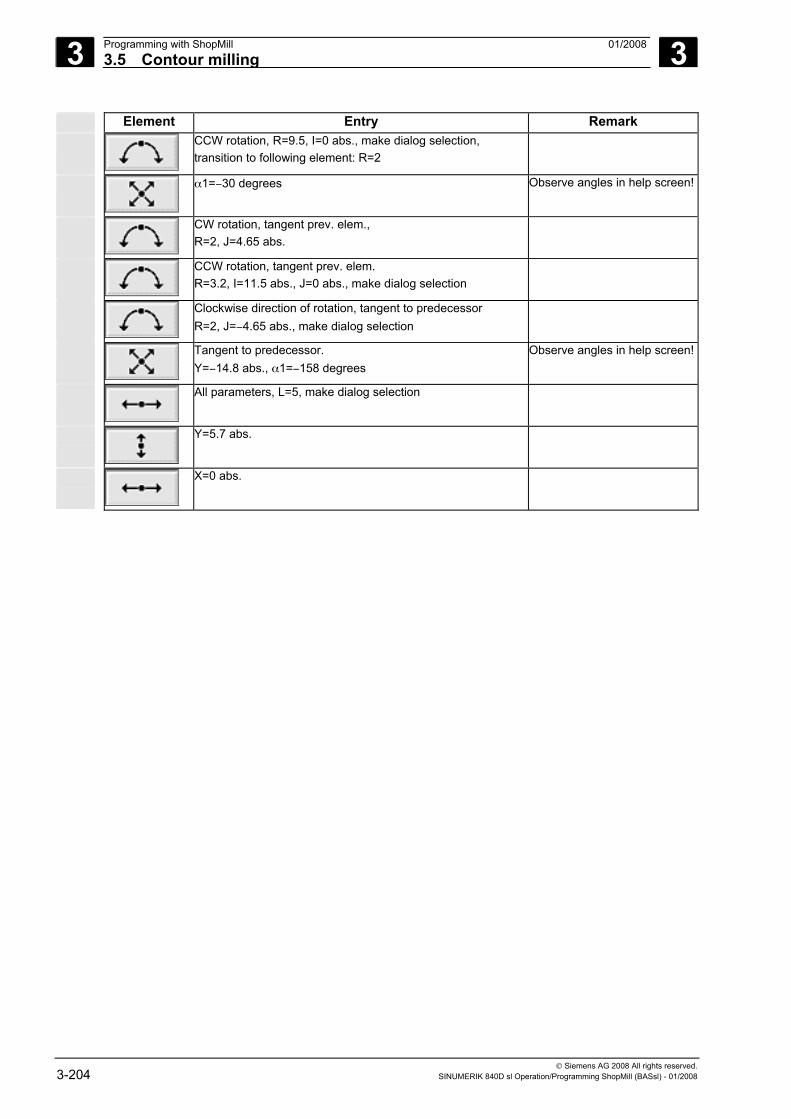
3 Programming with ShopMill 01/2008 3.5 Contour milling
3
© Siemens AG 2008 All rights reserved. 3-204 SINUMERIK 840D sl Operation/Programming ShopMill (BASsl) - 01/2008
Element Entry Remark
CCW rotation, R=9.5, I=0 abs., make dialog selection, transition to following element: R=2
α1=−30 degrees Observe angles in help screen!
CW rotation, tangent prev. elem., R=2, J=4.65 abs.
CCW rotation, tangent prev. elem. R=3.2, I=11.5 abs., J=0 abs., make dialog selection
Clockwise direction of rotation, tangent to predecessor R=2, J=−4.65 abs., make dialog selection
Tangent to predecessor. Y=−14.8 abs., α1=−158 degrees
Observe angles in help screen!
All parameters, L=5, make dialog selection
Y=5.7 abs.
X=0 abs.
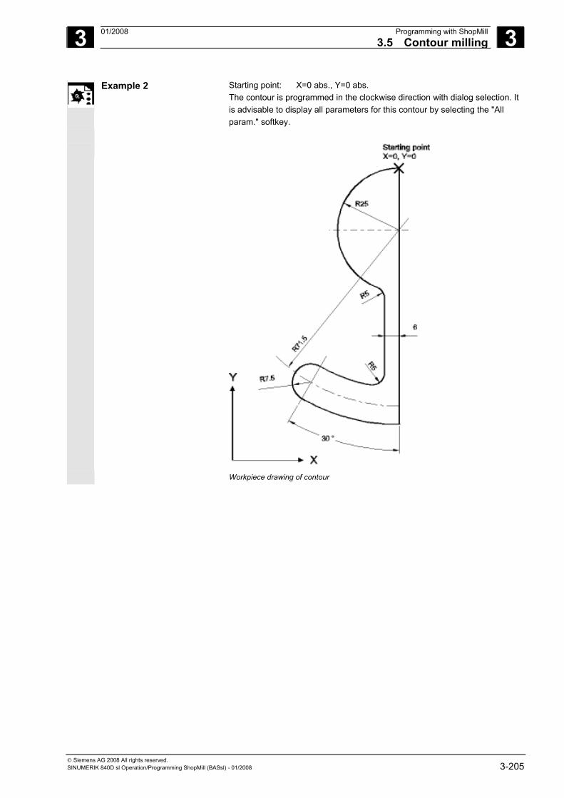
3 01/2008 Programming with ShopMill3.5 Contour milling
3
© Siemens AG 2008 All rights reserved. SINUMERIK 840D sl Operation/Programming ShopMill (BASsl) - 01/2008 3-205
Example 2 Starting point: X=0 abs., Y=0 abs. The contour is programmed in the clockwise direction with dialog selection. It is advisable to display all parameters for this contour by selecting the "All param." softkey.
Workpiece drawing of contour
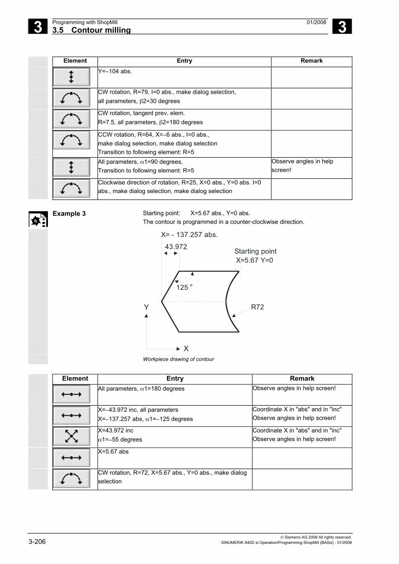
3 Programming with ShopMill 01/2008 3.5 Contour milling
3
© Siemens AG 2008 All rights reserved. 3-206 SINUMERIK 840D sl Operation/Programming ShopMill (BASsl) - 01/2008
Element Entry Remark
Y=−104 abs.
CW rotation, R=79, I=0 abs., make dialog selection, all parameters, β2=30 degrees
CW rotation, tangent prev. elem. R=7.5, all parameters, β2=180 degrees
CCW rotation, R=64, X=−6 abs., I=0 abs., make dialog selection, make dialog selection Transition to following element: R=5
All parameters, α1=90 degrees, Transition to following element: R=5
Observe angles in help screen!
Clockwise direction of rotation, R=25, X=0 abs., Y=0 abs. I=0 abs., make dialog selection, make dialog selection
Example 3 Starting point: X=5.67 abs., Y=0 abs.
The contour is programmed in a counter-clockwise direction.
X= - 137.257 abs.
X=5.67 Y=0
43.972
R72
125 °
Starting point
X
Y
Workpiece drawing of contour Element Entry Remark
All parameters, α1=180 degrees Observe angles in help screen!
X=−43.972 inc, all parameters X=−137.257 abs, α1=−125 degrees
Coordinate X in "abs" and in "inc" Observe angles in help screen!
X=43.972 inc α1=−55 degrees
Coordinate X in "abs" and in "inc" Observe angles in help screen!
X=5.67 abs
CW rotation, R=72, X=5.67 abs., Y=0 abs., make dialog selection
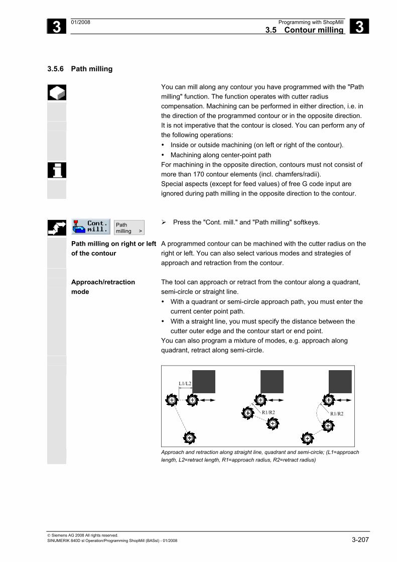
3 01/2008 Programming with ShopMill3.5 Contour milling
3
© Siemens AG 2008 All rights reserved. SINUMERIK 840D sl Operation/Programming ShopMill (BASsl) - 01/2008 3-207
3.5.6 Path milling
You can mill along any contour you have programmed with the "Path milling" function. The function operates with cutter radius compensation. Machining can be performed in either direction, i.e. in the direction of the programmed contour or in the opposite direction.
It is not imperative that the contour is closed. You can perform any of the following operations: • Inside or outside machining (on left or right of the contour). • Machining along center-point path
For machining in the opposite direction, contours must not consist of more than 170 contour elements (incl. chamfers/radii). Special aspects (except for feed values) of free G code input are ignored during path milling in the opposite direction to the contour.
Pathmilling >
Press the "Cont. mill." and "Path milling" softkeys.
Path milling on right or left of the contour
A programmed contour can be machined with the cutter radius on the right or left. You can also select various modes and strategies of approach and retraction from the contour.
Approach/retraction
mode The tool can approach or retract from the contour along a quadrant, semi-circle or straight line. • With a quadrant or semi-circle approach path, you must enter the
current center point path. • With a straight line, you must specify the distance between the
cutter outer edge and the contour start or end point. You can also program a mixture of modes, e.g. approach along quadrant, retract along semi-circle.
L1/L2
R1/R2R1/R2
Approach and retraction along straight line, quadrant and semi-circle; (L1=approach
length, L2=retract length, R1=approach radius, R2=retract radius)
3 Programming with ShopMill 01/2008 3.5 Contour milling
3
© Siemens AG 2008 All rights reserved. 3-208 SINUMERIK 840D sl Operation/Programming ShopMill (BASsl) - 01/2008
Approach/retraction strategy
You can choose between planar approach/retraction and spatial approach/retraction:
• Planar approach: Approach in Z direction to the depth
and then in the XY plane. • Spatial approach: Approach depth and plane
simultaneously • Retraction is performed in reverse order.
Mixed programming is possible, for example, approach in the plane, retract spatially.
Path milling along the center-point path
A programmed contour can also be machined along the center-point path if the operation has been activated under radius compensation
(no radius compensation). In this case, approaching and retraction is only possible along a straight line or vertical. Vertical approach/retraction can be used for closed contours, for example.
Parameters Description Unit
T, D, F, S, V See Section "Programming the tool, offset value and spindle speed".
Radius compensation
Machining to the left of the contour Machining to the right of the contour Machining along the center path
Machining method Roughing
Finishing Chamfering
Machining direction
Forward: machining is performed in the programmed contour direction Backward: machining is performed in the opposite direction to the programmed contour
Z0 Reference plane (abs. or inc.)
Z1 End depth (abs. or inc.) (not for chamfer) mm
DZ Infeed depth (not for chamfer) mm
FS Chamfer width (for chamfer only), inc. mm
ZFS Insertion depth tool tip (for chamfer only), abs. or inc. mm
UZ Finishing allowance base (not for chamfer) mm
3 01/2008 Programming with ShopMill3.5 Contour milling
3
© Siemens AG 2008 All rights reserved. SINUMERIK 840D sl Operation/Programming ShopMill (BASsl) - 01/2008 3-209
UXY Finishing allowance on edge (not applicable to center-point path machining operations) (not for chamfer)
mm
Approach mode
Quadrant: Part of a spiral (only with path milling left and right of the contour) Semicircle: Part of a spiral (only with path milling left and right of the contour) Linear: Slope in space Perpendicular: Perpendicular to the path (only with path milling on the center path)
Approach strategy planar
spatial (not with perpendicular approach mode)
R1 or L1 Approach radius (only for path milling on left and right of contour), approach length mm
Retract mode Quadrant: Part of a spiral (only with path milling left and right of the contour) Semicircle: Part of a spiral (only with path milling left and right of the contour) Linear: Slope in space Perpendicular: Perpendicular to the path (only with path milling on the center path)
Retract strategy planar
spatial (not with perpendicular approach mode)
R2 or L2 Retract radius (only for path milling on left and right of contour), retract length mm
Retraction mode
If more than one depth infeed is necessary, specify the retraction height to which the tool retracts between the separate infeeds (in the transition from the end of the contour to the beginning). Z0 + safety clearance Safety clearance To retraction plane No retraction
For cylinder surface transformation with selected slot side compensation and
approach/retraction in quadrant or semi-circle, the approach/retraction radius must be larger than “Offset to the programmed path – tool radius”.
3 Programming with ShopMill 01/2008 3.5 Contour milling
3
© Siemens AG 2008 All rights reserved. 3-210 SINUMERIK 840D sl Operation/Programming ShopMill (BASsl) - 01/2008
3.5.7 Predrilling a contour pocket
If a milling tool cannot be inserted in the center to remove stock from contour pockets, it is necessary to rough-drill first. The number and positions of the required rough drill holes depends on certain conditions, e.g. type of contour, tool, plane infeed, finishing allowances.
The rough-drilling cycle comprises a centering cycle and the actual rough-drilling cycle. The drilling positions in the contour pocket cycle are determined when the contour pocket is calculated. This calculation generates a special drilling program that is called in the rough drilling cycles (centering and rough drilling).
Contour pocket
Contour island
Rough drilling/centering contour pocket Rough drilling/rough drilling contour pocket Solid machining, roughing
Residual material
Solid machining, finishing plane
Solid machining, finishing depth
Example of a chain containing rough drilling (centering and rough drilling) and solid machining
If you mill several pockets and want to avoid unnecessary tool changeover, predrill all the pockets first and then remove the stock. In this case, for centering/predrilling, you also have to enter the parameters that appear when you press the "All parameters" softkey. These parameters must correspond to the parameters from the previous removal step. Then program as follows:
1. Contour pocket 1 2. Centering 3. Contour pocket 2 4. Centering 5. Contour pocket 1 6. Predrilling 7. Contour pocket 2 8. Predrilling 9. Contour pocket 1 10. Machining 11. Contour pocket 2 12. Machining
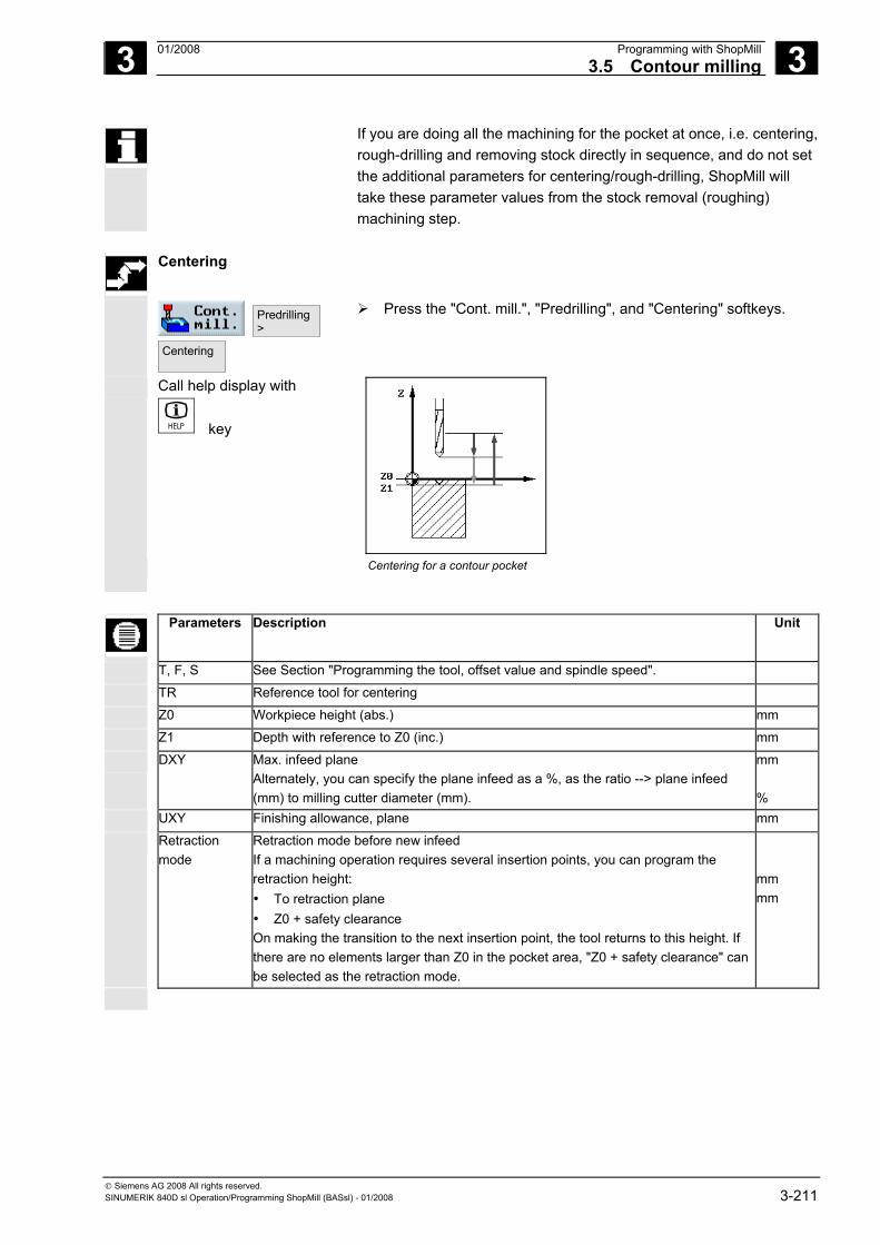
3 01/2008 Programming with ShopMill3.5 Contour milling
3
© Siemens AG 2008 All rights reserved. SINUMERIK 840D sl Operation/Programming ShopMill (BASsl) - 01/2008 3-211
If you are doing all the machining for the pocket at once, i.e. centering, rough-drilling and removing stock directly in sequence, and do not set the additional parameters for centering/rough-drilling, ShopMill will take these parameter values from the stock removal (roughing) machining step.
Centering
Predrilling >
Centering
Press the "Cont. mill.", "Predrilling", and "Centering" softkeys.
Call help display with
key
Centering for a contour pocket
Parameters Description Unit
T, F, S See Section "Programming the tool, offset value and spindle speed".
TR Reference tool for centering
Z0 Workpiece height (abs.) mm
Z1 Depth with reference to Z0 (inc.) mm
DXY Max. infeed plane Alternately, you can specify the plane infeed as a %, as the ratio --> plane infeed (mm) to milling cutter diameter (mm).
mm %
UXY Finishing allowance, plane mm
Retraction mode
Retraction mode before new infeed If a machining operation requires several insertion points, you can program the retraction height: • To retraction plane • Z0 + safety clearance On making the transition to the next insertion point, the tool returns to this height. If there are no elements larger than Z0 in the pocket area, "Z0 + safety clearance" can be selected as the retraction mode.
mm mm
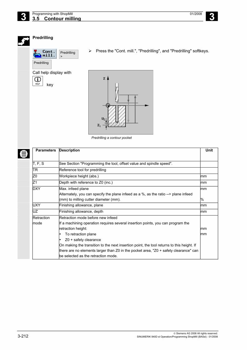
3 Programming with ShopMill 01/2008 3.5 Contour milling
3
© Siemens AG 2008 All rights reserved. 3-212 SINUMERIK 840D sl Operation/Programming ShopMill (BASsl) - 01/2008
Predrilling
Predrilling >
Predrilling
Press the "Cont. mill.", "Predrilling", and "Predrilling" softkeys.
Call help display with
key
Predrilling a contour pocket
Parameters Description Unit
T, F, S See Section "Programming the tool, offset value and spindle speed".
TR Reference tool for predrilling
Z0 Workpiece height (abs.) mm
Z1 Depth with reference to Z0 (inc.) mm
DXY Max. infeed plane Alternately, you can specify the plane infeed as a %, as the ratio --> plane infeed (mm) to milling cutter diameter (mm).
mm %
UXY Finishing allowance, plane mm
UZ Finishing allowance, depth mm
Retraction mode
Retraction mode before new infeed If a machining operation requires several insertion points, you can program the retraction height: • To retraction plane • Z0 + safety clearance On making the transition to the next insertion point, the tool returns to this height. If there are no elements larger than Z0 in the pocket area, "Z0 + safety clearance" can be selected as the retraction mode.
mm mm
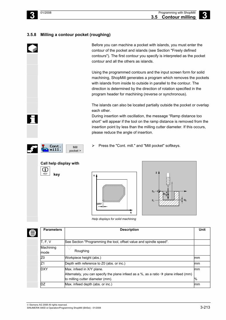
3 01/2008 Programming with ShopMill3.5 Contour milling
3
© Siemens AG 2008 All rights reserved. SINUMERIK 840D sl Operation/Programming ShopMill (BASsl) - 01/2008 3-213
3.5.8 Milling a contour pocket (roughing)
Before you can machine a pocket with islands, you must enter the contour of the pocket and islands (see Section "Freely defined contours"). The first contour you specify is interpreted as the pocket contour and all the others as islands.
Using the programmed contours and the input screen form for solid
machining, ShopMill generates a program which removes the pockets with islands from inside to outside in parallel to the contour. The direction is determined by the direction of rotation specified in the program header for machining (reverse or synchronous).
The islands can also be located partially outside the pocket or overlap
each other. During insertion with oscillation, the message “Ramp distance too
short” will appear if the tool on the ramp distance is removed from the insertion point by less than the milling cutter diameter. If this occurs, please reduce the angle of insertion.
Mill
pocket > Press the "Cont. mill." and "Mill pocket" softkeys.
Call help display with
key
Help displays for solid machining
Parameters Description Unit
T, F, V See Section "Programming the tool, offset value and spindle speed".
Machining mode Roughing
Z0 Workpiece height (abs.) mm
Z1 Depth with reference to Z0 (abs. or inc.) mm
DXY Max. infeed in X/Y plane. Alternately, you can specify the plane infeed as a %, as a ratio plane infeed (mm) to milling cutter diameter (mm).
mm %
DZ Max. infeed depth (abs. or inc.) mm
3 Programming with ShopMill 01/2008 3.5 Contour milling
3
© Siemens AG 2008 All rights reserved. 3-214 SINUMERIK 840D sl Operation/Programming ShopMill (BASsl) - 01/2008
UXY Finishing allowance, plane mm
ZU Finishing allowance, depth mm
Starting point The starting point can be determined automatically or entered manually.
X Y
Starting point X (abs.), manual input only Starting point Y (abs.), manual input only
mm mm
Insertion Oscillating: The tool is inserted oscillating with the program. angle (EW). Helical: The tool is inserted along a helical path with the programmed radius (ER) and programmed pitch (EP). Center: For this insertion strategy, a milling cutter is required that cuts in the center. The programmed feedrate(FZ) is used.
EW Insertion angle (for oscillation only) Degrees FZ Feedrate FZ (for Center only) mm/min
EP Insertion gradient (only for helical) The gradient of the helix may be smaller in some geometric conditions.
mm/rev
ER Insertion radius (only for helical) The radius must not be larger than the cutter radius, otherwise material will remain. Also make sure the pocket is not violated.
mm
Retraction mode
If the machining operation requires several points of insertion, the retraction height must be programmed: • To retraction plane • Z0 + safety clearance (SC)
On making the transition to the next insertion point, the tool returns to this height. If no elements greater than Z0 are in the pocket area, Z0 + safety clearance (SC) can be programmed as the retraction mode.
mm mm
When input manually, the starting point can also be located outside the pocket. This
can be useful, for example, when machining a pocket which is open on one side. The machining operation then begins without insertion with a linear movement into the open side of the pocket.
3 01/2008 Programming with ShopMill3.5 Contour milling
3
© Siemens AG 2008 All rights reserved. SINUMERIK 840D sl Operation/Programming ShopMill (BASsl) - 01/2008 3-215
3.5.9 Removing residual material from a contour pocket
If you have removed stock in a pocket (with/without islands) and residual material still remains, ShopMill will detect this automatically. You can use a suitable tool to remove this residual material without having to machine the whole pocket again, i.e. avoiding unnecessary idle motions. Material that remains as part of the finishing allowance is not residual material.
The residual material is calculated on the basis of the milling cutter
used for stock removal.
If you mill several pockets and want to avoid unnecessary tool changeover, remove stock from all the pockets first and then remove the residual material. In this case, for removing the residual material, you also have to enter a value for the "Reference tool TR" parameter that appears when you press the "All parameters" softkey. Then program as follows:
1. Contour pocket 1 2. Machining 3. Contour pocket 2 4. Machining 5. Contour pocket 1 6. Solid machine residual material 7. Contour pocket 2 8. Solid machine residual material
The "Residual material" function is a software option.
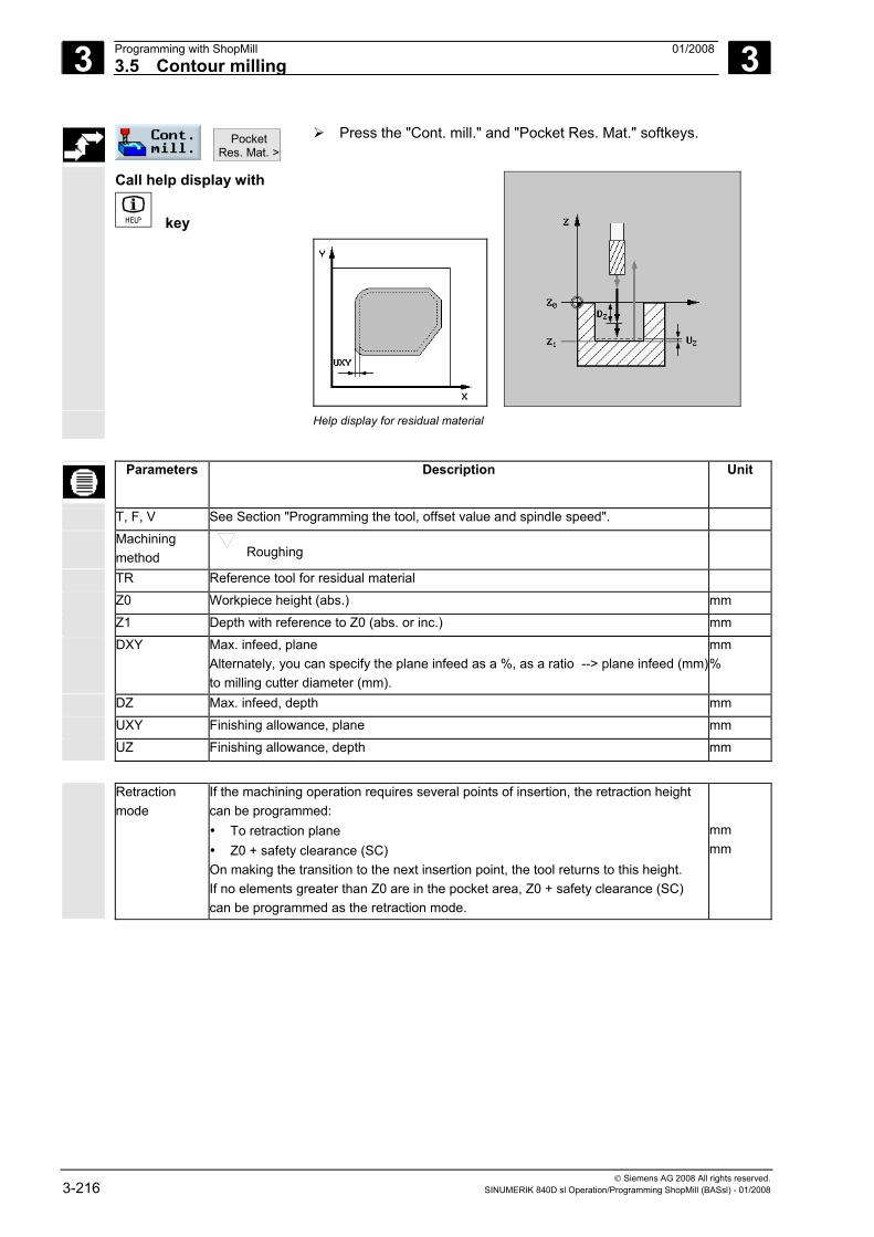
3 Programming with ShopMill 01/2008 3.5 Contour milling
3
© Siemens AG 2008 All rights reserved. 3-216 SINUMERIK 840D sl Operation/Programming ShopMill (BASsl) - 01/2008
Pocket Res. Mat. >
Press the "Cont. mill." and "Pocket Res. Mat." softkeys.
Call help display with
key
Help display for residual material
Parameters Description Unit
T, F, V See Section "Programming the tool, offset value and spindle speed".
Machining method Roughing
TR Reference tool for residual material
Z0 Workpiece height (abs.) mm
Z1 Depth with reference to Z0 (abs. or inc.) mm
DXY Max. infeed, plane Alternately, you can specify the plane infeed as a %, as a ratio --> plane infeed (mm) to milling cutter diameter (mm).
mm %
DZ Max. infeed, depth mm
UXY Finishing allowance, plane mm
UZ Finishing allowance, depth mm
Retraction
mode If the machining operation requires several points of insertion, the retraction height can be programmed: • To retraction plane • Z0 + safety clearance (SC) On making the transition to the next insertion point, the tool returns to this height. If no elements greater than Z0 are in the pocket area, Z0 + safety clearance (SC) can be programmed as the retraction mode.
mm mm
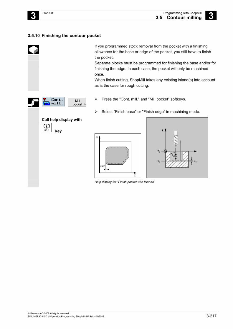
3 01/2008 Programming with ShopMill3.5 Contour milling
3
© Siemens AG 2008 All rights reserved. SINUMERIK 840D sl Operation/Programming ShopMill (BASsl) - 01/2008 3-217
3.5.10 Finishing the contour pocket
If you programmed stock removal from the pocket with a finishing allowance for the base or edge of the pocket, you still have to finish the pocket.
Separate blocks must be programmed for finishing the base and/or for finishing the edge. In each case, the pocket will only be machined once. When finish cutting, ShopMill takes any existing island(s) into account as is the case for rough cutting.
Mill
pocket > Press the "Cont. mill." and "Mill pocket" softkeys.
Select "Finish base" or "Finish edge" in machining mode.
Call help display with
key
Help display for "Finish pocket with islands"
3 Programming with ShopMill 01/2008 3.5 Contour milling
3
© Siemens AG 2008 All rights reserved. 3-218 SINUMERIK 840D sl Operation/Programming ShopMill (BASsl) - 01/2008
Parameters Description of finish cut along base: Unit
T, F, V See Section "Programming the tool, offset value and spindle speed".
Machining method
Base finishing
Z0 Workpiece height (abs.) mm
Z1 Depth with reference to Z0 (abs. or inc.) mm
DXY Max. infeed, plane Alternately, you can specify the plane infeed as a %, as a ratio --> plane infeed (mm) to milling cutter diameter (mm).
mm %
UXY Finishing allowance, plane mm
UZ Finishing allowance, depth mm
Starting point The starting point can be determined automatically or entered manually. Manual entry allows for a start point outside the pocket, whereby straight line machining into the pocket is performed first, e.g. for a pocket with a side opening without any insertion.
X Y
Coordinate of starting point (abs.), manual input only Coordinate of starting point (abs.), manual input only
mm mm
Insertion Oscillating: The tool is inserted at the programmed angle (EW). Helical: The tool is inserted along a helical path with the programmed radius (ER) and programmed pitch (EP). Center: For this insertion strategy, a milling cutter is required that cuts in the center. The programmed feedrate (FZ) is used.
EW Insertion angle (for oscillation only) Degrees EP Insertion gradient (only for helical)
The gradient of the helix may be smaller in some geometric conditions. mm/rev
ER Insertion radius (only for helical) The radius must not be larger than the cutter radius, otherwise material will remain. Also make sure the pocket is not violated.
mm
FZ Feedrate FZ (for Center only) mm/min
Retraction mode
If the machining operation requires several points of insertion, the retraction height can be programmed: • To retraction plane • Z0 + safety clearance (SC) On making the transition to the next insertion point, the tool returns to this height. If no elements greater than Z0 are in the pocket area, Z0 + safety clearance (SC) can be programmed as the retraction mode.
mm mm
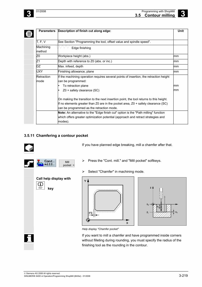
3 01/2008 Programming with ShopMill3.5 Contour milling
3
© Siemens AG 2008 All rights reserved. SINUMERIK 840D sl Operation/Programming ShopMill (BASsl) - 01/2008 3-219
Parameters Description of finish cut along edge: Unit
T, F, V See Section "Programming the tool, offset value and spindle speed".
Machining method
Edge finishing
Z0 Workpiece height (abs.) mm
Z1 Depth with reference to Z0 (abs. or inc.) mm
DZ Max. infeed, depth mm
UXY Finishing allowance, plane mm
Retraction mode
If the machining operation requires several points of insertion, the retraction height can be programmed: • To retraction plane • Z0 + safety clearance (SC) On making the transition to the next insertion point, the tool returns to this height. If no elements greater than Z0 are in the pocket area, Z0 + safety clearance (SC) can be programmed as the retraction mode.
mm mm
Note: An alternative to the "Edge finish cut" option is the "Path milling" function which offers greater optimization potential (approach and retract strategies and modes).
3.5.11 Chamfering a contour pocket
If you have planned edge breaking, mill a chamfer after that.
Mill
pocket > Press the "Cont. mill." and "Mill pocket" softkeys.
Select "Chamfer" in machining mode.
Call help display with
key
Help display "Chamfer pocket"
If you want to mill a chamfer and have programmed inside corners without filleting during rounding, you must specify the radius of the finishing tool as the rounding in the contour.
3 Programming with ShopMill 01/2008 3.5 Contour milling
3
© Siemens AG 2008 All rights reserved. 3-220 SINUMERIK 840D sl Operation/Programming ShopMill (BASsl) - 01/2008
Parameters Description for chamfer: Unit
T, F, V See Section "Programming the tool, offset value and spindle speed".
Machining method
Chamfering
Z0 Workpiece height (abs.) mm
FS Chamfer width (for chamfer only), inc. mm
ZFS Insertion depth tool tip (for chamfer only), abs. or inc. mm
3.5.12 Milling a contour spigot (roughing)
Use the "Mill spigot" function if you want to mill any kind of spigot.
Before you mill the spigot, you must first enter a blank contour and
then one or more spigot contours. The blank contour defines the outer limits of the material. The tool moves at rapid traverse outside this area. Material is then removed between the blank contour and spigot contour.
You can select the machining mode (roughing or finishing) for milling. If you want to rough and then finish, you have to call the machining cycle twice (Block 1 = roughing, Block 2 = finishing). The programmed parameters are retained when the cycle is called for the second time. For more on finishing, see Section "Finishing the contour spigot".
If you only program a blank contour without a second contour for a spigot, you can face mill the blank contour.
Approach/retraction 1. The tool approaches the starting point at rapid traverse at the height of the retraction plane and adjusts to the safety distance. The start point is calculated by ShopMill.
2. The tool first infeeds to the machining depth and then approaches the spigot contour from the side in a quadrant at machining feedrate.
3. The spigot is cleared in parallel with the contours from the outside in. The direction is determined by the machining direction (climb/conventional) (see "Creating a new program; defining a blank").
4. When the first plane of the spigot has been cleared, the tool retracts from the contour in a quadrant and then infeeds to the next machining depth.
5. The spigot is again approached in a quadrant and cleared in parallel with the contours from outside in.
6. Steps 4 and 5 are repeated until the programmed spigot depth is reached.
7. The tool moves back to the safety distance at rapid traverse.
3 01/2008 Programming with ShopMill3.5 Contour milling
3
© Siemens AG 2008 All rights reserved. SINUMERIK 840D sl Operation/Programming ShopMill (BASsl) - 01/2008 3-221
Mill spigot >
Press the "Cont. mill." and "Mill spigot" softkeys.
Select "Roughing" machining mode.
Parameters Description for roughing Unit
T, D, F, S, V See Section "Creating program blocks".
Machining protection Roughing
Z0 Z1 DXY DZ UXY UZ
Reference point in Z direction (abs.) Depth with reference to Z0 (abs. or inc.) Maximum infeed in the XY plane Plane infeed in %: Ratio of plane infeed (mm) to milling cutter diameter (mm) Maximum depth infeed (Z direction) Finishing allowance in plane Finishing allowance in depth
mm mm mm % mm mm mm
Retraction mode
If more than one approach point is necessary, specify the retraction height to which the tool retracts between approach points. • To retraction plane • Z0 + safety clearance
If there are no spigots or other elements larger than Z0 in the machining area, "Z0 + safety clearance" can be selected as the retraction mode.
3.5.13 Removing residual material from a contour spigot
When you have milled a contour spigot and residual material remains in place, this is automatically detected by ShopMill. You can use a suitable tool to remove this residual material without having to machine the whole spigot again, i.e. avoiding unnecessary idle motions. Material that remains as part of the finishing allowance is not residual material.
The residual material is calculated on the basis of the milling cutter
used for clearing.
If you mill several spigots and want to avoid unnecessary tool changeover, clear all the spigots first and then remove the residual material. In this case, for removing the residual material, you also have to enter a value for the "Reference tool TR" parameter that appears when you press the "All parameters" softkey. Then program as follows:
1. Contour blank 1 2. Contour spigot 1 3. Clear spigot 1 4. Contour blank 2
3 Programming with ShopMill 01/2008 3.5 Contour milling
3
© Siemens AG 2008 All rights reserved. 3-222 SINUMERIK 840D sl Operation/Programming ShopMill (BASsl) - 01/2008
5. Contour spigot 2 6. Clear spigot 2 7. Contour blank 1 8. Contour spigot 1 9. Clear residual material spigot 1 10. Contour blank 2 11. Contour spigot 2 12. Clear residual material spigot 2
The "Residual material" function is a software option.
Spigot Res.
Mat. > Press the "Cont. mill." and "Spigot Res. Mat." softkeys.
All parameters
Press the "All parameters" softkey if you want to enter additional parameters.
Parameters Description Unit
T, D, F, S, V See Section "Creating program blocks".
Machining method Roughing
TR Reference tool for residual material
D Cutting edge of reference tool (1 or 2)
Z0 Z1 DXY DZ UXY UZ
Reference point in Z direction (abs.) Depth with reference to Z0 (abs. or inc.) Maximum infeed in the XY plane Plane infeed in %: Ratio of plane infeed (mm) to milling cutter diameter (mm) Maximum depth infeed (Z direction) Finishing allowance in plane Finishing allowance in depth
mm mm mm % mm mm mm
Retraction mode
If more than one approach point is necessary, specify the retraction height to which the tool retracts between approach points. • To retraction plane • Z0 + safety clearance
If there are no spigots or other elements larger than Z0 in the machining area, "Z0 + safety clearance" can be selected as the retraction mode.
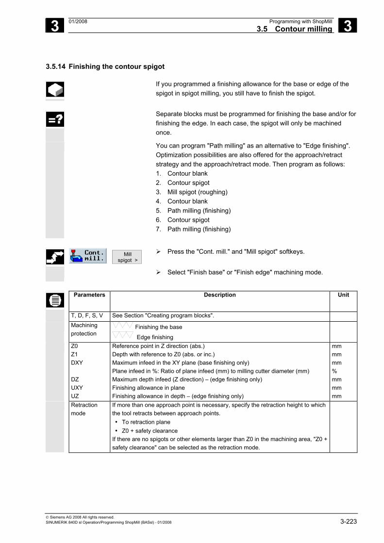
3 01/2008 Programming with ShopMill3.5 Contour milling
3
© Siemens AG 2008 All rights reserved. SINUMERIK 840D sl Operation/Programming ShopMill (BASsl) - 01/2008 3-223
3.5.14 Finishing the contour spigot
If you programmed a finishing allowance for the base or edge of the spigot in spigot milling, you still have to finish the spigot.
Separate blocks must be programmed for finishing the base and/or for
finishing the edge. In each case, the spigot will only be machined once.
You can program "Path milling" as an alternative to "Edge finishing". Optimization possibilities are also offered for the approach/retract strategy and the approach/retract mode. Then program as follows: 1. Contour blank 2. Contour spigot 3. Mill spigot (roughing) 4. Contour blank 5. Path milling (finishing) 6. Contour spigot 7. Path milling (finishing)
Mill
spigot > Press the "Cont. mill." and "Mill spigot" softkeys.
Select "Finish base" or "Finish edge" machining mode.
Parameters Description Unit
T, D, F, S, V See Section "Creating program blocks".
Machining protection
Finishing the base
Edge finishing
Z0 Z1 DXY DZ UXY UZ
Reference point in Z direction (abs.) Depth with reference to Z0 (abs. or inc.) Maximum infeed in the XY plane (base finishing only) Plane infeed in %: Ratio of plane infeed (mm) to milling cutter diameter (mm) Maximum depth infeed (Z direction) – (edge finishing only) Finishing allowance in plane Finishing allowance in depth – (edge finishing only)
mm mm mm % mm mm mm
Retraction mode
If more than one approach point is necessary, specify the retraction height to which the tool retracts between approach points. • To retraction plane • Z0 + safety clearance
If there are no spigots or other elements larger than Z0 in the machining area, "Z0 + safety clearance" can be selected as the retraction mode.
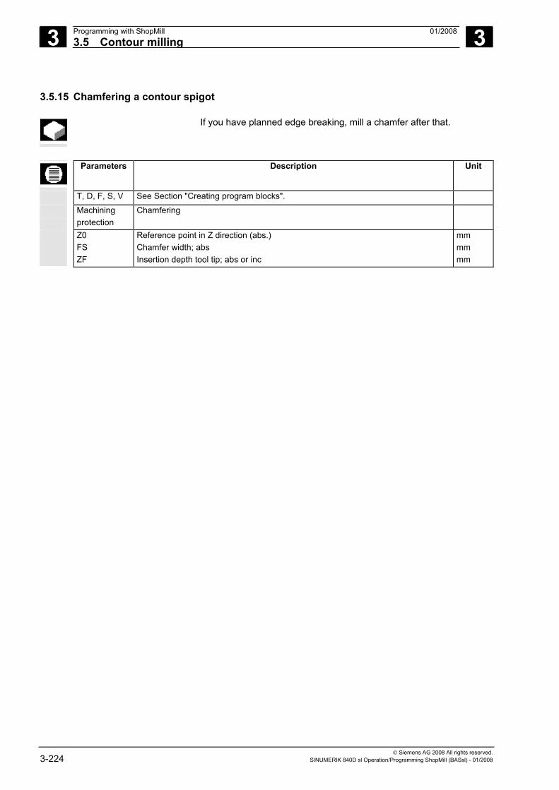
3 Programming with ShopMill 01/2008 3.5 Contour milling
3
© Siemens AG 2008 All rights reserved. 3-224 SINUMERIK 840D sl Operation/Programming ShopMill (BASsl) - 01/2008
3.5.15 Chamfering a contour spigot
If you have planned edge breaking, mill a chamfer after that.
Parameters Description Unit
T, D, F, S, V See Section "Creating program blocks".
Machining protection
Chamfering
Z0 FS ZF
Reference point in Z direction (abs.) Chamfer width; abs Insertion depth tool tip; abs or inc
mm mm mm
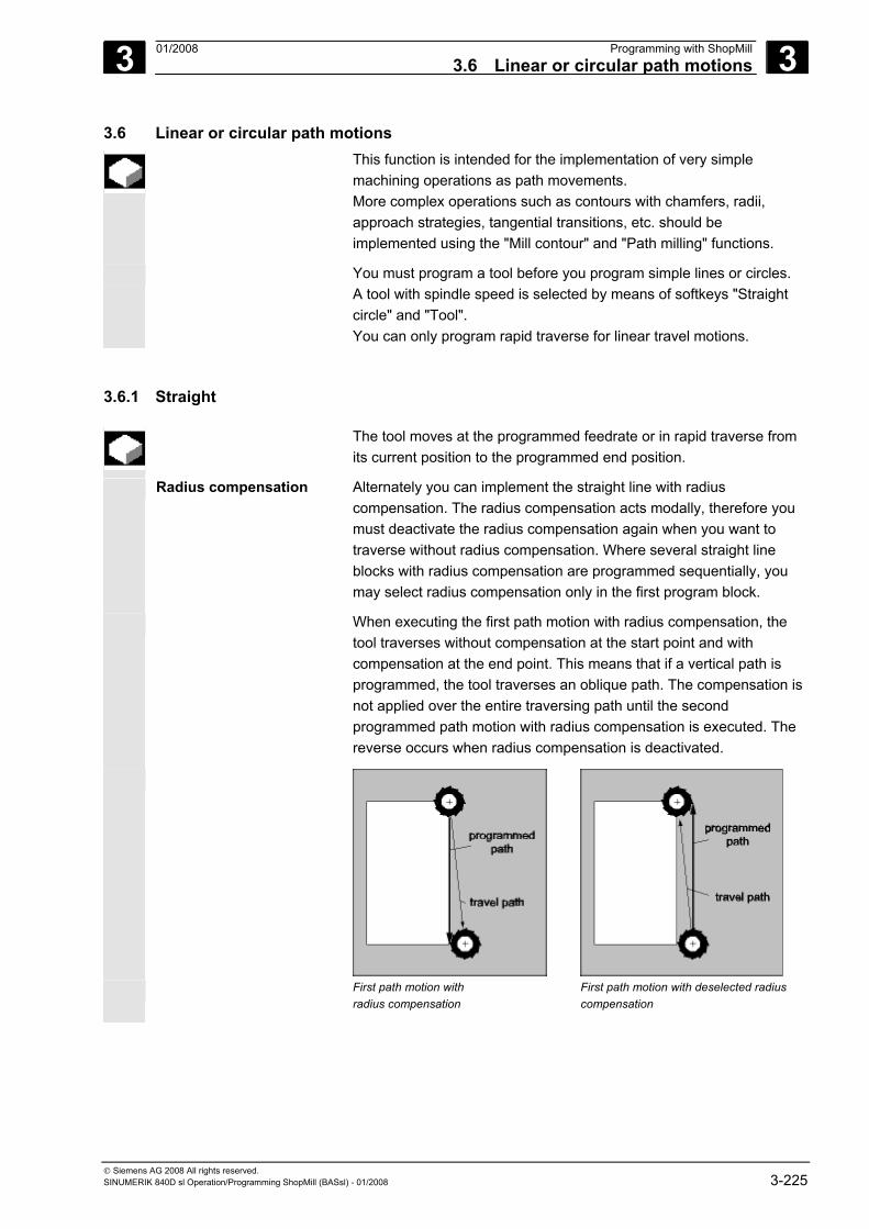
3 01/2008 Programming with ShopMill3.6 Linear or circular path motions
3
© Siemens AG 2008 All rights reserved. SINUMERIK 840D sl Operation/Programming ShopMill (BASsl) - 01/2008 3-225
3.6 Linear or circular path motions This function is intended for the implementation of very simple
machining operations as path movements. More complex operations such as contours with chamfers, radii, approach strategies, tangential transitions, etc. should be implemented using the "Mill contour" and "Path milling" functions.
You must program a tool before you program simple lines or circles. A tool with spindle speed is selected by means of softkeys "Straight circle" and "Tool". You can only program rapid traverse for linear travel motions.
3.6.1 Straight
The tool moves at the programmed feedrate or in rapid traverse from its current position to the programmed end position.
Radius compensation Alternately you can implement the straight line with radius compensation. The radius compensation acts modally, therefore you must deactivate the radius compensation again when you want to traverse without radius compensation. Where several straight line blocks with radius compensation are programmed sequentially, you may select radius compensation only in the first program block.
When executing the first path motion with radius compensation, the tool traverses without compensation at the start point and with compensation at the end point. This means that if a vertical path is programmed, the tool traverses an oblique path. The compensation is not applied over the entire traversing path until the second programmed path motion with radius compensation is executed. The reverse occurs when radius compensation is deactivated.
First path motion with
radius compensation First path motion with deselected radius compensation
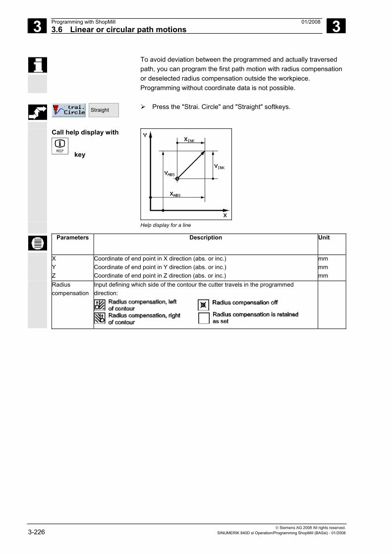
3 Programming with ShopMill 01/2008 3.6 Linear or circular path motions
3
© Siemens AG 2008 All rights reserved. 3-226 SINUMERIK 840D sl Operation/Programming ShopMill (BASsl) - 01/2008
To avoid deviation between the programmed and actually traversed path, you can program the first path motion with radius compensation or deselected radius compensation outside the workpiece. Programming without coordinate data is not possible.
Straight
Press the "Strai. Circle" and "Straight" softkeys.
Call help display with
key
Help display for a line
Parameters Description Unit
X Y Z
Coordinate of end point in X direction (abs. or inc.) Coordinate of end point in Y direction (abs. or inc.) Coordinate of end point in Z direction (abs. or inc.)
mm mm mm
Radius compensation
Input defining which side of the contour the cutter travels in the programmed direction:
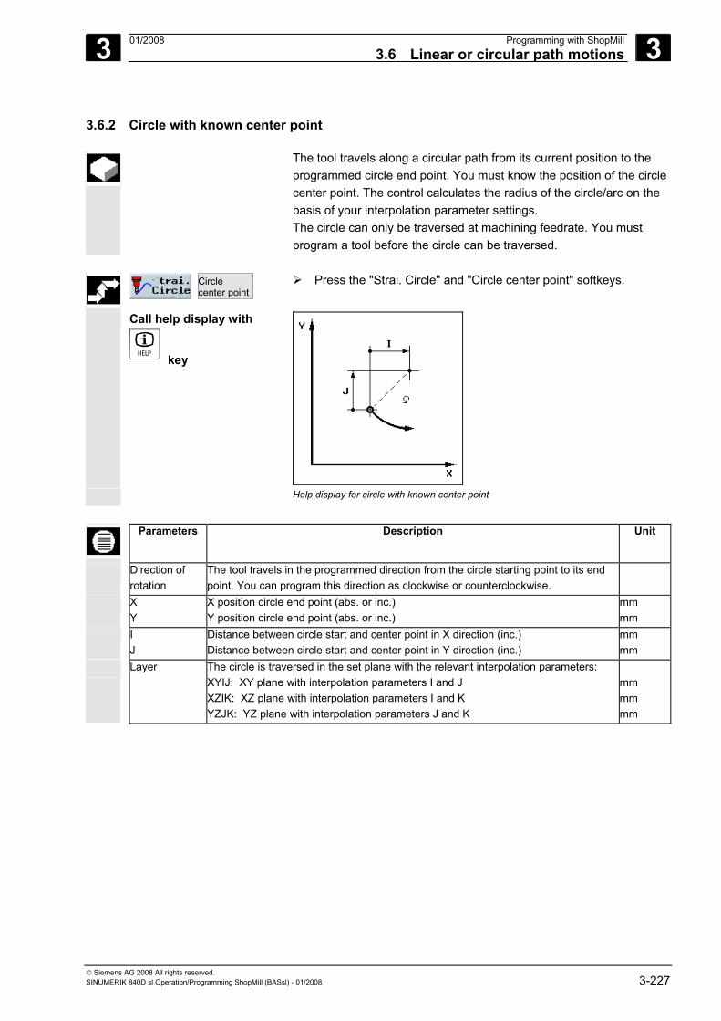
3 01/2008 Programming with ShopMill3.6 Linear or circular path motions
3
© Siemens AG 2008 All rights reserved. SINUMERIK 840D sl Operation/Programming ShopMill (BASsl) - 01/2008 3-227
3.6.2 Circle with known center point
The tool travels along a circular path from its current position to the programmed circle end point. You must know the position of the circle center point. The control calculates the radius of the circle/arc on the basis of your interpolation parameter settings. The circle can only be traversed at machining feedrate. You must program a tool before the circle can be traversed.
Circle center point
Press the "Strai. Circle" and "Circle center point" softkeys.
Call help display with
key
Help display for circle with known center point
Parameters Description Unit
Direction of rotation
The tool travels in the programmed direction from the circle starting point to its end point. You can program this direction as clockwise or counterclockwise.
X Y
X position circle end point (abs. or inc.) Y position circle end point (abs. or inc.)
mm mm
I J
Distance between circle start and center point in X direction (inc.) Distance between circle start and center point in Y direction (inc.)
mm mm
Layer The circle is traversed in the set plane with the relevant interpolation parameters: XYIJ: XY plane with interpolation parameters I and J XZIK: XZ plane with interpolation parameters I and K YZJK: YZ plane with interpolation parameters J and K
mm mm mm
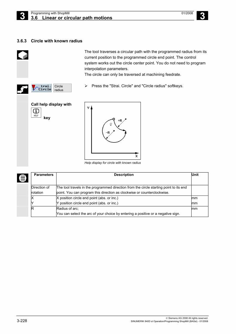
3 Programming with ShopMill 01/2008 3.6 Linear or circular path motions
3
© Siemens AG 2008 All rights reserved. 3-228 SINUMERIK 840D sl Operation/Programming ShopMill (BASsl) - 01/2008
3.6.3 Circle with known radius
The tool traverses a circular path with the programmed radius from its current position to the programmed circle end point. The control system works out the circle center point. You do not need to program interpolation parameters. The circle can only be traversed at machining feedrate.
Circle radius
Press the "Strai. Circle" and "Circle radius" softkeys.
Call help display with
key
Help display for circle with known radius
Parameters Description Unit
Direction of rotation
The tool travels in the programmed direction from the circle starting point to its end point. You can program this direction as clockwise or counterclockwise.
X Y
X position circle end point (abs. or inc.) Y position circle end point (abs. or inc.)
mm mm
R Radius of arc; You can select the arc of your choice by entering a positive or a negative sign.
mm
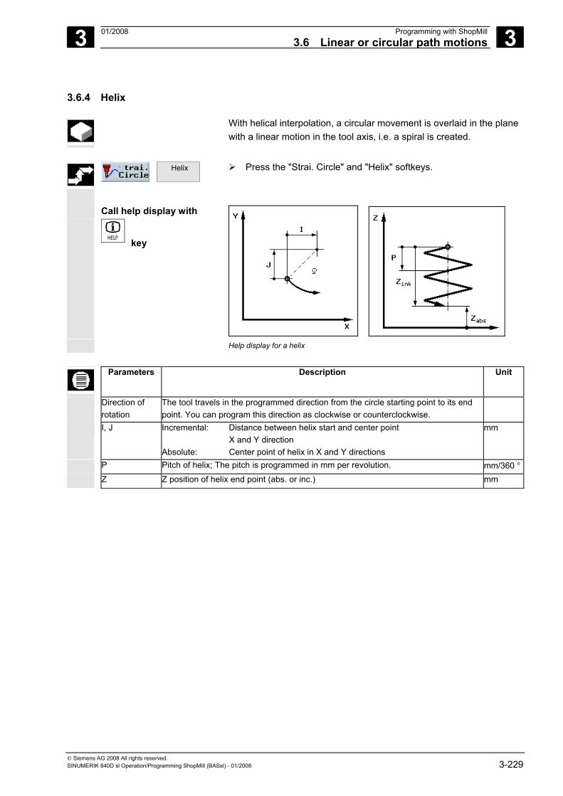
3 01/2008 Programming with ShopMill3.6 Linear or circular path motions
3
© Siemens AG 2008 All rights reserved. SINUMERIK 840D sl Operation/Programming ShopMill (BASsl) - 01/2008 3-229
3.6.4 Helix
With helical interpolation, a circular movement is overlaid in the plane with a linear motion in the tool axis, i.e. a spiral is created.
Helix
Press the "Strai. Circle" and "Helix" softkeys.
Call help display with
key
Help display for a helix
Parameters Description Unit
Direction of rotation
The tool travels in the programmed direction from the circle starting point to its end point. You can program this direction as clockwise or counterclockwise.
I, J Incremental: Distance between helix start and center point X and Y direction Absolute: Center point of helix in X and Y directions
mm
P Pitch of helix; The pitch is programmed in mm per revolution. mm/360 °
Z Z position of helix end point (abs. or inc.) mm
3 Programming with ShopMill 01/2008 3.6 Linear or circular path motions
3
© Siemens AG 2008 All rights reserved. 3-230 SINUMERIK 840D sl Operation/Programming ShopMill (BASsl) - 01/2008
3.6.5 Polar coordinates
If a workpiece has been dimensioned from a central point (pole) with radius and angles, you will find it helpful to program these as polar coordinates. You can program straight lines and circles as polar coordinates.
Defining a pole You must define the pole before you can program a line or circle in polar coordinates. This pole acts as the reference point of the polar coordinate system. The angle for the first line or circle then needs to be programmed in absolute coordinates. You can program the angles for any further lines and circles as either absolute or incremental coordinates.
Polar
> Pole
>
Press the "Strai. Circle", "Polar" and "Pole" softkeys.
Parameters Description Unit
X X position of the pole (abs. or inc.) mm
Y Y position of the pole (abs. or inc.) mm
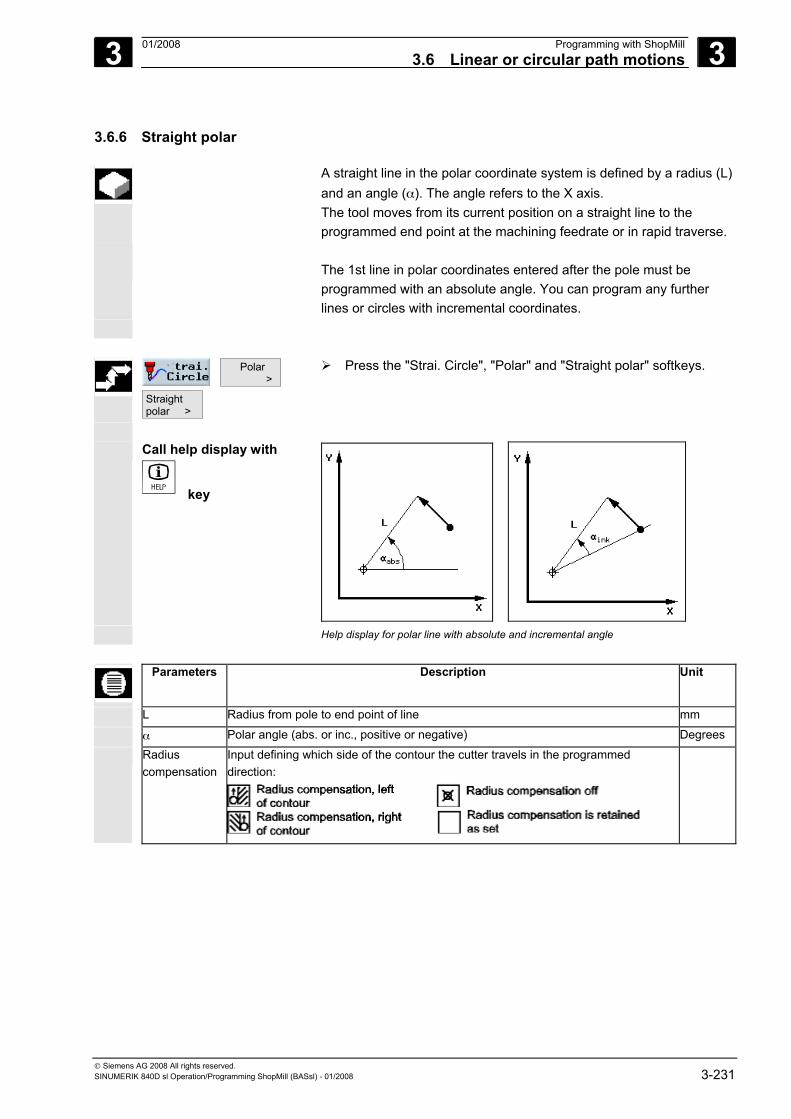
3 01/2008 Programming with ShopMill3.6 Linear or circular path motions
3
© Siemens AG 2008 All rights reserved. SINUMERIK 840D sl Operation/Programming ShopMill (BASsl) - 01/2008 3-231
3.6.6 Straight polar
A straight line in the polar coordinate system is defined by a radius (L) and an angle (α). The angle refers to the X axis. The tool moves from its current position on a straight line to the programmed end point at the machining feedrate or in rapid traverse.
The 1st line in polar coordinates entered after the pole must be
programmed with an absolute angle. You can program any further lines or circles with incremental coordinates.
Polar >
Straight polar >
Press the "Strai. Circle", "Polar" and "Straight polar" softkeys.
Call help display with
key
Help display for polar line with absolute and incremental angle
Parameters Description Unit
L Radius from pole to end point of line mm
α Polar angle (abs. or inc., positive or negative) Degrees Radius
compensation Input defining which side of the contour the cutter travels in the programmed direction:
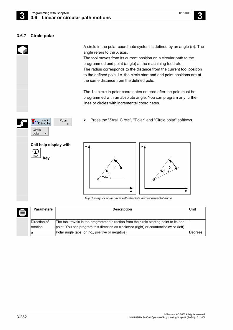
3 Programming with ShopMill 01/2008 3.6 Linear or circular path motions
3
© Siemens AG 2008 All rights reserved. 3-232 SINUMERIK 840D sl Operation/Programming ShopMill (BASsl) - 01/2008
3.6.7 Circle polar
A circle in the polar coordinate system is defined by an angle (α). The angle refers to the X axis. The tool moves from its current position on a circular path to the programmed end point (angle) at the machining feedrate. The radius corresponds to the distance from the current tool position to the defined pole, i.e. the circle start and end point positions are at the same distance from the defined pole.
The 1st circle in polar coordinates entered after the pole must be
programmed with an absolute angle. You can program any further lines or circles with incremental coordinates.
Polar >
Circle polar >
Press the "Strai. Circle", "Polar" and "Circle polar" softkeys.
Call help display with
key
Help display for polar circle with absolute and incremental angle
Parameters Description Unit
Direction of rotation
The tool travels in the programmed direction from the circle starting point to its end point. You can program this direction as clockwise (right) or counterclockwise (left).
α Polar angle (abs. or inc., positive or negative) Degrees
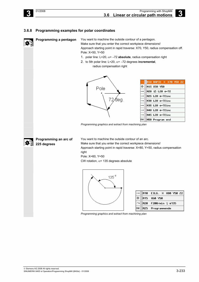
3 01/2008 Programming with ShopMill3.6 Linear or circular path motions
3
© Siemens AG 2008 All rights reserved. SINUMERIK 840D sl Operation/Programming ShopMill (BASsl) - 01/2008 3-233
3.6.8 Programming examples for polar coordinates
Programming a pentagon You want to machine the outside contour of a pentagon. Make sure that you enter the correct workpiece dimensions! Approach starting point in rapid traverse: X70, Y50, radius compensation off. Pole: X=50, Y=50 1. polar line: L=20, α= −72 absolute, radius compensation right 2. to 5th polar line: L=20, α= −72 degrees incremental, radius compensation right
Programming graphics and extract from machining plan
Programming an arc of 225 degrees
You want to machine the outside contour of an arc. Make sure that you enter the correct workpiece dimensions! Approach starting point in rapid traverse: X=80, Y=50, radius compensation right Pole: X=60, Y=50 CW rotation, α= 135 degrees absolute
Programming graphics and extract from machining plan
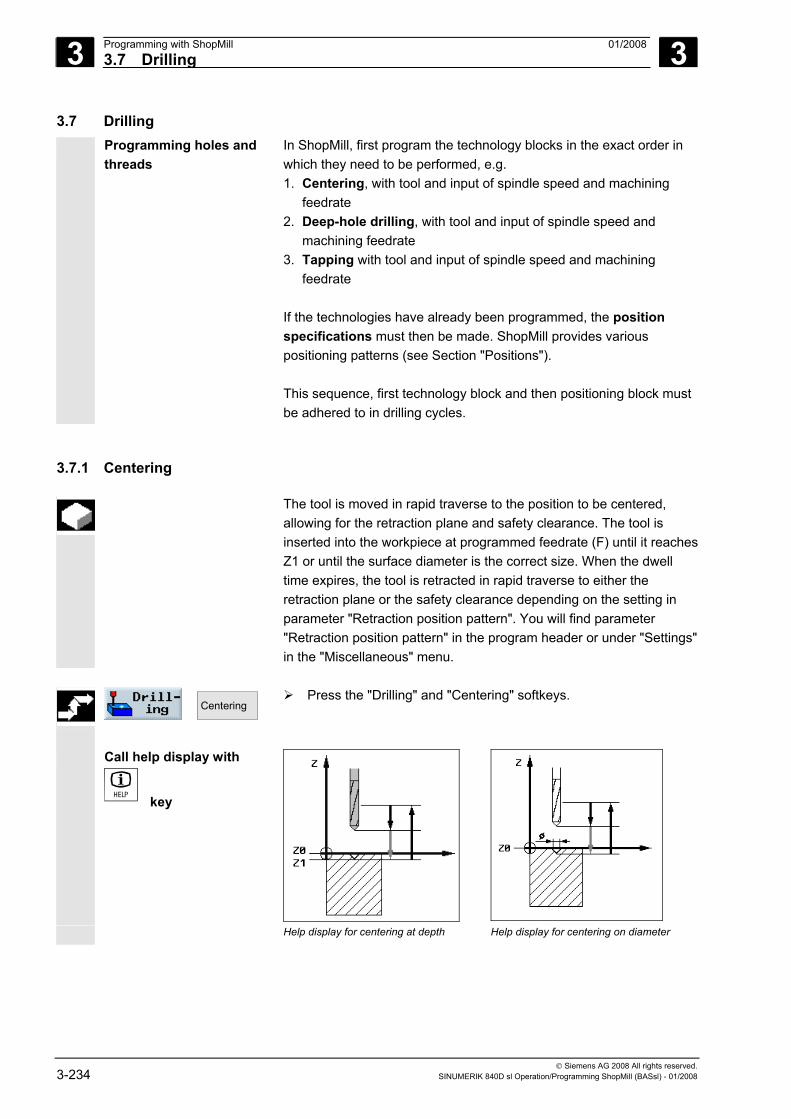
3 Programming with ShopMill 01/2008 3.7 Drilling
3
© Siemens AG 2008 All rights reserved. 3-234 SINUMERIK 840D sl Operation/Programming ShopMill (BASsl) - 01/2008
3.7 Drilling Programming holes and
threads In ShopMill, first program the technology blocks in the exact order in which they need to be performed, e.g. 1. Centering, with tool and input of spindle speed and machining
feedrate 2. Deep-hole drilling, with tool and input of spindle speed and
machining feedrate 3. Tapping with tool and input of spindle speed and machining
feedrate If the technologies have already been programmed, the position specifications must then be made. ShopMill provides various positioning patterns (see Section "Positions"). This sequence, first technology block and then positioning block must be adhered to in drilling cycles.
3.7.1 Centering
The tool is moved in rapid traverse to the position to be centered, allowing for the retraction plane and safety clearance. The tool is inserted into the workpiece at programmed feedrate (F) until it reachesZ1 or until the surface diameter is the correct size. When the dwell time expires, the tool is retracted in rapid traverse to either the retraction plane or the safety clearance depending on the setting in parameter "Retraction position pattern". You will find parameter "Retraction position pattern" in the program header or under "Settings" in the "Miscellaneous" menu.
Centering
Press the "Drilling" and "Centering" softkeys.
Call help display with
key
Help display for centering at depth Help display for centering on diameter
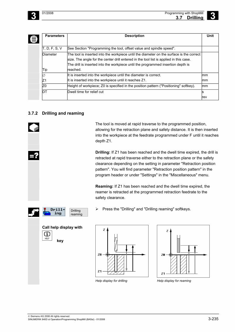
3 01/2008 Programming with ShopMill3.7 Drilling
3
© Siemens AG 2008 All rights reserved. SINUMERIK 840D sl Operation/Programming ShopMill (BASsl) - 01/2008 3-235
Parameters Description Unit
T, D, F, S, V See Section "Programming the tool, offset value and spindle speed".
Diameter Tip
The tool is inserted into the workpiece until the diameter on the surface is the correct size. The angle for the center drill entered in the tool list is applied in this case. The drill is inserted into the workpiece until the programmed insertion depth is reached.
∅ Z1
It is inserted into the workpiece until the diameter is correct. It is inserted into the workpiece until it reaches Z1.
mm mm
Z0 Height of workpiece; Z0 is specified in the position pattern ("Positioning" softkey). mm
DT Dwell time for relief cut s rev
3.7.2 Drilling and reaming
The tool is moved at rapid traverse to the programmed position, allowing for the retraction plane and safety distance. It is then inserted into the workpiece at the feedrate programmed under F until it reachesdepth Z1.
Drilling: If Z1 has been reached and the dwell time expired, the drill is
retracted at rapid traverse either to the retraction plane or the safety clearance depending on the setting in parameter "Retraction position pattern". You will find parameter "Retraction position pattern" in the program header or under "Settings" in the "Miscellaneous" menu.
Reaming: If Z1 has been reached and the dwell time expired, the
reamer is retracted at the programmed retraction feedrate to the safety clearance.
Drilling reaming
Press the "Drilling" and "Drilling reaming" softkeys.
Call help display with
key
Help display for drilling Help display for reaming
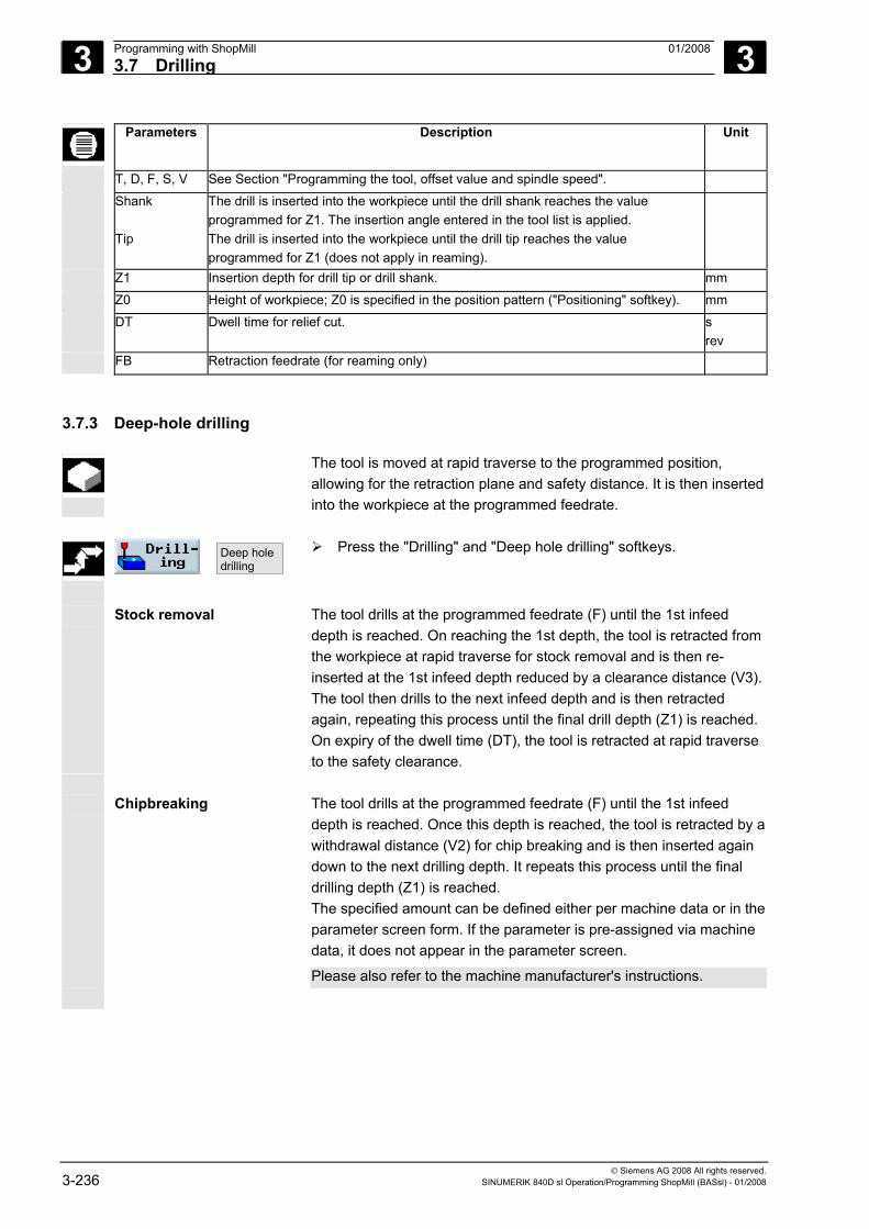
3 Programming with ShopMill 01/2008 3.7 Drilling
3
© Siemens AG 2008 All rights reserved. 3-236 SINUMERIK 840D sl Operation/Programming ShopMill (BASsl) - 01/2008
Parameters Description Unit
T, D, F, S, V See Section "Programming the tool, offset value and spindle speed".
Shank Tip
The drill is inserted into the workpiece until the drill shank reaches the value programmed for Z1. The insertion angle entered in the tool list is applied. The drill is inserted into the workpiece until the drill tip reaches the value programmed for Z1 (does not apply in reaming).
Z1 Insertion depth for drill tip or drill shank. mm
Z0 Height of workpiece; Z0 is specified in the position pattern ("Positioning" softkey). mm
DT Dwell time for relief cut. s rev
FB Retraction feedrate (for reaming only)
3.7.3 Deep-hole drilling
The tool is moved at rapid traverse to the programmed position, allowing for the retraction plane and safety distance. It is then inserted into the workpiece at the programmed feedrate.
Deep holedrilling
Press the "Drilling" and "Deep hole drilling" softkeys.
Stock removal
The tool drills at the programmed feedrate (F) until the 1st infeed depth is reached. On reaching the 1st depth, the tool is retracted from the workpiece at rapid traverse for stock removal and is then re-inserted at the 1st infeed depth reduced by a clearance distance (V3). The tool then drills to the next infeed depth and is then retracted again, repeating this process until the final drill depth (Z1) is reached. On expiry of the dwell time (DT), the tool is retracted at rapid traverse to the safety clearance.
Chipbreaking
The tool drills at the programmed feedrate (F) until the 1st infeed depth is reached. Once this depth is reached, the tool is retracted by a withdrawal distance (V2) for chip breaking and is then inserted again down to the next drilling depth. It repeats this process until the final drilling depth (Z1) is reached. The specified amount can be defined either per machine data or in the parameter screen form. If the parameter is pre-assigned via machine data, it does not appear in the parameter screen.
Please also refer to the machine manufacturer's instructions.
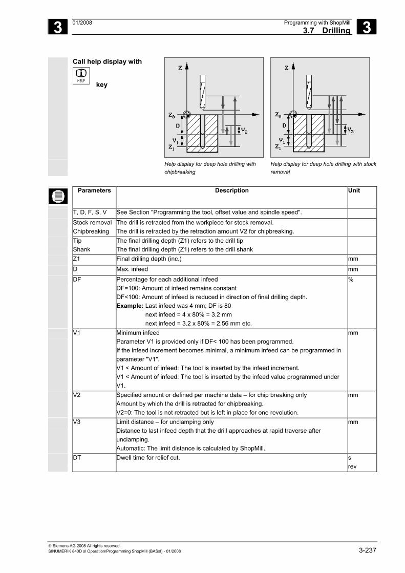
3 01/2008 Programming with ShopMill3.7 Drilling
3
© Siemens AG 2008 All rights reserved. SINUMERIK 840D sl Operation/Programming ShopMill (BASsl) - 01/2008 3-237
Call help display with
key
Help display for deep hole drilling with
chipbreaking Help display for deep hole drilling with stock removal
Parameters Description Unit
T, D, F, S, V See Section "Programming the tool, offset value and spindle speed".
Stock removal Chipbreaking
The drill is retracted from the workpiece for stock removal. The drill is retracted by the retraction amount V2 for chipbreaking.
Tip Shank
The final drilling depth (Z1) refers to the drill tip The final drilling depth (Z1) refers to the drill shank
Z1 Final drilling depth (inc.) mm
D Max. infeed mm
DF Percentage for each additional infeed DF=100: Amount of infeed remains constant DF<100: Amount of infeed is reduced in direction of final drilling depth. Example: Last infeed was 4 mm; DF is 80 next infeed = 4 x 80% = 3.2 mm next infeed = 3.2 x 80% = 2.56 mm etc.
%
V1 Minimum infeed Parameter V1 is provided only if DF< 100 has been programmed. If the infeed increment becomes minimal, a minimum infeed can be programmed in parameter "V1". V1 < Amount of infeed: The tool is inserted by the infeed increment. V1 < Amount of infeed: The tool is inserted by the infeed value programmed under V1.
mm
V2 Specified amount or defined per machine data – for chip breaking only Amount by which the drill is retracted for chipbreaking. V2=0: The tool is not retracted but is left in place for one revolution.
mm
V3 Limit distance – for unclamping only Distance to last infeed depth that the drill approaches at rapid traverse after unclamping. Automatic: The limit distance is calculated by ShopMill.
mm
DT Dwell time for relief cut. s rev
3 Programming with ShopMill 01/2008 3.7 Drilling
3
© Siemens AG 2008 All rights reserved. 3-238 SINUMERIK 840D sl Operation/Programming ShopMill (BASsl) - 01/2008
3.7.4 Boring
The tool is moved at rapid traverse to the programmed position, allowing for the retraction plane and safety distance. It is then inserted into the workpiece at the feedrate programmed under F until it reachesthe programmed depth (Z1). The spindle stops are a specific position there. "Lift off contour" or "Do not lift off contour" can be programmed on expiry of the dwell time.
With retraction, withdrawal distance D and the tool orientation angle α can either be defined via machine data or in the parameter screen. If both parameters are pre-assigned via machine data, they do not appear in the parameter screen.
Please also refer to the machine manufacturer's instructions.
Boring
Press the "Drilling" and "Boring" softkeys.
Call help display with
key
Help display for boring
Parameters Description Unit
T, D, F, S, V See Section "Programming the tool, offset value and spindle speed".
Lift off Do not lift off
The cutting edge is retracted from the bore edge and then moved back to the retraction plane. The cutting edge is not retracted, but traverses back to the safety clearance in rapid traverse.
Z1 Depth with reference to Z0 (abs. or inc.) mm
Z0 Height of workpiece; Z0 is specified in the position pattern ("Positioning" softkey). mm
DT Dwell time for relief cut. I rev
D Withdrawal (retract) distance (or defined in machine data) - only for retraction mm
α Tool orientation angle (or defined via machine data) - only for retraction Degrees
3 01/2008 Programming with ShopMill3.7 Drilling
3
© Siemens AG 2008 All rights reserved. SINUMERIK 840D sl Operation/Programming ShopMill (BASsl) - 01/2008 3-239
3.7.5 Tapping
The "Tapping" function is used for tapping an inside thread.
The spindle speed can be controlled with the spindle override during tapping. The feedrate override has no effect during this process.
You can select drilling in one cut, chipbreaking or retraction from the workpiece for stock removal.
The tool is moved at rapid traverse to the programmed position, allowing for the retraction plane and safety distance. While the spindle is stationary, the tool moves at rapid traverse to the retraction plane and then to the safety distance. At this point, the spindle begins to rotate and the spindle speed and feedrate are synchronized. The tool continues to move at rapid traverse towards the programmed position.
1 cut 1. The tool drills at the programmed spindle speed S or cut rate V as far as the tapping depth Z1.
2. The direction of rotation of the spindle reverses and the tool retracts to the safety distance at the programmed spindle speed SR or cut rate VR.
Stock removal
1. The tool drills at the programmed spindle speed S or feedrate V as far as the first infeed depth (maximum infeed depth D).
2. The tool retracts from the workpiece to the safety distance at spindle speed SR or cut rate VR for stock removal.
3. The then tool enters the workpiece again at spindle speed SR and feedrate VR to the 1st infeed depth with an anticipation point of 1 mm. The spindle speed changes to S and the feedrate to V, and the tool then drills to the next infeed depth.
4. Steps 2 and 3 are repeated until the programmed final drilling depth Z1 is reached.
5. The direction of rotation of the spindle reverses and the tool retracts to the safety distance at spindle speed SR or cut rate VR.
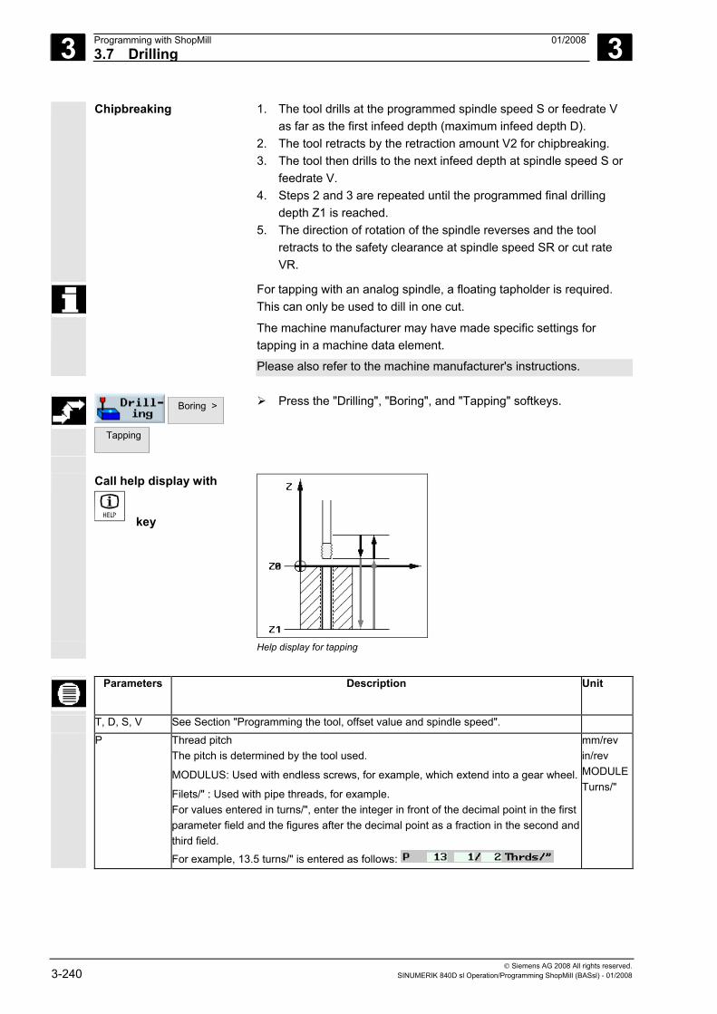
3 Programming with ShopMill 01/2008 3.7 Drilling
3
© Siemens AG 2008 All rights reserved. 3-240 SINUMERIK 840D sl Operation/Programming ShopMill (BASsl) - 01/2008
Chipbreaking
1. The tool drills at the programmed spindle speed S or feedrate V as far as the first infeed depth (maximum infeed depth D).
2. The tool retracts by the retraction amount V2 for chipbreaking. 3. The tool then drills to the next infeed depth at spindle speed S or
feedrate V. 4. Steps 2 and 3 are repeated until the programmed final drilling
depth Z1 is reached. 5. The direction of rotation of the spindle reverses and the tool
retracts to the safety clearance at spindle speed SR or cut rate VR.
For tapping with an analog spindle, a floating tapholder is required. This can only be used to dill in one cut.
The machine manufacturer may have made specific settings for tapping in a machine data element.
Please also refer to the machine manufacturer's instructions.
Boring >
Tapping
Press the "Drilling", "Boring", and "Tapping" softkeys.
Call help display with
key
Help display for tapping
Parameters Description Unit
T, D, S, V See Section "Programming the tool, offset value and spindle speed".
P Thread pitch The pitch is determined by the tool used.
MODULUS: Used with endless screws, for example, which extend into a gear wheel.
Filets/" : Used with pipe threads, for example. For values entered in turns/", enter the integer in front of the decimal point in the first parameter field and the figures after the decimal point as a fraction in the second and third field.
For example, 13.5 turns/" is entered as follows:
mm/rev in/rev MODULETurns/"
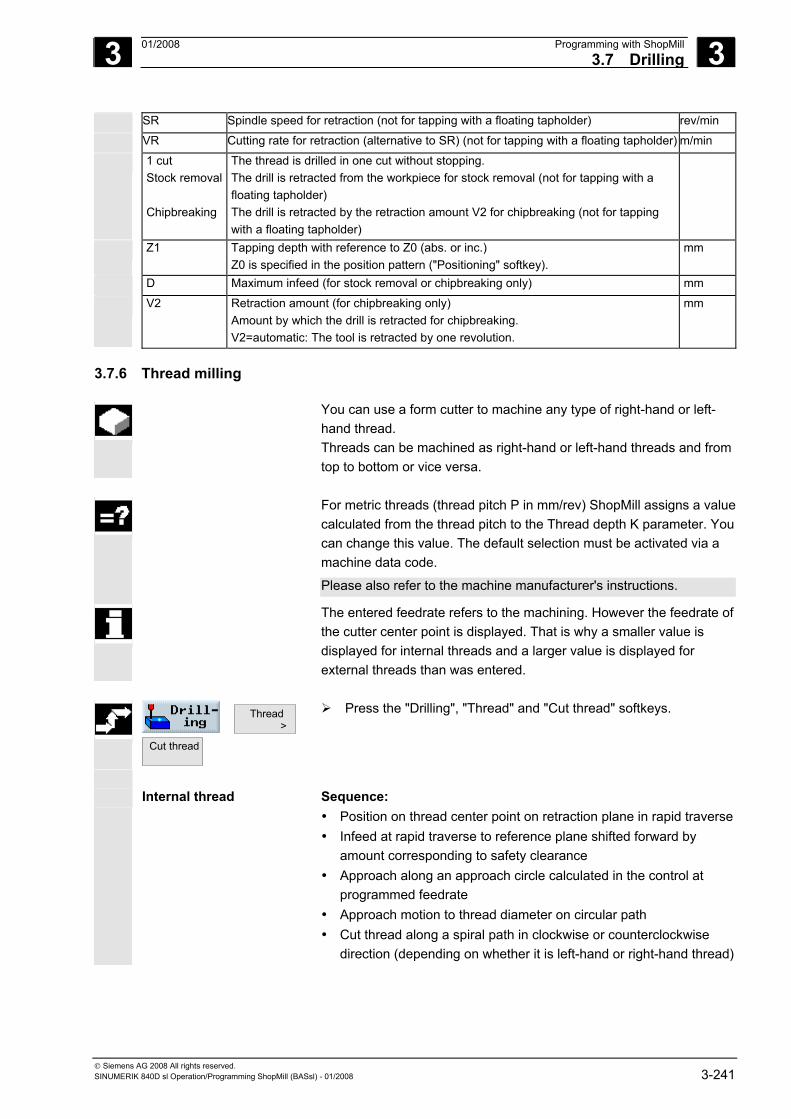
3 01/2008 Programming with ShopMill3.7 Drilling
3
© Siemens AG 2008 All rights reserved. SINUMERIK 840D sl Operation/Programming ShopMill (BASsl) - 01/2008 3-241
SR Spindle speed for retraction (not for tapping with a floating tapholder) rev/min
VR Cutting rate for retraction (alternative to SR) (not for tapping with a floating tapholder) m/min
1 cut Stock removal Chipbreaking
The thread is drilled in one cut without stopping. The drill is retracted from the workpiece for stock removal (not for tapping with a floating tapholder) The drill is retracted by the retraction amount V2 for chipbreaking (not for tapping with a floating tapholder)
Z1 Tapping depth with reference to Z0 (abs. or inc.) Z0 is specified in the position pattern ("Positioning" softkey).
mm
D Maximum infeed (for stock removal or chipbreaking only) mm
V2 Retraction amount (for chipbreaking only) Amount by which the drill is retracted for chipbreaking. V2=automatic: The tool is retracted by one revolution.
mm
3.7.6 Thread milling
You can use a form cutter to machine any type of right-hand or left-hand thread. Threads can be machined as right-hand or left-hand threads and from top to bottom or vice versa.
For metric threads (thread pitch P in mm/rev) ShopMill assigns a value
calculated from the thread pitch to the Thread depth K parameter. You can change this value. The default selection must be activated via a machine data code.
Please also refer to the machine manufacturer's instructions.
The entered feedrate refers to the machining. However the feedrate of the cutter center point is displayed. That is why a smaller value is displayed for internal threads and a larger value is displayed for external threads than was entered.
Thread >
Cut thread
Press the "Drilling", "Thread" and "Cut thread" softkeys.
Internal thread Sequence:
• Position on thread center point on retraction plane in rapid traverse• Infeed at rapid traverse to reference plane shifted forward by
amount corresponding to safety clearance • Approach along an approach circle calculated in the control at
programmed feedrate • Approach motion to thread diameter on circular path • Cut thread along a spiral path in clockwise or counterclockwise
direction (depending on whether it is left-hand or right-hand thread)
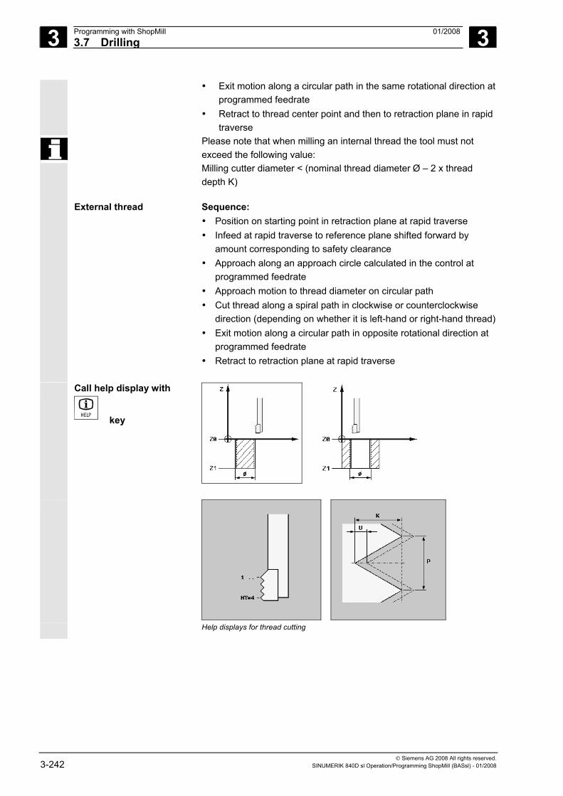
3 Programming with ShopMill 01/2008 3.7 Drilling
3
© Siemens AG 2008 All rights reserved. 3-242 SINUMERIK 840D sl Operation/Programming ShopMill (BASsl) - 01/2008
• Exit motion along a circular path in the same rotational direction at programmed feedrate
• Retract to thread center point and then to retraction plane in rapid traverse
Please note that when milling an internal thread the tool must not exceed the following value: Milling cutter diameter < (nominal thread diameter Ø – 2 x thread depth K)
External thread Sequence: • Position on starting point in retraction plane at rapid traverse • Infeed at rapid traverse to reference plane shifted forward by
amount corresponding to safety clearance • Approach along an approach circle calculated in the control at
programmed feedrate • Approach motion to thread diameter on circular path • Cut thread along a spiral path in clockwise or counterclockwise
direction (depending on whether it is left-hand or right-hand thread)• Exit motion along a circular path in opposite rotational direction at
programmed feedrate • Retract to retraction plane at rapid traverse
Call help display with
key
Help displays for thread cutting
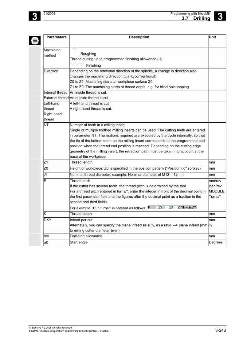
3 01/2008 Programming with ShopMill3.7 Drilling
3
© Siemens AG 2008 All rights reserved. SINUMERIK 840D sl Operation/Programming ShopMill (BASsl) - 01/2008 3-243
Parameters Description Unit
Machining method Roughing
Thread cutting up to programmed finishing allowance (U)
Finishing
Direction Depending on the rotational direction of the spindle, a change in direction also changes the machining direction (climb/conventional). Z0 to Z1: Machining starts at workpiece surface Z0. Z1 to Z0: The machining starts at thread depth, e.g. for blind hole tapping
Internal thread External thread
An inside thread is cut. An outside thread is cut.
Left-hand thread Right-hand thread
A left-hand thread is cut. A right-hand thread is cut.
NT Number of teeth in a milling insert. Single or multiple toothed milling inserts can be used. The cutting teeth are entered in parameter NT. The motions required are executed by the cycle internally, so that the tip of the bottom tooth on the milling insert corresponds to the programmed end position when the thread end position is reached. Depending on the cutting edge geometry of the milling insert, the retraction path must be taken into account at the base of the workpiece.
Z1 Thread length mm
Z0 Height of workpiece; Z0 is specified in the position pattern ("Positioning" softkey). mm
∅ Nominal thread diameter, example: Nominal diameter of M12 = 12mm mm
P Thread pitch If the cutter has several teeth, the thread pitch is determined by the tool. For a thread pitch entered in turns/'', enter the integer in front of the decimal point in the first parameter field and the figures after the decimal point as a fraction in the second and third fields.
For example, 13.5 turns/" is entered as follows:
mm/rev inch/rev MODULETurns/"
K Thread depth mm
DXY Infeed per cut Alternately, you can specify the plane infeed as a %, as a ratio --> plane infeed (mm) to milling cutter diameter (mm).
mm %
rev Finishing allowance mm
α0 Start angle Degrees
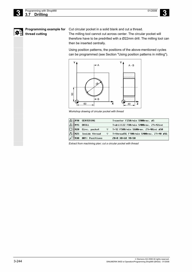
3 Programming with ShopMill 01/2008 3.7 Drilling
3
© Siemens AG 2008 All rights reserved. 3-244 SINUMERIK 840D sl Operation/Programming ShopMill (BASsl) - 01/2008
Programming example for thread cutting
Cut circular pocket in a solid blank and cut a thread. The milling tool cannot cut across center. The circular pocket will therefore have to be predrilled with a Ø22mm drill. The milling tool can then be inserted centrally.
Using position patterns, the positions of the above-mentioned cycles can be programmed (see Section "Using position patterns in milling").
X
Y
60 40 Z
YA A - B
B
50
56
Workshop drawing of circular pocket with thread
Extract from machining plan; cut a circular pocket with thread
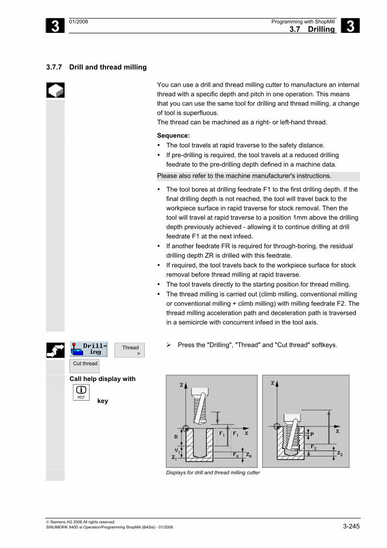
3 01/2008 Programming with ShopMill3.7 Drilling
3
© Siemens AG 2008 All rights reserved. SINUMERIK 840D sl Operation/Programming ShopMill (BASsl) - 01/2008 3-245
3.7.7 Drill and thread milling
You can use a drill and thread milling cutter to manufacture an internal thread with a specific depth and pitch in one operation. This means that you can use the same tool for drilling and thread milling, a change of tool is superfluous. The thread can be machined as a right- or left-hand thread.
Sequence: • The tool travels at rapid traverse to the safety distance. • If pre-drilling is required, the tool travels at a reduced drilling
feedrate to the pre-drilling depth defined in a machine data.
Please also refer to the machine manufacturer's instructions.
• The tool bores at drilling feedrate F1 to the first drilling depth. If the final drilling depth is not reached, the tool will travel back to the workpiece surface in rapid traverse for stock removal. Then the tool will travel at rapid traverse to a position 1mm above the drilling depth previously achieved - allowing it to continue drilling at drill feedrate F1 at the next infeed.
• If another feedrate FR is required for through-boring, the residual drilling depth ZR is drilled with this feedrate.
• If required, the tool travels back to the workpiece surface for stock removal before thread milling at rapid traverse.
• The tool travels directly to the starting position for thread milling. • The thread milling is carried out (climb milling, conventional milling
or conventional milling + climb milling) with milling feedrate F2. The thread milling acceleration path and deceleration path is traversed in a semicircle with concurrent infeed in the tool axis.
Thread >
Cut thread
Press the "Drilling", "Thread" and "Cut thread" softkeys.
Call help display with
key
Displays for drill and thread milling cutter
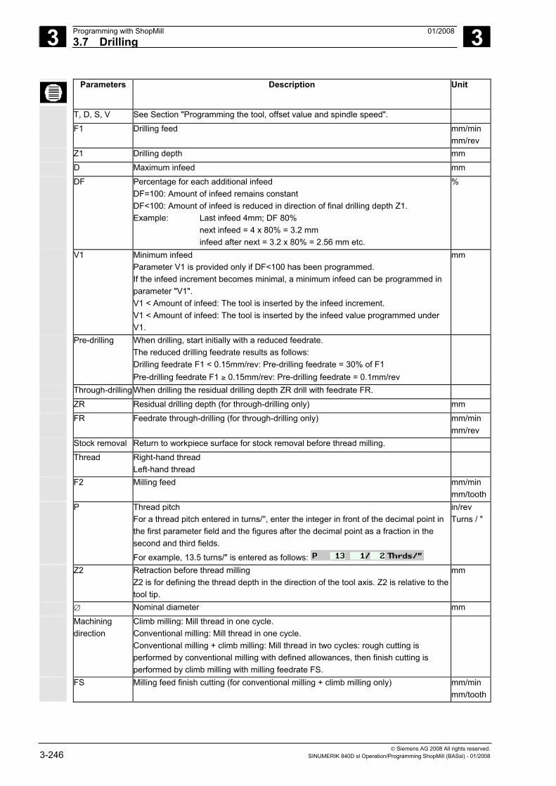
3 Programming with ShopMill 01/2008 3.7 Drilling
3
© Siemens AG 2008 All rights reserved. 3-246 SINUMERIK 840D sl Operation/Programming ShopMill (BASsl) - 01/2008
Parameters Description Unit
T, D, S, V See Section "Programming the tool, offset value and spindle speed".
F1 Drilling feed mm/min mm/rev
Z1 Drilling depth mm
D Maximum infeed mm
DF Percentage for each additional infeed DF=100: Amount of infeed remains constant DF<100: Amount of infeed is reduced in direction of final drilling depth Z1. Example: Last infeed 4mm; DF 80% next infeed = 4 x 80% = 3.2 mm infeed after next = 3.2 x 80% = 2.56 mm etc.
%
V1 Minimum infeed Parameter V1 is provided only if DF<100 has been programmed. If the infeed increment becomes minimal, a minimum infeed can be programmed in parameter "V1". V1 < Amount of infeed: The tool is inserted by the infeed increment. V1 < Amount of infeed: The tool is inserted by the infeed value programmed under V1.
mm
Pre-drilling When drilling, start initially with a reduced feedrate. The reduced drilling feedrate results as follows: Drilling feedrate F1 < 0.15mm/rev: Pre-drilling feedrate = 30% of F1 Pre-drilling feedrate F1 ≥ 0.15mm/rev: Pre-drilling feedrate = 0.1mm/rev
Through-drilling When drilling the residual drilling depth ZR drill with feedrate FR.
ZR Residual drilling depth (for through-drilling only) mm
FR Feedrate through-drilling (for through-drilling only) mm/min mm/rev
Stock removal Return to workpiece surface for stock removal before thread milling.
Thread Right-hand thread Left-hand thread
F2 Milling feed mm/min mm/tooth
P Thread pitch For a thread pitch entered in turns/'', enter the integer in front of the decimal point in the first parameter field and the figures after the decimal point as a fraction in the second and third fields.
For example, 13.5 turns/" is entered as follows:
in/rev Turns / "
Z2 Retraction before thread milling Z2 is for defining the thread depth in the direction of the tool axis. Z2 is relative to the tool tip.
mm
∅ Nominal diameter mm
Machining direction
Climb milling: Mill thread in one cycle. Conventional milling: Mill thread in one cycle. Conventional milling + climb milling: Mill thread in two cycles: rough cutting is performed by conventional milling with defined allowances, then finish cutting is performed by climb milling with milling feedrate FS.
FS Milling feed finish cutting (for conventional milling + climb milling only) mm/min mm/tooth
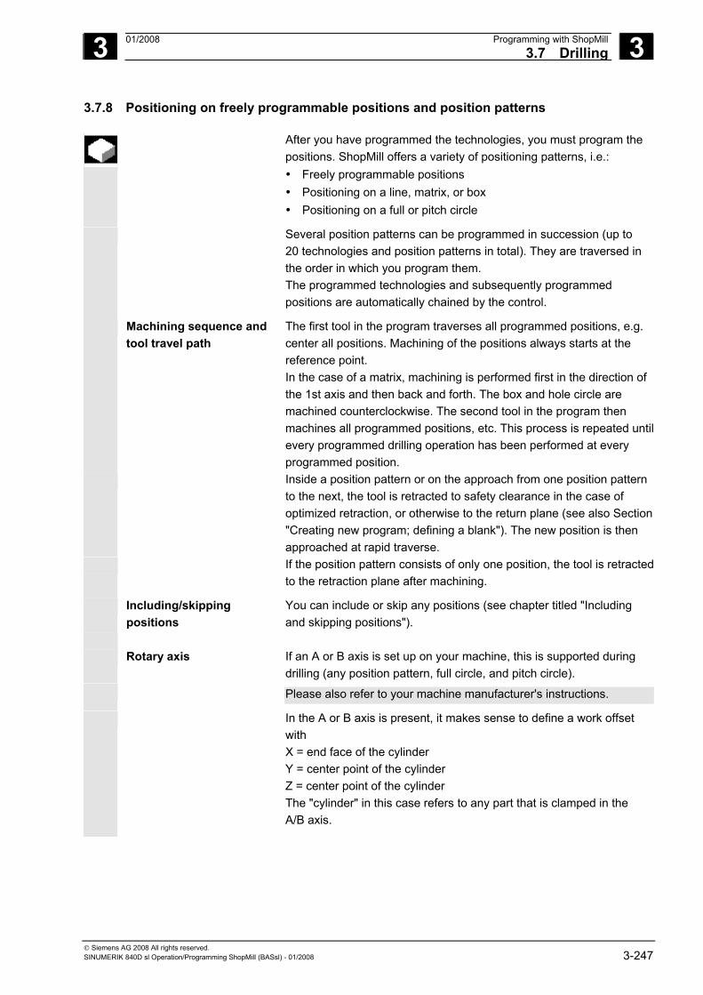
3 01/2008 Programming with ShopMill3.7 Drilling
3
© Siemens AG 2008 All rights reserved. SINUMERIK 840D sl Operation/Programming ShopMill (BASsl) - 01/2008 3-247
3.7.8 Positioning on freely programmable positions and position patterns
After you have programmed the technologies, you must program the positions. ShopMill offers a variety of positioning patterns, i.e.: • Freely programmable positions • Positioning on a line, matrix, or box • Positioning on a full or pitch circle
Several position patterns can be programmed in succession (up to 20 technologies and position patterns in total). They are traversed in the order in which you program them. The programmed technologies and subsequently programmed positions are automatically chained by the control.
Machining sequence and tool travel path
The first tool in the program traverses all programmed positions, e.g. center all positions. Machining of the positions always starts at the reference point. In the case of a matrix, machining is performed first in the direction of the 1st axis and then back and forth. The box and hole circle are machined counterclockwise. The second tool in the program then machines all programmed positions, etc. This process is repeated untilevery programmed drilling operation has been performed at every programmed position.
Inside a position pattern or on the approach from one position pattern to the next, the tool is retracted to safety clearance in the case of optimized retraction, or otherwise to the return plane (see also Section "Creating new program; defining a blank"). The new position is then approached at rapid traverse.
If the position pattern consists of only one position, the tool is retractedto the retraction plane after machining.
Including/skipping positions
You can include or skip any positions (see chapter titled "Including and skipping positions").
Rotary axis If an A or B axis is set up on your machine, this is supported during
drilling (any position pattern, full circle, and pitch circle). Please also refer to your machine manufacturer's instructions.
In the A or B axis is present, it makes sense to define a work offset with X = end face of the cylinder Y = center point of the cylinder Z = center point of the cylinder The "cylinder" in this case refers to any part that is clamped in the A/B axis.
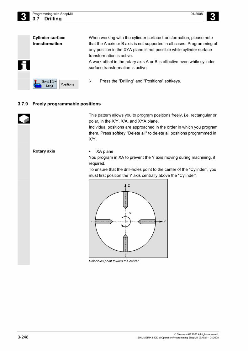
3 Programming with ShopMill 01/2008 3.7 Drilling
3
© Siemens AG 2008 All rights reserved. 3-248 SINUMERIK 840D sl Operation/Programming ShopMill (BASsl) - 01/2008
Cylinder surface transformation
When working with the cylinder surface transformation, please note that the A axis or B axis is not supported in all cases. Programming of any position in the XYA plane is not possible while cylinder surface transformation is active.
A work offset in the rotary axis A or B is effective even while cylinder surface transformation is active.
Positions
Press the "Drilling" and "Positions" softkeys.
3.7.9 Freely programmable positions
This pattern allows you to program positions freely, i.e. rectangular or polar, in the X/Y, X/A, and XYA plane. Individual positions are approached in the order in which you program them. Press softkey "Delete all" to delete all positions programmed in X/Y.
Rotary axis • XA plane
You program in XA to prevent the Y axis moving during machining, if required. To ensure that the drill-holes point to the center of the "Cylinder", you must first position the Y axis centrally above the "Cylinder".
A
Y
Z
A
Drill-holes point toward the center
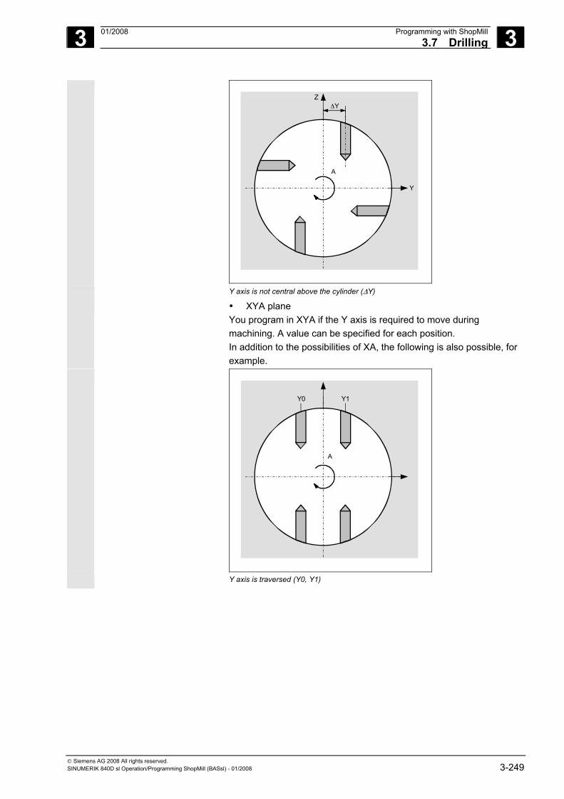
3 01/2008 Programming with ShopMill3.7 Drilling
3
© Siemens AG 2008 All rights reserved. SINUMERIK 840D sl Operation/Programming ShopMill (BASsl) - 01/2008 3-249
A
Y
ZΔY
A
Y axis is not central above the cylinder (ΔY) • XYA plane
You program in XYA if the Y axis is required to move during machining. A value can be specified for each position. In addition to the possibilities of XA, the following is also possible, for example.
A
Y
Z
A
Y0 Y1
A
Y axis is traversed (Y0, Y1)

3 Programming with ShopMill 01/2008 3.7 Drilling
3
© Siemens AG 2008 All rights reserved. 3-250 SINUMERIK 840D sl Operation/Programming ShopMill (BASsl) - 01/2008
Positions >
Press the "Drilling", "Positions" and "Freely Programmable Positions" softkeys.
Call help display with
key
Help display for "Freely programmable
positions, rectangular" Help display for "Freely programmable positions, polar"
Parameters Description XY
(without A/ or B axis support) Unit
Rectangular/ polar
Programming with rectangular or polar dimensions.
Z0 Height of workpiece (abs. or inc.) mm
X0 Y0
1st position of the hole in X (abs. or inc.) 1st position of the hole in Y (abs. or inc.)
mm mm
Rectangular: X1 - X8 Y1 – Y8
Other positions in the X axis (abs. or inc.) Other positions in the Y axis (abs. or inc.)
If you want to program further positions, store the ones you have already programmed and then open the parameter input form again by pressing softkey "Any positions".
mm mm
Polar: L1...L7 α1 ... α7
Position distance (abs.) Angle of rotation of line in relation to the X axis. Positive angle: Line is rotated counterclockwise. Negative angle: Line is rotated clockwise.
If you want to program further positions, store the ones you have already programmed and then open the parameter input form again by pressing softkey "Any positions".
mm Degrees
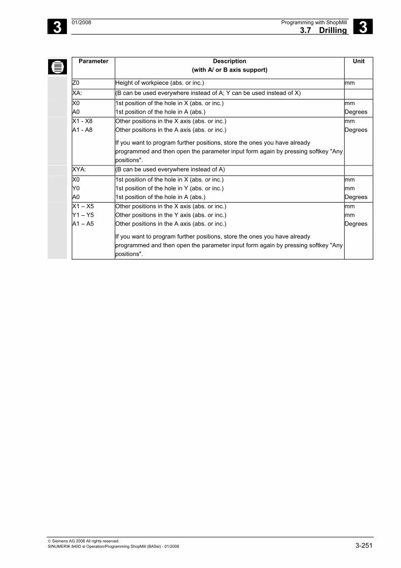
3 01/2008 Programming with ShopMill3.7 Drilling
3
© Siemens AG 2008 All rights reserved. SINUMERIK 840D sl Operation/Programming ShopMill (BASsl) - 01/2008 3-251
Parameter Description (with A/ or B axis support)
Unit
Z0 Height of workpiece (abs. or inc.) mm
XA: (B can be used everywhere instead of A; Y can be used instead of X)
X0 A0
1st position of the hole in X (abs. or inc.) 1st position of the hole in A (abs.)
mm Degrees
X1 - X8 A1 - A8
Other positions in the X axis (abs. or inc.) Other positions in the A axis (abs. or inc.)
If you want to program further positions, store the ones you have already programmed and then open the parameter input form again by pressing softkey "Any positions".
mm Degrees
XYA: (B can be used everywhere instead of A)
X0 Y0 A0
1st position of the hole in X (abs. or inc.) 1st position of the hole in Y (abs. or inc.) 1st position of the hole in A (abs.)
mm mm Degrees
X1 – X5 Y1 – Y5 A1 – A5
Other positions in the X axis (abs. or inc.) Other positions in the Y axis (abs. or inc.) Other positions in the A axis (abs. or inc.)
If you want to program further positions, store the ones you have already programmed and then open the parameter input form again by pressing softkey "Any positions".
mm mm Degrees
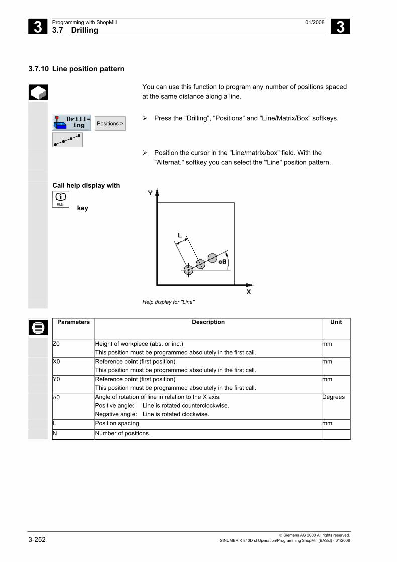
3 Programming with ShopMill 01/2008 3.7 Drilling
3
© Siemens AG 2008 All rights reserved. 3-252 SINUMERIK 840D sl Operation/Programming ShopMill (BASsl) - 01/2008
3.7.10 Line position pattern
You can use this function to program any number of positions spaced at the same distance along a line.
Positions >
Press the "Drilling", "Positions" and "Line/Matrix/Box" softkeys.
Position the cursor in the "Line/matrix/box" field. With the "Alternat." softkey you can select the "Line" position pattern.
Call help display with
key
Help display for "Line"
Parameters Description Unit
Z0 Height of workpiece (abs. or inc.) This position must be programmed absolutely in the first call.
mm
X0 Reference point (first position) This position must be programmed absolutely in the first call.
mm
Y0 Reference point (first position) This position must be programmed absolutely in the first call.
mm
α0 Angle of rotation of line in relation to the X axis. Positive angle: Line is rotated counterclockwise. Negative angle: Line is rotated clockwise.
Degrees
L Position spacing. mm
N Number of positions.
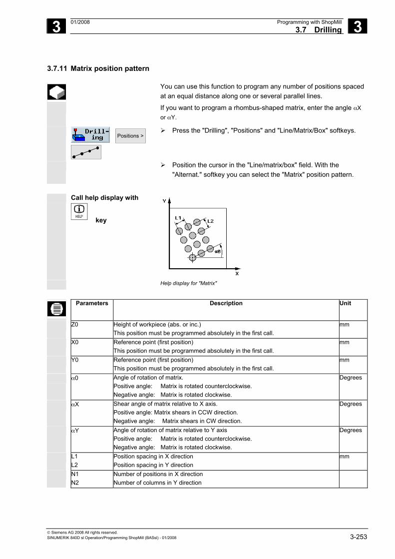
3 01/2008 Programming with ShopMill3.7 Drilling
3
© Siemens AG 2008 All rights reserved. SINUMERIK 840D sl Operation/Programming ShopMill (BASsl) - 01/2008 3-253
3.7.11 Matrix position pattern
You can use this function to program any number of positions spaced at an equal distance along one or several parallel lines.
If you want to program a rhombus-shaped matrix, enter the angle αX or αY.
Positions >
Press the "Drilling", "Positions" and "Line/Matrix/Box" softkeys.
Position the cursor in the "Line/matrix/box" field. With the "Alternat." softkey you can select the "Matrix" position pattern.
Call help display with
key
Help display for "Matrix"
Parameters Description Unit
Z0 Height of workpiece (abs. or inc.) This position must be programmed absolutely in the first call.
mm
X0 Reference point (first position) This position must be programmed absolutely in the first call.
mm
Y0 Reference point (first position) This position must be programmed absolutely in the first call.
mm
α0 Angle of rotation of matrix. Positive angle: Matrix is rotated counterclockwise. Negative angle: Matrix is rotated clockwise.
Degrees
αX Shear angle of matrix relative to X axis. Positive angle: Matrix shears in CCW direction. Negative angle: Matrix shears in CW direction.
Degrees
αY Angle of rotation of matrix relative to Y axis Positive angle: Matrix is rotated counterclockwise. Negative angle: Matrix is rotated clockwise.
Degrees
L1 L2
Position spacing in X direction Position spacing in Y direction
mm
N1 N2
Number of positions in X direction Number of columns in Y direction
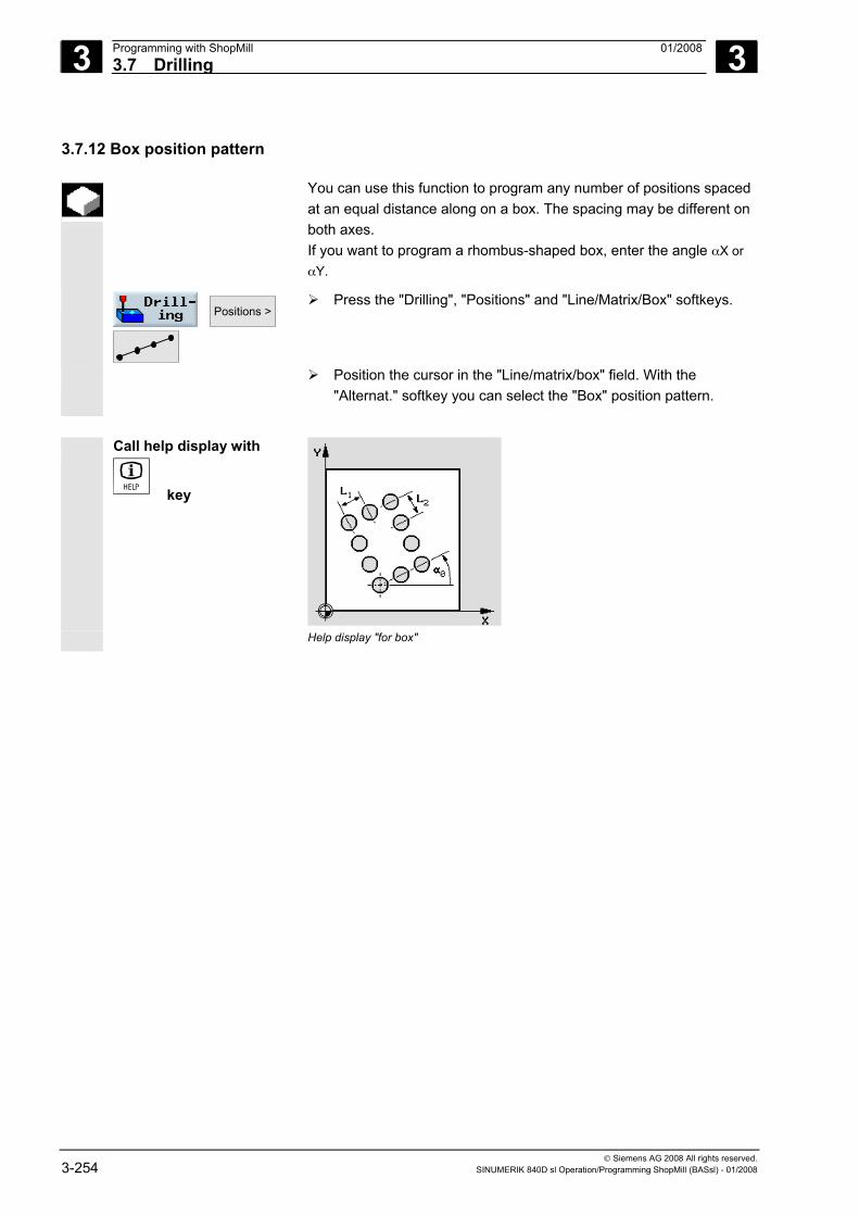
3 Programming with ShopMill 01/2008 3.7 Drilling
3
© Siemens AG 2008 All rights reserved. 3-254 SINUMERIK 840D sl Operation/Programming ShopMill (BASsl) - 01/2008
3.7.12 Box position pattern
You can use this function to program any number of positions spaced at an equal distance along on a box. The spacing may be different on both axes. If you want to program a rhombus-shaped box, enter the angle αX or αY.
Positions >
Press the "Drilling", "Positions" and "Line/Matrix/Box" softkeys.
Position the cursor in the "Line/matrix/box" field. With the "Alternat." softkey you can select the "Box" position pattern.
Call help display with
key
Help display "for box"
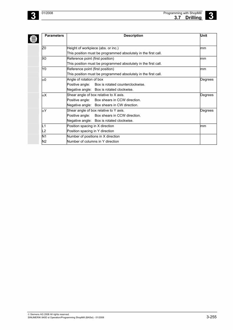
3 01/2008 Programming with ShopMill3.7 Drilling
3
© Siemens AG 2008 All rights reserved. SINUMERIK 840D sl Operation/Programming ShopMill (BASsl) - 01/2008 3-255
Parameters Description Unit
Z0 Height of workpiece (abs. or inc.) This position must be programmed absolutely in the first call.
mm
X0 Reference point (first position) This position must be programmed absolutely in the first call.
mm
Y0 Reference point (first position) This position must be programmed absolutely in the first call.
mm
α0 Angle of rotation of box Positive angle: Box is rotated counterclockwise. Negative angle: Box is rotated clockwise.
Degrees
αX Shear angle of box relative to X axis. Positive angle: Box shears in CCW direction. Negative angle: Box shears in CW direction.
Degrees
αY Shear angle of box relative to Y axis. Positive angle: Box shears in CCW direction. Negative angle: Box is rotated clockwise.
Degrees
L1 L2
Position spacing in X direction Position spacing in Y direction
mm
N1 N2
Number of positions in X direction Number of columns in Y direction
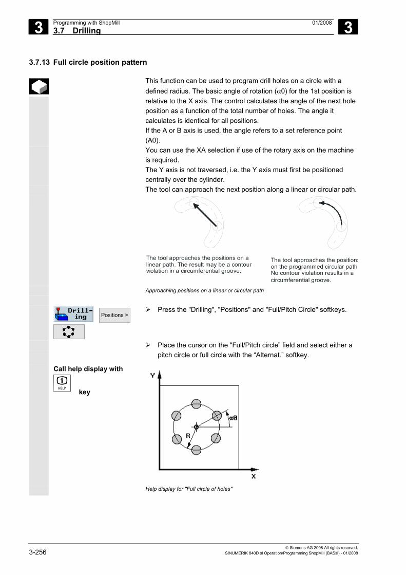
3 Programming with ShopMill 01/2008 3.7 Drilling
3
© Siemens AG 2008 All rights reserved. 3-256 SINUMERIK 840D sl Operation/Programming ShopMill (BASsl) - 01/2008
3.7.13 Full circle position pattern
This function can be used to program drill holes on a circle with a defined radius. The basic angle of rotation (α0) for the 1st position is relative to the X axis. The control calculates the angle of the next hole position as a function of the total number of holes. The angle it calculates is identical for all positions. If the A or B axis is used, the angle refers to a set reference point (A0).
You can use the XA selection if use of the rotary axis on the machine is required. The Y axis is not traversed, i.e. the Y axis must first be positioned centrally over the cylinder.
The tool can approach the next position along a linear or circular path.
The tool approaches the positions on a linear path. The result may be a contour violation in a circumferential groove.
The tool approaches the positionson the programmed circular path.No contour violation results in a circumferential groove.
Approaching positions on a linear or circular path
Positions >
Press the "Drilling", "Positions" and "Full/Pitch Circle" softkeys.
Place the cursor on the "Full/Pitch circle” field and select either a pitch circle or full circle with the “Alternat.” softkey.
Call help display with
key
Help display for "Full circle of holes"
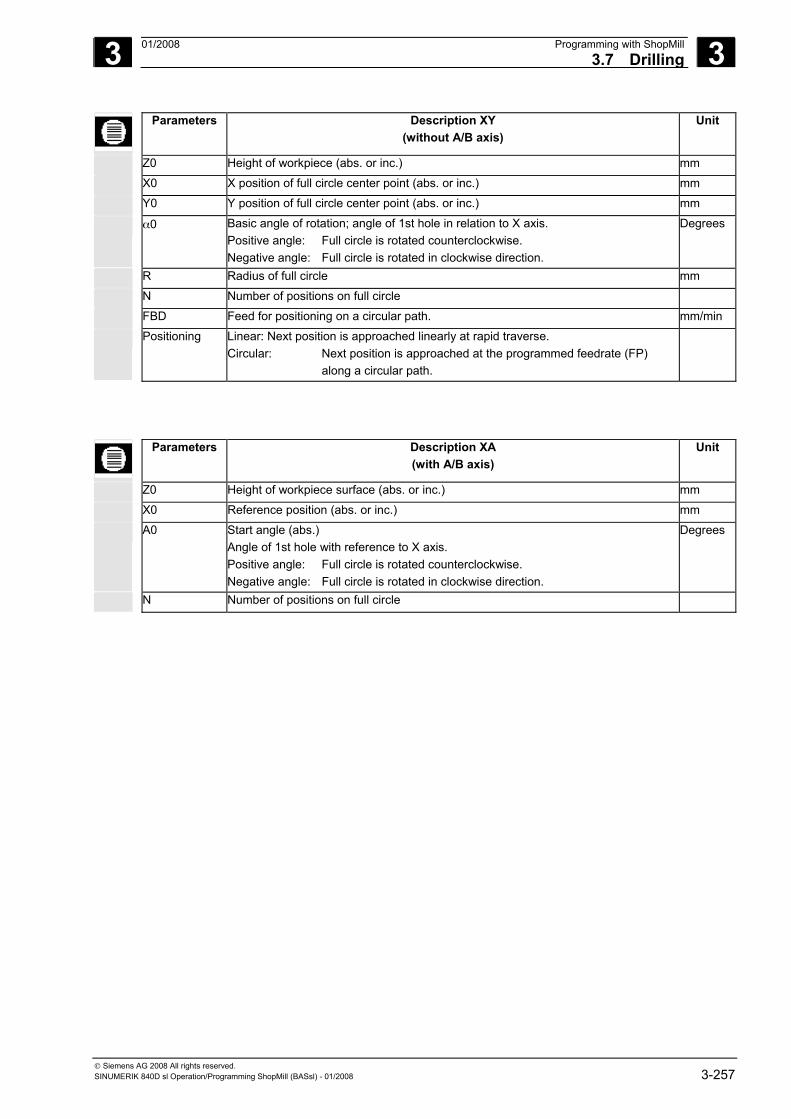
3 01/2008 Programming with ShopMill3.7 Drilling
3
© Siemens AG 2008 All rights reserved. SINUMERIK 840D sl Operation/Programming ShopMill (BASsl) - 01/2008 3-257
Parameters Description XY (without A/B axis)
Unit
Z0 Height of workpiece (abs. or inc.) mm
X0 X position of full circle center point (abs. or inc.) mm
Y0 Y position of full circle center point (abs. or inc.) mm
α0 Basic angle of rotation; angle of 1st hole in relation to X axis. Positive angle: Full circle is rotated counterclockwise. Negative angle: Full circle is rotated in clockwise direction.
Degrees
R Radius of full circle mm
N Number of positions on full circle
FBD Feed for positioning on a circular path. mm/min
Positioning Linear: Next position is approached linearly at rapid traverse. Circular: Next position is approached at the programmed feedrate (FP) along a circular path.
Parameters Description XA (with A/B axis)
Unit
Z0 Height of workpiece surface (abs. or inc.) mm
X0 Reference position (abs. or inc.) mm
A0 Start angle (abs.) Angle of 1st hole with reference to X axis. Positive angle: Full circle is rotated counterclockwise. Negative angle: Full circle is rotated in clockwise direction.
Degrees
N Number of positions on full circle
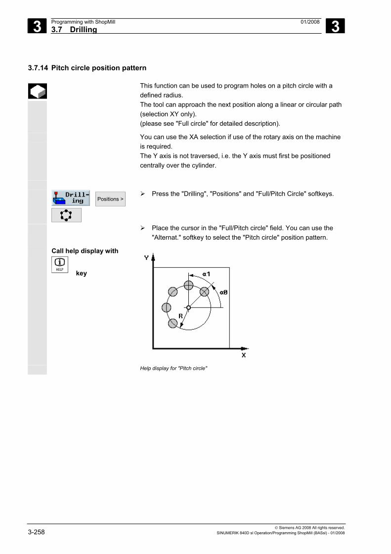
3 Programming with ShopMill 01/2008 3.7 Drilling
3
© Siemens AG 2008 All rights reserved. 3-258 SINUMERIK 840D sl Operation/Programming ShopMill (BASsl) - 01/2008
3.7.14 Pitch circle position pattern
This function can be used to program holes on a pitch circle with a defined radius. The tool can approach the next position along a linear or circular path (selection XY only). (please see "Full circle" for detailed description).
You can use the XA selection if use of the rotary axis on the machine is required. The Y axis is not traversed, i.e. the Y axis must first be positioned centrally over the cylinder.
Positions >
Press the "Drilling", "Positions" and "Full/Pitch Circle" softkeys.
Place the cursor in the "Full/Pitch circle" field. You can use the "Alternat." softkey to select the "Pitch circle" position pattern.
Call help display with
key
Help display for "Pitch circle"
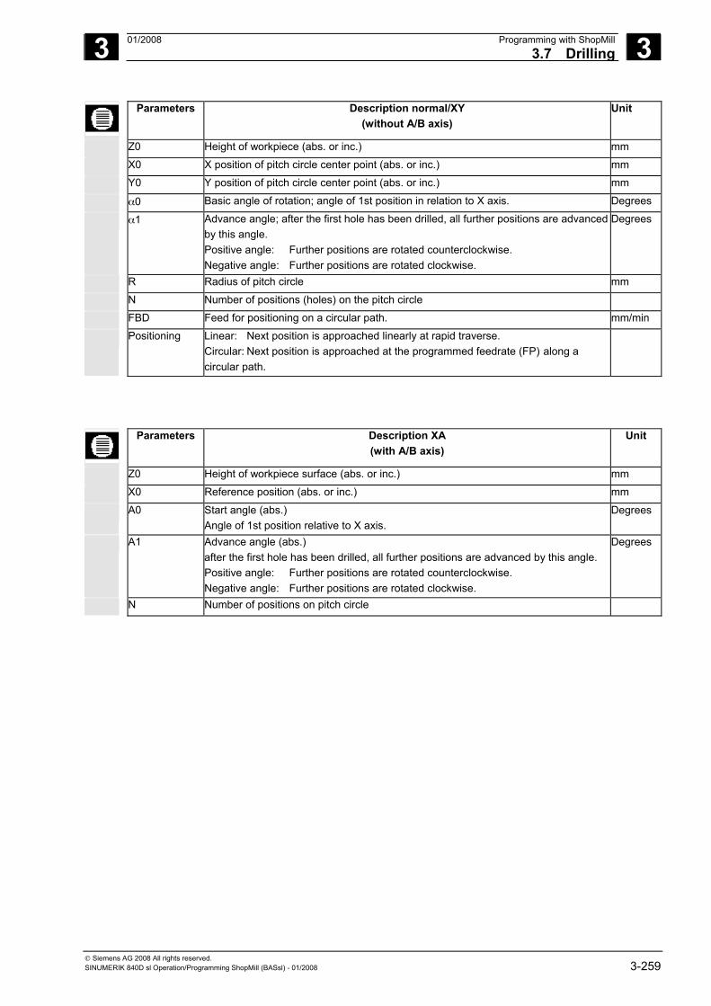
3 01/2008 Programming with ShopMill3.7 Drilling
3
© Siemens AG 2008 All rights reserved. SINUMERIK 840D sl Operation/Programming ShopMill (BASsl) - 01/2008 3-259
Parameters Description normal/XY (without A/B axis)
Unit
Z0 Height of workpiece (abs. or inc.) mm
X0 X position of pitch circle center point (abs. or inc.) mm
Y0 Y position of pitch circle center point (abs. or inc.) mm
α0 Basic angle of rotation; angle of 1st position in relation to X axis. Degrees α1 Advance angle; after the first hole has been drilled, all further positions are advanced
by this angle. Positive angle: Further positions are rotated counterclockwise. Negative angle: Further positions are rotated clockwise.
Degrees
R Radius of pitch circle mm
N Number of positions (holes) on the pitch circle
FBD Feed for positioning on a circular path. mm/min
Positioning Linear: Next position is approached linearly at rapid traverse. Circular: Next position is approached at the programmed feedrate (FP) along a circular path.
Parameters Description XA (with A/B axis)
Unit
Z0 Height of workpiece surface (abs. or inc.) mm
X0 Reference position (abs. or inc.) mm
A0 Start angle (abs.) Angle of 1st position relative to X axis.
Degrees
A1 Advance angle (abs.) after the first hole has been drilled, all further positions are advanced by this angle. Positive angle: Further positions are rotated counterclockwise. Negative angle: Further positions are rotated clockwise.
Degrees
N Number of positions on pitch circle
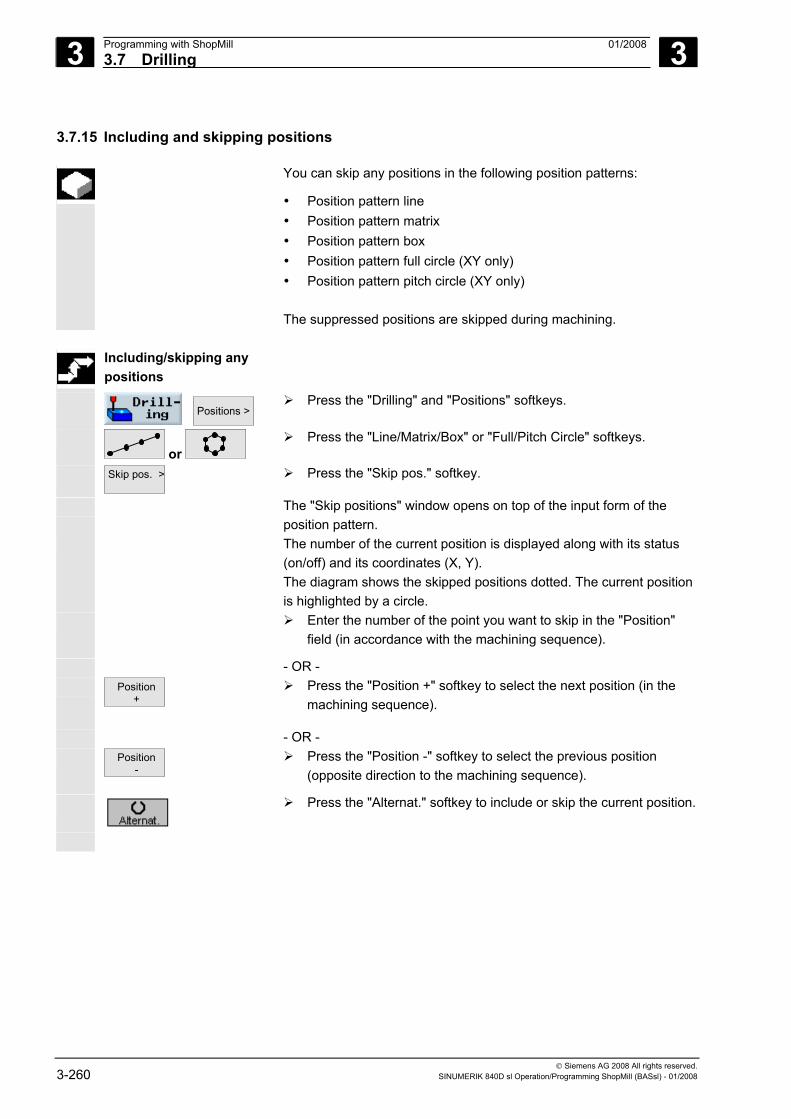
3 Programming with ShopMill 01/2008 3.7 Drilling
3
© Siemens AG 2008 All rights reserved. 3-260 SINUMERIK 840D sl Operation/Programming ShopMill (BASsl) - 01/2008
3.7.15 Including and skipping positions
You can skip any positions in the following position patterns:
• Position pattern line • Position pattern matrix • Position pattern box • Position pattern full circle (XY only) • Position pattern pitch circle (XY only) The suppressed positions are skipped during machining.
Including/skipping any
positions
Positions >
Press the "Drilling" and "Positions" softkeys.
or
Press the "Line/Matrix/Box" or "Full/Pitch Circle" softkeys.
Skip pos. >
Press the "Skip pos." softkey.
The "Skip positions" window opens on top of the input form of the position pattern.
The number of the current position is displayed along with its status (on/off) and its coordinates (X, Y). The diagram shows the skipped positions dotted. The current position is highlighted by a circle.
Enter the number of the point you want to skip in the "Position" field (in accordance with the machining sequence).
- OR - Position
+
Press the "Position +" softkey to select the next position (in the machining sequence).
- OR - Position
- Press the "Position -" softkey to select the previous position
(opposite direction to the machining sequence).
Press the "Alternat." softkey to include or skip the current position.
3 01/2008 Programming with ShopMill3.7 Drilling
3
© Siemens AG 2008 All rights reserved. SINUMERIK 840D sl Operation/Programming ShopMill (BASsl) - 01/2008 3-261
Including or skipping all positions at once
Skip all
Press the "Skip all" softkey to skip all positions.
Include all
Press the "Include all" softkey to include all positions again.
3.7.16 Obstacle
Function
If there is an obstacle between 2 position patterns, it can be crossed. The height of the obstacle can be programmed absolutely or incrementally.
If all positions in the 1st pattern have been machined, the tool axis travels in rapid traverse to a height corresponding to the obstacle height + safety clearance. The new position is approached in rapid traverse at this height. The tool axis then approaches a position corresponding to Z0 of the position pattern + safety clearance.
Positions >
Obstacle
Press the "Drilling", "Positions", and “Obstacle” softkeys.
Note Obstacles are registered only if they lie between 2 position patterns. If the tool change point and the programmed retraction plane are positioned below the obstacle, the tool travels to the retraction plane height and on to the new position without taking the obstacle into account. The obstacle must not be higher than the retraction plane.
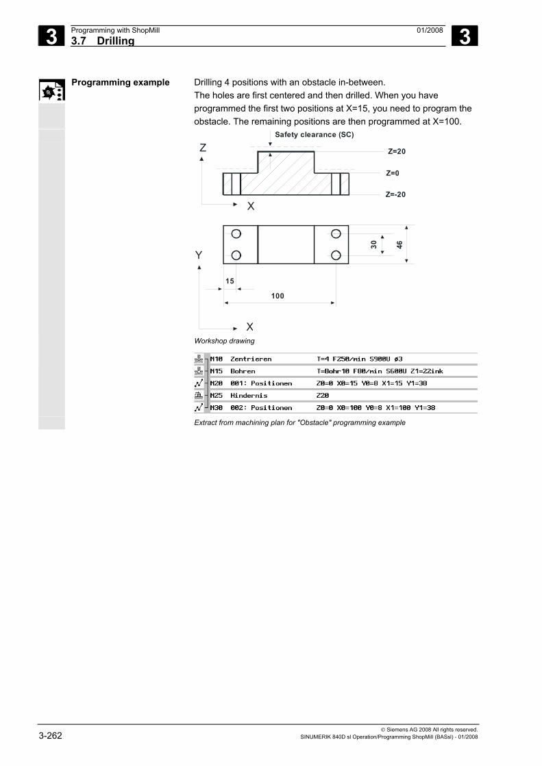
3 Programming with ShopMill 01/2008 3.7 Drilling
3
© Siemens AG 2008 All rights reserved. 3-262 SINUMERIK 840D sl Operation/Programming ShopMill (BASsl) - 01/2008
Programming example Drilling 4 positions with an obstacle in-between. The holes are first centered and then drilled. When you have programmed the first two positions at X=15, you need to program the obstacle. The remaining positions are then programmed at X=100.
Z=-20
Z=20
30
15
100
46
X
Y
X
Z
Z=0
Safety clearance (SC)
Workshop drawing
Extract from machining plan for "Obstacle" programming example
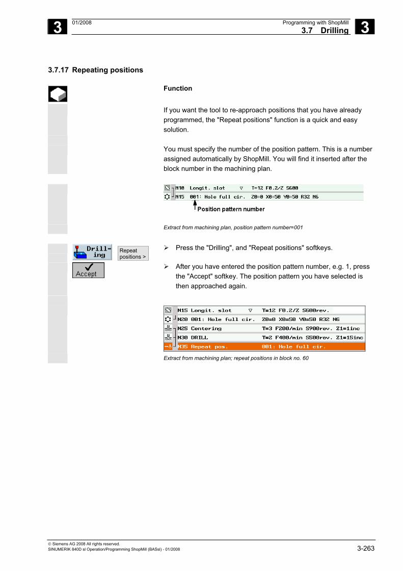
3 01/2008 Programming with ShopMill3.7 Drilling
3
© Siemens AG 2008 All rights reserved. SINUMERIK 840D sl Operation/Programming ShopMill (BASsl) - 01/2008 3-263
3.7.17 Repeating positions
Function
If you want the tool to re-approach positions that you have already programmed, the "Repeat positions" function is a quick and easy solution.
You must specify the number of the position pattern. This is a number
assigned automatically by ShopMill. You will find it inserted after the block number in the machining plan.
Extract from machining plan, position pattern number=001
Repeat positions >
Press the "Drilling", and "Repeat positions" softkeys.
After you have entered the position pattern number, e.g. 1, press the "Accept" softkey. The position pattern you have selected is then approached again.
Extract from machining plan; repeat positions in block no. 60
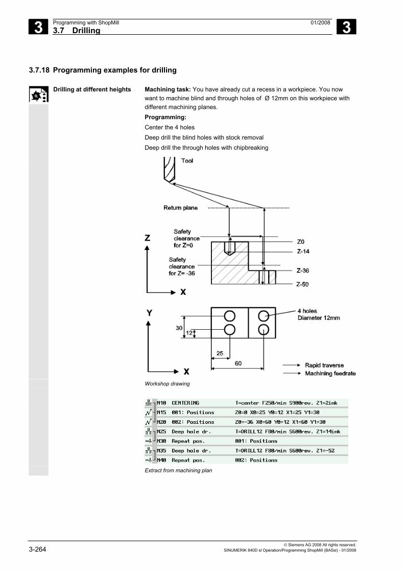
3 Programming with ShopMill 01/2008 3.7 Drilling
3
© Siemens AG 2008 All rights reserved. 3-264 SINUMERIK 840D sl Operation/Programming ShopMill (BASsl) - 01/2008
3.7.18 Programming examples for drilling
Drilling at different heights Machining task: You have already cut a recess in a workpiece. You now want to machine blind and through holes of Ø 12mm on this workpiece with different machining planes. Programming: Center the 4 holes Deep drill the blind holes with stock removal Deep drill the through holes with chipbreaking
Workshop drawing
Extract from machining plan
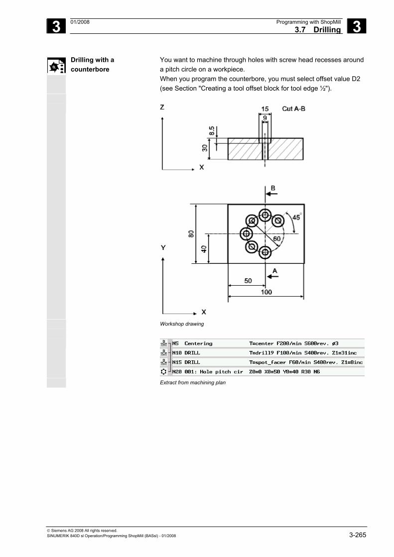
3 01/2008 Programming with ShopMill3.7 Drilling
3
© Siemens AG 2008 All rights reserved. SINUMERIK 840D sl Operation/Programming ShopMill (BASsl) - 01/2008 3-265
Drilling with a counterbore
You want to machine through holes with screw head recesses around a pitch circle on a workpiece. When you program the counterbore, you must select offset value D2 (see Section "Creating a tool offset block for tool edge ½").
Workshop drawing
Extract from machining plan

3 Programming with ShopMill 01/2008 3.8 Milling
3
© Siemens AG 2008 All rights reserved. 3-266 SINUMERIK 840D sl Operation/Programming ShopMill (BASsl) - 01/2008
3.8 Milling
3.8.1 Face milling
You can use this cycle to face mill any workpiece. A rectangular surface is always machined. The rectangle results from corner points 1 and 2 that are pre-assigned with the values of the blank part dimensions from the program header. Workpieces with and without limits can be face-milled.
To machine a work piece with four limits select the pocket cycles.
The cycle makes a distinction between roughing and finishing: Roughing: • Several material removal operations on surface • Tool turns above the workpiece edge
Finishing: • First material removal operation on surface • Tool turns at safety distance in the X/Y plane • Retraction of mill
Depth infeed always takes place outside the workpiece.
For a workpiece with edge breaking, select the rectangular spigot cycle.
In face milling, the effective tool diameter for a tool of type "Milling cutter" is stored in machine data.
Please also refer to the machine manufacturer's instructions.
Starting point For vertical machining, the starting point is always at the top or bottom. For horizontal machining, it is at the left or right. Machining is performed from outside to inside, if possible. The starting point is marked in the help display.
Facemilling
Press the "Milling" and "Face milling" softkeys.
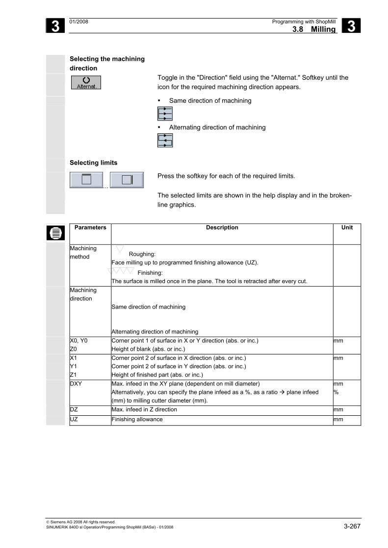
3 01/2008 Programming with ShopMill3.8 Milling
3
© Siemens AG 2008 All rights reserved. SINUMERIK 840D sl Operation/Programming ShopMill (BASsl) - 01/2008 3-267
Selecting the machining direction
Toggle in the "Direction" field using the "Alternat." Softkey until the icon for the required machining direction appears.
• Same direction of machining
• Alternating direction of machining
Selecting limits
...
Press the softkey for each of the required limits.
The selected limits are shown in the help display and in the broken-line graphics.
Parameters Description Unit
Machining method
Roughing: Face milling up to programmed finishing allowance (UZ).
Finishing: The surface is milled once in the plane. The tool is retracted after every cut.
Machining direction
Same direction of machining
Alternating direction of machining
X0, Y0 Z0
Corner point 1 of surface in X or Y direction (abs. or inc.) Height of blank (abs. or inc.)
mm
X1 Y1 Z1
Corner point 2 of surface in X direction (abs. or inc.) Corner point 2 of surface in Y direction (abs. or inc.) Height of finished part (abs. or inc.)
mm
DXY Max. infeed in the XY plane (dependent on mill diameter) Alternatively, you can specify the plane infeed as a %, as a ratio plane infeed (mm) to milling cutter diameter (mm).
mm %
DZ Max. infeed in Z direction mm
UZ Finishing allowance mm
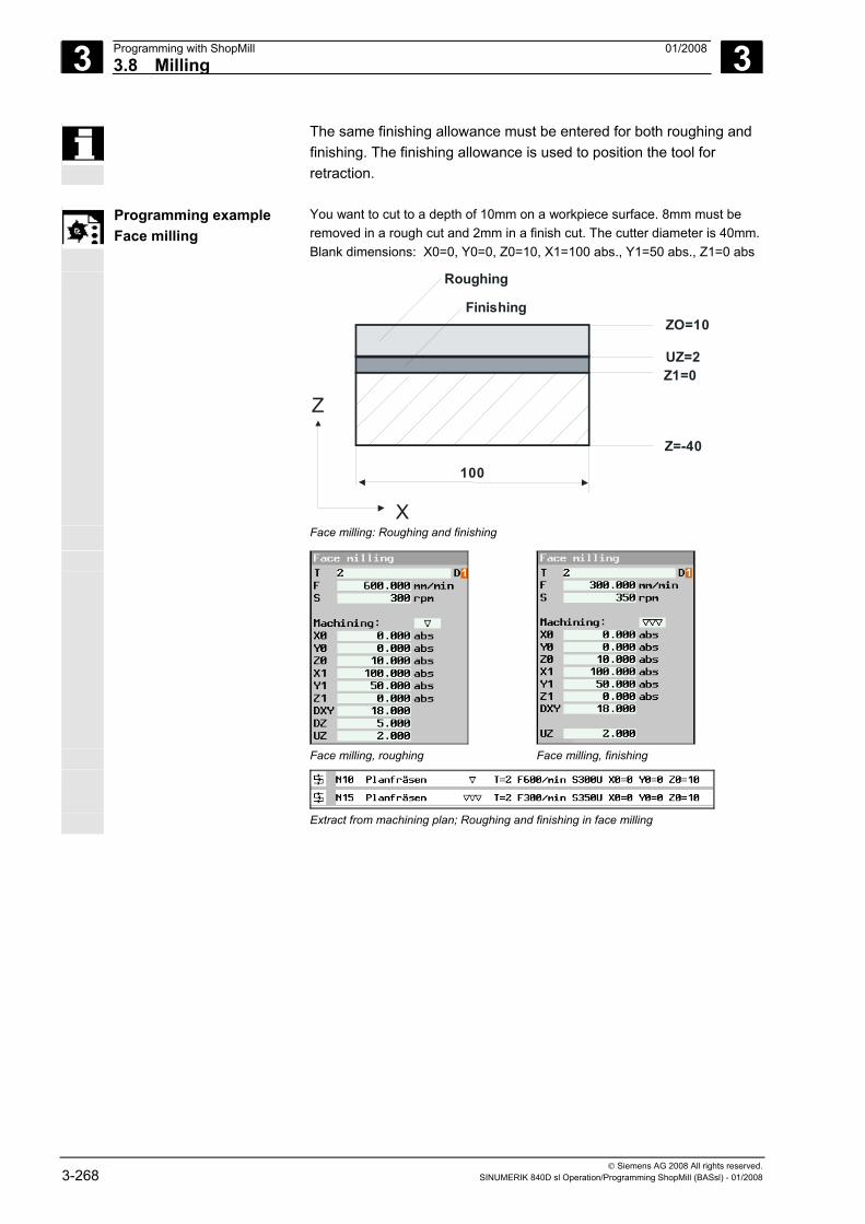
3 Programming with ShopMill 01/2008 3.8 Milling
3
© Siemens AG 2008 All rights reserved. 3-268 SINUMERIK 840D sl Operation/Programming ShopMill (BASsl) - 01/2008
The same finishing allowance must be entered for both roughing and finishing. The finishing allowance is used to position the tool for retraction.
Programming example
Face milling You want to cut to a depth of 10mm on a workpiece surface. 8mm must be removed in a rough cut and 2mm in a finish cut. The cutter diameter is 40mm.Blank dimensions: X0=0, Y0=0, Z0=10, X1=100 abs., Y1=50 abs., Z1=0 abs
UZ=2Z1=0
100
X
Z
ZO=10
Z=-40
Roughing
Finishing
Face milling: Roughing and finishing
Face milling, roughing Face milling, finishing
Extract from machining plan; Roughing and finishing in face milling
3 01/2008 Programming with ShopMill3.8 Milling
3
© Siemens AG 2008 All rights reserved. SINUMERIK 840D sl Operation/Programming ShopMill (BASsl) - 01/2008 3-269
3.8.2 Rectangular pocket
If you want to mill a rectangular pocket, use the "Rectangular pocket" function.
The following machining methods are available:
• Milling rectangular pocket from solid material • Pre-drilling a rectangular pocket in the center first if, for example,
the milling cutter does not cut across the center (program the drilling, rectangular pocket and position program blocks one after the other).
• Machining pre-machined rectangular pocket (see "Machining" parameter).
Depending on the dimensions of the rectangular pocket in the workpiece drawing, you can select a corresponding reference point for the rectangular pocket.
Approach/retraction 1. The tool approaches the center point of the pocket at rapid traverse at the height of the retraction plane and adjusts to the safety clearance.
2. The tool is inserted into the material according to the method selected.
3. The pocket is always machined from inside out using the selected machining method.
4. The tool moves back to the safety distance at rapid traverse.
Machining method You can select the machining mode for milling the rectangular pocket as follows: • Roughing
During roughing, the individual planes of the pocket are machined one after the other from center point until depth Z1 is reached.
• Finishing In "Finishing" mode, the edge is always machined first. The pocket edge is approached on the quadrant that joins the corner radius. During the last infeed, the base is finished from the center out.
• Edge finishing Edge finishing is performed in the same way as finishing, except that the last infeed (finish base) is omitted.
• Chamfer Chamfering involves edge breaking at the upper edge of the pocket.
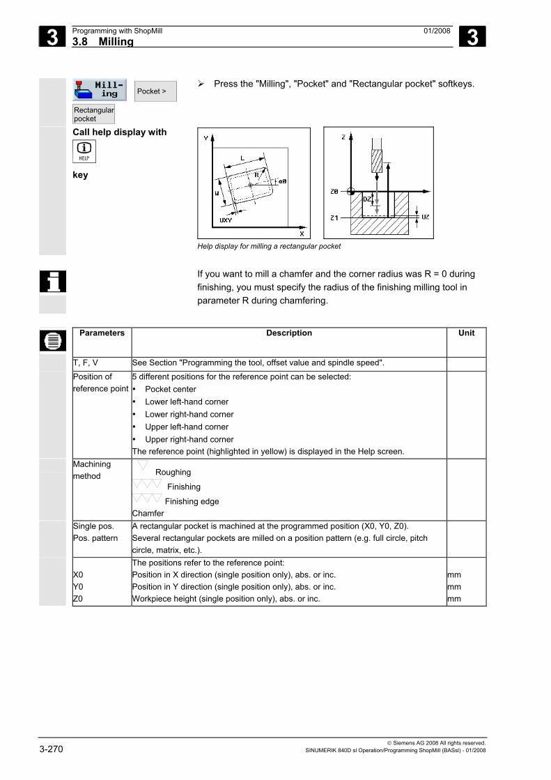
3 Programming with ShopMill 01/2008 3.8 Milling
3
© Siemens AG 2008 All rights reserved. 3-270 SINUMERIK 840D sl Operation/Programming ShopMill (BASsl) - 01/2008
Pocket >
Rectangularpocket
Press the "Milling", "Pocket" and "Rectangular pocket" softkeys.
Call help display with
key
Help display for milling a rectangular pocket
If you want to mill a chamfer and the corner radius was R = 0 during finishing, you must specify the radius of the finishing milling tool in parameter R during chamfering.
Parameters Description Unit
T, F, V See Section "Programming the tool, offset value and spindle speed".
Position of reference point
5 different positions for the reference point can be selected: • Pocket center • Lower left-hand corner • Lower right-hand corner • Upper left-hand corner • Upper right-hand corner The reference point (highlighted in yellow) is displayed in the Help screen.
Machining method Roughing
Finishing
Finishing edge Chamfer
Single pos. Pos. pattern
A rectangular pocket is machined at the programmed position (X0, Y0, Z0). Several rectangular pockets are milled on a position pattern (e.g. full circle, pitch circle, matrix, etc.).
X0 Y0 Z0
The positions refer to the reference point: Position in X direction (single position only), abs. or inc. Position in Y direction (single position only), abs. or inc. Workpiece height (single position only), abs. or inc.
mm mm mm
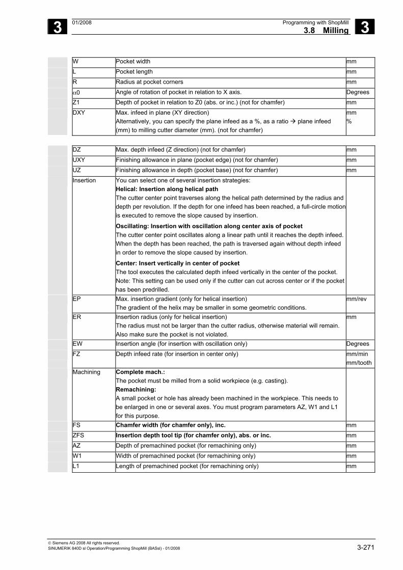
3 01/2008 Programming with ShopMill3.8 Milling
3
© Siemens AG 2008 All rights reserved. SINUMERIK 840D sl Operation/Programming ShopMill (BASsl) - 01/2008 3-271
W Pocket width mm
L Pocket length mm
R Radius at pocket corners mm
α0 Angle of rotation of pocket in relation to X axis. Degrees Z1 Depth of pocket in relation to Z0 (abs. or inc.) (not for chamfer) mm
DXY Max. infeed in plane (XY direction) Alternatively, you can specify the plane infeed as a %, as a ratio plane infeed (mm) to milling cutter diameter (mm). (not for chamfer)
mm %
DZ Max. depth infeed (Z direction) (not for chamfer) mm
UXY Finishing allowance in plane (pocket edge) (not for chamfer) mm
UZ Finishing allowance in depth (pocket base) (not for chamfer) mm
Insertion
You can select one of several insertion strategies: Helical: Insertion along helical path The cutter center point traverses along the helical path determined by the radius and depth per revolution. If the depth for one infeed has been reached, a full-circle motion is executed to remove the slope caused by insertion.
Oscillating: Insertion with oscillation along center axis of pocket The cutter center point oscillates along a linear path until it reaches the depth infeed. When the depth has been reached, the path is traversed again without depth infeed in order to remove the slope caused by insertion.
Center: Insert vertically in center of pocket The tool executes the calculated depth infeed vertically in the center of the pocket. Note: This setting can be used only if the cutter can cut across center or if the pocket has been predrilled.
EP Max. insertion gradient (only for helical insertion) The gradient of the helix may be smaller in some geometric conditions.
mm/rev
ER Insertion radius (only for helical insertion) The radius must not be larger than the cutter radius, otherwise material will remain. Also make sure the pocket is not violated.
mm
EW Insertion angle (for insertion with oscillation only) Degrees FZ Depth infeed rate (for insertion in center only) mm/min
mm/tooth Machining Complete mach.:
The pocket must be milled from a solid workpiece (e.g. casting). Remachining: A small pocket or hole has already been machined in the workpiece. This needs to be enlarged in one or several axes. You must program parameters AZ, W1 and L1 for this purpose.
FS Chamfer width (for chamfer only), inc. mm
ZFS Insertion depth tool tip (for chamfer only), abs. or inc. mm
AZ Depth of premachined pocket (for remachining only) mm
W1 Width of premachined pocket (for remachining only) mm
L1 Length of premachined pocket (for remachining only) mm
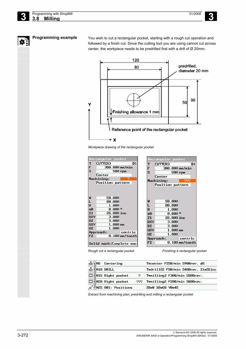
3 Programming with ShopMill 01/2008 3.8 Milling
3
© Siemens AG 2008 All rights reserved. 3-272 SINUMERIK 840D sl Operation/Programming ShopMill (BASsl) - 01/2008
Programming example You wish to cut a rectangular pocket, starting with a rough cut operation and followed by a finish cut. Since the cutting tool you are using cannot cut across center, the workpiece needs to be predrilled first with a drill of Ø 20mm.
Workpiece drawing of the rectangular pocket
Rough cut a rectangular pocket Finishing a rectangular pocket
Extract from machining plan; predrilling and milling a rectangular pocket
3 01/2008 Programming with ShopMill3.8 Milling
3
© Siemens AG 2008 All rights reserved. SINUMERIK 840D sl Operation/Programming ShopMill (BASsl) - 01/2008 3-273
3.8.3 Circular pocket
Use the "Circular pocket" function if you want to mill any kind of circular pocket.
The following machining methods are available:
• Milling a circular pocket from solid material • Pre-drilling a circular pocket in the center first if, for example, the
milling cutter does not cut across the center (program the drilling, circular pocket and position program blocks one after the other).
• Machine pre-machined circular pocket (see "Machining" parameter).
For milling with the "circular pocket" function two methods are available, the plane-by-plane method and the helical method.
Plane-by-plane machining
In plane-by-plane machining of the pocket, the material is removed horizontally, one layer at a time.
Approach/retraction 1. The tool approaches the center point of the pocket at rapid traverse at the height of the retraction plane and adjusts to the safety distance.
2. The tool is inserted into the material according to the method selected.
3. The pocket is always machined from inside out using the selected machining method.
4. The tool moves back to the safety distance at rapid traverse.
Machining method You can select the machining mode for milling the circular pocket as follows: • Roughing
During roughing, the individual planes of the pocket are machined one after the other from center point until depth Z1 is reached.
• Finishing In "Finishing" mode, the edge is always machined first. The pocket edge is approached on the quadrant that joins the pocket radius. During the last infeed, the base is finished from the center out.
• Edge finishing Edge finishing is performed in the same way as finishing, except that the last infeed (finish base) is omitted.
• Chamfer Chamfering involves edge breaking at the upper edge of the pocket.
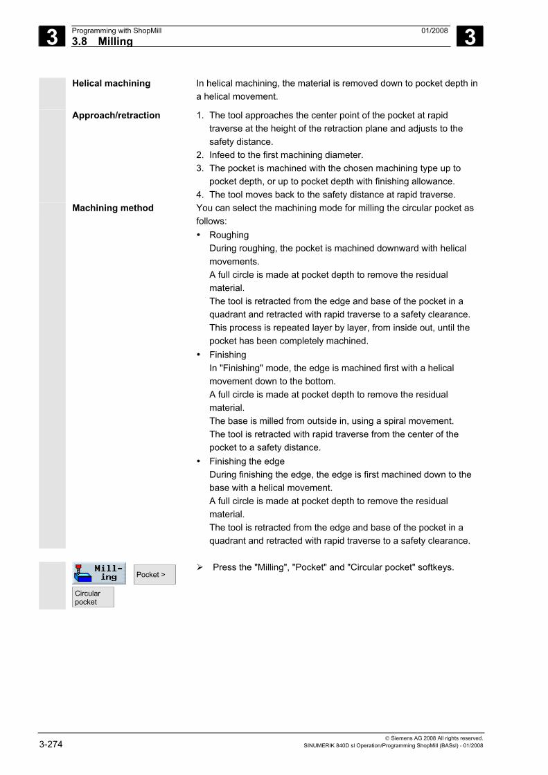
3 Programming with ShopMill 01/2008 3.8 Milling
3
© Siemens AG 2008 All rights reserved. 3-274 SINUMERIK 840D sl Operation/Programming ShopMill (BASsl) - 01/2008
Helical machining In helical machining, the material is removed down to pocket depth in a helical movement.
Approach/retraction 1. The tool approaches the center point of the pocket at rapid traverse at the height of the retraction plane and adjusts to the safety distance.
2. Infeed to the first machining diameter. 3. The pocket is machined with the chosen machining type up to
pocket depth, or up to pocket depth with finishing allowance. 4. The tool moves back to the safety distance at rapid traverse.
Machining method You can select the machining mode for milling the circular pocket as follows: • Roughing
During roughing, the pocket is machined downward with helical movements. A full circle is made at pocket depth to remove the residual material. The tool is retracted from the edge and base of the pocket in a quadrant and retracted with rapid traverse to a safety clearance. This process is repeated layer by layer, from inside out, until the pocket has been completely machined.
• Finishing In "Finishing" mode, the edge is machined first with a helical movement down to the bottom. A full circle is made at pocket depth to remove the residual material. The base is milled from outside in, using a spiral movement. The tool is retracted with rapid traverse from the center of the pocket to a safety distance.
• Finishing the edge During finishing the edge, the edge is first machined down to the base with a helical movement. A full circle is made at pocket depth to remove the residual material. The tool is retracted from the edge and base of the pocket in a quadrant and retracted with rapid traverse to a safety clearance.
Pocket >
Circularpocket
Press the "Milling", "Pocket" and "Circular pocket" softkeys.
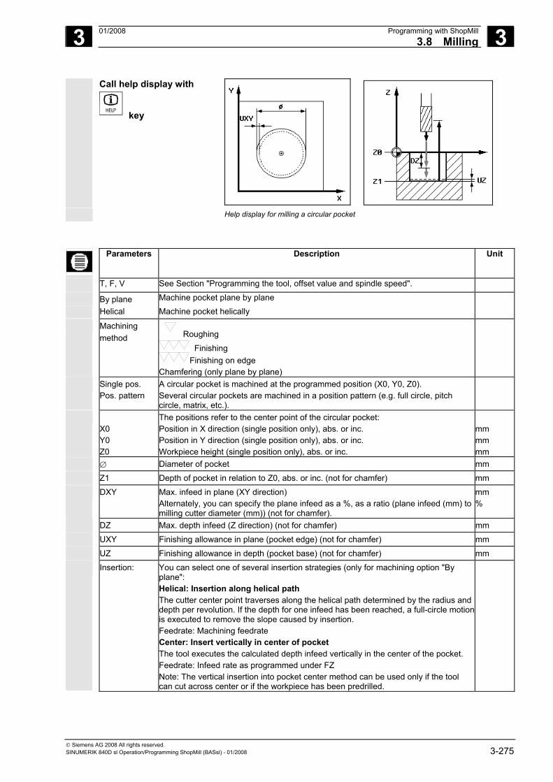
3 01/2008 Programming with ShopMill3.8 Milling
3
© Siemens AG 2008 All rights reserved. SINUMERIK 840D sl Operation/Programming ShopMill (BASsl) - 01/2008 3-275
Call help display with
key
Help display for milling a circular pocket
Parameters Description Unit
T, F, V See Section "Programming the tool, offset value and spindle speed".
By plane Helical
Machine pocket plane by plane Machine pocket helically
Machining method Roughing
Finishing Finishing on edge
Chamfering (only plane by plane)
Single pos. Pos. pattern
A circular pocket is machined at the programmed position (X0, Y0, Z0). Several circular pockets are machined in a position pattern (e.g. full circle, pitch circle, matrix, etc.).
X0 Y0 Z0
The positions refer to the center point of the circular pocket: Position in X direction (single position only), abs. or inc. Position in Y direction (single position only), abs. or inc. Workpiece height (single position only), abs. or inc.
mm mm mm
∅ Diameter of pocket mm Z1 Depth of pocket in relation to Z0, abs. or inc. (not for chamfer) mm DXY Max. infeed in plane (XY direction)
Alternately, you can specify the plane infeed as a %, as a ratio (plane infeed (mm) to milling cutter diameter (mm)) (not for chamfer).
mm %
DZ Max. depth infeed (Z direction) (not for chamfer) mm UXY Finishing allowance in plane (pocket edge) (not for chamfer) mm UZ Finishing allowance in depth (pocket base) (not for chamfer) mm Insertion:
You can select one of several insertion strategies (only for machining option "By plane": Helical: Insertion along helical path The cutter center point traverses along the helical path determined by the radius and depth per revolution. If the depth for one infeed has been reached, a full-circle motion is executed to remove the slope caused by insertion. Feedrate: Machining feedrate Center: Insert vertically in center of pocket The tool executes the calculated depth infeed vertically in the center of the pocket. Feedrate: Infeed rate as programmed under FZ Note: The vertical insertion into pocket center method can be used only if the tool can cut across center or if the workpiece has been predrilled.
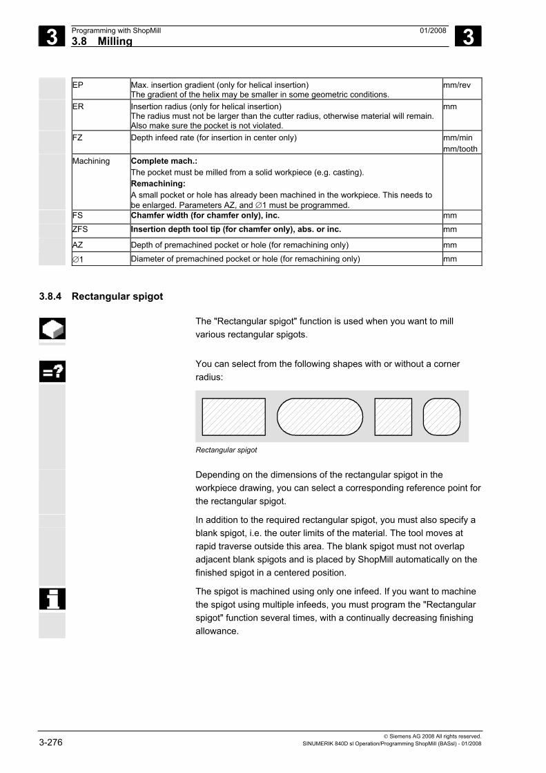
3 Programming with ShopMill 01/2008 3.8 Milling
3
© Siemens AG 2008 All rights reserved. 3-276 SINUMERIK 840D sl Operation/Programming ShopMill (BASsl) - 01/2008
EP Max. insertion gradient (only for helical insertion) The gradient of the helix may be smaller in some geometric conditions.
mm/rev
ER Insertion radius (only for helical insertion) The radius must not be larger than the cutter radius, otherwise material will remain. Also make sure the pocket is not violated.
mm
FZ Depth infeed rate (for insertion in center only) mm/min mm/tooth
Machining Complete mach.: The pocket must be milled from a solid workpiece (e.g. casting). Remachining: A small pocket or hole has already been machined in the workpiece. This needs to be enlarged. Parameters AZ, and ∅1 must be programmed.
FS Chamfer width (for chamfer only), inc. mm
ZFS Insertion depth tool tip (for chamfer only), abs. or inc. mm
AZ Depth of premachined pocket or hole (for remachining only) mm ∅1 Diameter of premachined pocket or hole (for remachining only) mm
3.8.4 Rectangular spigot
The "Rectangular spigot" function is used when you want to mill various rectangular spigots.
You can select from the following shapes with or without a corner
radius:
Rectangular spigot
Depending on the dimensions of the rectangular spigot in the
workpiece drawing, you can select a corresponding reference point for the rectangular spigot.
In addition to the required rectangular spigot, you must also specify a blank spigot, i.e. the outer limits of the material. The tool moves at rapid traverse outside this area. The blank spigot must not overlap adjacent blank spigots and is placed by ShopMill automatically on the finished spigot in a centered position.
The spigot is machined using only one infeed. If you want to machine the spigot using multiple infeeds, you must program the "Rectangular spigot" function several times, with a continually decreasing finishing allowance.
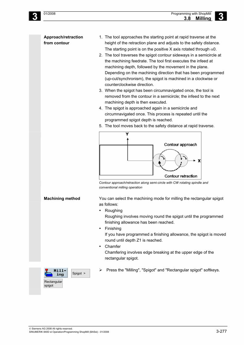
3 01/2008 Programming with ShopMill3.8 Milling
3
© Siemens AG 2008 All rights reserved. SINUMERIK 840D sl Operation/Programming ShopMill (BASsl) - 01/2008 3-277
Approach/retraction from contour
1. The tool approaches the starting point at rapid traverse at the height of the retraction plane and adjusts to the safety distance. The starting point is on the positive X axis rotated through α0.
2. The tool traverses the spigot contour sideways in a semicircle at the machining feedrate. The tool first executes the infeed at machining depth, followed by the movement in the plane. Depending on the machining direction that has been programmed (up-cut/synchronism), the spigot is machined in a clockwise or counterclockwise direction.
3. When the spigot has been circumnavigated once, the tool is removed from the contour in a semicircle; the infeed to the next machining depth is then executed.
4. The spigot is approached again in a semicircle and circumnavigated once. This process is repeated until the programmed spigot depth is reached.
5. The tool moves back to the safety distance at rapid traverse.
Contour approach/retraction along semi-circle with CW rotating spindle and
conventional milling operation
Machining method You can select the machining mode for milling the rectangular spigot
as follows: • Roughing
Roughing involves moving round the spigot until the programmed finishing allowance has been reached.
• Finishing If you have programmed a finishing allowance, the spigot is moved round until depth Z1 is reached.
• Chamfer Chamfering involves edge breaking at the upper edge of the rectangular spigot.
Spigot >
Rectangularspigot
Press the "Milling", "Spigot" and "Rectangular spigot" softkeys.
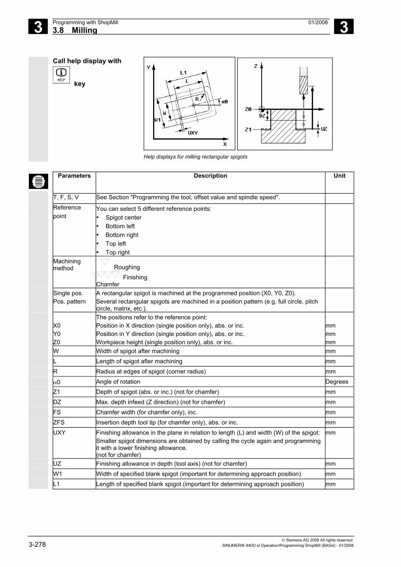
3 Programming with ShopMill 01/2008 3.8 Milling
3
© Siemens AG 2008 All rights reserved. 3-278 SINUMERIK 840D sl Operation/Programming ShopMill (BASsl) - 01/2008
Call help display with
key
Help displays for milling rectangular spigots
Parameters Description Unit
T, F, S, V See Section "Programming the tool, offset value and spindle speed".
Reference point
You can select 5 different reference points: • Spigot center • Bottom left • Bottom right • Top left • Top right
Machining method Roughing
Finishing Chamfer
Single pos. Pos. pattern
A rectangular spigot is machined at the programmed position (X0, Y0, Z0). Several rectangular spigots are machined in a position pattern (e.g. full circle, pitch circle, matrix, etc.).
X0 Y0 Z0
The positions refer to the reference point: Position in X direction (single position only), abs. or inc. Position in Y direction (single position only), abs. or inc. Workpiece height (single position only), abs. or inc.
mm mm mm
W Width of spigot after machining mm L Length of spigot after machining mm R Radius at edges of spigot (corner radius) mm α0 Angle of rotation Degrees Z1 Depth of spigot (abs. or inc.) (not for chamfer) mm DZ Max. depth infeed (Z direction) (not for chamfer) mm FS Chamfer width (for chamfer only), inc. mm ZFS Insertion depth tool tip (for chamfer only), abs. or inc. mm UXY Finishing allowance in the plane in relation to length (L) and width (W) of the spigot;
Smaller spigot dimensions are obtained by calling the cycle again and programming it with a lower finishing allowance. (not for chamfer)
mm
UZ Finishing allowance in depth (tool axis) (not for chamfer) mm W1 Width of specified blank spigot (important for determining approach position) mm L1 Length of specified blank spigot (important for determining approach position) mm
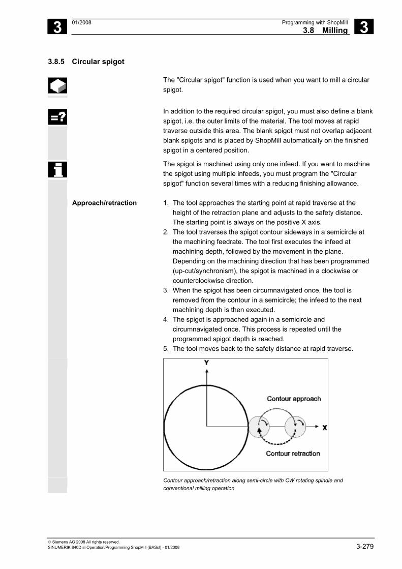
3 01/2008 Programming with ShopMill3.8 Milling
3
© Siemens AG 2008 All rights reserved. SINUMERIK 840D sl Operation/Programming ShopMill (BASsl) - 01/2008 3-279
3.8.5 Circular spigot
The "Circular spigot" function is used when you want to mill a circular spigot.
In addition to the required circular spigot, you must also define a blank
spigot, i.e. the outer limits of the material. The tool moves at rapid traverse outside this area. The blank spigot must not overlap adjacent blank spigots and is placed by ShopMill automatically on the finished spigot in a centered position.
The spigot is machined using only one infeed. If you want to machine the spigot using multiple infeeds, you must program the "Circular spigot" function several times with a reducing finishing allowance.
Approach/retraction 1. The tool approaches the starting point at rapid traverse at the height of the retraction plane and adjusts to the safety distance. The starting point is always on the positive X axis.
2. The tool traverses the spigot contour sideways in a semicircle at the machining feedrate. The tool first executes the infeed at machining depth, followed by the movement in the plane. Depending on the machining direction that has been programmed (up-cut/synchronism), the spigot is machined in a clockwise or counterclockwise direction.
3. When the spigot has been circumnavigated once, the tool is removed from the contour in a semicircle; the infeed to the next machining depth is then executed.
4. The spigot is approached again in a semicircle and circumnavigated once. This process is repeated until the programmed spigot depth is reached.
5. The tool moves back to the safety distance at rapid traverse.
Contour approach/retraction along semi-circle with CW rotating spindle and conventional milling operation
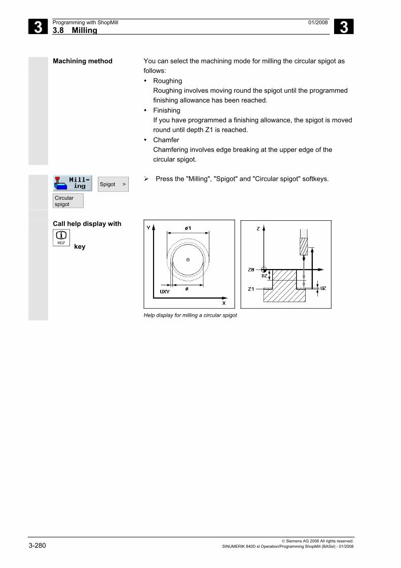
3 Programming with ShopMill 01/2008 3.8 Milling
3
© Siemens AG 2008 All rights reserved. 3-280 SINUMERIK 840D sl Operation/Programming ShopMill (BASsl) - 01/2008
Machining method You can select the machining mode for milling the circular spigot as follows: • Roughing
Roughing involves moving round the spigot until the programmed finishing allowance has been reached.
• Finishing If you have programmed a finishing allowance, the spigot is moved round until depth Z1 is reached.
• Chamfer Chamfering involves edge breaking at the upper edge of the circular spigot.
Spigot >
Circularspigot
Press the "Milling", "Spigot" and "Circular spigot" softkeys.
Call help display with
key
Help display for milling a circular spigot
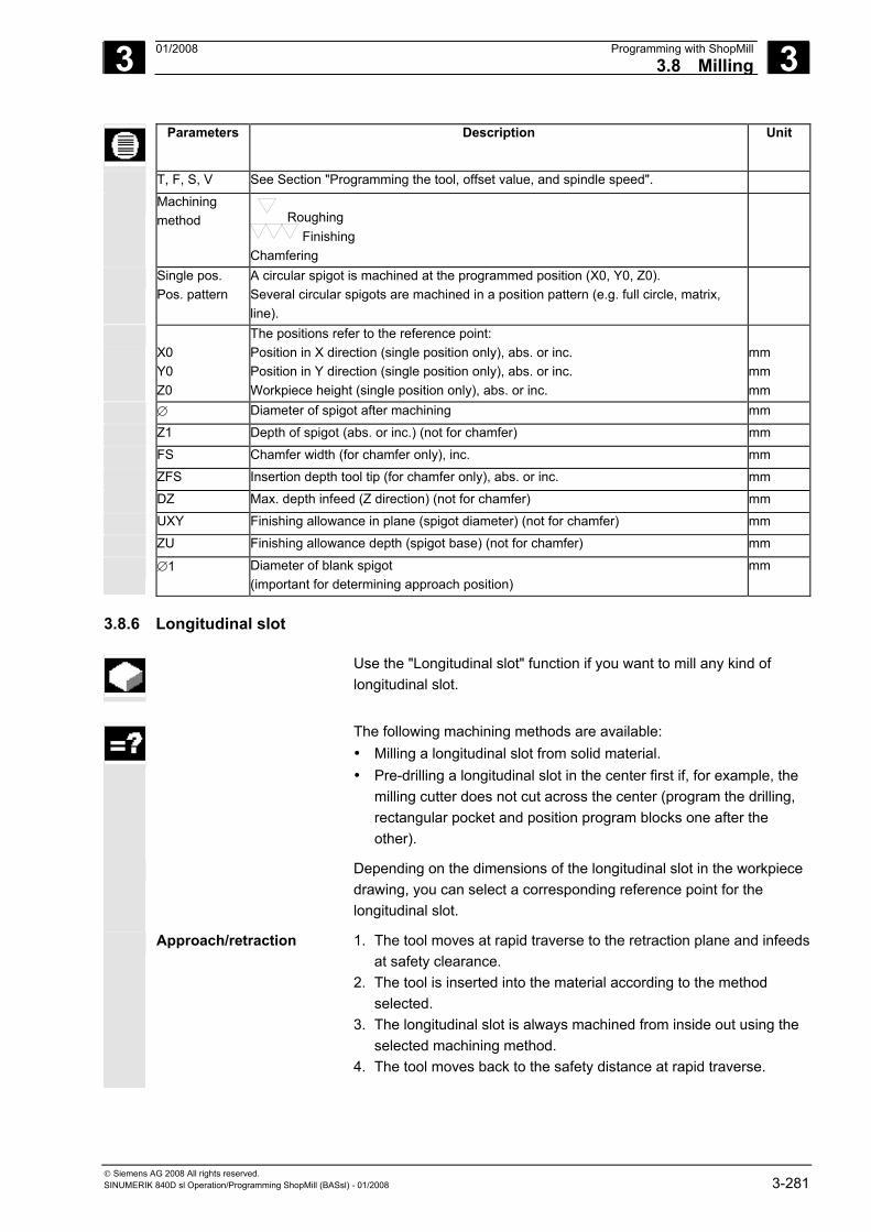
3 01/2008 Programming with ShopMill3.8 Milling
3
© Siemens AG 2008 All rights reserved. SINUMERIK 840D sl Operation/Programming ShopMill (BASsl) - 01/2008 3-281
Parameters Description Unit
T, F, S, V See Section "Programming the tool, offset value, and spindle speed".
Machining method Roughing
Finishing Chamfering
Single pos. Pos. pattern
A circular spigot is machined at the programmed position (X0, Y0, Z0). Several circular spigots are machined in a position pattern (e.g. full circle, matrix, line).
X0 Y0 Z0
The positions refer to the reference point: Position in X direction (single position only), abs. or inc. Position in Y direction (single position only), abs. or inc. Workpiece height (single position only), abs. or inc.
mm mm mm
∅ Diameter of spigot after machining mm
Z1 Depth of spigot (abs. or inc.) (not for chamfer) mm
FS Chamfer width (for chamfer only), inc. mm
ZFS Insertion depth tool tip (for chamfer only), abs. or inc. mm
DZ Max. depth infeed (Z direction) (not for chamfer) mm
UXY Finishing allowance in plane (spigot diameter) (not for chamfer) mm
ZU Finishing allowance depth (spigot base) (not for chamfer) mm
∅1 Diameter of blank spigot (important for determining approach position)
mm
3.8.6 Longitudinal slot
Use the "Longitudinal slot" function if you want to mill any kind of longitudinal slot.
The following machining methods are available:
• Milling a longitudinal slot from solid material. • Pre-drilling a longitudinal slot in the center first if, for example, the
milling cutter does not cut across the center (program the drilling, rectangular pocket and position program blocks one after the other).
Depending on the dimensions of the longitudinal slot in the workpiece drawing, you can select a corresponding reference point for the longitudinal slot.
Approach/retraction 1. The tool moves at rapid traverse to the retraction plane and infeeds at safety clearance.
2. The tool is inserted into the material according to the method selected.
3. The longitudinal slot is always machined from inside out using the selected machining method.
4. The tool moves back to the safety distance at rapid traverse.
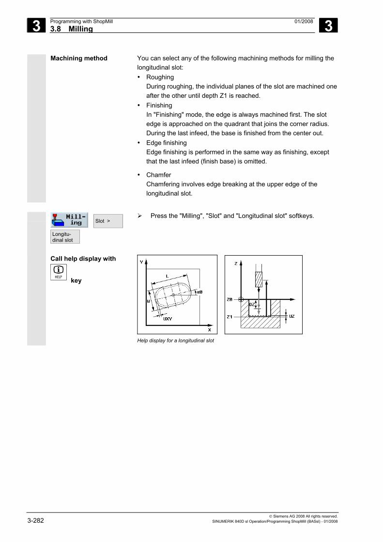
3 Programming with ShopMill 01/2008 3.8 Milling
3
© Siemens AG 2008 All rights reserved. 3-282 SINUMERIK 840D sl Operation/Programming ShopMill (BASsl) - 01/2008
Machining method You can select any of the following machining methods for milling the longitudinal slot: • Roughing
During roughing, the individual planes of the slot are machined one after the other until depth Z1 is reached.
• Finishing In "Finishing" mode, the edge is always machined first. The slot edge is approached on the quadrant that joins the corner radius. During the last infeed, the base is finished from the center out.
• Edge finishing Edge finishing is performed in the same way as finishing, except that the last infeed (finish base) is omitted.
• Chamfer Chamfering involves edge breaking at the upper edge of the longitudinal slot.
Slot >
Longitu-dinal slot
Press the "Milling", "Slot" and "Longitudinal slot" softkeys.
Call help display with
key
Help display for a longitudinal slot
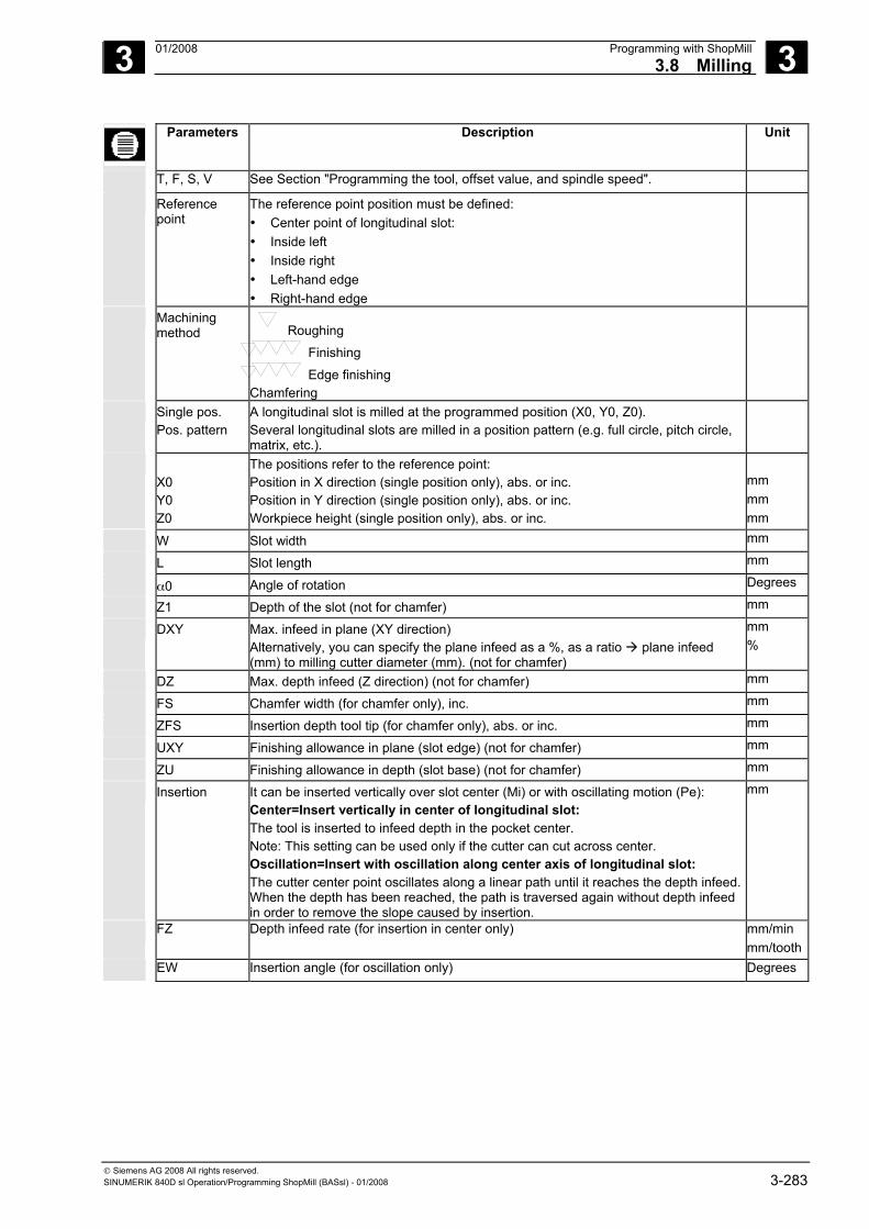
3 01/2008 Programming with ShopMill3.8 Milling
3
© Siemens AG 2008 All rights reserved. SINUMERIK 840D sl Operation/Programming ShopMill (BASsl) - 01/2008 3-283
Parameters Description Unit
T, F, S, V See Section "Programming the tool, offset value, and spindle speed".
Reference point
The reference point position must be defined: • Center point of longitudinal slot: • Inside left • Inside right • Left-hand edge • Right-hand edge
Machining method Roughing
Finishing
Edge finishing Chamfering
Single pos. Pos. pattern
A longitudinal slot is milled at the programmed position (X0, Y0, Z0). Several longitudinal slots are milled in a position pattern (e.g. full circle, pitch circle, matrix, etc.).
X0 Y0 Z0
The positions refer to the reference point: Position in X direction (single position only), abs. or inc. Position in Y direction (single position only), abs. or inc. Workpiece height (single position only), abs. or inc.
mm mm mm
W Slot width mm
L Slot length mm
α0 Angle of rotation Degrees Z1 Depth of the slot (not for chamfer) mm
DXY Max. infeed in plane (XY direction) Alternatively, you can specify the plane infeed as a %, as a ratio plane infeed (mm) to milling cutter diameter (mm). (not for chamfer)
mm %
DZ Max. depth infeed (Z direction) (not for chamfer) mm
FS Chamfer width (for chamfer only), inc. mm
ZFS Insertion depth tool tip (for chamfer only), abs. or inc. mm
UXY Finishing allowance in plane (slot edge) (not for chamfer) mm
ZU Finishing allowance in depth (slot base) (not for chamfer) mm
Insertion It can be inserted vertically over slot center (Mi) or with oscillating motion (Pe): Center=Insert vertically in center of longitudinal slot: The tool is inserted to infeed depth in the pocket center. Note: This setting can be used only if the cutter can cut across center. Oscillation=Insert with oscillation along center axis of longitudinal slot: The cutter center point oscillates along a linear path until it reaches the depth infeed. When the depth has been reached, the path is traversed again without depth infeed in order to remove the slope caused by insertion.
mm
FZ Depth infeed rate (for insertion in center only) mm/min mm/tooth
EW Insertion angle (for oscillation only) Degrees
3 Programming with ShopMill 01/2008 3.8 Milling
3
© Siemens AG 2008 All rights reserved. 3-284 SINUMERIK 840D sl Operation/Programming ShopMill (BASsl) - 01/2008
3.8.7 Circumferential slot
The "Circumferential slot" function is used when you want to mill one or more circumferential slots of the same size in a full circle or pitch circle.
Tool size Please note that there is a minimum size for the milling cutter used to
machine the circumferential slot: • Roughing:
½ slot width W – finishing allowance UXY ≤ milling cutter diameter• Finishing:
½ slot width W ≤ cutter diameter • Edge finishing:
Finishing allowance UXY ≤ milling cutter diameter
Annular slot
To create an annular slot, you must enter the following values for the "Number N" and "Aperture angle α1" parameters: N = 1 α1 = 360°
Approach/retraction 1. At the height of the retraction plane, the tool approaches the center point of the semicircle at the end of the slot at rapid traverse and adjusts to the safety distance.
2. Then, the tool enters the workpiece at machining infeed (taking into consideration the maximum infeed in the Z direction and the finishing allowance). Depending on the machining direction (up-cut or synchronism), the circumferential slot is machined in a clockwise or counterclockwise direction.
3. When the first circumferential slot is finished, the tool moves to the retraction plane at rapid traverse.
4. The next circumferential slot is approached along a straight line or circular path and then machined.
5. The tool moves back to the safety distance at rapid traverse.
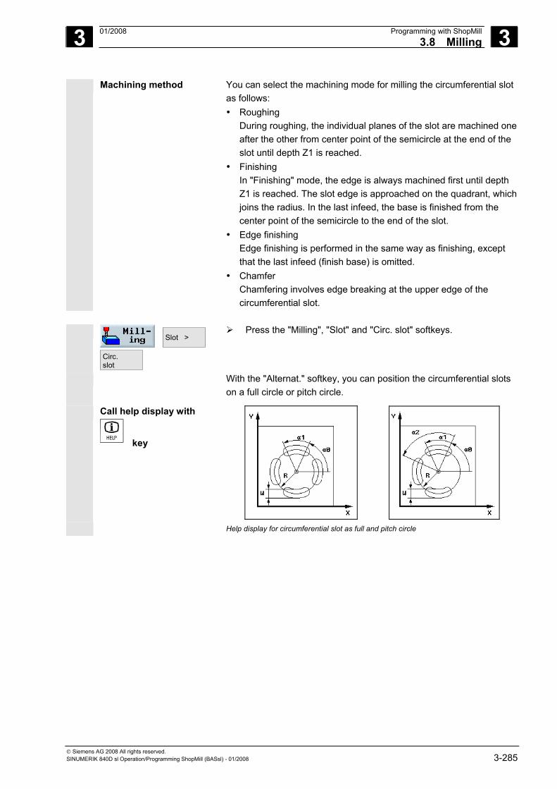
3 01/2008 Programming with ShopMill3.8 Milling
3
© Siemens AG 2008 All rights reserved. SINUMERIK 840D sl Operation/Programming ShopMill (BASsl) - 01/2008 3-285
Machining method You can select the machining mode for milling the circumferential slot as follows: • Roughing
During roughing, the individual planes of the slot are machined one after the other from center point of the semicircle at the end of the slot until depth Z1 is reached.
• Finishing In "Finishing" mode, the edge is always machined first until depth Z1 is reached. The slot edge is approached on the quadrant, which joins the radius. In the last infeed, the base is finished from the center point of the semicircle to the end of the slot.
• Edge finishing Edge finishing is performed in the same way as finishing, except that the last infeed (finish base) is omitted.
• Chamfer Chamfering involves edge breaking at the upper edge of the circumferential slot.
Slot >
Circ. slot
Press the "Milling", "Slot" and "Circ. slot" softkeys.
With the "Alternat." softkey, you can position the circumferential slots on a full circle or pitch circle.
Call help display with
key
Help display for circumferential slot as full and pitch circle
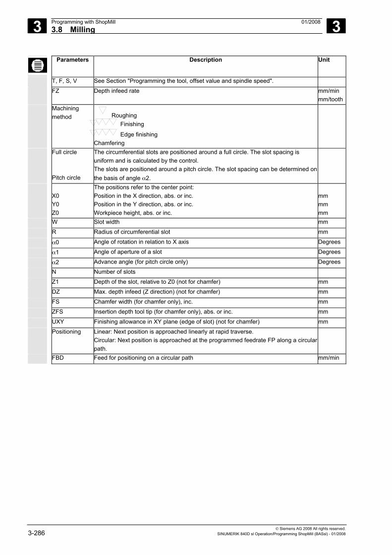
3 Programming with ShopMill 01/2008 3.8 Milling
3
© Siemens AG 2008 All rights reserved. 3-286 SINUMERIK 840D sl Operation/Programming ShopMill (BASsl) - 01/2008
Parameters Description Unit
T, F, S, V See Section "Programming the tool, offset value and spindle speed".
FZ Depth infeed rate mm/min mm/tooth
Machining method Roughing
Finishing
Edge finishing Chamfering
Full circle Pitch circle
The circumferential slots are positioned around a full circle. The slot spacing is uniform and is calculated by the control. The slots are positioned around a pitch circle. The slot spacing can be determined on the basis of angle α2.
X0 Y0 Z0
The positions refer to the center point: Position in the X direction, abs. or inc. Position in the Y direction, abs. or inc. Workpiece height, abs. or inc.
mm mm mm
W Slot width mm
R Radius of circumferential slot mm
α0 Angle of rotation in relation to X axis Degrees α1 Angle of aperture of a slot Degrees α2 Advance angle (for pitch circle only) Degrees N Number of slots
Z1 Depth of the slot, relative to Z0 (not for chamfer) mm
DZ Max. depth infeed (Z direction) (not for chamfer) mm
FS Chamfer width (for chamfer only), inc. mm
ZFS Insertion depth tool tip (for chamfer only), abs. or inc. mm
UXY Finishing allowance in XY plane (edge of slot) (not for chamfer) mm
Positioning Linear: Next position is approached linearly at rapid traverse. Circular: Next position is approached at the programmed feedrate FP along a circular path.
FBD Feed for positioning on a circular path mm/min
3 01/2008 Programming with ShopMill3.8 Milling
3
© Siemens AG 2008 All rights reserved. SINUMERIK 840D sl Operation/Programming ShopMill (BASsl) - 01/2008 3-287
3.8.8 Open slot
Use the "Open slot" function if you want to machine open slots.
You can choose between the following machining strategies, depending on your workpiece and machine properties: • Vortex milling • Plunge cutting
Vortex milling
Particularly where hardened materials are concerned, this process is used for roughing and contour preparation with coated VHM milling cutters. Vortex milling is the preferred technique for HSC roughing, as it ensures that the tool is never completely inserted. This means that the level of overlap set is adhered to exactly.
Supplementary conditions for vortex milling
• Roughing 1/2 slot width W – finishing allowance UXY ≤ milling cutter diameter
• Finishing 1/2 slot width W ≤ milling cutter diameter
• Edge finishing Finishing allowance UXY ≤ milling cutter diameter
• Slot width Minimum 1.15 x milling cutter diameter + finishing allowance Maximum 2 x milling cutter diameter + 2 x finishing allowance
• Radial infeed Minimum 0.02 x milling cutter diameter Maximum 0.25 x milling cutter diameter
• Maximum infeed depth ≤ section height of milling cutter
Please note that the section height of the milling cutter cannot be checked. The maximum radial infeed is dependent on the milling cutter. For hard materials, use a smaller infeed.
3 Programming with ShopMill 01/2008 3.8 Milling
3
© Siemens AG 2008 All rights reserved. 3-288 SINUMERIK 840D sl Operation/Programming ShopMill (BASsl) - 01/2008
Approach/retraction 1. The tool approaches the starting point in front of the slot at rapid traverse and remains at the safety distance.
2. The tool adjusts to the cutting depth. 3. The open slot is always machined along its entire length, using the
selected machining method. 4. The tool moves back to the safety distance at rapid traverse.
Machining method You can select any of the following machining methods for machining open slots:
• Roughing takes place by directing the milling cutter along a circular path. While in motion, the milling cutter is continuously fed more and more in the plane. If the milling cutter has traveled through the entire slot, it travels back to the starting point using circular movements. By doing this, it removes the next layer (infeed depth) in the "Z direction". This process is repeated until the set slot depth plus the finishing allowance has been achieved.
• When finishing walls, the milling cutter travels along the slot walls: to do this, it is again fed in the Z direction, unit by unit. In doing this, the milling cutter travels along the safety distance beyond the beginning and end of the slot, so that it can guarantee an even slot wall surface across the entire length of the slot.
• Edge finishing Edge finishing is performed in the same way as finishing, except that the last infeed (finish base) is omitted.
• Base finishing When finishing the base, the milling cutter executes one motion across the finished slot and back again.
• Rough finishing If there is too much residual material on the slot walls, unwanted corners are removed to the finishing dimension level.
• Chamfering Chamfering involves edge breaking at the upper edge of the slot.
Plunge cutting Plunge cutting is the preferred method of machining pockets and slots for "unstable" machines and workpiece geometries.
This method generally only exerts forces along the tool axis, i.e., perpendicular to the surface of the pocket/slot to be machined (with XY plane, in Z direction).
For this reason, the tool is subject to virtually no deformation. Thanks to the axial loading of the tool, there is hardly any danger of vibrations affecting unstable workpieces.
The depth of cut can be increased considerably. The plunge cutter, as it is known, ensures a longer service life due to fewer vibrations occurring with long collar lengths.
3 01/2008 Programming with ShopMill3.8 Milling
3
© Siemens AG 2008 All rights reserved. SINUMERIK 840D sl Operation/Programming ShopMill (BASsl) - 01/2008 3-289
Supplementary conditions for plunge cutting
• Maximum radial infeed The maximum radial infeed is dependent on the width of the milling cutter’s cutting edge.
• Increment The lateral increment is calculated on the basis of the required slot width, the milling cutter diameter and the finishing allowance.
• Return Returning involves the milling cutter being retracted at a 45° angle following insertion, if the wrap angle is less than 180°. Otherwise, retraction is vertical, as is the case with boring.
• Retraction Retraction is performed perpendicular to the wrapped surface.
• Safety distance The milling cutter motion travels beyond the end of the workpiece, along the length of the safety distance, to avoid rounding of the slot walls at the ends.
Please note that the width of the milling cutter's cutting edge cannot be checked for the maximum radial infeed.
Approach/retraction 1. The tool moves at rapid traverse to the starting point in front of the slot and stops at the safety distance.
2. The open slot is always machined along its entire length, using the selected machining method.
3. The tool moves back to the safety distance at rapid traverse. Machining method You can select any of the following machining methods for machining
open slots:
• Roughing Roughing of the slot takes place sequentially along the length of the slot, with the milling cutter performing vertical insertions at the machining feedrate. The milling cutter is then retracted and repositioned at the next insertion point. The milling cutter moves along the length of the groove, at half the infeed rate, and inserts alternately at the left-hand and right-hand wall. The first insertion takes place at the groove edge, with the milling cutter inserted at half the infeed, less the safety clearance (if the safety clearance is greater than the infeed, this will be on the outside). For this cycle, the maximum width of the grooves must be less than double the width of the milling cutter, plus the finishing allowance. Following each insertion, the milling cutter is lifted by the height of the safety clearance at the machining feedrate. As far as possible, this occurs during what is known as the retraction process, i.e., if the milling cutter's wrap angle is less than 180°, it is lifted at a 45° angle from the base in the opposite direction to the bisector of the wrap area. The milling cutter then travels rapidly along the material.
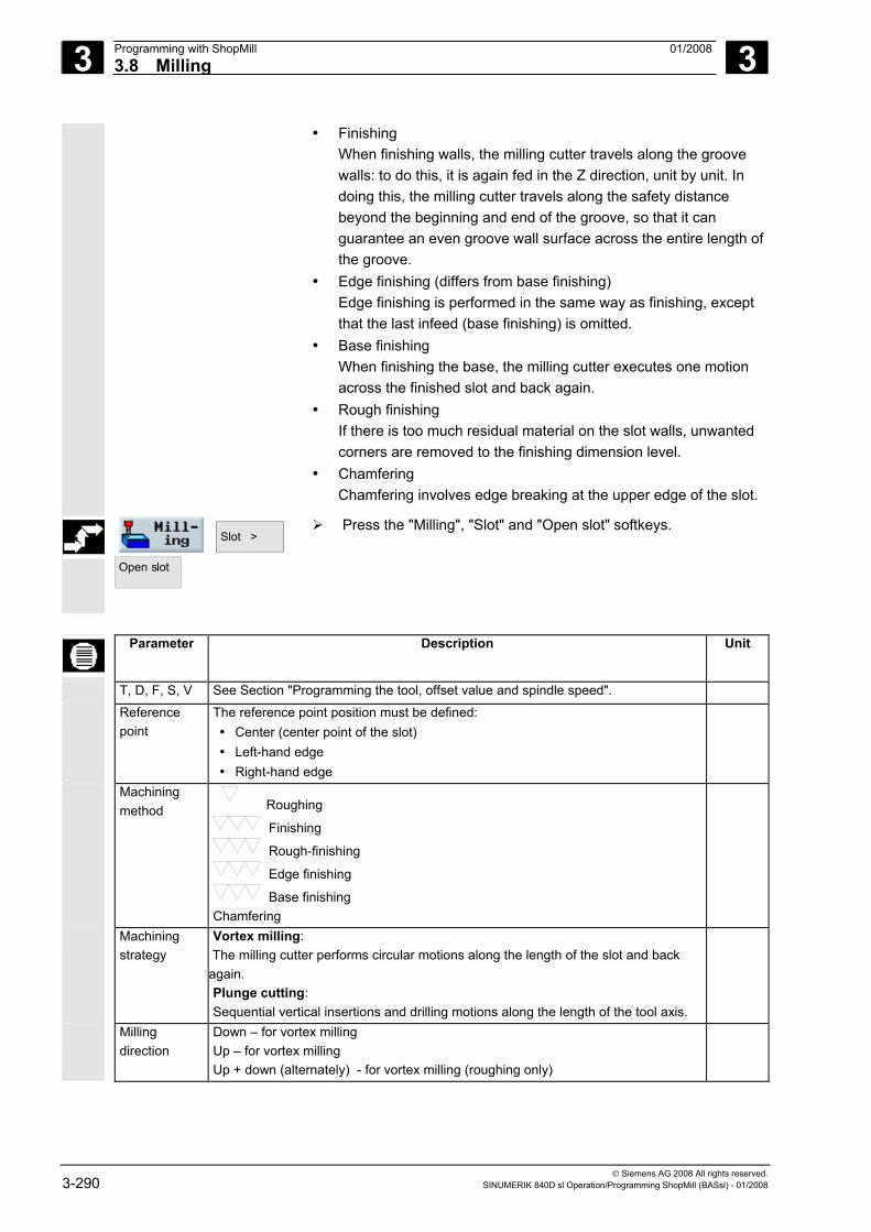
3 Programming with ShopMill 01/2008 3.8 Milling
3
© Siemens AG 2008 All rights reserved. 3-290 SINUMERIK 840D sl Operation/Programming ShopMill (BASsl) - 01/2008
• Finishing When finishing walls, the milling cutter travels along the groove walls: to do this, it is again fed in the Z direction, unit by unit. In doing this, the milling cutter travels along the safety distance beyond the beginning and end of the groove, so that it can guarantee an even groove wall surface across the entire length of the groove.
• Edge finishing (differs from base finishing) Edge finishing is performed in the same way as finishing, except that the last infeed (base finishing) is omitted.
• Base finishing When finishing the base, the milling cutter executes one motion across the finished slot and back again.
• Rough finishing If there is too much residual material on the slot walls, unwanted corners are removed to the finishing dimension level.
• Chamfering Chamfering involves edge breaking at the upper edge of the slot.
Slot >
Open slot
Press the "Milling", "Slot" and "Open slot" softkeys.
Parameter Description Unit
T, D, F, S, V See Section "Programming the tool, offset value and spindle speed".
Reference point
The reference point position must be defined: • Center (center point of the slot) • Left-hand edge • Right-hand edge
Machining method Roughing
Finishing
Rough-finishing
Edge finishing
Base finishing Chamfering
Machining strategy
Vortex milling: The milling cutter performs circular motions along the length of the slot and back again. Plunge cutting: Sequential vertical insertions and drilling motions along the length of the tool axis.
Milling direction
Down – for vortex milling Up – for vortex milling Up + down (alternately) - for vortex milling (roughing only)
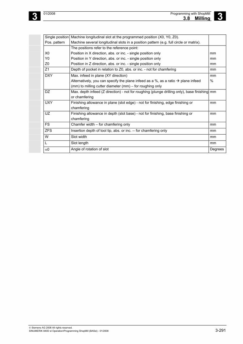
3 01/2008 Programming with ShopMill3.8 Milling
3
© Siemens AG 2008 All rights reserved. SINUMERIK 840D sl Operation/Programming ShopMill (BASsl) - 01/2008 3-291
Single position Pos. pattern
Machine longitudinal slot at the programmed position (X0, Y0, Z0). Machine several longitudinal slots in a position pattern (e.g. full circle or matrix).
X0 Y0 Z0
The positions refer to the reference point: Position in X direction, abs. or inc. - single position only Position in Y direction, abs. or inc. - single position only Position in Z direction, abs. or inc. - single position only
mm mm mm
Z1 Depth of pocket in relation to Z0, abs. or inc. - not for chamfering mm
DXY Max. infeed in plane (XY direction) Alternatively, you can specify the plane infeed as a %, as a ratio plane infeed (mm) to milling cutter diameter (mm) – for roughing only
mm %
DZ Max. depth infeed (Z direction) - not for roughing (plunge drilling only), base finishing or chamfering
mm
UXY Finishing allowance in plane (slot edge) - not for finishing, edge finishing or chamfering
mm
UZ Finishing allowance in depth (slot base) - not for finishing, base finishing or chamfering
mm
FS Chamfer width – for chamfering only mm
ZFS Insertion depth of tool tip, abs. or inc. -- for chamfering only mm
W Slot width mm
L Slot length mm
α0 Angle of rotation of slot Degrees
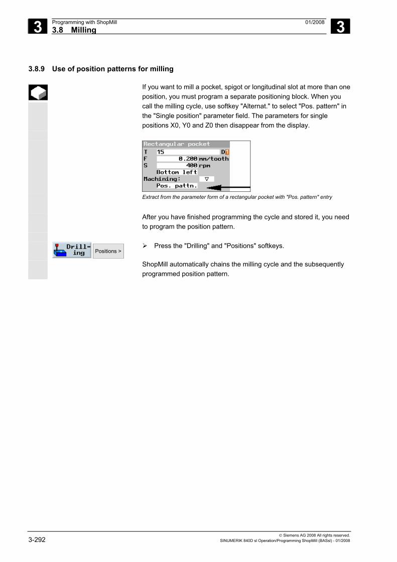
3 Programming with ShopMill 01/2008 3.8 Milling
3
© Siemens AG 2008 All rights reserved. 3-292 SINUMERIK 840D sl Operation/Programming ShopMill (BASsl) - 01/2008
3.8.9 Use of position patterns for milling
If you want to mill a pocket, spigot or longitudinal slot at more than oneposition, you must program a separate positioning block. When you call the milling cycle, use softkey "Alternat." to select "Pos. pattern" in the "Single position" parameter field. The parameters for single positions X0, Y0 and Z0 then disappear from the display.
Extract from the parameter form of a rectangular pocket with "Pos. pattern" entry After you have finished programming the cycle and stored it, you need
to program the position pattern.
Positions >
Press the "Drilling" and "Positions" softkeys.
ShopMill automatically chains the milling cycle and the subsequently programmed position pattern.
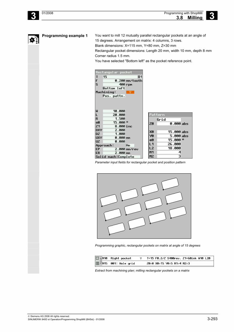
3 01/2008 Programming with ShopMill3.8 Milling
3
© Siemens AG 2008 All rights reserved. SINUMERIK 840D sl Operation/Programming ShopMill (BASsl) - 01/2008 3-293
Programming example 1 You want to mill 12 mutually parallel rectangular pockets at an angle of 15 degrees. Arrangement on matrix: 4 columns, 3 rows. Blank dimensions: X=115 mm, Y=80 mm, Z=30 mm Rectangular pocket dimensions: Length 20 mm, width 10 mm, depth 8 mm Corner radius 1.5 mm. You have selected "Bottom left" as the pocket reference point.
Parameter input fields for rectangular pocket and position pattern
Programming graphic, rectangular pockets on matrix at angle of 15 degrees
Extract from machining plan; milling rectangular pockets on a matrix
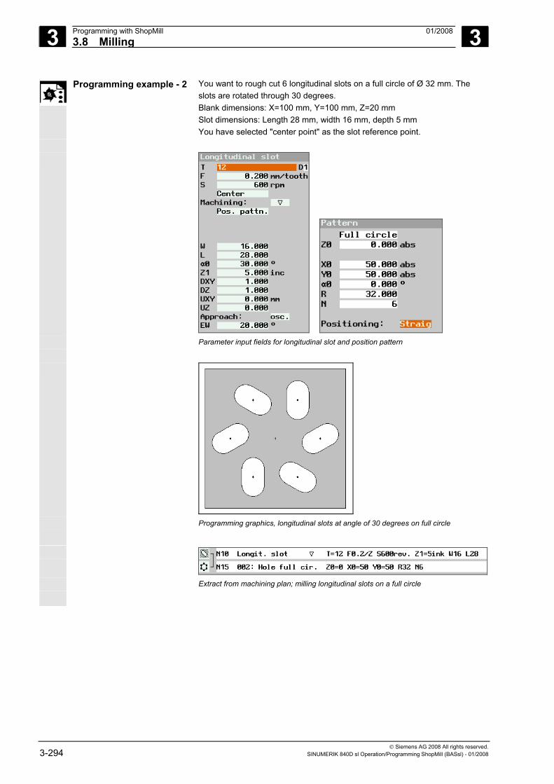
3 Programming with ShopMill 01/2008 3.8 Milling
3
© Siemens AG 2008 All rights reserved. 3-294 SINUMERIK 840D sl Operation/Programming ShopMill (BASsl) - 01/2008
Programming example - 2 You want to rough cut 6 longitudinal slots on a full circle of Ø 32 mm. The slots are rotated through 30 degrees. Blank dimensions: X=100 mm, Y=100 mm, Z=20 mm Slot dimensions: Length 28 mm, width 16 mm, depth 5 mm You have selected "center point" as the slot reference point.
Parameter input fields for longitudinal slot and position pattern
Programming graphics, longitudinal slots at angle of 30 degrees on full circle
Extract from machining plan; milling longitudinal slots on a full circle
3 01/2008 Programming with ShopMill3.8 Milling
3
© Siemens AG 2008 All rights reserved. SINUMERIK 840D sl Operation/Programming ShopMill (BASsl) - 01/2008 3-295
3.8.10 Engraving
The "Engraving" function is used to engrave a text on a workpiece along a line or arc. You can enter the text directly in the text field as "fixed text" or assign it via a variable as "variable text".
ShopMill uses a proportional font for engraving, i.e. the width of the
individual characters varies.
Approach/retraction 1. The tool approaches the starting point at rapid traverse at the height of the retraction plane and adjusts to the safety distance.
2. The tool moves to the machining depth Z1 at the infeed feedrate FZ and mills the characters.
3. The tool retracts to the safety clearance at rapid traverse and moves along a straight line to the next character.
4. Steps 2 and 3 are repeated until the entire text has been milled.
Variable texts There are various ways of defining variable text: • Date and time
You can engrave workpieces with the production date and current time of day, for example. The values for date and time are read from the NCK.
• Workpiece count Using the workpiece variables you can assign a consecutive number to the workpieces. You can define the format (number of digits, leading zeroes). The "workpiece count" variable is defined as a user variable (_E_PART[0]) in the GUD 7 data block. The place holder (#) is used to format the number of digits at which the workpiece counts output will begin.
If you output the workpiece count 1 for the first workpiece, you can specify an additive value (e.g., <#,_E_PART[0] + 100>). The workpiece count output is then incremented by this value (e.g. 101, 102, 103,...).
• Numbers When outputting number (e.g. measurement results), you can select the output format (digits either side of the point) of the number to be engraved.
• Text Instead of entering a fixed text in the engraving text field, you can specify the text to be engraved via a text variable (e.g., _VAR_TEXT=“ABC123“).
3 Programming with ShopMill 01/2008 3.8 Milling
3
© Siemens AG 2008 All rights reserved. 3-296 SINUMERIK 840D sl Operation/Programming ShopMill (BASsl) - 01/2008
Mirror writing
If you want to engrave mirror writing, first program the mirroring (see Section "Defining coordinate transformations" and then enter the text in the "Engraving" function.
Full circle If you want to distribute the characters evenly around a full circle, enter the arc angle α2=360°. ShopMill then distributes the characters evenly around the full circle.
Engraving
> Press the "Milling" and "Engraving" softkeys.
Lowercase letters Lowercase
Press the "Lowercase" softkey to enter lowercase letters.
Press it again to enter uppercase letters.
Special characters Special
characters Press the "Special characters" softkey if you need a character that
does not appear on the input keys.
The "Special characters" window appears.
Place the cursor on the character you require.
Press the "OK" softkey.
The selected character is inserted into the text at the cursor position.
Entering a date Variable >
Date
Press the "Variable" and "Date" softkeys if you want to engrave the current date.
The data is inserted in the European date format (<DD>.<MM>.<YYYY>).
To obtain a different date format, you must adapt the format specified in the text field. For example, to engrave the date in the American dateformat (month/day/year => 8/16/04), change the format to <M>/<D>/<YY> .
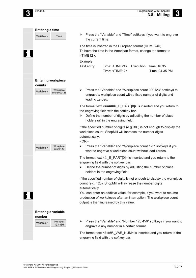
3 01/2008 Programming with ShopMill3.8 Milling
3
© Siemens AG 2008 All rights reserved. SINUMERIK 840D sl Operation/Programming ShopMill (BASsl) - 01/2008 3-297
Entering a time Variable >
Time
Press the "Variable" and "Time" softkeys if you want to engrave
the current time.
The time is inserted in the European format (<TIME24>). To have the time in the American format, change the format to
<TIME12>.
Example: Text entry: Time: <TIME24> Execution: Time: 16.35 Time: <TIME12> Time: 04.35 PM
Entering workpiece
counts
Variable >
Workpiece count 000123
Press the "Variable" and "Workpiece count 000123" softkeys to engrave a workpiece count with a fixed number of digits and leading zeroes.
The format text <######,_E_PART[0]> is inserted and you return to the engraving field with the softkey bar.
Define the number of digits by adjusting the number of place holders (#) in the engraving field.
If the specified number of digits (e.g. ## ) is not enough to display the workpiece count, ShopMill will increase the number digits automatically.
- OR - Variable >
Workpiece count 123
Press the "Variable" and "Workpiece count 123" softkeys if you want to engrave a workpiece count without lead zeroes.
The format text <#,_E_PART[0]> is inserted and you return to the engraving field with the softkey bar.
Define the number of digits by adjusting the number of place holders in the engraving field.
If the specified number of digits is not enough to display the workpiece count (e.g. 123), ShopMill will increase the number digits automatically.
You can enter an additive value, for example, if you want to resume production of workpieces after an interruption. The workpiece count output is then increased by this value.
Entering a variable
number
Variable >
Number 123.456
Press the "Variable" and "Number 123.456" softkeys if you want to engrave a any number in a certain format.
The format text <#.###,_VAR_NUM> is inserted and you return to the engraving field with the softkey bar.
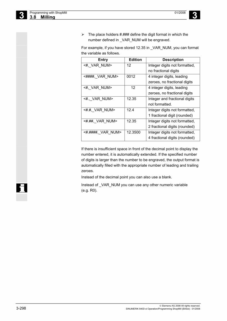
3 Programming with ShopMill 01/2008 3.8 Milling
3
© Siemens AG 2008 All rights reserved. 3-298 SINUMERIK 840D sl Operation/Programming ShopMill (BASsl) - 01/2008
The place holders #.### define the digit format in which the number defined in _VAR_NUM will be engraved.
For example, if you have stored 12.35 in _VAR_NUM, you can format the variable as follows.
Entry Edition Description <#,_VAR_NUM> 12 Integer digits not formatted,
no fractional digits <####,_VAR_NUM> 0012 4 integer digits, leading
zeroes, no fractional digits <#,_VAR_NUM> 12 4 integer digits, leading
zeroes, no fractional digits <#.,_VAR_NUM> 12.35 Integer and fractional digits
not formatted. <#.#,_VAR_NUM> 12.4 Integer digits not formatted,
1 fractional digit (rounded) <#.##,_VAR_NUM> 12.35 Integer digits not formatted,
2 fractional digits (rounded) <#.####,_VAR_NUM> 12.3500 Integer digits not formatted,
4 fractional digits (rounded) If there is insufficient space in front of the decimal point to display the
number entered, it is automatically extended. If the specified number of digits is larger than the number to be engraved, the output format is automatically filled with the appropriate number of leading and trailing zeroes. Instead of the decimal point you can also use a blank.
Instead of _VAR_NUM you can use any other numeric variable (e.g. R0).
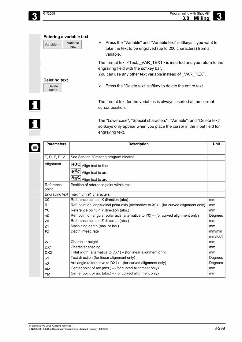
3 01/2008 Programming with ShopMill3.8 Milling
3
© Siemens AG 2008 All rights reserved. SINUMERIK 840D sl Operation/Programming ShopMill (BASsl) - 01/2008 3-299
Entering a variable text Variable >
Variable
text Press the "Variable" and "Variable text" softkeys if you want to
take the text to be engraved (up to 200 characters) from a variable.
The format text <Text, _VAR_TEXT> is inserted and you return to the engraving field with the softkey bar.
You can use any other text variable instead of _VAR_TEXT. Deleting text Delete
text > Press the "Delete text" softkey to delete the entire text.
The format text for the variables is always inserted at the current
cursor position.
The "Lowercase", "Special characters", "Variable", and "Delete text"
softkeys only appear when you place the cursor in the input field for engraving text.
Parameters Description Unit
T, D, F, S, V See Section "Creating program blocks".
Alignment Align text to line
Align text to arc
Align text to arc
Reference point
Position of reference point within text
Engraving text maximum 91 characters
X0 R Y0 α0 Z0 Z1 FZ W DX1 DX2 α1 α2 XM YM
Reference point in X direction (abs) Ref. point on longitudinal polar axis (alternative to X0) – (for curved alignment only) Reference point in Y direction (abs.) Ref. point on angular polar axis (alternative to Y0) – (for curved alignment only) Reference point in Z direction (abs.) Machining depth (abs. or inc.) Depth infeed rate Character height Character spacing Total width (alternative to DX1) – (for linear alignment only) Text direction (for linear alignment only) Arc angle (alternative to DX1) – (for curved alignment only) Center point of arc (abs.) – (for curved alignment only) Center point of arc (abs.) – (for curved alignment only)
mm mm mm Degrees mm mm mm/min mm/toothmm mm mm Degrees Degrees mm mm
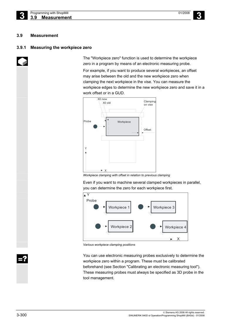
3 Programming with ShopMill 01/2008 3.9 Measurement
3
© Siemens AG 2008 All rights reserved. 3-300 SINUMERIK 840D sl Operation/Programming ShopMill (BASsl) - 01/2008
3.9 Measurement
3.9.1 Measuring the workpiece zero
The "Workpiece zero" function is used to determine the workpiece zero in a program by means of an electronic measuring probe.
For example, if you want to produce several workpieces, an offset may arise between the old and the new workpiece zero when clamping the next workpiece in the vise. You can measure the workpiece edges to determine the new workpiece zero and save it in a work offset or in a GUD.
Workpiece
Y
X
Probe
Clampingon vise
Offset
X0 newX0 old
Workpiece clamping with offset in relation to previous clamping
Even if you want to machine several clamped workpieces in parallel, you can determine the zero for each workpiece first.
Y
X
Probe
Workpiece 1
Workpiece 2 Workpiece 4
Workpiece 3
Various workpiece clamping positions
You can use electronic measuring probes exclusively to determine the workpiece zero within a program. These must be calibrated beforehand (see Section "Calibrating an electronic measuring tool"). These measuring probes must always be specified as 3D probe in the tool management.
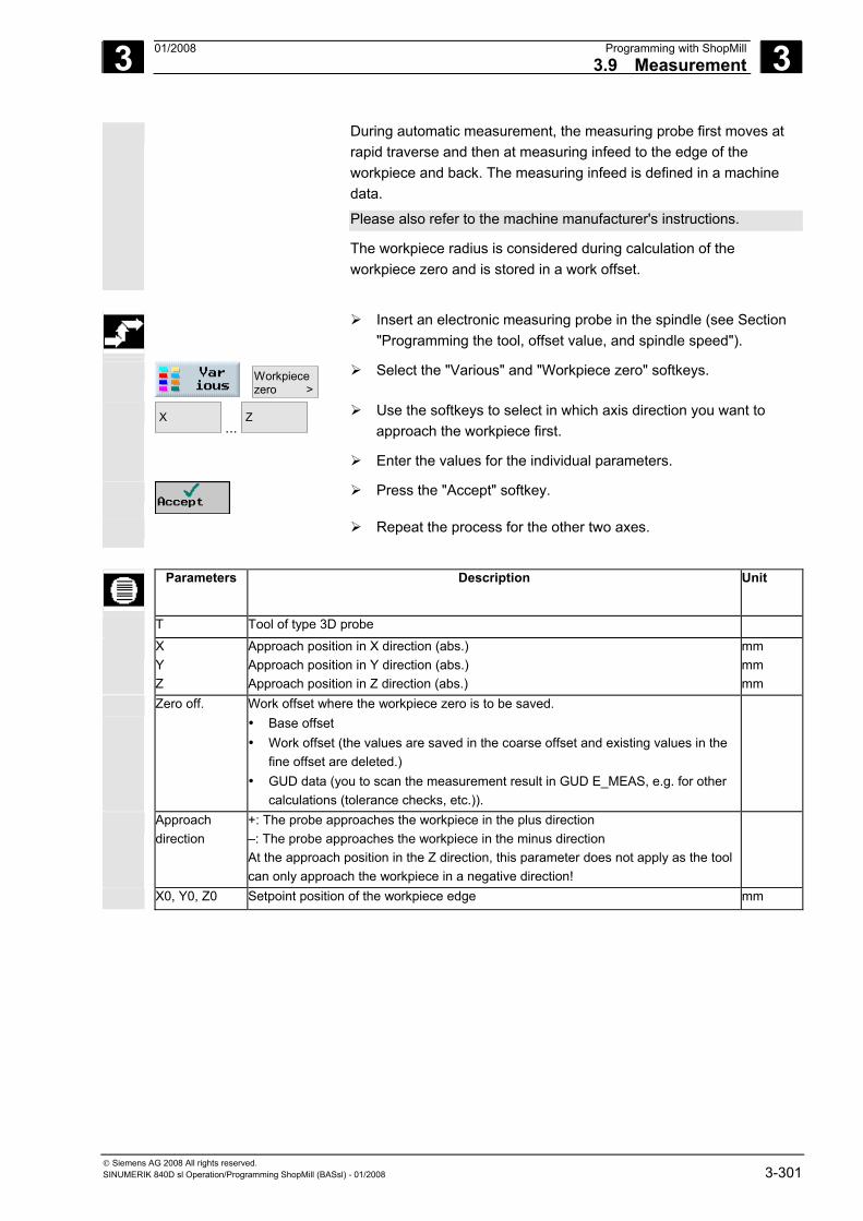
3 01/2008 Programming with ShopMill3.9 Measurement
3
© Siemens AG 2008 All rights reserved. SINUMERIK 840D sl Operation/Programming ShopMill (BASsl) - 01/2008 3-301
During automatic measurement, the measuring probe first moves at rapid traverse and then at measuring infeed to the edge of the workpiece and back. The measuring infeed is defined in a machine data.
Please also refer to the machine manufacturer's instructions.
The workpiece radius is considered during calculation of the workpiece zero and is stored in a work offset.
Insert an electronic measuring probe in the spindle (see Section
"Programming the tool, offset value, and spindle speed").
Workpiecezero >
Select the "Various" and "Workpiece zero" softkeys.
X ...
Z
Use the softkeys to select in which axis direction you want to approach the workpiece first.
Enter the values for the individual parameters.
Press the "Accept" softkey.
Repeat the process for the other two axes.
Parameters Description Unit
T Tool of type 3D probe
X Y Z
Approach position in X direction (abs.) Approach position in Y direction (abs.) Approach position in Z direction (abs.)
mm mm mm
Zero off. Work offset where the workpiece zero is to be saved. • Base offset • Work offset (the values are saved in the coarse offset and existing values in the
fine offset are deleted.) • GUD data (you to scan the measurement result in GUD E_MEAS, e.g. for other
calculations (tolerance checks, etc.)).
Approach direction
+: The probe approaches the workpiece in the plus direction –: The probe approaches the workpiece in the minus direction At the approach position in the Z direction, this parameter does not apply as the tool can only approach the workpiece in a negative direction!
X0, Y0, Z0 Setpoint position of the workpiece edge mm
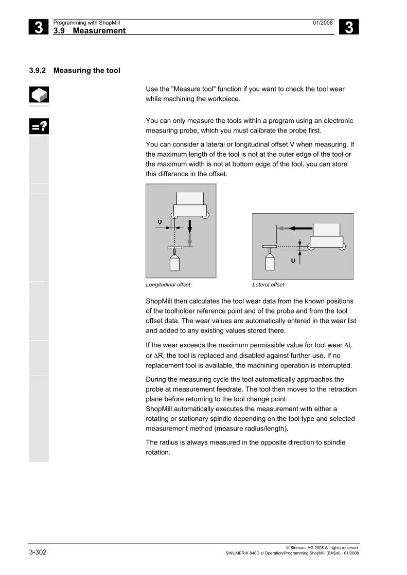
3 Programming with ShopMill 01/2008 3.9 Measurement
3
© Siemens AG 2008 All rights reserved. 3-302 SINUMERIK 840D sl Operation/Programming ShopMill (BASsl) - 01/2008
3.9.2 Measuring the tool
Use the "Measure tool" function if you want to check the tool wear while machining the workpiece.
You can only measure the tools within a program using an electronic
measuring probe, which you must calibrate the probe first.
You can consider a lateral or longitudinal offset V when measuring. If the maximum length of the tool is not at the outer edge of the tool or the maximum width is not at bottom edge of the tool, you can store this difference in the offset.
Longitudinal offset
Lateral offset
ShopMill then calculates the tool wear data from the known positions of the toolholder reference point and of the probe and from the tool offset data. The wear values are automatically entered in the wear list and added to any existing values stored there.
If the wear exceeds the maximum permissible value for tool wear ΔL or ΔR, the tool is replaced and disabled against further use. If no replacement tool is available, the machining operation is interrupted.
During the measuring cycle the tool automatically approaches the probe at measurement feedrate. The tool then moves to the retraction plane before returning to the tool change point. ShopMill automatically executes the measurement with either a rotating or stationary spindle depending on the tool type and selected measurement method (measure radius/length).
The radius is always measured in the opposite direction to spindle rotation.
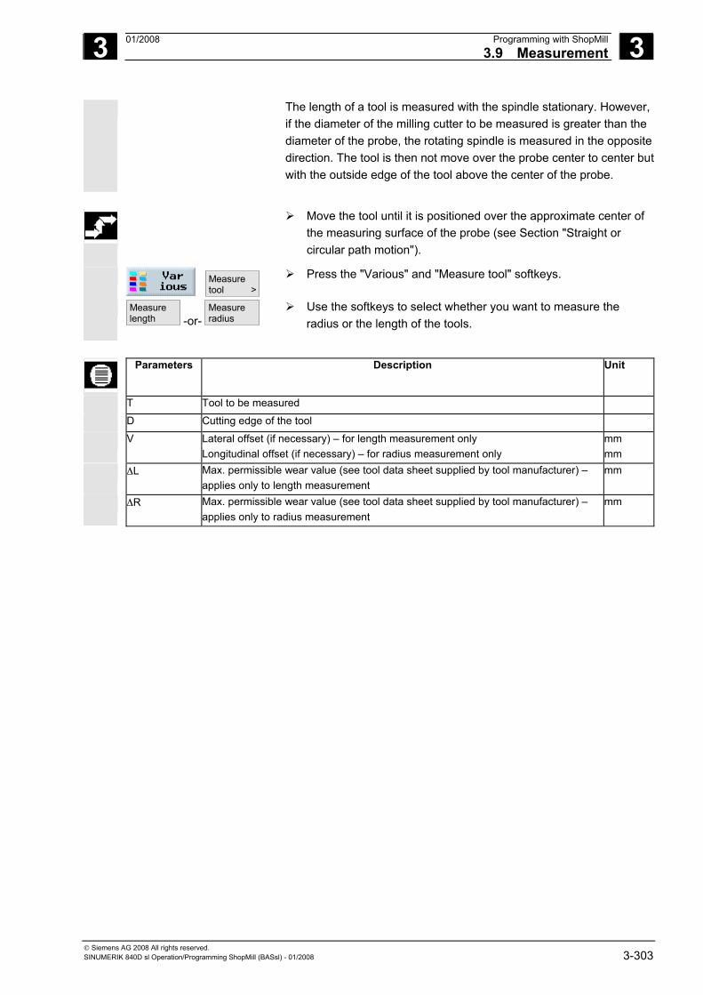
3 01/2008 Programming with ShopMill3.9 Measurement
3
© Siemens AG 2008 All rights reserved. SINUMERIK 840D sl Operation/Programming ShopMill (BASsl) - 01/2008 3-303
The length of a tool is measured with the spindle stationary. However, if the diameter of the milling cutter to be measured is greater than the diameter of the probe, the rotating spindle is measured in the opposite direction. The tool is then not move over the probe center to center butwith the outside edge of the tool above the center of the probe.
Move the tool until it is positioned over the approximate center of
the measuring surface of the probe (see Section "Straight or circular path motion").
Measuretool >
Press the "Various" and "Measure tool" softkeys.
Measurelength -or-
Measureradius
Use the softkeys to select whether you want to measure the radius or the length of the tools.
Parameters Description Unit
T Tool to be measured
D Cutting edge of the tool
V Lateral offset (if necessary) – for length measurement only Longitudinal offset (if necessary) – for radius measurement only
mm mm
ΔL Max. permissible wear value (see tool data sheet supplied by tool manufacturer) – applies only to length measurement
mm
ΔR Max. permissible wear value (see tool data sheet supplied by tool manufacturer) – applies only to radius measurement
mm
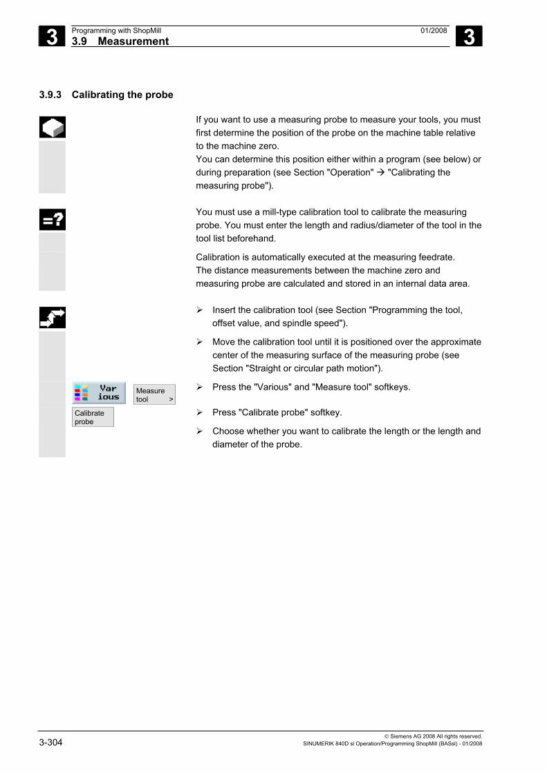
3 Programming with ShopMill 01/2008 3.9 Measurement
3
© Siemens AG 2008 All rights reserved. 3-304 SINUMERIK 840D sl Operation/Programming ShopMill (BASsl) - 01/2008
3.9.3 Calibrating the probe
If you want to use a measuring probe to measure your tools, you must first determine the position of the probe on the machine table relative to the machine zero. You can determine this position either within a program (see below) or during preparation (see Section "Operation" "Calibrating the measuring probe").
You must use a mill-type calibration tool to calibrate the measuring
probe. You must enter the length and radius/diameter of the tool in the tool list beforehand.
Calibration is automatically executed at the measuring feedrate. The distance measurements between the machine zero and measuring probe are calculated and stored in an internal data area.
Insert the calibration tool (see Section "Programming the tool,
offset value, and spindle speed").
Move the calibration tool until it is positioned over the approximate center of the measuring surface of the measuring probe (see Section "Straight or circular path motion").
Measuretool >
Press the "Various" and "Measure tool" softkeys.
Calibrateprobe
Press "Calibrate probe" softkey.
Choose whether you want to calibrate the length or the length and diameter of the probe.
3 01/2008 Programming with ShopMill3.10 Miscellaneous functions
3
© Siemens AG 2008 All rights reserved. SINUMERIK 840D sl Operation/Programming ShopMill (BASsl) - 01/2008 3-305
3.10 Miscellaneous functions
3.10.1 Calling a subroutine
If you require the same machining steps in the programming of different workpieces, you can define these machining steps in a separate routine. You can then call this subroutine in any programs. Identical machining steps therefore only have to be programmed once.
ShopMill does not differentiate between main program and subroutine.
This means that you can call a "standard" sequential control or G code program as subroutine in another sequential control program. In this subroutine, you can also call another subroutine. The maximum nesting depth is 8 subroutines. You cannot insert subroutines among blocks chained by the control.
If you want to call a sequential control program as a subroutine, the program must already have been calculated once (load or simulate program in Machine Auto mode). This is not necessary for G code subroutines.
The subroutine must always be stored in the NCK main memory (in a separate directory "XYZ" or in the "ShopMill", "Part programs", "Subroutines" directories).
If you want to call a subroutine located on another drive, you can use G code command "EXTCALL".
Example: Calling program "Form25_1.mpf" on the CompactFlash card of the ShopMill version on NCU (HMI Embedded): EXTCALL "C:\FORM25_1.MPF"
Please note that, when a subroutine is called, ShopMill evaluates the
settings in the program header of the subroutine. These settings also remain active even after the subroutine has ended. If you wish to activate the settings from the program header for the main program again, you can make the settings again in the main program after calling the subroutine (see Section "Changing program settings").
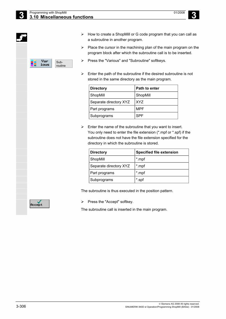
3 Programming with ShopMill 01/2008 3.10 Miscellaneous functions
3
© Siemens AG 2008 All rights reserved. 3-306 SINUMERIK 840D sl Operation/Programming ShopMill (BASsl) - 01/2008
How to create a ShopMill or G code program that you can call as a subroutine in another program.
Place the cursor in the machining plan of the main program on the program block after which the subroutine call is to be inserted.
Sub-routine
Press the "Various" and "Subroutine" softkeys.
Enter the path of the subroutine if the desired subroutine is not
stored in the same directory as the main program.
Directory Path to enter ShopMill ShopMill Separate directory XYZ XYZ Part programs MPF Subprograms SPF Enter the name of the subroutine that you want to insert.
You only need to enter the file extension (*.mpf or *.spf) if the subroutine does not have the file extension specified for the directory in which the subroutine is stored.
Directory Specified file extension ShopMill *.mpf Separate directory XYZ *.mpf Part programs *.mpf Subprograms *.spf The subroutine is thus executed in the position pattern.
Press the "Accept" softkey.
The subroutine call is inserted in the main program.
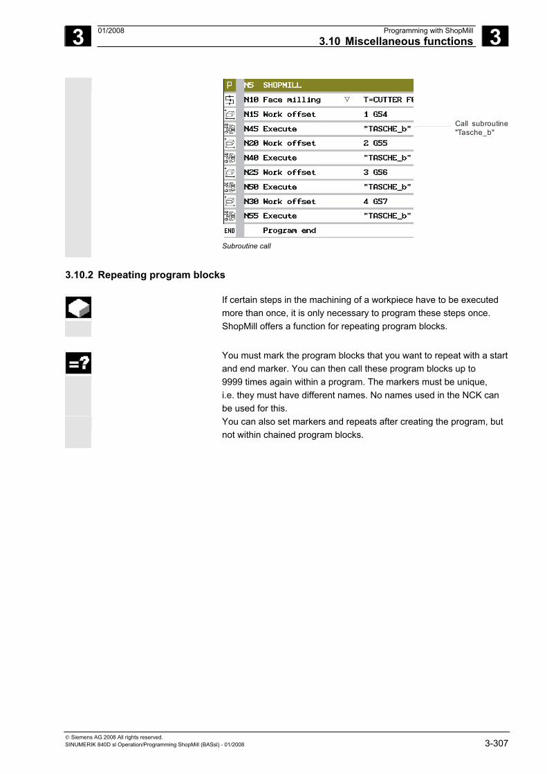
3 01/2008 Programming with ShopMill3.10 Miscellaneous functions
3
© Siemens AG 2008 All rights reserved. SINUMERIK 840D sl Operation/Programming ShopMill (BASsl) - 01/2008 3-307
Call subroutine"Tasche_b"
Subroutine call
3.10.2 Repeating program blocks
If certain steps in the machining of a workpiece have to be executed more than once, it is only necessary to program these steps once. ShopMill offers a function for repeating program blocks.
You must mark the program blocks that you want to repeat with a start
and end marker. You can then call these program blocks up to 9999 times again within a program. The markers must be unique, i.e. they must have different names. No names used in the NCK can be used for this.
You can also set markers and repeats after creating the program, but not within chained program blocks.
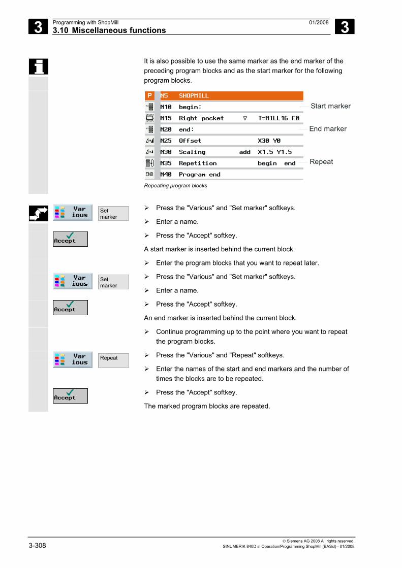
3 Programming with ShopMill 01/2008 3.10 Miscellaneous functions
3
© Siemens AG 2008 All rights reserved. 3-308 SINUMERIK 840D sl Operation/Programming ShopMill (BASsl) - 01/2008
It is also possible to use the same marker as the end marker of the preceding program blocks and as the start marker for the following program blocks.
Start marker
End marker
Repeat
Repeating program blocks
Setmarker
Press the "Various" and "Set marker" softkeys.
Enter a name.
Press the "Accept" softkey.
A start marker is inserted behind the current block.
Enter the program blocks that you want to repeat later.
Setmarker
Press the "Various" and "Set marker" softkeys.
Enter a name.
Press the "Accept" softkey.
An end marker is inserted behind the current block.
Continue programming up to the point where you want to repeat the program blocks.
Repeat
Press the "Various" and "Repeat" softkeys.
Enter the names of the start and end markers and the number of times the blocks are to be repeated.
Press the "Accept" softkey.
The marked program blocks are repeated.
3 01/2008 Programming with ShopMill3.10 Miscellaneous functions
3
© Siemens AG 2008 All rights reserved. SINUMERIK 840D sl Operation/Programming ShopMill (BASsl) - 01/2008 3-309
3.10.3 Changing program settings
All parameters defined in the program header, with the exception of the unit of measurement, can be changed at any location in the program.
The settings in the program header are modal, i.e. they remain active
until they are changed.
Define a new blank, e.g. in the sequential control program, if you want to change the visible cutout during simulation.
This is useful for the work offset, coordinate transformation, cylinder
peripheral surface transformation and swiveling functions. First program the functions listed above and then define a new blank.
Settings >
Press the "Various" and "Settings" softkeys.
Enter the desired parameters. For a description of the parameters, see Section "Creating a new program".
Press the "Accept" softkey.
The new settings for the program are loaded.
3.10.4 Calling zero offsets
You can call work offsets (G54, etc.) from any program. You can use these offsets, for example, when you want to machine workpieces with various blank dimensions using the same program. The offset will, in this case, adapt the workpiece zero to the new blank.
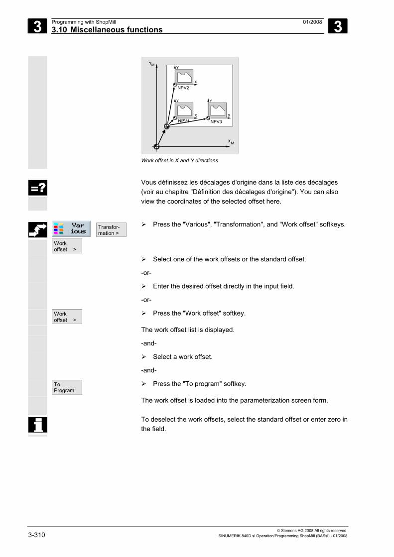
3 Programming with ShopMill 01/2008 3.10 Miscellaneous functions
3
© Siemens AG 2008 All rights reserved. 3-310 SINUMERIK 840D sl Operation/Programming ShopMill (BASsl) - 01/2008
Y
X
Y
X
Y
X
Y
XNPV1
NPV2
NPV3
M
M
Work offset in X and Y directions
Vous définissez les décalages d'origine dans la liste des décalages
(voir au chapitre "Définition des décalages d'origine"). You can also view the coordinates of the selected offset here.
Transfor- mation >
Workoffset >
Press the "Various", "Transformation", and "Work offset" softkeys.
Select one of the work offsets or the standard offset.
-or-
Enter the desired offset directly in the input field.
-or-
Workoffset >
Press the "Work offset" softkey.
The work offset list is displayed.
-and-
Select a work offset.
-and-
To Program
Press the "To program" softkey.
The work offset is loaded into the parameterization screen form.
To deselect the work offsets, select the standard offset or enter zero inthe field.
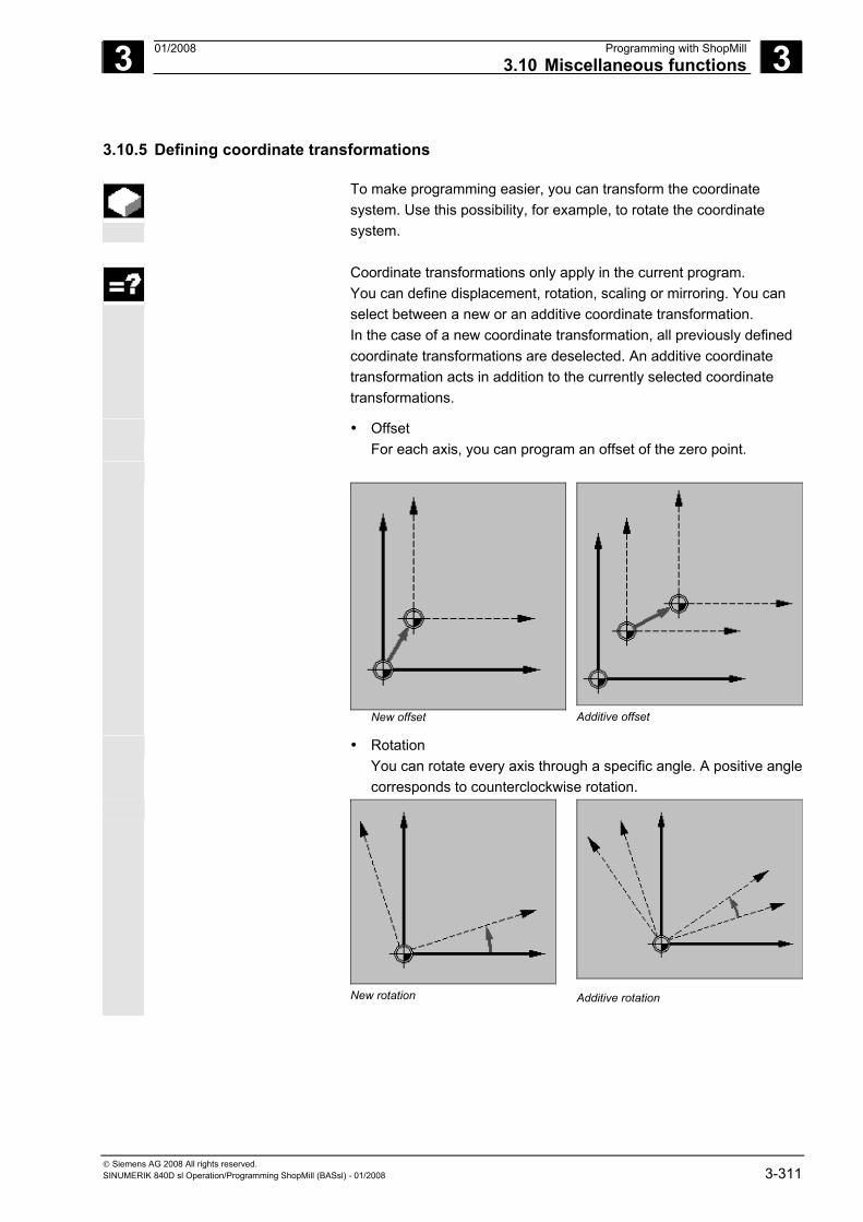
3 01/2008 Programming with ShopMill3.10 Miscellaneous functions
3
© Siemens AG 2008 All rights reserved. SINUMERIK 840D sl Operation/Programming ShopMill (BASsl) - 01/2008 3-311
3.10.5 Defining coordinate transformations
To make programming easier, you can transform the coordinate system. Use this possibility, for example, to rotate the coordinate system.
Coordinate transformations only apply in the current program.
You can define displacement, rotation, scaling or mirroring. You can select between a new or an additive coordinate transformation. In the case of a new coordinate transformation, all previously defined coordinate transformations are deselected. An additive coordinate transformation acts in addition to the currently selected coordinate transformations.
• Offset For each axis, you can program an offset of the zero point.
New offset
Additive offset
• Rotation You can rotate every axis through a specific angle. A positive angle corresponds to counterclockwise rotation.
New rotation
Additive rotation
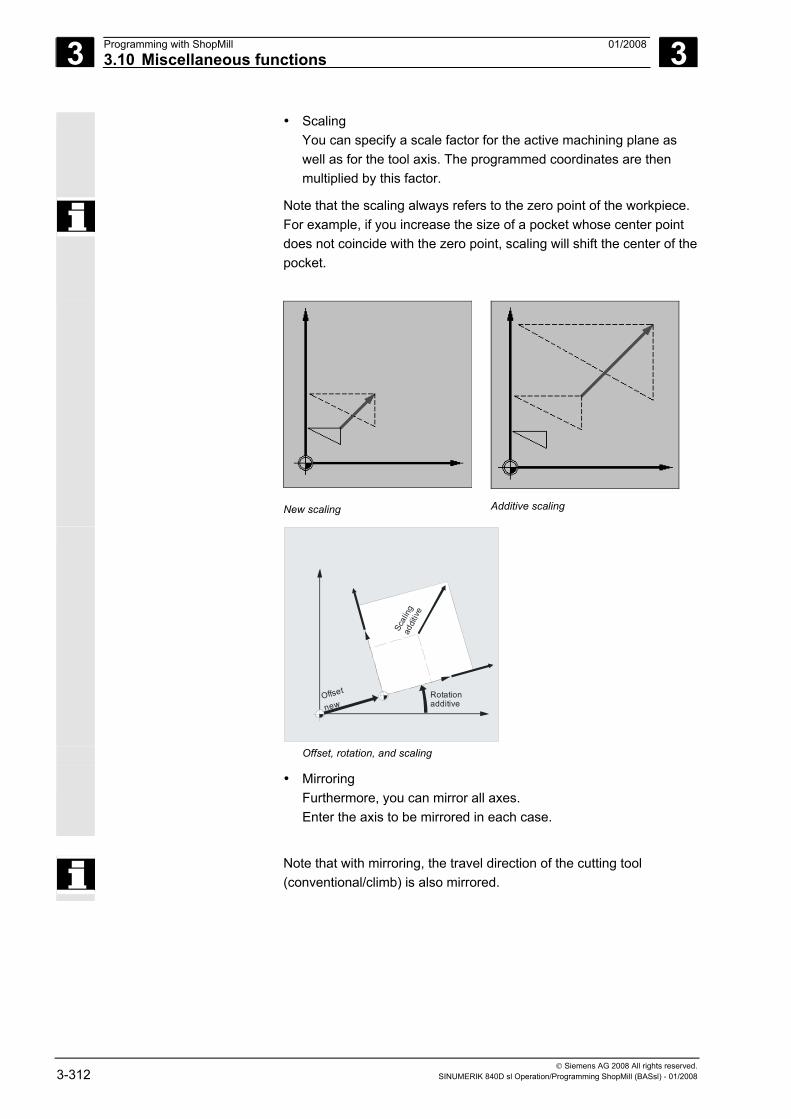
3 Programming with ShopMill 01/2008 3.10 Miscellaneous functions
3
© Siemens AG 2008 All rights reserved. 3-312 SINUMERIK 840D sl Operation/Programming ShopMill (BASsl) - 01/2008
• Scaling You can specify a scale factor for the active machining plane as well as for the tool axis. The programmed coordinates are then multiplied by this factor.
Note that the scaling always refers to the zero point of the workpiece. For example, if you increase the size of a pocket whose center point does not coincide with the zero point, scaling will shift the center of the pocket.
New scaling
Additive scaling
Offset
new
Sca l
ing
Rotationadditive
addit
ive
Offset, rotation, and scaling
• Mirroring Furthermore, you can mirror all axes. Enter the axis to be mirrored in each case.
Note that with mirroring, the travel direction of the cutting tool
(conventional/climb) is also mirrored.
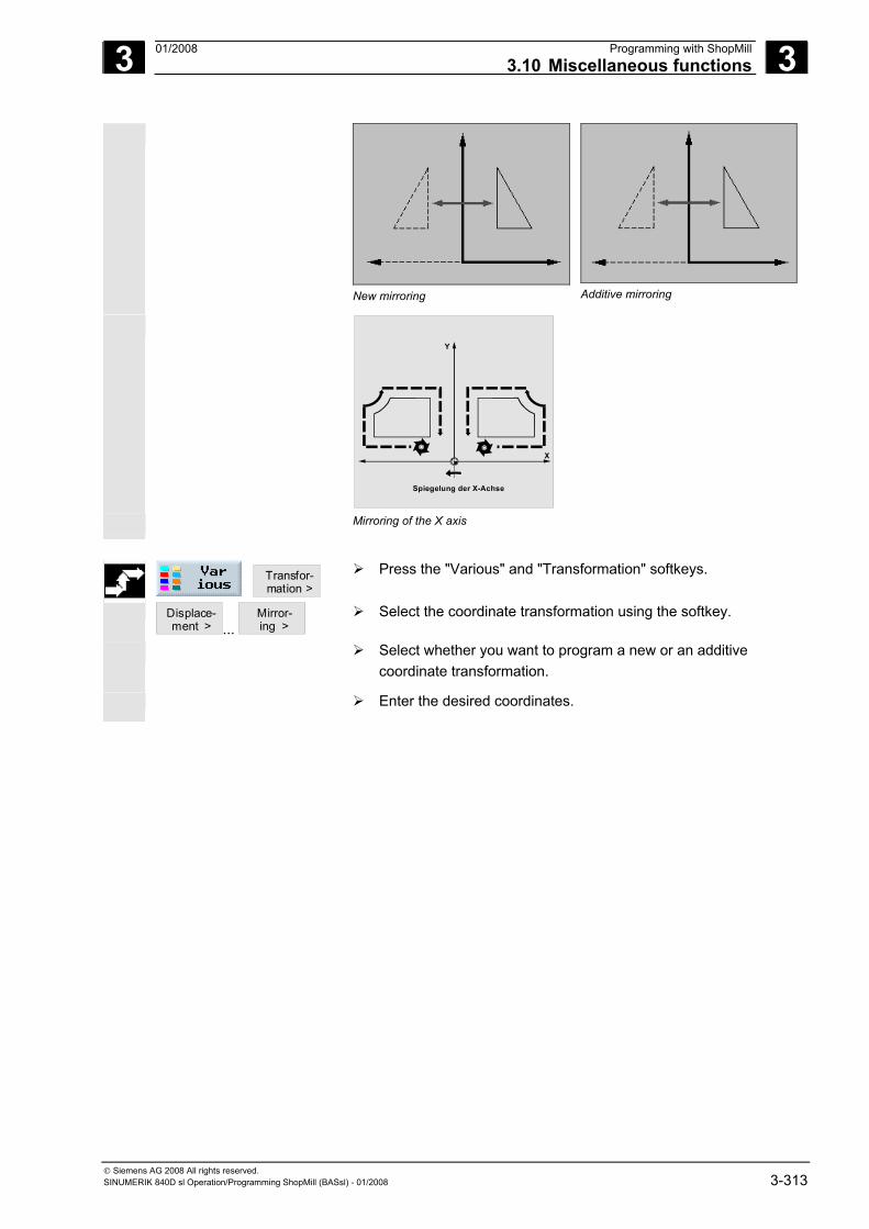
3 01/2008 Programming with ShopMill3.10 Miscellaneous functions
3
© Siemens AG 2008 All rights reserved. SINUMERIK 840D sl Operation/Programming ShopMill (BASsl) - 01/2008 3-313
New mirroring
Additive mirroring
X
Y
Spiegelung der X-Achse
Mirroring of the X axis
Transfor- mation >
Press the "Various" and "Transformation" softkeys.
Displace- ment > ...
Mirror- ing >
Select the coordinate transformation using the softkey.
Select whether you want to program a new or an additive coordinate transformation.
Enter the desired coordinates.
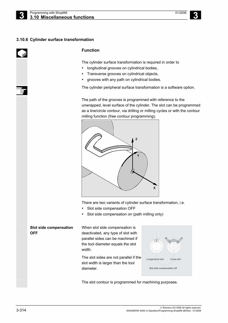
3 Programming with ShopMill 01/2008 3.10 Miscellaneous functions
3
© Siemens AG 2008 All rights reserved. 3-314 SINUMERIK 840D sl Operation/Programming ShopMill (BASsl) - 01/2008
3.10.6 Cylinder surface transformation
Function
The cylinder surface transformation is required in order to • longitudinal grooves on cylindrical bodies, • Transverse grooves on cylindrical objects, • grooves with any path on cylindrical bodies.
The cylinder peripheral surface transformation is a software option.
The path of the grooves is programmed with reference to the unwrapped, level surface of the cylinder. The slot can be programmed as a line/circle contour, via drilling or milling cycles or with the contour milling function (free contour programming).
X
Z
Y
There are two variants of cylinder surface transformation, i.e. • Slot side compensation OFF • Slot side compensation on (path milling only)
Slot side compensation
OFF When slot side compensation is deactivated, any type of slot with parallel sides can be machined if the tool diameter equals the slot width.
The slot sides are not parallel if the slot width is larger than the tool diameter.
Longitudinal slot Cross slot
Slot side compensation off
The slot contour is programmed for machining purposes.
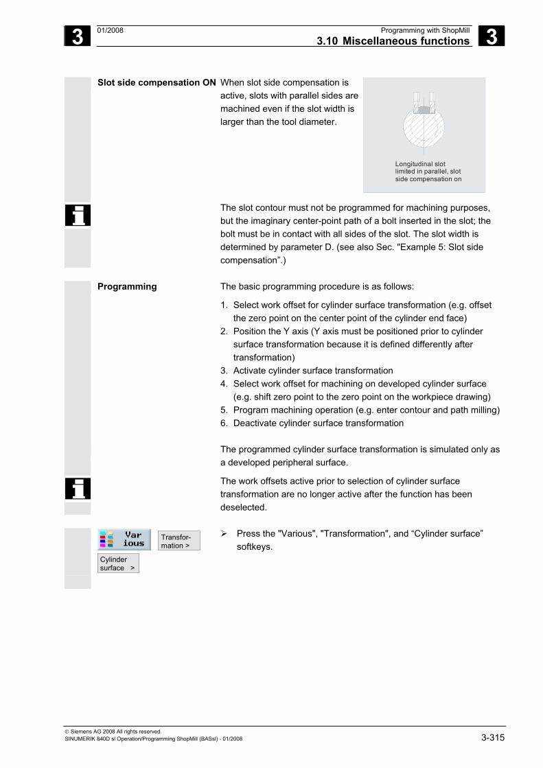
3 01/2008 Programming with ShopMill3.10 Miscellaneous functions
3
© Siemens AG 2008 All rights reserved. SINUMERIK 840D sl Operation/Programming ShopMill (BASsl) - 01/2008 3-315
Slot side compensation ON When slot side compensation is active, slots with parallel sides are machined even if the slot width is larger than the tool diameter.
Longitudinal slot limited in parallel, slot side compensation on
The slot contour must not be programmed for machining purposes, but the imaginary center-point path of a bolt inserted in the slot; the bolt must be in contact with all sides of the slot. The slot width is determined by parameter D. (see also Sec. "Example 5: Slot side compensation”.)
Programming The basic programming procedure is as follows:
1. Select work offset for cylinder surface transformation (e.g. offset the zero point on the center point of the cylinder end face)
2. Position the Y axis (Y axis must be positioned prior to cylinder surface transformation because it is defined differently after transformation)
3. Activate cylinder surface transformation 4. Select work offset for machining on developed cylinder surface
(e.g. shift zero point to the zero point on the workpiece drawing) 5. Program machining operation (e.g. enter contour and path milling) 6. Deactivate cylinder surface transformation
The programmed cylinder surface transformation is simulated only as a developed peripheral surface.
The work offsets active prior to selection of cylinder surface transformation are no longer active after the function has been deselected.
Transfor- mation >
Cylindersurface >
Press the "Various", "Transformation", and “Cylinder surface” softkeys.
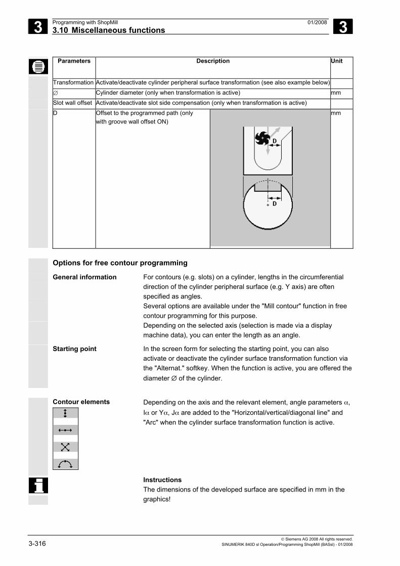
3 Programming with ShopMill 01/2008 3.10 Miscellaneous functions
3
© Siemens AG 2008 All rights reserved. 3-316 SINUMERIK 840D sl Operation/Programming ShopMill (BASsl) - 01/2008
Parameters Description Unit
Transformation Activate/deactivate cylinder peripheral surface transformation (see also example below)
∅ Cylinder diameter (only when transformation is active) mm
Slot wall offset Activate/deactivate slot side compensation (only when transformation is active)
D Offset to the programmed path (only with groove wall offset ON)
mm
Options for free contour programming
General information For contours (e.g. slots) on a cylinder, lengths in the circumferential direction of the cylinder peripheral surface (e.g. Y axis) are often specified as angles.
Several options are available under the "Mill contour" function in free contour programming for this purpose.
Depending on the selected axis (selection is made via a display machine data), you can enter the length as an angle.
Starting point In the screen form for selecting the starting point, you can also activate or deactivate the cylinder surface transformation function via the "Alternat." softkey. When the function is active, you are offered the diameter ∅ of the cylinder.
Contour elements
Depending on the axis and the relevant element, angle parameters α, Iα or Yα, Jα are added to the "Horizontal/vertical/diagonal line" and "Arc" when the cylinder surface transformation function is active.
Instructions The dimensions of the developed surface are specified in mm in the graphics!
3 01/2008 Programming with ShopMill3.10 Miscellaneous functions
3
© Siemens AG 2008 All rights reserved. SINUMERIK 840D sl Operation/Programming ShopMill (BASsl) - 01/2008 3-317
3.10.7 Swiveling
You can use swivel heads or swivel tables to create and/or machine inclined planes.
It is not necessary to program the swivel axes of the machine (A, B,
C), since you can specify the rotations around the geometry axes (X, Y, Z) of the workpiece coordinate system directly as described in the relevant workpiece drawing. The rotation of the workpiece coordinate system in the program is then automatically converted to a rotation of the relevant swivel axis of the machine during machining.
Alternatively, you can program the swivel axes of the machine directly and generate a matching coordinate system for those swivel axis positions. The generated coordinate system depends on the kinematics of your machine. A program generated with it can usually not be used on another machine without adaptation.
The swivel axes are always rotated to place the machining plane perpendicular to the tool axis for machining. During machining, the machining plane is permanently set.
When the coordinate system is swiveled, the previously set work offset is automatically converted for the swiveled state.
The main programming procedure is:
1. Swivel the coordinate system into the plane to be machined. 2. Program machining as usual in the X/Y plane. 3. Swivel the coordinate system back to its original position.
It is possible the software limit switches may be violated in the swiveled plane when approaching the programmed machining. In this case, ShopMill travels along the software limit switches above the retraction plane. In the event of violation below the retraction plane, the program is interrupted with an alarm for safety's sake. To avoid this, before swiveling, e.g. move the tool in the X/Y plane and position it as close as possible to the starting point of the machining operation or define the retraction plane closer to the workpiece.
In a swiveled plane the "Workpiece zero" function is operative but not the "Measure tool" function. The swiveled coordinates are retained in reset state and even after power ON, i.e. you can still retract from an inclined hole by retracting in +Z direction.
Please also refer to the machine manufacturer's instructions.
3 Programming with ShopMill 01/2008 3.10 Miscellaneous functions
3
© Siemens AG 2008 All rights reserved. 3-318 SINUMERIK 840D sl Operation/Programming ShopMill (BASsl) - 01/2008
The following provides an explanation of the most important parameters for swiveling:
Retract Before swiveling the axes you can move the tool to a safe retraction position. The retraction methods available to you are defined in the "Retraction position" parameter during set-up of the swivel data set. The retraction mode is modal. On a tool change or after a block search, the retraction mode last set is used.
Please also refer to the machine manufacturer's instructions.
Warning
You must select a retraction position that precludes collision between the tool and workpiece during swiveling.
Swiveling Select whether to rotate the coordinate system, for example, to execute a further swivel in the new coordinate system or whether to really traverse the swivel axes. If you want to perform a machining operation in the swiveled plane, you will need to be able to move the swivel axes.
Swivel method The coordinate system can be swiveled either axially, via projection angles or directly. The machine manufacturer determines when settingup the "Swivel" function which swivel methods are available.
Please also refer to the machine manufacturer's instructions.
• In the case of axial swiveling, the coordinate system is rotated about each axis in turn, with each rotation starting from the previous rotation. The axis sequence can be freely selected.
• With the solid angle swiveling option, the tool is first rotated about the Z axis and then about the Y axis. The second rotation starts from the first.
• When swiveling via projection angle, rotation is carried out about two axes simultaneously, i.e. you can view two angles at the same time. The third rotation is based on the first two. You can select any of the axes. This method is used, for example, for oblique drilling with angles dimensioned in the side elevations of the part drawing. The side elevations then correspond to the unrotated coordinate system.
• In direct swiveling, the positions of the rotary axes are specified. ShopMill calculates a suitable new coordinate system based on those values. The tool axis is aligned in the Z direction. You can derive the resulting direction of the X and Y axis by traversing the axes. By rotating the coordinate system around the Z axis, you can adapt the direction.
The positive direction of each rotation for the different swivel options is shown in the help displays.
3 01/2008 Programming with ShopMill3.10 Miscellaneous functions
3
© Siemens AG 2008 All rights reserved. SINUMERIK 840D sl Operation/Programming ShopMill (BASsl) - 01/2008 3-319
Direction In swivel systems with 2 rotary axes, a particular plane can be reached in two different ways. You can choose between these two different positions in the "Direction" parameter. The +/- corresponds to the larger or smaller value of a rotary axis. This may affect the working area. When the swivel data set is set up, the entries in the "Direction" parameter determine for which rotary axis you can select each of the two settings.
Please also refer to the machine manufacturer's instructions.
If one of the two positions cannot be reached for mechanical reasons, the alternative position is automatically selected irrespective of the setting of the "Direction" parameter.
Fixing the tool tip To avoid collisions, you can use the 5-axis transformation (software option) to retain the position of the tool tip during swiveling. This function must be enabled in the "Follow-up tool" parameter when the "Swivel" function is set up.
Please also refer to the machine manufacturer's instructions.
Transfor- mation >
Swivel >
Press the "Various" and "Transformation" softkeys.
Initial setting
Press the "Initial setting" softkey to restore the initial state, i.e. to zero the values. This is done, for example, to swivel the coordinate system back to its original orientation.
Parameters Description Unit
TC Name of the swivel data block 0: Removing the swivel head, deselecting the swivel data set No entry: No change to set swivel data block
T Tool name
Retract No: Do not retract tool before swiveling Z: Move tool axis to retraction position before swiveling Z, X, Y: Move machining axis to retraction position before swiveling Tool max: Retract tool as far as the software limit switch in the tool direction Tool inc: Retract tool up to the incremental value entered in the tool direction
Swiveling Yes: compute and swivel (swivel coordinate system and move swivel axes) No: only compute, don't swivel (only swivel coordinate system, don't move swivel axes)
Transformation Swiveling additive or new
X0 Reference point for rotation mm
Y0 Reference point for rotation mm
Z0 Reference point for rotation mm
3 Programming with ShopMill 01/2008 3.10 Miscellaneous functions
3
© Siemens AG 2008 All rights reserved. 3-320 SINUMERIK 840D sl Operation/Programming ShopMill (BASsl) - 01/2008
Swivel method Axial: Swivel coordinate system axially Solid angle: Swivel via solid angle Projection angle: Swiveling via projection angle Direct: Position rotary axes directly
X Axis angle (axial swivel) The sequence of the axes Degrees Y Axis angle (axial swivel) can be replaced as required Degrees Z Axis angle (axial swivel) with "Alternat." Degrees α Angle of rotation in the XY plane about the Z axis (swiveling via solid angle) Degrees β Angle of rotation in space about the Y axis (swiveling via solid angle) Degrees Xα Axis angle (swiveling via projection angle) The sequence of the axes Degrees Yα Axis angle (swiveling via projection angle) can be replaced as required Degrees Zβ Axis angle (swiveling via projection angle) with "Alternat." Degrees B Rotary axis angle 1 (swivel directly) Degrees C Rotary axis angle 2 (swivel directly) Degrees WZ Rotating the coordinate system around the tool axis (swivel directly) Degrees X1 New zero point of rotated surface mm Y1 New zero point of rotated surface mm
Z1 New zero point of rotated surface mm
Direction Preferred direction of rotation with 2 alternatives +: Larger angle of the axis on the scale of the swivel head / swivel table -: Smaller angle of the axis on the scale of the swivel head / swivel table
Fix tool tip Follow-up: The position of the tool tip is maintained during swiveling. Do not correct: The position of the tool tip is changes during swiveling.
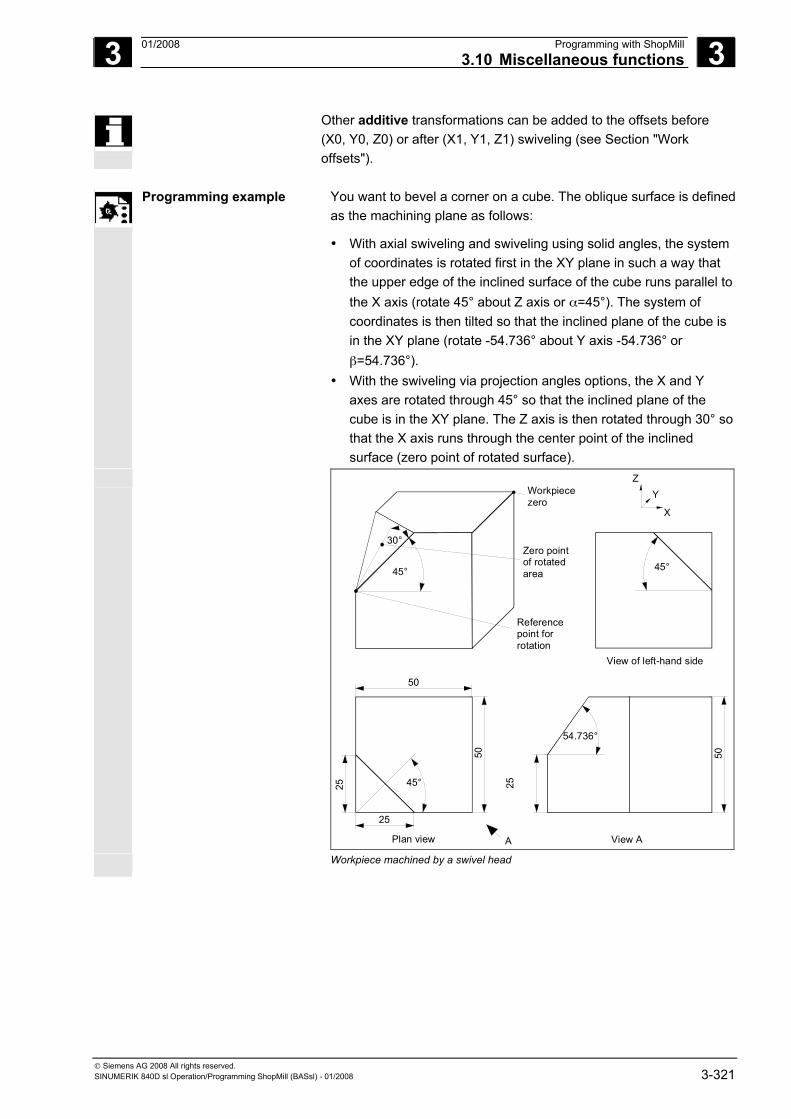
3 01/2008 Programming with ShopMill3.10 Miscellaneous functions
3
© Siemens AG 2008 All rights reserved. SINUMERIK 840D sl Operation/Programming ShopMill (BASsl) - 01/2008 3-321
Other additive transformations can be added to the offsets before (X0, Y0, Z0) or after (X1, Y1, Z1) swiveling (see Section "Work offsets").
Programming example You want to bevel a corner on a cube. The oblique surface is defined
as the machining plane as follows:
• With axial swiveling and swiveling using solid angles, the system of coordinates is rotated first in the XY plane in such a way that the upper edge of the inclined surface of the cube runs parallel to the X axis (rotate 45° about Z axis or α=45°). The system of coordinates is then tilted so that the inclined plane of the cube is in the XY plane (rotate -54.736° about Y axis -54.736° or β=54.736°).
• With the swiveling via projection angles options, the X and Y axes are rotated through 45° so that the inclined plane of the cube is in the XY plane. The Z axis is then rotated through 30° so that the X axis runs through the center point of the inclined surface (zero point of rotated surface).
Workpiecezero
Zero pointof rotatedarea
Referencepoint forrotation
54.736°
View A
50
50
25
APlan view
50
25 2545°
Z
X
Y
45°
30°
45°
View of left-hand side
Workpiece machined by a swivel head
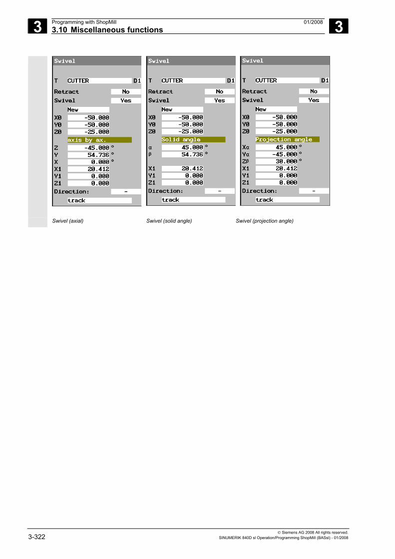
3 Programming with ShopMill 01/2008 3.10 Miscellaneous functions
3
© Siemens AG 2008 All rights reserved. 3-322 SINUMERIK 840D sl Operation/Programming ShopMill (BASsl) - 01/2008
Swivel (axial) Swivel (solid angle) Swivel (projection angle)
3 01/2008 Programming with ShopMill3.10 Miscellaneous functions
3
© Siemens AG 2008 All rights reserved. SINUMERIK 840D sl Operation/Programming ShopMill (BASsl) - 01/2008 3-323
3.10.8 Miscellaneous functions
You can e.g. position the spindle again between the individual machining steps or activate the coolant or stop machining.
The following functions are available:
• Spindle Determine direction of spindle rotation or spindle position (see Section "Starting, stopping, and positioning a spindle manually")
• Gear stage Set gear stage, if machine has gears
Please also refer to the machine manufacturer's instructions.
• Miscellaneous M functions Machine functions, such as "Close door"; they are additionally provided by the machine manufacturer
Please also refer to the machine manufacturer's instructions.
• Coolant Activate/deactivate coolant 1/2
• Tool-spec. fct 1 to 4 Select tool-specific functions 1 to 4; they are additionally provided by the machine manufacturer
Please also refer to the machine manufacturer's instructions.
• Dwell time Set time after which execution on the machine is continued
• Programmed stop Stop execution on the machine if the "Programmed stop softkey is also active (see Sec. "Program control")
• Stop Stop execution on the machine
Machine funct. >
Press the "Strai. Circle" and "Machine funct." softkeys.
Enter the desired parameters.
Press the "Accept" softkey.
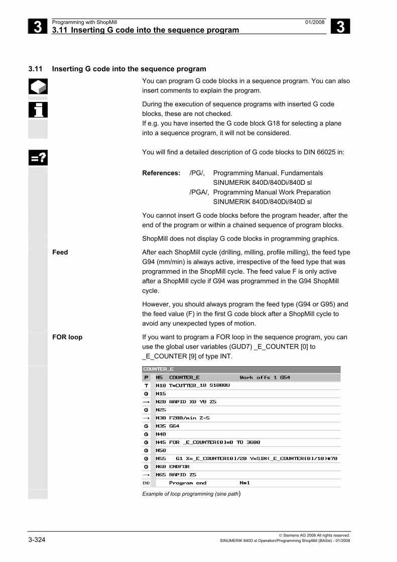
3 Programming with ShopMill 01/2008 3.11 Inserting G code into the sequence program
3
© Siemens AG 2008 All rights reserved. 3-324 SINUMERIK 840D sl Operation/Programming ShopMill (BASsl) - 01/2008
3.11 Inserting G code into the sequence program You can program G code blocks in a sequence program. You can also
insert comments to explain the program.
During the execution of sequence programs with inserted G code blocks, these are not checked. If e.g. you have inserted the G code block G18 for selecting a plane into a sequence program, it will not be considered.
You will find a detailed description of G code blocks to DIN 66025 in:
References: /PG/, Programming Manual, Fundamentals SINUMERIK 840D/840Di/840D sl /PGA/, Programming Manual Work Preparation SINUMERIK 840D/840Di/840D sl
You cannot insert G code blocks before the program header, after the end of the program or within a chained sequence of program blocks.
ShopMill does not display G code blocks in programming graphics.
Feed After each ShopMill cycle (drilling, milling, profile milling), the feed type G94 (mm/min) is always active, irrespective of the feed type that was programmed in the ShopMill cycle. The feed value F is only active after a ShopMill cycle if G94 was programmed in the G94 ShopMill cycle.
However, you should always program the feed type (G94 or G95) and the feed value (F) in the first G code block after a ShopMill cycle to avoid any unexpected types of motion.
FOR loop
If you want to program a FOR loop in the sequence program, you can use the global user variables (GUD7) _E_COUNTER [0] to _E_COUNTER [9] of type INT.
Example of loop programming (sine path)
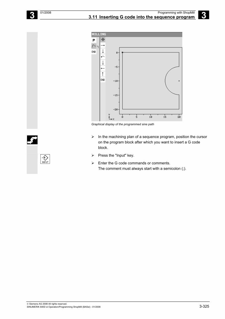
3 01/2008 Programming with ShopMill3.11 Inserting G code into the sequence program
3
© Siemens AG 2008 All rights reserved. SINUMERIK 840D sl Operation/Programming ShopMill (BASsl) - 01/2008 3-325
Graphical display of the programmed sine path
In the machining plan of a sequence program, position the cursor
on the program block after which you want to insert a G code block.
Press the "Input" key.
Enter the G code commands or comments. The comment must always start with a semicolon (;).
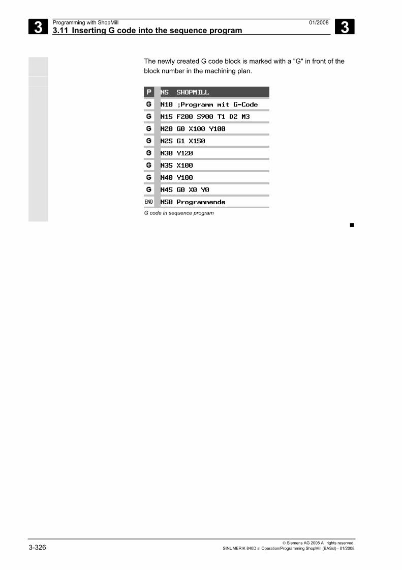
3 Programming with ShopMill 01/2008 3.11 Inserting G code into the sequence program
3
© Siemens AG 2008 All rights reserved. 3-326 SINUMERIK 840D sl Operation/Programming ShopMill (BASsl) - 01/2008
The newly created G code block is marked with a "G" in front of the block number in the machining plan.
G code in sequence program
4 01/2008 Programming with G Code 4
© Siemens AG 2008 All rights reserved. SINUMERIK 840D sl Operation/Programming ShopMill (BASsl) - 01/2008 4-327
Programming with G Code 4.1 Creating a G code program .................................................................................... 4-328
4.2 Executing a G code program .................................................................................. 4-331
4.3 G code editor........................................................................................................... 4-333
4.4 Arithmetic variables................................................................................................. 4-337
4.5 ISO dialects............................................................................................................. 4-338
4 Programming with G Code 01/2008 4.1 Creating a G code program
4
© Siemens AG 2008 All rights reserved. 4-328 SINUMERIK 840D sl Operation/Programming ShopMill (BASsl) - 01/2008
4.1 Creating a G code program If you do not want to program with the ShopMill functions, you can
also generate a G code program with G code commands in the ShopMill user interface.
You can program a G code command according to DIN 66025.
In addition, the parameter screens offer support for measuring and programming contours, drilling and milling cycles. G code is generated from the individual forms, which you can recompile back to the screen forms. The measuring cycle support function must be set up by the machine manufacturer.
Please also refer to the machine manufacturer's instructions.
For a detailed description of G code commands to DIN 66025, and of cycles and measuring cycles, please refer to: References: /PG/, Programming Manual, Fundamentals SINUMERIK 840D/840Di/840D sl /PGA/, Programming Manual Work Preparation SINUMERIK 840D/840Di/840D sl /PGZ/, Programming Manual Cycles SINUMERIK 840D/840Di/840D sl /BNM/, Programming Manual Measuring Cycles SINUMERIK 840D/840Di/840D sl
You can call up context-sensitive help, if you require more information on particular G code commands or cycle parameters on the PCU 50.3 (HMI Advanced).
For a detailed description of the online help, please refer to: References: /BAD/, Operating Manual HMI-Advanced SINUMERIK 840D/840Di/840D sl
Creating a G code
program
Press the "Program" softkey.
Select the directory in which you want to create a new program.
New
G codeprogram
Press the "New" and "G code program" softkeys.
Enter a program name. Program names may be a maximum of 24 characters in length. You can use any letters (except umlauts), digits or the underscore symbol (_). ShopMill automatically replaces lower case with upper case.
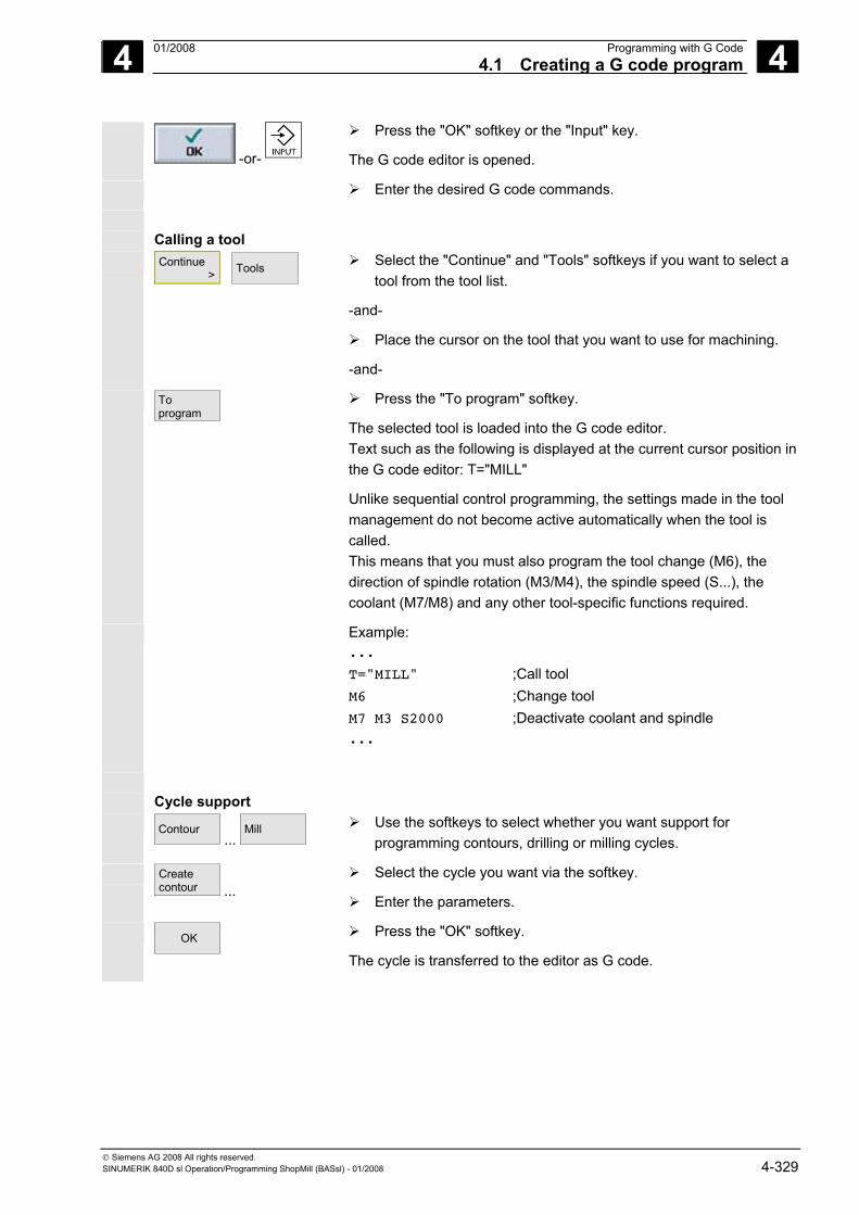
4 01/2008 Programming with G Code4.1 Creating a G code program
4
© Siemens AG 2008 All rights reserved. SINUMERIK 840D sl Operation/Programming ShopMill (BASsl) - 01/2008 4-329
-or-
Press the "OK" softkey or the "Input" key.
The G code editor is opened.
Enter the desired G code commands.
Calling a tool Continue
> Tools
Select the "Continue" and "Tools" softkeys if you want to select a
tool from the tool list.
-and-
Place the cursor on the tool that you want to use for machining.
-and-
Toprogram
Press the "To program" softkey.
The selected tool is loaded into the G code editor. Text such as the following is displayed at the current cursor position in the G code editor: T="MILL"
Unlike sequential control programming, the settings made in the tool management do not become active automatically when the tool is called. This means that you must also program the tool change (M6), the direction of spindle rotation (M3/M4), the spindle speed (S...), the coolant (M7/M8) and any other tool-specific functions required.
Example: ...
T="MILL" ;Call tool M6 ;Change tool M7 M3 S2000 ;Deactivate coolant and spindle ...
Cycle support Contour
... Mill
Use the softkeys to select whether you want support for
programming contours, drilling or milling cycles.
Createcontour ...
Select the cycle you want via the softkey.
Enter the parameters.
OK
Press the "OK" softkey.
The cycle is transferred to the editor as G code.
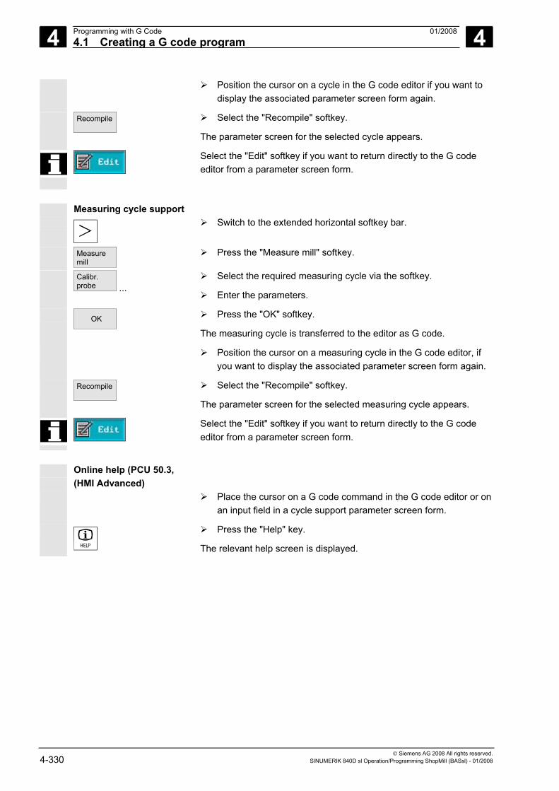
4 Programming with G Code 01/2008 4.1 Creating a G code program
4
© Siemens AG 2008 All rights reserved. 4-330 SINUMERIK 840D sl Operation/Programming ShopMill (BASsl) - 01/2008
Position the cursor on a cycle in the G code editor if you want to display the associated parameter screen form again.
Recompile
Select the "Recompile" softkey.
The parameter screen for the selected cycle appears.
Select the "Edit" softkey if you want to return directly to the G code editor from a parameter screen form.
Measuring cycle support
Switch to the extended horizontal softkey bar.
Measuremill
Press the "Measure mill" softkey.
Calibr.probe ...
Select the required measuring cycle via the softkey.
Enter the parameters.
OK
Press the "OK" softkey.
The measuring cycle is transferred to the editor as G code.
Position the cursor on a measuring cycle in the G code editor, if you want to display the associated parameter screen form again.
Recompile
Select the "Recompile" softkey.
The parameter screen for the selected measuring cycle appears.
Select the "Edit" softkey if you want to return directly to the G code editor from a parameter screen form.
Online help (PCU 50.3,
(HMI Advanced)
Place the cursor on a G code command in the G code editor or on an input field in a cycle support parameter screen form.
Press the "Help" key.
The relevant help screen is displayed.
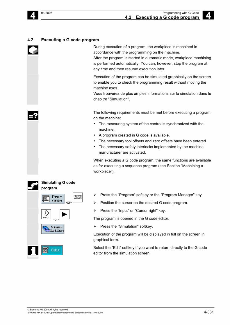
4 01/2008 Programming with G Code4.2 Executing a G code program
4
© Siemens AG 2008 All rights reserved. SINUMERIK 840D sl Operation/Programming ShopMill (BASsl) - 01/2008 4-331
4.2 Executing a G code program During execution of a program, the workpiece is machined in
accordance with the programming on the machine. After the program is started in automatic mode, workpiece machining is performed automatically. You can, however, stop the program at any time and then resume execution later.
Execution of the program can be simulated graphically on the screen to enable you to check the programming result without moving the machine axes. Vous trouverez de plus amples informations sur la simulation dans le chapitre "Simulation".
The following requirements must be met before executing a program
on the machine: • The measuring system of the control is synchronized with the
machine. • A program created in G code is available. • The necessary tool offsets and zero offsets have been entered. • The necessary safety interlocks implemented by the machine
manufacturer are activated.
When executing a G code program, the same functions are available as for executing a sequence program (see Section "Machining a workpiece").
Simulating G code
program
-or-
Press the "Program" softkey or the "Program Manager" key.
Position the cursor on the desired G code program.
-or-
Press the "Input" or "Cursor right" key.
The program is opened in the G code editor.
Press the "Simulation" softkey.
Execution of the program will be displayed in full on the screen in graphical form.
Select the "Edit" softkey if you want to return directly to the G code editor from the simulation screen.
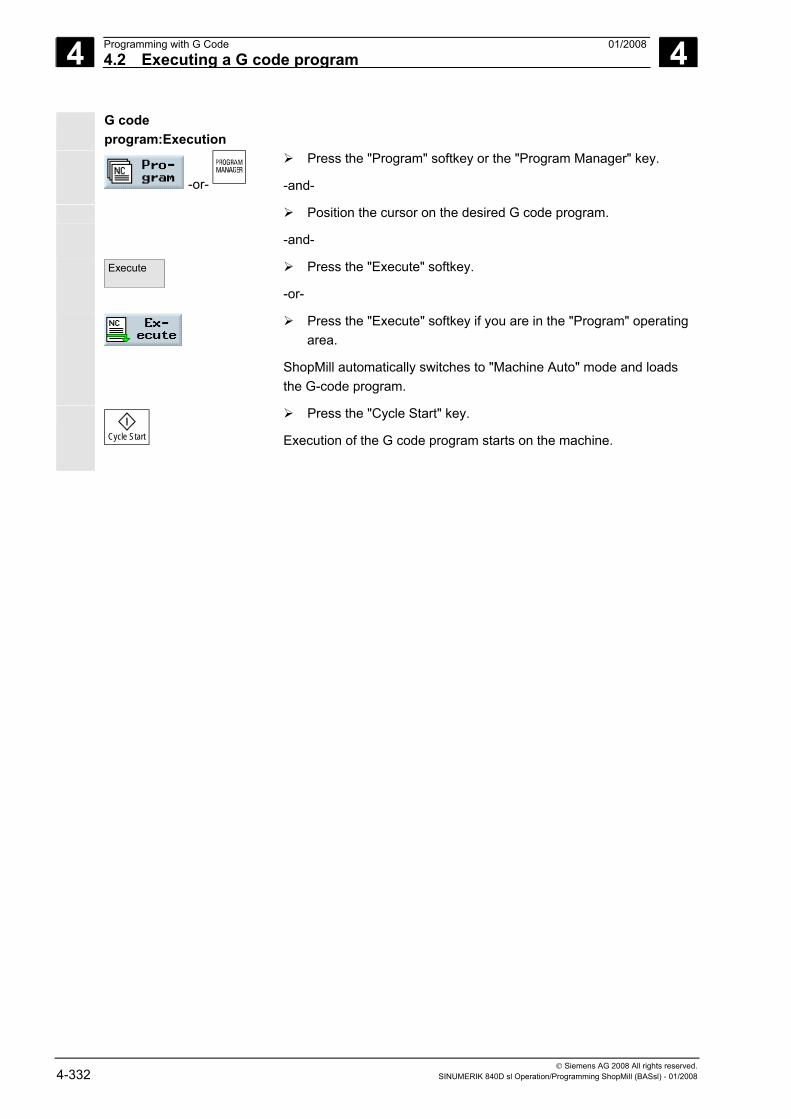
4 Programming with G Code 01/2008 4.2 Executing a G code program
4
© Siemens AG 2008 All rights reserved. 4-332 SINUMERIK 840D sl Operation/Programming ShopMill (BASsl) - 01/2008
G code program:Execution
-or-
Press the "Program" softkey or the "Program Manager" key.
-and-
Position the cursor on the desired G code program.
-and-
Execute
Press the "Execute" softkey.
-or-
Press the "Execute" softkey if you are in the "Program" operating area.
ShopMill automatically switches to "Machine Auto" mode and loads the G-code program.
Cycle Start
Press the "Cycle Start" key.
Execution of the G code program starts on the machine.
4 01/2008 Programming with G Code4.3 G code editor
4
© Siemens AG 2008 All rights reserved. SINUMERIK 840D sl Operation/Programming ShopMill (BASsl) - 01/2008 4-333
4.3 G code editor You use the G code editor when you want to change the sequence of
program blocks within a G code program, delete program blocks or copy program blocks from one program to another.
When you want to change G code in a program that you are currently
executing, you can only change the G code blocks that have not yet been executed. These blocks are highlighted.
The following functions are available in the G code editor: • Select
You can select any G code. • Copy/paste
You can copy and paste G code within a program or between different programs.
• Cut You can cut and therefore delete any G code. However, the G code remains in the buffer, so you can still paste it in somewhere else.
• Search/replace In a G code program, you can search for a specific character string and replace it with a different one.
• To start/end You can jump easily to the start or end of the G code program.
• Number If you insert a new or copied G code block between two existing G code blocks, ShopMill automatically assigns a new block number. This block number may be higher than the one in the following block. The "Renumber" function is used to renumber the G code blocks in ascending order.
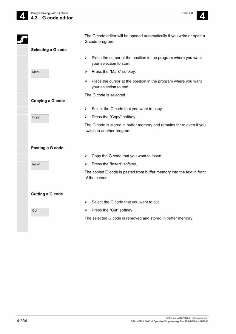
4 Programming with G Code 01/2008 4.3 G code editor
4
© Siemens AG 2008 All rights reserved. 4-334 SINUMERIK 840D sl Operation/Programming ShopMill (BASsl) - 01/2008
The G code editor will be opened automatically if you write or open a G code program.
Selecting a G code
Place the cursor at the position in the program where you want your selection to start.
Mark
Press the "Mark" softkey.
Place the cursor at the position in the program where you want your selection to end.
The G code is selected. Copying a G code
Select the G code that you want to copy.
Copy
Press the "Copy" softkey.
The G code is stored in buffer memory and remains there even if you switch to another program.
Pasting a G code
Copy the G code that you want to insert.
Insert
Press the "Insert" softkey.
The copied G code is pasted from buffer memory into the text in front of the cursor.
Cutting a G code
Select the G code that you want to cut.
Cut
Press the "Cut" softkey.
The selected G code is removed and stored in buffer memory.
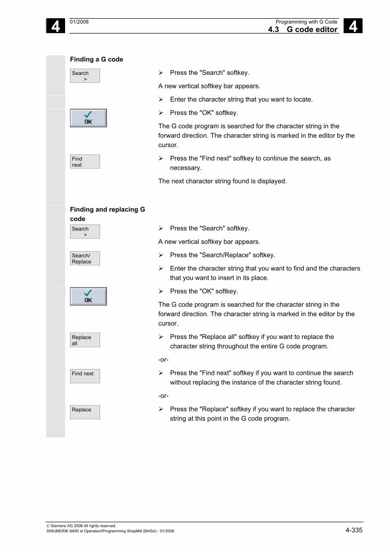
4 01/2008 Programming with G Code4.3 G code editor
4
© Siemens AG 2008 All rights reserved. SINUMERIK 840D sl Operation/Programming ShopMill (BASsl) - 01/2008 4-335
Finding a G code
Search >
Press the "Search" softkey.
A new vertical softkey bar appears.
Enter the character string that you want to locate.
Press the "OK" softkey.
The G code program is searched for the character string in the forward direction. The character string is marked in the editor by the cursor.
Find next
Press the "Find next" softkey to continue the search, as necessary.
The next character string found is displayed.
Finding and replacing G code
Search >
Press the "Search" softkey.
A new vertical softkey bar appears.
Search/Replace
Press the "Search/Replace" softkey.
Enter the character string that you want to find and the characters that you want to insert in its place.
Press the "OK" softkey.
The G code program is searched for the character string in the forward direction. The character string is marked in the editor by the cursor.
Replaceall
Press the "Replace all" softkey if you want to replace the character string throughout the entire G code program.
-or-
Find next
Press the "Find next" softkey if you want to continue the search without replacing the instance of the character string found.
-or-
Replace
Press the "Replace" softkey if you want to replace the character string at this point in the G code program.
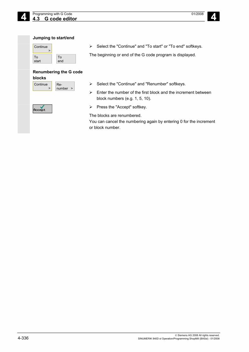
4 Programming with G Code 01/2008 4.3 G code editor
4
© Siemens AG 2008 All rights reserved. 4-336 SINUMERIK 840D sl Operation/Programming ShopMill (BASsl) - 01/2008
Jumping to start/end
Continue > Tostart
Toend
Select the "Continue" and "To start" or "To end" softkeys.
The beginning or end of the G code program is displayed.
Renumbering the G code blocks
Continue >
Re-number >
Select the "Continue" and "Renumber" softkeys.
Enter the number of the first block and the increment between block numbers (e.g. 1, 5, 10).
Press the "Accept" softkey.
The blocks are renumbered. You can cancel the numbering again by entering 0 for the increment or block number.
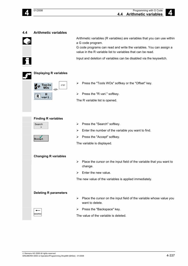
4 01/2008 Programming with G Code4.4 Arithmetic variables
4
© Siemens AG 2008 All rights reserved. SINUMERIK 840D sl Operation/Programming ShopMill (BASsl) - 01/2008 4-337
4.4 Arithmetic variables Arithmetic variables (R variables) are variables that you can use within
a G code program. G code programs can read and write the variables. You can assign a value in the R variable list to variables that can be read.
Input and deletion of variables can be disabled via the keyswitch.
Displaying R variables
-or-
Press the "Tools WOs" softkey or the "Offset" key.
Press the "R vari." softkey.
The R variable list is opened.
Finding R variables
Search >
Press the "Search" softkey.
Enter the number of the variable you want to find.
Press the "Accept" softkey.
The variable is displayed.
Changing R variables
Place the cursor on the input field of the variable that you want to change.
Enter the new value.
The new value of the variables is applied immediately.
Deleting R parameters
Place the cursor on the input field of the variable whose value you want to delete.
Press the "Backspace" key.
The value of the variable is deleted.
4 Programming with G Code 01/2008 4.5 ISO dialects
4
© Siemens AG 2008 All rights reserved. 4-338 SINUMERIK 840D sl Operation/Programming ShopMill (BASsl) - 01/2008
4.5 ISO dialects If ISO dialects are set up in ShopMill, you can also create and run ISO
dialect programs.
Please also refer to the machine manufacturer's instructions.
ISO dialect programs are not programs that were created with SIEMENS G code. See Section "Creating a G code program".
�

5 01/2008 Simulation 5
© Siemens AG 2008 All rights reserved. SINUMERIK 840D sl Operation/Programming ShopMill (BASsl) - 01/2008 5-339
Simulation 5.1 General information ................................................................................................ 5-340
5.2 Starting/stopping a program in standard simulation ............................................... 5-341
5.3 Plan view representation......................................................................................... 5-343
5.4 3-plane view representation.................................................................................... 5-344
5.5 Enlarging the viewport ............................................................................................ 5-345
5.6 Three-dimensional representation .......................................................................... 5-346 5.6.1 Changing the position of the viewport..................................................................... 5-347 5.6.2 Cutting the workpiece ............................................................................................. 5-348
5.7 Starting/stopping the quick display for mold making .............................................. 5-349
5.8 Quick display representations................................................................................. 5-349
5.9 Adjusting and moving the workpiece graphics........................................................ 5-351
5.10 Distance measurement ........................................................................................... 5-352
5.11 Search function ....................................................................................................... 5-353
5.12 Editing part program blocks .................................................................................... 5-354 5.12.1 Selecting G blocks .................................................................................................. 5-354 5.12.2 Editing a G code program....................................................................................... 5-355
5 Simulation 01/2008 5.1 General information
5
© Siemens AG 2008 All rights reserved. 5-340 SINUMERIK 840D sl Operation/Programming ShopMill (BASsl) - 01/2008
5.1 General information ShopMill provides various extensive and detailed simulation functions
for displaying machining paths.
Please also refer to the machine manufacturer's instructions. Standard simulation
During simulation, the current program is calculated in its entirety and the result displayed in graphic form.
You can select the following modes of representation for simulation:
• Top view • 3-plane view • Volume model
The simulation uses the correct proportions for the tools and workpiece contours. Cylindrical die-sinking cutters, bevel cutters, bevel cutters with corner rounding and tapered die-sinking cutters are displayed as end milling tools.
The traverse paths for the tools are shown in color: Red line = tool is moving at rapid traverse Green line = tool is moving at machining feedrate
In all views, a clock is displayed during graphical processing. The displayed machining time (in hours/minutes/seconds) indicates the approximate time that would actually be required to execute the machining program on the machine (incl. tool change). If a program is interrupted during simultaneous recording, the clock stops.
In addition, the current axis coordinates, the override, and the programblock currently being executed are also displayed. The active tool with the cutting edge number and feedrate are also displayed in the simulation.
Transformations Transformations are displayed differently during simulation and simultaneous recording: • Coordinate transformations (translation, scaling, …) are displayed
as programmed. • Cylinder surface transformations are displayed as a developed
surface. • After swivel transformation, the previous machining operations are
deleted from the display and only machining of the swiveled plane is displayed (viewing angle perpendicular to the swiveled plane).
• Zero offsets (G54, etc.) do not alter the zero in the graphical display. This means that, in the case of multiple clampings, the machining operations for each of the individual workpieces are plotted on top of one another.
5 01/2008 Simulation5.2 Starting/stopping a program in standard simulation
5
© Siemens AG 2008 All rights reserved. SINUMERIK 840D sl Operation/Programming ShopMill (BASsl) - 01/2008 5-341
If you want to display a different portion of the workpiece from the one defined in ShopMill, you can define a new blank in the program (see Section "Changing program settings").
Quick display for mold making
Quick display of traverse paths is possible for large part programs. In this quick dashed-line drawing view, all programmed positions (even those resulting from work offsets) are shown as axis paths resulting from G1.
Please also refer to the machine manufacturer's instructions. Quick display for mold making is only available for PCU 50.3 (HMI
Advanced).
5.2 Starting/stopping a program in standard simulation Start simulation
Requirements The required program • Sequence program or • G Code program has been selected and is in the program editor.
...
Standard
Press the "Simulation" and "Standard" softkeys.
Details
Single Block
Press the "Details" and "Single block" softkeys if you wish to process the program block by block.
Program processing will be graphically displayed on the screen. The machine axes do not move during this.
In the case of sequence programs, the dimensions of the blank for simulation are taken from the program header.
If a subroutine is called in the program, ShopMill evaluates the program header of the subroutine and uses the blank defined there for graphically displaying the part. The settings from the subroutine header remain effective, even after the subroutine has been executed.If you want to retain the blank used in the main program, delete the data relating to the blank in the subroutine header.
With G code programs, you must specify the dimensions of the blank or the selected viewport yourself.
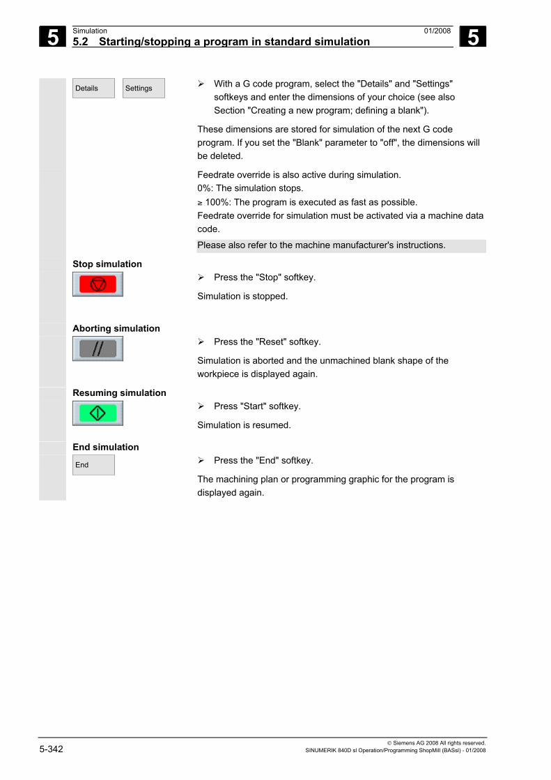
5 Simulation 01/2008 5.2 Starting/stopping a program in standard simulation
5
© Siemens AG 2008 All rights reserved. 5-342 SINUMERIK 840D sl Operation/Programming ShopMill (BASsl) - 01/2008
Details
Settings
With a G code program, select the "Details" and "Settings" softkeys and enter the dimensions of your choice (see also Section "Creating a new program; defining a blank").
These dimensions are stored for simulation of the next G code program. If you set the "Blank" parameter to "off", the dimensions will be deleted.
Feedrate override is also active during simulation. 0%: The simulation stops. ≥ 100%: The program is executed as fast as possible. Feedrate override for simulation must be activated via a machine data code.
Please also refer to the machine manufacturer's instructions.
Stop simulation
Press the "Stop" softkey.
Simulation is stopped.
Aborting simulation
Press the "Reset" softkey.
Simulation is aborted and the unmachined blank shape of the workpiece is displayed again.
Resuming simulation
Press "Start" softkey.
Simulation is resumed.
End simulation End
Press the "End" softkey.
The machining plan or programming graphic for the program is displayed again.
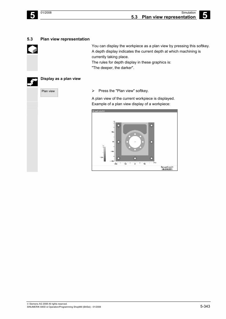
5 01/2008 Simulation5.3 Plan view representation
5
© Siemens AG 2008 All rights reserved. SINUMERIK 840D sl Operation/Programming ShopMill (BASsl) - 01/2008 5-343
5.3 Plan view representation You can display the workpiece as a plan view by pressing this softkey.
A depth display indicates the current depth at which machining is currently taking place. The rules for depth display in these graphics is: "The deeper, the darker".
Display as a plan view
Plan view
Press the "Plan view" softkey.
A plan view of the current workpiece is displayed. Example of a plan view display of a workpiece:
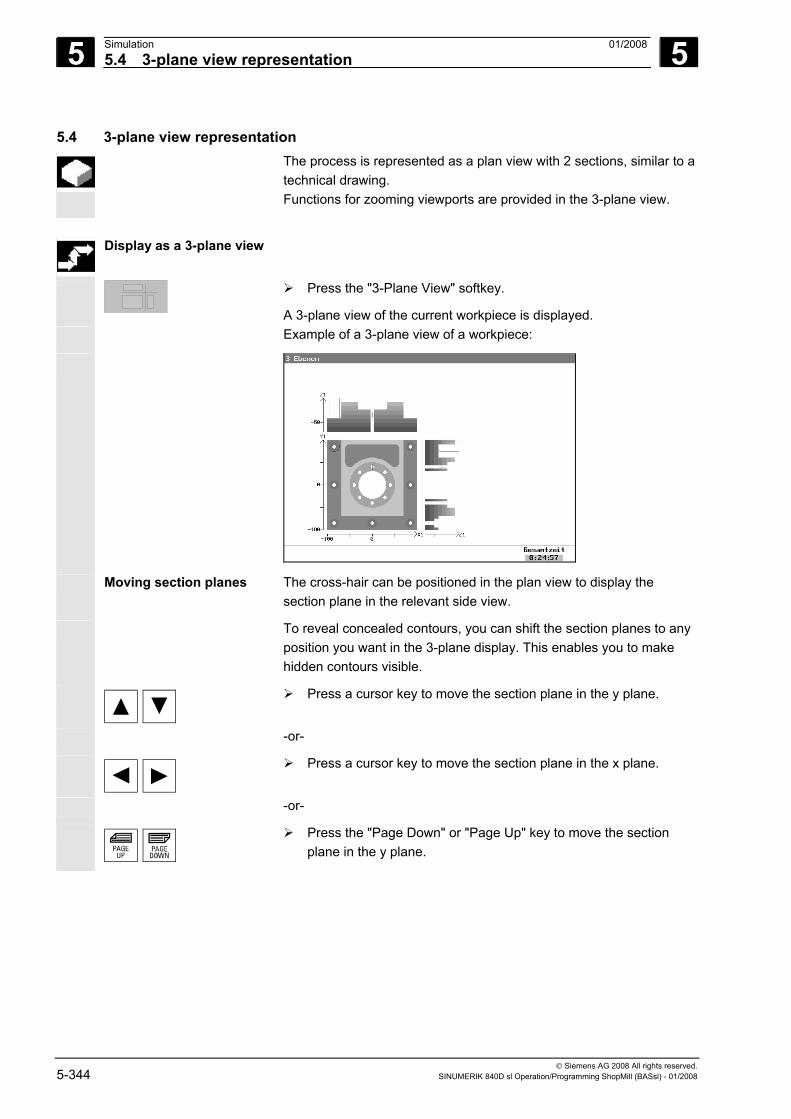
5 Simulation 01/2008 5.4 3-plane view representation
5
© Siemens AG 2008 All rights reserved. 5-344 SINUMERIK 840D sl Operation/Programming ShopMill (BASsl) - 01/2008
5.4 3-plane view representation
The process is represented as a plan view with 2 sections, similar to a technical drawing. Functions for zooming viewports are provided in the 3-plane view.
Display as a 3-plane view
Press the "3-Plane View" softkey.
A 3-plane view of the current workpiece is displayed. Example of a 3-plane view of a workpiece:
Moving section planes The cross-hair can be positioned in the plan view to display the section plane in the relevant side view.
To reveal concealed contours, you can shift the section planes to any position you want in the 3-plane display. This enables you to make hidden contours visible.
Press a cursor key to move the section plane in the y plane.
-or-
Press a cursor key to move the section plane in the x plane.
-or-
Press the "Page Down" or "Page Up" key to move the section plane in the y plane.
5 01/2008 Simulation5.5 Enlarging the viewport
5
© Siemens AG 2008 All rights reserved. SINUMERIK 840D sl Operation/Programming ShopMill (BASsl) - 01/2008 5-345
5.5 Enlarging the viewport Functions for displaying a more detailed representation of a workpiece
are available
• in the plan view and • in the 3-plane display.
Details
Press the "Details" softkey.
-and- Zoom
+ or
+
Press the "Zoom +" softkey or the "+" key to enlarge the viewport.
-or Zoom
- or
Press the "Zoom -" softkey or the "-" key to reduce the viewport.
-or- Auto
Zoom Press the "Auto Zoom" softkey to fit the viewport to the size of the
window automatically.
-or- Back to
original Press the "Back to original" softkey to restore the original size of
the viewport.
-or-
Press a cursor key to move the viewport right, left, up, or down.
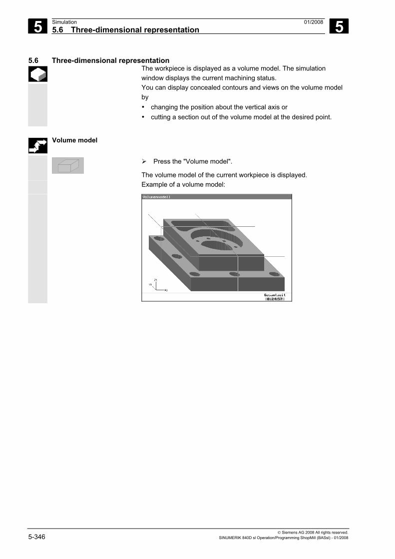
5 Simulation 01/2008 5.6 Three-dimensional representation
5
© Siemens AG 2008 All rights reserved. 5-346 SINUMERIK 840D sl Operation/Programming ShopMill (BASsl) - 01/2008
5.6 Three-dimensional representation The workpiece is displayed as a volume model. The simulation
window displays the current machining status. You can display concealed contours and views on the volume model by • changing the position about the vertical axis or • cutting a section out of the volume model at the desired point.
Volume model
Press the "Volume model".
The volume model of the current workpiece is displayed. Example of a volume model:
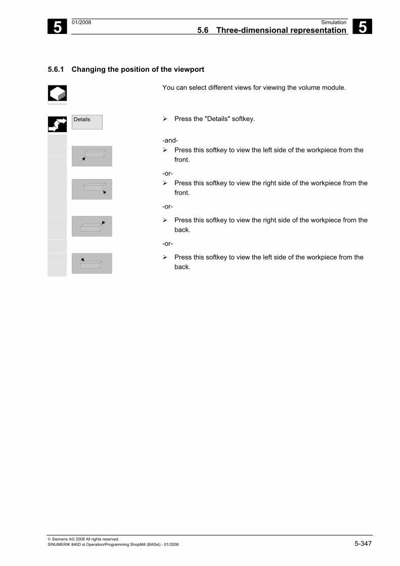
5 01/2008 Simulation5.6 Three-dimensional representation
5
© Siemens AG 2008 All rights reserved. SINUMERIK 840D sl Operation/Programming ShopMill (BASsl) - 01/2008 5-347
5.6.1 Changing the position of the viewport
You can select different views for viewing the volume module.
Details
Press the "Details" softkey.
-and-
Press this softkey to view the left side of the workpiece from the front.
-or-
Press this softkey to view the right side of the workpiece from the front.
-or-
Press this softkey to view the right side of the workpiece from the back.
-or-
Press this softkey to view the left side of the workpiece from the back.
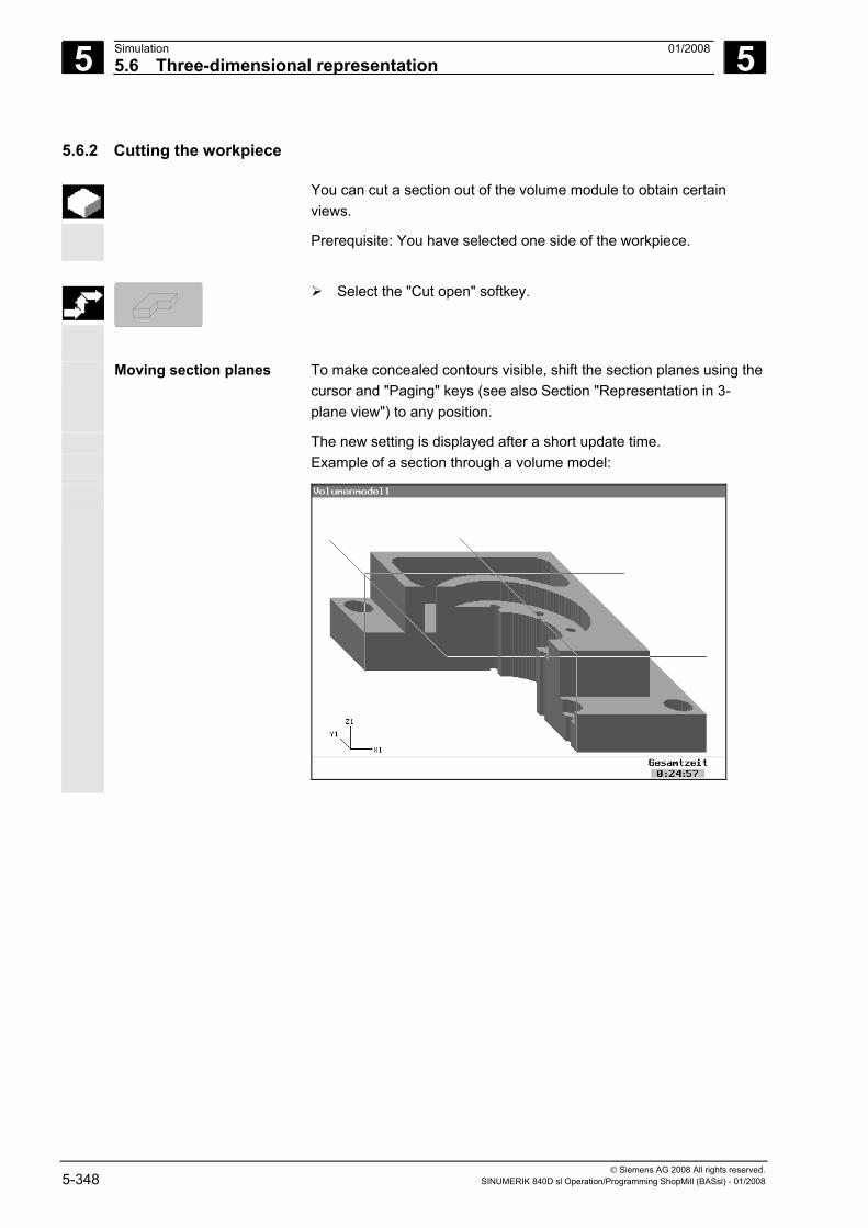
5 Simulation 01/2008 5.6 Three-dimensional representation
5
© Siemens AG 2008 All rights reserved. 5-348 SINUMERIK 840D sl Operation/Programming ShopMill (BASsl) - 01/2008
5.6.2 Cutting the workpiece
You can cut a section out of the volume module to obtain certain views.
Prerequisite: You have selected one side of the workpiece.
Select the "Cut open" softkey.
Moving section planes To make concealed contours visible, shift the section planes using the cursor and "Paging" keys (see also Section "Representation in 3-plane view") to any position.
The new setting is displayed after a short update time. Example of a section through a volume model:
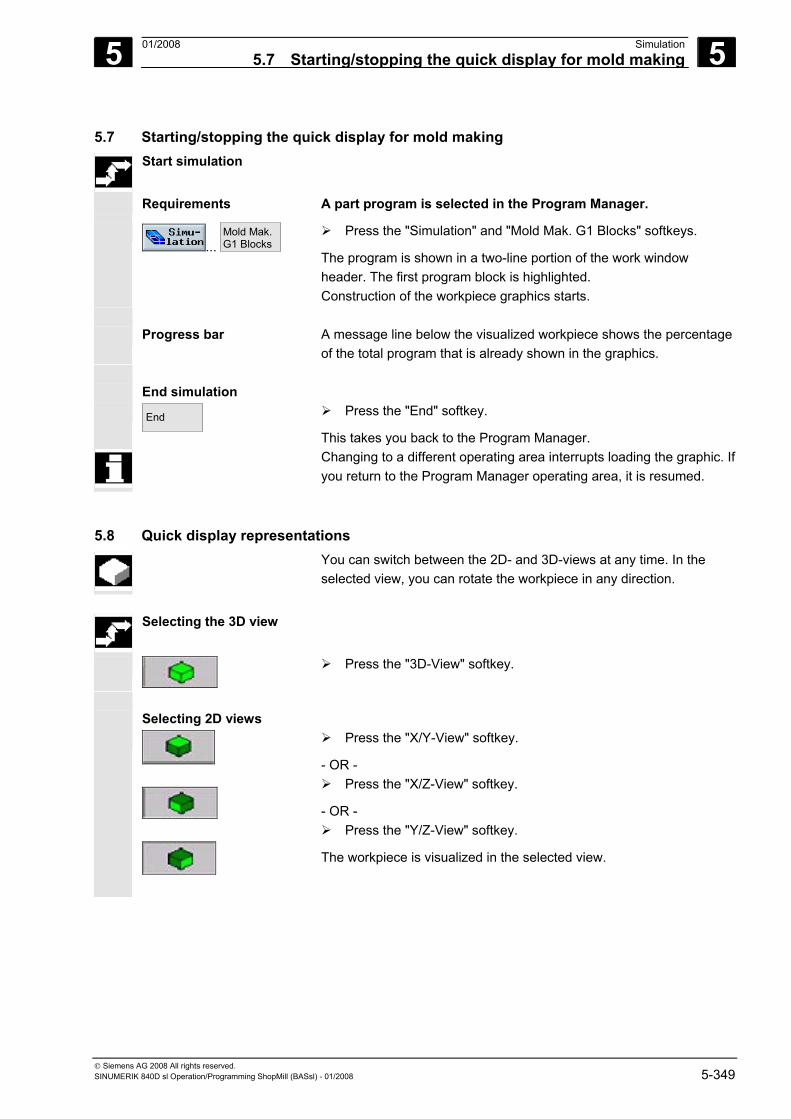
5 01/2008 Simulation5.7 Starting/stopping the quick display for mold making
5
© Siemens AG 2008 All rights reserved. SINUMERIK 840D sl Operation/Programming ShopMill (BASsl) - 01/2008 5-349
5.7 Starting/stopping the quick display for mold making Start simulation
Requirements A part program is selected in the Program Manager.
...
Mold Mak. G1 Blocks
Press the "Simulation" and "Mold Mak. G1 Blocks" softkeys.
The program is shown in a two-line portion of the work window header. The first program block is highlighted. Construction of the workpiece graphics starts.
Progress bar A message line below the visualized workpiece shows the percentage
of the total program that is already shown in the graphics. End simulation End
Press the "End" softkey.
This takes you back to the Program Manager. Changing to a different operating area interrupts loading the graphic. If
you return to the Program Manager operating area, it is resumed.
5.8 Quick display representations You can switch between the 2D- and 3D-views at any time. In the
selected view, you can rotate the workpiece in any direction.
Selecting the 3D view
Press the "3D-View" softkey.
Selecting 2D views
Press the "X/Y-View" softkey.
- OR - Press the "X/Z-View" softkey.
- OR - Press the "Y/Z-View" softkey.
The workpiece is visualized in the selected view.
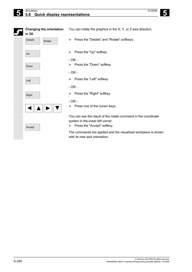
5 Simulation 01/2008 5.8 Quick display representations
5
© Siemens AG 2008 All rights reserved. 5-350 SINUMERIK 840D sl Operation/Programming ShopMill (BASsl) - 01/2008
Changing the orientation in 3D
You can rotate the graphics in the X, Y, or Z axis direction.
Details
Rotate
Press the "Details" and "Rotate" softkeys.
Up
Press the "Up" softkey.
- OR - Down
Press the "Down" softkey.
- OR -
Left
Press the "Left" softkey.
- OR -
Right
Press the "Right" softkey.
- OR -
Press one of the cursor keys.
You can see the result of the rotate command in the coordinate system in the lower left corner.
Accept
Press the "Accept" softkey.
The commands are applied and the visualized workpiece is shown with its new axis orientation.
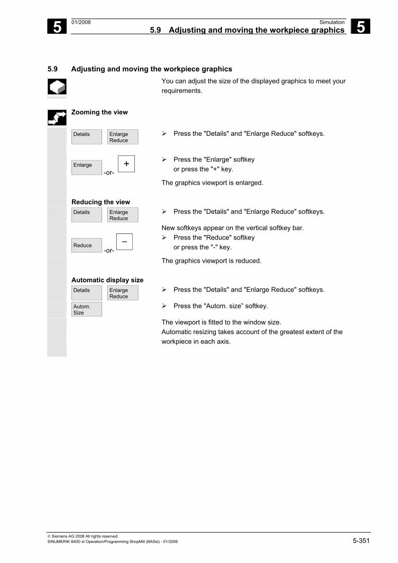
5 01/2008 Simulation5.9 Adjusting and moving the workpiece graphics
5
© Siemens AG 2008 All rights reserved. SINUMERIK 840D sl Operation/Programming ShopMill (BASsl) - 01/2008 5-351
5.9 Adjusting and moving the workpiece graphics You can adjust the size of the displayed graphics to meet your
requirements.
Zooming the view
Details
Enlarge Reduce
Press the "Details" and "Enlarge Reduce" softkeys.
Enlarge
-or- +
Press the "Enlarge" softkey or press the "+" key.
The graphics viewport is enlarged. Reducing the view Details
Enlarge Reduce
Press the "Details" and "Enlarge Reduce" softkeys.
New softkeys appear on the vertical softkey bar.
Reduce -or-
Press the "Reduce" softkey or press the "-" key.
The graphics viewport is reduced. Automatic display size Details
Enlarge Reduce
Press the "Details" and "Enlarge Reduce" softkeys.
Autom. Size
Press the "Autom. size” softkey.
The viewport is fitted to the window size. Automatic resizing takes account of the greatest extent of the workpiece in each axis.
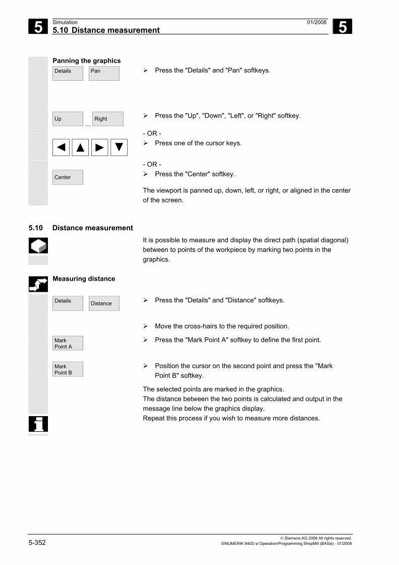
5 Simulation 01/2008 5.10 Distance measurement
5
© Siemens AG 2008 All rights reserved. 5-352 SINUMERIK 840D sl Operation/Programming ShopMill (BASsl) - 01/2008
Panning the graphics Details
Pan
Press the "Details" and "Pan" softkeys.
Up ...
Right
Press the "Up", "Down", "Left", or "Right" softkey.
- OR -
Press one of the cursor keys.
- OR - Center
Press the "Center" softkey.
The viewport is panned up, down, left, or right, or aligned in the center of the screen.
5.10 Distance measurement It is possible to measure and display the direct path (spatial diagonal)
between to points of the workpiece by marking two points in the graphics.
Measuring distance
Details
Distance
Press the "Details" and "Distance" softkeys.
Move the cross-hairs to the required position.
Mark Point A
Press the "Mark Point A" softkey to define the first point.
Mark Point B
Position the cursor on the second point and press the "Mark Point B" softkey.
The selected points are marked in the graphics. The distance between the two points is calculated and output in the message line below the graphics display.
Repeat this process if you wish to measure more distances.
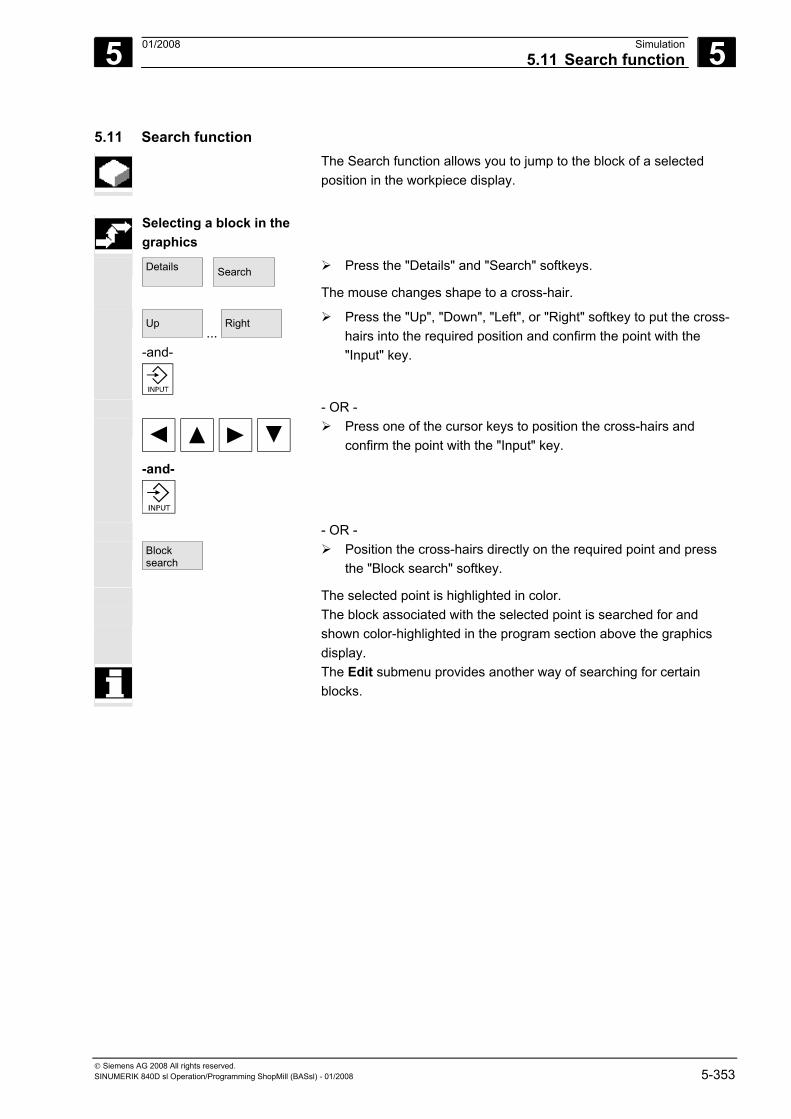
5 01/2008 Simulation5.11 Search function
5
© Siemens AG 2008 All rights reserved. SINUMERIK 840D sl Operation/Programming ShopMill (BASsl) - 01/2008 5-353
5.11 Search function The Search function allows you to jump to the block of a selected
position in the workpiece display.
Selecting a block in the
graphics
Details
Search
Press the "Details" and "Search" softkeys.
The mouse changes shape to a cross-hair.
Up ...
Right
-and-
Press the "Up", "Down", "Left", or "Right" softkey to put the cross-hairs into the required position and confirm the point with the "Input" key.
- OR -
-and-
Press one of the cursor keys to position the cross-hairs and confirm the point with the "Input" key.
- OR - Block
search Position the cross-hairs directly on the required point and press
the "Block search" softkey.
The selected point is highlighted in color. The block associated with the selected point is searched for and
shown color-highlighted in the program section above the graphics display.
The Edit submenu provides another way of searching for certain blocks.
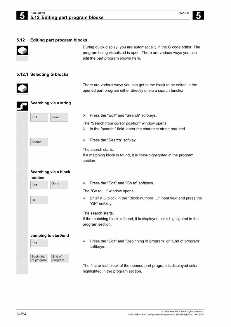
5 Simulation 01/2008 5.12 Editing part program blocks
5
© Siemens AG 2008 All rights reserved. 5-354 SINUMERIK 840D sl Operation/Programming ShopMill (BASsl) - 01/2008
5.12 Editing part program blocks During quick display, you are automatically in the G code editor. The
program being visualized is open. There are various ways you can edit the part program shown here.
5.12.1 Selecting G blocks
There are various ways you can get to the block to be edited in the opened part program either directly or via a search function.
Searching via a string
Edit
Search
Press the "Edit" and "Search" softkeys.
The "Search from cursor position" window opens.
In the "search:" field, enter the character string required.
Search
Press the "Search" softkey.
The search starts. If a matching block is found, it is color-highlighted in the program section.
Searching via a block
number
Edit
Go to
Press the "Edit" and "Go to" softkeys.
The "Go to …" window opens.
Ok
Enter a G block in the "Block number …" input field and press the "OK" softkey.
The search starts. If the matching block is found, it is displayed color-highlighted in the program section.
Jumping to start/end Edit
Beginning of program
End of program
Press the "Edit" and "Beginning of program" or "End of program" softkeys.
The first or last block of the opened part program is displayed color-highlighted in the program section.
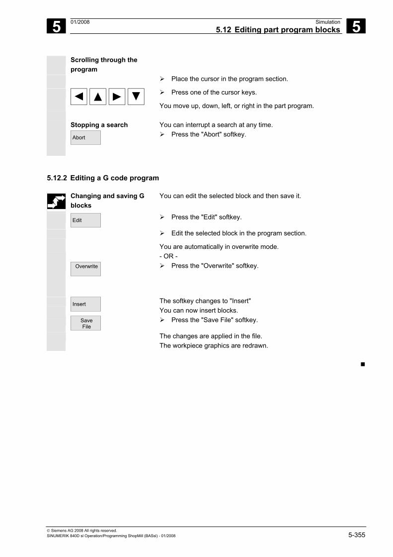
5 01/2008 Simulation5.12 Editing part program blocks
5
© Siemens AG 2008 All rights reserved. SINUMERIK 840D sl Operation/Programming ShopMill (BASsl) - 01/2008 5-355
Scrolling through the program
Place the cursor in the program section.
Press one of the cursor keys.
You move up, down, left, or right in the part program. Stopping a search You can interrupt a search at any time. Abort
Press the "Abort" softkey.
5.12.2 Editing a G code program
Changing and saving G blocks
You can edit the selected block and then save it.
Edit
Press the "Edit" softkey.
Edit the selected block in the program section.
You are automatically in overwrite mode. - OR - Overwrite
Press the "Overwrite" softkey.
Insert
The softkey changes to "Insert" You can now insert blocks.
Save File
Press the "Save File" softkey.
The changes are applied in the file. The workpiece graphics are redrawn.
5 Simulation 01/2008 5.12 Editing part program blocks
5
© Siemens AG 2008 All rights reserved. 5-356 SINUMERIK 840D sl Operation/Programming ShopMill (BASsl) - 01/2008
Notes
6 01/2008 File Management 6
© Siemens AG 2008 All rights reserved. SINUMERIK 840D sl Operation/Programming ShopMill (BASsl) - 01/2008 6-357
File Management 6.1 Managing programs with ShopMill.......................................................................... 6-358
6.2 Managing programs with ShopMill on NCU (HMI Embedded sl)............................ 6-359 6.2.1 Opening a program ................................................................................................. 6-361 6.2.2 Executing a program............................................................................................... 6-362 6.2.3 Multiple clamping .................................................................................................... 6-362 6.2.4 Executing a G code program from the network drive ............................................. 6-365 6.2.5 Creating a new directory/program........................................................................... 6-366 6.2.6 Selecting several programs .................................................................................... 6-367 6.2.7 Copying/Renaming a directory/program................................................................. 6-368 6.2.8 Deleting a directory/program................................................................................... 6-369 6.2.9 Saving/Reading in tool/zero point data ................................................................... 6-370
6.3 Managing programs with PCU 50.3 (HMI Advanced)............................................. 6-373 6.3.1 Opening a program ................................................................................................. 6-375 6.3.2 Executing a program............................................................................................... 6-376 6.3.3 Multiple clamping .................................................................................................... 6-376 6.3.4 Loading/Unloading a program................................................................................. 6-379 6.3.5 Executing a G code program from a hard disk or floppy disk/network drive .......... 6-380 6.3.6 Creating a new directory/program........................................................................... 6-381 6.3.7 Selecting several programs .................................................................................... 6-382 6.3.8 Copying/Renaming/Moving a directory/program .................................................... 6-383 6.3.9 Deleting a directory/program................................................................................... 6-385 6.3.10 Saving/Reading in tool/zero point data ................................................................... 6-385
6 File Management 01/2008 6.1 Managing programs with ShopMill
6
© Siemens AG 2008 All rights reserved. 6-358 SINUMERIK 840D sl Operation/Programming ShopMill (BASsl) - 01/2008
6.1 Managing programs with ShopMill All programs that you have created in ShopMill for machining
workpieces are stored in the NCK main memory. You can access these programs at any time via the Program Manager for execution, editing, copying, or renaming. Programs that you no longer require can be deleted to release their storage space.
ShopMill offers several options for exchanging programs and data withother workstations:
• Own hard disk (PCU 50.3 only) • CompactFlash card • Disk drive (PCU 50.3 only) • USB network connection
The following sections explain the program management of ShopMill on NCU (HMI Embedded sl) or PCU 50.3 (HMI Advanced). Find out which version of ShopMill you are running and then read either Section "Managing Program with ShopMill on NCU (HMI Embedded sl)" or "Managing Programs with PCU 50.3 (HMI Advanced)".
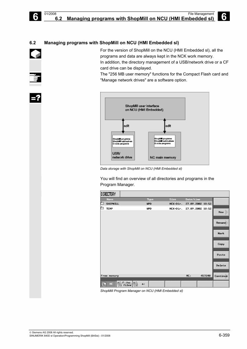
6 01/2008 File Management6.2 Managing programs with ShopMill on NCU (HMI Embedded sl)
6
© Siemens AG 2008 All rights reserved. SINUMERIK 840D sl Operation/Programming ShopMill (BASsl) - 01/2008 6-359
6.2 Managing programs with ShopMill on NCU (HMI Embedded sl) For the version of ShopMill on the NCU (HMI Embedded sl), all the
programs and data are always kept in the NCK work memory. In addition, the directory management of a USB/network drive or a CF card drive can be displayed.
The "256 MB user memory" functions for the Compact Flash card and "Manage network drives" are a software option.
Data storage with ShopMill on NCU (HMI Embedded sl)
You will find an overview of all directories and programs in the Program Manager.
ShopMill Program Manager on NCU (HMI Embedded sl)
6 File Management 01/2008 6.2 Managing programs with ShopMill on NCU (HMI Embedded sl)
6
© Siemens AG 2008 All rights reserved. 6-360 SINUMERIK 840D sl Operation/Programming ShopMill (BASsl) - 01/2008
In the horizontal softkey bar, you can select the storage medium that contains the directories and programs that you want to display. In addition to the "NC" softkey, which displays the data of the NCK main memory, 8 other softkeys can also be assigned. You can display the directories and programs on floppy disks and network drives:
Please also refer to the machine manufacturer's instructions. In the overview, the symbols in the left-hand column have the
following meaning:
Directory
Program
Zero point/tool data
The directories and programs are always listed complete with the following information: • Name
The name can be up to 24 characters long. For data transfer to external systems, the name is truncated to 8 characters.
• Type Directory: WPD Program: MPF Zero point/tool data: INI
• Size (in bytes) • Date/time (of creation or last change)
ShopMill stores the programs that are created internally for calculating the stock removal processes in the "TEMP" directory.
Above the horizontal softkey bar, you will find specifications for memory space management in the NCK.
You can find additional information for data-handling, selecting and executing a program in:
References: /BEMsl/ Operating Manual HMI Embedded sl SINUMERIK 840D sl
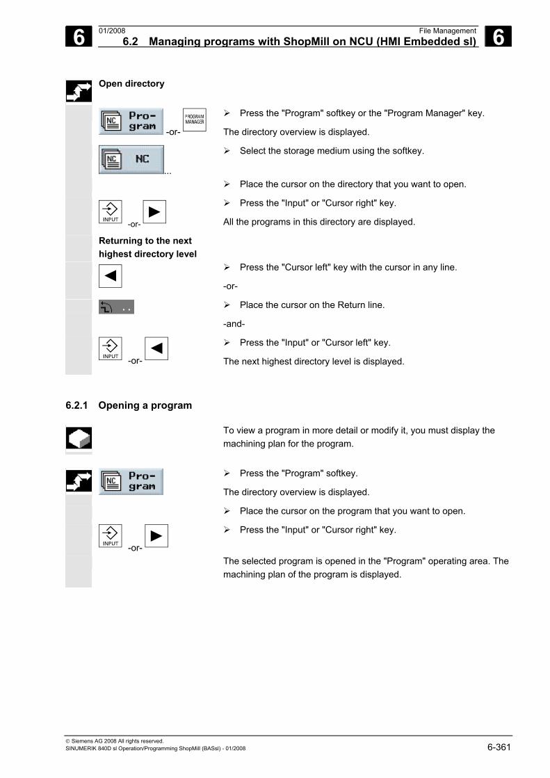
6 01/2008 File Management6.2 Managing programs with ShopMill on NCU (HMI Embedded sl)
6
© Siemens AG 2008 All rights reserved. SINUMERIK 840D sl Operation/Programming ShopMill (BASsl) - 01/2008 6-361
Open directory
-or-
Press the "Program" softkey or the "Program Manager" key.
The directory overview is displayed.
...
Select the storage medium using the softkey.
Place the cursor on the directory that you want to open.
-or-
Press the "Input" or "Cursor right" key.
All the programs in this directory are displayed.
Returning to the next highest directory level
Press the "Cursor left" key with the cursor in any line.
-or-
Place the cursor on the Return line.
-and-
-or-
Press the "Input" or "Cursor left" key.
The next highest directory level is displayed.
6.2.1 Opening a program
To view a program in more detail or modify it, you must display the machining plan for the program.
Press the "Program" softkey.
The directory overview is displayed.
Place the cursor on the program that you want to open.
-or-
Press the "Input" or "Cursor right" key.
The selected program is opened in the "Program" operating area. The machining plan of the program is displayed.
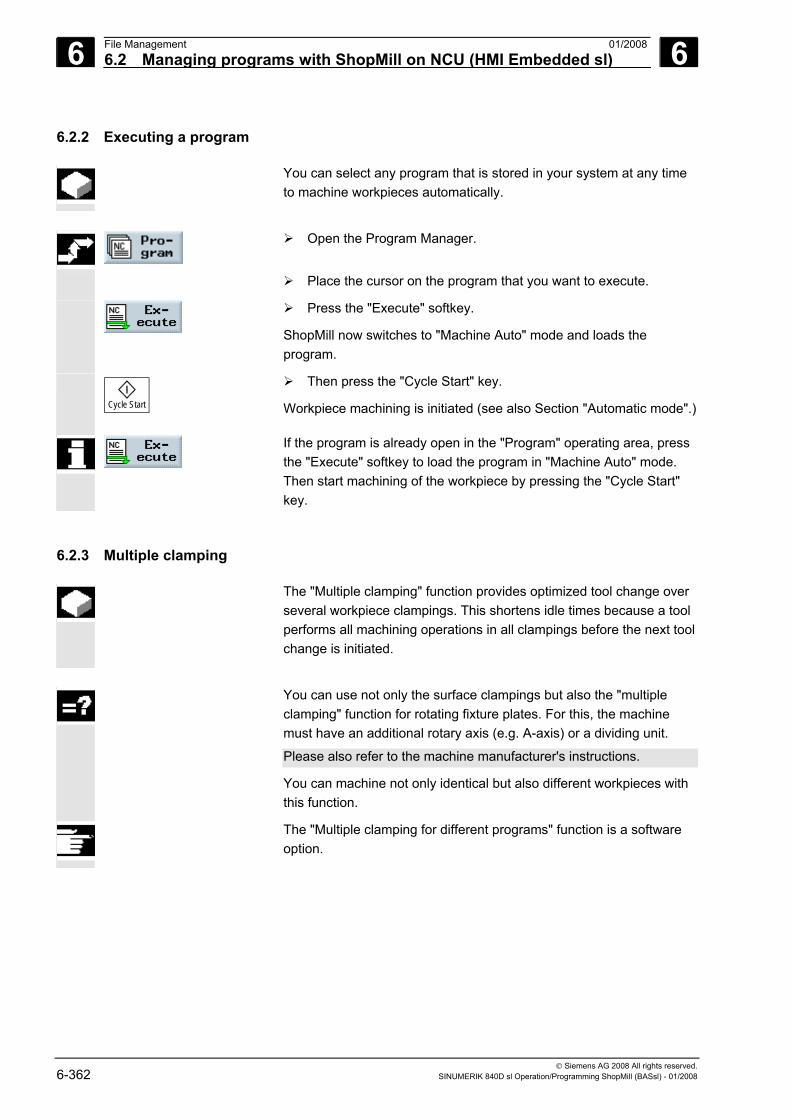
6 File Management 01/2008 6.2 Managing programs with ShopMill on NCU (HMI Embedded sl)
6
© Siemens AG 2008 All rights reserved. 6-362 SINUMERIK 840D sl Operation/Programming ShopMill (BASsl) - 01/2008
6.2.2 Executing a program
You can select any program that is stored in your system at any time to machine workpieces automatically.
Open the Program Manager.
Place the cursor on the program that you want to execute.
Press the "Execute" softkey.
ShopMill now switches to "Machine Auto" mode and loads the program.
Cycle Start
Then press the "Cycle Start" key.
Workpiece machining is initiated (see also Section "Automatic mode".)
If the program is already open in the "Program" operating area, press the "Execute" softkey to load the program in "Machine Auto" mode. Then start machining of the workpiece by pressing the "Cycle Start" key.
6.2.3 Multiple clamping
The "Multiple clamping" function provides optimized tool change over several workpiece clampings. This shortens idle times because a tool performs all machining operations in all clampings before the next tool change is initiated.
You can use not only the surface clampings but also the "multiple
clamping" function for rotating fixture plates. For this, the machine must have an additional rotary axis (e.g. A-axis) or a dividing unit.
Please also refer to the machine manufacturer's instructions.
You can machine not only identical but also different workpieces with this function.
The "Multiple clamping for different programs" function is a software option.
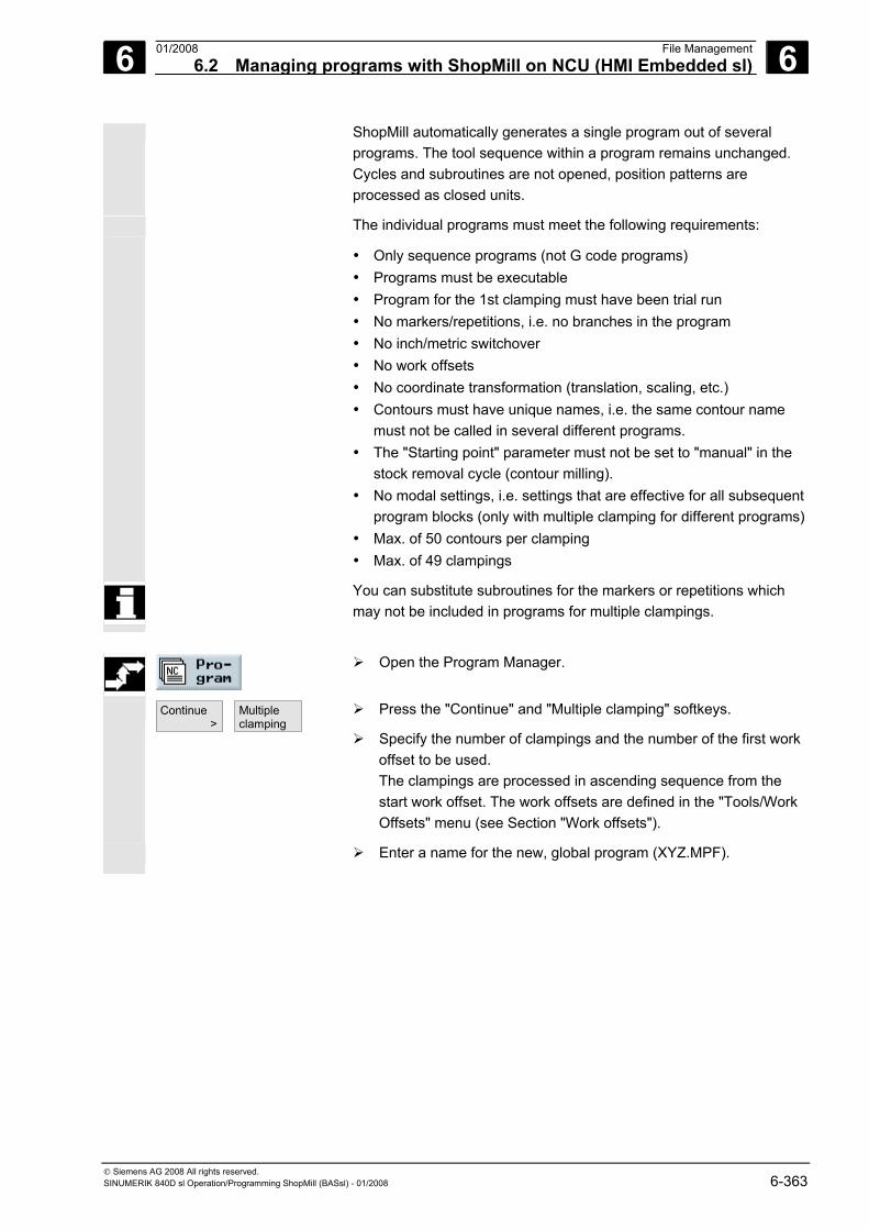
6 01/2008 File Management6.2 Managing programs with ShopMill on NCU (HMI Embedded sl)
6
© Siemens AG 2008 All rights reserved. SINUMERIK 840D sl Operation/Programming ShopMill (BASsl) - 01/2008 6-363
ShopMill automatically generates a single program out of several programs. The tool sequence within a program remains unchanged. Cycles and subroutines are not opened, position patterns are processed as closed units.
The individual programs must meet the following requirements:
• Only sequence programs (not G code programs) • Programs must be executable • Program for the 1st clamping must have been trial run • No markers/repetitions, i.e. no branches in the program • No inch/metric switchover • No work offsets • No coordinate transformation (translation, scaling, etc.) • Contours must have unique names, i.e. the same contour name
must not be called in several different programs. • The "Starting point" parameter must not be set to "manual" in the
stock removal cycle (contour milling). • No modal settings, i.e. settings that are effective for all subsequent
program blocks (only with multiple clamping for different programs)• Max. of 50 contours per clamping • Max. of 49 clampings
You can substitute subroutines for the markers or repetitions which may not be included in programs for multiple clampings.
Open the Program Manager.
Continue >
Multipleclamping
Press the "Continue" and "Multiple clamping" softkeys.
Specify the number of clampings and the number of the first work offset to be used. The clampings are processed in ascending sequence from the start work offset. The work offsets are defined in the "Tools/Work Offsets" menu (see Section "Work offsets").
Enter a name for the new, global program (XYZ.MPF).
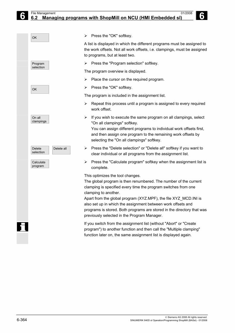
6 File Management 01/2008 6.2 Managing programs with ShopMill on NCU (HMI Embedded sl)
6
© Siemens AG 2008 All rights reserved. 6-364 SINUMERIK 840D sl Operation/Programming ShopMill (BASsl) - 01/2008
OK
Press the "OK" softkey.
A list is displayed in which the different programs must be assigned to the work offsets. Not all work offsets, i.e. clampings, must be assigned to programs, but at least two.
Programselection
Press the "Program selection" softkey.
The program overview is displayed.
Place the cursor on the required program.
OK
Press the "OK" softkey.
The program is included in the assignment list.
Repeat this process until a program is assigned to every required work offset.
On allclampings
If you wish to execute the same program on all clampings, select "On all clampings" softkey. You can assign different programs to individual work offsets first, and then assign one program to the remaining work offsets by selecting the "On all clampings" softkey.
Deleteselection
Delete all
Press the "Delete selection" or "Delete all" softkey if you want to clear individual or all programs from the assignment list.
Calculateprogram
Press the "Calculate program" softkey when the assignment list is complete.
This optimizes the tool changes. The global program is then renumbered. The number of the current clamping is specified every time the program switches from one clamping to another. Apart from the global program (XYZ.MPF), the file XYZ_MCD.INI is also set up in which the assignment between work offsets and programs is stored. Both programs are stored in the directory that was previously selected in the Program Manager.
If you switch from the assignment list (without "Abort" or "Create program") to another function and then call the "Multiple clamping" function later on, the same assignment list is displayed again.
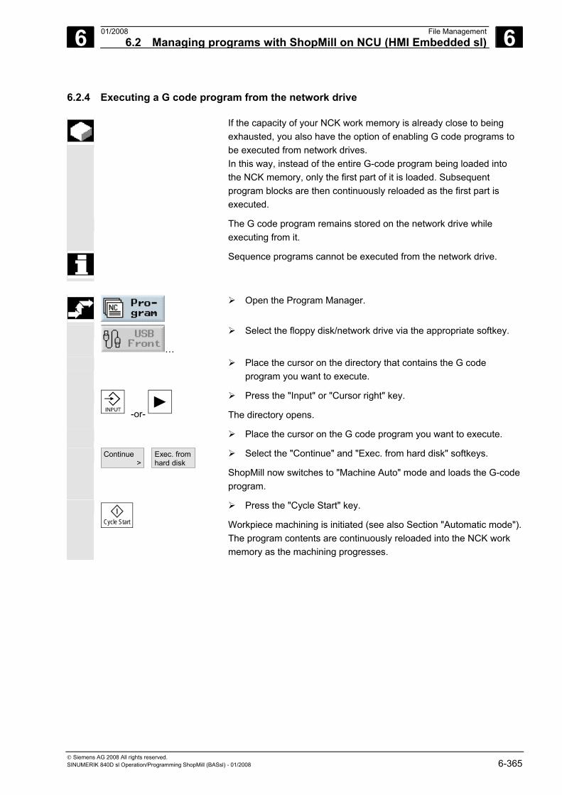
6 01/2008 File Management6.2 Managing programs with ShopMill on NCU (HMI Embedded sl)
6
© Siemens AG 2008 All rights reserved. SINUMERIK 840D sl Operation/Programming ShopMill (BASsl) - 01/2008 6-365
6.2.4 Executing a G code program from the network drive
If the capacity of your NCK work memory is already close to being exhausted, you also have the option of enabling G code programs to be executed from network drives. In this way, instead of the entire G-code program being loaded into the NCK memory, only the first part of it is loaded. Subsequent program blocks are then continuously reloaded as the first part is executed.
The G code program remains stored on the network drive while executing from it.
Sequence programs cannot be executed from the network drive.
Open the Program Manager.
…
Select the floppy disk/network drive via the appropriate softkey.
Place the cursor on the directory that contains the G code program you want to execute.
-or-
Press the "Input" or "Cursor right" key.
The directory opens.
Place the cursor on the G code program you want to execute.
Continue >
Exec. from hard disk
Select the "Continue" and "Exec. from hard disk" softkeys.
ShopMill now switches to "Machine Auto" mode and loads the G-code program.
Cycle Start
Press the "Cycle Start" key.
Workpiece machining is initiated (see also Section "Automatic mode"). The program contents are continuously reloaded into the NCK work memory as the machining progresses.
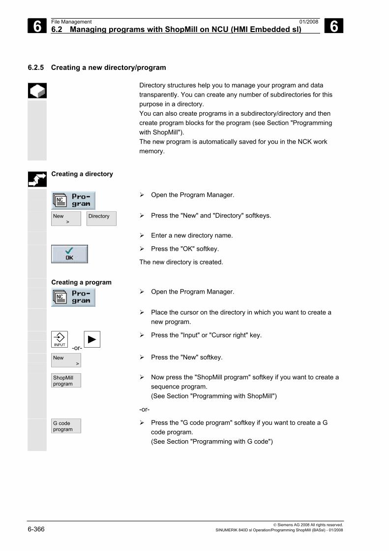
6 File Management 01/2008 6.2 Managing programs with ShopMill on NCU (HMI Embedded sl)
6
© Siemens AG 2008 All rights reserved. 6-366 SINUMERIK 840D sl Operation/Programming ShopMill (BASsl) - 01/2008
6.2.5 Creating a new directory/program
Directory structures help you to manage your program and data transparently. You can create any number of subdirectories for this purpose in a directory. You can also create programs in a subdirectory/directory and then create program blocks for the program (see Section "Programming with ShopMill"). The new program is automatically saved for you in the NCK work memory.
Creating a directory
Open the Program Manager.
New >
Directory
Press the "New" and "Directory" softkeys.
Enter a new directory name.
Press the "OK" softkey.
The new directory is created.
Creating a program
Open the Program Manager.
Place the cursor on the directory in which you want to create a new program.
-or-
Press the "Input" or "Cursor right" key.
New >
Press the "New" softkey.
ShopMillprogram
Now press the "ShopMill program" softkey if you want to create a sequence program. (See Section "Programming with ShopMill")
-or-
G codeprogram
Press the "G code program" softkey if you want to create a G code program. (See Section "Programming with G code")
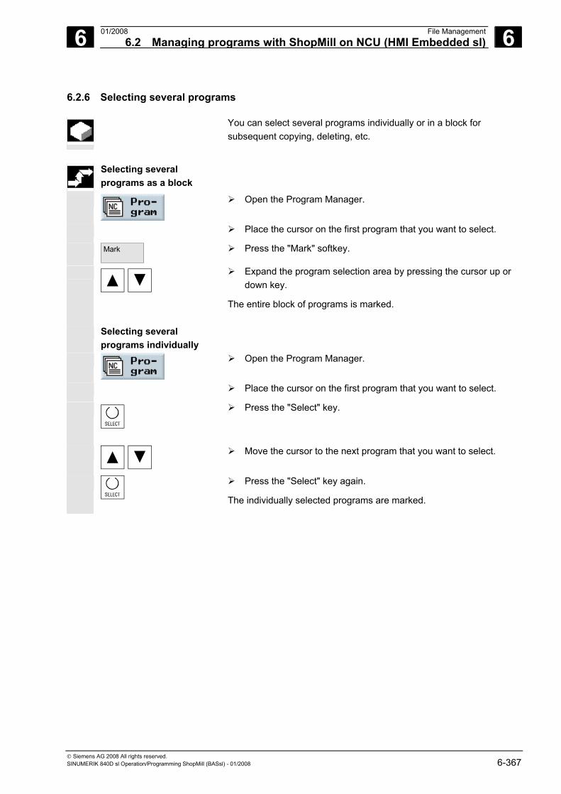
6 01/2008 File Management6.2 Managing programs with ShopMill on NCU (HMI Embedded sl)
6
© Siemens AG 2008 All rights reserved. SINUMERIK 840D sl Operation/Programming ShopMill (BASsl) - 01/2008 6-367
6.2.6 Selecting several programs
You can select several programs individually or in a block for subsequent copying, deleting, etc.
Selecting several
programs as a block
Open the Program Manager.
Place the cursor on the first program that you want to select.
Mark
Press the "Mark" softkey.
Expand the program selection area by pressing the cursor up or down key.
The entire block of programs is marked.
Selecting several programs individually
Open the Program Manager.
Place the cursor on the first program that you want to select.
Press the "Select" key.
Move the cursor to the next program that you want to select.
Press the "Select" key again.
The individually selected programs are marked.
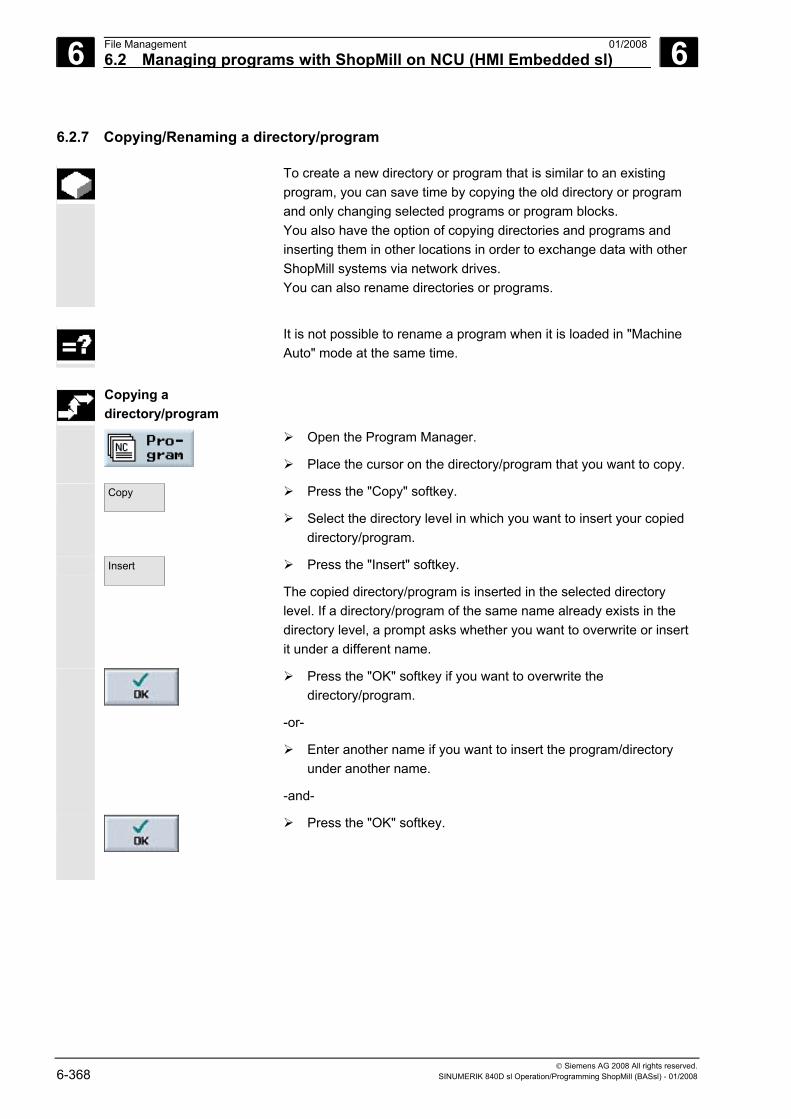
6 File Management 01/2008 6.2 Managing programs with ShopMill on NCU (HMI Embedded sl)
6
© Siemens AG 2008 All rights reserved. 6-368 SINUMERIK 840D sl Operation/Programming ShopMill (BASsl) - 01/2008
6.2.7 Copying/Renaming a directory/program
To create a new directory or program that is similar to an existing program, you can save time by copying the old directory or program and only changing selected programs or program blocks. You also have the option of copying directories and programs and inserting them in other locations in order to exchange data with other ShopMill systems via network drives. You can also rename directories or programs.
It is not possible to rename a program when it is loaded in "Machine
Auto" mode at the same time.
Copying a
directory/program
Open the Program Manager.
Place the cursor on the directory/program that you want to copy.
Copy
Press the "Copy" softkey.
Select the directory level in which you want to insert your copied directory/program.
Insert
Press the "Insert" softkey.
The copied directory/program is inserted in the selected directory level. If a directory/program of the same name already exists in the directory level, a prompt asks whether you want to overwrite or insert it under a different name.
Press the "OK" softkey if you want to overwrite the directory/program.
-or-
Enter another name if you want to insert the program/directory under another name.
-and-
Press the "OK" softkey.
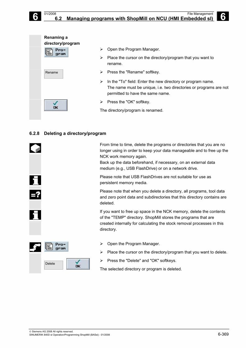
6 01/2008 File Management6.2 Managing programs with ShopMill on NCU (HMI Embedded sl)
6
© Siemens AG 2008 All rights reserved. SINUMERIK 840D sl Operation/Programming ShopMill (BASsl) - 01/2008 6-369
Renaming a directory/program
Open the Program Manager.
Place the cursor on the directory/program that you want to rename.
Rename
Press the "Rename" softkey.
In the "To" field: Enter the new directory or program name. The name must be unique, i.e. two directories or programs are not permitted to have the same name.
Press the "OK" softkey.
The directory/program is renamed.
6.2.8 Deleting a directory/program
From time to time, delete the programs or directories that you are no longer using in order to keep your data manageable and to free up the NCK work memory again. Back up the data beforehand, if necessary, on an external data medium (e.g., USB FlashDrive) or on a network drive.
Please note that USB FlashDrives are not suitable for use as persistent memory media.
Please note that when you delete a directory, all programs, tool data and zero point data and subdirectories that this directory contains are deleted.
If you want to free up space in the NCK memory, delete the contents of the "TEMP" directory. ShopMill stores the programs that are created internally for calculating the stock removal processes in this directory.
Open the Program Manager.
Place the cursor on the directory/program that you want to delete.
Delete
Press the "Delete" and "OK" softkeys.
The selected directory or program is deleted.
6 File Management 01/2008 6.2 Managing programs with ShopMill on NCU (HMI Embedded sl)
6
© Siemens AG 2008 All rights reserved. 6-370 SINUMERIK 840D sl Operation/Programming ShopMill (BASsl) - 01/2008
6.2.9 Saving/Reading in tool/zero point data
Apart from programs, you can also save tool data and zero point settings. You can use this function, for example, to back up the tool and zero point data for a specific sequence program. If you want to execute this program at a later point in time, you will then have quick access to the relevant settings.
Even tool data that you have measured on an external tool setting station can be copied easily into the tool management system using this option. For further details, see: References: /FBSPsl/, CNC Commissioning: ShopMill, SINUMERIK 840D sl
You can choose which data you want to back up:
• Tool data • Magazine loading • Zero points • Basic zero point
You can also specify the amount of data to be backed up: • Complete tool list or all zero points • All tool data or zero points used in the program
You can only read out the magazine assignments if your system provides support for loading and unloading tool data to and from the tool-holding magazine (see Section "Loading/unloading tools").
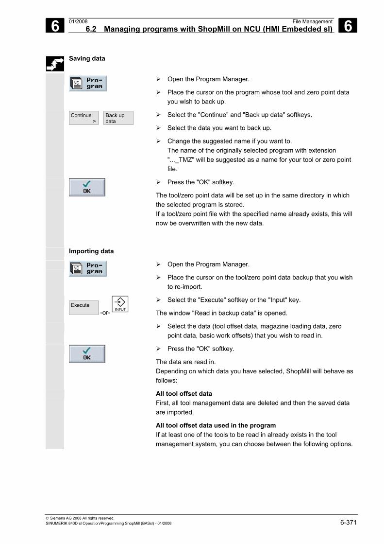
6 01/2008 File Management6.2 Managing programs with ShopMill on NCU (HMI Embedded sl)
6
© Siemens AG 2008 All rights reserved. SINUMERIK 840D sl Operation/Programming ShopMill (BASsl) - 01/2008 6-371
Saving data
Open the Program Manager.
Place the cursor on the program whose tool and zero point data you wish to back up.
Continue >
Back up data
Select the "Continue" and "Back up data" softkeys.
Select the data you want to back up.
Change the suggested name if you want to. The name of the originally selected program with extension "..._TMZ" will be suggested as a name for your tool or zero point file.
Press the "OK" softkey.
The tool/zero point data will be set up in the same directory in which the selected program is stored. If a tool/zero point file with the specified name already exists, this will now be overwritten with the new data.
Importing data
Open the Program Manager.
Place the cursor on the tool/zero point data backup that you wish to re-import.
Execute
-or-
Select the "Execute" softkey or the "Input" key.
The window "Read in backup data" is opened.
Select the data (tool offset data, magazine loading data, zero point data, basic work offsets) that you wish to read in.
Press the "OK" softkey.
The data are read in. Depending on which data you have selected, ShopMill will behave as follows:
All tool offset data First, all tool management data are deleted and then the saved data are imported.
All tool offset data used in the program If at least one of the tools to be read in already exists in the tool management system, you can choose between the following options.
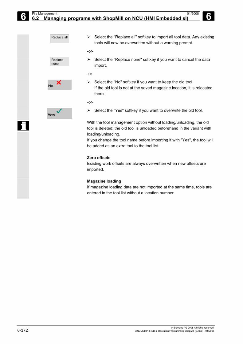
6 File Management 01/2008 6.2 Managing programs with ShopMill on NCU (HMI Embedded sl)
6
© Siemens AG 2008 All rights reserved. 6-372 SINUMERIK 840D sl Operation/Programming ShopMill (BASsl) - 01/2008
Replace all
Select the "Replace all" softkey to import all tool data. Any existing tools will now be overwritten without a warning prompt.
-or-
Replacenone
Select the "Replace none" softkey if you want to cancel the data import.
-or-
Select the "No" softkey if you want to keep the old tool. If the old tool is not at the saved magazine location, it is relocated there.
-or-
Select the "Yes" softkey if you want to overwrite the old tool.
With the tool management option without loading/unloading, the old tool is deleted; the old tool is unloaded beforehand in the variant with loading/unloading. If you change the tool name before importing it with "Yes", the tool will be added as an extra tool to the tool list.
Zero offsets Existing work offsets are always overwritten when new offsets are imported.
Magazine loading If magazine loading data are not imported at the same time, tools are entered in the tool list without a location number.
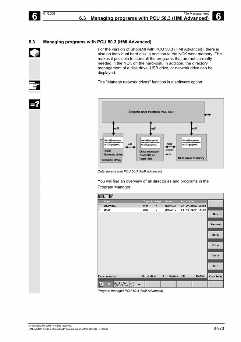
6 01/2008 File Management6.3 Managing programs with PCU 50.3 (HMI Advanced)
6
© Siemens AG 2008 All rights reserved. SINUMERIK 840D sl Operation/Programming ShopMill (BASsl) - 01/2008 6-373
6.3 Managing programs with PCU 50.3 (HMI Advanced) For the version of ShopMill with PCU 50.3 (HMI Advanced), there is
also an individual hard disk in addition to the NCK work memory. This makes it possible to store all the programs that are not currently needed in the NCK on the hard-disk. In addition, the directory management of a disk drive, USB drive, or network drive can be displayed.
The "Manage network drives" function is a software option.
Data storage with PCU 50.3 (HMI Advanced)
You will find an overview of all directories and programs in the Program Manager.
Program manager PCU 50.3 (HMI Advanced)
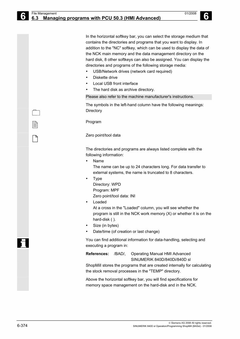
6 File Management 01/2008 6.3 Managing programs with PCU 50.3 (HMI Advanced)
6
© Siemens AG 2008 All rights reserved. 6-374 SINUMERIK 840D sl Operation/Programming ShopMill (BASsl) - 01/2008
In the horizontal softkey bar, you can select the storage medium that contains the directories and programs that you want to display. In addition to the "NC" softkey, which can be used to display the data of the NCK main memory and the data management directory on the hard disk, 8 other softkeys can also be assigned. You can display the directories and programs of the following storage media: • USB/Network drives (network card required) • Diskette drive • Local USB front interface • The hard disk as archive directory.
Please also refer to the machine manufacturer's instructions. The symbols in the left-hand column have the following meanings: Directory
Program
Zero point/tool data
The directories and programs are always listed complete with the following information: • Name
The name can be up to 24 characters long. For data transfer to external systems, the name is truncated to 8 characters.
• Type Directory: WPD Program: MPF Zero point/tool data: INI
• Loaded At a cross in the "Loaded" column, you will see whether the program is still in the NCK work memory (X) or whether it is on the hard-disk ( ).
• Size (in bytes) • Date/time (of creation or last change)
You can find additional information for data-handling, selecting and executing a program in:
References: /BAD/, Operating Manual HMI Advanced SINUMERIK 840D/840Di/840D sl
ShopMill stores the programs that are created internally for calculating the stock removal processes in the "TEMP" directory.
Above the horizontal softkey bar, you will find specifications for memory space management on the hard-disk and in the NCK.
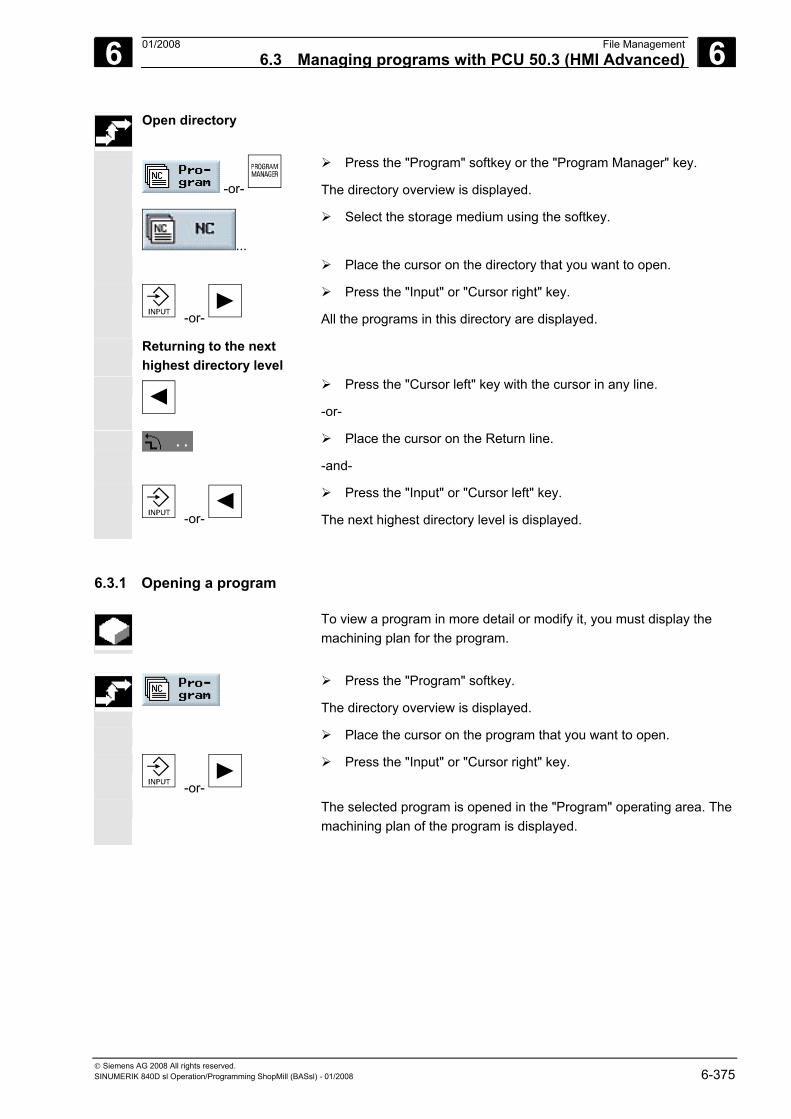
6 01/2008 File Management6.3 Managing programs with PCU 50.3 (HMI Advanced)
6
© Siemens AG 2008 All rights reserved. SINUMERIK 840D sl Operation/Programming ShopMill (BASsl) - 01/2008 6-375
Open directory
-or-
Press the "Program" softkey or the "Program Manager" key.
The directory overview is displayed.
...
Select the storage medium using the softkey.
Place the cursor on the directory that you want to open.
-or-
Press the "Input" or "Cursor right" key.
All the programs in this directory are displayed.
Returning to the next highest directory level
Press the "Cursor left" key with the cursor in any line.
-or-
Place the cursor on the Return line.
-and-
-or-
Press the "Input" or "Cursor left" key.
The next highest directory level is displayed.
6.3.1 Opening a program
To view a program in more detail or modify it, you must display the machining plan for the program.
Press the "Program" softkey.
The directory overview is displayed.
Place the cursor on the program that you want to open.
-or-
Press the "Input" or "Cursor right" key.
The selected program is opened in the "Program" operating area. The machining plan of the program is displayed.
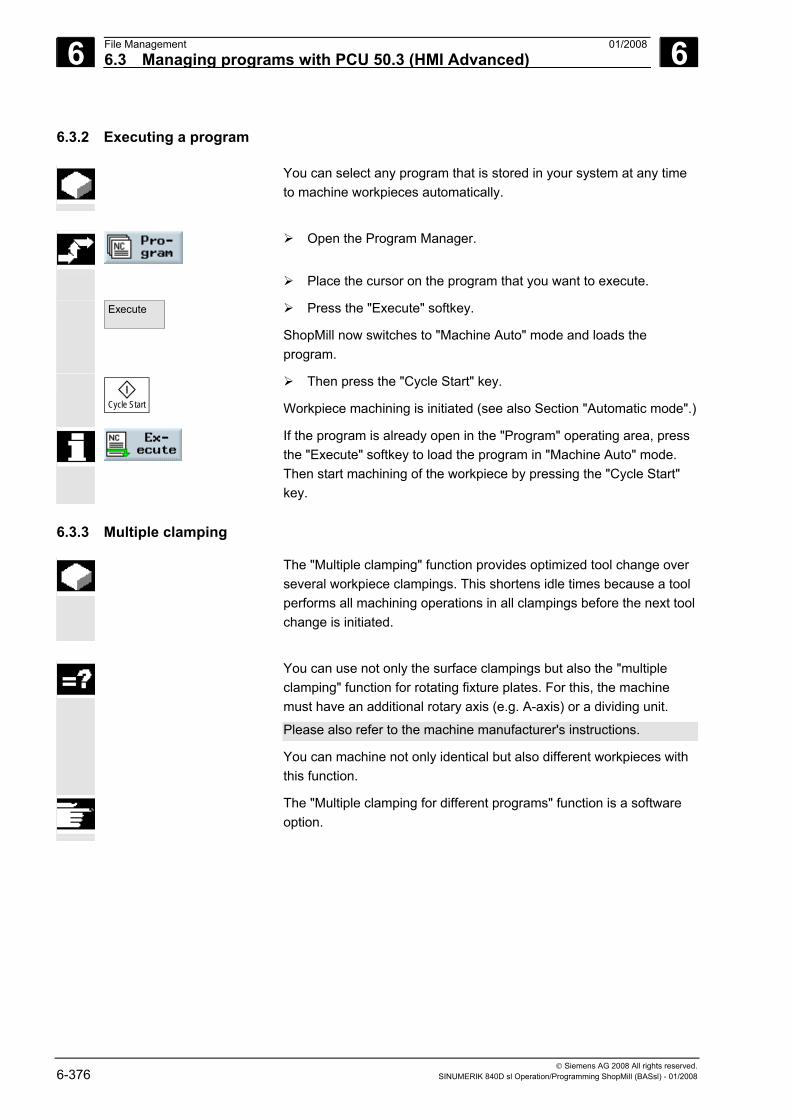
6 File Management 01/2008 6.3 Managing programs with PCU 50.3 (HMI Advanced)
6
© Siemens AG 2008 All rights reserved. 6-376 SINUMERIK 840D sl Operation/Programming ShopMill (BASsl) - 01/2008
6.3.2 Executing a program
You can select any program that is stored in your system at any time to machine workpieces automatically.
Open the Program Manager.
Place the cursor on the program that you want to execute.
Execute
Press the "Execute" softkey.
ShopMill now switches to "Machine Auto" mode and loads the program.
Cycle Start
Then press the "Cycle Start" key.
Workpiece machining is initiated (see also Section "Automatic mode".)
If the program is already open in the "Program" operating area, press the "Execute" softkey to load the program in "Machine Auto" mode. Then start machining of the workpiece by pressing the "Cycle Start" key.
6.3.3 Multiple clamping
The "Multiple clamping" function provides optimized tool change over several workpiece clampings. This shortens idle times because a tool performs all machining operations in all clampings before the next tool change is initiated.
You can use not only the surface clampings but also the "multiple
clamping" function for rotating fixture plates. For this, the machine must have an additional rotary axis (e.g. A-axis) or a dividing unit.
Please also refer to the machine manufacturer's instructions.
You can machine not only identical but also different workpieces with this function.
The "Multiple clamping for different programs" function is a software option.
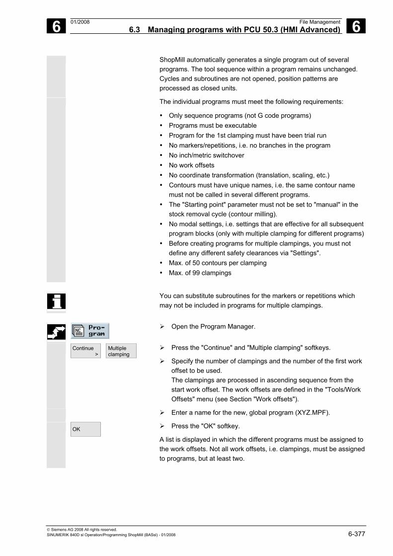
6 01/2008 File Management6.3 Managing programs with PCU 50.3 (HMI Advanced)
6
© Siemens AG 2008 All rights reserved. SINUMERIK 840D sl Operation/Programming ShopMill (BASsl) - 01/2008 6-377
ShopMill automatically generates a single program out of several programs. The tool sequence within a program remains unchanged. Cycles and subroutines are not opened, position patterns are processed as closed units.
The individual programs must meet the following requirements:
• Only sequence programs (not G code programs) • Programs must be executable • Program for the 1st clamping must have been trial run • No markers/repetitions, i.e. no branches in the program • No inch/metric switchover • No work offsets • No coordinate transformation (translation, scaling, etc.) • Contours must have unique names, i.e. the same contour name
must not be called in several different programs. • The "Starting point" parameter must not be set to "manual" in the
stock removal cycle (contour milling). • No modal settings, i.e. settings that are effective for all subsequent
program blocks (only with multiple clamping for different programs)• Before creating programs for multiple clampings, you must not
define any different safety clearances via "Settings". • Max. of 50 contours per clamping • Max. of 99 clampings
You can substitute subroutines for the markers or repetitions which
may not be included in programs for multiple clampings.
Open the Program Manager.
Continue >
Multipleclamping
Press the "Continue" and "Multiple clamping" softkeys.
Specify the number of clampings and the number of the first work offset to be used. The clampings are processed in ascending sequence from the start work offset. The work offsets are defined in the "Tools/Work Offsets" menu (see Section "Work offsets").
Enter a name for the new, global program (XYZ.MPF).
OK
Press the "OK" softkey.
A list is displayed in which the different programs must be assigned to the work offsets. Not all work offsets, i.e. clampings, must be assigned to programs, but at least two.
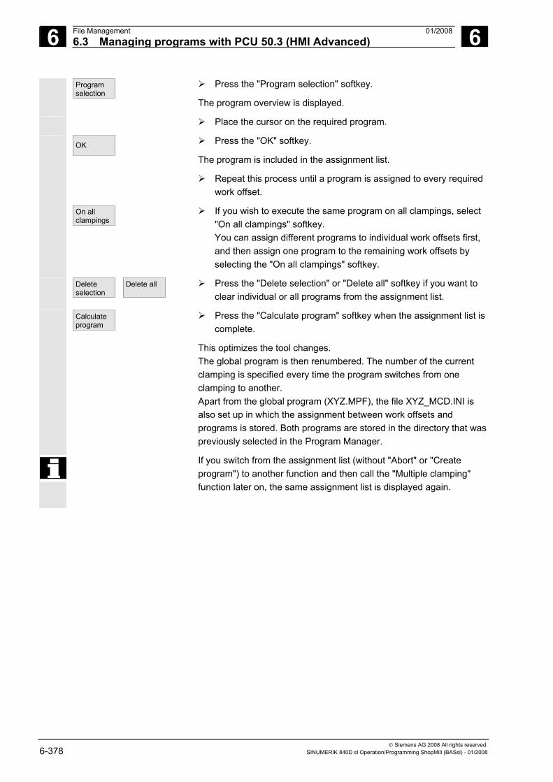
6 File Management 01/2008 6.3 Managing programs with PCU 50.3 (HMI Advanced)
6
© Siemens AG 2008 All rights reserved. 6-378 SINUMERIK 840D sl Operation/Programming ShopMill (BASsl) - 01/2008
Programselection
Press the "Program selection" softkey.
The program overview is displayed.
Place the cursor on the required program.
OK
Press the "OK" softkey.
The program is included in the assignment list.
Repeat this process until a program is assigned to every required work offset.
On allclampings
If you wish to execute the same program on all clampings, select "On all clampings" softkey. You can assign different programs to individual work offsets first, and then assign one program to the remaining work offsets by selecting the "On all clampings" softkey.
Deleteselection
Delete all
Press the "Delete selection" or "Delete all" softkey if you want to clear individual or all programs from the assignment list.
Calculateprogram
Press the "Calculate program" softkey when the assignment list is complete.
This optimizes the tool changes. The global program is then renumbered. The number of the current clamping is specified every time the program switches from one clamping to another. Apart from the global program (XYZ.MPF), the file XYZ_MCD.INI is also set up in which the assignment between work offsets and programs is stored. Both programs are stored in the directory that was previously selected in the Program Manager.
If you switch from the assignment list (without "Abort" or "Create program") to another function and then call the "Multiple clamping" function later on, the same assignment list is displayed again.
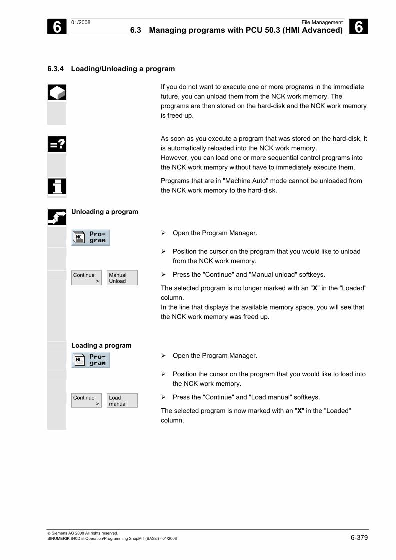
6 01/2008 File Management6.3 Managing programs with PCU 50.3 (HMI Advanced)
6
© Siemens AG 2008 All rights reserved. SINUMERIK 840D sl Operation/Programming ShopMill (BASsl) - 01/2008 6-379
6.3.4 Loading/Unloading a program
If you do not want to execute one or more programs in the immediate future, you can unload them from the NCK work memory. The programs are then stored on the hard-disk and the NCK work memory is freed up.
As soon as you execute a program that was stored on the hard-disk, it
is automatically reloaded into the NCK work memory. However, you can load one or more sequential control programs into the NCK work memory without have to immediately execute them.
Programs that are in "Machine Auto" mode cannot be unloaded from the NCK work memory to the hard-disk.
Unloading a program
Open the Program Manager.
Position the cursor on the program that you would like to unload from the NCK work memory.
Continue >
Manual Unload
Press the "Continue" and "Manual unload" softkeys.
The selected program is no longer marked with an "X" in the "Loaded" column. In the line that displays the available memory space, you will see that the NCK work memory was freed up.
Loading a program
Open the Program Manager.
Position the cursor on the program that you would like to load into the NCK work memory.
Continue >
Load manual
Press the "Continue" and "Load manual" softkeys.
The selected program is now marked with an "X" in the "Loaded" column.
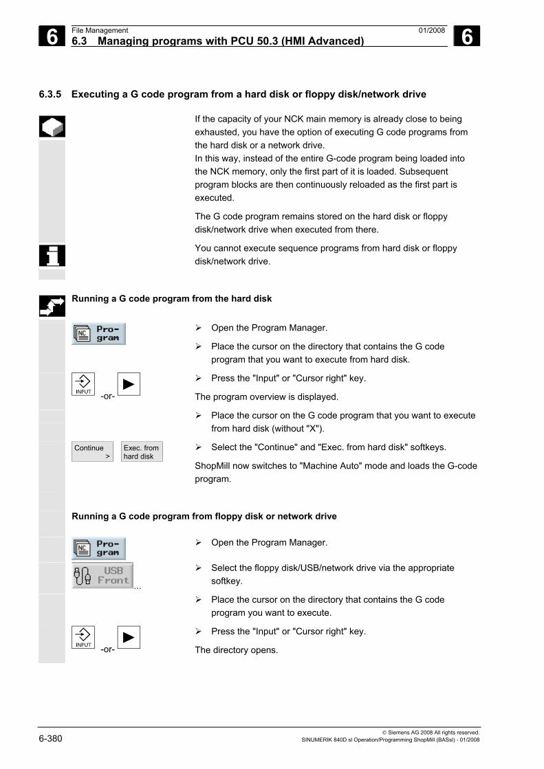
6 File Management 01/2008 6.3 Managing programs with PCU 50.3 (HMI Advanced)
6
© Siemens AG 2008 All rights reserved. 6-380 SINUMERIK 840D sl Operation/Programming ShopMill (BASsl) - 01/2008
6.3.5 Executing a G code program from a hard disk or floppy disk/network drive
If the capacity of your NCK main memory is already close to being exhausted, you have the option of executing G code programs from the hard disk or a network drive. In this way, instead of the entire G-code program being loaded into the NCK memory, only the first part of it is loaded. Subsequent program blocks are then continuously reloaded as the first part is executed.
The G code program remains stored on the hard disk or floppy disk/network drive when executed from there.
You cannot execute sequence programs from hard disk or floppy disk/network drive.
Running a G code program from the hard disk
Open the Program Manager.
Place the cursor on the directory that contains the G code program that you want to execute from hard disk.
-or-
Press the "Input" or "Cursor right" key.
The program overview is displayed.
Place the cursor on the G code program that you want to execute from hard disk (without "X").
Continue >
Exec. from hard disk
Select the "Continue" and "Exec. from hard disk" softkeys.
ShopMill now switches to "Machine Auto" mode and loads the G-code program.
Running a G code program from floppy disk or network drive
Open the Program Manager.
...
Select the floppy disk/USB/network drive via the appropriate softkey.
Place the cursor on the directory that contains the G code program you want to execute.
-or-
Press the "Input" or "Cursor right" key.
The directory opens.
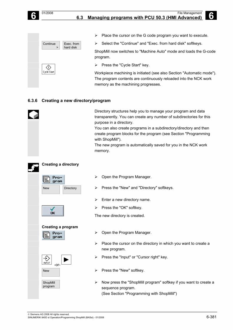
6 01/2008 File Management6.3 Managing programs with PCU 50.3 (HMI Advanced)
6
© Siemens AG 2008 All rights reserved. SINUMERIK 840D sl Operation/Programming ShopMill (BASsl) - 01/2008 6-381
Place the cursor on the G code program you want to execute.
Continue >
Exec. from hard disk
Select the "Continue" and "Exec. from hard disk" softkeys.
ShopMill now switches to "Machine Auto" mode and loads the G-code program.
Cycle Start
Press the "Cycle Start" key.
Workpiece machining is initiated (see also Section "Automatic mode"). The program contents are continuously reloaded into the NCK work memory as the machining progresses.
6.3.6 Creating a new directory/program
Directory structures help you to manage your program and data transparently. You can create any number of subdirectories for this purpose in a directory. You can also create programs in a subdirectory/directory and then create program blocks for the program (see Section "Programming with ShopMill"). The new program is automatically saved for you in the NCK work memory.
Creating a directory
Open the Program Manager.
New
Directory
Press the "New" and "Directory" softkeys.
Enter a new directory name.
Press the "OK" softkey.
The new directory is created.
Open the Program Manager.
Place the cursor on the directory in which you want to create a new program.
-or-
Press the "Input" or "Cursor right" key.
New
Press the "New" softkey.
ShopMillprogram
Now press the "ShopMill program" softkey if you want to create a sequence program. (See Section "Programming with ShopMill")
Creating a program
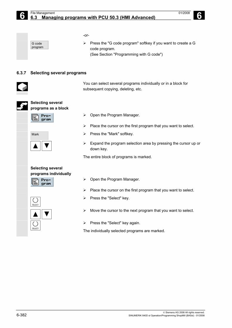
6 File Management 01/2008 6.3 Managing programs with PCU 50.3 (HMI Advanced)
6
© Siemens AG 2008 All rights reserved. 6-382 SINUMERIK 840D sl Operation/Programming ShopMill (BASsl) - 01/2008
-or-
G codeprogram
Press the "G code program" softkey if you want to create a G code program. (See Section "Programming with G code")
6.3.7 Selecting several programs
You can select several programs individually or in a block for subsequent copying, deleting, etc.
Selecting several
programs as a block
Open the Program Manager.
Place the cursor on the first program that you want to select.
Mark
Press the "Mark" softkey.
Expand the program selection area by pressing the cursor up or down key.
The entire block of programs is marked.
Selecting several programs individually
Open the Program Manager.
Place the cursor on the first program that you want to select.
Press the "Select" key.
Move the cursor to the next program that you want to select.
Press the "Select" key again.
The individually selected programs are marked.
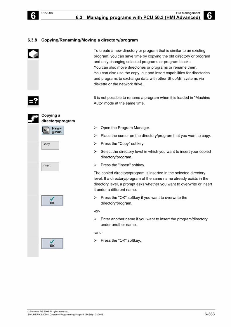
6 01/2008 File Management6.3 Managing programs with PCU 50.3 (HMI Advanced)
6
© Siemens AG 2008 All rights reserved. SINUMERIK 840D sl Operation/Programming ShopMill (BASsl) - 01/2008 6-383
6.3.8 Copying/Renaming/Moving a directory/program
To create a new directory or program that is similar to an existing program, you can save time by copying the old directory or program and only changing selected programs or program blocks. You can also move directories or programs or rename them. You can also use the copy, cut and insert capabilities for directories and programs to exchange data with other ShopMill systems via diskette or the network drive.
It is not possible to rename a program when it is loaded in "Machine
Auto" mode at the same time.
Copying a
directory/program
Open the Program Manager.
Place the cursor on the directory/program that you want to copy.
Copy
Press the "Copy" softkey.
Select the directory level in which you want to insert your copied directory/program.
Insert
Press the "Insert" softkey.
The copied directory/program is inserted in the selected directory level. If a directory/program of the same name already exists in the directory level, a prompt asks whether you want to overwrite or insert it under a different name.
Press the "OK" softkey if you want to overwrite the directory/program.
-or-
Enter another name if you want to insert the program/directory under another name.
-and-
Press the "OK" softkey.
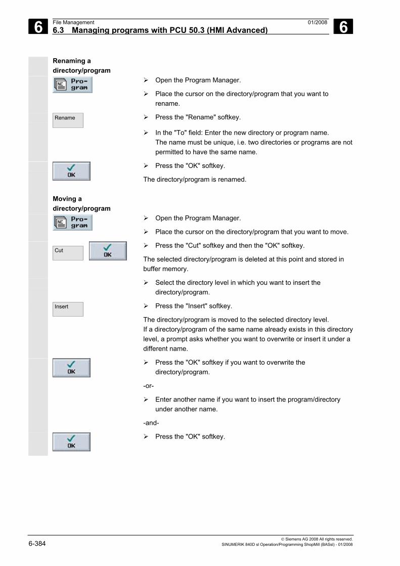
6 File Management 01/2008 6.3 Managing programs with PCU 50.3 (HMI Advanced)
6
© Siemens AG 2008 All rights reserved. 6-384 SINUMERIK 840D sl Operation/Programming ShopMill (BASsl) - 01/2008
Renaming a directory/program
Open the Program Manager.
Place the cursor on the directory/program that you want to rename.
Rename
Press the "Rename" softkey.
In the "To" field: Enter the new directory or program name. The name must be unique, i.e. two directories or programs are not permitted to have the same name.
Press the "OK" softkey.
The directory/program is renamed.
Moving a directory/program
Open the Program Manager.
Place the cursor on the directory/program that you want to move.
Cut
Press the "Cut" softkey and then the "OK" softkey.
The selected directory/program is deleted at this point and stored in buffer memory.
Select the directory level in which you want to insert the directory/program.
Insert
Press the "Insert" softkey.
The directory/program is moved to the selected directory level. If a directory/program of the same name already exists in this directorylevel, a prompt asks whether you want to overwrite or insert it under a different name.
Press the "OK" softkey if you want to overwrite the directory/program.
-or-
Enter another name if you want to insert the program/directory under another name.
-and-
Press the "OK" softkey.
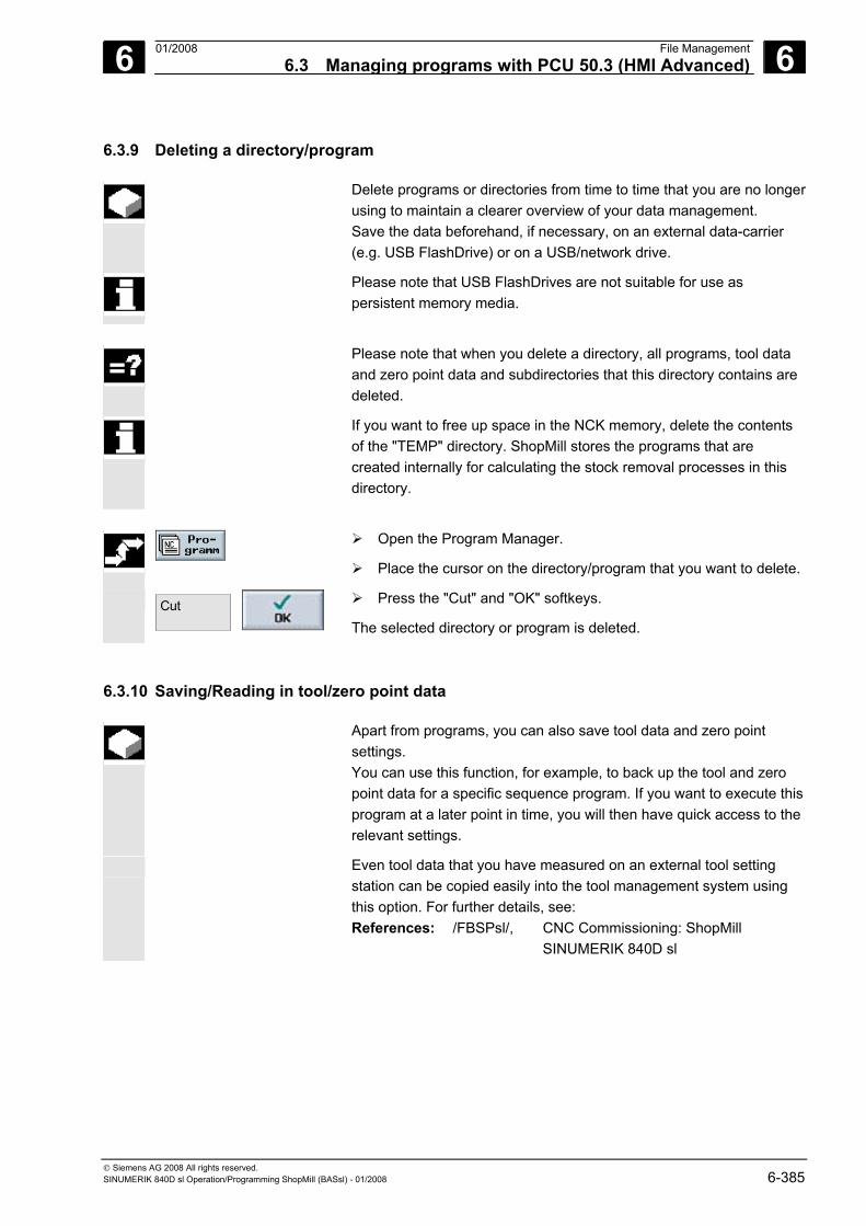
6 01/2008 File Management6.3 Managing programs with PCU 50.3 (HMI Advanced)
6
© Siemens AG 2008 All rights reserved. SINUMERIK 840D sl Operation/Programming ShopMill (BASsl) - 01/2008 6-385
6.3.9 Deleting a directory/program
Delete programs or directories from time to time that you are no longerusing to maintain a clearer overview of your data management. Save the data beforehand, if necessary, on an external data-carrier (e.g. USB FlashDrive) or on a USB/network drive.
Please note that USB FlashDrives are not suitable for use as persistent memory media.
Please note that when you delete a directory, all programs, tool data
and zero point data and subdirectories that this directory contains are deleted.
If you want to free up space in the NCK memory, delete the contents of the "TEMP" directory. ShopMill stores the programs that are created internally for calculating the stock removal processes in this directory.
Open the Program Manager.
Place the cursor on the directory/program that you want to delete.
Cut
Press the "Cut" and "OK" softkeys.
The selected directory or program is deleted.
6.3.10 Saving/Reading in tool/zero point data
Apart from programs, you can also save tool data and zero point settings. You can use this function, for example, to back up the tool and zero point data for a specific sequence program. If you want to execute this program at a later point in time, you will then have quick access to the relevant settings.
Even tool data that you have measured on an external tool setting station can be copied easily into the tool management system using this option. For further details, see: References: /FBSPsl/, CNC Commissioning: ShopMill SINUMERIK 840D sl
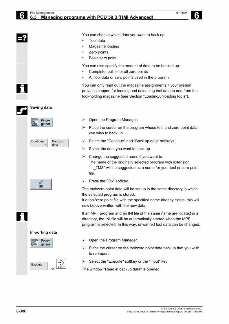
6 File Management 01/2008 6.3 Managing programs with PCU 50.3 (HMI Advanced)
6
© Siemens AG 2008 All rights reserved. 6-386 SINUMERIK 840D sl Operation/Programming ShopMill (BASsl) - 01/2008
You can choose which data you want to back up: • Tool data • Magazine loading • Zero points • Basic zero point
You can also specify the amount of data to be backed up: • Complete tool list or all zero points • All tool data or zero points used in the program
You can only read out the magazine assignments if your system provides support for loading and unloading tool data to and from the tool-holding magazine (see Section "Loading/unloading tools").
Saving data
Open the Program Manager.
Place the cursor on the program whose tool and zero point data you wish to back up.
Continue >
Back up data
Select the "Continue" and "Back up data" softkeys.
Select the data you want to back up.
Change the suggested name if you want to. The name of the originally selected program with extension "..._TMZ" will be suggested as a name for your tool or zero point file.
Press the "OK" softkey.
The tool/zero point data will be set up in the same directory in which the selected program is stored. If a tool/zero point file with the specified name already exists, this will now be overwritten with the new data.
If an MPF program and an INI file of the same name are located in a directory, the INI file will be automatically started when the MPF program is selected. In this way, unwanted tool data can be changed.
Importing data
Open the Program Manager.
Place the cursor on the tool/zero point data backup that you wish to re-import.
Execute
-or-
Select the "Execute" softkey or the "Input" key.
The window "Read in backup data" is opened.
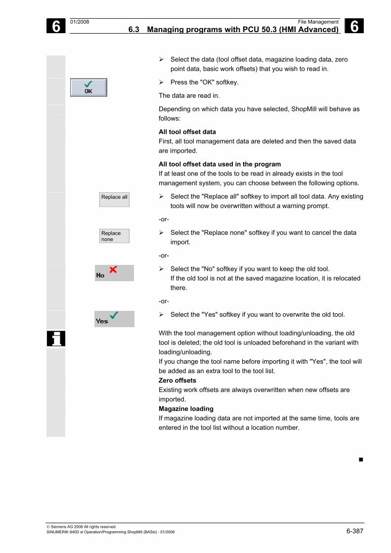
6 01/2008 File Management6.3 Managing programs with PCU 50.3 (HMI Advanced)
6
© Siemens AG 2008 All rights reserved. SINUMERIK 840D sl Operation/Programming ShopMill (BASsl) - 01/2008 6-387
Select the data (tool offset data, magazine loading data, zero point data, basic work offsets) that you wish to read in.
Press the "OK" softkey.
The data are read in.
Depending on which data you have selected, ShopMill will behave as follows:
All tool offset data First, all tool management data are deleted and then the saved data are imported.
All tool offset data used in the program If at least one of the tools to be read in already exists in the tool management system, you can choose between the following options.
Replace all
Select the "Replace all" softkey to import all tool data. Any existing tools will now be overwritten without a warning prompt.
-or-
Replacenone
Select the "Replace none" softkey if you want to cancel the data import.
-or-
Select the "No" softkey if you want to keep the old tool. If the old tool is not at the saved magazine location, it is relocated there.
-or-
Select the "Yes" softkey if you want to overwrite the old tool.
With the tool management option without loading/unloading, the old tool is deleted; the old tool is unloaded beforehand in the variant with loading/unloading. If you change the tool name before importing it with "Yes", the tool will be added as an extra tool to the tool list.
Zero offsets Existing work offsets are always overwritten when new offsets are imported.
Magazine loading If magazine loading data are not imported at the same time, tools are entered in the tool list without a location number.
6 File Management 01/2008 6.3 Managing programs with PCU 50.3 (HMI Advanced)
6
© Siemens AG 2008 All rights reserved. 6-388 SINUMERIK 840D sl Operation/Programming ShopMill (BASsl) - 01/2008
Notes
7 01/2008 Mold making 7
© Siemens AG 2008 All rights reserved. SINUMERIK 840D sl Operation/Programming ShopMill (BASsl) - 7-389
Mold making 7.1 Prerequisites ........................................................................................................... 7-390
7.2 Setting up the machine ........................................................................................... 7-392 7.2.1 Measuring a tool ..................................................................................................... 7-392
7.3 Creating a program ................................................................................................. 7-393 7.3.1 Creating a program ................................................................................................. 7-393 7.3.2 Programming a tool................................................................................................. 7-393 7.3.3 Programming the "High speed settings" cycle........................................................ 7-393 7.3.4 Calling a subroutine ................................................................................................ 7-394
7.4 Executing a program............................................................................................... 7-397 7.4.1 Selecting a program for execution .......................................................................... 7-397 7.4.2 Starting execution at a specific program point........................................................ 7-398
7.5 Example .................................................................................................................. 7-399
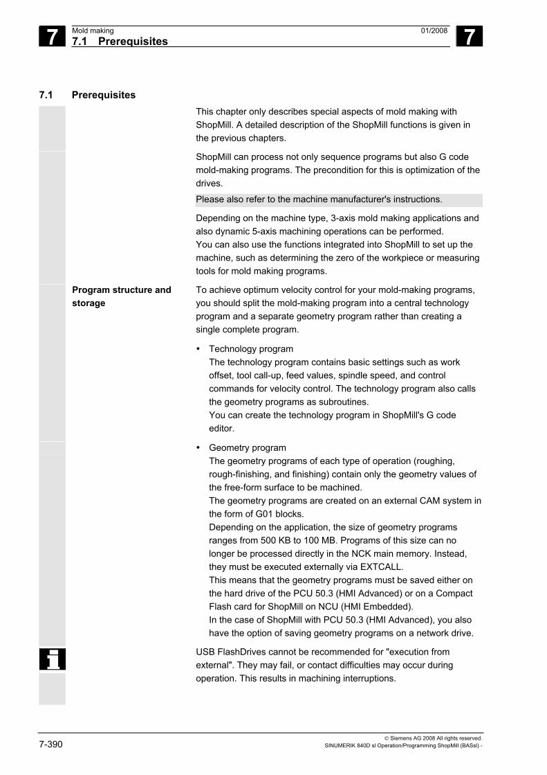
7 Mold making 01/2008 7.1 Prerequisites
7
© Siemens AG 2008 All rights reserved. 7-390 SINUMERIK 840D sl Operation/Programming ShopMill (BASsl) -
7.1 Prerequisites This chapter only describes special aspects of mold making with
ShopMill. A detailed description of the ShopMill functions is given in the previous chapters.
ShopMill can process not only sequence programs but also G code mold-making programs. The precondition for this is optimization of the drives.
Please also refer to the machine manufacturer's instructions.
Depending on the machine type, 3-axis mold making applications and also dynamic 5-axis machining operations can be performed. You can also use the functions integrated into ShopMill to set up the machine, such as determining the zero of the workpiece or measuring tools for mold making programs.
Program structure and storage
To achieve optimum velocity control for your mold-making programs, you should split the mold-making program into a central technology program and a separate geometry program rather than creating a single complete program.
• Technology program The technology program contains basic settings such as work offset, tool call-up, feed values, spindle speed, and control commands for velocity control. The technology program also calls the geometry programs as subroutines. You can create the technology program in ShopMill's G code editor.
• Geometry program The geometry programs of each type of operation (roughing, rough-finishing, and finishing) contain only the geometry values of the free-form surface to be machined. The geometry programs are created on an external CAM system in the form of G01 blocks. Depending on the application, the size of geometry programs ranges from 500 KB to 100 MB. Programs of this size can no longer be processed directly in the NCK main memory. Instead, they must be executed externally via EXTCALL. This means that the geometry programs must be saved either on the hard drive of the PCU 50.3 (HMI Advanced) or on a Compact Flash card for ShopMill on NCU (HMI Embedded). In the case of ShopMill with PCU 50.3 (HMI Advanced), you also have the option of saving geometry programs on a network drive.
USB FlashDrives cannot be recommended for "execution from external". They may fail, or contact difficulties may occur during operation. This results in machining interruptions.
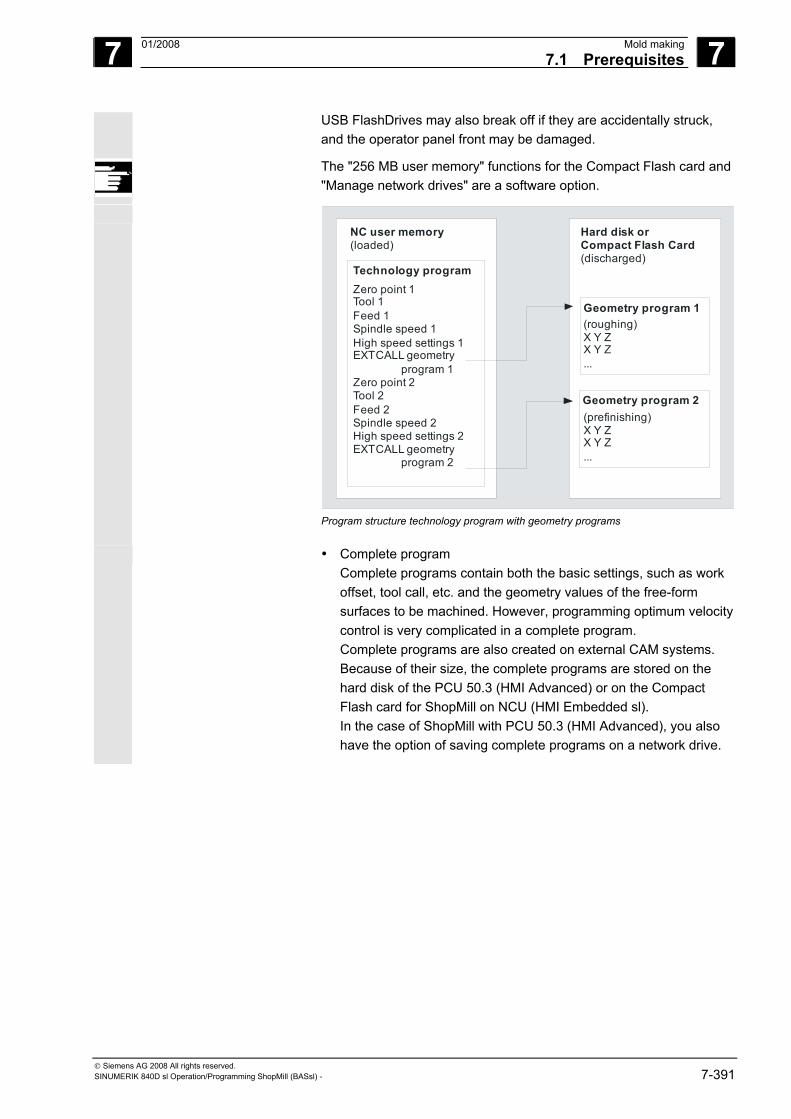
7 01/2008 Mold making7.1 Prerequisites
7
© Siemens AG 2008 All rights reserved. SINUMERIK 840D sl Operation/Programming ShopMill (BASsl) - 7-391
USB FlashDrives may also break off if they are accidentally struck, and the operator panel front may be damaged.
The "256 MB user memory" functions for the Compact Flash card and "Manage network drives" are a software option.
NC user memory(loaded)
Technology programZero point 1Tool 1Feed 1Spindle speed 1High speed settings 1EXTCALL geometry program 1Zero point 2Tool 2Feed 2Spindle speed 2High speed settings 2EXTCALL geometry program 2
Hard disk orCompact Flash Card(discharged)
Geometry program 1(roughing)X Y ZX Y Z...
Geometry program 2(prefinishing)X Y ZX Y Z...
Program structure technology program with geometry programs
• Complete program Complete programs contain both the basic settings, such as work offset, tool call, etc. and the geometry values of the free-form surfaces to be machined. However, programming optimum velocity control is very complicated in a complete program. Complete programs are also created on external CAM systems. Because of their size, the complete programs are stored on the hard disk of the PCU 50.3 (HMI Advanced) or on the Compact Flash card for ShopMill on NCU (HMI Embedded sl). In the case of ShopMill with PCU 50.3 (HMI Advanced), you also have the option of saving complete programs on a network drive.
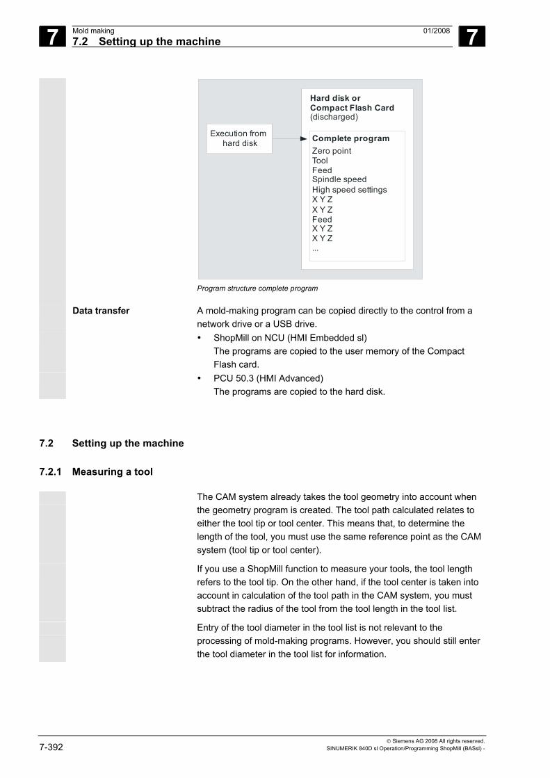
7 Mold making 01/2008 7.2 Setting up the machine
7
© Siemens AG 2008 All rights reserved. 7-392 SINUMERIK 840D sl Operation/Programming ShopMill (BASsl) -
Execution from hard disk
Hard disk orCompact Flash Card(discharged)
Complete programZero pointToolFeedSpindle speedHigh speed settingsX Y ZX Y ZFeedX Y ZX Y Z...
Program structure complete program
Data transfer A mold-making program can be copied directly to the control from a network drive or a USB drive.
• ShopMill on NCU (HMI Embedded sl) The programs are copied to the user memory of the Compact Flash card.
• PCU 50.3 (HMI Advanced) The programs are copied to the hard disk.
7.2 Setting up the machine
7.2.1 Measuring a tool
The CAM system already takes the tool geometry into account when the geometry program is created. The tool path calculated relates to either the tool tip or tool center. This means that, to determine the length of the tool, you must use the same reference point as the CAM system (tool tip or tool center).
If you use a ShopMill function to measure your tools, the tool length refers to the tool tip. On the other hand, if the tool center is taken into account in calculation of the tool path in the CAM system, you must subtract the radius of the tool from the tool length in the tool list.
Entry of the tool diameter in the tool list is not relevant to the processing of mold-making programs. However, you should still enter the tool diameter in the tool list for information.
7 01/2008 Mold making7.3 Creating a program
7
© Siemens AG 2008 All rights reserved. SINUMERIK 840D sl Operation/Programming ShopMill (BASsl) - 7-393
7.3 Creating a program
7.3.1 Creating a program
For the technology program, you create a new G code program in the program manager and then process it in the G code editor. A sequence program is not suitable for use as a technology program.
The geometry program or complete program is created on an external CAM system. For example, if you subsequently want to insert comments into the geometry program or change the tool name in the complete program, this can be done in ShopMill's G code editor.
7.3.2 Programming a tool
If you program a tool in the technology program, please note the following: The geometry of the programmed tool must match the tool geometry used by the CAM system when the geometry program was created.
7.3.3 Programming the "High speed settings" cycle
Machining of free-form surfaces involves high velocity, precision, and surface quality requirements . You can achieve optimum velocity control depending on the type of processing (roughing, rough-finishing, finishing) very simply with the "High Speed Settings" cycle.
You can call the cycle via the cycle support in the G code editor. The output tolerance of the postprocessor of the CAM system is usually entered in the "Tolerance" parameter.
Program the cycle before the geometry program call in the technology program. More information on the cycle can be found in: References: /PGZ/, Programming Manual Cycles SINUMERIK 840D sl/840D/840Di
7 Mold making 01/2008 7.3 Creating a program
7
© Siemens AG 2008 All rights reserved. 7-394 SINUMERIK 840D sl Operation/Programming ShopMill (BASsl) -
7.3.4 Calling a subroutine
The geometry program is called from the technology program as a subroutine. Because the geometry programs are not stored in the NCK work memory but on the hard disk of the PCU 50.3 (HMI Advanced), or on the Compact Flash card for ShopMill on NCU (HMI Embedded sl), you only have to call the subroutine with the "EXTCALL" command.
To execute programs on the HMI user memory of the CF card, you require an option.
PCU 50.3 (HMI-Advanced)
The technology program and the geometry programs are in the same directory as the hard disk. The program is called with EXTCALL "MYGEOPROG". For detailed information refer to: References: /BAD/, Operating Manual HMI Advanced SINUMERIK 840D sl/840D/840Di
ShopMill on NCU (HMI Embedded sl)
The technology program is stored in the NCK main memory. The HMI user memory on the CompactFlash card of the NCU is available for the purpose of storing the geometry program.
If the EXTCALL command is used to call a geometry subroutine in a technology program, the control searches for this subroutine in the possible storage locations in a certain order. If the called program is not found in a storage location, the next storage location is searched in accordance with the search order.
The search follows the following search order and is ended as soon asthe called program is found.
1. Search in the storage location specified via SD 42700 SC_EXT_PROG_PATH, provided a path is specified.
2. Search in the HMI user memory of the CF card.
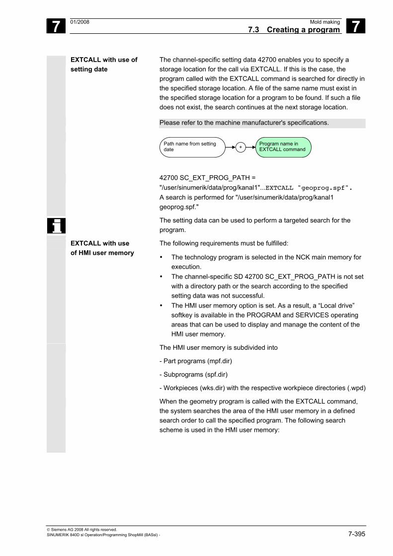
7 01/2008 Mold making7.3 Creating a program
7
© Siemens AG 2008 All rights reserved. SINUMERIK 840D sl Operation/Programming ShopMill (BASsl) - 7-395
EXTCALL with use of setting date
The channel-specific setting data 42700 enables you to specify a storage location for the call via EXTCALL. If this is the case, the program called with the EXTCALL command is searched for directly in the specified storage location. A file of the same name must exist in the specified storage location for a program to be found. If such a file does not exist, the search continues at the next storage location.
Please refer to the machine manufacturer's specifications.
Path name from setting date +
Program name in EXTCALL command
42700 SC_EXT_PROG_PATH = "/user/sinumerik/data/prog/kanal1"...EXTCALL "geoprog.spf". A search is performed for "/user/sinumerik/data/prog/kanal1 geoprog.spf."
The setting data can be used to perform a targeted search for the program.
EXTCALL with use of HMI user memory
The following requirements must be fulfilled:
• The technology program is selected in the NCK main memory for execution.
• The channel-specific SD 42700 SC_EXT_PROG_PATH is not set with a directory path or the search according to the specified setting data was not successful.
• The HMI user memory option is set. As a result, a “Local drive” softkey is available in the PROGRAM and SERVICES operating areas that can be used to display and manage the content of the HMI user memory.
The HMI user memory is subdivided into
- Part programs (mpf.dir)
- Subprograms (spf.dir)
- Workpieces (wks.dir) with the respective workpiece directories (.wpd)
When the geometry program is called with the EXTCALL command, the system searches the area of the HMI user memory in a defined search order to call the specified program. The following search scheme is used in the HMI user memory:
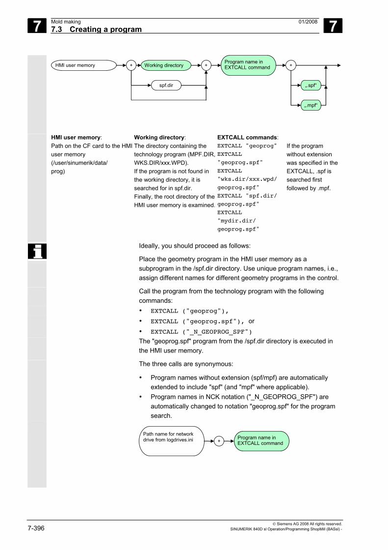
7 Mold making 01/2008 7.3 Creating a program
7
© Siemens AG 2008 All rights reserved. 7-396 SINUMERIK 840D sl Operation/Programming ShopMill (BASsl) -
HMI user memory + Working directory
spf.dir
+Program name in EXTCALL command +
„.spf“
„.mpf“
HMI user memory: Path on the CF card to the HMI user memory (/user/sinumerik/data/ prog)
Working directory: The directory containing the technology program (MPF.DIR, WKS.DIR/xxx.WPD). If the program is not found in the working directory, it is searched for in spf.dir. Finally, the root directory of the HMI user memory is examined.
EXTCALL commands: EXTCALL "geoprog" EXTCALL
"geoprog.spf" EXTCALL
"wks.dir/xxx.wpd/
geoprog.spf"
EXTCALL "spf.dir/
geoprog.spf" EXTCALL
"mydir.dir/
geoprog.spf"
If the program without extension was specified in the EXTCALL, .spf is searched first followed by .mpf.
Ideally, you should proceed as follows:
Place the geometry program in the HMI user memory as a subprogram in the /spf.dir directory. Use unique program names, i.e., assign different names for different geometry programs in the control.
Call the program from the technology program with the following commands:
• EXTCALL ("geoprog"), • EXTCALL ("geoprog.spf"), or • EXTCALL ("_N_GEOPROG_SPF")
The "geoprog.spf" program from the /spf.dir directory is executed in the HMI user memory.
The three calls are synonymous:
• Program names without extension (spf/mpf) are automatically extended to include "spf" (and "mpf" where applicable).
• Program names in NCK notation ("_N_GEOPROG_SPF") are automatically changed to notation "geoprog.spf" for the program search.
Path name for network drive from logdrives.ini
+Program name in EXTCALL command
7 01/2008 Mold making7.4 Executing a program
7
© Siemens AG 2008 All rights reserved. SINUMERIK 840D sl Operation/Programming ShopMill (BASsl) - 7-397
EXTCALL with targeted call In addition to use of the search mechanism described above, you can also call a specific subroutine with the EXTCALL command by indicating the storage location of the subroutine in the EXTCALL command.
Examples HMI user memory: EXTCALL ("/user/sinumerik/data/prog/spf.dir
/myextsub.spf")
The "myextsub.spf" program stored in the /spf.dir directory in the HMI user memory is called. EXTCALL ("/user/sinumerik/data/prog/wpd.dir/
mywpd.dir/myextsub.spf")
The "myextsub.spf" program stored in the "mywpd.dir" workpiece in the /wks.dir workpiece directory in the HMI user memory is called. EXTCALL ("/user/sinumerik/data/prog/mydir.dir/
myextsub.spf")
The "myextsub.spf" program stored in your /mydir.dir directory in the HMI user memory is called.
7.4 Executing a program
7.4.1 Selecting a program for execution
The technology program that is located in the NCK main memory is selected for execution just like a normal G code program. The geometry program is then automatically selected via the "EXTCALL" command.
A complete program, which is located either on the hard disk or the PCU 50.3 (HMI Advanced) or on the Compact Flash card for ShopMill on NCU (HMI Embedded sl) or on a USB/network drive, is selected with the "Execute HD" softkey in the program manager.
7 Mold making 01/2008 7.4 Executing a program
7
© Siemens AG 2008 All rights reserved. 7-398 SINUMERIK 840D sl Operation/Programming ShopMill (BASsl) -
7.4.2 Starting execution at a specific program point
Technology program with geometry programs
To start execution of a certain program section in a geometry program, enter the destination in the search pointer. Level 1 (technology program): Program line with required geometry program call Level 2 (geometry program): Program line for starting machining
If the geometry program is on the compact flash card, you must not only specify the program name in the "Program" input field on level 2 but also the path.
Select the accelerated calculation method "External – without calculation". The block search is performed in the technology program with calculation. All EXTCALL commands before the required geometry program are skipped. The block search in the required geometry program is performed without calculation.
This calculation method assumes that all machine functions, such as tool call, machining feedrate, spindle speed, etc. are contained in the technology program. The geometry program must only contain geometry values for the free-form surface.
Complete program To start execution of a certain program section in a complete program, place the cursor directly on the required destination block (using "Search", if necessary).
When you then select a calculation method, consider: The "External without calculation" method performs a search without considering the machine functions. That means execution of the program can only be started a points at which all relevant machine functions, such as feed, spindle speed, etc. are performed. For safety reasons, you should therefore choose the "to contour" or "to end point" method. However, these calculation methods require more computation time.
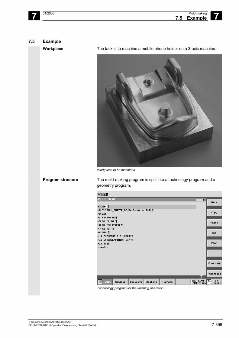
7 01/2008 Mold making7.5 Example
7
© Siemens AG 2008 All rights reserved. SINUMERIK 840D sl Operation/Programming ShopMill (BASsl) - 7-399
7.5 Example Workpiece The task is to machine a mobile phone holder on a 3-axis machine.
Workpiece to be machined
Program structure The mold-making program is split into a technology program and a geometry program.
Technology program for the finishing operation
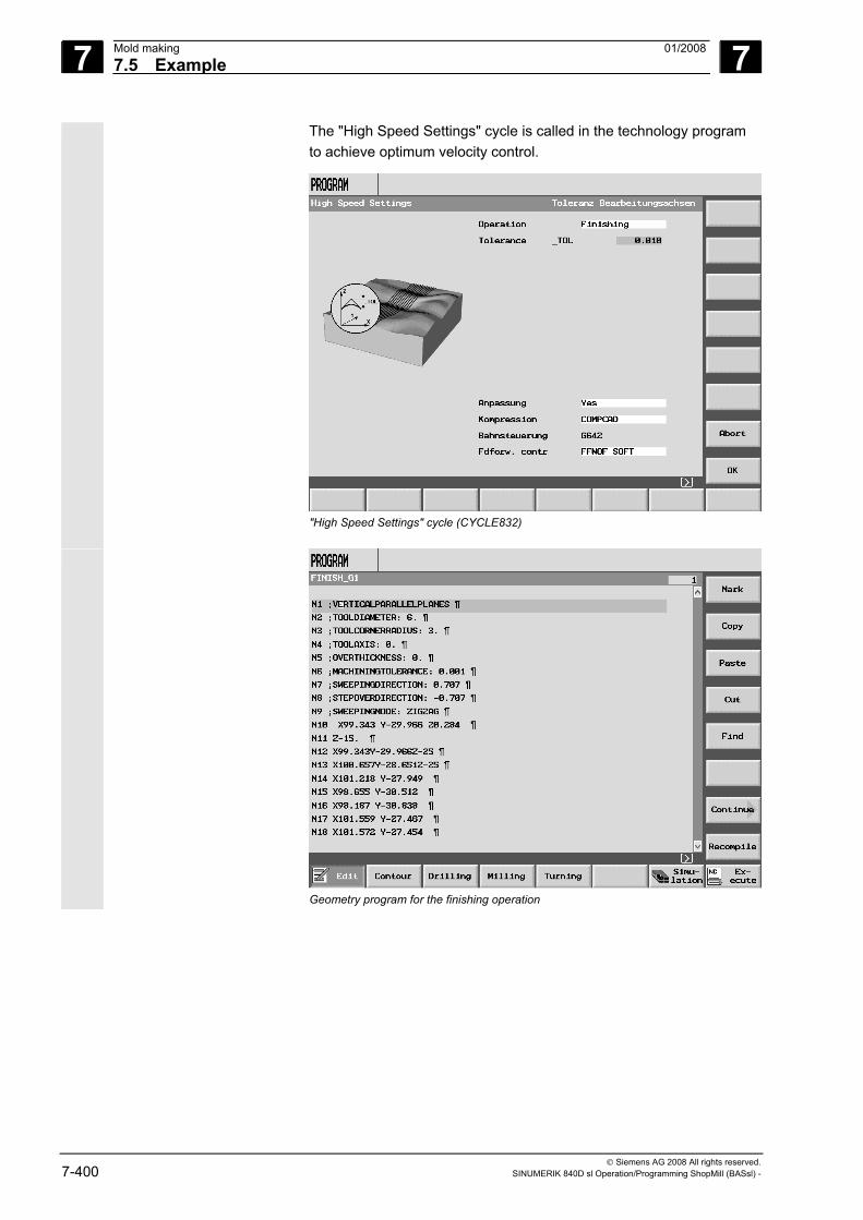
7 Mold making 01/2008 7.5 Example
7
© Siemens AG 2008 All rights reserved. 7-400 SINUMERIK 840D sl Operation/Programming ShopMill (BASsl) -
The "High Speed Settings" cycle is called in the technology program to achieve optimum velocity control.
"High Speed Settings" cycle (CYCLE832)
Geometry program for the finishing operation
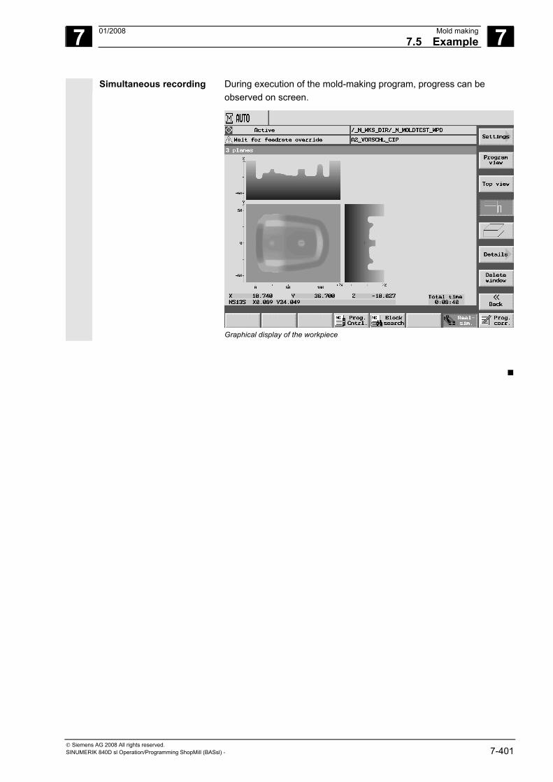
7 01/2008 Mold making7.5 Example
7
© Siemens AG 2008 All rights reserved. SINUMERIK 840D sl Operation/Programming ShopMill (BASsl) - 7-401
Simultaneous recording During execution of the mold-making program, progress can be observed on screen.
Graphical display of the workpiece
7 Mold making 01/2008 7.5 Example
7
© Siemens AG 2008 All rights reserved. 7-402 SINUMERIK 840D sl Operation/Programming ShopMill (BASsl) -
Notes
8 01/2008 Interrupts and messages 8
© Siemens AG 2008 All rights reserved. SINUMERIK 840D sl Operation/Programming ShopMill (BASsl) - 01/2008 8-403
Interrupts and messages 8.1 Messages................................................................................................................ 8-404
8.2 Alarms ..................................................................................................................... 8-404
8.3 User data................................................................................................................. 8-405
8.4 Version display........................................................................................................ 8-407
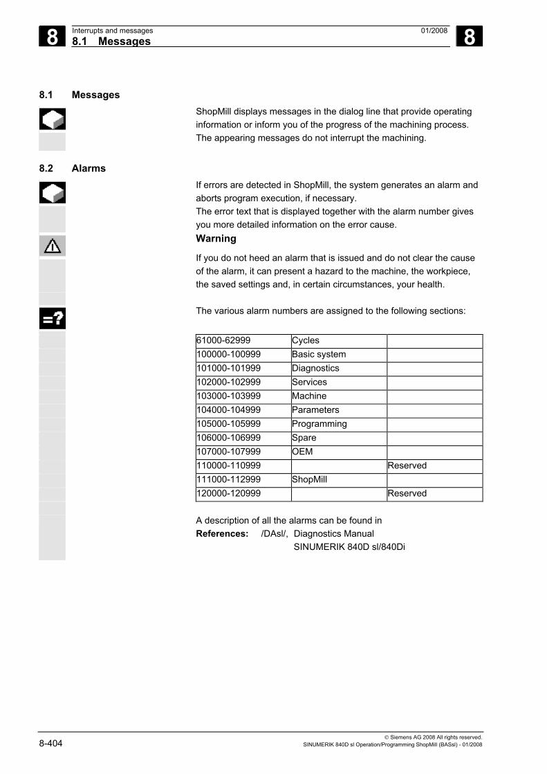
8 Interrupts and messages 01/2008 8.1 Messages
8
© Siemens AG 2008 All rights reserved. 8-404 SINUMERIK 840D sl Operation/Programming ShopMill (BASsl) - 01/2008
8.1 Messages ShopMill displays messages in the dialog line that provide operating
information or inform you of the progress of the machining process. The appearing messages do not interrupt the machining.
8.2 Alarms If errors are detected in ShopMill, the system generates an alarm and
aborts program execution, if necessary. The error text that is displayed together with the alarm number gives you more detailed information on the error cause.
Warning
If you do not heed an alarm that is issued and do not clear the cause of the alarm, it can present a hazard to the machine, the workpiece, the saved settings and, in certain circumstances, your health.
The various alarm numbers are assigned to the following sections:
61000-62999 Cycles 100000-100999 Basic system 101000-101999 Diagnostics 102000-102999 Services 103000-103999 Machine 104000-104999 Parameters 105000-105999 Programming 106000-106999 Spare 107000-107999 OEM 110000-110999 Reserved 111000-112999 ShopMill 120000-120999 Reserved A description of all the alarms can be found in
References: /DAsl/, Diagnostics Manual SINUMERIK 840D sl/840Di
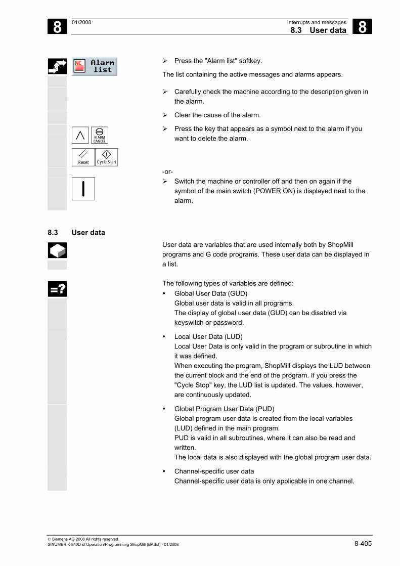
8 01/2008 Interrupts and messages8.3 User data
8
© Siemens AG 2008 All rights reserved. SINUMERIK 840D sl Operation/Programming ShopMill (BASsl) - 01/2008 8-405
Press the "Alarm list" softkey.
The list containing the active messages and alarms appears.
Carefully check the machine according to the description given in the alarm.
Clear the cause of the alarm.
Reset Cycle Start
Press the key that appears as a symbol next to the alarm if you want to delete the alarm.
-or-
Switch the machine or controller off and then on again if the symbol of the main switch (POWER ON) is displayed next to the alarm.
8.3 User data User data are variables that are used internally both by ShopMill
programs and G code programs. These user data can be displayed in a list.
The following types of variables are defined:
• Global User Data (GUD) Global user data is valid in all programs. The display of global user data (GUD) can be disabled via keyswitch or password.
• Local User Data (LUD)
Local User Data is only valid in the program or subroutine in which it was defined. When executing the program, ShopMill displays the LUD between the current block and the end of the program. If you press the "Cycle Stop" key, the LUD list is updated. The values, however, are continuously updated.
• Global Program User Data (PUD) Global program user data is created from the local variables (LUD) defined in the main program. PUD is valid in all subroutines, where it can also be read and written. The local data is also displayed with the global program user data.
• Channel-specific user data Channel-specific user data is only applicable in one channel.
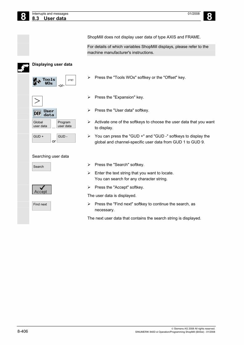
8 Interrupts and messages 01/2008 8.3 User data
8
© Siemens AG 2008 All rights reserved. 8-406 SINUMERIK 840D sl Operation/Programming ShopMill (BASsl) - 01/2008
ShopMill does not display user data of type AXIS and FRAME.
For details of which variables ShopMill displays, please refer to the machine manufacturer's instructions.
Displaying user data
-or-
Press the "Tools WOs" softkey or the "Offset" key.
Press the "Expansion" key.
Press the "User data" softkey.
Globaluser data ...
Programuser data
Activate one of the softkeys to choose the user data that you want to display.
GUD + or
GUD -
You can press the "GUD +" and "GUD -" softkeys to display the global and channel-specific user data from GUD 1 to GUD 9.
Searching user data
Search
Press the "Search" softkey.
Enter the text string that you want to locate. You can search for any character string.
Press the "Accept" softkey.
The user data is displayed.
Find next
Press the "Find next" softkey to continue the search, as necessary.
The next user data that contains the search string is displayed.
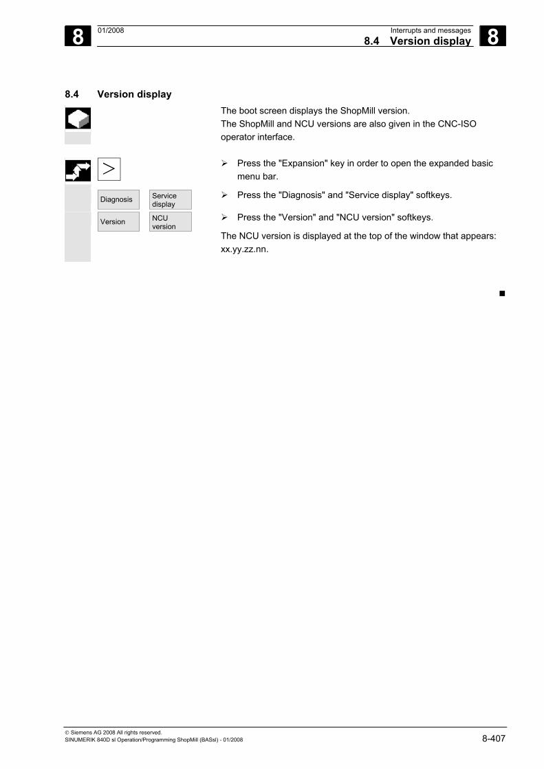
8 01/2008 Interrupts and messages8.4 Version display
8
© Siemens AG 2008 All rights reserved. SINUMERIK 840D sl Operation/Programming ShopMill (BASsl) - 01/2008 8-407
8.4 Version display The boot screen displays the ShopMill version.
The ShopMill and NCU versions are also given in the CNC-ISO operator interface.
Press the "Expansion" key in order to open the expanded basic menu bar.
Diagnosis
Servicedisplay
Press the "Diagnosis" and "Service display" softkeys.
Version
NCUversion
Press the "Version" and "NCU version" softkeys.
The NCU version is displayed at the top of the window that appears: xx.yy.zz.nn.
8 Interrupts and messages 01/2008 8.4 Version display
8
© Siemens AG 2008 All rights reserved. 8-408 SINUMERIK 840D sl Operation/Programming ShopMill (BASsl) - 01/2008
Notes
9 01/2008 Examples 9
© Siemens AG 2008 All rights reserved. SINUMERIK 840D sl Operation/Programming ShopMill (BASsl) - 01/2008 9-409
Examples 9.1 Example 1: Machining with rectangular/circular pocket and circumferential slot ... 9-410
9.2 Example 2: Translation and mirroring of a contour................................................. 9-418
9.3 Example 3: Cylinder surface transformation........................................................... 9-421
9.4 Example 4: Slot side compensation........................................................................ 9-425
9.5 Example 5: Swiveling.............................................................................................. 9-429
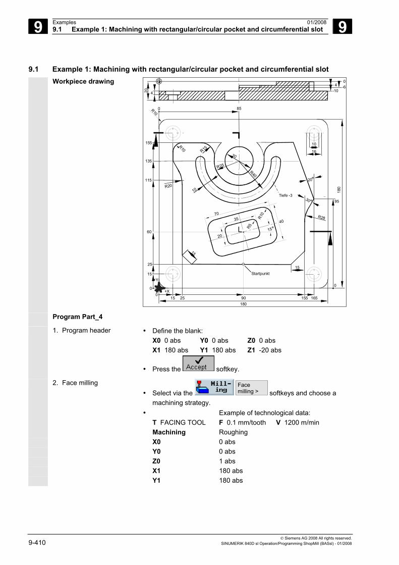
9 Examples 01/2008 9.1 Example 1: Machining with rectangular/circular pocket and circumferential slot
9
© Siemens AG 2008 All rights reserved. 9-410 SINUMERIK 840D sl Operation/Programming ShopMill (BASsl) - 01/2008
9.1 Example 1: Machining with rectangular/circular pocket and circumferential slot Workpiece drawing
R10
R10
R5
20
3570
40
15o
Startpunkt
30
R10
15
20o
R28
30 o
R40
R25
15
R20
Tiefe -3
R15
10
42016
10
0
95
180
0+X
+Y15
25
60
115
135
155
850
- 4-10
0-6
015 25 90 155 165
180
Program Part_4
1. Program header • Define the blank: X0 0 abs Y0 0 abs Z0 0 abs X1 180 abs Y1 180 abs Z1 -20 abs
• Press the softkey.
2. Face milling • Select via the
Face milling > softkeys and choose a
machining strategy. • Example of technological data:
T FACING TOOL F 0.1 mm/tooth V 1200 m/min Machining Roughing X0 0 abs Y0 0 abs Z0 1 abs X1 180 abs Y1 180 abs
9 01/2008 Examples9.1 Example 1: Machining with rectangular/circular pocket and circumferential slot
9
© Siemens AG 2008 All rights reserved. SINUMERIK 840D sl Operation/Programming ShopMill (BASsl) - 01/2008 9-411
Z1 0 abs DXY 80% DZ 0.5 UZ 0
• Press the softkey.
3. Outside contour of workpiece
The outside contour can be defined as a rectangular spigot as shown here. It is, of course, also possible to use the contour milling function.
• Select via the
Pocket >
Rectang.pocket softkeys
• Assign technological parameters T, F and S accordingly and enter the following parameters:
Position of reference point
Bottom left
Machining
Type of position Single position X0 0 abs Y0 0 abs Z0 0 abs W 180 abs L 180 abs R 10 abs α0 0 degrees Z1 20 inc DZ 20 UXY 0 UZ 0 W1 185 (fictitious blank dimension) L1 185 (fictitious blank dimension)
• Press the softkey.
4. Outside contour of island To machine the entire surface outside the island, define a contour pocket around the blank and then program the island. In this way, the entire surface area is machined and no residual material is left behind.
a) Outside contour of pocket • Select via the
New contour > softkeys
• Enter the contour name (here: Part_4_pocket) and confirm
• Fill out the start screen form for the contour Tool axis Z X -20 abs Y 0 abs
and confirm with .
9 Examples 01/2008 9.1 Example 1: Machining with rectangular/circular pocket and circumferential slot
9
© Siemens AG 2008 All rights reserved. 9-412 SINUMERIK 840D sl Operation/Programming ShopMill (BASsl) - 01/2008
• Enter the following contour elements and confirm each one by
pressing the softkey:
1. X 200 abs
2. Y 200 abs
3. X -20 abs
4.
Close contour
• Press the softkey.
a) Outside contour of island • Select via the
Newcontour > softkeys
• Enter the contour name (here: Part_4_Island) and confirm
• Fill out the start screen form for the contour Tool axis Z X 90 abs Y 25 abs
and confirm with .
• Enter the following contour elements and confirm each one by
pressing the softkey:
1. X 25 abs FS 15
2. Y 115 abs R 20
3. X 15 abs Y 135 abs
4. Y 155 abs R 10
5. X 60 abs R 15
6. Y 135 abs R 20
7.
Tangent toprec. elem. Direction of rotation
R 25 X 110 abs
8. Tangent toprec. elem.
Y 155 abs R 15
9. R 0
10. X 165 abs Y 95 abs α1 290 deg. R 0
11. X 155 abs α1 240 deg. R 28
12. FS 0
9 01/2008 Examples9.1 Example 1: Machining with rectangular/circular pocket and circumferential slot
9
© Siemens AG 2008 All rights reserved. SINUMERIK 840D sl Operation/Programming ShopMill (BASsl) - 01/2008 9-413
13. X 140 abs Y 25 abs α1 225 deg. R 0
14.
Close contour
c) Mill/solid machine a contour • Select via the
Solid > softkeys
• Assign technological parameters T, F and S accordingly (e.g. cutter diameter 10) and enter the following parameters:
Machining
Z0 0 abs Z1 10 inc DXY 4.5 mm DZ 10 UXY 0 mm UZ 0 Starting point Auto Insertion Center FZ 0.1 mm/tooth Retraction mode Select the mode, e.g. to retraction plane
•
Notes: • When selecting the milling tool, please make sure that the tool
diameter is large enough to cut the intended pocket. A message will be displayed if you make a mistake.
• If you want to finish cut the pocket, you must assign parameters UXY and UZ accordingly and add a second solid machining cycle for finishing.
5. Mill a rectangular pocket (large) • Select via the
Pocket >
Rectang. pocket softkeys
• Example of technological data: T MILL10 F 0.1 mm/tooth V 200 m/min
Position of reference point
Center
Machining
Type of position Single position X0 90 abs Y0 60 abs Z0 0 abs W 40 L 70 R 10 α0 15 Z1 4 inc DXY 4.5 mm
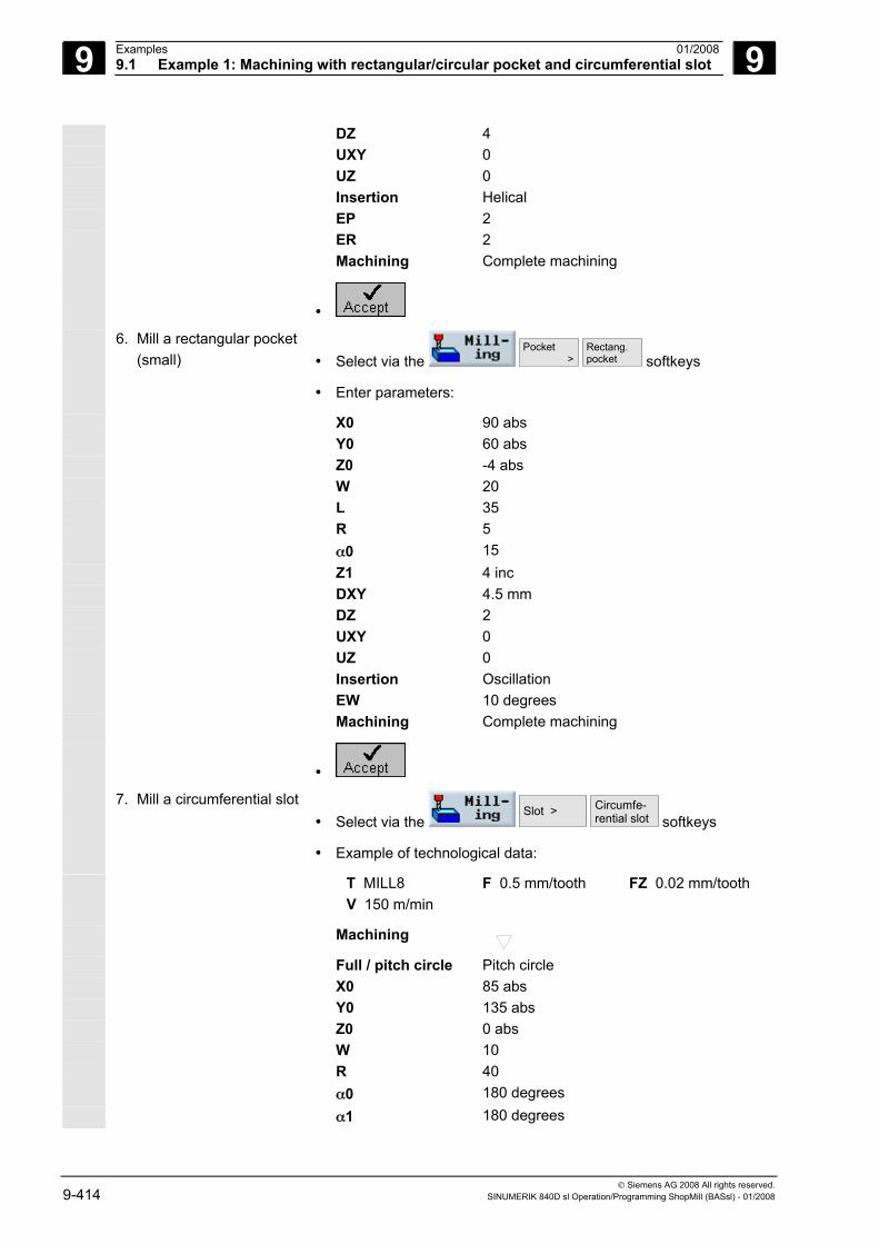
9 Examples 01/2008 9.1 Example 1: Machining with rectangular/circular pocket and circumferential slot
9
© Siemens AG 2008 All rights reserved. 9-414 SINUMERIK 840D sl Operation/Programming ShopMill (BASsl) - 01/2008
DZ 4 UXY 0 UZ 0 Insertion Helical EP 2 ER 2 Machining Complete machining
•
6. Mill a rectangular pocket (small) • Select via the
Pocket >
Rectang. pocket softkeys
• Enter parameters:
X0 90 abs Y0 60 abs Z0 -4 abs W 20 L 35 R 5 α0 15 Z1 4 inc DXY 4.5 mm DZ 2 UXY 0 UZ 0 Insertion Oscillation EW 10 degrees Machining Complete machining
•
7. Mill a circumferential slot • Select via the
Slot >
Circumfe-rential slot softkeys
• Example of technological data:
T MILL8 F 0.5 mm/tooth FZ 0.02 mm/tooth V 150 m/min
Machining
Full / pitch circle Pitch circle X0 85 abs Y0 135 abs Z0 0 abs W 10 R 40 α0 180 degrees α1 180 degrees
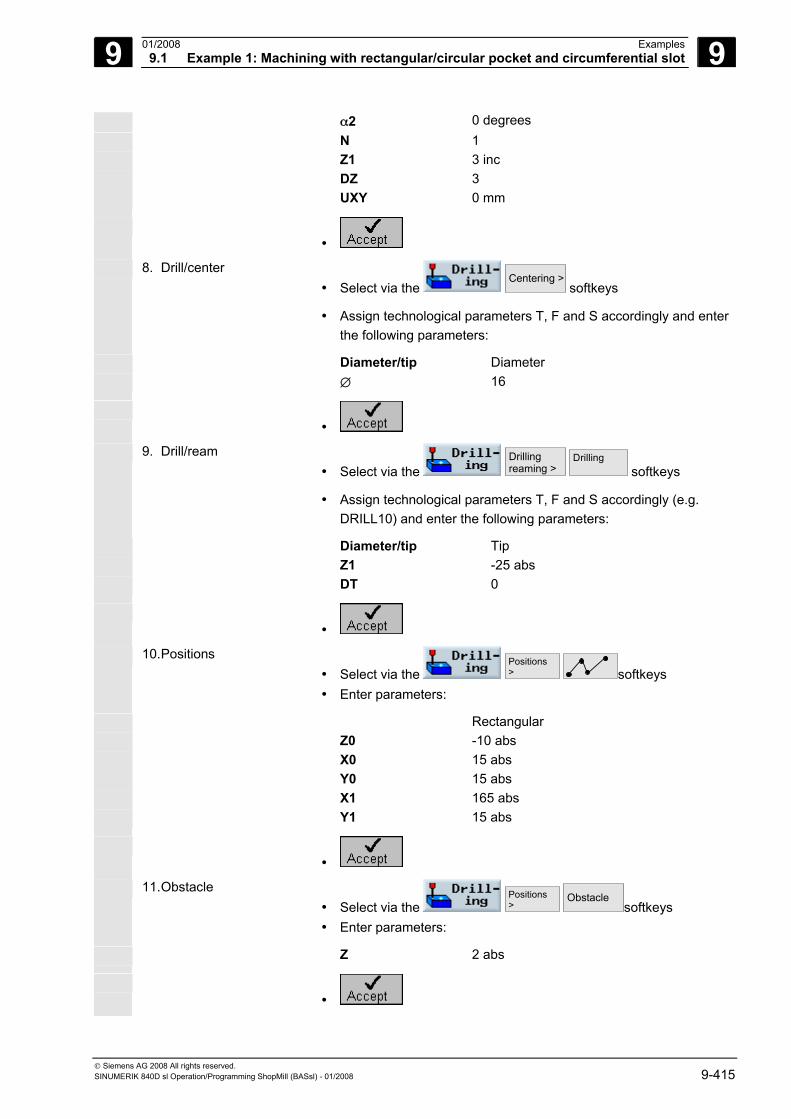
9 01/2008 Examples9.1 Example 1: Machining with rectangular/circular pocket and circumferential slot
9
© Siemens AG 2008 All rights reserved. SINUMERIK 840D sl Operation/Programming ShopMill (BASsl) - 01/2008 9-415
α2 0 degrees N 1 Z1 3 inc DZ 3 UXY 0 mm
•
8. Drill/center • Select via the
Centering > softkeys
• Assign technological parameters T, F and S accordingly and enter the following parameters:
Diameter/tip Diameter ∅ 16
•
9. Drill/ream • Select via the
Drilling reaming >
Drilling softkeys
• Assign technological parameters T, F and S accordingly (e.g. DRILL10) and enter the following parameters:
Diameter/tip Tip Z1 -25 abs DT 0
•
10. Positions • Select via the
Positions >
softkeys
• Enter parameters:
Rectangular Z0 -10 abs X0 15 abs Y0 15 abs X1 165 abs Y1 15 abs
•
11. Obstacle • Select via the
Positions >
Obstacle softkeys
• Enter parameters:
Z 2 abs
•
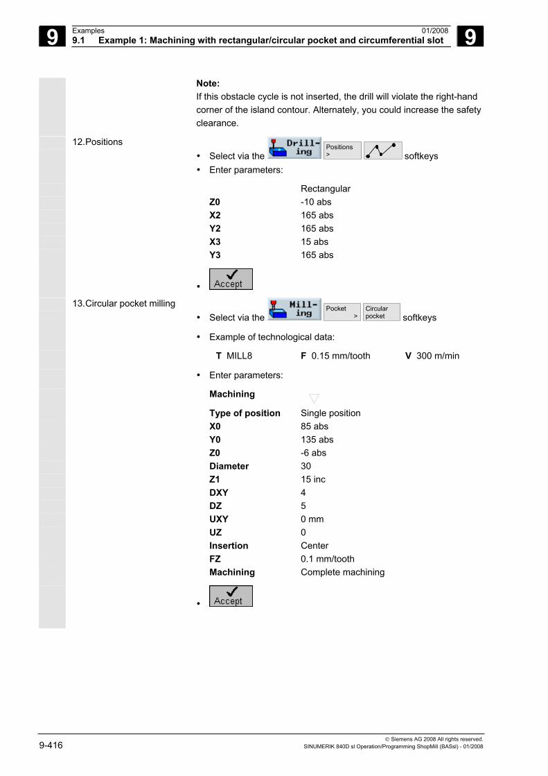
9 Examples 01/2008 9.1 Example 1: Machining with rectangular/circular pocket and circumferential slot
9
© Siemens AG 2008 All rights reserved. 9-416 SINUMERIK 840D sl Operation/Programming ShopMill (BASsl) - 01/2008
Note: If this obstacle cycle is not inserted, the drill will violate the right-hand corner of the island contour. Alternately, you could increase the safety clearance.
12. Positions • Select via the
Positions >
softkeys
• Enter parameters:
Rectangular Z0 -10 abs X2 165 abs Y2 165 abs X3 15 abs Y3 165 abs
•
13. Circular pocket milling • Select via the
Pocket >
Circular pocket softkeys
• Example of technological data:
T MILL8 F 0.15 mm/tooth V 300 m/min
• Enter parameters:
Machining
Type of position Single position X0 85 abs Y0 135 abs Z0 -6 abs Diameter 30 Z1 15 inc DXY 4 DZ 5 UXY 0 mm UZ 0 Insertion Center FZ 0.1 mm/tooth Machining Complete machining
•
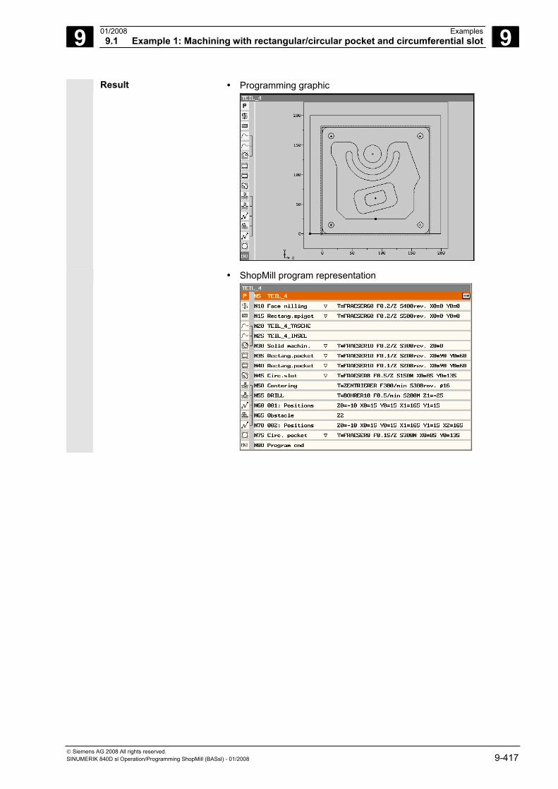
9 01/2008 Examples9.1 Example 1: Machining with rectangular/circular pocket and circumferential slot
9
© Siemens AG 2008 All rights reserved. SINUMERIK 840D sl Operation/Programming ShopMill (BASsl) - 01/2008 9-417
Result • Programming graphic
• ShopMill program representation
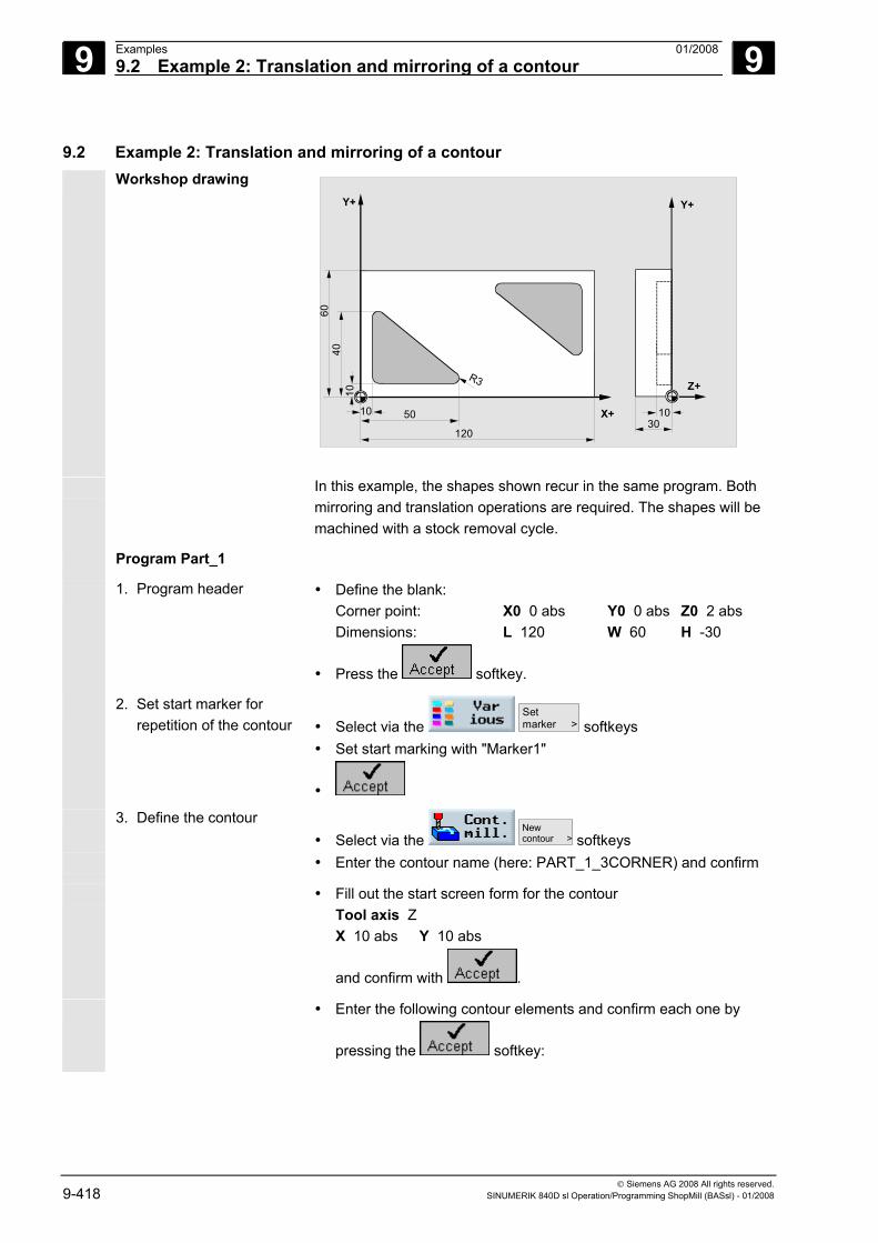
9 Examples 01/2008 9.2 Example 2: Translation and mirroring of a contour
9
© Siemens AG 2008 All rights reserved. 9-418 SINUMERIK 840D sl Operation/Programming ShopMill (BASsl) - 01/2008
9.2 Example 2: Translation and mirroring of a contour Workshop drawing
X+
Y+
Z+
Y+
12030
5010
6040
10
R3
10
In this example, the shapes shown recur in the same program. Both mirroring and translation operations are required. The shapes will be machined with a stock removal cycle.
Program Part_1
1. Program header • Define the blank: Corner point: X0 0 abs Y0 0 abs Z0 2 abs Dimensions: L 120 W 60 H -30
• Press the softkey.
2. Set start marker for repetition of the contour • Select via the
Setmarker > softkeys
• Set start marking with "Marker1"
•
3. Define the contour • Select via the
New contour > softkeys
• Enter the contour name (here: PART_1_3CORNER) and confirm
• Fill out the start screen form for the contour Tool axis Z X 10 abs Y 10 abs
and confirm with .
• Enter the following contour elements and confirm each one by
pressing the softkey:
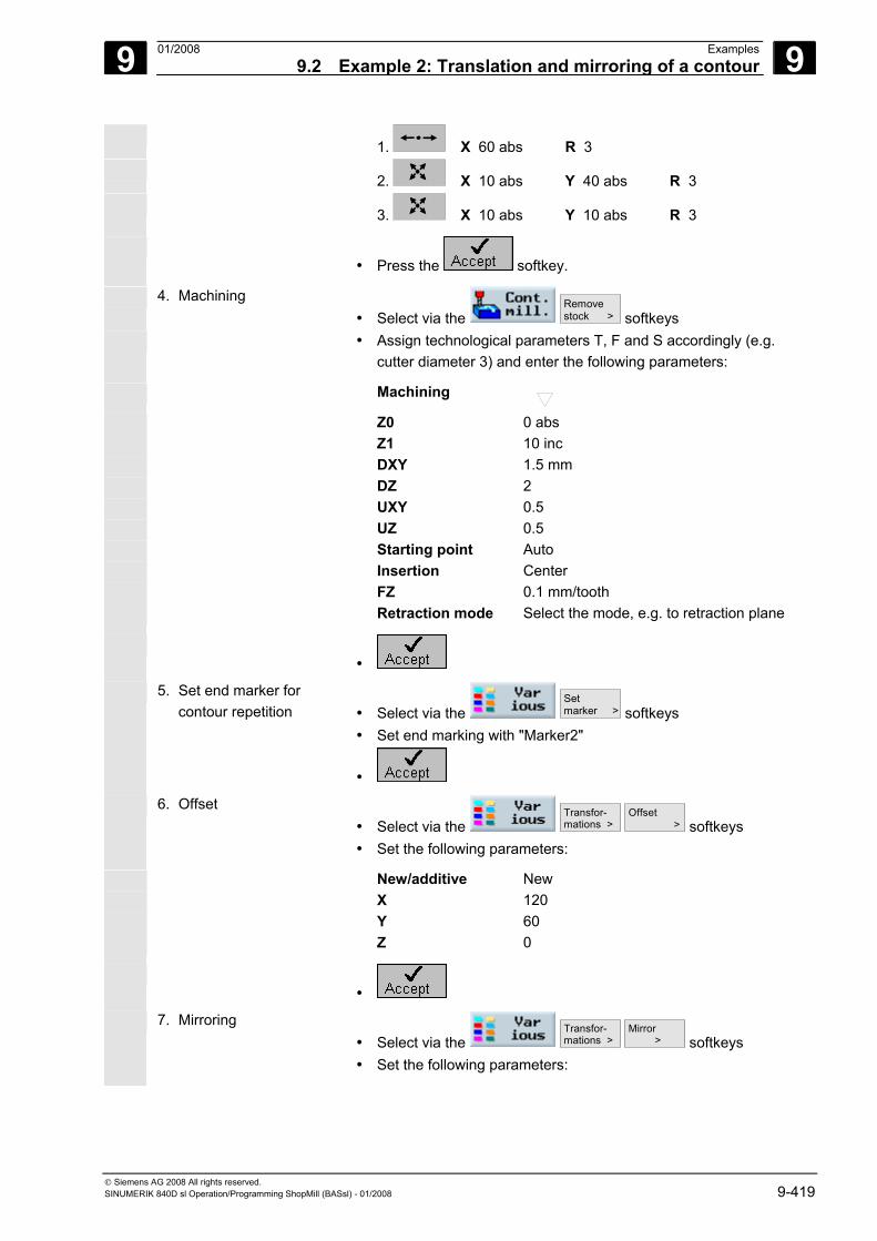
9 01/2008 Examples9.2 Example 2: Translation and mirroring of a contour
9
© Siemens AG 2008 All rights reserved. SINUMERIK 840D sl Operation/Programming ShopMill (BASsl) - 01/2008 9-419
1. X 60 abs R 3
2. X 10 abs Y 40 abs R 3
3. X 10 abs Y 10 abs R 3
• Press the softkey.
4. Machining • Select via the
Remove stock > softkeys
• Assign technological parameters T, F and S accordingly (e.g. cutter diameter 3) and enter the following parameters:
Machining
Z0 0 abs Z1 10 inc DXY 1.5 mm DZ 2 UXY 0.5 UZ 0.5 Starting point Auto Insertion Center FZ 0.1 mm/tooth Retraction mode Select the mode, e.g. to retraction plane
•
5. Set end marker for contour repetition • Select via the
Setmarker > softkeys
• Set end marking with "Marker2"
•
6. Offset • Select via the
Transfor- mations >
Offset > softkeys
• Set the following parameters:
New/additive New X 120 Y 60 Z 0
•
7. Mirroring • Select via the
Transfor- mations >
Mirror > softkeys
• Set the following parameters:
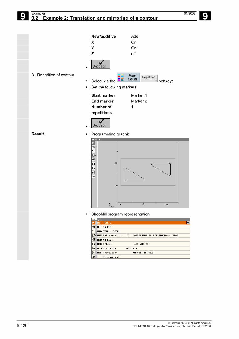
9 Examples 01/2008 9.2 Example 2: Translation and mirroring of a contour
9
© Siemens AG 2008 All rights reserved. 9-420 SINUMERIK 840D sl Operation/Programming ShopMill (BASsl) - 01/2008
New/additive Add X On Y On Z off
•
8. Repetition of contour • Select via the
Repetition > softkeys
• Set the following markers:
Start marker Marker 1 End marker Marker 2 Number of
repetitions 1
•
Result • Programming graphic
• ShopMill program representation
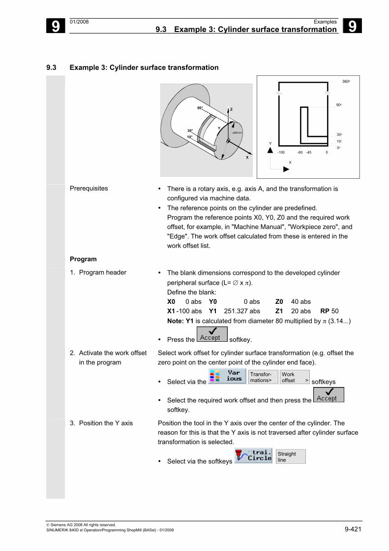
9 01/2008 Examples9.3 Example 3: Cylinder surface transformation
9
© Siemens AG 2008 All rights reserved. SINUMERIK 840D sl Operation/Programming ShopMill (BASsl) - 01/2008 9-421
9.3 Example 3: Cylinder surface transformation
Z
Y
X
90°
10°30° o80mm
360o
90o
30o
10o
0o
0-45-60-100
Y
X
Prerequisites • There is a rotary axis, e.g. axis A, and the transformation is configured via machine data.
• The reference points on the cylinder are predefined. Program the reference points X0, Y0, Z0 and the required work offset, for example, in "Machine Manual", "Workpiece zero", and "Edge". The work offset calculated from these is entered in the work offset list.
Program
1. Program header • The blank dimensions correspond to the developed cylinder peripheral surface (L= ∅ x π). Define the blank:
X0 0 abs Y0 0 abs Z0 40 abs X1 -100 abs Y1 251.327 abs Z1 20 abs RP 50
Note: Y1 is calculated from diameter 80 multiplied by π (3.14...)
• Press the softkey.
2. Activate the work offset in the program
Select work offset for cylinder surface transformation (e.g. offset the zero point on the center point of the cylinder end face).
• Select via the Transfor- mations>
Workoffset > softkeys
• Select the required work offset and then press the softkey.
3. Position the Y axis Position the tool in the Y axis over the center of the cylinder. The reason for this is that the Y axis is not traversed after cylinder surface transformation is selected.
• Select via the softkeys Straightline
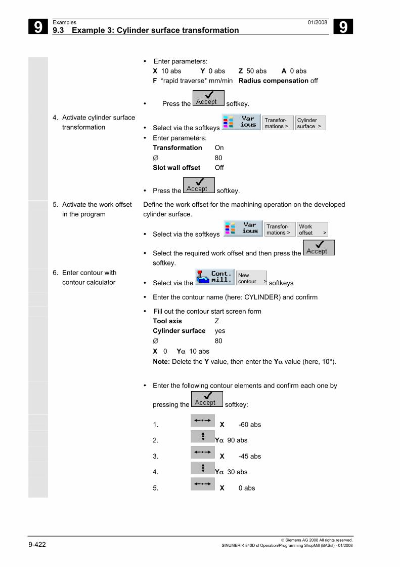
9 Examples 01/2008 9.3 Example 3: Cylinder surface transformation
9
© Siemens AG 2008 All rights reserved. 9-422 SINUMERIK 840D sl Operation/Programming ShopMill (BASsl) - 01/2008
• Enter parameters: X 10 abs Y 0 abs Z 50 abs A 0 abs F *rapid traverse* mm/min Radius compensation off
• Press the softkey.
4. Activate cylinder surface transformation • Select via the softkeys
Transfor- mations >
Cylinder surface >
• Enter parameters: Transformation On ∅ 80 Slot wall offset Off
• Press the softkey.
5. Activate the work offset in the program
Define the work offset for the machining operation on the developed cylinder surface.
• Select via the softkeys Transfor- mations >
Workoffset >
• Select the required work offset and then press the softkey.
6. Enter contour with contour calculator • Select via the
New contour > softkeys
• Enter the contour name (here: CYLINDER) and confirm
• Fill out the contour start screen form Tool axis Z Cylinder surface yes ∅ 80 X 0 Yα 10 abs Note: Delete the Y value, then enter the Yα value (here, 10°).
• Enter the following contour elements and confirm each one by
pressing the softkey:
1. X -60 abs
2. Yα 90 abs
3. X -45 abs
4. Yα 30 abs
5. X 0 abs
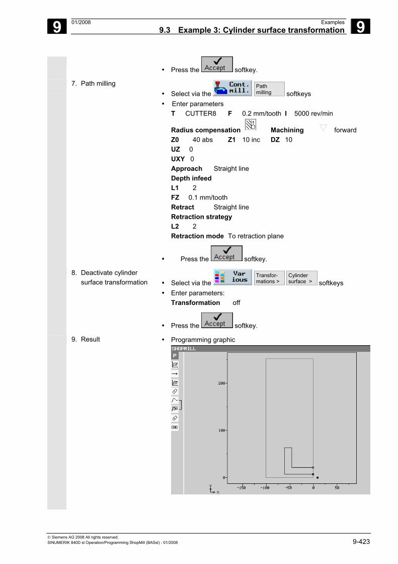
9 01/2008 Examples9.3 Example 3: Cylinder surface transformation
9
© Siemens AG 2008 All rights reserved. SINUMERIK 840D sl Operation/Programming ShopMill (BASsl) - 01/2008 9-423
• Press the softkey.
7. Path milling • Select via the
Pathmilling softkeys
• Enter parameters T CUTTER8 F 0.2 mm/tooth I 5000 rev/min
Radius compensation Machining forward Z0 40 abs Z1 10 inc DZ 10 UZ 0 UXY 0 Approach Straight line Depth infeed L1 2 FZ 0.1 mm/tooth Retract Straight line Retraction strategy L2 2 Retraction mode To retraction plane
• Press the softkey.
8. Deactivate cylinder surface transformation • Select via the
Transfor- mations >
Cylinder surface > softkeys
• Enter parameters: Transformation off
• Press the softkey.
9. Result • Programming graphic
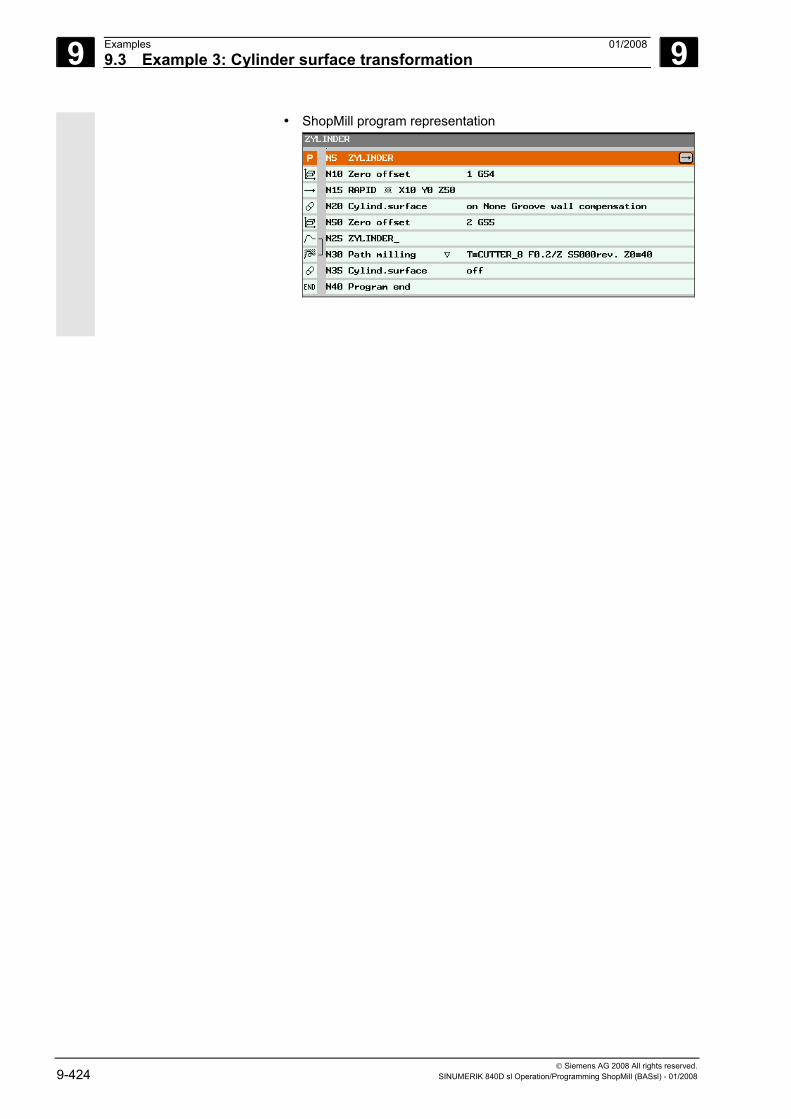
9 Examples 01/2008 9.3 Example 3: Cylinder surface transformation
9
© Siemens AG 2008 All rights reserved. 9-424 SINUMERIK 840D sl Operation/Programming ShopMill (BASsl) - 01/2008
• ShopMill program representation
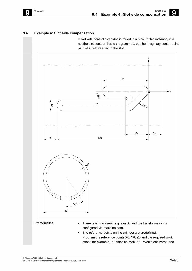
9 01/2008 Examples9.4 Example 4: Slot side compensation
9
© Siemens AG 2008 All rights reserved. SINUMERIK 840D sl Operation/Programming ShopMill (BASsl) - 01/2008 9-425
9.4 Example 4: Slot side compensation A slot with parallel slot sides is milled in a pipe. In this instance, it is
not the slot contour that is programmed, but the imaginary center-pointpath of a bolt inserted in the slot.
50
35o
3
12
50
y
x
100
25 1515
45 o
35o
Prerequisites • There is a rotary axis, e.g. axis A, and the transformation is configured via machine data.
• The reference points on the cylinder are predefined. Program the reference points X0, Y0, Z0 and the required work offset, for example, in "Machine Manual", "Workpiece zero", and
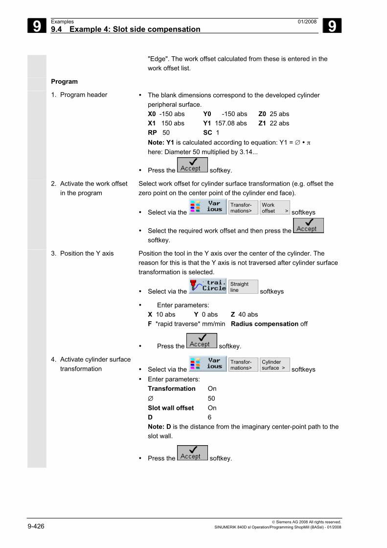
9 Examples 01/2008 9.4 Example 4: Slot side compensation
9
© Siemens AG 2008 All rights reserved. 9-426 SINUMERIK 840D sl Operation/Programming ShopMill (BASsl) - 01/2008
"Edge". The work offset calculated from these is entered in the work offset list.
Program
1. Program header • The blank dimensions correspond to the developed cylinder peripheral surface.
X0 -150 abs Y0 -150 abs Z0 25 abs X1 150 abs Y1 157.08 abs Z1 22 abs
RP 50 SC 1 Note: Y1 is calculated according to equation: Y1 = ∅ • π here: Diameter 50 multiplied by 3.14...
• Press the softkey.
2. Activate the work offset in the program
Select work offset for cylinder surface transformation (e.g. offset the zero point on the center point of the cylinder end face).
• Select via the Transfor- mations>
Workoffset > softkeys
• Select the required work offset and then press the softkey.
3. Position the Y axis Position the tool in the Y axis over the center of the cylinder. The reason for this is that the Y axis is not traversed after cylinder surface transformation is selected.
• Select via the Straightline softkeys
• Enter parameters: X 10 abs Y 0 abs Z 40 abs F *rapid traverse* mm/min Radius compensation off
• Press the softkey.
4. Activate cylinder surface transformation • Select via the
Transfor- mations>
Cylinder surface > softkeys
• Enter parameters: Transformation On ∅ 50 Slot wall offset On D 6 Note: D is the distance from the imaginary center-point path to the slot wall.
• Press the softkey.
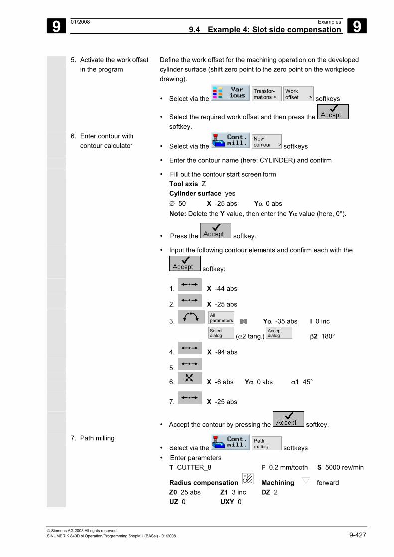
9 01/2008 Examples9.4 Example 4: Slot side compensation
9
© Siemens AG 2008 All rights reserved. SINUMERIK 840D sl Operation/Programming ShopMill (BASsl) - 01/2008 9-427
5. Activate the work offset in the program
Define the work offset for the machining operation on the developed cylinder surface (shift zero point to the zero point on the workpiece drawing).
• Select via the Transfor- mations >
Workoffset > softkeys
• Select the required work offset and then press the softkey.
6. Enter contour with contour calculator • Select via the
New contour > softkeys
• Enter the contour name (here: CYLINDER) and confirm
• Fill out the contour start screen form Tool axis Z Cylinder surface yes ∅ 50 X -25 abs Yα 0 abs Note: Delete the Y value, then enter the Yα value (here, 0°).
• Press the softkey.
• Input the following contour elements and confirm each with the
softkey:
1. X -44 abs
2. X -25 abs
3.
Allparameters Yα -35 abs I 0 inc
Selectdialog (α2 tang.)
Acceptdialog β2 180°
4. X -94 abs
5.
6. X -6 abs Yα 0 abs α1 45°
7. X -25 abs
• Accept the contour by pressing the softkey.
7. Path milling • Select via the
Pathmilling softkeys
• Enter parameters T CUTTER_8 F 0.2 mm/tooth S 5000 rev/min
Radius compensation Machining forward Z0 25 abs Z1 3 inc DZ 2 UZ 0 UXY 0
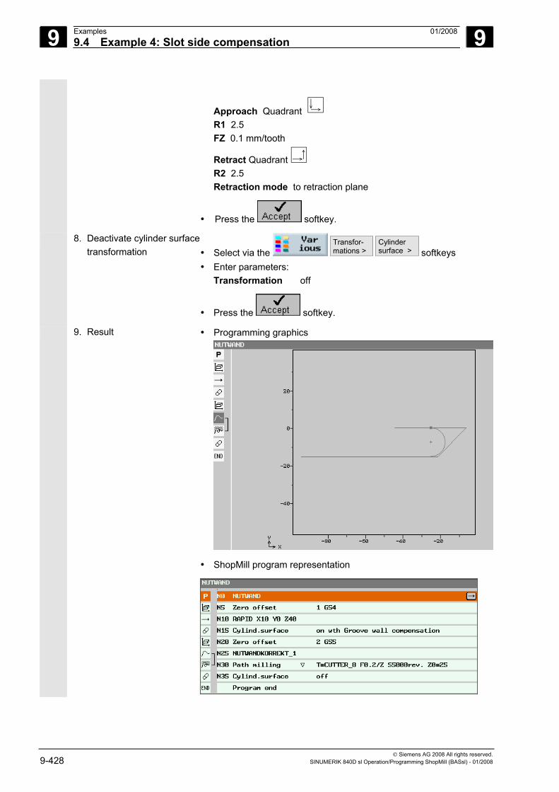
9 Examples 01/2008 9.4 Example 4: Slot side compensation
9
© Siemens AG 2008 All rights reserved. 9-428 SINUMERIK 840D sl Operation/Programming ShopMill (BASsl) - 01/2008
Approach Quadrant R1 2.5 FZ 0.1 mm/tooth
Retract Quadrant R2 2.5 Retraction mode to retraction plane
• Press the softkey.
8. Deactivate cylinder surface transformation • Select via the
Transfor-mations >
Cylinder surface > softkeys
• Enter parameters: Transformation off
• Press the softkey.
9. Result • Programming graphics
• ShopMill program representation
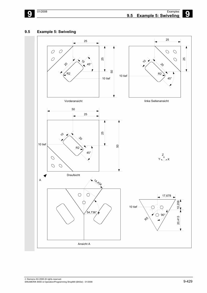
9 01/2008 Examples9.5 Example 5: Swiveling
9
© Siemens AG 2008 All rights reserved. SINUMERIK 840D sl Operation/Programming ShopMill (BASsl) - 01/2008 9-429
9.5 Example 5: Swiveling
54,736°
Ansicht A
14,434
Vorderansicht
50
25
25
2010
45°
10 tief
linke Seitenansicht
10 tief
25
25
10 20
45°
ZXY
17,678
20,4
1310
,206
R5
10 tief
90°
A
Draufsicht
10 tief
25
25
10 20
45°
50
50
R2
R2
R2
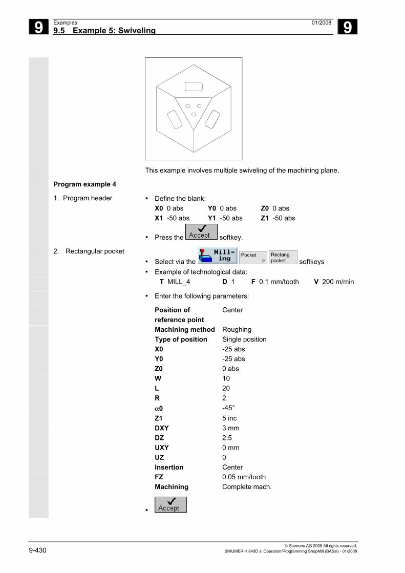
9 Examples 01/2008 9.5 Example 5: Swiveling
9
© Siemens AG 2008 All rights reserved. 9-430 SINUMERIK 840D sl Operation/Programming ShopMill (BASsl) - 01/2008
This example involves multiple swiveling of the machining plane.
Program example 4
1. Program header • Define the blank: X0 0 abs Y0 0 abs Z0 0 abs X1 -50 abs Y1 -50 abs Z1 -50 abs
• Press the softkey.
2. Rectangular pocket • Select via the
Pocket >
Rectang.pocket softkeys
• Example of technological data: T MILL_4 D 1 F 0.1 mm/tooth V 200 m/min
• Enter the following parameters:
Position of reference point
Center
Machining method Roughing Type of position Single position X0 -25 abs Y0 -25 abs Z0 0 abs W 10 L 20 R 2 α0 -45° Z1 5 inc DXY 3 mm DZ 2.5 UXY 0 mm UZ 0 Insertion Center FZ 0.05 mm/tooth Machining Complete mach.
•
9 01/2008 Examples9.5 Example 5: Swiveling
9
© Siemens AG 2008 All rights reserved. SINUMERIK 840D sl Operation/Programming ShopMill (BASsl) - 01/2008 9-431
3. Swiveling • Select via the
Transfor-mations >
Swiveling > softkeys
• Example of technological data: T MILL_4 D 1
• Enter the following parameters:
Retraction Yes Swiveling Yes Transformation New X0 0 Y0 -50 Z0 0 Swiveling Axis by axis X 90° Y 0° Z 0° X1 0 Y1 0 Z1 0 Direction -
•
4. Rectangular pocket • Select via the
Pocket >
Rectang.pocket softkeys
• Example of technological data: T MILL_4 D 1 F 0.1 mm/tooth V 200 m/min
• Enter the following parameters:
Position of reference point
Center
Machining method Roughing Type of position Single position X0 -25 abs Y0 -25 abs Z0 0 abs W 10 L 20 R 2 α0 45° Z1 5 inc DXY 3 mm DZ 2.5 UXY 0 mm UZ 0 Insertion Center FZ 0.05 mm/tooth Machining Complete mach.
9 Examples 01/2008 9.5 Example 5: Swiveling
9
© Siemens AG 2008 All rights reserved. 9-432 SINUMERIK 840D sl Operation/Programming ShopMill (BASsl) - 01/2008
•
5. Swiveling • Select via the
Transfor-mations >
Swiveling > softkeys
• Example of technological data: T MILL_4 D 1
• Enter the following parameters:
Retraction Yes Swiveling Yes Transformation New X0 -50 Y0 -50 Z0 0 Swiveling Axis by axis Z -90° X 90° Y 0° X1 0 Y1 0 Z1 0 Direction -
•
6. Rectangular pocket • Select via the
Pocket >
Rectang.pocket softkeys
• Example of technological data: T MILL_4 D 1 F 0.1 mm/tooth V 200 m/min
• Enter the following parameters:
Position of reference point
Center
Machining method Roughing Type of position Single position X0 -25 abs Y0 -25 abs Z0 0 abs W 10 L 20 R 2 α0 -45° Z1 5 inc DXY 3 mm DZ 2.5 UXY 0 mm UZ 0 Insertion Center
9 01/2008 Examples9.5 Example 5: Swiveling
9
© Siemens AG 2008 All rights reserved. SINUMERIK 840D sl Operation/Programming ShopMill (BASsl) - 01/2008 9-433
FZ 0.05 mm/tooth Machining Complete mach.
•
7. Settings Define a different blank so that the visible section of the simulation shows the machining of the inclined plane:
• Select via the
Settings softkeys
• Define the blank: X0 -17.678 abs Y0 10,206 abs Z0 0 abs X1 17,678 abs Y1 -20.413 abs Z1 -10 abs
• Press the softkey.
•
8. Swiveling • Select via the
Transfor- mations
Swiveling > softkeys
• Example of technological data: T FACING TOOL D 1
• Enter the following parameters:
Retraction Yes Swiveling Yes Transformation New X0 -50 Y0 -50 Z0 -25 Swiveling Axis by axis Z -45° X 54.736° Y 0° X1 0 Y1 20.413 Z1 0 Direction -
•
9. Face milling • Select via the
Facemilling > softkeys and choose a
machining strategy. • Example of technological data:
T FACING TOOL D 1 F 0.1 mm/tooth V 200 m/min
• Enter the following parameters:
Machining method Roughing X0 -17.678 abs
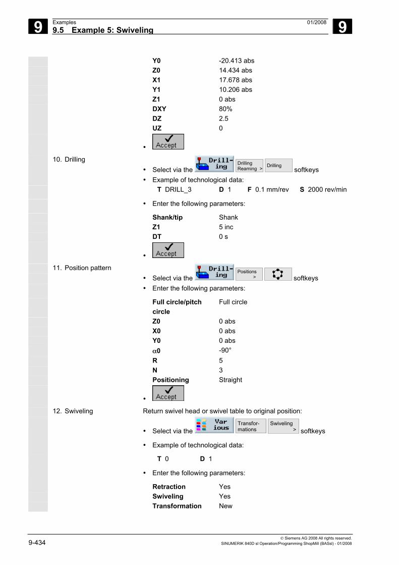
9 Examples 01/2008 9.5 Example 5: Swiveling
9
© Siemens AG 2008 All rights reserved. 9-434 SINUMERIK 840D sl Operation/Programming ShopMill (BASsl) - 01/2008
Y0 -20.413 abs Z0 14.434 abs X1 17.678 abs Y1 10.206 abs Z1 0 abs DXY 80% DZ 2.5 UZ 0
•
10. Drilling • Select via the
DrillingReaming >
Drilling softkeys
• Example of technological data: T DRILL_3 D 1 F 0.1 mm/rev S 2000 rev/min
• Enter the following parameters:
Shank/tip Shank Z1 5 inc DT 0 s
•
11. Position pattern • Select via the
Positions > softkeys
• Enter the following parameters:
Full circle/pitch circle
Full circle
Z0 0 abs X0 0 abs Y0 0 abs α0 -90° R 5 N 3 Positioning Straight
•
12. Swiveling Return swivel head or swivel table to original position:
• Select via the Transfor- mations
Swiveling > softkeys
• Example of technological data:
T 0 D 1
• Enter the following parameters:
Retraction Yes Swiveling Yes Transformation New
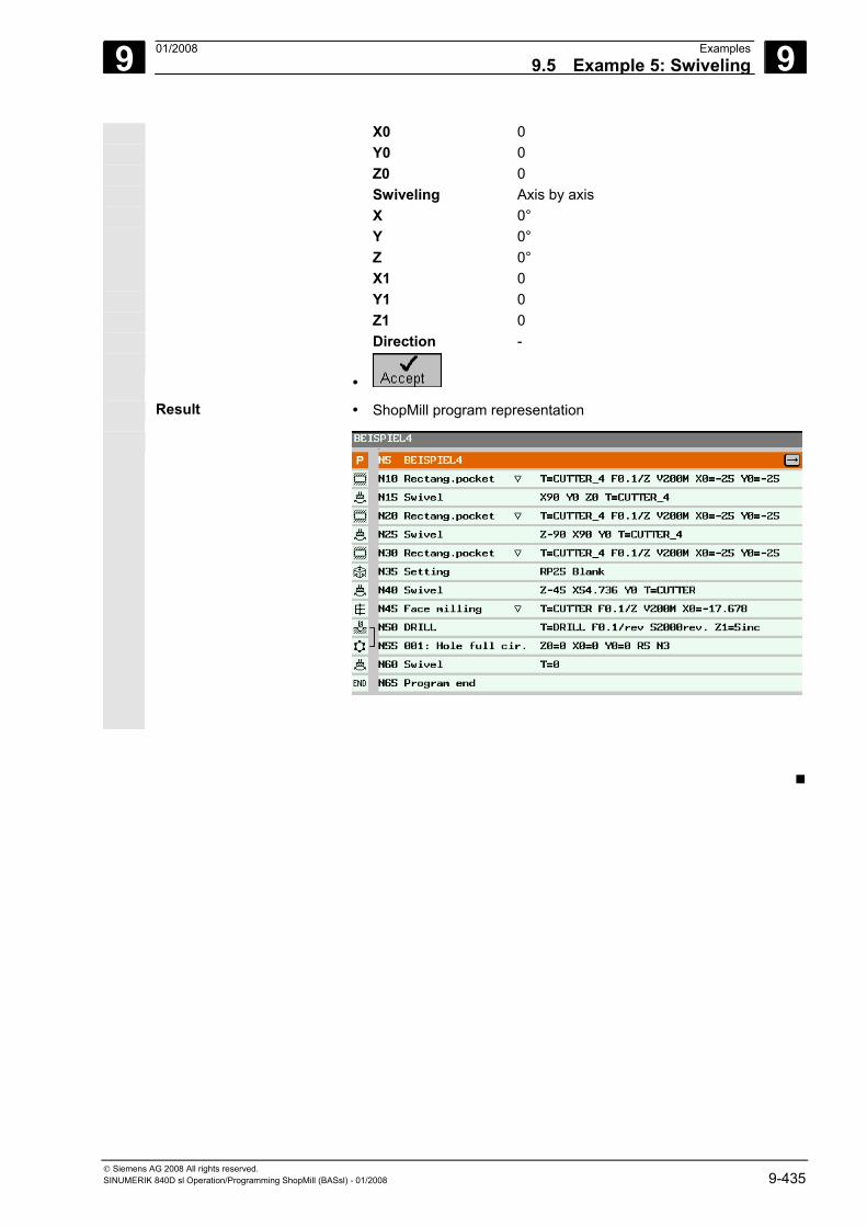
9 01/2008 Examples9.5 Example 5: Swiveling
9
© Siemens AG 2008 All rights reserved. SINUMERIK 840D sl Operation/Programming ShopMill (BASsl) - 01/2008 9-435
X0 0 Y0 0 Z0 0 Swiveling Axis by axis X 0° Y 0° Z 0° X1 0 Y1 0 Z1 0 Direction -
•
Result • ShopMill program representation
9 Examples 01/2008 9.5 Example 5: Swiveling
9
© Siemens AG 2008 All rights reserved. 9-436 SINUMERIK 840D sl Operation/Programming ShopMill (BASsl) - 01/2008
Notes
A 01/2008 Appendix A
© Siemens AG 2008 All rights reserved. SINUMERIK 840D sl Operation/Programming ShopMill (BASsl) - 01/2008 A-437
Appendix A Abbreviations ..........................................................................................................A-438
B Index ........................................................................................................................ I-441
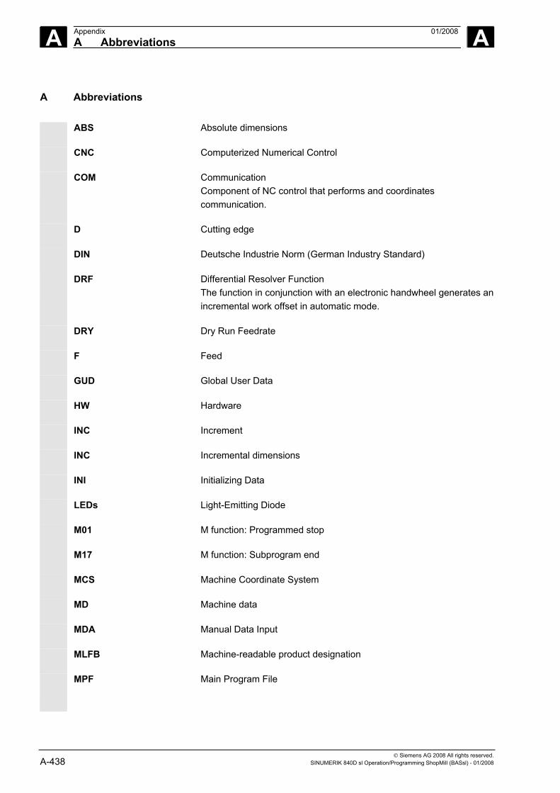
A Appendix 01/2008 A Abbreviations
A
© Siemens AG 2008 All rights reserved. A-438 SINUMERIK 840D sl Operation/Programming ShopMill (BASsl) - 01/2008
A Abbreviations ABS Absolute dimensions
CNC Computerized Numerical Control
COM Communication Component of NC control that performs and coordinates communication.
D Cutting edge
DIN Deutsche Industrie Norm (German Industry Standard)
DRF Differential Resolver Function The function in conjunction with an electronic handwheel generates an incremental work offset in automatic mode.
DRY Dry Run Feedrate
F Feed
GUD Global User Data
HW Hardware
INC Increment
INC Incremental dimensions
INI Initializing Data
LEDs Light-Emitting Diode
M01 M function: Programmed stop
M17 M function: Subprogram end
MCS Machine Coordinate System
MD Machine data
MDA Manual Data Input
MLFB Machine-readable product designation
MPF Main Program File
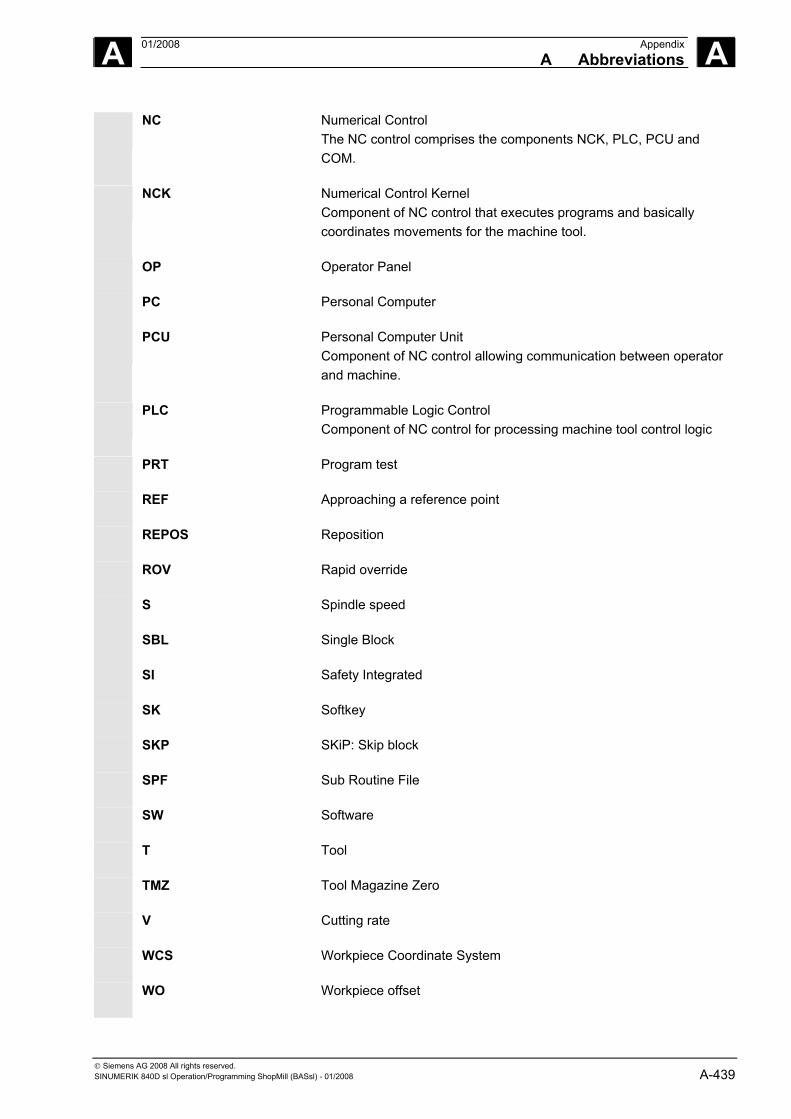
A 01/2008 AppendixA Abbreviations
A
© Siemens AG 2008 All rights reserved. SINUMERIK 840D sl Operation/Programming ShopMill (BASsl) - 01/2008 A-439
NC Numerical Control The NC control comprises the components NCK, PLC, PCU and COM.
NCK Numerical Control Kernel Component of NC control that executes programs and basically coordinates movements for the machine tool.
OP Operator Panel
PC Personal Computer
PCU Personal Computer Unit Component of NC control allowing communication between operator and machine.
PLC Programmable Logic Control Component of NC control for processing machine tool control logic
PRT Program test
REF Approaching a reference point
REPOS Reposition
ROV Rapid override
S Spindle speed
SBL Single Block
SI Safety Integrated
SK Softkey
SKP SKiP: Skip block
SPF Sub Routine File
SW Software
T Tool
TMZ Tool Magazine Zero
V Cutting rate
WCS Workpiece Coordinate System
WO Workpiece offset
A Appendix 01/2008 A Abbreviations
A
© Siemens AG 2008 All rights reserved. A-440 SINUMERIK 840D sl Operation/Programming ShopMill (BASsl) - 01/2008
WPD Workpiece Directory
WZ Tool
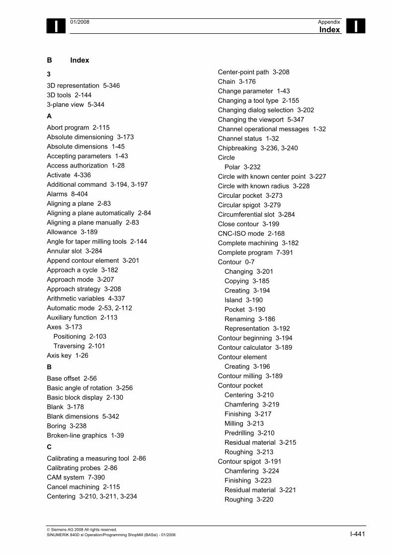
I 01/2008 AppendixIndex
I
© Siemens AG 2008 All rights reserved. SINUMERIK 840D sl Operation/Programming ShopMill (BASsl) - 01/2008 I-441
B Index
3
3D representation 5-346 3D tools 2-144 3-plane view 5-344
A
Abort program 2-115 Absolute dimensioning 3-173 Absolute dimensions 1-45 Accepting parameters 1-43 Access authorization 1-28 Activate 4-336 Additional command 3-194, 3-197 Alarms 8-404 Aligning a plane 2-83 Aligning a plane automatically 2-84 Aligning a plane manually 2-83 Allowance 3-189 Angle for taper milling tools 2-144 Annular slot 3-284 Append contour element 3-201 Approach a cycle 3-182 Approach mode 3-207 Approach strategy 3-208 Arithmetic variables 4-337 Automatic mode 2-53, 2-112 Auxiliary function 2-113 Axes 3-173
Positioning 2-103 Traversing 2-101
Axis key 1-26
B
Base offset 2-56 Basic angle of rotation 3-256 Basic block display 2-130 Blank 3-178 Blank dimensions 5-342 Boring 3-238 Broken-line graphics 1-39
C
Calibrating a measuring tool 2-86 Calibrating probes 2-86 CAM system 7-390 Cancel machining 2-115 Centering 3-210, 3-211, 3-234
Center-point path 3-208 Chain 3-176 Change parameter 1-43 Changing a tool type 2-155 Changing dialog selection 3-202 Changing the viewport 5-347 Channel operational messages 1-32 Channel status 1-32 Chipbreaking 3-236, 3-240 Circle
Polar 3-232 Circle with known center point 3-227 Circle with known radius 3-228 Circular pocket 3-273 Circular spigot 3-279 Circumferential slot 3-284 Close contour 3-199 CNC-ISO mode 2-168 Complete machining 3-182 Complete program 7-391 Contour 0-7
Changing 3-201 Copying 3-185 Creating 3-194 Island 3-190 Pocket 3-190 Renaming 3-186 Representation 3-192
Contour beginning 3-194 Contour calculator 3-189 Contour element
Creating 3-196 Contour milling 3-189 Contour pocket
Centering 3-210 Chamfering 3-219 Finishing 3-217 Milling 3-213 Predrilling 3-210 Residual material 3-215 Roughing 3-213
Contour spigot 3-191 Chamfering 3-224 Finishing 3-223 Residual material 3-221 Roughing 3-220
I Appendix 01/2008 Index
I
© Siemens AG 2008 All rights reserved. I-442 SINUMERIK 840D sl Operation/Programming ShopMill (BASsl) - 01/2008
Contour transition element 3-197 Coolant 2-150, 3-323 Coordinate system 1-21 Coordinate transformation 2-162
Defining 3-311 Corner point 3-178 Count 2-152 Creating a directory 6-366, 6-381 Cutter radius compensation 3-174 Cutting edge 3-188 Cutting rate 3-174, 3-188 Cycle 0-7 Cycle approach 3-182 Cycle support 4-328 Cylinder surface transformation 3-196, 3-314
D
D 3-188 Deep-hole drilling 3-236 Default settings
Changing 2-110 Delete contour element 3-203 Dialog line 1-31 Direction of spindle rotation 2-150, 3-323 Directory
Copying 6-368, 6-383 Deleting 6-369, 6-385 Moving 6-384 Renaming 6-369, 6-384 Selecting 6-361, 6-375
Disable magazine location 2-155 DR 3-189 DRF offset 2-123 Drill 2-137, 2-138 Drill and thread milling 3-245 Drilling 3-234, 3-235 Duplo number 2-140
E
E_COUNTER 3-324 EMERGENCY OFF 1-25 End 4-336 End of contour 3-194 End of program 3-187 Engraving 3-295 Entering parameters 1-42 Equidistant 2-149
Example Cylinder surface transformation 9-421 Drilling 3-264 Face milling 3-268 Freely defined contours 3-203 Polar coordinates 3-233 Position pattern milling 3-293 Rectanglar pocket 3-272 Slot side compensation 9-425 Swiveling 3-321, 9-429 Thread milling 3-244
Examples 9-410, 9-418 Execution 2-112 External thread 3-242
F
Face milling 2-107, 3-220 Feed 3-181 Feedrate override 1-27 Feedrate status 1-32 Finding an empty location 2-157, 2-159 Fine offset 2-163 Finishing 2-97, 2-98, 3-182 Fixed point
Calibrating 2-92 Floppy disk drive 6-380 FOR 3-324
G
G code Copying 4-334 Cutting 4-334 Finding 4-335 Into sequence program 3-324 Pasting 4-334 Selecting 4-334 Skipping 2-123
G code block Renumbering 4-336
G code editor 4-333 G code program
Executing 4-331, 6-365, 6-380 G Functions 2-113 Gear stage 3-323 Geometry program 7-390
I 01/2008 AppendixIndex
I
© Siemens AG 2008 All rights reserved. SINUMERIK 840D sl Operation/Programming ShopMill (BASsl) - 01/2008 I-443
H
H functions 2-113 H number 2-140 Hard disk 6-380 Helix 3-229 Help screen 1-41 High speed settings 7-393
I Inch/metric switchover 2-54 Increment 2-101 Incremental dimension 1-45, 3-173 Input box 1-42 Insert a contour element 3-202 Insert mode 1-43 Insertion 3-271 Inside contour 3-197 Internal thread 3-241 ISO dialect 2-140, 4-338
J
Jog 1-25
K
Key-operated switch 1-28 Keys 1-23
Operation 1-34
L
Lateral offset 2-93, 3-302 Loading a program 6-379 Location assignment 2-141 Location number 2-139 Longitudinal offset 2-93, 3-302 Longitudinal slot 3-281 Lowercase letters 3-296
M
M functions 2-113, 3-323 Machine control panel 1-25 Machine coordinate system 2-55 Machine run times 2-132 Machine zero 1-21 Machining
Stopping 2-115 Machining direction 3-179 Machining lines 5-340 Magazine 2-154 Magazine list 2-154
Magazine location Positioning 2-160
Main program 3-305 Manual mode 2-53
Default settings 2-110 Gear stage 2-108 M functions 2-108 Tool axis 2-109 Traversing axes 2-101 Unit of measurement 2-109
Manual tools 2-146 Marker 3-307 MCS/WCS 2-55 MDA 2-53 MDA mode 2-111 Measurement 3-300 Measuring
Tool 2-88 Workpiece zero 2-58, 3-300
Measuring a circular spigot automatically Measuring 1 circular spigot 2-78 Measuring 2 circular spigot 2-79 Measuring 3 circular spigot 2-80 Measuring 4 circular spigot 2-81
Measuring a circular spigot manually Measuring 1 circular spigot 2-78
Measuring a corner 2-67 Measuring a corner automatically
Measuring right-angled/any corner 2-68 Measuring a corner manually
Measuring right-angled/any corner 2-67 Measuring a hole automatically
Measuring 1 hole 2-71 Measuring 2 holes 2-72 Measuring 3 holes 2-73 Measuring 4 holes 2-74
Measuring a pocket Measuring a rectangular pocket manually 2-70
Measuring a pocket automatically Measuring a rectangular pocket 2-70
Measuring a spigot 2-76 Measuring a rectangular spigot 2-77
Measuring a spigot automatically Measuring a rectangular spigot 2-77
Measuring an edge 2-62
I Appendix 01/2008 Index
I
© Siemens AG 2008 All rights reserved. I-444 SINUMERIK 840D sl Operation/Programming ShopMill (BASsl) - 01/2008
Measuring an edge automatically Measuring one point 2-64 Measuring the distance between 2 edges 2-66 Measuring two points 2-65
Measuring an edge manually Measuring one point 2-63 Measuring the distance between 2 edges 2-65 Measuring two points 2-64
Measuring cycle support 4-328 Measuring pockets/holes 2-69 Messages 8-404 Metric/inch switchover 2-54 Milling 3-266 Milling tool 2-137, 2-138 Mini hand-held device 1-29 Mirror writing 3-296 Mirroring 3-312 Miscellaneous function 3-323
Tool 2-150 Modifying contour element 3-201 Mold making 7-390 Multiple clamping 6-362, 6-376
N
Network drive 6-365, 6-380 New contour
Milling 3-194 Number of teeth 2-150 Number of workpieces 3-187
O
Obstacle 3-261 Offset 3-311 Offset values 2-149 Online Help 4-328 Open directory 6-361, 6-375 Operation 1-34 Operator panel 1-22
Keys 1-23 Operator panel OP 010 1-22 Outside contour 3-197
P
Parameter Calculating 1-43 Deleting 1-43
Parameterization screen form 1-40 Password 0-4, 1-28 Path milling 3-207
Plan view 5-343 Plane designations 1-44 Plunge cutting 3-288 Plunging 3-288 Polar coordinates 1-44, 3-230 Pole 3-230 Position
Freely programmable 3-248 Position
Repeating 3-263 Position pattern
Box 3-254 Full circle 3-256 Line 3-252 Matrix 3-253 Milling 3-292 Pitch circle 3-258 Rhombus 3-253
Position value 2-56 Positioning 3-247 Positioning movements 3-225 POWER ON 8-405 Predrilling 3-210, 3-212 Pre-warning limit 2-152 Probe 2-93
Calibration 2-96, 3-304 Process plan 1-39 Processing time 5-340 Program 0-7
Copying 6-368, 6-383 Correcting 2-131 Creating 6-366, 6-381 Deleting 6-369, 6-385 Executing 6-362, 6-376 Interrupting 2-116 Moving 6-384 New 3-177 Opening 6-361, 6-375 Overstoring 2-124 Renaming 6-369, 6-384 Selecting for execution 2-114 Selecting several 6-367, 6-382 Stopping 2-115 Testing 2-125 Trial run 2-129 Unload 6-379
I 01/2008 AppendixIndex
I
© Siemens AG 2008 All rights reserved. SINUMERIK 840D sl Operation/Programming ShopMill (BASsl) - 01/2008 I-445
Program block 3-176 Changing 3-183 Copying 3-185 Cutting 3-185 Displaying 2-130 New 3-181 Numbering 3-186 Pasting 3-185 Repeating 3-307 Searching for 3-186 Selecting 3-185
Program control 1-32 Dry run feedrate 2-134
Program editor 3-184 Program header 3-176, 3-177 Program management
PCU 50.3 (HMI Advanced) 6-373 ShopMill on NCU (HMI Embedded) 6-359
Program manager 6-359, 6-373 Program name 3-177 Program structure 3-176 Programmed stop 2-122, 3-323 Programming a tool 3-173 Programming graphics 1-39 Protection levels 1-28
Q
Quantity 3-187 Quick display
Changing the orientation in 3D 5-350 Distance measurement 5-352 Editing a part program 5-354 Moving the diagram 5-351 Representations 5-349 Resizing the diagram 5-351 Search function 5-353 Searching for G blocks 5-354 Selecting 2D 5-349 Selecting 3D 5-349 Starting 5-349
R
R variables 4-337 Rapid traverse 2-103, 3-175 Rapid traverse override 1-27 Reading in tool data 6-370, 6-385 Reading in zero point data 6-370, 6-385 Reaming 3-235 Recompile 4-330
Rectangular pocket 3-269 Rectangular spigot 3-276 Reference point 2-49 Remote diagnostics 2-169 Repeating 3-307 Replacement tool 2-146 Repositioning 2-116 Reset 1-25 Residual material
Contour pocket 3-215 Contour spigot 3-221
Retraction from the contour 2-116 Retraction mode 3-207 Retraction plane 3-178 Retraction strategy 3-208 Retraction with position patterns 3-180 Right-hand rule 1-21 Rotation 3-311 Rough offset 2-163 Roughing 2-97, 2-98, 3-182
S
S 3-188 S1 1-31 S2 1-31 S3 1-31 Safety clearance 3-178 Safety Integrated 2-51 Saving tool data 6-370, 6-385 Saving zero point data 6-370, 6-385 Scale 2-166 Scaling 3-312 Screen buttons 1-33 Search
Block 2-119 Text 2-121
Secondary mode 1-32 Section plane 5-348 Selecting a dialog 3-198 Selecting parameters 1-42 Selecting the unit 1-43 Sequence program 3-177 Sequential control program 3-173 Settings
Automatic mode 2-134 Changing 3-309 Manual mode 2-108
Setup feedrate 2-102
I Appendix 01/2008 Index
I
© Siemens AG 2008 All rights reserved. I-446 SINUMERIK 840D sl Operation/Programming ShopMill (BASsl) - 01/2008
ShopMill 1-18 Selecting 2-168
ShopMill Open 2-169 Simulating G code program 4-331 Simulation 5-340
Quick display 5-341 Standard simulation 5-340
Simultaneous recording Before machining 2-126 During machining 2-128
Single block 2-129 Deselection 2-129 Fine 2-129
Skip 2-123 Slot side compensation 3-314 Smoothing radius 2-144 Softkey
Abort 1-37 Accept 1-37 Back 1-37 OK 1-37 Operation 1-34
Special characters 3-296 Spindle
Positioning 2-100 Spindle override 1-27 Spindle position 3-323 Spindle speed 2-101, 3-188 Spindle status 1-33 Start program 2-115 Start simulation 5-341 Start spindle 2-100 Starting machining 2-115 Stock removal 3-236, 3-239 Stop 3-323 Stopping the spindle 2-100 Straight 3-225
Polar 3-231 Straight line
radius compensation 3-225 Subroutine 3-305 Switching off 2-49 Switching on 2-49 Swiveling
Manual 2-103 Under Automatic 3-317
T
T 3-188 Tangent 3-198 Tapping 3-239 Technology program 7-390 TEMP 6-369, 6-385 Test socket 2-89 Thread milling 3-241 Three-dimensional representation 5-346 Tool
Creating new 2-143 Deleting 2-155 Loading 2-156 Measuring 2-88, 2-93, 3-302 Multiple cutting edges 2-145 Programming 3-188 Relocating 2-158 Sorting 2-160 Unloading 2-158
Tool length compensation 2-148, 3-173 Tool life 2-152 Tool list 2-136 Tool magazine 2-141 Tool monitoring 2-152 Tool name 2-146 Tool offset 2-136, 2-147 Tool radius compensation 2-149, 3-174 Tool status 2-155 Tool type 2-140 Tool wear data 2-151 Tool wear list 2-141 Tools 2-136 Total offset 2-162 Trochoidal milling 3-287
U
User agreement 2-51 User data 8-405 User interface 1-31
V
V 3-188 Variables 8-405 Version display 8-407 View
Changing 5-347 Volume model 5-346
Vortex milling 3-287
I 01/2008 AppendixIndex
I
© Siemens AG 2008 All rights reserved. SINUMERIK 840D sl Operation/Programming ShopMill (BASsl) - 01/2008 I-447
W
WCS/MCS 2-55 Wear 2-152 Work offset 2-162, 2-167
Basic 2-162 Coordinate transformation 2-162 Deselection 2-167 List 2-165 Selection 2-167 Total 2-162
Workpiece coordinate system 2-55 Workpiece counter
G code programs 2-135 Workpiece zero 1-21
Automatic measurement 2-58 Manual measurement 2-58 Measuring 2-58, 3-300
Workpieces, number of 3-187 Workstation 1-20
Z
Zero offset Calling 3-309 Defining 2-164
Zoom 5-345
I Appendix 01/2008 Index
I
© Siemens AG 2008 All rights reserved. I-448
To SIEMENS AG
Suggestions Corrections
A&D MC MS1 P.O. Box 3180 91050 ERLANGEN, GERMANY Phone: +49 (0) 180 5050 – 222 [Hotline] Fax: +49 (0) 9131 98 – 63315 [Documentation] E-mail: mailto:[email protected]
For Publication/Manual:
SINUMERIK 840D sl ShopMill
User documentation
Sender Name Address of your Company/Dept.
Address:
Zip code City:
Phone: /
Fax: /
Operation/Programming Product code: 6FC5398-4AP10-2BA0
01/2008 Edition Should you come across any printing errors when reading this publication, please notify us on this sheet. Suggestions for improvement are also welcome.
Suggestions and/or corrections

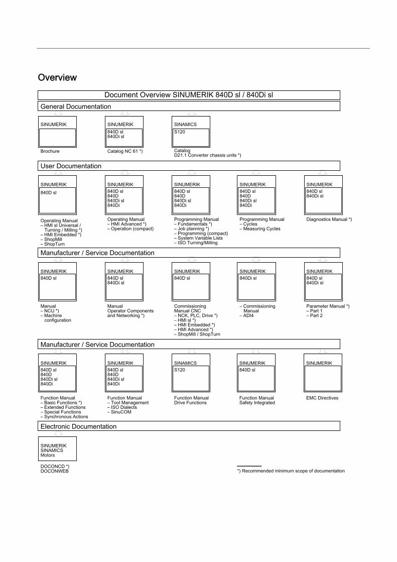
Overview
