mkiv underdeck jib reefing & furling unit 1, 2, 3 · 4656 01/14 preassembly parts 4–5 rigging...
TRANSCRIPT

Please read these instructions carefully before installing, servicing, or operating the equipment. This manual may be modified without notice. See: www.harken.com/manuals for updated versions.
PLEASE SAVE THESE INSTRUCTIONS
MKIV UNDERDECK JIB REEFING & FURLINGUnit 1, 2, 3
Installation Manual – Intended for specialized personnel or expert users4656 01/14
Preassembly Parts 4–5 Rigging Parts Check/Tools 6 Dimensions/Sailmaker's Instructions 7 Stay Length Deductions/Stay Into Foil Options 8Hub Assembly Deck Flange 9 Install Hub Assembly in Bow 10–11 Assemble Drum Components 11 Underdeck Lead Block 12Preassembly Top Foil Length (Unit 1) 13 Top Foil Length (Unit 2) 14 Top Foil Length (Unit 3) 15 Short Top Foil (Unit 1) 16 Short Top Foil (Unit 2) 17 Short Top Foil (Unit 3) 18 Confirm Foil Length 19Assembly Foils/Connectors 20–26 Halyard Swivel 26 Torque Tube Assembly 27 Rod Rigging 28 Attach Turnbuckle/Foils to Boat 29–31 Feeder/Final 32Commissioning Turnbuckle 33–34 Lead Line to Cockpit 35 Halyard Swivel Height/Angle 36 Halyard Restrainer/Tension 37Operation Halyard/Headstay Tension 38 Raise Sails/Storm Sails/Reefing 39–40 Secure Sail 40 Race Conversion 41Maintenance Clean/Lubricate/Inspect 42 Confirm Deck Flange/Tack Swivel Gap 42 Replace Line 42 Storage/Transporting 42 Remove Furler 42Troubleshooting/Warranty
Parts Descriptions
Parts Description
13
2
4
5
6
7
8 9
10
11
12
13
14
15
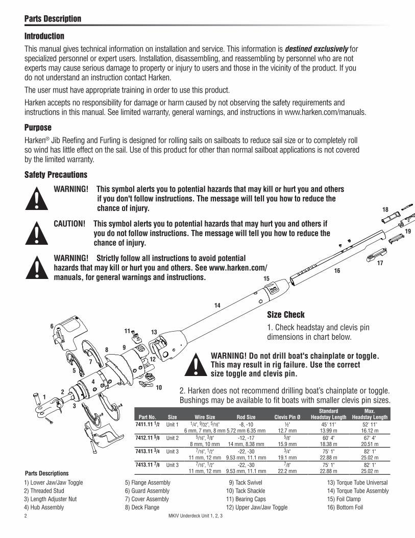
1) Lower Jaw/Jaw Toggle2) Threaded Stud3) Length Adjuster Nut4) Hub Assembly
5) Flange Assembly6) Guard Assembly7) Cover Assembly8) Deck Flange
9) Tack Swivel10) Tack Shackle11) Bearing Caps12) Upper Jaw/Jaw Toggle
13) Torque Tube Universal14) Torque Tube Assembly15) Foil Clamp16) Bottom Foil
1617
18
19
2. Harken does not recommend drilling boat’s chainplate or toggle. Bushings may be available to fit boats with smaller clevis pin sizes.
Part No. Size Wire Size Rod Size Clevis Pin ØStandard
Headstay LengthMax.
Headstay Length7411.11 1/2 Unit 1 1/4", 9/32", 5/16"
6 mm, 7 mm, 8 mm-8, -10
5.72 mm 6.35 mm½"
12.7 mm45' 11"
13.99 m52' 11"
16.12 m7412.11 5/8 Unit 2 5/16", 3/8"
8 mm, 10 mm-12, -17
14 mm, 8.38 mm5/8"
15.9 mm60' 4"
18.38 m67' 4"
20.51 m7413.11 3/4 Unit 3 7/16", 1/2"
11 mm, 12 mm-22, -30
9.53 mm, 11.1 mm3/4"
19.1 mm75' 1"
22.88 m82' 1"
25.02 m7413.11 7/8 Unit 3 7/16", 1/2"
11 mm, 12 mm-22, -30
9.53 mm, 11.1 mm7/8"
22.2 mm75' 1"
22.88 m82' 1"
25.02 m
2 MKIV Underdeck Unit 1, 2, 3
WARNING! Do not drill boat's chainplate or toggle. This may result in rig failure. Use the correct size toggle and clevis pin.
Size Check1. Check headstay and clevis pin dimensions in chart below.
WARNING! Strictly follow all instructions to avoid potential hazards that may kill or hurt you and others. See www.harken.com/manuals, for general warnings and instructions.
WARNING! This symbol alerts you to potential hazards that may kill or hurt you and others if you don't follow instructions. The message will tell you how to reduce the chance of injury.
IntroductionThis manual gives technical information on installation and service. This information is destined exclusively for specialized personnel or expert users. Installation, disassembling, and reassembling by personnel who are not experts may cause serious damage to property or injury to users and those in the vicinity of the product. If you do not understand an instruction contact Harken.
The user must have appropriate training in order to use this product.
Harken accepts no responsibility for damage or harm caused by not observing the safety requirements and instructions in this manual. See limited warranty, general warnings, and instructions in www.harken.com/manuals.
PurposeHarken® Jib Reefing and Furling is designed for rolling sails on sailboats to reduce sail size or to completely roll so wind has little effect on the sail. Use of this product for other than normal sailboat applications is not covered by the limited warranty.
Safety Precautions
CAUTION! This symbol alerts you to potential hazards that may hurt you and others if you do not follow instructions. The message will tell you how to reduce the chance of injury.

Preassembly Sizing Check
23
19
20
21
22
24
25
26
17) Feeder18) Connector Bushing19) Bottom Connector
20) 7' (2.13 m) Foil21) Connector Screws22) Connector Wedge
23) Connector24) Halyard Swivel25) Trim Cap Screws
26) Trim Cap
Unit Part No. A B C D Max E F G Min G Max H Min H Max I J
17411.11 1/2 51/2"
140 mm49/16"
116 mm411/16"
119 mm11/2"
38 mm311/16" 94 mm
25/16" 58 mm
45/8" 117 mm
95/8" 244 mm
105/8" 270 mm
155/8" 397 mm
1/2" 12.7 mm
41/8" 105 mm
27412.11 5/8 65/8"
167 mm51/16"
129 mm51/4"
134 mm113/16" 46 mm
43/16" 106.5 mm
23/4" 70 mm
53/8" 137 mm
115/16" 287 mm
1211/16" 322 mm
189/16" 471 mm
5/8" 15.9 mm
5" 127 mm
37413.11 3/4 83/16"
208 mm61/2"
166 mm63/4"
172 mm21/2"
64 mm57/16"
138.5 mm35/8"
92 mm67/8"
175 mm143/8"
365 mm161/8"
410 mm235/8"
600 mm3/4"
19.1 mm65/16"
160 mm
37413.11 7/8 83/16"
208 mm61/2"
166 mm63/4"
172 mm21/2"
64 mm57/16"
138.5 mm35/8"
92 mm75/16"
186 mm15"
381 mm169/16"
421 mm241/4"
616 mm7/8"
22.2 m 65/16"
160 mm
H
F
G
J
I
D
E
Will Drum Fit in Bow?Note: If length of stud does not allow attachment to chainplate, link plates between chainplate and toggle must be fabricated.
Furler Requires Drained CompartmentHarken’s Underdeck Furler is designed to keep much of the water from entering the bow compartment. Water will drip through the furler during rain or when sailing in heavy weather. Furling compartment must drain.
A B
C
MKIV Underdeck Unit 1, 2, 3 3

Preassembly Parts
Main Components
Torque Tube Assembly
Halyard Swivel
2' (610 mm) Bottom Foil
7' (2.13 m) Foils
Flange Assembly
Cover Assembly
Guard Assembly
Part No.
Description Unit 1 Unit 2 Unit 3-3/4 Unit 3-7/8 Qty
Halyard swivel H-39812 H-39794 H-39392 H-39392 1
Torque Tube Assembly HFG927 HFG928 HFG929 HFG929 1
Hub Assembly HFG923 HFG924 HFG925 HFG926 1
Cover Assembly HFG683 HFG686 HFG689 HFG689 Pair
Flange Assembly HFG684 HFG687 HFG690 HFG690 Pair
Guard Assembly HFG685 HFG688 HFG691 HFG691 Pair
Unit Forward ØMin Break Strength Aft Ø
1 1/4" (6 mm) 2500 lb (1130 kg) 5/16" (8 mm)
2 5/16" (8 mm) 3740 lb (1700 kg) 3/8" (10 mm)
3 3/8" (10 mm) 5000 lb (2270 kg) 7/16" (12 mm)
Line Specifications
Line (Not included with Furler)Note: Line is not included with furler. Drum of unit is smaller to allow it to fit into narrow bow sections. If overlapping sails are used, standard diameter line will fill up drum and jam furler. To prevent this, use small diameter, high strength line at forward end and have a rigger add a cover at aft end where line is handled.
Description Unit Part No. Qty
7' (2.13 m) Foil1
7411.30 6
2' (610 mm) Bottom foil 7411.33 1
7' (2.13 m) Foil2
7412.30 8
2' (610 mm) Bottom foil 7412.33 1
7' (2.13 m) Foil3
7413.30 10
2' (610 mm) Bottom foil 7413.33 1
Foils (Standard Package)
Hub Assembly
4 MKIV Underdeck Unit 1, 2, 3

Bow ShacklesPlastic
Connector Wedges
Foil Screws
Prefeeder
5200 Adhesive
Injector
Bottom Connector
Connectors
Preassembly Parts
Connector Bushings
Trim Cap
Unit 1 Unit 2 Unit 3 (3/4, 7/8)
Description Part No. Qty Part No. Qty Part No. Qty
Connector bushing set HFG295 (12-H-42062/12-H-42063) 1 HFG296
(16-H-42032/16-H-42033) 1 HFG297 (20-H-42073/20-H-42074) 1
Plastic connector wedge set HFG299 (14-H-39625) 1 HFG300
(18-H-39487) 1 HFG324 (22-H-39487) 1
Foil screw set HFG343 (28-HFS1105) 1 HFG348
(36-HFS1106) 1 HFG349 (44-HFS1106) 1
Trim cap set HFG680 (H-37361/H-37362) 1 HFG681
(H-37403/H-37404) 1 HFG682 (H-39751/H-39752) 1
Trim cap screw set HFG629 (3-HFS1126) 1 HFG672
(3-HFS1127) 1 HFG672 (3-HFS1127) 1
Prefeeder 947 1 947 1 947 1
Feeder with screw and tab H-39683 1 H-39559 1 H-39756 1
Injector, 1 oz. 5200 Adhesive HFG725 1 HFG725 1 HFG725 1
Loctite® Blue 833 1 833 1 833 1
Loctite® Red HFG739 2 HFG739 2 HFG739 2
Other Components
Unit 1 Unit 2 Unit 3 (3/4, 7/8)
Description Part No. Qty Size Part No. Qty Size Part No. Qty Size
Connector 7411.31 5 7" (177.8 mm) 7412.31 7 9" (229 mm) 7413.31 9 9.75"(248 mm)
Bottom connector 7411.32 1 10.75" (273 mm) 7412.32 1 13" (330 mm) 7413.32 1 14" (356 mm)
Bow shackle 2110 3 6 mm 2117 3 8 mm 2124 3 10 mm
Description Unit Qty
2.5, 4, 5 mm 1 1 Each
3, 4, 5, 6 mm 2 1 Each
3, 4, 6, 10 mm 3 1 Each
Hex Keys (Supplied)
MKIV Underdeck Unit 1, 2, 3 5
Blue Loctite®
Hex Keys
Red Loctite®
Feeder
Trim Cap Screws

1. Stud/eye turnbuckle components are not included and must be purchased separately. See page 8.2. Rod rigging requires Harken rod adapter stud.3. Order Harken Lead Blocks and one additional 7403 if necessary. Fits 1" (25 mm) stanchions.
Preassembly Rigging Parts Check/Tools
Tools You Will Need
MKIV Furlers are shipped with 3M 5200 adhesive. Use adhesives on dry connectors and foils using the special injection system described in the assembly section. Parts may immediately be exposed to rain. Cure is best at 70F (22C) with 50% humidity. Do not apply at temperatures below 40F (5C) and above 100F (38C).
Although adhesive has not cured it will remain in place on foil joints whether they are left on the ground or raised up on boat. Foils can be raised immediately after assembly and sails fitted.
Note: A small amount of adhesive may bulge out of injection ports. If possible let system sit for a couple days before sailing. If adhesive gets on sails remove using acetone. For faster-curing adhesive, purchase 4200 Fast Cure.
Note: Damaged foils can be repaired. Use a hand-held propane torch to heat joints until foils can be pulled apart.
Adhesive Alert
Unit 1, 2 7404 Lead Block Kit (Sold Separately)
1. Long tape measure 6. Side cutters 11. Center punch 16. Hole saw
2. Short tape measure 7. Rat-tail file 12. Rigging or black tape 17. Deck sealant
3. Power drill 8. Hex Keys (provided) 13. Scissors 18. Box end wrench
4. Drill bits (see chart) 9. Slotted/phillips screwdrivers 14. Metal straight edge 19. 6 mm bolts, nuts and washers
5. Hacksaw 10. Needle-nose pliers 15. Hammer
1013
12
11
8
7
6
5
3
2
1
149
ROD RIGGING Harken Rod Adapter
Stud Required (Sold Separately)
Unit Part No. Thread Ø
17422 -8 1/2" - 20RH
7423 -10 1/2" - 20RH
27424 -12 5/8" - 18RH
7425 -17 5/8" - 18RH
37426 -22 3/4" - 16RH
7427 -30 7/8" - 14RH
Rod Adapter Stud349, 2652
131, 047
Unit Turning Thru-Deck
1 349 131
2 2652 047
3 2600/137/071 HC7981
Recommended Furling Compartment Lead Blocks
UnitDeck
Flange ØHole
Saw Size1 3.7"
(94 mm)3 ¾"
(95 mm)2 4.2"
(106.5 mm)4 ¼"
(110 mm)3 5.45"
(138.5 mm)5 ½"
(140 mm)
16
UnitWrench Size
for Length Adjuster1 7/8"
(22 mm)2 1"
(25 mm)3 1.25"
(32 mm)
18
Use 6 mm bolts and washers to mount deck flange. To figure bolt length, add 3/8" (10 mm) to deck thickness. Minimum thread engagement must be 9mm.
19
17
4
Unit Drill Ø1 1/8" (3 mm), 1/4" (6.25 mm)
2 5/32" (4 mm), 1/4" (6.25 mm)
3 (3/4, 7/8) 5/32" (4 mm), 1/4" (6.25 mm) 15
6 MKIV Underdeck Unit 1, 2, 3

Preassembly Dimensions/Sailmaker's Instructions
Luff LengthNote offsets above and below sail.A shorter luff may be required if a halyard restrainer is necessary (page 37) or a toggle or long toggle assembly is used to raise drum.If luff of sail is not long enough to put halyard swivel near top of headstay foil, a pendant must be added. See page 36.
Tack SetbackFind setback "C" for tack shackle in chart below and modify sail accordingly. Setback is measured to luff tape of sail.
Luff Tape Size
All units require #6 (6/32" or 5 mm) luff tape.
Luff Tape LengthCut off top of luff tape so it is 18 to 24" (450 to 600 mm) below head of sail. This allows head to lag behind rest of sail to help flatten sail. It will also help head to roll more smoothly.Note feeder height and extend bottom of luff tape downward so it is below feeder. This will prevent luff tape from catching in feeder as sail is lowered.
Tack and Head ShacklesMake sure tack and head shackles fit sail rings. The minimum inside dimensions of standard head and tack shackles are:
A
B
Unit Part No. A B C D E F G
1 7411.11 1/2 43/4" 120 mm
7" 177 mm
115/16" 49 mm
1/16" 2 mm — 3713/16"
960 mm35/8"
92 mm
2 7412.11 5/8 55/8" 143 mm
91/8" 231 mm
25/16" 59 mm
1/16" 2 mm
9/16" 14mm
411/16" 1043 mm
41/16" 104 mm
3 7413.11 3/4 75/16" 186 mm
115/8" 296 mm
33/16" 81 mm
1/16" 2 mm
7/16" 11mm
473/16" 1199 mm
53/8" 136 mm
3 7413.11 7/8 75/16" 186 mm
115/8" 296 mm
33/16" 81 mm
1/16" 2 mm — 461/16"
1170 mm513/16"
148 mm
G
E
C
D
F
A
B
MKIV Underdeck Unit 1, 2, 3 7
Unit A B1 11/16" (27 mm) 1/2" (13 mm)
2 13/4" (44 mm) 11/16" (17 mm)
3 17/8" (48 mm) 13/16" (21 mm)
SuncoverSuncovers may be installed on either side of sail. Be sure to match other sails in the customer's inventory.

Preassembly Deduction for Stay Length/Stay Into Foil Options
Use dimensions of Harken toggle below to build stay to correct length.Tip: Turnbuckles should be 1/2 to 2/3rds open to allow shortening for new wire stretch and for fine-tuning mast rake.
1. Swage stud at end of wire.2. Open end of wire and install Norseman or Sta-Lok® stud after foil is assembled.3. Rod adapter nosepiece for Harken rod adapter stud: Threaded nosepiece must have a positive lock as well as adhesive. Use Harken stud with cotter pins. See page 28.
Options for Snaking Stay into Foils
Unit Part No. A B C D1 7411.11 1/2 1/16"
2 mm35/8"
92 mm105/8"
270 mm155/8"
397 mm2 7412.11 5/8 1/16"
2 mm41/8"
104 mm1211/16" 322 mm
189/16" 471 mm
3 7413.11 3/4 1/16" 2 mm
53/8" 136 mm
161/8" 410 mm
235/8" 600 mm
3 7413.11 7/8 1/16" 2 mm
513/16" 148 mm
169/16" 421 mm
241/4" 616 mm
8 MKIV Underdeck Unit 1, 2, 3
CD
B
A
WARNING! Using a threaded nosepiece with only adhesive at the upper rod eye terminal may result in headstay system failure. Make sure there is a mechanical lock.

Assembly Deck Flange
Carefully locate center point in deck to locate deck flange. Line from mast to under deck chainplate must intersect this center point. Mark center fore/aft and athwartships line. Use template to mark four outer holes and center pilot hole. Make sure closer pair of holes is forward.
If deck does not fall within these angles, shims must be made using structural adhesive to avoid excessive pressure on deck and deck bearings.
721/2° – 741/2°
Use 6 mm screws and compound to fasten deck flange. Note: There must be a minimum of 3/8" (9 mm) thread engagement into deck flange.
Note: Deck flange angle matches a stay angle of 731/2° when compared to deck. Angles can vary between 721/2° and 741/2°.
Once you are certain hole is located in line with chainplate and any required shimming is done, drill hole 90° to deck.Make sure hole is just large enough so deck flange bears against deck. It is better to make hole slightly smaller and file opening larger to fit. Use template to mark large hole and bolt holes. Use hole saw to drill deck.Tip: After pilot drill bit clears deck, drill final hole from bottom using pilot hole to line up hole drilled from top. This will prevent glass from chipping.
MKIV Underdeck Unit 1, 2, 3 9
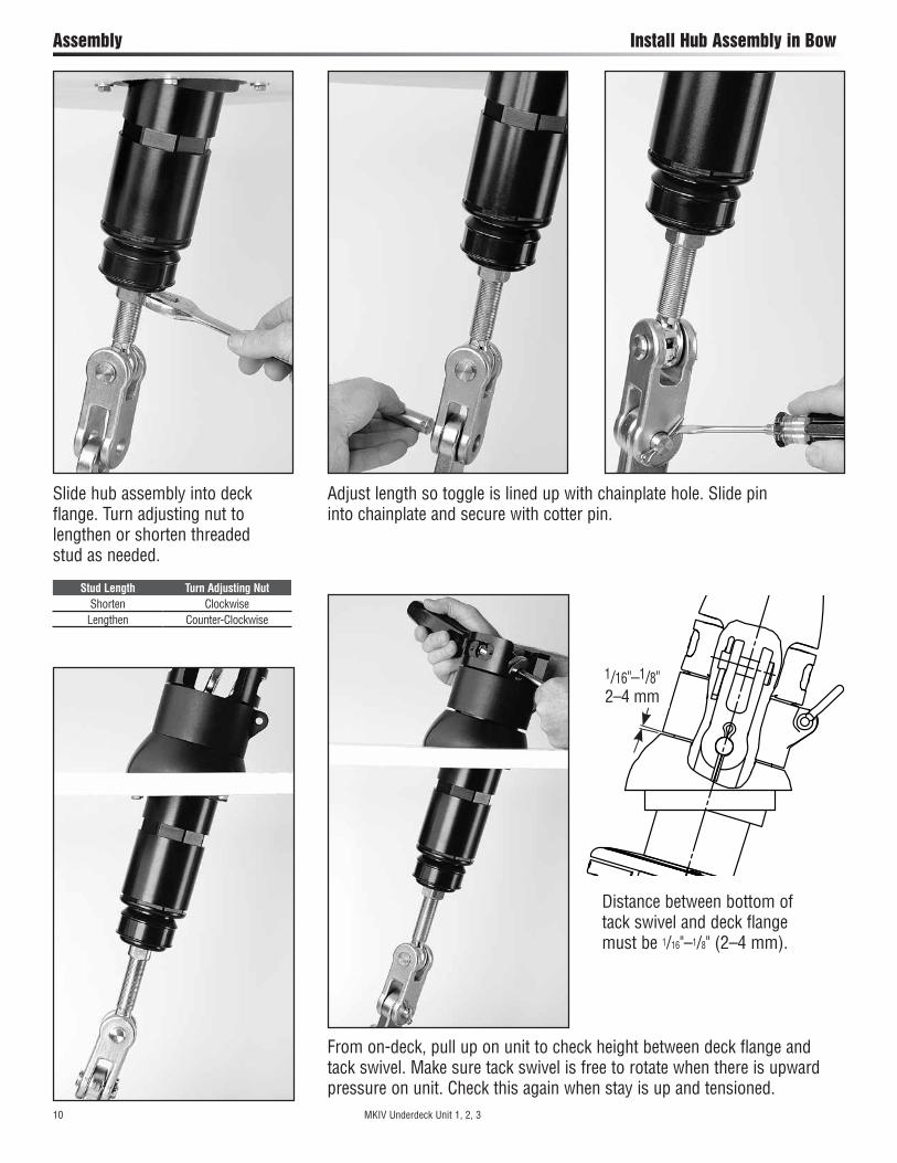
Assembly Install Hub Assembly in Bow
Adjust length so toggle is lined up with chainplate hole. Slide pin into chainplate and secure with cotter pin.
Slide hub assembly into deck flange. Turn adjusting nut to lengthen or shorten threaded stud as needed.
Stud Length Turn Adjusting NutShorten Clockwise
Lengthen Counter-Clockwise
1/16"–1/8" 2–4 mm
From on-deck, pull up on unit to check height between deck flange and tack swivel. Make sure tack swivel is free to rotate when there is upward pressure on unit. Check this again when stay is up and tensioned.
Distance between bottom of tack swivel and deck flange must be 1/16"–1/8" (2–4 mm).
10 MKIV Underdeck Unit 1, 2, 3
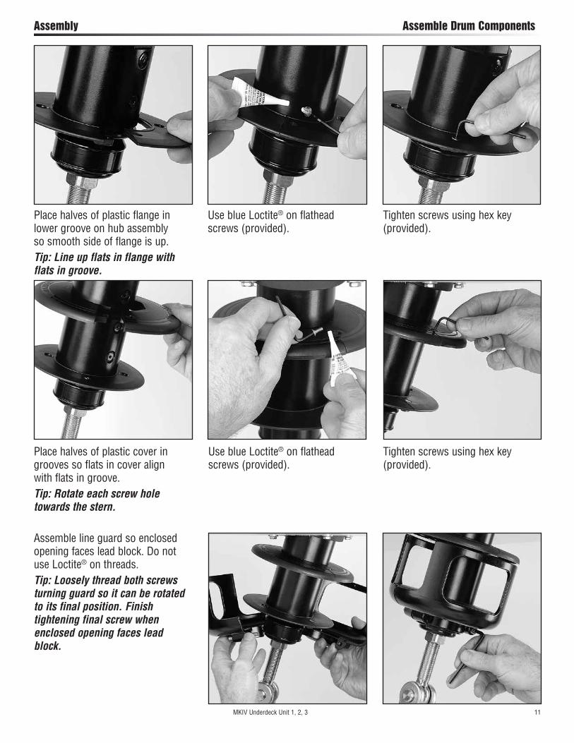
Assembly Assemble Drum Components
Place halves of plastic flange in lower groove on hub assembly so smooth side of flange is up.Tip: Line up flats in flange with flats in groove.
Place halves of plastic cover in grooves so flats in cover align with flats in groove.Tip: Rotate each screw hole towards the stern.
Use blue Loctite® on flathead screws (provided).
Use blue Loctite® on flathead screws (provided).
Assemble line guard so enclosed opening faces lead block. Do not use Loctite® on threads.Tip: Loosely thread both screws turning guard so it can be rotated to its final position. Finish tightening final screw when enclosed opening faces lead block.
Tighten screws using hex key (provided).
Tighten screws using hex key (provided).
MKIV Underdeck Unit 1, 2, 3 11

Assembly Underdeck Lead Block
Mount lead block so that line exits furler at 90° to line of headstay as shown. Remember block will split angle and raise up slightly under load. Mount thru-deck block. You may want to angle it toward stanchion block.
Mount thru-deck block. You may want to angle it toward stanchion lead block.
12 MKIV Underdeck Unit 1, 2, 3
90°

UNIT
1
Length Chart
Dimensions Inches mmA Center of Pin to Bottom of TerminalB Bottom of Terminal to Top of Foil .50 13C Top Foil Length
D Number of Foils ________ x 84" (2133.6 mm)
E Bottom Foil 24 610F Bottom of Foil to Jaw/Jaw Toggle 15.25 387
Pin-to-Pin Length
Measure A and add to this chart and length chart below
Inches mm
A
B .50 13
E 24 610
F 15.25 387
Total A+B+E+F
Make sure upper measurement points of A and pin-to-pin are the same.
1 Pin-to-Pin Length
2 Subtract ABEF –
3 Result (Pin-to-Pin – ABEF)
4 Subtract D –To find “D” pick number from chart below that is clos-est to, but not greater than total from step 3.
Inches mm3 x 84 = 252 4 x 84 = 336 5 x 84 = 420 6 x 84 = 504 7 x 84 = 588 8 x 84 = 672
3 x 2133.6 = 6400.8 4 x 2133.6 = 8534.4 5 x 2133.6 = 10668 6 x 2133.6 = 12801.6 7 x 2133.6 = 14935.2 8 x 2133.6 = 17068.8
Example–If result from Step 3 is:500 inches “D” = 420 inches 12,000 mm
“D” = 10,668 mm5 Result (C) Top Foil Length
After completing worksheet above fill in A, C and D below. Add “A” through “F” to confirm total equals your pin-to-pin measurement.
Length Check
Alternate Measurement
PointA
TOP FOIL LENGTH WORKSHEET
Preassembly Unit 1—Top Foil Length
A
C
D
E
F
Pin to
Pin
B
MKIV Underdeck Unit 1 13
Pin to
Pin

UNIT
2Preassembly Unit 2—Top Foil Length
Length Chart
Dimensions Inches mmA Center of Pin to Bottom of TerminalB Bottom of Terminal to Top of Foil .63 16C Top Foil Length
D Number of Foils ________ x 84" (2133.6 mm)
E Bottom Foil 24 610F Bottom of Foil to Jaw/Jaw Toggle 18.45 469
Pin-to-Pin Length
Measure A and add to this chart and length chart below
Inches mm
A
B .63 16
E 24 610
F 18.45 469
Total A+B+E+F
Make sure upper measurement points of A and pin-to-pin are the same.
1 Pin-to-Pin Length
2 Subtract ABEF –
3 Result (Pin-to-Pin – ABEF)
4 Subtract D –To find “D” pick number from chart below that is clos-est to, but not greater than total from step 3.
Inches mm5 x 84 = 420 6 x 84 = 504 7 x 84 = 588 8 x 84 = 672 9 x 84 = 756
5 x 2133.6 = 10668 6 x 2133.6 = 12801.6 7 x 2133.6 = 14935.2 8 x 2133.6 = 17068.8 9 x 2133.6 = 19202.4
Example–If result from Step 3 is:500 inches “D” = 420 inches 12,000 mm
“D” = 10,668 mm5 Result (C) Top Foil Length
After completing worksheet above fill in A, C and D below. Add “A” through “F” to confirm total equals your pin-to-pin measurement.
Length Check
Alternate Measurement
PointA
TOP FOIL LENGTH WORKSHEET
A
C
D
E
F
Pin to
Pin
B
14 MKIV Underdeck Unit 2
Pin to
Pin

UNIT
3 ( 3
/4, 7
/8)
Length Chart
Dimensions Inches mmA Center of Pin to Bottom of TerminalB Bottom of Terminal to Top of Foil 1 25C Top Foil Length
D Number of Foils ________ x 84" (2133.6 mm)
E Bottom Foil 24 610F Unit 3-3/4–Bottom of Foil to Jaw/Jaw Toggle 24 610F Unit 3-7/8–Bottom of Foil to Jaw/Jaw Toggle 23.4 594
Pin-to-Pin Length
Measure A and add to this chart and length chart below
Inches mm
A
B 1 25
E 24 610
F 23.4 594
Total A+B+E+F
Make sure upper measurement points of A and pin-to-pin are the same.
1 Pin-to-Pin Length
2 Subtract ABEF –
3 Result (Pin-to-Pin – ABEF)
4 Subtract D –To find “D” pick number from chart below that is clos-est to, but not greater than total from step 3.
Inches mm7 x 84 = 588 8 x 84 = 672 9 x 84 = 756
10 x 84 = 840 11 x 84 = 924
7 x 2133.6 = 14935.2 8 x 2133.6 = 17068.8 9 x 2133.6 = 19202.4 10 x 2133.6 = 21336 11 x 2133.6 = 23470
Example–If result from Step 3 is:800 inches “D” = 756 inches 20,000 mm
“D” = 19,202 mm5 Result (C) Top Foil Length
After completing worksheet above fill in A, C and D below. Add “A” through “F” to confirm total equals your pin-to-pin measurement.
Length Check
Alternate Measurement
PointA
TOP FOIL LENGTH WORKSHEET
A
C
D
E
F
Pin to
Pin
B
Preassembly Unit 3—Top Foil Length
MKIV Underdeck Unit 3 15
Pin to
Pin

16 MKIV Underdeck Unit 1
Preassembly Unit 1—Short Top Foil
If top foil is shorter than 7" (177.8 mm), use one of the following special techniques to ensure sufficient bearing surface for the foil in the area of the halyard swivel.
21/2
(64
mm
) 2"
(51
mm
) 11
/2" (3
8 m
m)
1" (2
5 m
m)
7" (178 mm) No special treatment required.
7" (1
78 m
m)
6"–5" (152–130 mm) Do not use plastic bushing above top connector.
6"–5
" (15
0–13
0 m
m)
41/2"–4" (115–102 mm) Do not use plastic bushing above top connector. Shorten top of connector and if necessary shorten trim cap.
41/2"
–4" (
115–
100
mm
)
31/2"–3" (90–75 mm) Do not use plastic bushing above top connector. Cut connector right at cross formed by glue dispersion channels. Use single foil screw in top foil only.
31/2"
- 3"
(90
- 75
mm
)
Under 1" (25 mm) Eliminate top foil and run foil higher in torque tube.
Und
er 1
" (25
mm
)Top Foil
Length from Worksheet
1. Initial top foil cut length
2. Cut through middle hole in top foil.*
3. Shorten full length adjoining foil by cutting through middle hole.*
4. Shorten connector
5. Shorten trim cap
Resulting Top Foil Length Length
21/2" (64 mm)
57/8" (149 mm)
41/8" (105 mm)
31/2" (89 mm) No
2" (51 mm)
53/8" (137 mm)
35/8" (92 mm)
31/2" (89 mm) No
11/2" 38 mm)
47/8" (124 mm)
31/8" (79 mm)
31/2" (89 mm) Yes
1" (25 mm)
43/8" (111 mm)
25/8" (67 mm)
31/4" (83 mm) Yes
21/2"–1" (64–25 mm) Shorten top foil and adjoining full length foil so two screws are used to assemble joint instead of four. Do not use plastic bushings above top connector.
*To allow for saw cut, position blade so upper half of middle hole is preserved.
Cut-Offs – Do Not Use
Cut-Offs Do Not Use
Cut-Offs Do Not Use
Cut-Offs Do Not Use
UNIT
1

Preassembly Unit 2—Short Top Foil
If top foil is shorter than 811/16" (221 mm), use one of the following special techniques to ensure sufficient bearing surface for the foil in the area of the halyard swivel.
3" (7
6 m
m)
21/2"
(64
mm
) 2"
(51
mm
) 11
/2" (3
8 m
m)
1" (2
5 m
m)
811/16" (221 mm) No special treatment required.
811 /1
6" (2
21 m
m)
85/8" – 63/8" (219–162 mm) Do not use plastic bushing above top connector.
85/8"
–63 /8
" (21
9–16
2 m
m)
6"–51/2" (152–140 mm) Do not use plastic bushing above top connector. Shorten top of connector and if necessary shorten trim cap.
6"–5
1 /2" (
152–
140
mm
)
51/4"–35/8" (133–92 mm) Do not use plastic bushing above top connector. Cut connector right at cross formed by glue dispersion channels. Use single foil screw in top foil only.
51/4"
–35 /8
" (13
3–92
mm
)
Under 1" (25 mm) Eliminate top foil and run foil higher in torque tube.
Und
er 1
" (25
mm
)Top Foil
Length from Worksheet
1. Initial top foil cut length
2. Cut through middle hole in top foil.*
3. Shorten full length adjoining foil by cutting through middle hole.*
4. Shorten connector
5. Shorten trim cap
Resulting Top Foil Length Length
3" (76 mm)
71/4" (184 mm)
51/8" (130 mm)
41/2" (114 mm) No
21/2" (64 mm)
63/4" (172 mm)
45/8" (117 mm)
41/2" (114 mm) No
2" (51 mm)
61/4" (159 mm)
41/8" (105 mm)
41/2" (114 mm) No
11/2" (38 mm)
53/4" (146 mm)
35/8" (92 mm)
33/4" (95 mm) Yes
1" (25 mm)
51/4" (133 mm)
31/8" (79 mm)
33/4" (95 mm) Yes
3"–1" (76–25 mm) Shorten top foil and adjoining full length foil so two screws are used to assemble joint instead of four. Do not use plastic bushings above top connector.
*To allow for saw cut, position blade so upper half of middle hole is preserved.
Cut-Offs – Do Not Use
Cut-Offs Do Not Use
Cut-Offs Do Not Use
Cut-Offs Do Not Use
Cut-Off Do Not Use
MKIV Underdeck Unit 2 17
UNIT
2

18 MKIV Underdeck Unit 3
Preassembly Unit 3—Short Top Foil
If top foil is shorter than 93/4" (248 mm), use one of the following special techniques to ensure sufficient bearing surface for the foil in the area of the halyard swivel.
31/2"
(89
mm
) 3"
(76
mm
) 21
/2" (6
4 m
m)
2" (5
1 m
m)
11/2"
(38
mm
)
93/4" (248 mm) No special treatment required.
93/4"
(248
mm
)
95/8"–71/8" (244–181 mm) Do not use plastic bushing above top connector.
95/8"
–71 /8
" (24
4–18
1 m
m)
7"–51/2" (178–140 mm) Do not use plastic bushing above top connector. Shorten top of connector and if necessary shorten trim cap.
7"–5
1 /2" (
178–
140
mm
)
53/8"–4" (137–102 mm) Do not use plastic bushing above top connector. Cut connector right at cross formed by glue dispersion channels. Use single foil screw in top foil only.
53/8"
–4" (
137–
102
mm
)
Under 11/2" (38 mm) Eliminate top foil and run foil higher in torque tube.
Und
er 1
1 /2" (
38 m
m)
Top Foil Length from Worksheet
1. Initial top foil cut length
2. Cut through middle hole in top foil.*
3. Shorten full length adjoining foil by cutting through middle hole.*
4. Shorten connector
5. Shorten trim cap
Resulting Top Foil Length Length
31/2" (89 mm)
69/16" (167 mm)
5" (127 mm)
47/8" (124 mm) No
3" (76 mm)
61/16" (154 mm)
41/2" (114 mm)
47/8" (124 mm) No
21/2" (64 mm)
69/16" (167 mm)
4" (102 mm)
47/8" (124 mm) No
2" (51 mm)
51/16" (129 mm)
31/2" (89 mm)
43/8" (111 mm) Yes
11/2" (38 mm)
49/16" (116 mm)
3" (76 mm)
33/4" (95 mm) Yes
31/2"–11/2" (89–38 mm) Shorten top foil and adjoining full length foil so two screws are used to assemble joint instead of four. Do not use plastic bushings above top connector.
*To allow for saw cut, position blade so upper half of middle hole is preserved.
Cut-Offs – Do Not Use
Cut-Offs Do Not Use
Cut-Offs Do Not Use
Cut-Offs Do Not Use
Cut-Off Do Not Use
UNIT
3

Preassembly Confirm Foil Length
Line up bottom foil so foil clamp is just above or below center of notches in bottom foil.
Confirm foil length by laying foils along-side stay with turnbuckle components and torque tube assembly. Pull stay out straight. Line up turnbuckle eye with a point just above bottom of torque tube assembly. This point will line up with Jaw/Jaw toggle pin. See chart above right.
Note: Position top foil so that with top cap the foil will ride 5/8" (16 mm) below terminal. If wire fitting at top of stay is swage, foil must ride just below shoulder of swage. Mark cut line on foil. Wrap tape around foil as a guide so cut is straight.
Unit PinJaw/Jaw Toggle Pin to Bottom of
Torque Tube Assembly1 1/2" (12.7 mm) 7/16" (11 mm)2 5/8"(15,9 mm) 1/4" (6 mm)3 3/4" (19.1 mm) 5/8"(16 mm)3 7/8"(22.2 mm) 1" (25 mm)
MKIV Underdeck Unit 1, 2, 3 19

Assembly Top Foil
Deburr inside edge using rat-tail file.
Cut foil to length using hacksaw.
Prepare top foil for drilling.Tip: Mark top foil to distinguish from cutoff piece.Scribe line on top of foil to mark drill holes. Lay top foil alongside cutoff piece and use a flat metal object (i.e. metal ruler) to scribe top line of foil.
20 MKIV Underdeck Unit 1, 2, 3
Assembly Top Foil
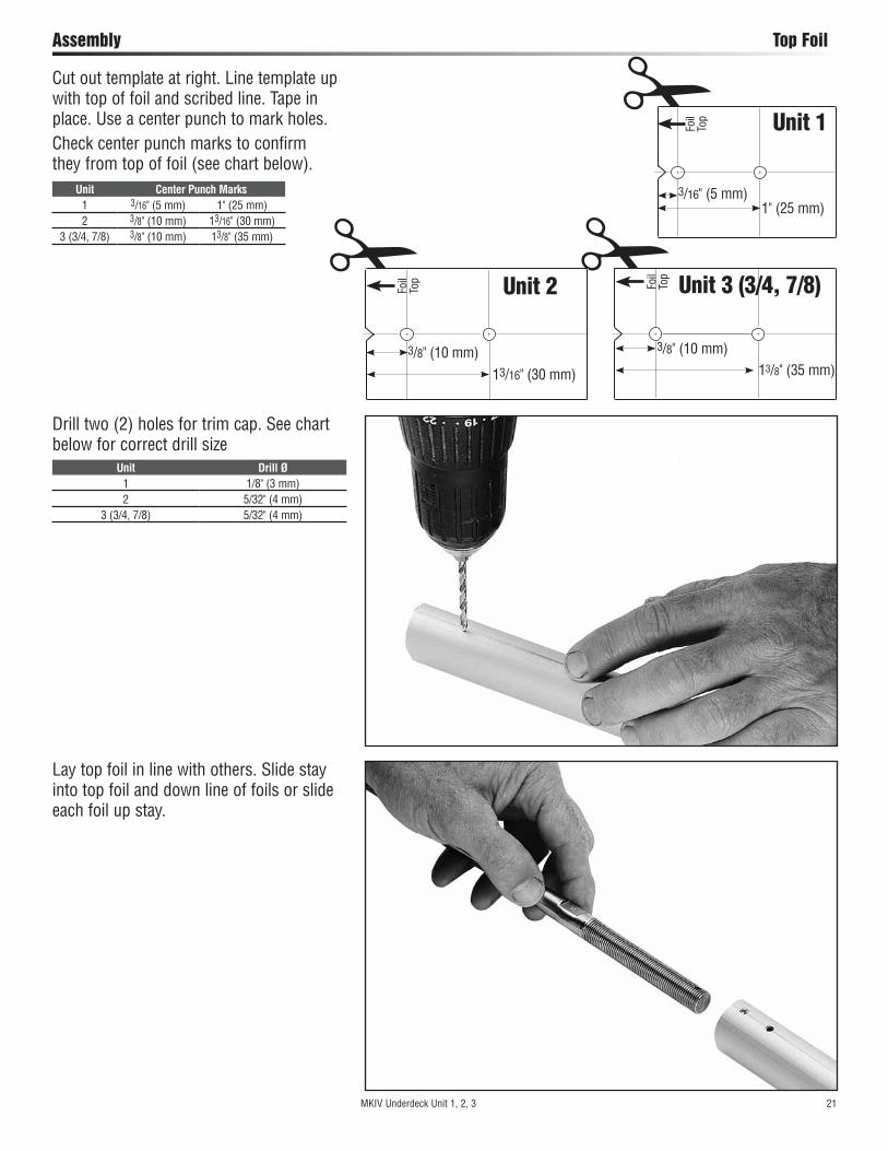
Cut out template at right. Line template up with top of foil and scribed line. Tape in place. Use a center punch to mark holes.Check center punch marks to confirm they from top of foil (see chart below).
Drill two (2) holes for trim cap. See chart below for correct drill size
Lay top foil in line with others. Slide stay into top foil and down line of foils or slide each foil up stay.
Foil
Top!
13/8" (35 mm)
3/8" (10 mm)
3/16" (5 mm)1" (25 mm)
Foil
Top!
Unit 1
Foil
Top
13/16" (30 mm)
3/8" (10 mm)
!Unit 2 Unit 3 (3/4, 7/8)
Unit Drill Ø1 1/8" (3 mm)2 5/32" (4 mm)
3 (3/4, 7/8) 5/32" (4 mm)
Unit Center Punch Marks1 3/16" (5 mm) 1" (25 mm)2 3/8" (10 mm) 13/16" (30 mm)
3 (3/4, 7/8) 3/8" (10 mm) 13/8" (35 mm)
MKIV Underdeck Unit 1, 2, 3 21

Assembly Top Foil
Place halves of plastic bushings on stay so hooked part of longer section faces out.Tip: With foil screw holes up as shown below, place longer half of bushing with hook on upper half.
Install trim cap. Place each side over wire.
Push trim cap into foil to start, then tap in using hammer.Install trim cap screws.
22 MKIV Underdeck Unit 1, 2, 3

Assembly Top Foil/Connectors
Slip connector on wire, mating hook of plastic bushing with connector.
MKIV Underdeck Unit 1, 2, 3 23
Put a drop of red Loctite® into screw holes.

Hold plastic wedge in place with thumb as you insert into foil. Line foil holes with connector screw holes.
Assembly Foils/Connectors
24 MKIV Underdeck Unit 1, 2, 3
Loading Injector with Adhesive
Tip: In cooler weather, keep sealed adhesive in pocket to keep warm. Use instructions below to fill injector less than half way; you will only use a small amount of adhesive. Refill if needed but do not keep open sealant for long periods. Use adhesive within 3 hours.Use cap of adhesive to break seal. Remove injector tip cap and plunger. Hold injector at an angle with applicator tip facing down. Squeeze adhesive into tube so lower half of injector is full as shown. Keep tip free of sealant to let air inside. Adhesive in
lower half
Start plunger into injector and immediately hold upright so plunger is down and applicator tip is up.As sealant runs down towards plunger an air pocket will form near tip. Push plunger to evacuate air. You are now ready to begin injecting adhesive.
Assembly Foils/Connectors
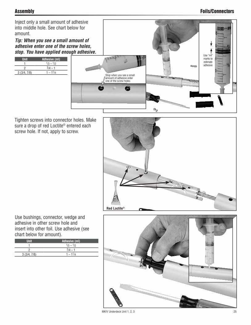
Use bushings, connector, wedge and adhesive in other screw hole and insert into other foil. Use adhesive (see chart below for amount).
Inject only a small amount of adhesive into middle hole. See chart below for amount.Tip: When you see a small amount of adhesive enter one of the screw holes, stop. You have applied enough adhesive.
Use “ml” marks to estimate adhesive
Stop when you see a small amount of adhesive enter one of the screw holes.
Unit Adhesive (ml)1 1/3 – 1/22 3/4 – 1
3 (3/4, 7/8) 1 – 11/4
Unit Adhesive (ml)1 1/3 – 1/22 3/4 – 1
3 (3/4, 7/8) 1 – 11/4
MKIV Underdeck Unit 1, 2, 3 25
Tighten screws into connector holes. Make sure a drop of red Loctite® entered each screw hole. If not, apply to screw.
Red Loctite®

Continue assembly. Use bottom connector to assemble bottom foil.
Slide halyard swivel onto foil above feeder window. Make sure taller “half” is up as shown.
Assembly Bottom Foil/Connectors/Halyard Swivel
26 MKIV Underdeck Unit 1, 2, 3
Continue installing connectors and wedges. Make sure to use red Loctite® in screw holes.
Red Loctite®
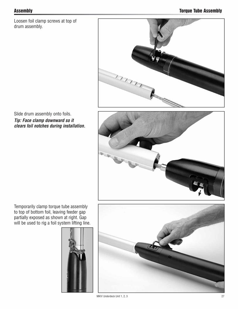
Loosen foil clamp screws at top of drum assembly.
Slide drum assembly onto foils.Tip: Face clamp downward so it clears foil notches during installation.
Assembly Torque Tube Assembly
MKIV Underdeck Unit 1, 2, 3 27
Temporarily clamp torque tube assembly to top of bottom foil, leaving feeder gap partially exposed as shown at right. Gap will be used to rig a foil system lifting line.

RO
D R
IGG
ING
Insert two cotter pins and spread. Clean excess Loctite® from terminal body using special care to ensure that there is no red Loctite® on threaded stud.
Assembly Rod Rigging: Rod Adapter Stud
Apply a few drops of red Loctite® to threads of nosepiece.Screw main threaded stud portion onto bronze nosepiece until flats align with two cotter pin holes in terminal body.Tip: Turn nosepiece completely into threaded stud portion. Flats will be close and may only require a small half turn to align with cotter pin holes.
28 MKIV Underdeck Unit 1, 2, 3

Washer
Assembly Attach Turnbuckle/Foil System to Boat
Thread turnbuckle and threaded eye to stud protruding from foil. Assemble turnbuckle.Note: If using Sta-Lok® or Norseman® stud, you must use a washer above stud as shown below.
Taking care not to lose parts, remove bearing caps from drum assembly.Tip: Rig a large round plastic wash basin below furler to catch any parts that may be lost overboard. MKIV Underdeck Unit 1, 2, 3 29
Assembly Attach Turnbuckle/Foil System to Boat
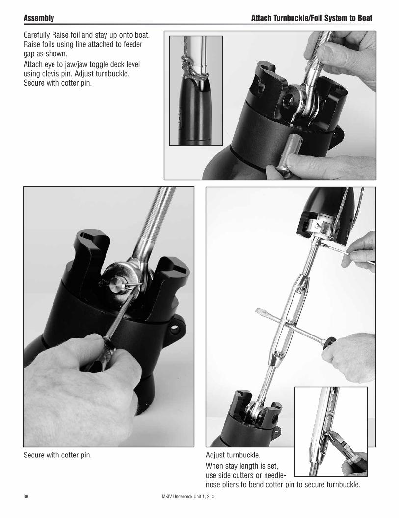
Carefully Raise foil and stay up onto boat. Raise foils using line attached to feeder gap as shown.Attach eye to jaw/jaw toggle deck level using clevis pin. Adjust turnbuckle. Secure with cotter pin.
Adjust turnbuckle. When stay length is set, use side cutters or needle- nose pliers to bend cotter pin to secure turnbuckle.
Secure with cotter pin.
30 MKIV Underdeck Unit 1, 2, 3
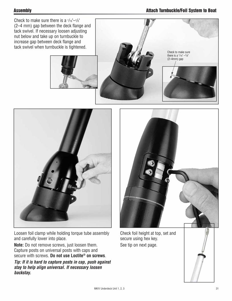
Check foil height at top, set and secure using hex key.See tip on next page.
Assembly Attach Turnbuckle/Foil System to Boat
Check to make sure there is a 1/16"–1/8" (2–4 mm) gap between the deck flange and tack swivel. If necessary loosen adjusting nut below and take up on turnbuckle to increase gap between deck flange and tack swivel when turnbuckle is tightened.
Check to make sure there is a 1/16" –1/8" (2–4mm) gap
Loosen foil clamp while holding torque tube assembly and carefully lower into place.Note: Do not remove screws, just loosen them. Capture posts on universal posts with caps and secure with screws. Do not use Loctite® on screws.Tip: If it is hard to capture posts in cap, push against stay to help align universal. If necessary loosen backstay.
MKIV Underdeck Unit 1, 2, 3 31

Tip: Do not remove foil clamp screws to adjust foil. Loosen screws, hold foils and bring clamp away from foils. Adjust and reclamp.
Assembly Feeder/Final
Slide halyard swivel above feeder. Place feeder in foil recess. Push screw down so tab catches under foil.
Tighten screw.Note: Screw will turn with some difficulty. It is plastic coated to prevent loosening due to vibration.Important! When removing feeder, loosen screw no more than one full turn. Slide screw up and remove feeder.
32 MKIV Underdeck Unit 1, 2, 3

Commissioning Turnbuckle on Boat
MKIV Underdeck Unit 1, 2, 3 33
Have extra cotter pins on hand to replace used ones at base of unit and for turnbuckle.Hold foils and loosen torque tube screws until you can pull clamp part way out in order to lower foils.Lower foils.Rig a screw catcher. Remove screws holding bearing caps and remove taking care to not lose parts.
Loosen, but do not remove
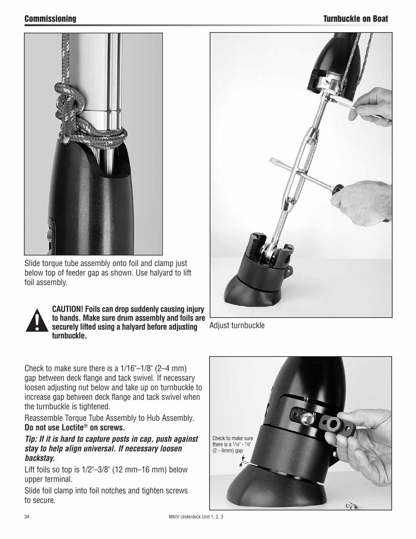
Slide torque tube assembly onto foil and clamp just below top of feeder gap as shown. Use halyard to lift foil assembly.
Commissioning Turnbuckle on Boat
Adjust turnbuckle
Check to make sure there is a 1/16"–1/8" (2–4 mm) gap between deck flange and tack swivel. If necessary loosen adjusting nut below and take up on turnbuckle to increase gap between deck flange and tack swivel when the turnbuckle is tightened.Reassemble Torque Tube Assembly to Hub Assembly. Do not use Loctite® on screws.Tip: If it is hard to capture posts in cap, push against stay to help align universal. If necessary loosen backstay.Lift foils so top is 1/2"–3/8" (12 mm–16 mm) below upper terminal.Slide foil clamp into foil notches and tighten screws to secure.
Check to make sure there is a 1/16" - 1/8" (2 - 4mm) gap
34 MKIV Underdeck Unit 1, 2, 3
CAUTION! Foils can drop suddenly causing injury to hands. Make sure drum assembly and foils are securely lifted using a halyard before adjusting turnbuckle.

Commissioning Lead Line to Cockpit
MKIV Underdeck Unit 1, 2, 3 35
Note: As furling line lead changes, make sure line doesn’t chafe against line guard. Rotate line guard if necessary.
Drum Empty (sail furled)
Drum Full (sail unfurled)
Position Forward Lead Block so line enters drum at right angles to headstay and centers vertically in opening. Install so line is inside stanchion.Correct block position is critical to even line spooling and ease of furling.
7401 Forward Lead Block
Install 7403 Outboard Stanchion Blocks so line is outside stanchions.Number and placement of leads depends on boat length and number/configuration of stanchions.
7403 Outboard Stanchion Blocks
Mount 7402 Ratchet Stanchion Block as furthest-aft lead to prevent line overrides in drum when unfurling.Position ratchet block so line turns at least 90°.Install so line is inside stanchion.Lead line through block so ratchet makes clicking sound when pulling line to furl sail. Tip: Make sure ratchet switch is in “ON” position. If there is no clicking sound, lead line through block in opposite direction.Lead line to Furling Line Cleat in cockpit.
7402 Ratchet Stanchion Block
Install so line is angled as shown. Use #10 (5 mm) fasteners.
HCP168 Furling Line Cleat
Run line through enclosed window in guard and into hole in bottom plate of spool. Tie a small overhand knot and pull it up under drum assembly.
Mount Lead BlocksFurling line can be led down either side of boat. If boat is in slip, consider mounting opposite dock. Remove four screws on stanchion blocks. Clamp blocks to stanchions. See instructions below. Tip: Start all four screws before tightening.
STERN
BOW
7401FORWARD
LEADBLOCK
7403OUTBOARDSTANCHION
BLOCK
WARNING! Lead line through enclosed window. If line is led through opening between two enclosed windows it can ride above lineguard and jam furler which can cause loss of control of boat.
Note location of sun cover. Charge system by rotating furler to wrap line on drum.Tip: Sun cover to starboard—turn clockwise to charge. Sun cover to port—turn counter-clockwise. Tension line while charging.
Enclosed Window
90°
7402RATCHET
STANCHION BLOCK
349 – Unit 1, 2 2652 – Unit 3
088 – Unit 1, 2 131 – Unit 3
7403OUTBOARDSTANCHION
BLOCK
Commissioning Halyard: Swivel Height/Lead Angle
36 MKIV Underdeck Unit 1, 2, 3
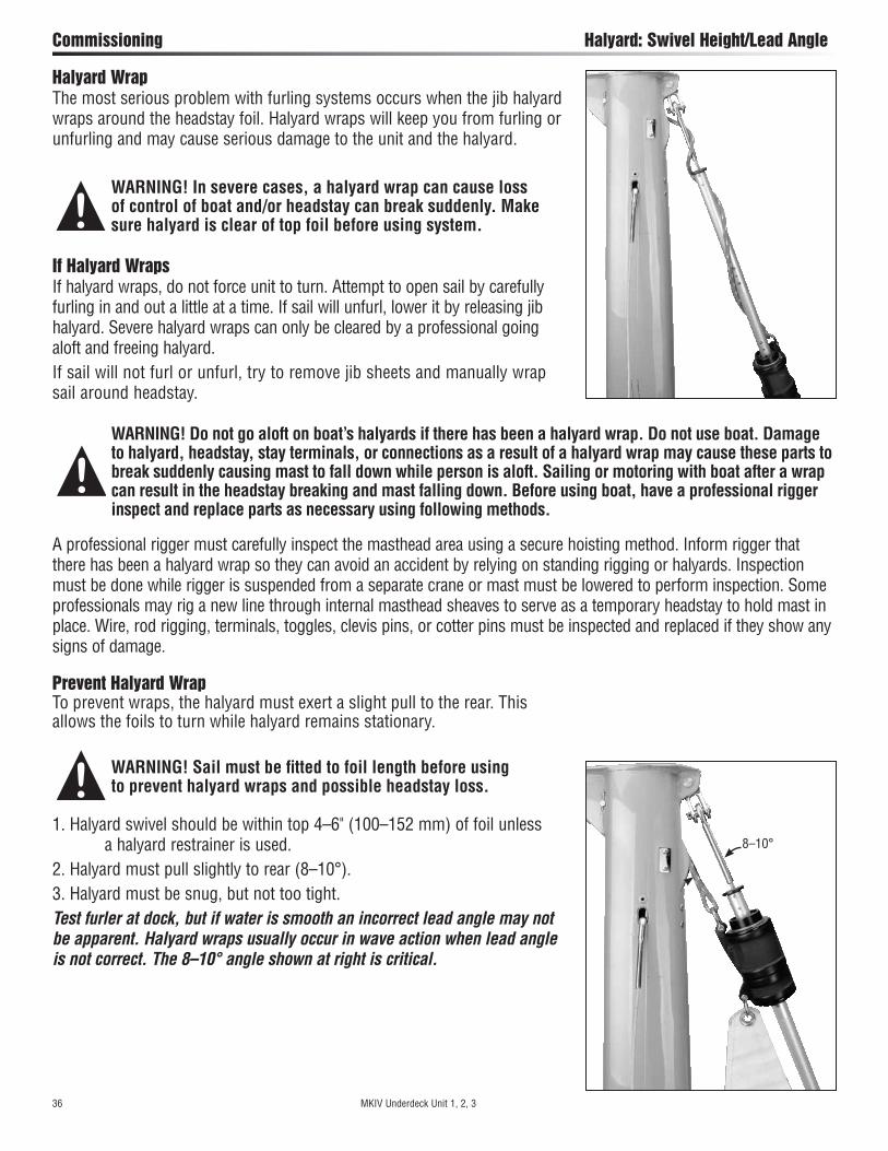
1. Halyard swivel should be within top 4–6" (100–152 mm) of foil unless a halyard restrainer is used.2. Halyard must pull slightly to rear (8–10°).3. Halyard must be snug, but not too tight.Test furler at dock, but if water is smooth an incorrect lead angle may not be apparent. Halyard wraps usually occur in wave action when lead angle is not correct. The 8–10° angle shown at right is critical.
Prevent Halyard WrapTo prevent wraps, the halyard must exert a slight pull to the rear. This allows the foils to turn while halyard remains stationary.
WARNING! Sail must be fitted to foil length before using to prevent halyard wraps and possible headstay loss.
Halyard WrapThe most serious problem with furling systems occurs when the jib halyard wraps around the headstay foil. Halyard wraps will keep you from furling or unfurling and may cause serious damage to the unit and the halyard.
WARNING! In severe cases, a halyard wrap can cause loss of control of boat and/or headstay can break suddenly. Make sure halyard is clear of top foil before using system.
A professional rigger must carefully inspect the masthead area using a secure hoisting method. Inform rigger that there has been a halyard wrap so they can avoid an accident by relying on standing rigging or halyards. Inspection must be done while rigger is suspended from a separate crane or mast must be lowered to perform inspection. Some professionals may rig a new line through internal masthead sheaves to serve as a temporary headstay to hold mast in place. Wire, rod rigging, terminals, toggles, clevis pins, or cotter pins must be inspected and replaced if they show any signs of damage.
WARNING! Do not go aloft on boat’s halyards if there has been a halyard wrap. Do not use boat. Damage to halyard, headstay, stay terminals, or connections as a result of a halyard wrap may cause these parts to break suddenly causing mast to fall down while person is aloft. Sailing or motoring with boat after a wrap can result in the headstay breaking and mast falling down. Before using boat, have a professional rigger inspect and replace parts as necessary using following methods.
If Halyard WrapsIf halyard wraps, do not force unit to turn. Attempt to open sail by carefully furling in and out a little at a time. If sail will unfurl, lower it by releasing jib halyard. Severe halyard wraps can only be cleared by a professional going aloft and freeing halyard.If sail will not furl or unfurl, try to remove jib sheets and manually wrap sail around headstay.
8–10°

Commissioning Halyard: Restrainer/Tension
MKIV Underdeck Unit 1, 2, 3 37
Halyard Deflector/Halyard RestrainerTo prevent wraps, jib halyard must pull slightly to rear. On most boats, halyard lead angle is acceptable if halyard swivel is raised to top of foil.On some boats halyard sheaves are located too close to headstay and a Halyard Deflector or Halyard Restrainer must be used.Halyard restrainers should be used only when required by masthead geometry. Restrainers tend to limit sail luff length and may cause problems if not installed properly.If your boat needs a Halyard Deflector, use Part No. 7302 or a Halyard Restrainer, use Harken Part No. 944.Restrainer should be mounted as high as possible on face of mast. Position restrainer so that foils will not hit it when under load.The restrainer should deflect halyard as little as possible or you may experience difficulty in tensioning sail luff, friction when furling, and possible damage to foils. To decrease deflection angles, shorten sail luff.Tip: Boats used in charter service should have a halyard restrainer, regardless of masthead geometry.
Halyard TensionThe jib halyard should be firm, but not too tight.Tip: The luff foil system supports sail along its length so halyard tension is used only to shape sails, not to support them. Use enough halyard tension to remove some wrinkles along luff of sail. Do not tension halyard enough to cause vertical wrinkles in luff of sail. Tension to adjust position of draft in sail to suit sailing conditions. Halyard should be firm but not tight. If in doubt, release halyard tension. To protect sail, ease halyard when boat is not in use.
PendantsIf the your sail luff is not long enough to position halyard swivel high enough to create an 8–10° angle as shown, you must add a pendant. Pendants should be made of plastic-coated wire and be permanently attached so sail height will be correct. Adjustable- length pendants are not acceptable, as they might not be adjusted correctly during a sail change.1. Raise sail, but do not attach tack shackle. 2. Position halyard swivel correctly near top of headstay. 3. Secure halyard. 4. Tie a piece of rope to sail tack. 5. Lead line through tack shackle on furling drum. 6. Tension sail. 7. Measure distance from tack shackle to sail tack and permanently attach pendant of this length to head of sail. 8. Repeat procedure for every jib in your sail inventory.
Halyard Restrainer
Halyard Deflector

Operation Halyards/Headstay Tension
Backstay AdjustersBackstay adjusters allow headstay tension to be varied to change sail shape to match conditions. They permit a very tight headstay to be eased when boat is not in use. For best performance, consider adding a backstay adjuster; either a block and tackle, a mechanical adjuster like those offered by Harken, or a hydraulic adjuster.Remember to keep headstay tight for best performance when furling or reefing.If your boat is fitted with an adjuster be sure that it is tensioned before the halyard is tensioned. If not, backstay adjuster may increase halyard tension and could damage the sail or furling system.Racing boats often slack the headstay completely when sailing downwind. Check to be sure that foil does not jam against upper headstay terminal when backstay is released. To prevent this, it may be necessary to shorten foil slightly.38 MKIV Underdeck Unit 1, 2, 3
On many boats it will not be possible to attach spinnaker halyard to bow pulpit or it may be "sucked" into jib when furling.On some boats the spinnaker halyard lays across headstay and will catch on halyard swivel, foils or jib halyard. To prevent problems it may be necessary to install a masthead bail to move spinnaker halyard block forward and to one side. Boats with external halyards may find it necessary to flip both ends of spinnaker halyard behind spreaders to prevent fouling with furling system.
Headstay TensionA furling system will work best if headstay is tight. A loose headstay is difficult to rotate and can cause unusual wear on foil joints.To adjust headstay tension, remove sail and furling line from unit and follow instructions on page 30.Tip: Before adjusting headstay tension, slack mainsheet and vang.
Spinnaker HalyardsSpinnaker halyards occasionally cause problems with furling.
WARNING! In severe cases, spinnaker halyards can jam furler causing loss of control of boat which can cause an accident, damage to your vessel, personal injury or death. See www.harken.com/manuals for additional safety information.

Furl and ReefTo furl or reef, ease the jib sheets and pull furling line.In very light air, it may be necessary to place some tension on jib sheet to insure a tight furl.In a breeze, you must completely luff sail by totally slacking jib sheets before furling.The furling line should pull readily. The amount of force required is related to amount of wind, but Unit should never require use of a winch to furl. If the sail will not furl, or if furling requires a great deal of effort, there is a problem with system. Consult the Troubleshooting Guide on page 43. Do not use a winch to force a system to turn. If you are certain that the system is operating properly, you may use a winch to make furling easier.
Raise Sails1) Install prefeeder by securely tying end of line to a deck fitting or to toggle below furler so it is 2' (610 mm) below feeder.2) Shackle tack of sail to tack shackle. Install shackle so screw pin head is on same side as sun cover.3) Secure genoa sheets to clew of sail.4) Attach genoa halyard to halyard swivel.5) Pass luff tape through prefeeder and feeder into foil groove.6) Attach head of sail or pendant at head of sail to halyard swivel.7) Hoist sail.
Tip: New sails are often stiff and may hang up on prefeeder during raising. Do not force sail when it hangs up—lower and remove twist. Sails "break in" with use and will become easier to raise.
Storm SailsMost people will use one multipurpose genoa for all their sailing, but it is not good seamanship to go offshore without storm sails.Heavy-air working jibs and storm sails may be used with your unit. These sails need to have luff tape added to allow them to be raised in headstay foils.These sails will generally require pendants to ensure that halyard swivel is properly positioned at top of headstay. See page 36.Remember that heavy-air working jibs and storm jibs may be reefed and furled like any other sail.
Operation Raise Sail/Storm Sail/Reef
MKIV Underdeck Unit 1, 2, 3 39

Operation Reef/Secure Sail
40 MKIV Underdeck Unit 1, 2, 3
ReefA sail may be partially furled before you resume sailing. This is known as reefing.Many sailors find it helpful to place marks on foot of sail so that they can reef to a variety of predetermined jib sizes. This allows marks to be placed on jib lead tracks or toe rail so that lead block position can be changed to correspond to reefed jib.Sails are generally reefed to balance boat and to reduce heeling moment. Sails may also be reefed to improve visibility or to slow boat while sailing in congested areas or entering or leaving harbors.
Secure SailWhen furling the sail completely, make sure sheets and furling line are secured. Check amount of line on the spool compared to the furled sail before using the system.A furled sail must have:
a. Two to three wraps of jib sheet wrapped around sail.b. Two wraps minimum of line wound on spool.c. Furling line securely cleated.d. Jib sheets securely wrapped on winch and held in self-tailing jaws.
Furl at dock with tension on sheets to duplicate furling in high wind.Remember sails furled in light wind and left loosely secured can be a problem if wind increases.IMPORTANT! Remove sail from furler if extreme winds are predicted, especially if boat is left unattended.IMPORTANT! Check all points above—a, b, c, and d—when leaving boat to avoid damage to furler or boat.A loosely rolled sail can catch wind in a storm. Sheets or furling lines can loosen as winds increase and allow furler to unroll. If no wraps of line are on spool, the line deadend can break the drum when the boat motors through waves.Be sure mooring lines are not placed across furling line where they may cause chafe.
a. 2–3 wraps
If you want to:Add more wraps of jibsheet on furled sail. Untie jib sheets and keep sail
completely rolled. Secure with sail tie.
Turn spool to unroll a couple of wraps of line.
Retie sheets.Add more wraps of line on spool.
Turn spool to add a couple of wraps of line.
b. 2–3 wraps
Operation Race Conversion
Race conversion allows use of both grooves for sail changes and tacking genoas on deck for use of maximum luff length genoas.
Halyard Swivel Off FurlerSerious racers may want to remove the halyard swivel.
1) Remove drum assembly.2) Rig a secure, temporary headstay.3) Loosen backstay, mainsheet and vang so that headstay goes slack.4) See procedure on pages 29 - 31.Note: It is not possible to remove halyard swivel on a unit with a Norseman/Sta-Lok® or rod adapter stud unless you disassemble terminal stud. Make sure you use a new Norseman/Sta-Lok® wedge to reassemble Norseman/Sta-Lok® fitting.
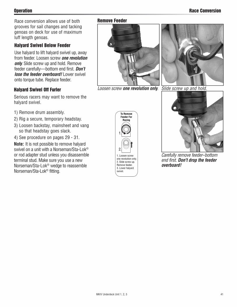
Halyard Swivel Below FeederUse halyard to lift halyard swivel up, away from feeder. Loosen screw one revolution only. Slide screw up and hold. Remove feeder carefully—bottom end first. Don’t lose the feeder overboard! Lower swivel onto torque tube. Replace feeder.
Remove Feeder
Loosen screw one revolution only. Slide screw up and hold.
Carefully remove feeder–bottom end first. Don't drop the feeder overboard!
1.
2.
1. Loosen screw one revolution only.2. Slide screw up.Remove feeder.3. Lower halyard swivel.
To Remove Feeder For
Racing
MKIV Underdeck Unit 1, 2, 3 41

Confirm Gap Between Deck Flange and Tack SwivelCheck to make sure there is a 1/16"–1/8" (2–4 mm) gap between the deck flange and tack swivel. If necessary loosen adjusting nut below and take up on turnbuckle to increase gap between deck flange and tack swivel when turnbuckle is tightened.Storage – Mast DownIn areas where it freezes, do not store system where water can accumulate in foils. When water freezes it will rupture aluminum. Store foils under cover, with grooves facing down or on an angle so water will run out.Storage/TransportingDo not store or transport system with drum assembly extending beyond mast. Remove masthead clevis pin and shift furler up so drum assembly can be strapped securely to mast. Some people remove drum assembly and halyard swivel for storage and transport.After Storage or TransportAfter storing or transporting unit, clean thoroughly including ball bearings. See instructions above.Remove Furler From BoatIn order to prevent foils from locking against upper stay terminal when backstay is released, loosen torque tube screws and lower foil before loosening backstay.
Clean and LubricateKeep unit clean. When you wash boat, flush unit with soap and fresh water. Occasionally lower sail and flush halyard swivel with soap and fresh water.At least twice a year unit should be cleaned more thoroughly by removing line (first note direction of spool) and flushing bearings with soap and fresh water. After unit has dried, apply a dry spray lubricant such as McLube®.Foils may be cleaned by washing with soap and water. A scrap of luff tape may be run up foil to scrub inside grooves. If lubrication is required, spray a thin coat of McLube® SailKote on sail luff tapes away from boat deck.
InspectInspect unit for signs of chafe, wear, or damage. Inspect locking devices below drum and inside torque tube for signs of loosening. Check headstay tension for signs of loosening.Inspect swage fitting and lower toggle for signs of stress corrosion.Inspect Norseman or Sta-Lok® terminal or rod terminal for signs of loosening.Inspect all screws on unit to be sure they have not loosened.Inspect foil to make sure that it has not dropped into torque tube. Periodically inspect wire for signs of wear or unraveling.
Maintenance Clean/Inspect/Remove Furler
42 MKIV Underdeck Unit 1, 2, 3
Check to make sure there is a 1/16"–1/8" (2 - 4mm) gap
WARNING! Periodically inspect items listed below and any others as necessary. Failure to inspect can cause an accident. WARNING! Do not spray foil on boat. McLube®
will cause slippery decks which may result in loss of footing, falling overboard.

Problem Probable Cause SolutionSail will not furl or is difficult to furl.
Jib halyard is wrapping around headstay because angle between mast and and halyard is too shallow
See installation instructions regarding optimal halyard angle. It may be necessary to mount a halyard restrainer on front of your mast to hold halyard to rear.
Jib halyard is wrapping around the headstay because halyard swivel is too low.
See installation instructions regarding optimal halyard swivel height. A wire pendant may be needed at head of sail to raise halyard swivel to proper height.
Jib halyard is too tight. Ease jib halyard.
Foils riding on turnbuckle. Raise foils. See adjusting turnbuckle on page 34.
Foils too high, binding on swage eye. Lower foils until clear. See adjusting turnbuckle on page 34.
Spare halyard is wrapping in sail as it furls. Secure spare halyards away from furling headstay by flipping them behind spreaders
Salt or dirt in bearings. Flush bearings frequently with fresh water and a detergent solution.
Furling line tangled in drum. Overrides are best prevented by using a 7402 ratchet block as the last furling line lead to maintain proper drag on line while unfurling.
Stop knot catching. Make sure knot is a single overhand and is pushed up inside drum.
Sail full of wind. Luff completely before furling or reefing.
Sail flogging too much. Release a short length of sheet, pull some furling line and repeat.
Jib sheets are not free. Free jib sheets.
Foil out of torque tube. Reinstall foil in torque tube and tighten clamp screws.
No wraps of furling line on drum. Remove sheets. Rotate stay wrapping as much furling line on drum as possible.
Lineguard assembly has slipped down. Tighten line guard assembly screws securely.
Line through 7402 ratchet backwards. Rerun line.
Halyard swivel installed upside down. Remount swivel correctly.
Sail will not unfurl or will not unfurl completely.
Jib halyard is wrapping around headstay because angle between mast and halyard is too shallow.
See installation instructions regarding optimal halyard angle. It may be necessary to mount a halyard restrainer on front of your mast to hold halyard to rear.
Jib halyard is wrapping around the headstay because the halyard swivel is too low.
See installation instructions regarding optimal halyard angle.
Foils riding on turnbuckle. Raise foils. See adjusting turnbuckle on page 34.
Foils too high, binding on swage eye. Lower foils. See adjusting turnbuckle on page 34.
Jib halyard is too tight. Ease jib halyard.
Spare halyard is wrapping in sail as it furls. Secure spare halyards away from furling headstay by flipping them behind spreaders
Salt or dirt in bearings. Flush bearings with freshwater and lubricate with dry spray lubricant such as McLube®
Furling line is not free. Free furling line.
Sail will not furl completely.
Insufficient furling line on drum. Remove sheets. Rotate stay, wrapping as much furling line on drum as possible.
Too much line on drum. Adjust amount of line on drum or change position of forward lead block to allow line to roll evenly on drum.
Spare halyard catching in sail as it furls. Move halyards away from furling headsail as above.
Headstay rotates in jerks or elliptically.
Insufficient tension on headstay. Tighten headstay and/or backstay to eliminate sag in headstay.
Sail does not stay furled.
Sail not furled tightly on stay. Maintain drag on sheets while furling.
Furling line not secure. Secure furling line.
Sail will not go up. Luff tape will not go into groove. Check luff tape for fraying.
Check luff tape size.
Sail catching at prefeeder. Flake sail more loosely on deck.
Dirt in groove. Clean groove.
Sail will not raise completely or luff will not tension.
Halyard swivel is hitting end stop. Luff of sail is too long and must be recut.
Angle between halyard and mast is too sharp and halyard is pulling too much to the rear.
Halyard must be routed from a point higher on mast. This may require that any halyard turning blocks aloft be replaced or sail shortened.
Sail will not come down.
Halyard is wrapping on headstay. Angle between headstay and halyard is too shallow and must be optimized per installation instructions.
Halyard swivel off foil. Sail luff too long or foil is too short or low and must be lengthened or raised.
Ultravoilet cover rolls up inside of sail.
Furling line is wrapped on drum in wrong direction. Remove sheets. Pull line to remove all furling line from drum. Turn stay to rewind line on drum in opposite direction. Line guard and cowling alignment may need to be adjusted.
Line jams between guard and plastic spool plate.
Line is not led through windows. Pull line through enclosed window.
Troubleshoot
MKIV Underdeck Unit 1, 2, 3 43
Delrin® is a registered trademark of E. I. du Pont de Nemours and Company or its affiliates. Igus® is a legally registered trademark of Igus® GmbH and/or Igus® Inc. Loctite® is a trademark of Henkel AG & Company KGaA
McLube™ is a registered trademark of McGee Industries, Inc. Sta-Lok® is a registered trademark of Sta-Lok Terminals, Ltd. Torlon® is a registered trademark of Solvay Advanced Polymers
Warranty: www.harken.com/manuals or call, write, email, or fax Harken, Inc.,
Pewaukee, WI USA
Online Product Registration www.harken.com/FurlingWarranty

44 MKIV Underdeck Unit 1
MKIV Underdeck Unit 1 Parts List
H-38817
HFS980
H-38818
HFS980
HFS1052
H-38293
HFG6
84HF
G683
HFG6
85No. Description Order Part No.
Top Cover Assembly w/Screws 1 HFG683Top Cover 2 H-38817Top Cover Screw (M4 x .7 x 10MM) 2 HFS980
Bottom Flange Assembly w/Screws 1 HFG684Flange 2 H-38818Bottom Flange Screw (M4 x .7 x 10MM) 2 HFS980
Guard Assembly 1 HFG685Guard Set 2 H-38293Guard Screw (M6 x 1 x 40MM SHCS) 2 HFS1052
1
21
2
No. Description Order Part No.Rod Adapter Stud (-8) w/Nosepiece 1 7422 -8
1 Stud (Main Body) 1 H-415362 Nosepiece (-8) 1 H-415343 Cotter Pin (3/32" x 1") 2 HFG193
Rod Adapter Stud (-10) w/Nosepiece 1 7423 -101 Stud (Main Body) 1 H-415362 Nosepiece (-10) 1 H-415353 Cotter Pin (3/32" x 1") 2 HFG193
5
*Grip Length
Pin Measurements
*Pin measurementsare "Grip Length."
37424 -12 7424 -17
3
7422 -8 7423 -10
51
24
HFG9
23
3
MP-118
MP-118H-35144AMP-118H-35144A
H-35144AMP-118
MP-129H-35144A
1
2
4
3
5
1
1
2
2
4
H-35144A
3No. Description Order Part No.
Torque Tube Assembly 1 HFG9271 Clamp 1 H-429542 Clamp Screw (M5 x .08 x 12MM SHCS) 4 HFS827
Hub Assembly 1 HFG9231 Cotter Pin (5/32" x 1.250") 4 HFS2032 Clevis Pin (1/2" x 1.146") 4 H-423953 Bearing Cap w/Insert 2 HFG931
A Bearing Cap 1 AL-8101B IGUS® Bushing 1 H-43838
4 Socket Head Cap Screws (M5 x .8 x 10MM) 4 HFS334Ball Plug 5 H-35144ATorlon® Ball Bearing (5/16") 28 MP-129Delrin® Ball Bearing (5/16") 134 MP-118
5 Deck Flange 1 H-42461
4
AB
HFG9
27
1 2
BA
3
MKIV Underdeck Unit 1 45
MKIV Underdeck Unit 1 Parts List
H-42063
H-39625
HFS1105
HFG680
H-42062
HFG295
HFG625
H-39683
HFG343
6
HFG629
7411.30
7411.33
7411.31
7411.32
6
Description Order Part No.Instruction Manual 1 4656Prefeeder 1 947Loctite® Blue 1 833Loctite® Red 2 HFG7395200 Adhesive Set 1 HFG725
5200 Marine Adhesive Sealant 1 HFG722
Injector 1 HFG200 HFG201
Hex Keys5 mm 1 HFG6434 mm 1 HFG6402.5 mm 1 HCP1387
7
Description Order Part No.Lead Block Kit 1 7404
29 mm Outboard Lead Assembly 3 740357 mm Carbo Ratchet Assembly 1 740240 mm Carbo Assembly 1 7401Horn Cleat 1 HCP168
Additional Lead Blocks29 mm Carbo Stand-Up Fixed 1 349Big Bullet Thru-Deck 1 131
Shackle (6 mm) 3 2110Halyard Restrainer 1 945
Sheave/SS Inner Race Only 1 945ASSYClevis Pin (5/16" x 11/4") 1 SP-038Bracket-Large 1 HCP394Cotter Pin (3/32" x 3/4") 1 HFS181
Halyard Deflector 1 7302
8
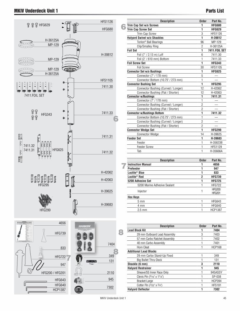
Description Order Part No.Trim Cap Set w/o Screws 1 HFG680Trim Cap Screw Set 1 HFG629
Trim Cap Screw 3 HFS1126Halyard Swivel w/o Shackles 1 H-39812
Torlon® Ball Bearings 96 MP-129Clip/Smalley Ring 2 H-36125A
Foil Set 1 7411.FOIL SETFoil (7' / 2.13 m) Luff 6 7411.30Foil (2' / 610 mm) Bottom 1 7411.33
Foil Screw Set 1 HFG343Foil Screw 30 HFS1105
Connector Set w/o Bushings 1 HFG625Connector (7" / 178 mm) 5 —Connector Bottom (10.75" / 273 mm) 1 —
Connector Bushing Set 1 HFG295Connector Bushing (Curved / Longer) 12 H-42062Connector Bushing (Flat / Shorter) 12 H-42063
Connector w/Bushings 1 7411.31Connector (7" / 178 mm) 1 —Connector Bushing (Curved / Longer) 2 —Connector Bushing (Flat / Shorter) 2 —
Connector w/Bushings Bottom 1 7411.32Connector Bottom (10.75" / 273 mm) 1 —Connector Bushing (Curved / Longer) 2 —Connector Bushing (Flat / Shorter) 2 —
Connector Wedge Set 1 HFG299Connector Wedge 14 H-39625
Feeder Set 1 H-39683Feeder 1 H-35623BFeeder Screw 1 HFS1129Tab 1 H-35666A
HFS1126
H-39812
H-36125A
H-36125AMP-129
MP-129
MP-129
7411.FOIL SET
7411.32 7411.31
HFG299
HFG722
947
HFG200 / HFG201
4656
7
HCP1387HFG640HFG643
Please read these instructions carefully before installing, servicing, or operating the equipment. This manual may be modified without notice. See: www.harken.com/manuals for updated versions.
PLEASE SAVE THESE INSTRUCTIONS
MKIV UNDERDECK JIb REEfINg & fURlINgUnit 1, 2, 3
Installation Manual – Intended for specialized personnel or expert users5003/11-01-2012
Preassembly Parts 4–5 Rigging Parts Check/Tools 6 Dimensions/Sailmaker's Instructions 7 Stay Length Deductions/Stay Into Foil Options 8Hub Assembly Deck Flange 9 Install Hub Assembly in Bow 10–11 Assemble Drum Components 11 Underdeck Lead Block 12Preassembly Top Foil Length (Unit 1) 13 Top Foil Length (Unit 2) 14 Top Foil Length (Unit 3) 15 Short Top Foil (Unit 1) 16 Short Top Foil (Unit 2) 17 Short Top Foil (Unit 3) 18 Foil Length Check 19Assembly Foils/Connectors 20–26 Halyard Swivel 26 Torque Tube Assembly 27 Rod Rigging 28 Attach Turnbuckle/Foils to Boat 29–31 Feeder/Final 32Commissioning Turnbuckle 33–34 Lead Line to Cockpit 35 Halyard Swivel Height/Angle 36 Halyard Restrainer/Tension 37Operation Halyard/Headstay Tension 38 Raise Sails/Storm Sails/Reefing 39–40 Secure Sail 40 Race Conversion 41Maintenance Clean/Lubricate/Inspect 42 Confirm Deck Flange/Tack Swivel Gap 42 Replace Line 42 Storage/Transporting 42 Remove Furler 42Troubleshooting/Warranty
833
HFG739
7404
945
8
2110
349131
7302
46 MKIV Underdeck Unit 2
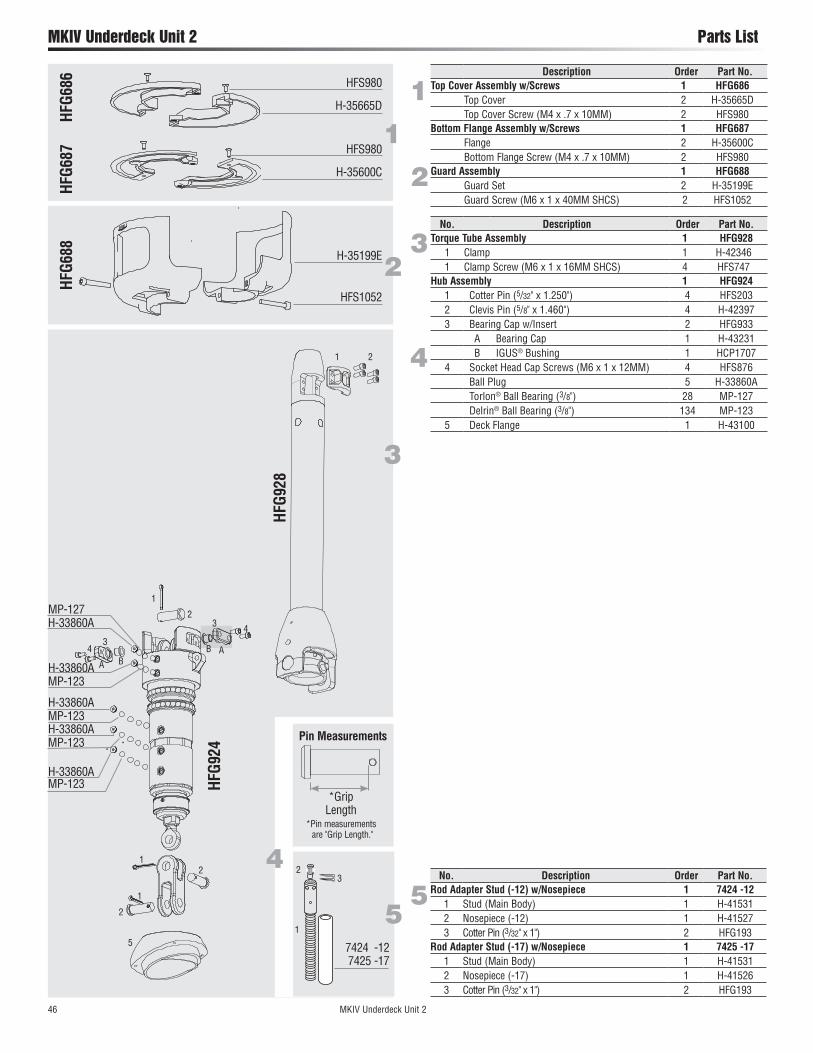
MKIV Underdeck Unit 2 Parts List
*Grip Length
Pin Measurements
*Pin measurementsare "Grip Length."
37424 -12 7424 -17
3
7424 -12 7425 -17
51
2
H-35665D
HFS980
H-35600C
HFS980
HFS1052
H-35199E
HFG6
87HF
G686
HFG6
88
1
2
Description Order Part No.Top Cover Assembly w/Screws 1 HFG686
Top Cover 2 H-35665DTop Cover Screw (M4 x .7 x 10MM) 2 HFS980
Bottom Flange Assembly w/Screws 1 HFG687Flange 2 H-35600CBottom Flange Screw (M4 x .7 x 10MM) 2 HFS980
Guard Assembly 1 HFG688Guard Set 2 H-35199EGuard Screw (M6 x 1 x 40MM SHCS) 2 HFS1052
1
2
No. Description Order Part No.Rod Adapter Stud (-12) w/Nosepiece 1 7424 -12
1 Stud (Main Body) 1 H-415312 Nosepiece (-12) 1 H-415273 Cotter Pin (3/32" x 1") 2 HFG193
Rod Adapter Stud (-17) w/Nosepiece 1 7425 -171 Stud (Main Body) 1 H-415312 Nosepiece (-17) 1 H-415263 Cotter Pin (3/32" x 1") 2 HFG193
54
HFG9
24
3
MP-123
MP-123H-33860AMP-123
MP-127H-33860A
1
2
5
1
1
2
2
4
H-33860A
3No. Description Order Part No.
Torque Tube Assembly 1 HFG9281 Clamp 1 H-423461 Clamp Screw (M6 x 1 x 16MM SHCS) 4 HFS747
Hub Assembly 1 HFG9241 Cotter Pin (5/32" x 1.250") 4 HFS2032 Clevis Pin (5/8" x 1.460") 4 H-423973 Bearing Cap w/Insert 2 HFG933
A Bearing Cap 1 H-43231B IGUS® Bushing 1 HCP1707
4 Socket Head Cap Screws (M6 x 1 x 12MM) 4 HFS876Ball Plug 5 H-33860ATorlon® Ball Bearing (3/8") 28 MP-127Delrin® Ball Bearing (3/8") 134 MP-123
5 Deck Flange 1 H-43100
4
HFG9
28
1 2
H-33860A
MP-123H-33860A
43
BA
3
AB

7404
944
8
2117
2652047
7303
MKIV Underdeck Unit 2 47
MKIV Underdeck Unit 2 Parts List
H-42033
H-39487
HFS1106
HFS1127
H-42032
HFG296
HFG626
H-39559
HFG348
HFG672
6
6Description Order Part No.
Trim Cap Set w/o Screws 1 HFG681Trim Cap Screw Set 1 HFG672
Trim Cap Screw 3 HFS1127Halyard Swivel w/o Shackles 1 H-39794
Torlon® Ball Bearings 92 MP-127Clip/Smalley Ring 2 H-38028A
Foil Set 1 7412.FOIL SETFoil (7' / 2.13 m) Luff 8 7412.30Foil (2' / 610 mm) Bottom 1 7412.33
Foil Screw Set 1 HFG348Foil Screw 38 HFS1106
Connector Set w/o Bushings 1 HFG626Connector (9" / 229 mm) 7 —Connector Bottom (13" / 330 mm) 1 —
Connector Bushing Set 1 HFG296Connector Bushing (Curved / Longer) 16 H-42032Connector Bushing (Flat / Shorter) 16 H-42033
Connector w/Bushings 1 7412.31Connector (9" / 229 mm) 1 —Connector Bushing (Curved / Longer) 2 —Connector Bushing (Flat / Shorter) 2 —
Connector w/Bushings Bottom 1 7412.32Connector Bottom (13" / 330 mm) 1 —Connector Bushing (Curved / Longer) 2 —Connector Bushing (Flat / Shorter) 2 —
Connector Wedge Set 1 HFG300Connector Wedge 18 H-39487
Feeder Set 1 H-39559Feeder 1 H-33931BFeeder Screw 1 HFS1129Tab 1 H-35671A
7412.30
7412.33
7412.31
7412.32
H-38028A
H-38028AMP-127
MP-127
MP-127
7412.FOIL SET
H-39794
7412.31 7412.32
HFG300
HFG681
Description Order Part No.Instruction Manual 1 4656Prefeeder 1 947Loctite® Blue 1 833Loctite® Red 2 HFG7395200 Adhesive Set 1 HFG725
5200 Marine Adhesive Sealant 1 HFG722
Injector 1 HFG200 HFG201
Hex Keys6 mm 1 HFG6445 mm 1 HFG6434 mm 1 HFG6403 mm 1 HCP1089
7
7
Description Order Part No.Lead Block Kit 1 7404
29 mm Outboard Lead Assembly 3 740357 mm Carbo Ratchet Assembly 1 740240 mm Carbo Assembly 1 7401Horn Cleat 1 HCP168
Additional Lead Blocks40 mm Carbo Stand-Up Fixed 1 26522.25" Thru-Deck 1 047
Shackle (8 mm) 3 2117Halyard Restrainer 1 944
Sheave/SS Inner Race Only 1 944ASSYClevis Pin (1/4" x .9") 1 HFG467Bracket-Small 1 HCP393Cotter Pin (1/16" x 1/2") 1 HFS118
Halyard Deflector 1 7303
8
HFG722
947
HFG200/HFG201
4656
Please read these instructions carefully before installing, servicing, or operating the equipment. This manual may be modified without notice. See: www.harken.com/manuals for updated versions.
PLEASE SAVE THESE INSTRUCTIONS
MKIV UNDERDECK JIb REEfINg & fURlINgUnit 1, 2, 3
Installation Manual – Intended for specialized personnel or expert users5003/11-01-2012
Preassembly Parts 4–5 Rigging Parts Check/Tools 6 Dimensions/Sailmaker's Instructions 7 Stay Length Deductions/Stay Into Foil Options 8Hub Assembly Deck Flange 9 Install Hub Assembly in Bow 10–11 Assemble Drum Components 11 Underdeck Lead Block 12Preassembly Top Foil Length (Unit 1) 13 Top Foil Length (Unit 2) 14 Top Foil Length (Unit 3) 15 Short Top Foil (Unit 1) 16 Short Top Foil (Unit 2) 17 Short Top Foil (Unit 3) 18 Foil Length Check 19Assembly Foils/Connectors 20–26 Halyard Swivel 26 Torque Tube Assembly 27 Rod Rigging 28 Attach Turnbuckle/Foils to Boat 29–31 Feeder/Final 32Commissioning Turnbuckle 33–34 Lead Line to Cockpit 35 Halyard Swivel Height/Angle 36 Halyard Restrainer/Tension 37Operation Halyard/Headstay Tension 38 Raise Sails/Storm Sails/Reefing 39–40 Secure Sail 40 Race Conversion 41Maintenance Clean/Lubricate/Inspect 42 Confirm Deck Flange/Tack Swivel Gap 42 Replace Line 42 Storage/Transporting 42 Remove Furler 42Troubleshooting/Warranty
HFG739
HFG640HFG643HFG644
HCP1089
HFG833

48 MKIV Underdeck Unit 3
MKIV Underdeck Unit 3 Parts List
*Grip Length
Pin Measurements
*Pin measurementsare "Grip Length."
37424 -12 7424 -17
3
7426 -22 7427 -30
51
2
MP-116
MP-116H-38168MP-116H-38168
H-38168MP-116
MP-128H-38168
1
2
4
3
5
1
1
2
No. Description Order Part No.Rod Adapter Stud (-22) w/Nosepiece 1 7426 -22
1 Stud (Main Body) 1 H-418122 Nosepiece (-22) 1 H-418113 Cotter Pin (3/32" x 13/4") 2 HFG3194 Stud Cap (7/8") ID (not shown) 1 HFG303
Rod Adapter Stud (-30) w/Nosepiece 1 7427 -301 Stud (Main Body) (not shown) 1 H-418142 Nosepiece (-30) 1 H-418133 Cotter Pin (3/32" x 13/4") 2 HFG3194 Stud Cap (7/8") ID (not shown) 1 HFG303
5
H-35025D
HFS1060
H-35465C
HFS1060
HFS873
H-33758E
HFG6
90HF
G689
HFG6
91
1
2
Description Order Part No.Top Cover Assembly w/Screws 1 HFG689
Top Cover 2 H-35025DTop Cover Screw (M5 x .8 x 12MM) 2 HFS1060
Bottom Flange Assembly w/Screws 1 HFG690Flange 2 H-35465CBottom Flange Screw (M5 x .8 x 12MM) 2 HFS1060
Guard Assembly 1 HFG691Guard Set 2 H-33758EGuard Screw (M8 x 1.25 x 50MM SHCS) 2 HFS873
1
2
2
4
H-38168
3
4
3No. Description Order Part No.
Torque Tube Assembly 1 HFG9291 Clamp 1 H-429672 Clamp Screw (M8 x 1.25 x 25MM SHCS) 4 HFS1107
Hub Assembly (3/4") 1 HFG9251 Cotter Pin (5/32" x 1.250") 4 HFS2032 Clevis Pin (3/4" x 1.766") 4 H-424033 Bearing Cap w/Insert 2 HFG935
A Bearing Cap 1 H-44674B IGUS® Bushing 1 HCP1684
4 Socket Head Cap Screws (M6 x 1 x 12MM) 4 HFS876Ball Plug 5 H-38168Torlon® Ball Bearing (1/2") 27 MP-128Delrin® Ball Bearing (1/2") 128 MP-116
5 Deck Flange 1 H-44680Hub Assembly (7/8") 1 HFG926
1 Cotter Pin (5/32" x 1.250") 4 HFS2032 Clevis Pin (7/8" x 1.958") 4 H-424043 Bearing Cap w/Insert 2 HFG935
A Bearing Cap 1 H-44674B IGUS® Bushing 1 HCP1684
4 Socket Head Cap Screws (M6 x 1 x 12MM) 4 HFS876Ball Plug 5 H-38168Torlon® Ball Bearing (1/2") 27 MP-128Delrin® Ball Bearing (1/2") 128 MP-116
5 Deck Flange 1 H-44680
4
4
HFG9
25 (3
/4")
HF
G926
(7/8
")
AB
HFG9
29
1 2
BA
3

MKIV Underdeck Unit 3 49
MKIV Underdeck Unit 3 Parts List
HFG349
HFG672
6
H-39751
7413.30
H-42073
7413.31
H-39756
7413.32
7413.10 FOILSET
7413.33
6Description Order Part No. (3/4, 7/8)
Trim CapTop (with Holes) 1 H-39751Bottom (with Pegs) 1 H-39752
Trim Cap Screw Set 1 HFG672Trim Cap Screw 3 HFS1127
Halyard Swivel w/o Shackles 1 H-39392Torlon® Ball Bearings 88 MP-128Clip/Smalley Ring 2 H-39916
Foil Set 1 7413.10 FOILSETFoil (7' / 2.13 m) Luff 10 7413.30
Foil (2'/610 mm) Bottom 1 7413.33Foil Screw Set 1 HFG349
Foil Screw 46 HFS1106Connector Set 1 HFG627
Connector (93/4" / 248 mm) 9 7413.31Bottom Connector (14" / 356 mm) 1 7413.32
Connector Bushing Set 1 HFG297Connector Bushing Top (Curved / Longer) 20 H-42073Connector Bushing Bottom (Flat / Shorter) 20 H-42074
Connector Wedge Set 1 HFG324Connector Wedge 22 H-39487
Feeder with Screw and Tab 1 H-39756Feeder 1 H-38332BFeeder Screw 1 HFS1130Tab 1 H-38372A
H-42074
HFG297
HFG627
HFG324
H-39392
H-39916
H-39916MP-128
MP-128
MP-128
Description Order Part No. (3/4, 7/8)
Instruction Manual 1 4656Prefeeder 1 947Loctite® Blue 1 833Loctite® Red 2 HFG7395200 Adhesive Set 1 HFG725
5200 Marine Adhesive Sealant 1 HFG722
Injector 1 HFG200 HFG201
Hex Keys10 mm 1 HFG6476 mm 1 HFG6444 mm 1 HFG6403 mm 1 HCP1089
7
Description Order Part No.Lead Block Kit 1 7404
29 mm Outboard Lead Assembly 3 740357 mm Carbo Ratchet Assembly 1 740240 mm Carbo Assembly 1 7401Horn Cleat 1 HCP168
Additional Lead Blocks57 mm Carbo Single Swivel 1 2600Stainless Steel Eyestrap 1 137Stand-Up Spring 1 071Thru-Deck (2.25") (not shown) 1 HC7981
Shackle (10 mm) 3 2124Halyard Restrainer 1 945
Sheave/SS Inner Race Only 1 945ASSYClevis Pin (5/16" x 11/4") 1 SP-038Bracket-Large 1 HCP394Cotter Pin (3/32" x 3/4") 1 HFS181
Halyard Deflector 1 7304
8
HFG640HFG644HFG647
HCP1089
HFG722
947
HFG200/HFG201
4656
MKIV UNDER-DECK Jib Reefing & Furling
Installation Manual
Unit 1, 2, 3
WARNING!: Strictly follow all instructions to avoid an accident, damage to your vessel, personal injury or death. See www.harken.com for additional safety information.
833
HFG739
HFS1127H-39752
7404
945
8
2124
7304
7 2600137
071

This Page Intentionally Left Blank
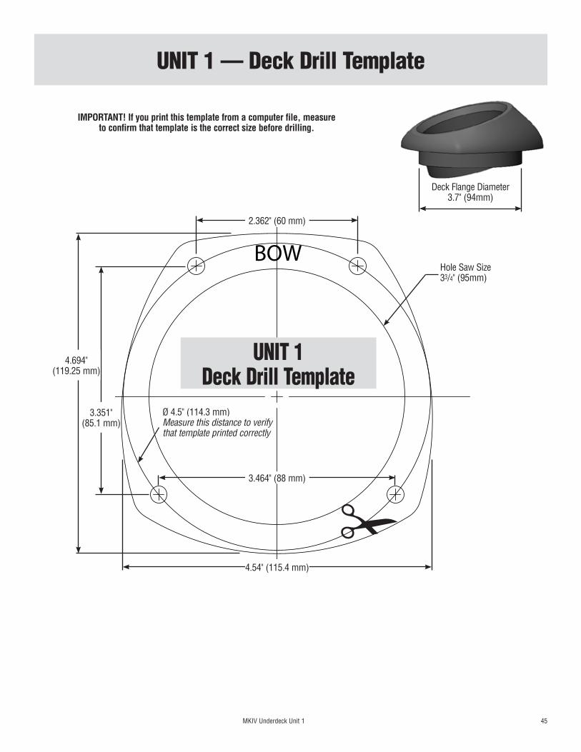
MKIV Underdeck Unit 1 45
UNIT 1 — Deck Drill Template
BOW
UNIT 1 Deck Drill Template
!
Hole Saw Size 33/4" (95mm)
2.362" (60 mm)
3.464" (88 mm)
3.351" (85.1 mm)
4.54" (115.4 mm)
4.694" (119.25 mm)
Ø 4.5" (114.3 mm)Measure this distance to verify that template printed correctly
Deck Flange Diameter 3.7" (94mm)
IMPORTANT! If you print this template from a computer file, measure to confirm that template is the correct size before drilling.

This Page Intentionally Left Blank

46 MKIV Underdeck Unit 2
UNIT 2 — Deck Drill Template
BOW
UNIT 2 Deck Drill Template
!
Hole Saw Size 41/4" (110 mm)
2.678" (68 mm)
3.936" (100 mm)
3.698" (93.9 mm)
5.07" (128.8 mm)
5.28" (134.1 mm)
Ø 5.032" (127.82 mm)Measure this distance to verify that template printed correctly
Deck Flange Diameter 4.2" (106.5 mm)
IMPORTANT! If you print this template from a computer file, measure to confirm that template is the correct size before drilling.

This Page Intentionally Left Blank

MKIV Underdeck Unit 3 47
UNIT 3 (3/4, 7/8) — Deck Drill Template
BOW
UNIT 3 (3/4, 7/8) Deck Drill Template
!
Hole Saw Size 51/2" (140mm)
3.444" (87.5 mm)
5.2" (132.1 mm)
4.665" (118.5 mm)
6.531" (165.9 mm)
6.77" (172 mm)
Ø 6.471" (164.36 mm)Measure this distance to verify that template printed correctly
Deck Flange Diameter 5.45" (138.5 mm)
IMPORTANT! If you print this template from a computer file, measure to confirm that template is the correct size before drilling.

Corporate HeadquartersN15W24983 Bluemound Rd, Pewaukee, WI 53072 USA
Telephone: (262) 691-3320 • Fax: (262) 701-5780Web: www.harken.com • Online Catalog: www.harkenstore.com
Email: [email protected]
Harken Australia Pty, Ltd.1B Green Street, Brookvale, N.S.W. 2100, Australia
Telephone: (61) 2-8978-8666 • Fax: (61) 2-8978-8667Web: harken.com.au • Email: [email protected]
Harken FranceZA Port des Minimes, BP 3064, 17032 La Rochelle Cedex 1, France
Telephone: (33) 05.46.44.51.20 • Fax: (33) 05.46.44.25.70Web: harken.fr • Email: [email protected]
Harken Italy S.p.A.Via Marco Biagi, 14, 22070 Limido Comasco (CO) Italy Telephone: (39) 031.3523511 • Fax: (39) 031.3520031
Web: harken.it • Email: [email protected]
Harken New Zealand, Ltd.30-36 Fanshawe Street, P.O. Box 1951, Auckland 1001, New Zealand
Telephone: (64) 9-303-3744 • Fax: (64) 9-307-7987Web: harken.co.nz • Email: [email protected]
Harken Polska SP ZOOul. Rydygiera 8, budynek 3A, lokal 101, I piętro, 01-793 Warszawa, Poland
Tel: +48 22 561 93 93 • Fax: +48 22 839 22 75Web: harken.pl • Email: [email protected]
Harken Sweden ABMain Office and Harken Brandstore: Västmannagatan 81B
SE-113 26 Stockholm SwedenTelephone: (46) 0303 61875 • Fax: (46) 0303 61876
Mailing address: Harken Sweden AB, Box 64, SE -440 30 MarstrandWeb: harken.se • Email: [email protected]
Harken UK, Ltd.Bearing House, Ampress Lane, Lymington, Hampshire S041 8LW, England
Telephone: (44) 01590-689122 • Fax: (44) 01590-610274Web: harken.co.uk • Email: [email protected]
Please visit: http://www.harken.com/locator.aspx to locate Harken dealers and distributors
Printed in USA 4656 01/14