model dev1200 exterior mounted ventilator
TRANSCRIPT

READ AND SAVE THESE INSTRUCTIONS
MODEL DEV1200EXTERIOR MOUNTED VENTILATORFOR USE WITH WCWH, VICH, DBCV, DICV, DCWH, DCWL, DCWN, DTWS AND DCIH WJLJOH RANGE, MMD HOODS. 30" TO 66" WIDE, 9" TO 18" HIGH.
WARNINGTO REDUCE THE RISK OF FIRE, ELECTRIC SHOCK, OR INJURY TO PERSONS, OBSERVE THE FOLLOWING:1. Usethisunitonlyinthemannerintendedbythemanu-
facturer.Ifyouhavequestions,contactthemanufactureroryourdistributor.
2. Beforeservicingorcleaningunit,switchpoweroffatservicepanelandlocktheservicedisconnectingmeanstopreventpowerfrombeingswitchedonaccidentally.When the service disconnecting means cannot belocked,securely fastenaprominentwarningdevice,suchasatag,totheservicepanel.
3. Installationworkandelectricalwiringmustbedonebyaqualifiedperson(s)inaccordancewithallapplicablecodesandstandards,includingfire-ratedconstructioncodesandstandards.
4. Sufficient air is needed for proper combustion andexhaustingofgasesthroughtheflue(chimney)offuelburningequipmenttopreventbackdrafting.Followtheheatingequipmentmanufacturer'sguidelineandsafetystandards such as those published by the NationalFireProtectionAssociation(NFPA),andtheAmericanSocietyforHeating,RefrigerationandAirConditioningEngineers(ASHRAE),andthelocalcodeauthorities.
CAUTION1. Forgeneralventilatinguseonly.Donotusetoexhausthaz-
ardousorexplosivematerialandvapors.2. Toavoidmotorbearingdamageandnoisyand/orunbalanced
impellers,keepdrywallspray,constructiondust,etc.offpowerunit.
3. Pleasereadspecificationlabelonproductforfurtherinforma-tionandrequirements.
4. Electricalcircuit,includingspeedcontrol,(ifused),mustberated6AmPSminimum.
PLAN THE INSTALLATION
1. Locate the ventilator sothelengthoftheductrunand number of elbowsneeded are kept to aminimum.
2. Where possible, ventila-tor should be centeredbetweenwallstudsorroofrafters.
3. Avoid pipes, wires, orotherductwork thatmaybe running through thewall.
ALL INSTALLATIONS
MODEL VOLTS AMPS CFM DUCT SIZE
DEV1200 120 3.0 1200 10"DIA.
SPECIFICATIONS
INSTALLER: Leave This Manual With The HomeownerHOMEOWNER: Use And Care Information On Page 4
TYPICAL ROOF MOUNTED INSTALLATION TYPICAL WALL MOUNTED INSTALLATION
5. Whencuttingordrillingintowall,orceiling,donotdam-ageelectricalwiringorotherhiddenutilities.
6. Ductedfansmustalwaysbeventedtotheoutdoors.7. Toreduceriskoffire,useonlymetalductwork.8. Thisunitmustbegrounded.
WARNING
MODEL DEV1200EXTERIOR VENTILATOR
10" ROUNDDUCT
SOFFIT
WALL HOOD CANOPY
(island canopy available)
MODELDEV1200
EXTERIORVENTILATOR
10" ROUND DUCT
SOFFIT
10" ROUND ELBOW
WALL HOOD CANOPY
(island canopy available)
Blower Dimensions22x30.828x12.724

1. Chooseapositionontheoutsidewall.makesurethatnowallstuds,pipesorwiresrunthroughtheopeningarea.
2. From inside, mark and drill a guide hole centeredbetweenwall studs.
PREPARE THE INSTALLATION LOCATION
ROOF INSTALLATIONS WALL INSTALLATIONS
1. Locatetheventilatorontherearslopeoftheroof.Placeitinalocationtominimizeductrun.Thelocationshouldbefreeofobstacles(T.V.leads,electricallines,etc.).Iftheventilatortopislevelwiththeroofpeak,itwillnotbeseenfromthestreet.Keepthisapproximatelocationinmindasyouworkfromwithintheattic.
2. markanddrill aguide hole centeredbetween roofrafters.
2
3. Fromtheoutside,usetheguideholeasastartingpointtolayouttheinstallation:A. UseaT-squaretomeasure913/16"totheleftofthe
guide hole, then up 1211/16" to locate the top-leftcornerofthelayout.
B. Startingfromthetop-leftcorner,marktherectan-gularcutout(18"Wx20½"H)andremoveonlytheshinglesinthisarea.
C. markan11" diameter holecenteredontheguidehole.Cutthisholethroughtheroofboard(s).
D. markandcuta1¼" diameter holethroughtheroofboard(s)whereshown.
4. Forflatroofinstallations,buildacurbthatwillmounttheventilatorataminimumpitchof2/12.Dischargeendoftheventilatorshouldbepointedawayfromprevailingwinds.
PREPARE THE INSTALLATION LOCATION
3. Fromtheoutside,usetheguideholeasastartingpointtolayouttheinstallation:A. UseaT-squaretomeasure1113/16"totheleftofthe
guide hole, then up 1411/16" to locate the top-leftcornerofthelayout.
B. Startingfromthetop-leftcorner,marktherectangularcutout(22"Wx29½"H)andremoveonlythesidinginthisarea.
C. markan11" diameter holecenteredontheguidehole.Cutthisholethroughtheroofboard(s).
D. markandcuta1¼" diameter holethroughtheroofboard(s)whereshown.
6¾" 2"
29½"22"
2"

1. Removethecoverandscrews.
2. AttachanappropriateU.L.approvedcableconnectorintheholeattherearofthewiringbox.
3. RemoveroofingnailsfromshinglesaroundtheTOPandSIDESofthecutoutareaonly.Carefullylifttheshinglestoallowthebackflashingsheetontheventilatorhousingtofitunderthem.
4. Centertheventilatorringinthe11"diameterhole,makingsurethatthe1¼"diameterelectricalwiringholealignswiththeholeinthewiringbox.
5. Attachtheventilatortotheroofwithsix(6)screwspro-vided.Itisrecommendedthatthescrewsbelocatedinsidetheventilatorhousing.Drillpilotholesifnecessary.
6. Usingagoodgradeofroofingcement,sealallof theshinglesaroundthehousingandflashingsheetaswellasthemountingscrewheads.
7. Bringelectricalwiringthroughtheholeinthewiringboxandsecureitaccordingtolocalcodes.
8. maketheelectricalconnectionswiththeproperconnectorforthetypeofwiringbeingused.Connectblacktoblack,whitetoblue,andthegreenorbarewiretogroundingscrew.
9. Replacecoverandscrews.Donotpinchwiringunderthecover.
10.makesuredamperopensandclosesfreely.
1. Placea largebeadofcaulkon thebacksideof thehousingallalongtheouteredges.
2. Centertheventilatorringinthe11"diameterhole,makingsurethatthe1¼"diameterelectricalwiringholealignswiththeholeinthewiringbox.
3. Attachventilatortothewallwiththesix(6)screwspro-vided.Itisrecommendedthatthescrewsbelocatedinsidetheventilatorhousing.Drillpilotholesifneces-sary.
4. Usingagoodgradeofcaulk,sealallaroundthemount-ingscrewheads.
5. Bringelectricalwiringthroughtheholeinthewiringboxandsecureitaccordingtolocalcodes.
INSTALL THE VENTILATOR
ROOF INSTALLATIONS
INSTALL THE VENTILATOR
WALL INSTALLATIONS
3
6. maketheelectricalconnectionswiththepropercon-nectorforthetypeofwirebeingused.Connectblacktoblack,whitetoblue,andgreenorbarewiretogroundingscrew.
7. Replacecoverandscrews.Donotpinchwiringundercover.
8. makesuredamperopensandclosesfreely.
9. Topandsideflangesofthebackplatemaybecoveredwithtrimstrips.Donotblockgrilleopening atbottomwith trim. It will adversely affect performance of theventilator.
BLACKTO
BLACK
120 VACLINE
IN
WHITETO
BLUE
GROUNDTO
GROUNDINGSCREW
BLACKTO
BLACK
120 VACLINE
IN
WHITETO
BLUE
GROUNDTO
GROUNDINGSCREW

GREEN
WHITEBLACK
BLACK
WHITE
GR
EE
N
BLACK
WHITE
GREEN
ROUGH-IN PLATE LEAD
ROUGH-IN PLATE LEAD
WIRING BOX
EXTERIORVENTILATOR
BLACKBLACKBR
OW
N
CAPACITOR
WHITE
BLUE
BLACK
GREEN / YELLOW
M GROUND LINE IN120 VAC
60 HZ10 A MAX.
99043051EF20221
1. Run10"roundsteelductwork,fromexteriorventilatortotheinstallationlocation.Forbestperformance,usethestraightestpossibleductrunandthefewestnumberofelbows.Tapealljoints.
2. Run120VACelectricalpowercablefromservicepanelandfromremoteventilatortoinstallationlocation.
3. Removewiringboxcover.Removeknockoutsfromthewiringbox.Feed6" of power cable throughopeningsandattachcablestowiringboxwithappropriateconnec-tors.
VIKING RANGE, MMDgREENWOOD,mISSISSIPPI38930USA
4. Wireblacktoblack,whitetowhite,andgreenorbarewirebeneathgreengroundscrew.Replacewiringboxcover.
5. Connectductworktotransitionandtapejoint.
6. Turnonpowerandcheckventilatoroperation.
INSTALL THE ROUGH-IN PLATE USE AND CARE
Disconnectelectricalpowersupplyandlockoutservicepanelbeforecleaningorservicingthisunit.
CLEANING
Removecoverandcarefullyvacuumventilatorandinsideofhousing.Becarefulnottobendorotherwisedamageventilatorwheel.
MOTOR LUBRICATION
Themotorispermanentlylubricated.Donotoilordisas-semblemotor.

VEUILLEZ LIRE CES DIRECTIVES ET LES CONSERVER
MODÈLE DEV1200VENTILATEUR MONTÉ À L’EXTÉRIEUR
AVERTISSEMENTOBSERVEZ LES DIRECTIVES CI-DESSOUS DE MANIÈRE À RÉDUIRE LES RISQUES D’INCENDIE, DE CHOC ÉLEC-TRIQUE OU DE BLESSURES CORPORELLES.1. N’utilisezcetappareilquedelamanièreprévueparlefa-
bricant.Sivousavezdesquestions,contactezlefabricantouledistributeur.
2. Avantdeprocéderàlaréparationouàl’entretiendel’appa-reil,coupezl’alimentationdupanneaud’entréed’électricitéetverrouillezledispositifdesectionnementdemanièreàempêcherquelecourantnesoitaccidentellementrétabli.S’ilestimpossibledeverrouillerledispositifdesection-nement,fixezsolidementunsystèmedeprotectionbienenvue,parexempleuneétiquette,aupanneaud’entréed’électricité.
3. Laposedel’appareiletlestravauxd’électricitédoiventêtreeffectuéspardespersonnesqualifiéesenrespectantla réglementation en vigueur, notamment les codes etnormesdelaconstructionayanttraitàlarésistanceaufeu.
4. Pouréviterlesrefoulements,l’apportd’airdoitêtresuffi-santdemanièreàbrûleretàévacuer,parleconduitdefumée(cheminée), lesgazproduitspar lesappareilsàcombustibles.Respectez lesdirectivesdu fabricantdel’appareil de chauffage et les normes de sécurité, no-tammentcellespubliéespar laNationalFireProtectionAssociation(NFPA),laAmericanSocietyforHeating,lesRefrigerationandAirConditioningEngineers(ASHRAE)etlescodesdesautoritéslocales.5
5. Veillezànepasendommager lecâblageélectriqueoud’autreséquipementsnonapparentslorsdeladécoupeouduperçagedumurouduplafond.
ATTENTION1. Cetappareilnedoitservirqu’àlaventilationgénérale.Ne
l’utilisezpaspouréliminerdesmatièresnidesvapeursdangereusesouexplosives.
2. Pouréviterd’endommagerlesroulementsdemoteur,dedéséquilibrerlespalesoudelesrendrebruyantes,débar-rassezl’appareildelapoussièredeplâtre,deconstruction,etc.
3. Veuillezlirel’étiquettedespécificationsduproduitpourobtenirplusderenseignements,notammentsurlesnor-mes.
4. Lecircuitélectrique,ycomprislacommandederégime(lecaséchéant),doitavoirauminimumunepuissancenominalede6ampères.
PLANIFICATION DE LA POSE
1. L’emplacementdeposeduventilateurdoitêtrechoiside manière à réduire lepluspossiblel’utilisationdeconduitsetdecoudes.
2. Sicelaestenvisageable,leventilateurdoitêtrecentréentre lespoteauxmurauxetleschevronsdutoit.
3. Évitezlestuyaux,lesfilsouautresconduitsquipeuventpasserdanslesmurs.
TOUS LES TYPES DE POSE
SPÉCIFICATIONS
INSTALLATEUR : Veuillez laisser ce manuel au propriétaire PROPRIÉTAIRE : La page 4 contient des renseignements portant sur l’utilisation et l’entretien
POSE TYPE - VENTILATEUR MONTÉ SUR LE TOITPOSE TYPE - VENTILATEUR MONTÉ SUR LE MUR
MODEL DEV1200EXTERIOR VENTILATOR
10" ROUNDDUCT
SOFFIT
WALL HOOD CANOPY
(island canopy available)
MODELDEV1200
EXTERIORVENTILATOR
10" ROUND DUCT
SOFFIT
10" ROUND ELBOW
WALL HOOD CANOPY
(island canopy available)
6. Lesventilateurscanalisésdoiventtoujoursêtreventilésàl’airlibre.
7. Pourréduirelesrisquesd’incendie,utilisezseulementdesconduitsenmétal.
8. Cetappareildoitêtremisàlaterre.
AVERTISSEMENT
CUBESÀLAMINUTE(PIEDS
CUBESÀLA DIMENSIONMODÈLE VOLTS AMPÈRESMÈTRES MINUTE DUCONDUIT
DEV1200 120 3.0 1200 DIAMÈTREDE25,4cm
(10po)
POURUTILISATIONAVECLESHOTTESDECUISINEWJLJOH SBOHF, MMD VCWH,VICH,DBCV,DICV,DCWH,DCWL,DCWN,DTWS,ETDCIH,DE30"À66"(76,2CMÀ167,6CM)DELARGEUR,9"À18"(22,9CMÀ45,7CM)DEHAUTEUR.
VVENTILATEUREXTÉRIEURmODÈLEDEV1200
VCONDUITDIAmÈTREDE
25,4Cm(10PO)
VSOFFITTE
VCONDUITDIAmÈTRE
DE25,4Cm(10PO)
VVENTILATEUREXTÉRIEUR
MODÈLEDEV1200
VSOFFITTEVVERRIÈRE
HOTTEDEmUR(verrièredeîle
disponible)
VVERRIÈREHOTTEDEmUR
(verrièredeîledisponible)
VCOUDEDIAmÈTREDE25,4Cm(10PO)
Dimensions de ventilateur55,9cm(22")x78,3cm(30.828")x32,3cm(12.724")

6¾" 2"
29½"22"
2"
1. Choisissezunemplacementsurlemurextérieur.Assurez-vousqu’aucunpoteaumural, tuyauoucâblenepasseauniveaudel’ouverture.
2. Del’intérieur,tracezunpointderepèreetpercezunavant-trou centréentrelespoteaux muraux.
PRÉPARATION DE L’EMPLACEMENT DE POSE
POSES SUR LES TOITS POSES SUR LES MURS1. Choisissezunemplacementdeposepourleventilateursurla
pentearrièredutoit.Placez-ledansunemplacementréduisantaumaximuml’utilisationdeconduits.Cetemplacementdoitêtreexemptd’obstacles(filsdetéléviseur,lignesélectriques,etc.)Siledessusduventilateuraffleurelefaîtedutoit,ilnepourraêtreaperçudelarue.gardezcetemplacemententêtependantquevoustravaillezàpartirdugrenier.
2. Tracezunpointderepèreetpercezunavant-trou centréentreleschevrons du toit.
6
3. De l’extérieur, utilisez l’avant-trou comme point de départpourprocéderautraçagedelapose.A. UtilisezuneéquerreenTetmesurezunpointà24,9cm
(913/16po)à lagauchedel’avant-trou,puisunautrepointverslehautà30,7cm(1211/16po)pourdéterminerlecoingauchesupérieurdutracé.
B. Encommençantparlecoinsupérieurgauche,marquezunedécouperectangulairede45,7cmdelarg.sur52,1cmdehaut.(18podelarg.sur20½podehaut.)puisenlevezseulementlesbardeauxdecettezone.
C. marquezuntroude27,9 cm de diamètre(11 po)ayantpourcentrel’avant-trou.Coupezcetroudepartenpartdespanneauxdutoit.
D. marquezuntroud’un diamètre de 3,2 cm (1 ¼ po) etdécoupezdepartenpartdespanneauxdetoitcommeindiqué.
4. Pourlesposessurlestoitsplats,construisezuncadrepor-teurquisupporteraleventilateuravecunepenteminimalede2/12.L’extrémitéduconduitd’évacuationduventilateurnedoitpaspointerdansladirectiondominanteduvent.
PRÉPARATION DE L’EMPLACEMENT DE POSE
3. De l’extérieur, utilisez l’avant-trou comme point de départpourprocéderautraçagedelapose.A. UtilisezuneéquerreenTetmesurezunpointà30cm
(1113/16po)àlagauchedel’avant-trou,puisunautrepointverslehautà37,3cm(1411/16po)pourdéterminerlecoinsupérieurgauchedutracé.
B. Encommençantparlecoinsupérieurgauche,marquezunedécouperectangulairede55,9cmdelarg.sur74,9cmdehaut.(22podelarg.sur29½podehaut.)etenlevezseulementleslambrisextérieursdecettezone.
C. marquezuntroude27,9 cm de diamètre(11 po)ayantpourcentrel’avant-trou.Coupezcetroudepartenpartdespanneauxdutoit.
D. marquezuntroud’un diamètre de 3,2 cm (1 ¼ po) etdécoupezdepartenpartdespanneauxdetoitcommeindiqué.
55,9 cm (25 po)
11" dia.hole
1"
Ø
20½"
Ø15"
913/16"
1¼" dia. hole
Ro
of
Raf
ter
REMOVE SHINGLES
Ro
of
Raf
ter
Guide hole(centered
between rafters)
1211 /16"
18"
38,1cm(15po)
32,2cm(12-11/16po)
52,1cm(20-1/2po)
2,5cm(1po)
45,7cm(18po)
24,9cm(9-13/16po)
Diamètrede27,9cm(11po)
Troud'undiamètrede3,2cm(1¼po)
ENLEVEZLESBARDEAUX
Pout
relle
de
toit
Pout
relle
de
toit
Troudeguide(centréentre
poutrelles)
22"
29½"
1411 /16"
1113/16"
Wal
l Stu
d
Wal
l Stu
d
11" dia.hole
17"
1¼" dia. hole
3"
Ø
Ø
REMOVESIDING
Guide hole(centered between studs)
Troudeguide(centréentrepoutrelles)
Troud'undiamètrede3,2cm(1¼po)
ENLEVEZVOIEDEGARAGE
Pout
relle
de
toit
Pout
relle
de
toit
Diamètrede
27,9cm(11po)
43,2cm(17po)
37,3cm(14-11/16po) 7,6cm
(3po)
74,9cm(29-1/2po)
55,9cm(22po)
30cm(11-13/16po)
5 cm (2 po)
74,9 cm (29 ½ po)
17,1 cm (6¾ po)
5 cm (2 po)

1. Retirezlecouvercleetlesvis.
2. FixezunconnecteurdecâblehomologuéU.L.dansl’ouvertureàl’arrièreduboîtierdecâblage.
3. Retirezseulement lesclousàtoituredesbardeauxquisetrouventsurleDESSUSetsurlesCÔTÉSdelasurfacededécoupe.Soulevezdélicatementlesbardeauxdemanièreà permettre à la feuille de tôle noire arrière du boîtier deventilateurdeseglissersouslesbardeaux.
4. Centrez l’anneau de ventilateur dans le trou de 27,9cm(11po) de diamètre, et assurez-vous que l’orifice pour lecâblageélectriquede3,2cm(1¼po)dediamètrecoïncideavecl’orificeduboîtierdecâblage.
5. Fixezleventilateurautoitàl’aidedessix(6)visfournies.Ilestrecommandédeplacerlesvisàl’intérieurduboîtierduventilateur.Percezdesavant-trousaubesoin.
6. Imperméabiliseztouslesbardeauxautourduboîtieretdelafeuilledetôleainsiquelestêtesdesvisdemontageàl’aidedecollepourtoituredebonnequalité.
7. Faitespasserlecâblageélectriqueparl’ouvertureduboîtierdecâblageetfixez-leenrespectantlaréglementationlocale.
8. Effectuezlesbranchementsélectriquesenutilisantleconnec-teurconvenantautypedecâblageutilisé.Branchezlesfilsnoirsensemble,lefilblancaufilbleu,etlefilvertoulefildénudéaveclavisdebornedeterre.
9. Replacez le couvercleduboîtier de câblageet les vis.Nepincezpaslecâblagesouslecouvercle.
10. Assurez-vous que le clapet peut ouvrir et fermer libre-
ment.1..
1. mettezunelargebandedeproduitàcalfeutreràl’arrièreduboîtierlelongdesrebordsextérieurs.
2. Centrez l’anneau de ventilateur dans le trou de 27,9cm(11po) de diamètre, et assurez-vous que l’orifice pour lecâblageélectriquede3,2cm(1¼po)dediamètrecoïncideavecl’orificeduboîtierdecâblage.
3. Fixez le ventilateur au toit à l’aide des six (6) fournies. Ilestrecommandédeplacerlesvisàl’intérieurduboîtierduventilateur.Percezdesavant-trousaubesoin.
3. Imperméabilisezlepourtourdestêtesdevisdemontageàl’aided’unproduitàcalfeutrerdebonnequalité.
5. Faitespasserlecâblageélectriqueparl’ouvertureduboîtierdecâblageetfixez-leenrespectantlaréglementationlocale.
tor for the type of wire being used. Connect blackto black, white to blue, and green or bare wire to
POSE DU VENTILATEUR
POSES SUR LES TOITS
POSE DU VENTILATEUR
POSES SUR LES MURS
7
grounding screw.6. Effectuezlesbranchementsélectriquesenutilisantleconnec-
teurconvenantautypedecâblageutilisé.Branchezlesfilsnoirsensemble,lefilblancaveclefilbleu,etlefilvertoulefildénudéàlavisdebornedeterre.
7. Replacezlecouvercleduboîtierdecâblageet lesvis.Nepincezpaslecâblagesouslecouvercle.
8. Assurez-vousqueleclapetpeutouvriretfermerlibrement.
9. Lesrebordssupérieursetlatérauxdelaplaquearrièredoiventêtrerecouvertsavecdestringlesdefinissage.Nebloquezpaslapartieinférieuredelagrilleàairaveclestringles.Lerendementduventilateurenseraitaffecté.
BLACKTO
BLACK
120 VACLINE
IN
WHITETO
BLUE
GROUNDTO
GROUNDINGSCREW
BLACKTO
BLACK
120 VACLINE
IN
WHITETO
BLUE
GROUNDTO
GROUNDINGSCREW
VNOIRAU
NOIR
VNOIRAU
NOIR
VBLANCAU
BLEU
VBLANCAU
BLEU
VCÂBLEÉLECTRIQUE
120VAC
VCÂBLEÉLECTRIQUE
120VAC
VTERREAU
VISDELATERRE
VTERREAU
VISDELATERRE

GREEN
WHITEBLACK
BLACK
WHITE
GR
EE
N
BLACK
WHITE
GREEN
ROUGH-IN PLATE LEAD
ROUGH-IN PLATE LEAD
WIRING BOX
EXTERIORVENTILATOR
BLACKBLACKBR
OW
N
CAPACITOR
WHITE
BLUE
BLACK
GREEN / YELLOW
M GROUND LINE IN120 VAC
60 HZ10 A MAX.
1. Faitescheminerlesconduitsrondsenacierde25,4cm(10po)duventilateurextérieurversl’emplacementdepose.Pourunmeilleurrendement,utilisezleconduitrondleplusdroitpos-sibleetréduisezaumaximuml’utilisationdecoudes.guipeztouslesjoints.
2. Faitescheminerlecâbleélectriquede120V.C.A.dupanneaud’entréed’électricitéetduventilateurversl’emplacementdepose.
3. Retirezlecouvercleduboîtierdecâblage.Retirezlesentréessectionnablesdelaboîtedecâblage.Faitespasser15,2cm(6po)decâbleélectriqueparlesouverturesetfixezlescâblesduboîtierdecâblageàl’aidedesconnecteursappropriés.
VIKING RANGE, MMD gREENWOOD,mISSISSIPPI38930USA
4. Branchez lesfilsnoirsensemble, lesfilsblancsensemblepuisplacezlefilvertoulefildénudésouslavisdebornedeterreverte.Replacezlecouvercleduboîtierdecâblage.
5. Branchezleconduitàlaplaquederaccordementetguipezlejoint.
6. mettezl’appareilsoustensionetvérifiezlefonctionnementduventilateur.
POSE DE LA PLAQUE DE RACCORDEMENT
UTILISATION ET ENTRETIENDébranchez l’alimentationélectriqueetverrouillez lepanneaud’entréed’électricitéavantdenettoyerouderéparerl’appareil.
NETTOYAGE
Retirez le couvercle et passez soigneusement l’aspirateur àl’intérieurduboîtier.Veillezànepascourberouendommagerla
roueduventilateur.
LUBRIFICATION DU MOTEUR
Lemoteurestlubrifiéenpermanence.Ilnedoitpasêtrehuilénidémonté.
EXTERIORVENTILATOR
BLANC
BLANC
BLANC
BLANC
NOIR
NOIR
NOIR
NOIR
NOIR
NOIR
AmORTISSEURDE10poBÂTISÀ
L'INTERIEURDECONDUITAmOINS
3poAU-DESSUSDESORTIEDEVERRIÈRE
CONDUITDE10po
DESSUSDEHAUTE
CONVERTUREDECÂBLAGE
CORDEA'ALImENTATIONDEVENTILATEURAURÉCEPTACLEFEmELLE
SOUTENEZDESSUSDUPANNEAUDECOmmANDE
COUVERCLEDUBOÎTIERDE
CÂBLAgEPRISE
CÂBLAgEDEmAISON
BOÎTIERDECÂBLAgE
PRISEmASCU-LINESOUTENEZDESSUSDUPAN-
NEAUDECOmmANDE
CORDED'ALImENTATIOND'ÉNERgIE
VERT/JAUNE
VERT
VERT
VE
RT
BLEU
BR
UN
TERRE
BOÎTER DE CABLAGE
VENTILATEUR EXTÉRIEUR
CÂBLAGE DE PLAQUE DU VENTILATEUR
CÂBLE ELECTRIQUE
120 VAC60 Hz
10A MAX.
CONDENSATEUR
99043051EF20221

LEA Y CONSERVE ESTAS INSTRUCCIONES
VENTILADOR PARA MONTAJE EXTERIOR MODELO DEV1200PARA USAR CON LAS CAMPANAS PARA ESTUFA VIKING SBOHF, MMDVCWH, VICH, DBCV, DICV, DCWH, DCWL, DCWN, DTWS Y DCIH. DE 30 A 66 pulg. (76.2 a 167.6 cm) DE ANCHO Y 9 A 18 pulg. (22.9 a 45.7 cm) DE ALTO.
ADVERTENCIAPARA REDUCIR EL RIESGO DE INCENDIOS, DESCARGAS ELÉCTRICAS O LESIONES PERSONALES, OBSERVE LAS SIGUIENTES PRECAUCIONES:
1. Uselaunidadsólodelamaneraindicadaporelfabricante.Sitienepreguntas,comuníqueseconelfabricanteoeldistribuidor.
2. Antesdedarservicioalaunidadodelimpiarla,interrumpaelsuministroeléctricoenelpaneldeservicioybloqueelosmediosdedesconexióndelservicioparaevitarquelaelectricidadsereanudeaccidentalmente.Cuandonoseaposiblebloquearlosmediosdedesconexióndelservicio,fijefirmementeunaseñaldeadvertencia(comounaetiqueta)enunlugarvisibledelpaneldeservicio.
3. Unaomáspersonas calificadasdeben realizar el trabajodeinstalaciónyel cableadoeléctrico,deacuerdocon todos loscódigos y normas correspondientes, incluidos los códigosy normas de construcción específicos de protección contraincendios.
4. Senecesitasuficienteaireparaqueselleveacabounacombustiónyunaextracciónadecuadasdelosgasesatravésdeltubodehumos(chimenea)delequipoquemadordecombustible,conelfindeevitarelcontratiro.Siga lasdirectricesy lasnormasde seguridad del fabricante del equipo de calefacción, comolaspublicadasporlaAsociaciónNacionaldeProteccióncontraIncendios (National Fire Protection Association, NFPA), y laSociedadAmericanadeIngenierosenCalefacción,RefrigeraciónyAireAcondicionado(AmericanSocietyforHeating,RefrigerationandAirConditioningEngineers,ASHRAE),ylasautoridadesdeloscódigoslocales.
5. Alcortaroperforaratravésdelaparedodelcieloraso,nodañeelcableadoeléctriconiotrosserviciosocultos.
PRECAUCIÓN1. Sóloparausarsecomomediodeventilacióngeneral.Nolouse
paraextraermaterialesnivaporespeligrososoexplosivos.
2. Paraevitardañosaloscojinetesdelmotoryrotoresruidososo desbalanceados,mantengalaunidaddepotenciaprotegidacontrarociadosdeyeso,polvosdeconstrucción,etc.
3. Lealaetiquetadeespecificacionesquetieneelproductoparaverinformaciónyrequisitosadicionales.
4. Elcircuitoeléctrico,incluidoelcontroldevelocidad(siseusa)debetenercomomínimo6Ampnominales.
PLANEACIÓN DE LA INSTALACIÓN
1. Ubique el venti lador demanera que la longitud delos conductos y el númerode codos necesarios semantenganalmínimo.
2. Dondeseaposible,elventiladorse debe centrar entre losmontantesdelaparedoentrelasvigasdeltecho.
3. Evite tubería, cables u otrosconductosquepuedanestartendidosporlapared.
TODAS LAS INSTALACIONES
MODELO VOLTIOS AMPERIOS PCM TAMAÑO DE CONDUCTO
DEV1200 120 3.0 1200 10pulg.(25.4cm)deDIÁm.
ESPECIFICACIONES
INSTALADOR: Entregue este manual al dueño de la casaDUEÑO DE LA CASA: Las instrucciones de uso y cuidado se encuentran en la página 12.
INSTALACIÓN TÍPICA DE MONTAJE EN EL TECHO INSTALACIÓN TÍPICA DE MONTAJE EN LA PARED
6. Losventiladoresenconductossiempredebenventearsehaciaelexterior.
7. Para reducirel riesgode incendio,usesolamenteconductosmetálicos.
8. Estaunidaddebeconectarseatierra.
ADVERTENCIA
VENTILADOR EXTERIOR MODELO DEV1200
CONDUCTO REDONDO DE 10 pulg. (25 cm)
PLAFÓN
CUBIERTA DE LA CAMPANA DE PARED
(se tiene disponible una cubierta tipo isla)
VENTILADOR EXTERIOR MODELO DEV1200
PLAFÓN
CODO REDONDO DE 10 pulg. (25 cm)
CUBIERTA DE LA CAMPANA DE PARED
(se tiene disponible una cubierta tipo isla)
CONDUCTO REDONDO DE 10 pulg. (25 cm)
Dimensiones del ventilador
22x30.828x12.724pulg.(55.9x78.3x32.3cm)

1. Seleccioneunlugarenlaparedexterior.Asegúresedequenohayamontantesde lapared, tuberíanicables tendidoseneláreadelaabertura.
2. Desdeel interior,marqueyperforeunorificio guíacentradoentrelosmontantes de la pared.
PREPARE EL LUGAR DE LA INSTALACIÓN
INSTALACIONES EN EL TECHO INSTALACIONES EN LA PARED
1. Ubiqueelventiladorenlapendienteposteriordeltecho.Colóqueloenunáreaenlacualminimicelalongituddeltramodeconducto.Estaáreadebeestarlibredeobstáculos(cablesdeT.V.,cableseléctricos,etc.).Silapartesuperiordelventiladorestáalrasdelpicodeltecho,noseverádesdelacalle.Tomeencuentaestaubicaciónaproximadamientrastrabajadesdeelático.
2. marqueyhagaunorificio guíacentradoentrelas vigas deltecho.
10
3. Desdeelexterior,utiliceelorificioguíacomoelpuntodepartidaparadistribuirlainstalación:A. UseunaescuadraenTparamedir93/16pulg.(24.9cm)a
laizquierdadelorificioguía,luegohaciaarriba1211/16pulg.(32.2cm)paraubicar laesquinasuperior izquierdade ladistribución.
B. Comenzandodesdelaesquinasuperiorizquierda,marqueuncorterectangular(18pulg.[45.7cm]deanchox20½pulg.[52.1cm]dealto)yquitelastejassolamentedeestaárea.
C. marque un orificio de 11 pulg. (27.9 cm) de diámetrocentradoenelorificioguía.Hagaesteorificioatravésdelastablasdeltecho.
D. marque y perfore un orificio de 1 ¼ pulg. (3.2 cm) de diámetroatravésdelastablasdeltecho,comosemuestra.
4. Parainstalacionessobreuntechoplano,construyaunbastidorparaapoyarelventilador,conunapendientemínimade2/12.Elextremodedescargadelventiladordebeapuntarendireccióncontrariaalosvientosdominantes.
PREPARE EL LUGAR DE LA INSTALACIÓN
3. Desdeelexterior,utiliceelorificioguíacomoelpuntodepartidaparadistribuirlainstalación:A. UseunaescuadraenTparamedir113/16pulg.(30cm)ala
izquierdadelorificioguía,luegohaciaarriba1411/16pulg.(37.3cm)paraubicar laesquinasuperior izquierdade ladistribución.
B. Comenzandodesdelaesquinasuperiorizquierda,marqueuncorterectangular(22pulg.[55.9cm]deanchox29½pulg.[74.9cm]dealto)yquitelastablassolamentedeestaárea.
C. marque un orificio de 11 pulg. (27.9 cm) de diámetrocentradoenelorificioguía.Hagaesteorificioatravésdelastablasdeltecho.
D. marque y perfore un orificio de 1 ¼ pulg. (3.2 cm) de diámetroatravésdelastablasdeltecho,comosemuestra.
6 ¾ pulg.
(17.1 cm)2 pulg. (5 cm)
2 pulg.
(5 cm)
29 ½ pulg.
(74.9 cm)22 pulg. (55.9 cm)
Orificio de 1 ¼ pulg. (3.2 cm) de diám.
Ø
20 ½ pulg. (52.1 cm)
Ø
9 13/16 pulg. (24.9 cm)
Orificio de 1 ¼ pulg. (3.2 cm) de diám.
Vig
a d
el t
ech
o QUITE LAS TEJAS1211/16 pulg.
(32.2 cm)
Vig
a d
el t
ech
o15 pulg.
(38.1 cm)
Orificio guía (centrado entre
las vigas)
18 pulg. (45.7 cm)
1 pulg. (2.5 cm)
29 ½ pulg. (74.9 cm)
1411/16 pulg.(37.3 cm)
1113/16 pulg. (30 cm)
1113/16 pulg. (30 cm)
Mo
nta
nte
de
la
par
ed
Mon
tant
e d
e la
par
ed
17 pulg.
(43.2 cm)
Orificio de 1 ¼ pulg. (3.2 cm) de diám.
3 pulg. (7.6 cm)
Ø
Ø
Orificio guía (centrado entre las vigas)
Orificio de 11 pulg.
(27.9 cm) de diám.
22 pulg. (55.9 cm)
QUITE LAS TABLAS

1. Quitelacubiertaylostornillos.
2. Coloqueunconectordecablesapropiado,aprobadoporU.L.,enelorificioqueseencuentraenlaparteposteriordelacajadeconexiones.
3. QuitelosclavosdelastablasdeltechodelastejassolamentealrededordelaPARTESUPERIORylosLADOSdeláreadelrecorte.Levanteconcuidadolastejasparapermitirquelahojacubrejuntasposteriordelacubiertadelventiladorseajustedebajodeellas.
4. Centreelanillodelventiladorenelorificiode11pulg.(27.9cm),asegurándose de que el orificio del cableado eléctrico, de1¼pulg.(3.2cm)dediámetro,quedealineadoconelorificiodelacajadeconexiones.
5. monteelventiladoreneltechoconlosseis(6)tornillosqueseproporcionan.Serecomiendaquelostornillossecoloquenenelinteriordelacubiertadelventilador.Siesnecesarioperforeorificiospiloto.
6. Utilizandouncementoparatechodebuenacalidad,selletodaslastejasalrededordelacubiertaydelahojacubrejuntas,asícomoalrededordelacabezadelostornillosdemontaje.
7. Pase los cables eléctricos a través del orificio de la caja deconexionesyasegúrelosdeacuerdoconloscódigoslocales.
8. Hagalasconexioneseléctricasutilizandoelconectoradecuadoparaeltipodecablesqueestáusando.Conecteelnegroconelnegro,elblancoconelazulyelverdeoelalambredesnudoaltornillodepuestaatierra.
9. Vuelvaacolocar lacubiertay lostornillos.Nopermitaque loscablesquedenatrapadosdebajodelacubierta.
10.Asegúresedequeelreguladordetiroabraycierrelibremente.
1. Coloqueunrebordegrandedematerialdecalafateoenelladoposteriordelacubierta,alolargodetodoslosbordesexternos.
2. Centreelanillodelventiladorenelorificiode11pulg.(27.9cm),asegurándose de que el orificio del cableado eléctrico, de1¼pulg.(3.2cm)dediámetro,quedealineadoconelorificiodelacajadeconexiones.
3. monteelventiladorenlaparedconlosseis(6)tornillosqueseproporcionan.Serecomiendaquelostornillossecoloquenenelinteriordelacubiertadelventilador.Siesnecesarioperforeorificiospiloto.
4. Utilizandomaterialdecalafateodebuenacalidad,sellealrededordelacabezadelostornillosdemontaje.
5. Pase los cables eléctricos a través del orificio de la caja deconexionesyasegúrelosdeacuerdoconloscódigoslocales.
INSTALE EL VENTILADOR
INSTALACIONES EN EL TECHO
INSTALE EL VENTILADOR
INSTALACIONES EN LA PARED
11
6. Hagalasconexioneseléctricasutilizandoelconectoradecuadoparaeltipodecablequeestáusando.Conecteelnegroconelnegro,elblancoconelazulyelverdeoelalambredesnudoaltornillodepuestaatierra.
7. Vuelvaacolocarlacubiertaylostornillos.Nopermitaqueloscablesquedenatrapadosdebajodelacubierta.
8. Asegúresedequeelreguladordetiroabraycierrelibremente.
9. Lasbridassuperior y lateralde laplacaposterior sepuedencubrircontirasderesguardo.Noobstruyaconlatiradeadornolaaberturadelarejillaqueseencuentraenlaparteinferior.Silohaceafectaráadversamenteelfuncionamientodelventilador.
NEGRO A
NEGRO
LÍNEA DE ENTRADA
DE 120 VCA
BLANCO A
AZUL
TIERRA AL TORNILLO DE
PUESTA A TIERRA
NEGRO A
NEGRO
LÍNEA DE ENTRADA
DE 120 VCA
BLANCO A
AZUL
TIERRA AL TORNILLO DE
PUESTA A TIERRA
SUmINISTRODELVENTILADORCON
RECEPTÁCULOHEmBRA(ELECTRICIDADPARAELVENTILADOR)
ELREgULADORDE10PULg(25Cm)SEmONTADENTRODELCONDUCTO,PORLOmENOSA3PULg.(7.5Cm)ARRIBADELTOmACORRIENTEDELACUBIERTA
CONDUCTOREDONDODE10pulg.(25cm)
CABLEADODELAVIVIENDA
PARTESUPERIORDELACAmPANA
CUBIERTADELAPLACADE
EmPALmECAJADEEmPALmE
ALENCHUFEmACHOENLAPARTETRASERADEL
PANELDECONTROL
CABLEDEALImENTACIÓNDELVENTILADORARECEPTÁCULOHEmBRA
ENLAPARTEPOSTERIORDELPANELDECONTROL
CABLEDELAFUENTEDEALImENTACIÓN
VERDE
BLANCO NEGRO
NEGRO
BLANCO
VE
RD
E
NEGRO
BLANCO
VERDE
CABLE DE LA PLACA DE EMPALME
CABLE DE LA PLACA DE EMPALME
CAJA DE CABLES
VENTILADOR EXTERIOR
NEGRO NEGRO MA
RR
ÓN
CAPACITOR
BLANCO
AZUL
NEGRO
VERDE / AMARILLO
M TIERRA ENTRADA DE
LÍNEA DE 120 VCA, 60 HZ Y
10 AMP MÁXIMO
99043051EF20221
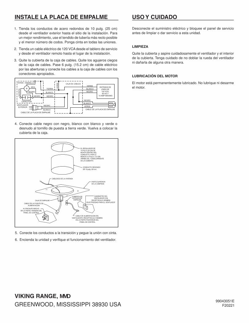
1. Tienda los conductos de acero redondos de 10 pulg. (25 cm)desdeelventiladorexteriorhastaelsitiodelainstalación.Paraunmejorrendimiento,useeltendidodetuberíamásrectoposibleyelmenornúmerodecodos.Pongacintaentodaslasuniones.
2. Tiendauncableeléctricode120VCAdesdeeltablerodeservicioydesdeelventiladorremotohastaellugardelainstalación.
3. Quitelacubiertadelacajadecables.Quitelosagujerosciegosdelacajadecables.Pase6pulg.(15.2cm)decableeléctricoporlasaberturasyconecteloscablesalacajadecablesconlosconectoresapropiados.
VIKING RANGE, MMDgREENWOOD,mISSISSIPPI38930USA
4. Conecte cablenegro connegro, blanco conblanco y verdeodesnudoaltornillodepuestaatierraverde.Vuelvaacolocarlacubiertadelacaja.
5. Conectelosconductosalatransiciónypeguelauniónconcinta.
6. Enciendalaunidadyverifiqueelfuncionamientodelventilador.
INSTALE LA PLACA DE EMPALME USO Y CUIDADO
Desconecteelsuministroeléctricoybloqueeelpaneldeservicioantesdelimpiarodarservicioaestaunidad.
LIMPIEZA
Quitelacubiertayaspirecuidadosamenteelventiladoryelinteriordelacubierta.Tengacuidadodenodoblarlaruedadelventiladornidañarladealgunaotramanera.
LUBRICACIÓN DEL MOTOR
Elmotorestápermanentementelubricado.Nolubriquenidesarmeelmotor.