monitoring of onshore and offshore pipelines using guided...
TRANSCRIPT

Monitoring of onshore and
offshore pipelines using
Guided Waves
A. Demma
Bergen, Norway
June 2012

Guided Ultrasonics Ltd. -
Milestones - technology

3 Guided Ultrasonics Ltd. -
GWT basics

GWT screening
Transducer
Metal structure
Inspected Area
Transducer Ring
Inspected area Inspected area
UT
GWT

Reflection from a Feature (such as corrosion)
When the guided wave hits a change in cross section (or
impedance), it reflects back toward the transducer
Transducer
Structure

Cross Section Change
The dark grey
Section represents the
Cross-sectional area
Typical targets are corrosion and erosion

System Components (screening)
Wavemaker G4
Transducers
Ring
Lemo Cables

Position of Ring
Decay Curves Corrosion is indicated
by large red component
Iconic representation
of identified features
Forward Backward
Series of Welds

-24dB
0.0 5.0 10.00
90
180
270
360
Angle
(deg)
0.0 5.0 10.00.0
0.5
1.0
1.5
2.0
Distance (m)
Am
p (
Lin
ear)
+F5
+F4
+F3
+F2
+F1
-F1
-F2
Guided Waves (unrolled pipe view)

10 Guided Ultrasonics Ltd. -
gPIMS monitoring

gPIMS Monitoring
Guided Wave Permanently Installed Monitoring System

g-PIMS principle
Inspected area Inspected area
GWT Transducer Ring
13 Guided Ultrasonics Ltd. - 12/06/2012
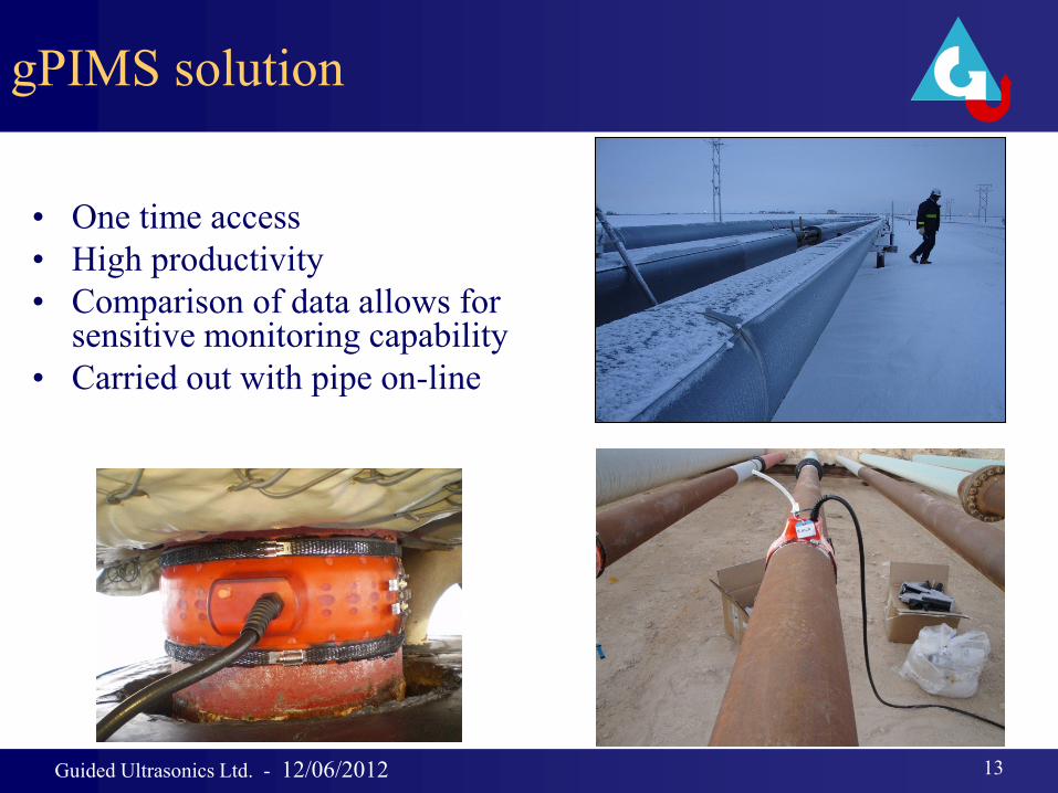
gPIMS solution
• One time access
• High productivity
• Comparison of data allows for sensitive monitoring capability
• Carried out with pipe on-line
Guided Ultrasonics Ltd. -
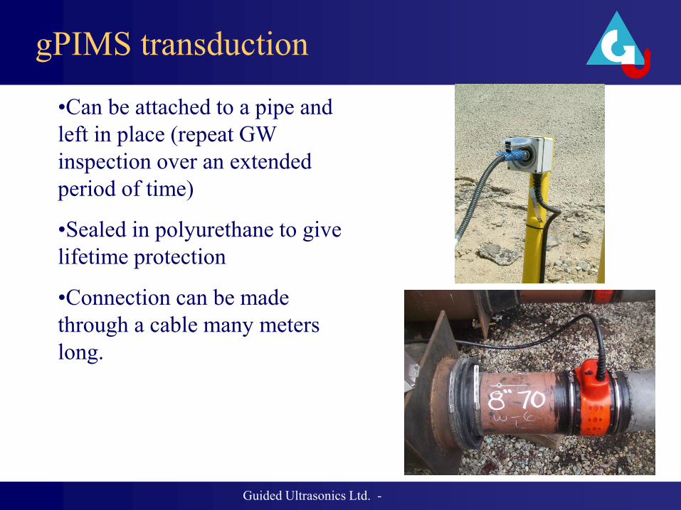
gPIMS transduction
•Can be attached to a pipe and
left in place (repeat GW
inspection over an extended
period of time)
•Sealed in polyurethane to give
lifetime protection
•Connection can be made
through a cable many meters
long.

15 Guided Ultrasonics Ltd. - 12/06/2012
G-PIMS unit
Wavemaker G3/G4 fully compatible with g-
PIMS rings.

Guided Ultrasonics Ltd. - Rev 1 (Aug 2010) -
• Bare pipes
• Buried pipes
• Road crossings
• Offshore risers
• Subsea lines
• Lines in contaminated or high risk areas
Example locations
Guided Ultrasonics Ltd. -
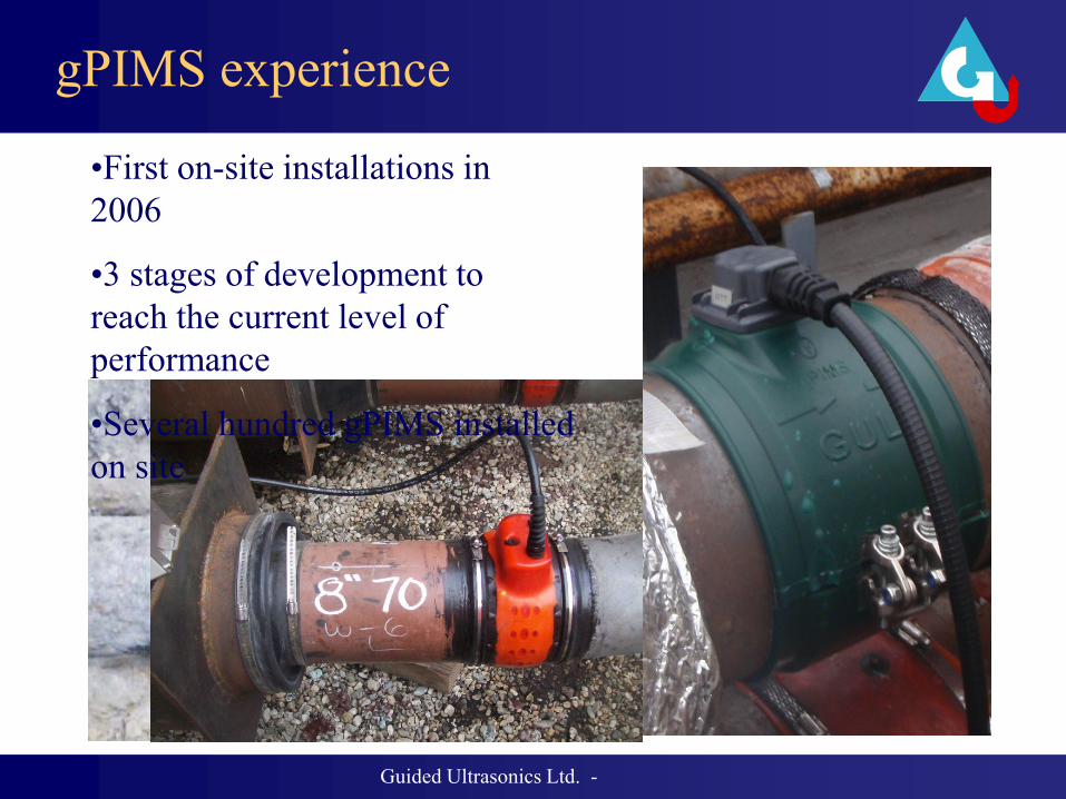
gPIMS experience
•First on-site installations in
2006
•3 stages of development to
reach the current level of
performance
•Several hundred gPIMS installed
on site

Current Limitations
• Pipe operating temperature -40°C to +90 °C
• Install temperature 10°C to +70°C
• Pipe size 6-24” for standard install
• Almost any size out side this range by custom
moulding
• Standard cable length up to 25m, up to 200m
cable possible.

gPIMS
Performance

Guided Ultrasonics Ltd. -
Results comparison with standard rings
Result using G-PIMS collar
(before
back fill)
Result using standard collar
-20.0 -10.0 0.0 10.0
10
5
2.5
1
0.5
0.25
Distance (m)
G3
11
#3
59
0 (
mV
)
-20.0 -10.0 0.0 10.0
10
5
2.5
1
0.5
0.25
G3
11
#3
59
7 (
mV
)
-F1-F2-F3-F4 +F1+F2 +F3-F1-F2-F3-F4 +F1+F2 +F3
Result from buried 8” line

Test pipe for sensitivity to change demo

Guided Ultrasonics Ltd. -
Sensitivity to change
2.5 3.0 3.5 4.0
0.0
1.0
2.0
3.0
Distance (m)
Am
p (
Lin
ear)
+F1 +F2
baseline
0.5% CSC
0.75% CSC 1% CSC

Stability of results
-10.0 -8.0 -6.0 -4.0 -2.0 0.0 2.0
60
50
25
10
5
2.5
1
Distance (m)
Am
p (
mV
)
-F1-F2-F3-F4-F5 +F1
Exposed test sample, results 12 months apart

Onshore
gPIMS case study

Case Study: Cased Crossing pipes
•G-PIMS installed on pipes at a cased road crossing
position prior to back filling. Monitoring tests can be
performed without expensive excavations in the future.

Results from cased section of previous slide
• Ø12”, Pipe 146
• Ø14”, Pipe 140 -1
8dB
-60 -40 -20 012
9
6
3
12
Clo
ck
-60 -40 -20 00.0
2.0
4.0
6.0
8.0
Distance (ft)
Am
p (
Lin
ear)
-F1
-F2
Sup
por
t
-F4
-F5
-F6
Sup
por
t
-F7
+F1
-18d
B
-60 -40 -20 012
9
6
3
12
Clo
ck
-60 -40 -20 00.0
5.0
10.0
15.0
20.0
25.0
Distance (ft)
Am
p (
Lin
ear)
-F1
-F2
-F3
-F4
-F5
-F6
+F1

Case study: buried pipe
• 24” buried line in tank farm
• G-PIMS installed on buried
section beneath instrument
• Connection box on yellow post

Result from buried section of previous slide
-18d
B
-5.0 0.0 5.0 10.0 15.00
90
180
270
360A
ngle
(deg)
-5.0 0.0 5.0 10.0 15.00.0
0.5
1.0
1.5
2.0
Distance (m)
Am
p(m
V)
+F1 +F2 +F3 +F4 +F5-F2-F1-F3

Offshore
gPIMS case study

Riser install - 2008
Guided Ultrasonics Ltd. - Rev 1 (Aug 2010)
-60 -40 -20 00.0
5.0
10.0
15.0
20.0
G3-
163#
1125
(Lin
ear)
-60 -40 -20 00.0
5.0
10.0
15.0
20.0
G3-
16#3
957
(Lin
ear)
-60 -40 -20 00.0
5.0
10.0
15.0
20.0
Distance (m)
G3-
116#
1042
(Lin
ear)
Flange+CaissonWeldWater levelWeldWeldWeldWeldSea bedWeld
Flange+CaissonWeldWater levelWeldWeldWeldWeldSea bedWeld
Flange+CaissonWeldWater levelWeldWeldWeldWeldSea bedWeld
a) Old style RA-PIMS installed on North Sea riser 2008. b) Cased riser gave good range, sensitivity and repeatability over successive years. c) Advanced data subtraction gives significant improvement in sensitivity.
a) b)
c)

31 Guided Ultrasonics Ltd. - 12/06/2012
-10.0 0.0 10.0 20.00.0
5.0
10.0
15.0
Distance (m)
Am
p (
Lin
ear)
-F1
-F2
-F3
+F1
+F2
+F3
+F4
+F5
+F6
gP
IMS
Monito
ring R
esu
lt
Subsea gPIMS
Pipe coated with 3LPE
Conclusions
• Monitoring is providing new solution to old inspection
problems
• Experience gained during past years enables high confidence
on performance of gPIMS
• This approach is low risk, low cost and highly efficient

Questions
• Thank You!