ncrp review of nasa space radiation operations€¦ · 06/12/1999 · tld-methods. method/technique...
TRANSCRIPT
Passive Dosimetry: Area and Crew Monitoring
Edward Semones, [email protected]
Lyndon B. Johnson Space Center
NCRP Review of NASA Space Radiation Operations
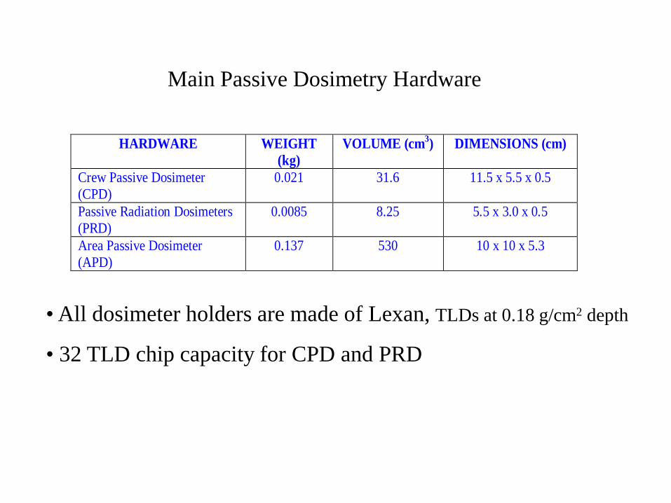
HARDWARE WEIGHT(kg)
VOLUME (cm3) DIMENSIONS (cm)
Crew Passive Dosimeter(CPD)
0.021 31.6 11.5 x 5.5 x 0.5
Passive Radiation Dosimeters(PRD)
0.0085 8.25 5.5 x 3.0 x 0.5
Area Passive Dosimeter(APD)
0.137 530 10 x 10 x 5.3
Main Passive Dosimetry Hardware
• All dosimeter holders are made of Lexan, TLDs at 0.18 g/cm2 depth
• 32 TLD chip capacity for CPD and PRD
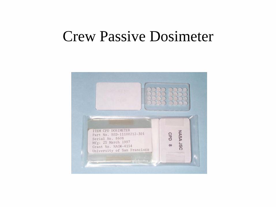
Crew Passive Dosimeter

Passive Radiation Dosimeter
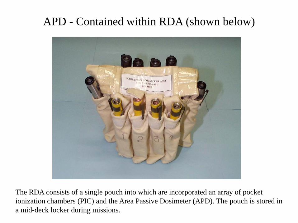
APD - Contained within RDA (shown below)
The RDA consists of a single pouch into which are incorporated an array of pocket ionization chambers (PIC) and the Area Passive Dosimeter (APD). The pouch is stored in a mid-deck locker during missions.

New Dosimeter Design
• This replaces CPD (Crew Passive Dosimeter) and PRD (Passive Radiation Dosimeter)
Note: Passive Radiation Dosimeter will now be called Radiation Area Monitor (RAM)
• All dosimeter holders are made of Lexan - TLDs at 0.18 g/cm2 depth
• New CPD and RAM will have 24 TLD chip capacity

Instruments/Equipment
• Harshaw 5500 Automatic TLD Readers (2)– hot N2 Gas Heating
• Harshaw 3500 Manual TLD Reader (1)– Planchet Heating
• Cs-137 Calibration Range– (JL Shepard, 600 mCi), Ion chambers, Electrometers
• Annealing Ovens (2)• Vacuum Tweezers (4)

TLD Material
• TLD-100 - LiF:Mg,Ti (7.5% 6Li and 92.5% 7Li)
• TLD-600 - LiF :Mg,Ti (95.6% 6Li and 4.4% 7Li)
• TLD-700 - LiF :Mg,Ti (99.93% 7Li and 0.07% 7Li)
• TLD-300 - CaF2:Tm
Chip size used = 3.2 mm x 3.2 mm x 0.9 mm

TLD-MethodsMethod/Technique Material
TLD-100,600,700 TLD-300Annealing 400 °C for 1 hr
followed by slow coolto room temp
400 °C for 1 hrfollowed by 100 °C for
2 hrPre-readout annealing 100 °C for 30 min 100 °C for 30 min
Reader Harshaw 5500 Harshaw 5500
Temperature Range 100 – 400 °C 100 – 400 °C
Heating Rate 6 °C s-1 6 °C s-1
TL Evaluation Method Region of Interest(ROI)
Region of Interest(ROI)

Calibration
• Irradiation with Cs-137– (662 keV photons) - Air Kerma = 2 mGy/h
• Performed according to ANSI N13.11-1993– With the exception of phantom - we irradiate
dosimeters free-in-air
• Calibration in terms of free-space absorbed dose to tissue results in a calibration factor used to convert glow curve ROIs.

TLD-100 Glow Curve

TLD-300 Glow Curve

Timeline
L-30D Select/Anneal TLD Material
L-14D Dosimetry Delivered to USA/FCE
Irradiation of Calibration Dosimeters
L A U N C H
L A N D I N G
R+5D Dosimetry Received at USA/FCE
R+7D Dosimetry Received at SRDLab
R+7D - R+20D
Dosimetry Readout - Flight, Controls,
Calibration
Prepare Work Start
Dosimetry Report Generated - No Later Than R+30D

PRD Locations in the Shuttle
(DLOCs)

Location of Hardmounted Shuttle TEPCwith location of DLOC2 for Reference

USLAB
NODE 1
Node 1- 1 - Aft end, near hatch close out panelNode 1- 2 - Central area, perhaps on light barNode 1- 3 - Forward, close-out panel upper port wallNode 1- 4 - Reserved
3
1
2
Actual

NODE 1 RAM - LOCATION 2 INSTALLATION

NODE 1RAM - LOCATION 1 INSTALLATIONCLOSE-UP

US LAB
1
2
3
4
Proposed locationsLab 1 - Stand off LAX-3 below Rack 5Lab 2 - Stand off LAX-1 below Rack 2Lab 3 - Near Lab window, outside hullLab 4 - Forward wall near hatch Lab 5 - ReservedLab 6 - Reserved
5 *
Under Evaluation

Intercomparisons/Accelerator Calibrations
Particle Beam Energy/nucleon (MeV/amu)p 250p 250p 200p 200p 149p 149p 70p 70p 70p 70
He 150He 150C 290C 290Si 490Si 490
Fe - BNL 1000Fe- BNL 1000
Fe 500Fe 500

High-LET Irradiations
0.100
1.000
0.1 1.0 10.0 100.0 1000.0
LET (keV/um)
Rel
ativ
e D
ose
Effic
ienc
y
HIMAC/BNL
LOMA LINDA

Dosimetry Record Keeping
Edward Semones, [email protected]
Lyndon B. Johnson Space Center
NCRP Review of NASA Space Radiation Operations

NOTE: This page is subject to Privacy Act of 1974
JSC Space Radiation Dosimetry ReportDosimetry Laboratory STS-103 Date: 12-6-99
Page 2 of 2
Dose Values from TLD DosimetersLow-LET (Linear Energy Transfer) Component
Crew Passive Dosimeters (CPD)
Detector: TLD-100 at Avg. CPD Dose (mrad) Max. CPD Dose (mrad) Min. CPD Dose (mrad)Depth of 0.18 g/cm2
Detector: TLD-100 at 0.18 gm/cm2 Ground Dose Control (mrad): ±Dosimeter Crew Member EVA Dose (mrad)
CPD1 CDR Curtis L. Brown N ±CPD2 PLT Scott J. Kelly N ±CPD3 MS1 Steven L. Smith Y ±CPD4 MS2 Jean-Francois Clervoy (France/ESA) N ±CPD5 MS3 John M. Grunsfeld Y ±CPD6 MS4 C. Michael Foale Y ±CPD7 MS5 Claude Nicollier (Switzerland/ESA) Y ±
Comments: Stated uncertainty represents measurement precision, one sigma of the mean, rather than absoluteaccuracy.
NOTE: This page is subject to Privacy Act of 1974
Dosimetry Report

ISO 9001 Quality Records
• Dosimetry Reports
• Raw Data - All Glow Curves
• Calibration Records -Instruments + Calibration Field
• Task Performance Sheets (TPS) - all configuration information (types/quantities of detectors)
NOTE: This page is subject to Privacy Act of 1974
JSC Space Radiation Dosimetry ReportDosimetry Laboratory STS-103 Date: 12-6-99
Page 2 of 2
Dose Values from TLD DosimetersLow-LET (Linear Energy Transfer) Component
Crew Passive Dosimeters (CPD)
Detector: TLD-100 at Avg. CPD Dose (mrad) Max. CPD Dose (mrad) Min. CPD Dose (mrad)Depth of 0.18 g/cm2
Detector: TLD-100 at 0.18 gm/cm2 Ground Dose Control (mrad): ±Dosimeter Crew Member EVA Dose (mrad)
CPD1 CDR Curtis L. Brown N ±CPD2 PLT Scott J. Kelly N ±CPD3 MS1 Steven L. Smith Y ±CPD4 MS2 Jean-Francois Clervoy (France/ESA) N ±CPD5 MS3 John M. Grunsfeld Y ±CPD6 MS4 C. Michael Foale Y ±CPD7 MS5 Claude Nicollier (Switzerland/ESA) Y ±
Comments: Stated uncertainty represents measurement precision, one sigma of the mean, rather than absoluteaccuracy.
NOTE: This page is subject to Privacy Act of 1974

Passive Dosimetry Report combined with Shuttle TEPC resultsNOTE: This page is subject to Privacy Act of 1974
JSC Space Radiation Dosimetry ReportDosimetry Laboratory STS-103 Date: 12-6-99
Page 2 of 2
Dose Values from TLD DosimetersLow-LET (Linear Energy Transfer) Component
Crew Passive Dosimeters (CPD)
Detector: TLD-100 at Avg. CPD Dose (mrad) Max. CPD Dose (mrad) Min. CPD Dose (mrad)Depth of 0.18 g/cm2
Detector: TLD-100 at 0.18 gm/cm2 Ground Dose Control (mrad): ±Dosimeter Crew Member EVA Dose (mrad)
CPD1 CDR Curtis L. Brown N ±CPD2 PLT Scott J. Kelly N ±CPD3 MS1 Steven L. Smith Y ±CPD4 MS2 Jean-Francois Clervoy (France/ESA) N ±CPD5 MS3 John M. Grunsfeld Y ±CPD6 MS4 C. Michael Foale Y ±CPD7 MS5 Claude Nicollier (Switzerland/ESA) Y ±
Comments: Stated uncertainty represents measurement precision, one sigma of the mean, rather than absoluteaccuracy.
NOTE: This page is subject to Privacy Act of 1974
Doses calculated from the Linear data (512 channels)
SHUTTLE GCR TRAPPED TOTALDose (µ Gray) 1066.615 629.924 1696.539Dose Equivalent (60)(µ Sievert)
5490.735 1215.849 6706.584
Dose Equivalent (26)(µ Sievert)
4468.452 1251.759 5720.211
Particles count 1972984.215 1205299.785 3178284.000Time (minutes) 12118.000 688.000 12806.000Dose (µ Gray/day) 119.938 70.833 190.771Dose Equivalent (60)/day(µ Sievert/day)
617.418 136.719 754.137
Dose Equivalent (26)/day(µ Sievert/day)
502.465 140.757 643.222