network automation - clnv.s3.amazonaws.com · network automation and programmability for service...
TRANSCRIPT


Network Automationand Programmabilityfor Service Providers
Ahmed Abeer, Technical Marketing Engineer
Nicolas Breton, Manager Product Marketing
BRKSPG-2210

© 2018 Cisco and/or its affiliates. All rights reserved. Cisco Public
Cisco Spark
Questions? Use Cisco Spark to communicate with the speaker after the session
1. Find this session in the Cisco Live Mobile App
2. Click “Join the Discussion”
3. Install Spark or go directly to the space
4. Enter messages/questions in the space
How
cs.co/ciscolivebot#BRKSPG-2210

• Programmable network
• Automatic Device Provisioning
• Design the programmable underlay
• Building a Programmable Transport
• Network Topology Discovery
• Compute & Program the Transport Path
• Next Step: Service Enablement
• Summary
• Conclusion
Agenda

© 2018 Cisco and/or its affiliates. All rights reserved. Cisco Public
Session Objectives
• To understand how programmability impacts existing network designs.
• To learn techniques and tips to design programmable underlay and overlay.
• To learn network automation and discovery.
• To learn concrete design recommendations.
5BRKSPG-2210

Programmable Network

© 2018 Cisco and/or its affiliates. All rights reserved. Cisco Public 7BRKSPG-2210
Trends in the Service Provider Transport
• Scale the access within a domain• Number of nodes and services increasing
• Bandwidth growth 10GE -> 100G
• Traffic load optimization
• Agile service deployment across domains• End to End service deployments
• Virtualization• Virtual CPE, Virtual NID
Access and Aggregation
At the same time, keep the same Services KPI’s
OAM, Traffic load management, Transparent Node and Service insertion
Core
Access Domain A
Access Domain B
Access Domain C

© 2018 Cisco and/or its affiliates. All rights reserved. Cisco Public 8BRKSPG-2210
Network Programmability What is changing in the network?
Core
Access Domain A
Access Domain B
Access Domain C
Core
Access Domain A
Access Domain B
Access Domain C
NMSService
Assurance
Traditional Programmatic Approach
Orchestration
WAN Optimization Engine
Path Computation
Topology Discovery
ProgrammableInterfaces
Segment Routing
OSS BSS
IP/MPLS/ L2
SNMP
CLI
XR Transport Controller
Open Source

© 2018 Cisco and/or its affiliates. All rights reserved. Cisco Public 9BRKSPG-2210
Programmable Network – New Operation Model
Model Driven Programmable InterfacesProgrammatic
Interfaces
Open
Protocols
Configuration
ManagementTraffic
Engineering
Operational
State
API
APIC EMIOS XR XML
NetconfRestconf
Protocols
Telemetry PCEPBGP-LS

Automatic Device Provisioning“The Day 0 Challenge”

© 2018 Cisco and/or its affiliates. All rights reserved. Cisco Public
SD-WAN
IoT
5GLarge
number of devices to bring up
Devices distributed in different physical locations
Expected to be
service ready on bringup
The Day 0 Challenges
•
11BRKSPG-2210
Simplify Day 0 device
deployments
Service-
Ready
Infrastructure
Rapid Nodes and
Service
deployments

© 2018 Cisco and/or its affiliates. All rights reserved. Cisco Public
ZTD – Two Different Deployment Scenarios
• Routers are connected to a
management network via out-of-band
management port
• Popular in Data Center, Enterprise,
and Web customers
• There is no dedicated management
network. Routers are managed via
in-band, the same as user data
network
• Typical deployment in the SP
Access/Metro
1
2
Servers
(DHCP/HTTP)
“in-band”
management
L3 linkL3 link
L3 linkL3 link
L2 EVC
Sub-int
“out-of-band”
Management
network
Servers
(DHCP/NMS)
BRKSPG-2210 12

© 2018 Cisco and/or its affiliates. All rights reserved. Cisco Public
ZTD requirements
Baseline requirements across both
deployment scenarios
• No pre-staging required
• DHCP for management IP address
• Configuration download
• Image upgrade/downgrade
• Connection to the NMS
Baseline requirement for “in-band
management” deployment scenario
• Auto L3 adjacency configuration in any
topology
• L2 VLAN auto-discovery
Value added requirements
• Robust connection to NMS
• Secure
• Multi-vendor support
• Configuration template
Layer 2 MPLS
L3 Network MPLS
MPLS
Layer 2
Layer 2
Layer 2 Ring Topology
Hub & Spoke Network
Compound Topology
MPLS MPLSLayer 3
Layer 3 Ring Topology
BRKSPG-2210 13

© 2018 Cisco and/or its affiliates. All rights reserved. Cisco Public
Option 1: Provisioning from the DHCP Server
DHCP
HTTP
NSO
Get Script
Provision.py
1
3
4
Server
Initiated
Device boot up and initiate a DHCP Discover
DHCP server provides a script using “bootfilname” (option 67)
Upon commit DHCP server:Registers device to NSO using REST
Asks NSO to retrieve RSA keys from device
Device Downloads scripts from HTTP server.
Scripts is executed on the device.
Once registered, the script perform a sync from the NSO server
1
2
2
3
4
BRKSPG-2210 14

© 2018 Cisco and/or its affiliates. All rights reserved. Cisco Public
Option 1: NSO InitiatedWhen Device do not run any Script or Compute
DHCP Request ( Broadcast)
DHCP Request ( Unicast) DHCP
Server Python ScriptNotification address leased
DHCP Response ( Unicast)DHCP Option 67
1
2
1
2
33 NSO
4
HTTP Request
HTTP File: Script
0 Run ZTP.sh
5 Run ScriptEnables: SSH, User name, Password, Netconf
6 NSO OperationsSync from, Get Serial Number, Apply Day 1 Configuration
3 IP Address, Default GW Bootfile name
Config
Config
Config
Synch
Server
Initiated
NSO Registration
BRKSPG-2210 15

© 2018 Cisco and/or its affiliates. All rights reserved. Cisco Public
Option 2: Provisioning from the Device
DHCP
HTTP
NSO
Get Script
Provision.py
1
2
3-4
Device
Initiated
1
2
3
4
Device boot up and initiates a DHCP Discover
DHCP server provides a script using “boot-file-
name” (option 67)
Device Downloads scripts from HTTP/FTP
server
Scripts is executed on the device and registers
to NSO using REST/RESTCONF API
Once registered, the script perform a sync from
the NSO serverBRKSPG-2210 16
© 2018 Cisco and/or its affiliates. All rights reserved. Cisco Public
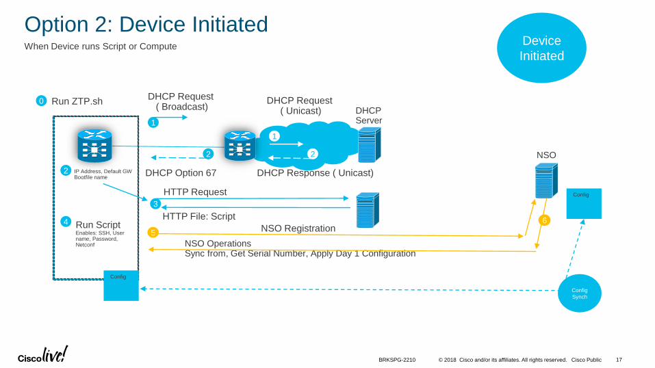
Option 2: Device Initiated
DHCP Request ( Broadcast)
DHCP Request ( Unicast) DHCP
Server
DHCP Response ( Unicast)DHCP Option 67
1
1
22 NSO
3
HTTP Request
HTTP File: Script
0 Run ZTP.sh
4 Run ScriptEnables: SSH, User name, Password, Netconf
5
NSO OperationsSync from, Get Serial Number, Apply Day 1 Configuration
2 IP Address, Default GW Bootfile name
Config
Config
Config
Synch
6
When Device runs Script or Compute Device
Initiated
NSO Registration
BRKSPG-2210 17

© 2018 Cisco and/or its affiliates. All rights reserved. Cisco Public
Different download method with IOS XE versus XR
DHCP
server
IOS XR IOS XE
Boot BootUp Script Yes Separate
daemon
DHCP DHCP Option 67 150
Download
Options
Download
Method
HTTP server TFTP server
Download and
run Script
Yes No
Download
Configuration
No Yes
NSO
NSO Initiated Yes Yes
Device Initiated Yes No
Option 67
DHCP
serverOption
150
Script
HTTP
server Configuration
TFTP
server
Script
NSO
ScriptNSO
ScriptNSO
XR XE
BRKSPG-2210 18

Designing the Programmable UnderlayStep 1: Build a Programmable Transport

© 2018 Cisco and/or its affiliates. All rights reserved. Cisco Public
Why Segment Routing?
• More Control and Programmable
• Segment Routing Labels are assigned manually or programmed
• Simplifies the Control plane stack.
• Extension to IGP’s ( ISIS , OSPF)
• Seamless migration
• SR mapping server
• Traffic Engineering: SR-TE
• Single touch point at the headend
• Flexibility to optimize traffic load
• Control the path at very granular level
20BRKSPG-2210
Programmable MPLS
Domain A Domain C
ABR 1 ABR 2
Program MPLS labelsService labelSR-TE path
CLI>
OR
Head-End
Domain B

© 2018 Cisco and/or its affiliates. All rights reserved. Cisco Public 21BRKSPG-2210
Unified MPLS vs Segment RoutingIntra Domain
LDP/IGP
Programmable MPLSUnified MPLS
ISIS-SR
MPLS Labels Unifed MPLS Segment Routing
Transport Labels Dynamic Label allocation (LDP) Programmed or cli
Service Labels Dynamic Label allocation (LDP) Programmed or cli
Program MPLS labels:Prefix SIDService Label
Prefix SIDsLDP LDP
LDPLDP
PWPW
LDP
CLI>
OR
Service Label

© 2018 Cisco and/or its affiliates. All rights reserved. Cisco Public 22BRKSPG-2210
Unified MPLS vs Segment RoutingInter Domain
Programmable MPLSUnified MPLS
IGP / LDP IGP / LDP
BGP-LU
2
31
LDP Label
BGP Label
Service Label
Swap
32
3
32
Swap
SR TE
IGP IGP
4
2
Service Label
3 Destination Label
4
3
4
3
2 TE Label 3 4
Program MPLS labelsPrefix SIDService Label
OR
TE FRR / Remote LFA
Domain A Domain C
ABR 1 ABR 2
Head-End
Domain B
CLI>
Domain A Domain C
ABR 1 ABR 2
Domain B
IGP / LDPIGP
2 Next Hop Label
1 ABR1 Label
ABR 2 Label2 Swap

© 2018 Cisco and/or its affiliates. All rights reserved. Cisco Public 23BRKSPG-2210
Reference TopologyPrefix SID
Loopback IP
Link Addresses
Interfaces

© 2018 Cisco and/or its affiliates. All rights reserved. Cisco Public
Segment Routing Configuration
IGP - OSPFRP/0/0/CPU0:A11#config t
segment-routing
global-block 16000 23999
!
router ospf 1
router-id 1.1.1.11
segment-routing mpls
segment-routing forwarding mpls
fast-reroute per-prefix
fast-reroute per-prefix ti-lfa enable
address-family ipv4
area 0
interface Loopback0
prefix-sid index 11
!
interface GigabitEthernet0/0/0/1
network point-to-point
!
interface GigabitEthernet0/0/0/0
network point-to-point
!
commit
RP/0/0/CPU0:A21#config t
segment-routing
global-block 16000 23999
!
router isis 2
is-type level-2-only
net 49.0001.0000.0000.0021.00
address-family ipv4 unicast
metric-style wide
segment-routing mpls
!
interface Loopback0
address-family ipv4 unicast
prefix-sid index 21
!
router isis 2
!
address-family ipv4 unicast
!
interface GigabitEthernet0/0/0/0
point-to-point
address-family ipv4 unicast
fast-reroute per-prefix
fast-reroute per-prefix ti-lfa
!
[SNIP…]
!
commit
IGP - ISISA21A11
SRGB Block
Enable Segment
Routing
Configure Prefix SID
(Node SID)
Link Protection (TI-
LFA)
SRGB Block
Enable Segment
Routing
Configure Prefix SID
(Node SID)
Link Protection (TI-
LFA)
Configure

© 2018 Cisco and/or its affiliates. All rights reserved. Cisco Public
Segment Routing Validation
Control PlaneRP/0/0/CPU0:A21#sh isis neighbors
Mon Jan 29 02:07:57.650 UTC
IS-IS 2 neighbors:
System Id Interface SNPA State Holdtime Type IETF-
NSF
A22 Gi0/0/0/1 *PtoP* Up 23 L2 Capable
PE121 Gi0/0/0/0 *PtoP* Up 22 L2 Capable
Total neighbor count: 2
!
RP/0/0/CPU0:A21#show mpls label table label 16000 detail
Thu Feb 23 21:30:43.546 UTC
Table Label Owner State Rewrite
----- ------- ------------------------------- ------ -------
0 16000 ISIS(A):2 InUse No
(Lbl-blk SRGB, vers:0, (start_label=16000, size=8000)
!
RP/0/0/CPU0:A21#show isis route 3.3.3.122/32 detail
Mon Jan 29 02:08:17.650 UTC
L2 3.3.3.122/32 [30/115] medium priority
via 21.121.0.121, GigabitEthernet0/0/0/0, PE121, SRGB Base:
16000, Weight: 0
src PE122.00-00, 3.3.3.122, prefix-SID index 122, R:0 N:1 P:0
E:0 V:0 L:0
RP/0/0/CPU0:A21#show route 3.3.3.122/32 detail
Mon Jan 29 02:06:47.650 UTC
Routing entry for 3.3.3.122/32
Known via "isis 2", distance 115, metric 30, labeled SR, type level-2
Installed Jan 25 04:13:15.316 for 3d21h
Routing Descriptor Blocks
21.121.0.121, from 3.3.3.122, via GigabitEthernet0/0/0/0, Protected
Route metric is 30
Label: 0x3efa (16122)
Tunnel ID: None
Binding Label: None
Extended communities count: 0
Path id:1 Path ref count:0
NHID:0x3(Ref:10)
Backup path id:65
21.22.1.22, from 3.3.3.122, via GigabitEthernet0/0/0/1, Backup
(Local-LFA)
Route metric is 40
Label: 0x3efa (16122)
Tunnel ID: None
Binding Label: None
Extended communities count: 0
Path id:65 Path ref count:1
NHID:0x4(Ref:10)
Route version is 0xd (13)
Local Label: 0x3efa (16122)
[SNIP]
Control PlaneA21A21
Primary Path (TI-LFA
Protected Link)
Backup Path
ISIS Neighbors
ISIS Validation Only
SRGB Block
Route to Core
SR Label

© 2018 Cisco and/or its affiliates. All rights reserved. Cisco Public
Segment Routing Validation
Forwarding PlaneRP/0/0/CPU0:A21#show cef 3.3.3.122/32 detail
Mon Jan 29 02:10:35.815 UTC
3.3.3.122/32, version 104, labeled SR, internal 0x1000001 0x81 (ptr
0xa134e63c) [1], 0x0 (0xa1333878), 0xa28 (0xa18190d4)
Updated Jan 25 04:13:15.336
local adjacency 21.121.0.121
Prefix Len 32, traffic index 0, precedence n/a, priority 1
gateway array (0xa1299a48) reference count 3, flags 0x500068,
source rib (7), 0 backups
[2 type 5 flags 0x8401 (0xa15ef5f0) ext 0x0 (0x0)]
LW-LDI[type=5, refc=3, ptr=0xa1333878, sh-ldi=0xa15ef5f0]
gateway array update type-time 1 Jan 25 04:13:15.336
LDI Update time Jan 25 04:13:15.336
LW-LDI-TS Jan 25 04:13:15.336
via 21.121.0.121/32, GigabitEthernet0/0/0/0, 10 dependencies,
weight 0, class 0, protected [flags 0x400]
path-idx 0 bkup-idx 1 NHID 0x0 [0xa1833544 0x0]
next hop 21.121.0.121/32
local label 16122 labels imposed {16122}
via 21.22.1.22/32, GigabitEthernet0/0/0/1, 10 dependencies,
weight 0, class 0, backup (Local-LFA) [flags 0x300]
path-idx 1 NHID 0x0 [0xa171c250 0x0]
next hop 21.22.1.22/32
local adjacency
local label 16122 labels imposed {16122}
[SNIP]
RP/0/0/CPU0:A21#show mpls forwarding labels 16122
Mon Jan 29 02:15:30.415 UTC
Local Outgoing Prefix Outgoing Next Hop Bytes
Label Label or ID Interface Switched
------ ----------- ------------------ ------------ --------------- ------------
16122 16122 SR Pfx (idx 122) Gi0/0/0/0 21.121.0.121 957044
16122 SR Pfx (idx 122) Gi0/0/0/1 21.22.1.22 0 (!)
!
RP/0/0/CPU0:A21#ping 3.3.3.122 source 2.2.2.21
Mon Jan 29 02:16:11.032 UTC
Type escape sequence to abort.
Sending 5, 100-byte ICMP Echos to 3.3.3.122, timeout is 2 seconds:
!!!!!
Success rate is 100 percent (5/5), round-trip min/avg/max = 9/9/9 ms
!
RP/0/0/CPU0:A21#traceroute 3.3.3.122 source 2.2.2.21
Mon Jan 29 02:16:33.810 UTC
Type escape sequence to abort.
Tracing the route to 3.3.3.122
1 21.121.0.121 [MPLS: Label 16122 Exp 0] 19 msec 9 msec 9 msec
2 121.122.2.122 9 msec * 9 msec
Forwarding PlaneA21A21
Primary Path &
Label Imposed
Traceroute
ISIS Validation Only
Backup Path &
Label Imposed
Ping
Primary & Backup Path

Designing the Programmable UnderlayStep 2: Network Topology Discovery

© 2018 Cisco and/or its affiliates. All rights reserved. Cisco Public
BGP-LS Overview
• Build TED for Multi-Domain Optimal Path Computation
• Scalable Solution is BGP, not IGP.
• BGP-LS is an address-family
• afi=16388, safi=71
• Defined to carry IGP link-state database via BGP
• Supports both IS-IS and OSPF
• Delivers topology information to outside agents
• Only one BGP-LS speaker required per domain
28BRKSPG-2210
Path Computation Element (PCE)
Domain A Domain C
ABR 1 ABR 2
Head-End
Domain B
CLI>
Traffic
Engineering
Database (TED)
PCE
BGP-LS

© 2018 Cisco and/or its affiliates. All rights reserved. Cisco Public 29BRKSPG-2210
XR Transport Controller (XTC)
• Multi-Domain Topology Collection
• Real-time reactive feed
• Computation
• Native SR Policy algorithms
• Applicable to Centralized (Controller) and Distributed (Router) deployments
An IOS XR-powered Stateful Path Computation Element (PCE)
Multi-Domain
Topology
North-Bound API
Computation
“Collection”
BGP-LS
ISIS / OSPF
“Deployment”
PCEP
WAE Custom app
XTC

© 2018 Cisco and/or its affiliates. All rights reserved. Cisco Public
XTC – Real-time Topology Feed
• XTC learns real-time topologies via BGP-LS and/or IGP
• BGP-LS is intended to carry link-state topology information
• Hence the name “LS” that stands for “Link State”
• BGP-LS has been extended multiple times in order to incorporate other types of topology information:
• SR Extensions
• Traffic Engineering Metric Extensions
• Egress Peer Engineering
• SR TE Policies
BRKSPG-2210 30

© 2018 Cisco and/or its affiliates. All rights reserved. Cisco Public
BGP Link State Configuration
• Common topology abstraction model
• IGP network modeled
• Three classes of objects
• Nodes
• Links
• prefixes
31BRKSPG-2210
BGP-LS Objects
• 11 nodes
• 29 links
• 98 prefixes
• 248 Paths

© 2018 Cisco and/or its affiliates. All rights reserved. Cisco Public
BGP Link State Device Configuration
IGP ConfigurationRP/0/0/CPU0:PE122#config t
!
router isis 3
distribute bgp-ls instance-id 3
!
RP/0/0/CPU0:PE122#sh run router isis 2
Mon Jan 29 04:18:22.432 UTC
router isis 2
is-type level-2-only
net 49.0001.0000.0000.0122.00
distribute link-state instance-id 2
address-family ipv4 unicast
segment-routing mpls
!
interface Loopback0
address-family ipv4 unicast
prefix-sid index 122
!
!
interface GigabitEthernet0/0/0/1
point-to-point
address-family ipv4 unicast
fast-reroute per-prefix
fast-reroute per-prefix ti-lfa
[SNIP]
RP/0/0/CPU0:PE122#sh run router bgp
Mon Jan 29 04:09:49.717 UTC
router bgp 1
bgp router-id 3.3.3.122
!
[SNIP]
!
neighbor-group epn
remote-as 1
update-source Loopback0
address-family ipv4 labeled-unicast
route-reflector-client
next-hop-self
!
!
neighbor 4.4.4.4
remote-as 1
update-source Loopback0
address-family ipv4 labeled-unicast
!
address-family link-state link-state
!
!
neighbor 2.2.2.21
use neighbor-group epn
!
[Output TRIMMED]
BGP ConfigurationPE122PE122
BGP ID
XR Transport
Controller (XTC)
Address
Enable BGP Link
State
Instance ID =
Domain ID
Domain 2
Configure
Specify BGP-LS
Neighbor

© 2018 Cisco and/or its affiliates. All rights reserved. Cisco Public
BGP Link State XTC Configuration
RP/0/0/CPU0:XTC-RR4#sh run router bgp
Mon Jan 29 04:07:50.050 UTC
router bgp 1
bgp router-id 4.4.4.4
address-family ipv4 unicast
table-policy fib
additional-paths receive
additional-paths send
additional-paths selection route-policy multipath
!
address-family link-state link-state
!
neighbor-group epn
remote-as 1
update-source Loopback0
address-family ipv4 labeled-unicast
route-reflector-client
!
address-family link-state link-state
!
neighbor 3.3.3.111
use neighbor-group epn
!
neighbor 3.3.3.112
use neighbor-group epn
!
[SNIP]
XTC-RR4
BGP ID
Enable Address
Family Link State
BGP-LS Neighbors
Configure

© 2018 Cisco and/or its affiliates. All rights reserved. Cisco Public
RP/0/0/CPU0:XTC-RR4#show bgp link-state link-state summary
Mon Jan 29 03:24:02.000 UTC
BGP router identifier 4.4.4.4, local AS number 1
BGP generic scan interval 60 secs
Non-stop routing is enabled
BGP table state: Active
Table ID: 0x0 RD version: 95
BGP main routing table version 95
BGP NSR Initial initsync version 95 (Reached)
BGP NSR/ISSU Sync-Group versions 0/0
BGP scan interval 60 secs
BGP is operating in STANDALONE mode.
Process RcvTblVer bRIB/RIB LabelVer ImportVer SendTblVer StandbyVer
Speaker 95 95 95 95 95 0
Neighbor Spk AS MsgRcvd MsgSent TblVer InQ OutQ Up/Down St/PfxRcd
3.3.3.111 0 1 2792 2758 95 0 0 1d21h 62
3.3.3.112 0 1 2792 2758 95 0 0 1d21h 62
3.3.3.121 0 1 2788 2758 95 0 0 1d21h 62
3.3.3.122 0 1 2788 2758 95 0 0 1d21h 62
34BRKSPG-2210
BGP Link State Verification
Neighbors:
3.3.3.111 62 Paths
3.3.3.112 62
3.3.3.121 62
3.3.3.122 62
Total = 62x4 = 248 Paths
BGP -LS Validation Only
XTC-RR4

© 2018 Cisco and/or its affiliates. All rights reserved. Cisco Public
RP/0/0/CPU0:XTC-RR4#show bgp link-state link-state
Mon Jan 29 03:24:49.337 UTC
BGP router identifier 4.4.4.4, local AS number 1
BGP generic scan interval 60 secs
Non-stop routing is enabled
BGP table state: Active
Table ID: 0x0 RD version: 95
BGP main routing table version 95
BGP NSR Initial initsync version 95 (Reached)
BGP NSR/ISSU Sync-Group versions 0/0
BGP scan interval 60 secs
Status codes: s suppressed, d damped, h history, * valid, > best
i - internal, r RIB-failure, S stale, N Nexthop-discard
Origin codes: i - IGP, e - EGP, ? - incomplete
Prefix codes: E link, V node, T IP reacheable route, u/U unknown
I Identifier, N local node, R remote node, L link, P prefix
L1/L2 ISIS level-1/level-2, O OSPF, D direct, S static/peer-node
a area-ID, l link-ID, t topology-ID, s ISO-ID,
c confed-ID/ASN, b bgp-identifier, r router-ID,
i if-address, n nbr-address, o OSPF Route-type, p IP-prefix
d designated router address
Network Next Hop Metric LocPrf Weight Path
*>i[V][L2][I0x2][N[c1][b0.0.0.0][s0000.0000.0021.00]]/328
3.3.3.121 100 0 i
* i 3.3.3.122 100 0 i
*>i[V][O][I0xb][N[c1][b0.0.0.0][a0.0.0.0][r1.1.1.11]]/376
3.3.3.111 100 0 i
i 3.3.3.112 100 0 i
[SNIP]
35BRKSPG-2210
BGP Link State Verification
Node
V= node
O= OSPF
N= local node
c= Confed ID/ ASN -- 1
b=bgp-id – 0.0.0.0
a=area-id -- 0.0.0.0
r=router-id -- 1.1.1.11
Check here for the
Prefix codes
BGP -LS Validation Only
XTC-RR4

© 2018 Cisco and/or its affiliates. All rights reserved. Cisco Public
* i 3.3.3.112 100 0 i
*>i[E][O][I0xb][N[c1][b0.0.0.0][a0.0.0.0][r3.3.3.112]][R[c1][b0.0.0.0][a0.0.0.0][r1.1.1.13]][L[i13.112.0.112][n13.112.0.13]]/792
3.3.3.111 100 0 i
* i 3.3.3.112 100 0 i
*>i[E][O][I0xb][N[c1][b0.0.0.0][a0.0.0.0][r3.3.3.112]][R[c1][b0.0.0.0][a0.0.0.0][r3.3.3.111]][L[i111.112.3.112][n111.112.3.111]]/792
3.3.3.111 100 0 i
* i 3.3.3.112 100 0 i
*>i[T][L2][I0x2][N[c1][b0.0.0.0][s0000.0000.0021.00]][P[p21.22.1.0/24]]/392
3.3.3.121 100 0 i
* i 3.3.3.122 100 0 i
*>i[T][L2][I0x2][N[c1][b0.0.0.0][s0000.0000.0021.00]][P[p21.121.0.0/24]]/392
3.3.3.121 100 0 i
• i 3.3.3.122 100 0 i
[SNIP]
!
*>i[T][O][I0xb][N[c1][b0.0.0.0][a0.0.0.0][r3.3.3.112]][P[o0x01][p111.112.3.0/24]]/480
3.3.3.111 100 0 i
* i 3.3.3.112 100 0 i
*>i[T][O][I0xb][N[c1][b0.0.0.0][a0.0.0.0][r3.3.3.112]][P[o0x01][p3.3.3.112/32]]/488
3.3.3.111 100 0 i
* i 3.3.3.112 100 0 i
Processed 94 prefixes, 248 paths
BGP Link State Verification
BGP -LS Validation Only
Link
E=link
N=node
c= Confed ID/ ASN -- 64496
b=bgp-id – 0.0.0.0
a=area-id -- 0.0.0.0
r=router-id -- 3.3.3.112
R= remote node
c= Confed ID/ ASN -- 1
b=bgp-id – 0.0.0.0
a=area-id -- 0.0.0.0
r=router-id -- 3.3.3.111
L=link
i= if-address -- 111.112.3.112
n=nbr-address – 111.112.3.111
Prefix
T= IP reacheable route
N=node
c= Confed ID/ ASN -- 1
b=bgp-id – 0.0.0.0
a=area-id -- 0.0.0.0
r=router-id -- 3.3.3.112
P=prefix
o= ospf-route-typ -- 0x01
p= ip prefix – 111.112.3.0/2436

Designing the Programmable UnderlayStep 3: Compute & Program the Transport Path

© 2018 Cisco and/or its affiliates. All rights reserved. Cisco Public
PCEP Architectural Introduction
• Path computation
• Large, multi-domain and multi-layer networks
• Path computation element (PCE)
• Computes network paths (topology, paths, etc.)
• Stores TE topology database (synchronized with network)
• May initiate path creation
• Stateful - stores path database included resources used (synchronized with network)
• Path computation client (PCC)
• May send path computation requests to PCE
• May send path state updates to PCE
• Used between head-end router (PCC) and PCE to:
• Request/receive path from PCE subject to constraints
• State synchronization between PCE and router
• Hybrid CSPF
38BRKSPG-2210
PCC
PCC PCE
Open/Close/Keepalive
Open/Close/Keepalive
PCC PCE
Reply
Request
PCC PCE
Notification
Notification
Domain A Domain C
ABR 1 ABR 2
Program MPLS labelsSR Policy
Domain B
PCEP
PCE
TED
LSP DB

© 2018 Cisco and/or its affiliates. All rights reserved. Cisco Public
MPLS Traffic Engineering To SR Policy
RSVP-TE
explicit-path name OLD-PE112-PE122-A31
index 10 next-label 16112
index 20 next-label 16121
index 30 next-label 16023
!
interface tunnel-te20
ipv4 unnumbered Loopback0
path-option 1 explicit name OLD-PE112-PE122-A31
!
router isis 100
address-family ipv4 unicast
mpls traffic-eng level-1-2
mpls traffic-eng router-id Loopback0
!
mpls traffic-eng
Define a path
Configure a tunnel interface, that uses the path
Enable TE extensions in IGP
Announce the path to be used by specific traffic
segment-routing
traffic-eng
segment-list name SIDLIST1
index 10 mpls label 16122
index 20 mpls label 16112
index 30 mpls label 16013
!
policy POLICY1
binding-sid mpls 1000
color 30 end-point ipv4 1.1.1.13
candidate-paths
preference 100
dynamic mpls
metric
type igp
!
!
!
preference 200
explicit segment-list SIDLIST1
!
Policy needs:
1) Color
2) End Point
3) Candidate Path
Multiple Paths can be defined with a Preference. Higher Preference Path is preferred, if valid
SR PolicyA23
Configure
BRKSPG-2210 39

© 2018 Cisco and/or its affiliates. All rights reserved. Cisco Public
RP/0/0/CPU0:A23#sh segment-routing traffic-eng policy
Sun Jan 28 15:23:57.734 UTC
SR-TE policy database
---------------------
Name: POLICY1 (Color: 30, End-point: 1.1.1.13)
Status:
Admin: up Operational: up for 00:00:07 (since Jan 28
15:23:50.464)
Candidate-paths:
Preference 200:
Explicit: segment-list SIDLIST1 (active)
Weight: 0, Metric Type: TE
16122
16112
16013
Preference 100:
Dynamic (inactive)
Weight: 0, Metric Type: IGP
Attributes:
Binding SID: 1000
Allocation mode: explicit
State: Programmed
Policy selected: yes
Forward Class: 0
40BRKSPG-2210
SR Policy Verification
Access Domain ID 2
PE111 PE121A11 A21
XTC-RR4
ISIS 2
PE112 PE122A13 A23
A12 A22OSPF 1 ISIS 3
Gig0/0/0/0
Access Domain ID 1Core Domain ID 3
4.4.4.4/32
3.3.3.111/323.3.3.121/3
2
3.3.3.112/32 3.3.3.122/32
1.1.1.11/32
1.1.1.12/32
1.1.1.13/32
2.2.2.21/32
2.2.2.22/32
2.2.2.23/32
Gig0/0/0/0
Gig0/0/0/1
Gig0/0/0/2
Gig0/0/0/0
Gig0/0/0/0
Gig0/0/0/1
Gig0/0/0/2
Gig0/0/0/1
Gig0/0/0/1
XTC-RR4
Verification

© 2018 Cisco and/or its affiliates. All rights reserved. Cisco Public
RP/0/0/CPU0:XTC-RR4#config t
pce
address ipv4 4.4.4.4
commit
XTC – IOS XR PCE Configuration
• PCE functionality is available in IOS XR base image
• Physical and virtual IOS XR devices
• Enable it by configuring its PCEP* session IP address
41
Enable PCE
Configure
XTC-RR4

© 2018 Cisco and/or its affiliates. All rights reserved. Cisco Public
RP/0/0/CPU0:A11#config t
!
segment-routing
global-block 16000 23999
traffic-eng
on-demand color 10
dynamic mpls
pce
!
metric
type te
!
!
!
on-demand color 20
dynamic mpls
pce
!
metric
type igp
!
!
!
pcc
source-address ipv4 1.1.1.11
pce address ipv4 4.4.4.4
!
!
PCC – Device Configuration
• PCE functionality is available in IOS XR base image
• Physical and virtual IOS XR devices
• Enable it by configuring its PCEP* session IP address
42
Global Configuration under
SR Policy
PCE Modes: Stateful PCE
Initiated LSP or PCC Initiated
& Delegated to PCE
Tunnel ID Rance.
Add LSP by PCE.
PCE creates tunnel
using assign Tunnel
ID from given range
Configure
A11

© 2018 Cisco and/or its affiliates. All rights reserved. Cisco Public
RP/0/0/CPU0:XTC-RR4#sh pce ipv4 peer
Mon Jan 29 13:18:58.815 UTC
PCE's peer database:
--------------------
Peer address: 1.1.1.11
State: Up
Capabilities: Stateful, Segment-Routing, Update, Instantiation
Peer address: 2.2.2.21
State: Up
Capabilities: Stateful, Segment-Routing, Update, Instantiation
43BRKSPG-2210
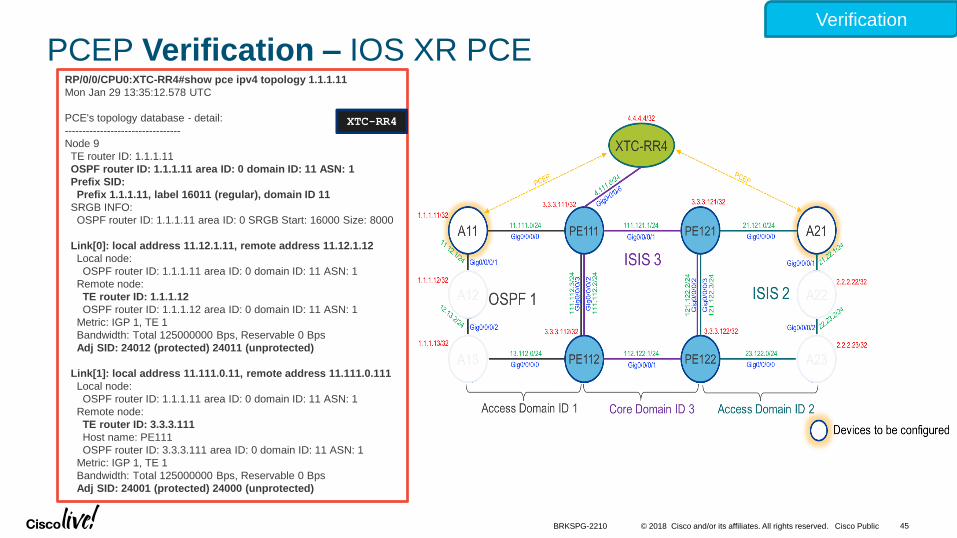
PCEP Verification – IOS XR PCE
Verifying PCEP session
on the server ( PCE)
XTC-RR4
Verification

© 2018 Cisco and/or its affiliates. All rights reserved. Cisco Public
RP/0/0/CPU0:XTC-RR4#show pce ipv4 topology summary
Mon Jan 29 13:30:30.987 UTC
PCE's topology database summary:
--------------------------------
Topology nodes: 11
Prefixes: 14
Prefix SIDs:
Total: 14
Regular: 14
Strict: 0
Links:
Total: 29
EPE: 0
Adjacency SIDs:
Total: 58
Unprotected: 29
Protected: 29
EPE: 0
Private Information:
Lookup Nodes 15
Consistent yes
Update Stats (from IGP and/or BGP):
Noded added: 15
Noded deleted: 0
Links added: 30
Links deleted: 0
Prefix added: 49
Prefix deleted: 0
44BRKSPG-2210
PCEP Verification – IOS XR PCE
PCE Topology Information:
Nodes = 11
Prefix SID = 14
Links = 29
Adjancey SIDs = 58
XTC-RR4
Verification
© 2018 Cisco and/or its affiliates. All rights reserved. Cisco Public
RP/0/0/CPU0:XTC-RR4#show pce ipv4 topology 1.1.1.11
Mon Jan 29 13:35:12.578 UTC
PCE's topology database - detail:
---------------------------------
Node 9
TE router ID: 1.1.1.11
OSPF router ID: 1.1.1.11 area ID: 0 domain ID: 11 ASN: 1
Prefix SID:
Prefix 1.1.1.11, label 16011 (regular), domain ID 11
SRGB INFO:
OSPF router ID: 1.1.1.11 area ID: 0 SRGB Start: 16000 Size: 8000
Link[0]: local address 11.12.1.11, remote address 11.12.1.12
Local node:
OSPF router ID: 1.1.1.11 area ID: 0 domain ID: 11 ASN: 1
Remote node:
TE router ID: 1.1.1.12
OSPF router ID: 1.1.1.12 area ID: 0 domain ID: 11 ASN: 1
Metric: IGP 1, TE 1
Bandwidth: Total 125000000 Bps, Reservable 0 Bps
Adj SID: 24012 (protected) 24011 (unprotected)
Link[1]: local address 11.111.0.11, remote address 11.111.0.111
Local node:
OSPF router ID: 1.1.1.11 area ID: 0 domain ID: 11 ASN: 1
Remote node:
TE router ID: 3.3.3.111
Host name: PE111
OSPF router ID: 3.3.3.111 area ID: 0 domain ID: 11 ASN: 1
Metric: IGP 1, TE 1
Bandwidth: Total 125000000 Bps, Reservable 0 Bps
Adj SID: 24001 (protected) 24000 (unprotected)
45BRKSPG-2210
PCEP Verification – IOS XR PCE
XTC-RR4
Verification

Next Step:Service Enablement or Service Provisioning

© 2018 Cisco and/or its affiliates. All rights reserved. Cisco Public
Network Services Orchestrator (NSO)
• Multi-vendor service orchestrator o Distributed service configuration management
o Transaction integrity
o Validation and rollback
• Single pane of glass for:o L2-L7 networking
o Hardware Devices
o Virtual Appliances
• YANG Model Driven Orchestrationo Service Data models
o Device Data Model
o Network Element Driver
• Highly Scalable for large infrastructure
o One of the existing deployment is managing 60K devices on the network
47BRKSPG-2210
Network Element Drivers
Device Manager
Service Manager
Network Services Orchestrator (NSO) Service
Models
Device
Models
Network-wide CLI, Web UIREST, Java, NETCONF
Network
Engineer
Management
Applications
End-to-End
Transactions
NETCONF, CLI, SNMP, REST, etc.
• Applications
• Controllers

© 2018 Cisco and/or its affiliates. All rights reserved. Cisco Public
Step 1: L3VPN Provisioning
• Configure L3VPN Service on Node A11 and A21
48
Configure
RP/0/0/CPU0:A11#config t
vrf epn
address-family ipv4 unicast
import route-target
1:1
!
export route-target
1:1
!
interface Loopback10
vrf epn
ipv4 address 9.9.9.11 255.255.255.255
!
interface Loopback11
vrf epn
ipv4 address 8.8.8.11 255.255.255.255
!
router bgp 1
bgp router-id 1.1.1.11
address-family ipv4 unicast
!
address-family vpnv4 unicast
!
neighbor 4.4.4.4
remote-as 1
update-source Loopback0
address-family vpnv4 unicast
!
vrf epn
rd 11:11
address-family ipv4 unicast
redistribute connected
PE111 PE121A11 A21
XTC-
RR
ISIS
PE112 PE122A13 A23
A12 A22OSPF ISIS
NSO
A11

© 2018 Cisco and/or its affiliates. All rights reserved. Cisco Public
Step 2: XTC Configuration – L3VPN Route Reflector
• Note that XTC-RR4 is also acting like BGP VPNv4 Route-Reflector
49
Enable PCE
Configure
RP/0/0/CPU0: XTC-RR4#config t
router bgp 1
address-family vpnv4 unicast
!
neighbor-group epn-vpnv4
remote-as 1
update-source Loopback0
address-family vpnv4 unicast
route-reflector-client
!
!
neighbor 1.1.1.11
use neighbor-group epn-vpnv4
!
neighbor 2.2.2.21
use neighbor-group epn-vpnv4
!
commit
PE111 PE121A11 A21
XTC-
RR
ISIS
PE112 PE122A13 A23
A12 A22OSPF ISIS
NSO
VPNv4VPNv4
XTC-RR4
BRKSPG-2210

© 2018 Cisco and/or its affiliates. All rights reserved. Cisco Public
RP/0/0/CPU0:XTC-RR4#sh bgp vpnv4 unicast summary
Mon Mar 6 18:39:44.111 UTC
BGP router identifier 4.4.4.4, local AS number 1
BGP generic scan interval 60 secs
Non-stop routing is enabled
BGP table state: Active
Table ID: 0x0 RD version: 0
BGP main routing table version 5
BGP NSR Initial initsync version 1 (Reached)
BGP NSR/ISSU Sync-Group versions 0/0
BGP scan interval 60 secs
BGP is operating in STANDALONE mode.
Process RcvTblVer bRIB/RIB LabelVer ImportVer SendTbl
Ver StandbyVer
Speaker 5 5 5 5 5 0
Neighbor Spk AS MsgRcvd MsgSent TblVer InQ
OutQ Up/Down St/PfxRcd
1.1.1.11 0 1 7 9 5 0 0 00:03:19 2
2.2.2.21 0 1 7 8 5 0 0 00:03:39 2
50BRKSPG-2210
BGP VPNv4 Session Verification
Verification
PE111 PE121A11 A21
XTC-
RR
ISIS
PE112 PE122A13 A23
A12 A22OSPF ISIS
NSO
VPNv4VPNv4
XTC-RR4

© 2018 Cisco and/or its affiliates. All rights reserved. Cisco Public
RP/0/0/CPU0:A11#show bgp vpnv4 unicast
Mon Mar 6 18:42:41.895 UTC
BGP router identifier 1.1.1.11, local AS number 1
BGP generic scan interval 60 secs
Non-stop routing is enabled
BGP table state: Active
Table ID: 0x0 RD version: 0
BGP main routing table version 8
BGP NSR Initial initsync version 7 (Reached)
BGP NSR/ISSU Sync-Group versions 0/0
BGP scan interval 60 secs
Status codes: s suppressed, d damped, h history, * valid, > best
i - internal, r RIB-failure, S stale, N Nexthop-discard
Origin codes: i - IGP, e - EGP, ? - incomplete
Network Next Hop Metric LocPrf Weight Path
Route Distinguisher: 11:11 (default for vrf epn)
*> 8.8.8.11/32 0.0.0.0 0 32768 ?
*> 9.9.9.11/32 0.0.0.0 0 32768 ?
Route Distinguisher: 21:21
* i8.8.8.21/32 2.2.2.21 0 100 0 ?
* i9.9.9.21/32 2.2.2.21 0 100 0 ?
51BRKSPG-2210
BGP VPNv4 Session Verification
Remote Prefix Routes
8.8.8.21/32
9.9.9.21/32
Verfication
A11

© 2018 Cisco and/or its affiliates. All rights reserved. Cisco Public
extcommunity-set opaque BLUE
10
end-set
!
extcommunity-set opaque GREEN
20
end-set
!
route-policy SET_COLOR
if destination in (8.8.8.0 0.0.0.255 ) then
set extcommunity color BLUE
else
set extcommunity color GREEN
endif
end-policy
52BRKSPG-2210
Step 3: Configure Route Policy on A11 and A21
If Prefix 8.8.8.0/24 then color=10
If Prefix = Any thing else then color =20
Configure
A11

© 2018 Cisco and/or its affiliates. All rights reserved. Cisco Public
router bgp 1
bgp router-id 1.1.1.11
!
address-family vpnv4 unicast
!
neighbor 4.4.4.4
remote-as 1
update-source Loopback0
address-family vpnv4 unicast
route-policy SET_COLOR out
53BRKSPG-2210
Step 4: Apply the route-policy to the BGP VPNv4 unicast peering between A11 and the route reflector (XTC-RR4)
Egress PE Policy
If Prefix 8.8.8.0/24 then set Color 10
else
Set Color 20
Configure
A11

© 2018 Cisco and/or its affiliates. All rights reserved. Cisco Public
RP/0/0/CPU0:A11#config t
router ospf 1
area 0
mpls traffic-eng
!
mpls traffic-eng router-id Loopback0
!
ipv4 unnumbered mpls traffic-eng Loopback0
!
mpls traffic-eng
commit
54BRKSPG-2210
Step 5: Enable Traffic Engineering on A11 and A12
Enable Traffic Engineering Under
IGP
Configure
A11

© 2018 Cisco and/or its affiliates. All rights reserved. Cisco Public
L3VPN Service ValidationControl Plane
RP/0/0/CPU0:A11# show bgp vrf epn
Mon Jan 29 15:11:52.273 UTC
BGP VRF epn, state: Active
BGP Route Distinguisher: 11:11
VRF ID: 0x60000001
BGP router identifier 1.1.1.11, local AS number 1
Non-stop routing is enabled
BGP table state: Active
Table ID: 0xe0000010 RD version: 61
BGP main routing table version 62
BGP NSR Initial initsync version 13 (Reached)
BGP NSR/ISSU Sync-Group versions 0/0
Status codes: s suppressed, d damped, h history, * valid, > best
i - internal, r RIB-failure, S stale, N Nexthop-discard
Origin codes: i - IGP, e - EGP, ? - incomplete
Network Next Hop Metric LocPrf Weight Path
Route Distinguisher: 11:11 (default for vrf epn)
*> 8.8.8.11/32 0.0.0.0 0 32768 ?
*>i8.8.8.21/32 2.2.2.21 C:10 0 100 0 ?
*> 9.9.9.11/32 0.0.0.0 0 32768 ?
*>i9.9.9.21/32 2.2.2.21 C:20 0 100 0 ?
Processed 4 prefixes, 4 paths
RP/0/0/CPU0:A11#sh bgp vpnv4 unicast vrf epn 8.8.8.21/32
Mon Jan 29 15:14:35.342 UTC
BGP routing table entry for 8.8.8.21/32, Route Distinguisher: 11:11
Versions:
Process bRIB/RIB SendTblVer
Speaker 57 57
Last Modified: Jan 27 05:41:18.359 for 2d09h
Paths: (1 available, best #1)
Not advertised to any peer
Path #1: Received by speaker 0
Not advertised to any peer
Local
2.2.2.21 C:10 (bsid:24018) from 4.4.4.4 (2.2.2.21)
Received Label 24007
Origin incomplete, metric 0, localpref 100, valid, internal, best, group-
best, import-candidate, imported
Received Path ID 0, Local Path ID 0, version 55
Extended community: Color:10 RT:1:1
Originator: 2.2.2.21, Cluster list: 4.4.4.4
SR ODN policy color 10, up, registered, bsid 24018, if-handle
0x00000190
Source AFI: VPNv4 Unicast, Source VRF: default, Source Route
Distinguisher: 21:21
Control PlaneA11A11
SR Policy Color
L3VPN Verfication
Color
BRKSPG-2210 55

© 2018 Cisco and/or its affiliates. All rights reserved. Cisco Public
L3VPN Service ValidationForwarding Plane
RP/0/0/CPU0:A11#sh segment-routing traffic-eng policy
Mon Jan 29 15:16:29.444 UTC
SR-TE policy database
---------------------
Name: bgp_AP_1 (Color: 20, End-point: 2.2.2.21)
Status:
Admin: up Operational: up for 1d22h (since Jan 27 16:40:54.734)
Candidate-paths:
Preference 100:
Dynamic (pce 4.4.4.4) (active)
Weight: 0, Metric Type: IGP
16111 [Prefix-SID, 3.3.3.111]
16121 [Prefix-SID, 3.3.3.121]
16021 [Prefix-SID, 2.2.2.21]
Attributes:
Binding SID: 24013
Allocation mode: dynamic
State: Programmed
Policy selected: yes
Forward Class: 0
Distinguisher: 0
Auto-policy info:
Creator: BGP
IPv6 caps enable: no
RP/0/0/CPU0:A11#sh segment-routing traffic-eng policy
Mon Jan 29 15:16:29.444 UTC
SR-TE policy database
---------------------
Name: bgp_AP_8 (Color: 10, End-point: 2.2.2.21)
Status:
Admin: up Operational: up for 2d09h (since Jan 27 05:41:18.356)
Candidate-paths:
Preference 100:
Dynamic (pce 4.4.4.4) (active)
Weight: 0, Metric Type: TE
16112 [Prefix-SID, 3.3.3.112]
16122 [Prefix-SID, 3.3.3.122]
24006 [Adjacency-SID, 121.122.2.122 - 121.122.2.121]
16021 [Prefix-SID, 2.2.2.21]
Attributes:
Binding SID: 24018
Allocation mode: dynamic
State: Programmed
Policy selected: yes
Forward Class: 0
Distinguisher: 0
Auto-policy info:
Creator: BGP
IPv6 caps enable: no
Forwarding PlaneA11A11
IGP Path
Verification
Policy Color
and End Point
TE Path
Policy Color
and End Point
BRKSPG-2210 56

© 2018 Cisco and/or its affiliates. All rights reserved. Cisco Public
Access Domain ID 2
Data Plane (IGP Metric)
PE111 PE121A11 A21
XTC-RR4
ISIS 2
PE112 PE122A13 A23
A12 A22
OSPF 1 ISIS 3
Gig0/0/0/0
Access Domain ID 1 Core Domain ID 3
11.111.0/24 111.121.1/24
111.1
12.3
/24
112.122.1/24
121.1
22.2
/24
23.122.0/24
21.121.0/24
13.112.0/24111.1
12.2
/24
121.1
22.3
/24
4.4.4.4/32
3.3.3.111/32 3.3.3.121/32
3.3.3.112/32 3.3.3.122/32
1.1.1.11/32
1.1.1.12/32
1.1.1.13/32
2.2.2.21/32
2.2.2.22/32
2.2.2.23/32
Gig0/0/0/0
Gig0/0/0/1
Gig0/0/0/2
Gig0/0/0/0
Gig0/0/0/0
Gig
0/0
/0/3
Gig
0/0
/0/2
Gig
0/0
/0/2
Gig
0/0
/0/3
Gig0/0/0/1
Gig0/0/0/2
Gig0/0/0/1
Gig0/0/0/1
frame
service
16021
16121
16111
frame
service
16021 frame
frame
service
Prefix-SID-List [16111,16121,16021]
PHP
BRKSPG-2210 57
NSO

© 2018 Cisco and/or its affiliates. All rights reserved. Cisco Public
NSO
PE111 PE121A11 A21
XTC-RR4
ISIS 2
PE112 PE122A13 A23
A12 A22
OSPF 1 ISIS 3
Gig0/0/0/0
11.111.0/24 111.121.1/24
111.1
12.3
/24
112.122.1/24
121.1
22.2
/24
23.122.0/24
21.121.0/24
13.112.0/24
111.1
12.2
/24
121.1
22.3
/24
4.4.4.4/32
3.3.3.111/32 3.3.3.121/32
1.1.1.11/32
1.1.1.12/32
1.1.1.13/32
2.2.2.21/32
2.2.2.22/32
2.2.2.23/32
Gig0/0/0/0
Gig0/0/0/1
Gig0/0/0/2
Gig0/0/0/0
Gig0/0/0/0
Gig
0/0
/0/3
Gig
0/0
/0/2
Gig
0/0
/0/2
Gig
0/0
/0/3
Gig0/0/0/1
Gig0/0/0/2
Gig0/0/0/1
Gig0/0/0/1
TE Metric 100
TE
Metr
ic 1
00
3.3.3.112/32 3.3.3.122/32
frame
service
16021
16122
16112
Adj-SID
frame
service
16021
16122
Adj-SID
frame
service
16021
Adj-SID
Data Plane (TE Metric)
frame
service
16021
frame
service
frameframe
service
16021
16122
Adj-SID
16112
BRKSPG-2210 58

© 2018 Cisco and/or its affiliates. All rights reserved. Cisco Public
L3VPN Service ValidationForwarding Plane
RP/0/0/CPU0:A11#sh cef vrf epn 8.8.8.21/32
Mon Jan 29 15:18:16.686 UTC
8.8.8.21/32, version 38, internal 0x5000001 0x0 (ptr 0xa134e4a4) [1],
0x0 (0x0), 0x208 (0xa15d54d8)
Updated Jan 27 05:41:18.405
Prefix Len 32, traffic index 0, precedence n/a, priority 3
via local-label 24018, 3 dependencies, recursive [flags 0x6000]
path-idx 0 NHID 0x0 [0xa163e96c 0x0]
recursion-via-label
next hop VRF - 'default', table - 0xe0000000
next hop via 24018/0/21
next hop bgp_AP_8 labels imposed {ImplNull 24007}
!
RP/0/0/CPU0:A11#traceroute 8.8.8.21 source 8.8.8.11 vrf epn
Type escape sequence to abort.
Tracing the route to 8.8.8.21
1 11.111.0.111 [MPLS: Labels 16112/16122/24006/16021/24007 Exp
0] 29 msec 19 msec 19 msec
2 111.112.2.112 [MPLS: Labels 16122/24006/16021/24007 Exp 0] 29
msec 19 msec 19 msec
3 112.122.1.122 [MPLS: Labels 24006/16021/24007 Exp 0] 29
msec 29 msec 19 msec
4 121.122.2.121 [MPLS: Labels 16021/24007 Exp 0] 19 msec 19
msec 19 msec
5 21.121.0.21 29 msec * 29 msec
RP/0/0/CPU0:XTC-RR4#show pce lsp detail
Mon Jan 29 15:20:36.485 UTC
PCE's tunnel database:
----------------------
PCC 1.1.1.11:
Tunnel Name: bgp_AP_1
LSPs:
LSP[0]:
source 1.1.1.11, destination 2.2.2.21, tunnel ID 1, LSP ID 84
State: Admin up, Operation active
Setup type: Segment Routing
Binding SID: 24013
Bandwidth: signaled 0, applied 0
! [Output Trimmed]
Reported path:
Metric type: IGP, Accumulated Metric 0
SID[0]: Node, Label 16111, Address 3.3.3.111
SID[1]: Node, Label 16121, Address 3.3.3.121
SID[2]: Node, Label 16021, Address 2.2.2.21
Computed path: (Local PCE)
Computed Time: Mon Jan 29 15:10:39 2018 (00:09:57 ago)
Metric type: IGP, Accumulated Metric 21
SID[0]: Node, Label 16111, Address 3.3.3.111
SID[1]: Node, Label 16121, Address 3.3.3.121
SID[2]: Node, Label 16021, Address 2.2.2.21
!
[SNIP]
Forwarding Plane
XTC-RR4A11
Primary Path &
Label Imposed
Computed Path
Verification
TE Path
Reported Path
SR Policy Status

Summary

© 2018 Cisco and/or its affiliates. All rights reserved. Cisco Public
VPN acme
Site 1
VPN acme
Site 2
Routing defined path
Resource constraint path
PE111 PE121A11 A21
XTC-RR
ISIS
PE112 PE122A13 A23
A12 A22OSPF ISIS
NSO
• Multi-domain Segment Routing (SR-TE) policies computed by a stateful SR PCE
• Coupled with SR On-Demand Next-hops (ODN)
• Scalable – automatic SR-TE policies triggered by service (VPN) routes
• Auto-Steering – automatic steering of service traffic into SR-TE policies
BRKSPG-2210 61

© 2018 Cisco and/or its affiliates. All rights reserved. Cisco Public
Summary BGP-LS for Topology Discovery
PE111 PE121A11 A21
XTC-RR
ISIS
PE112 PE122A13 A23
A12 A22OSPF ISIS
NSO
BGP-LSBGP-LS
BGP-LSBGP-LS
BRKSPG-2210 62

© 2018 Cisco and/or its affiliates. All rights reserved. Cisco Public
Summary PCEP Session between PCE and PCC
A2x as SR PCC
PCEP PCEP
XTC-RR as SR PCE
A1x as SR PCC
PE111 PE121A11 A21
XTC-RR
ISIS
PE112 PE122A13 A23
A12 A22OSPF ISIS
NSO
BRKSPG-2210 63

© 2018 Cisco and/or its affiliates. All rights reserved. Cisco Public
SummaryStep 1 – NSO Instantiate the L3VPN Service
1• NSO instantiates an L3 VPN service on PEs
• Note: NO transport elements configured by NSO
VPN acme
Site 1
VPN acme
Site 2
NSO
PE111 PE121A11 A21
ISIS
PE112 PE122A13 A23
A12 A22OSPF ISIS
A11 A21
BRKSPG-2210 64

© 2018 Cisco and/or its affiliates. All rights reserved. Cisco Public
SummaryStep 2 - VPN routes propagated via BGP
PE111 PE121A11 A21
ISIS
PE112 PE122A13 A23
A12 A22OSPF ISIS
VPN acme
Site 1
VPN acme
Site 2
XTC-
RR
XTC-RR as BGP RR
A11 A21
BRKSPG-2210 65

© 2018 Cisco and/or its affiliates. All rights reserved. Cisco Public
SummaryStep 2 - VPN routes propagated via BGP
PE111 PE121A11 A21
ISIS
PE112 PE122A13 A23
A12 A22OSPF ISIS
2
VPN acme
Site 1
VPN acme
Site 2
XTC-
RR
XTC-RR as BGP RR
A11 A21
BRKSPG-2210 66

© 2018 Cisco and/or its affiliates. All rights reserved. Cisco Public
SummaryStep 2 - VPN routes propagated via BGP
PE111 PE121A11 A21
ISIS
PE112 PE122A13 A23
A12 A22OSPF ISIS
2
VPN acme
Site 1
VPN acme
Site 2
XTC-
RR BGP VPNv4BGP VPNv4
• Routes tagged with user-defined community to convey SLA requirements
• VPN routes propagated via BGP
XTC-RR as BGP RR
A11 A21
BRKSPG-2210 67

© 2018 Cisco and/or its affiliates. All rights reserved. Cisco Public
SummaryStep 3 - PCE Path Computation - Request
PE111 PE121
ISIS
PE112 PE122A13 A23
A12 A22
OSPF
ISIS
VPN acme
Site 1
VPN acme
Site 2
XTC-
RRXTC-RR as SR PCE
A11 as SR PCC
A11 A21
BRKSPG-2210 68

© 2018 Cisco and/or its affiliates. All rights reserved. Cisco Public
SummaryStep 3 - PCE Path Computation - Request
PE111 PE121
ISIS
PE112 PE122A13 A23
A12 A22
OSPF
ISIS
VPN acme
Site 1
VPN acme
Site 2
XTC-
RRXTC-RR as SR PCE
3• Ingress PE matches on user-specified BGP community
• Ingress PE enforces policy associated with the community
A11 as SR PCC
A11 A21
BRKSPG-2210 69

© 2018 Cisco and/or its affiliates. All rights reserved. Cisco Public
SummaryStep 3 - PCE Path Computation - Request
PE111 PE121
ISIS
PE112 PE122A13 A23
A12 A22
OSPF
ISIS
VPN acme
Site 1
VPN acme
Site 2
XTC-
RRXTC-RR as SR PCE
3• Ingress PE matches on user-specified BGP community
• Ingress PE enforces policy associated with the community
PCEP
Need a path to node (A21)
Rule: Minimize TE metric
<policy_sample>
IF color = 10
THEN
contact PCE
request path to BGP NH
minimize TE metric
A11 as SR PCC
A11 A21
BRKSPG-2210 70

© 2018 Cisco and/or its affiliates. All rights reserved. Cisco Public
SummaryStep 4 - PCE Path Computation - Response
PE111 PE121
ISIS
PE112 PE122A13 A23
A12 A22OSPF ISIS
VPN acme
Site 1
VPN acme
Site 2
XTC-
RRXTC-RR as SR PCE
PCEPSR-EROs
Label 1
Label 2
Label 3
4• PCE computes path
• PCE replies to PCC with SR-EROs (segment (SID) list)A11 as SR PCC
A11 A21
BRKSPG-2210 71

© 2018 Cisco and/or its affiliates. All rights reserved. Cisco Public
SummaryStep 5 - Service Up and Running with the path established.
PE111 PE121
ISIS
PE112 PE122A13 A23
A12 A22OSPF ISIS
VPN acme
Site 1
VPN acme
Site 2
FIB
Y/24 via label 24018
A11 A21
BRKSPG-2210 72

© 2018 Cisco and/or its affiliates. All rights reserved. Cisco Public
SummaryStep 5 - Service Up and Running with the path established.
PE111 PE121
ISIS
PE112 PE122A13 A23
A12 A22OSPF ISIS
VPN acme
Site 1
VPN acme
Site 2
5• PE programs SR-TE policy in FIB
• PE allocates a Binding-SID (B-SID) to it
• PE programs forwarding for VPN route via B-SID of SR-TE policy
B-SID = 24018
FIB
Y/24 via label 24018
A11 A21
BRKSPG-2210 73

© 2018 Cisco and/or its affiliates. All rights reserved. Cisco Public
SummaryStep 5 - Service Up and Running with the path established.
PE111 PE121
ISIS
PE112 PE122A13 A23
A12 A22OSPF ISIS
VPN acme
Site 1
VPN acme
Site 2
B-SID = 24018
FIB
Y/24 via label 24018
A11 A21
BRKSPG-2210 74
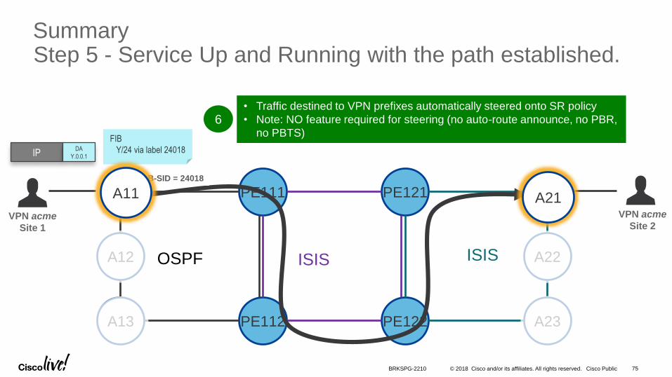
© 2018 Cisco and/or its affiliates. All rights reserved. Cisco Public
6• Traffic destined to VPN prefixes automatically steered onto SR policy
• Note: NO feature required for steering (no auto-route announce, no PBR,
no PBTS)
SummaryStep 5 - Service Up and Running with the path established.
PE111 PE121
ISIS
PE112 PE122A13 A23
A12 A22OSPF ISIS
VPN acme
Site 1
VPN acme
Site 2
B-SID = 24018
IPDA
Y.0.0.1
FIB
Y/24 via label 24018
A11 A21
BRKSPG-2210 75

Conclusions

© 2018 Cisco and/or its affiliates. All rights reserved. Cisco Public
Summary
• Automation
• Configuration through Netconf/Yang Models
• Network Simplification with Segment Routing
• Enable Topology Discovery
• Enable inter Domains Traffic Engineering
77BRKSPG-2210BRKSPG-2210
Core
Access Domain B
Access Domain C
Programmatic Approach
1- Automate the network setup
3- Simplify MPLS transport with Segment routing
4- Turn on BGP-LS
5- Turn on PCEP
2- Use of Netconf/Yang
Controllers, Orchestrators

© 2018 Cisco and/or its affiliates. All rights reserved. Cisco Public
References
• LTRMPL-2104 - Cisco WAN Automation Engine (WAE) Network Programmability with Segment Routing
• Agile Carrier Ethernet Demonstration on Youtube -https://www.youtube.com/watch?v=biYqyAn9rl0
• Segment Routing .net - http://www.segment-routing.net/
• Segment Routing Demo Friday - https://www.sdxcentral.com/resources/sdn-demofriday/segment-routing-cisco-demofriday/
• Cisco Programmability Yang blog - http://blogs.cisco.com/tag/yang
• Tail-f netconf yang tutorials - http://www.tail-f.com/education/
• BGP-LS linkedin blog: https://www.linkedin.com/pulse/introduction-open-api-bgp-link-state-bgp-ls-source-controller-abeer?trk=prof-post
• Netconf linkedin blog: https://www.linkedin.com/pulse/netconf-rfc-6242-protocol-tutorial-ahmed-n-abeer?trk=prof-post
78BRKSPG-2210

© 2018 Cisco and/or its affiliates. All rights reserved. Cisco Public
Cisco Spark
Questions? Use Cisco Spark to communicate with the speaker after the session
1. Find this session in the Cisco Live Mobile App
2. Click “Join the Discussion”
3. Install Spark or go directly to the space
4. Enter messages/questions in the space
How
cs.co/ciscolivebot#BRKSPG-2210

© 2018 Cisco and/or its affiliates. All rights reserved. Cisco Public
• Please complete your Online Session Evaluations after each session
• Complete 4 Session Evaluations & the Overall Conference Evaluation (available from Thursday) to receive your Cisco Live T-shirt
• All surveys can be completed via the Cisco Live Mobile App or the Communication Stations
Don’t forget: Cisco Live sessions will be available for viewing on-demand after the event at www.ciscolive.com/global/on-demand-library/.
Complete Your Online Session Evaluation

© 2018 Cisco and/or its affiliates. All rights reserved. Cisco Public
Continue Your Education
• Demos in the Cisco campus
• Walk-in Self-Paced Labs
• Tech Circle
• Meet the Engineer 1:1 meetings
• Related sessions
81BRKSPG-2210

Thank you
