nonlinear modeling as a metrology tool to characterize
TRANSCRIPT

V.A. Khokhlova,1,2 P.V. Yuldashev,2 W. Kreider,1
O.A. Sapozhnikov,1,2 M.R. Bailey,2 and L.A. Crum2
Nonlinear modeling as a metrology tool to characterize
high intensity focused ultrasound fields
2Department of AcousticsPhysics Faculty
Moscow State UniversityRussia
1Center for Industrial and Medical Ultrasound
Applied Physics LaboratoryUniversity of Washington
164th Meeting of the Acoustical Society of America, Kansas City, MO, 22 - 26 October 2012
• Introduction High Intensity Focused Ultrasound fields = nonlinear fields
• Metrology of nonlinear HIFU fieldscombined measurement and modeling approach,calibration in water, translation (derating) to tissue, enhancement of heating, predicting bioeffects
• HIFU treatment protocols based on nonlinear effectscontrolled mechanical and thermal bioeffects in the presence of shock
• Conclusions
Outline
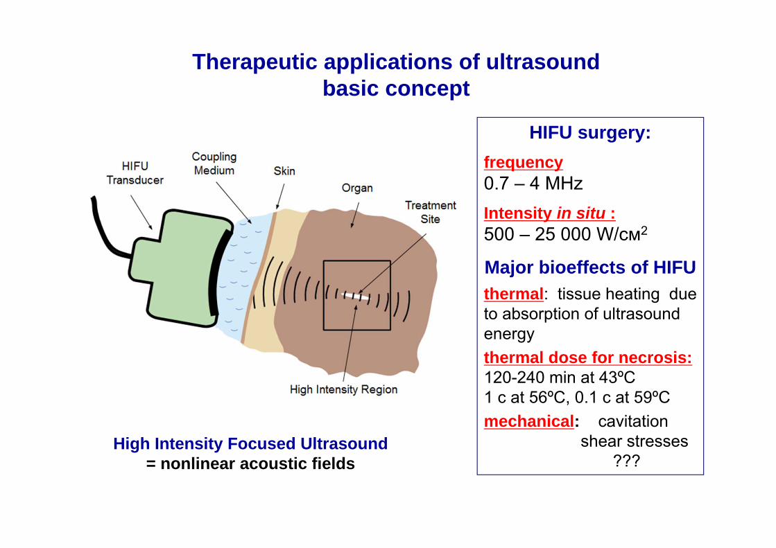
Therapeutic applications of ultrasoundbasic concept
HIFU surgery:frequency0.7 – 4 MHzIntensity in situ :500 – 25 000 W/cм2
Major bioeffects of HIFUthermal: tissue heating due to absorption of ultrasound energythermal dose for necrosis:120-240 min at 43ºC1 c at 56ºC, 0.1 c at 59ºCmechanical: cavitation
shear stresses???
High Intensity Focused Ultrasound= nonlinear acoustic fields
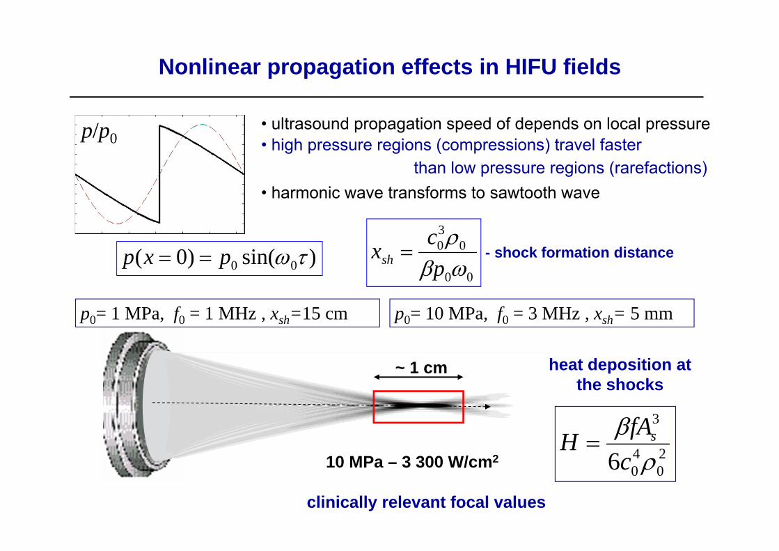
Nonlinear propagation effects in HIFU fields
• ultrasound propagation speed of depends on local pressure• high pressure regions (compressions) travel faster
than low pressure regions (rarefactions)• harmonic wave transforms to sawtooth wave
)sin()0( 00 pxp 00
030
pcxsh - shock formation distance
p/p0
p0= 1 MPa, f0 = 1 MHz , xsh=15 cm p0= 10 MPa, f0 = 3 MHz , xsh= 5 mm
20
40
3
6 cfAH s
heat deposition at the shocks
~ 1 cm
10 MPa – 3 300 W/cm2
clinically relevant focal values

Nonlinear acoustics• peak positive and negative pressures (p+ ; p-)• shock amplitude (As)• narrower focal zone, enhanced heat deposition
HIFU fields in the presence of nonlinear effects:acoustic characterization and new bioeffects
Linear acoustics• focal pressure amplitude (pF)• broader focal zone
pF
5 mm
5 mm
5 mm
Different effects in tissue:thermal coagulation
boilingemulsificationshear stresses
immune response
Nonlinear effects and resulting shocks are important in HIFU metrologyas they result in enhanced heating and additional nonthermal bioeffects
p p
p
sA

Nonlinear modeling combined with measurements can be an effective tool to characterize outputs of HIFU transducers
calibration of HIFU fields in water
derating nonlinear water measurements to tissueestimating therapeutic dose delivered
developing treatment protocols
making HIFU more efficient and safe
optimizing treatment avoiding or using nonlinear effectsstudying new bioeffects

Characterization of HIFU fields in water: combined measurement and modeling approach
2D clinical phased array
1.2 MHz operational frequency128 mm diameter, 120 mm focus256 elements of 6.6 mm diameter each central hole for imaging
MR-guided HIFU system(Sonalleve 3.0T, Philips Healthcare)
examples: typical HIFU sources of different geometry
single element HIFU transducer
2.158 MHz operational frequency45 mm diameter, 45 mm focus
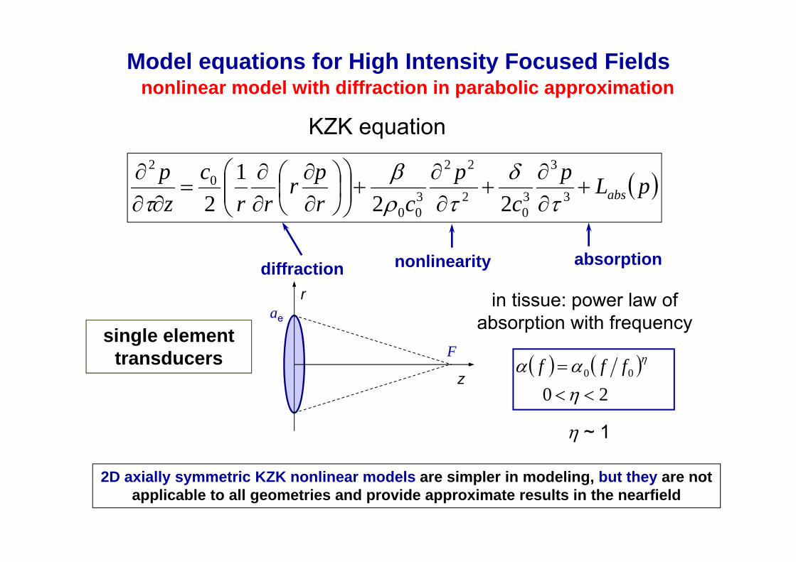
Model equations for High Intensity Focused Fields
KZK equation
nonlinearity absorptiondiffraction
nonlinear model with diffraction in parabolic approximation
pLpc
pcr
prrr
czp
abs
3
3
30
2
22
300
02
221
2
single elementtransducers
z
F
rae
2D axially symmetric KZK nonlinear models are simpler in modeling, but they are not applicable to all geometries and provide approximate results in the nearfield
20
00
fff
in tissue: power law of absorption with frequency
~ 1
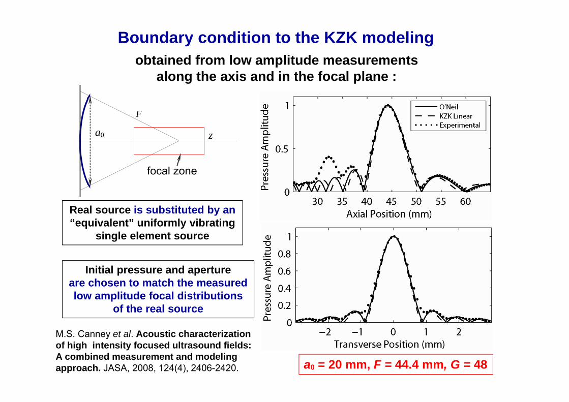
Boundary condition to the KZK modeling
Initial pressure and apertureare chosen to match the measured low amplitude focal distributions
of the real source
a0
F
z
focal zone
a0 = 20 mm, F = 44.4 mm, G = 48
Real source is substituted by an “equivalent” uniformly vibrating
single element source
obtained from low amplitude measurements along the axis and in the focal plane :
M.S. Canney et al. Acoustic characterization of high intensity focused ultrasound fields: A combined measurement and modeling approach. JASA, 2008, 124(4), 2406-2420.

Nonlinear propagation effects and shock formation
in HIFU fieldsf0 = 2 MHz , d0 = F = 44 mm
water , 180 W acoustic powerinput: 7.8 W/cm2 / 4.8 bars at focus: 18 000 W/cm2 / 230 bars
spectrum
f/f0
axial peak pressure positive p+/p0 and negative p-/p0
z/F
one cycle of a HIFU waveform p/p0

0
20
40
60 measured waveform
65.554.543.532.521.5 *10-5
time, s
pressure, MPasource pressure: 0.4 MPa source intensity: 5 W/cm2
linearly estimatedfocal pressure: 18.5 MPafocal intensity: 11 500 W/cm2
FOPH frequency response
Modeling results are more accurate than measurements at high power outputs (due to bandwidth limitations of hydrophones) and can be applied to predict in situ fields
Validation of nonlinear modeling at high outputs in water
focal waveform modeling and measurements with FOPH hydrophones
Hydrophone bandwidth is critical (100 MHz versus 30 MHz) for measuring p+

Model equations for High Intensity Focused Fields
0/ czt
zF
y
x
a0 HIFU arrays
3D full diffraction nonlinear model
3
3
30
2
22
300
2
2
2
2
2
20
2
222
pc
pcz
pyp
xpc
zp
Westervelt equation:
nonlinearity absorptiondiffraction
3D full wave nonlinear models can accurately simulate the entire field of HIFU sources at high outputs, but they are very intensive computationally
P.V. Yuldashev, V.A. Khokhlova. Simulation of three-dimensional nonlinearfields of ultrasound therapeutic arrays.Acoustical Physics, 2011, 57(3), 334–343.

Boundary condition for the modelingobtained from measurements using acoustic holography
hydrophonewater
HIFU transducer
measurement plane
experimental arrangementfor reconstruction of vibration velocity at the surface of the transducer Philips MR-guided HIFU source
O.A. Sapozhnikov et al. Reconstruction of the normal velocity distribution on the surface of an ultrasonic transducer from the acoustic pressure measured on a reference surface. Acoustical Physics, 2003, v.49(3), 354–360.

2D multi element clinical phased arrayPhilips MR-guided HIFU source
W. Kreider et al. Acoustic measurements and holographic reconstruction of the Philips MR-guided HIFU source. 2nd Int. MR-guided Focused Ultrasound Symp 2010, p.79.
Boundary condition to the modelingreconstructed experimentally using acoustic holography
magnitude
phase
Array elements do not vibrate uniformly as ideal pistons
reconstructed 2D velocity distribution at the array surface
Hologram
3D acoustic field
Therapeutic array
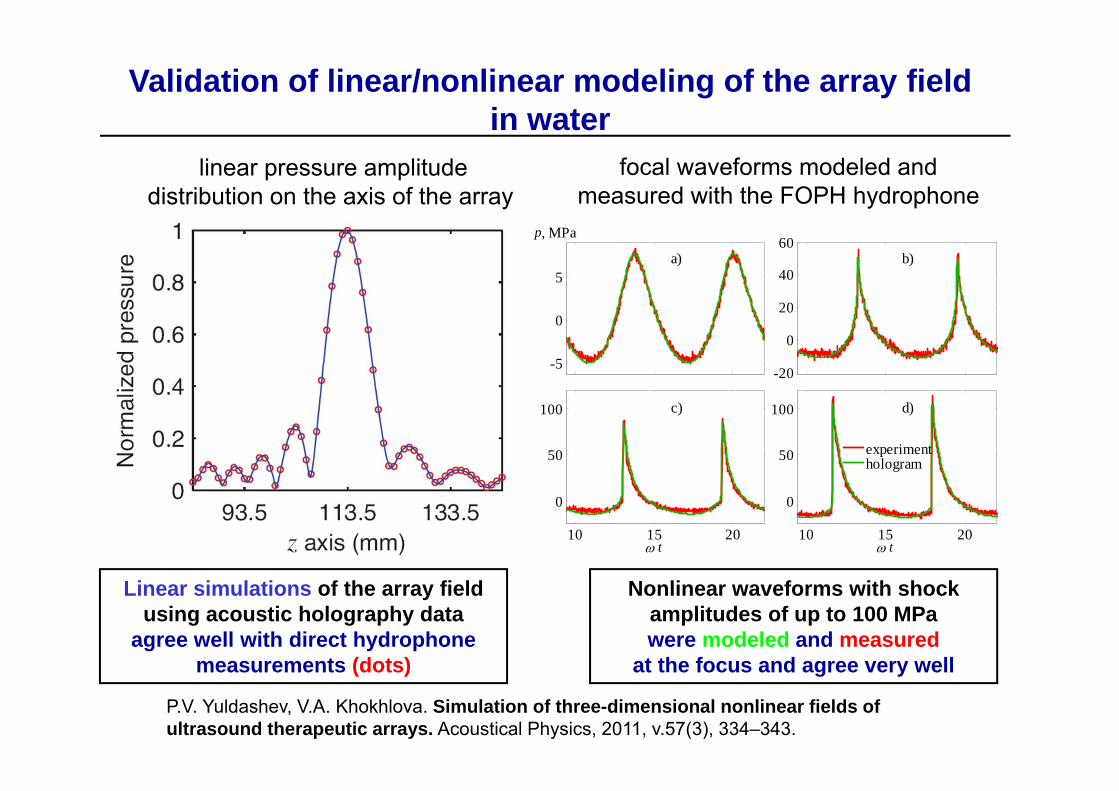
Validation of linear/nonlinear modeling of the array fieldin water
focal waveforms modeled and measured with the FOPH hydrophone
-20
0
20
40
60b)
10 15 20
0
50
100
t
c)
10 15 20
0
50
100
t
d)
-5
0
5
p, MPa
a)
experimenthologram
Linear simulations of the array field using acoustic holography data
agree well with direct hydrophone measurements (dots)
linear pressure amplitude distribution on the axis of the array
Nonlinear waveforms with shock amplitudes of up to 100 MPa were modeled and measured
at the focus and agree very well
P.V. Yuldashev, V.A. Khokhlova. Simulation of three-dimensional nonlinear fields of ultrasound therapeutic arrays. Acoustical Physics, 2011, v.57(3), 334–343.

pF
p0, f0
2r0F
Nonlinear derating method
3000
02
0 pp
FcfrG F
strongly focused transducer
linear focusing gain
On-axis linear propagation curves for pressure amplitude (G = 40)
at the focus:
here L=F, F = 1 (example)
)exp()()( 00 Lwaterptissuep
)()( waterptissuep FF
deration to tissue
– absorption L – focal depth in tissue
at the source:
Equal pressure at the focus = equal pressures in the focal lobe (for high gain sources): nonlinear effects will be very similar in water and in tissue
0.25 0.50 0.75 1.00 1.250
10
20
30
40p/p0 water
tissue
x/F
0.95 1.00 1.0532
36
40
0.25 0.50 0.75 1.00 1.250
10
20
30
40p/p0 water
tissue
x/F
0.95 1.00 1.0532
36
40

Experimental validation of derating method:measurements behind ex vivo bovine liver
f0 = 2 MHzF = 2r0 = 45 mmG = pF / p0 = 48
liver, 27 mm thick
fiber optichydrophone
p0 = 0.29 MPa – waterp0 = 0.48 MPa – liver
measured focal waveform:water versus liver
= 0.7 dB/(cm MHz)p0(tissue) =p0(water)·exp( L)
0.0 0.2 0.4 0.6 0.8 1.0-10
0
10
20
30
40
50 FOPH (Water) FOPH (Liver) KZK (Liver)
time (s)
Pres
sure
(MPa
)
Focal waveforms measured, simulated, and derated from calibration in water agree very well.

Measurement of shock waves in tissue using FOPH
FOPH
Do shocks exist in HIFU fields in inhomogeneous tissue?
Measured shock waveform behind
2.5 cm thickex vivo porcine
body wall
Measured shock waveform behind
2.0 cm thickex vivo liver sample
Shock waves of up to 100 MPa amplitude are clinically relevant

intensity max 16 000 W/cm2
heat deposition max 56 000 W/cm3
peak negative pressure max 113 bars
boiling cavitation
In situ nonlinear field Gel phantom 7% BSA
peak positive pressure max 630 bars
0.0 0.2 0.4 0.6 0.80.5
1.0
1.5
2.0
2.5
3.0
3.5
experiment
maximum localizationmaximum asymmetry of the waveform
N
K(P+)
Nonlinear heating is much more localized than cavitation, heating due to shocks results in ms boiling. Time to boil agrees better with the modeling
Example

different peak amplitude and duty cycle = same average HIFU power
advantages of pulsing schemes with high peak pressures:
- enhanced heating by shocks- mechanical effect- time windows for imaging- visualization of bubbles
Shock waves, ms boiling, and pulsing schemes and in HIFU
lesions of different types
5 mm 5 mm
5 mm
As
nonlinear shock wave

Nonlinear acoustic effects are clinically relevant and critical in some current applications of HIFU
Nonlinear HIFU fields can be accurately characterized using a combined modeling and measurement approach
Newer bioeffects can be induced in tissue using strongly distorted nonlinear waves with shocks
Conclusions
AcknowledgementsWork supported by:
NIH EB007643