nxair h catalogd...circuit-breaker switchgear type nxair h siemens india - 1 5 technical data room...
TRANSCRIPT
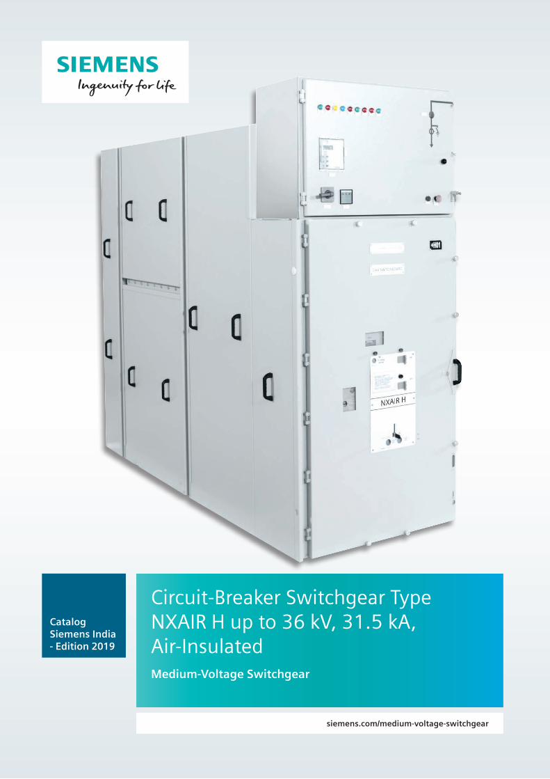
Circuit-Breaker Switchgear Type NXAIR H up to 36 kV, 31.5 kA, Air-InsulatedMedium-Voltage Switchgear
siemens.com/medium-voltage-switchgear
Catalog Siemens India - Edition 2019
Contents
Circuit-BreakerSwitchgearType NXAIR H up to 36 kV, 31.5 kA,Air-Insulated
Medium-Voltage Switchgear
Catalog Siemens India - Edition 2019
www.siemens.com/medium-voltage-switchgear
Application Page
Typical uses 3
Classification 3
Requirements
Customer benefits and features 4
Technical Data
Electrical data, dimensions 5
Room planning 6
Product Range
Panels 7 and 8
Design
Panel design 9 and 10
Compartments, operation, interlocks 11
Components
Switching-device truck 12
Low-voltage cables 12
Low-voltage compartment 12
Standards
Standards, specifications, guidelines 13 to 15
2 Circuit-Breaker Switchgear Type NXAIR H · Siemens India - 2019
ApplicationTypical uses, classification
Circuit-breaker switchgear type NXAIR H is type-tested, metal-enclosed and metal-clad switchgear for indoor installation according to IEC 62271-200
Typical usesThe NXAIR H circuit-breaker switchgear is used in transformerand switching substations, mainly at the primary distributionlevel, e.g.:
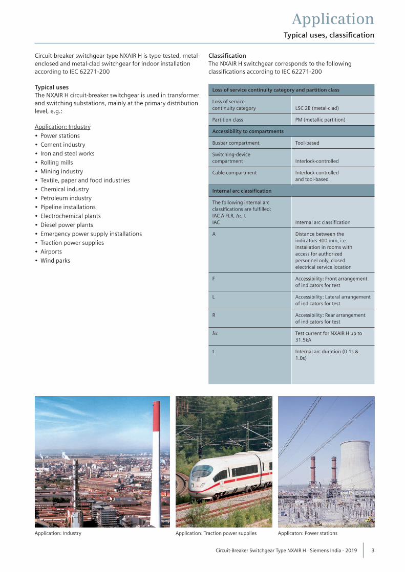
Application: Industry
• Power stations
• Cement industry
• Iron and steel works
• Rolling mills
• Mining industry
• Textile, paper and food industries
• Chemical industry
• Petroleum industry
• Pipeline installations
• Electrochemical plants
• Diesel power plants
• Emergency power supply installations
• Traction power supplies
• Airports
• Wind parks
ClassificationThe NXAIR H switchgear corresponds to the followingclassifications according to IEC 62271-200
Application: Industry Application: Traction power supplies Applicaton: Power stations
Loss of service continuity category and partition class
Loss of servicecontinuity category LSC 2B (metal-clad)
Partition class PM (metallic partition)
Accessibility to compartments
Busbar compartment Tool-based
Switching-devicecompartment Interlock-controlled
Cable compartment Interlock-controlledand tool-based
Internal arc classification
The following internal arcclassifications are fulfilled:IAC A FLR, Isc, tIAC Internal arc classification
A Distance between theindicators 300 mm, i.e.installation in rooms withaccess for authorizedpersonnel only, closedelectrical service location
F Accessibility: Front arrangement of indicators for test
L Accessibility: Lateral arrangementof indicators for test
R Accessibility: Rear arrangement of indicators for test
Isc Test current for NXAIR H up to 31.5kA
t Internal arc duration (0.1s & 1.0s)
3 Circuit-Breaker Switchgear Type NXAIR H · Siemens India - 2019
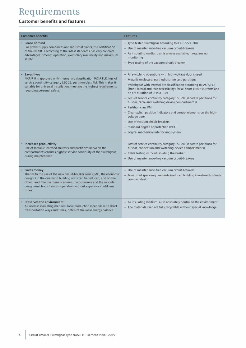
RequirementsCustomer benefits and features
Customer benefits Features
• Peace of mind For power supply companies and industrial plants, the certification
of the NXAIR H according to the latest standards has very concrete advantages: Smooth operation, exemplary availability and maximum safety.
– Type-tested switchgear according to IEC 62271-200
– Use of maintenance-free vacuum circuit-breakers
– As insulating medium, air is always available; it requires no monitoring
– Type testing of the vacuum circuit-breaker
• Saves lives NXAIR H is approved with internal arc classification IAC A FLR, loss of
service continuity category LSC 2B, partition class PM. This makes it suitable for universal installation, meeting the highest requirements regarding personal safety.
– All switching operations with high-voltage door closed
– Metallic enclosure, earthed shutters and partitions
– Switchgear with internal arc classification according to IAC A FLR (front, lateral and rear accessibility) for all short-circuit currents and an arc duration of 0.1s & 1.0s
– Loss of service continuity category LSC 2B (separate partitions for busbar, cable and switching device compartments)
– Partition class PM
– Clear switch position indicators and control elements on the high-voltage door
– Use of vacuum circuit-breakers
– Standard degree of protection IP4X
– Logical mechanical interlocking system
• Increases productivity Use of metallic, earthed shutters and partitions between the
compartments ensures highest service continuity of the switchgear during maintenance.
– Loss of service continuity category LSC 2B (separate partitions for busbar, connection and switching-device compartments)
– Cable testing without isolating the busbar
– Use of maintenance-free vacuum circuit-breakers
• Saves money Thanks to the use of the new circuit-breaker series 3AH, the economic
design. On the one hand building costs can be reduced, and on the other hand, the maintenance-free circuit-breakers and the modular design enable continuous operation without expensive shutdown times.
– Use of maintenance-free vacuum circuit-breakers
– Minimized space requirements (reduced building investments) due to compact design
• Preserves the environment Air used as insulating medium, local production locations with short
transportation ways and times, optimize the local energy balance.
– As insulating medium, air is absolutely neutral to the environment
– The materials used are fully recyclable without special knowledge
4 Circuit-Breaker Switchgear Type NXAIR H · Siemens India - 2019
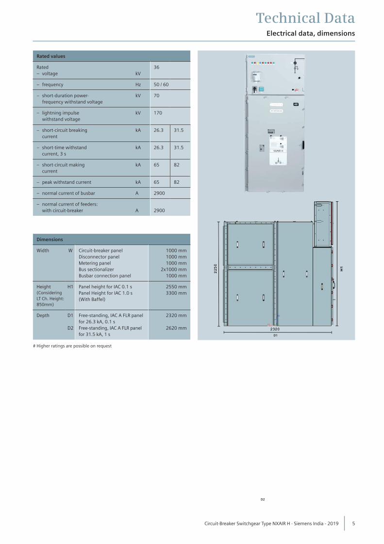
Technical DataElectrical data, dimensions
Rated values
Rated– voltage kV
36
– frequency Hz 50 / 60
– short-duration power- kV frequency withstand voltage
70
– lightning impulse kV withstand voltage
170
– short-circuit breaking kA current
26.3 31.5
– short-time withstand kA current, 3 s
26.3 31.5
– short-circuit making kA current
65 82
– peak withstand current kA 65 82
– normal current of busbar A 2900
– normal current of feeders: with circuit-breaker A 2900
Dimensions
Width W Circuit-breaker panelDisconnector panelMetering panelBus sectionalizerBusbar connection panel
1000 mm1000 mm1000 mm
2x1000 mm1000 mm
Height (Considering LT Ch. Height: 850mm)
H1 Panel height for IAC 0.1 sPanel Height for IAC 1.0 s (With Baffel)
2550 mm 3300 mm
Depth D1
D2
Free-standing, IAC A FLR panelfor 26.3 kA, 0.1 sFree-standing, IAC A FLR panel for 31.5 kA, 1 s
2320 mm
2620 mm
# Higher ratings are possible on request
D1
D2
5 Circuit-Breaker Switchgear Type NXAIR H · Siemens India - 2019
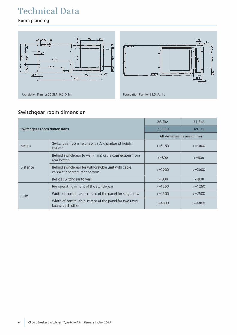
Technical DataRoom planning
Switchgear room dimension
Switchgear room dimensions
26.3kA 31.5kA
IAC 0.1s IAC 1s
All dimensions are in mm
HeightSwitchgear room height with LV chamber of height 850mm
>=3150 >=4000
Distance
Behind switchgear to wall (mm) cable connections from rear bottom
>=800 >=800
Behind switchgear for withdrawble unit with cable connections from rear bottom
>=2000 >=2000
Beside switchgear to wall >=800 >=800
Aisle
For operating infront of the switchgear >=1250 >=1250
Width of control aisle infront of the panel for single row >=2500 >=2500
Width of control aisle infront of the panel for two rows facing each other
>=4000 >=4000
Foundation Plan for 26.3kA, IAC: 0.1s Foundation Plan for 31.5 kA, 1 s
6 Circuit-Breaker Switchgear Type NXAIR H · Siemens India - 2019
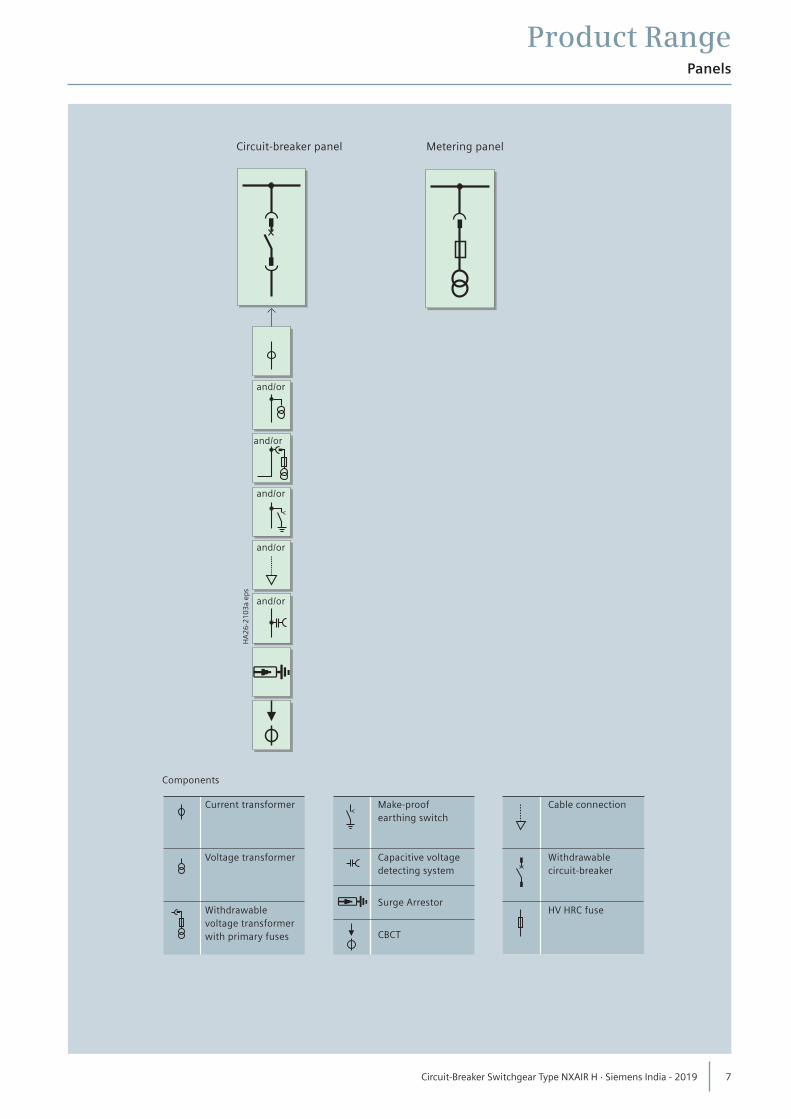
Product RangePanels
Components
Current transformer Make-proof Cable connection earthing switch
Withdrawable circuit-breaker
Voltage transformer
Capacitive voltage
HV HRC fuse
detecting system
Surge Arrestor
CBCT
Withdrawable
voltage transformer
with primary fuses
7 Circuit-Breaker Switchgear Type NXAIR H · Siemens India - 2019
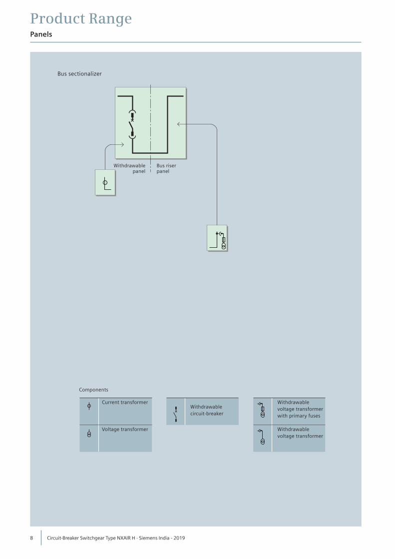
Product RangePanels
Components
Current transformer Withdrawable voltage transformer with primary fuses
Voltage transformer
Withdrawable
Withdrawable
circuit-breaker
voltage transformer
Bus sectionalizer
Withdrawablepanel
Bus riserpanel
8 Circuit-Breaker Switchgear Type NXAIR H · Siemens India - 2019
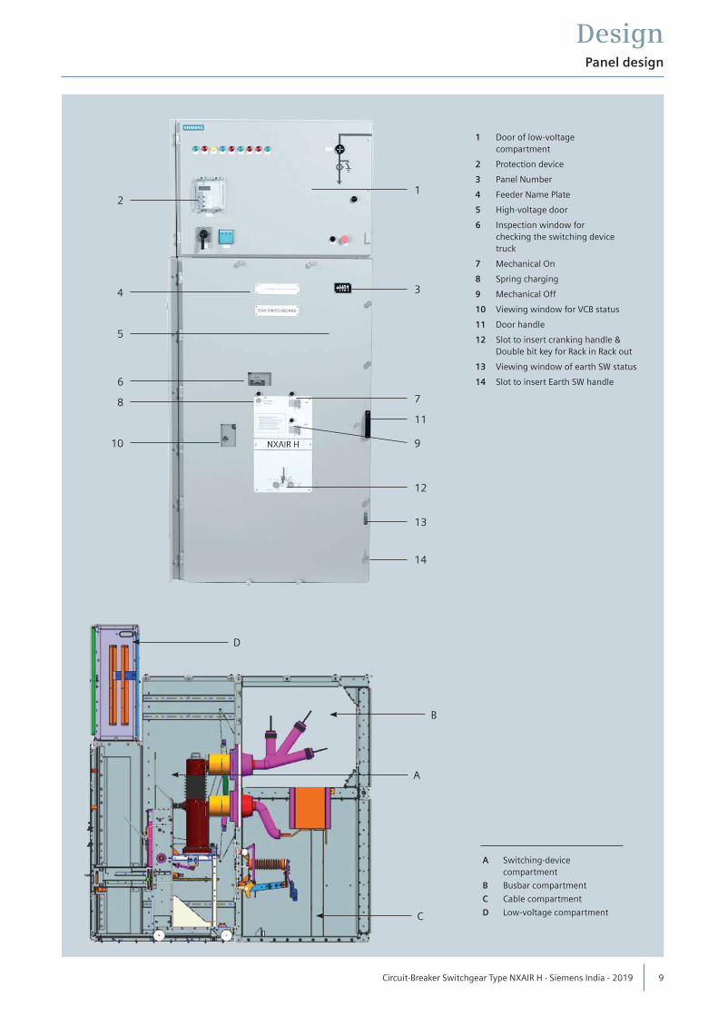
DesignPanel design
A Switching-device compartment
B Busbar compartment
C Cable compartment
D Low-voltage compartment
1 Door of low-voltage compartment
2 Protection device
3 Panel Number
4 Feeder Name Plate
5 High-voltage door
6 Inspection window for checking the switching device truck
7 Mechanical On
8 Spring charging
9 Mechanical Off
10 Viewing window for VCB status
11 Door handle
12 Slot to insert cranking handle & Double bit key for Rack in Rack out
13 Viewing window of earth SW status
14 Slot to insert Earth SW handle
21
3
7
11
9
12
13
14
4
5
6
8
10
D
B
C
A
9 Circuit-Breaker Switchgear Type NXAIR H · Siemens India - 2019
DesignPanel design
Switching-device compartment• All switching operations with high-voltage door closed• Pressure relief upwards• Panel powder-coated with epoxy resin• Metallic, earthed shutters ensure partition class PM• High-voltage door pressure-resistant in the event of internal
arcs in the panel• Interlocking between high-voltage door and circuit-breaker
truck ensures interlock-controlled access• Switching-device compartment to accommodate
components for implementing various panel versions with– Vacuum circuit-breaker truck– Metering truck.
Busbar compartment• Pressure relief upwards• Hollow triangular busbars– For rated normal current of up to 2900A– With Insulation & shrouds at joints• Bolted top covers provide tool-based access.
Cable compartment• Pressure relief upwards through rear pressure relief duct• Suitable for connection of single-core cables or Three core• Earthing busbar• Connection from rear • Interlocked high-voltage door and switching-device
compartment provide interlock-controlled tool-based access for panels with connection from rear
Components at the panel connection (option)• Single-core XLPE cables• Coupling electrode for capacitive voltage detecting system• Voltage transformers– Cast-resin insulated– Max. 3x1-pole– Fixed-mounted or Withdrawable• Earthing switch or earthing truck– Manual operating mechanism– In addition to standard interlocking between earthing
switch and circuit-breaker truck, optionally with padlock or electromagnetic interlocking
• Surge arresters– Protection of the switchgear against external over -
voltages.
Interlocks• Interlocking conditions are satisfied according to
IEC 62271-200• Earthing switch can only be operated with circuit-breaker
truck in test position• Circuit-breaker can only be moved with circuit-breaker
“OPEN” and earthing switch “OPEN”• Interlocking of high-voltage door against circuit-breaker
truck• The high-voltage door can only be opened when the
circuit-breaker truck is in test position• Option: Electromagnetic interlocking• Option: Mechanical key interlocking (based on interlocking scenarios).
10 Circuit-Breaker Switchgear Type NXAIR H · Siemens India - 2019
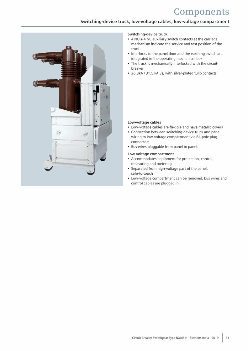
ComponentsSwitching-device truck, low-voltage cables, low-voltage compartment
Switching-device truck• 4 NO + 4 NC auxiliary switch contacts at the carriage
mechanism indicate the service and test position of the truck
• Interlocks to the panel door and the earthing switch are integrated in the operating mechanism box
• The truck is mechanically interlocked with the circuit-breaker
• 26.3kA / 31.5 kA 3s, with silver-plated tulip contacts.
Low-voltage cables• Low-voltage cables are flexible and have metallic covers• Connection between switching-device truck and panel
wiring to low-voltage compartment via 64-pole plug connectors
• Bus wires pluggable from panel to panel.
Low-voltage compartment• Accommodates equipment for protection, control,
measuring and metering• Separated from high-voltage part of the panel,
safe-to-touch• Low-voltage compartment can be removed, bus wires and
control cables are plugged in.
11 Circuit-Breaker Switchgear Type NXAIR H · Siemens India - 2019
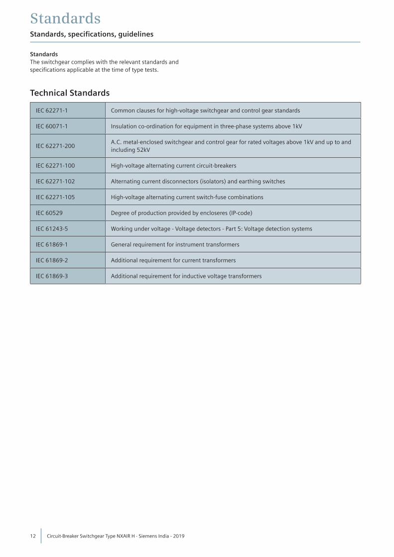
StandardsStandards, specifications, guidelines
StandardsThe switchgear complies with the relevant standards andspecifications applicable at the time of type tests.
Technical Standards
IEC 62271-1 Common clauses for high-voltage switchgear and control gear standards
IEC 60071-1 Insulation co-ordination for equipment in three-phase systems above 1kV
IEC 62271-200A.C. metal-enclosed switchgear and control gear for rated voltages above 1kV and up to and including 52kV
IEC 62271-100 High-voltage alternating current circuit-breakers
IEC 62271-102 Alternating current disconnectors (isolators) and earthing switches
IEC 62271-105 High-voltage alternating current switch-fuse combinations
IEC 60529 Degree of production provided by encloseres (IP-code)
IEC 61243-5 Working under voltage - Voltage detectors - Part 5: Voltage detection systems
IEC 61869-1 General requirement for instrument transformers
IEC 61869-2 Additional requirement for current transformers
IEC 61869-3 Additional requirement for inductive voltage transformers
12 Circuit-Breaker Switchgear Type NXAIR H · Siemens India - 2019
StandardsStandards, specifications, guidelines
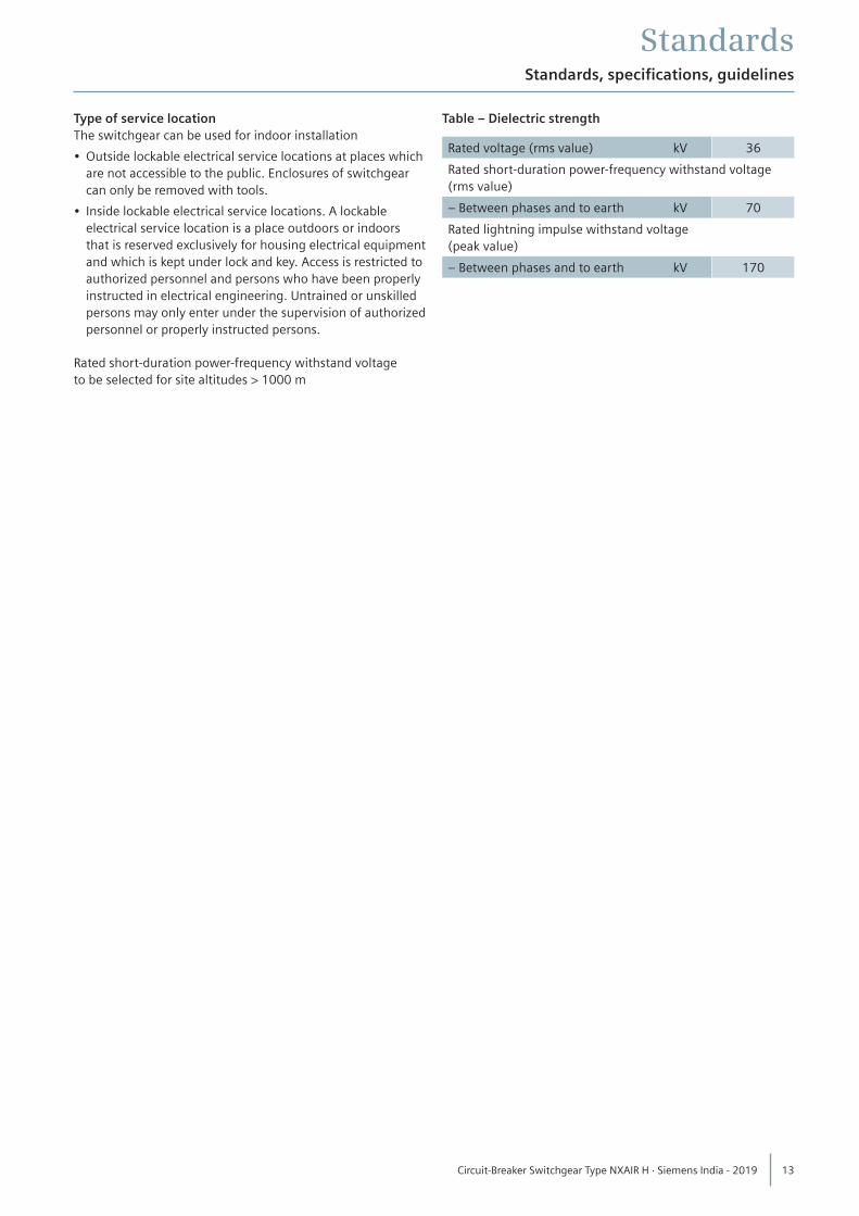
Type of service locationThe switchgear can be used for indoor installation
• Outside lockable electrical service locations at places which are not accessible to the public. Enclosures of switchgear can only be removed with tools.
• Inside lockable electrical service locations. A lockable electrical service location is a place outdoors or indoors that is reserved exclusively for housing electrical equipment and which is kept under lock and key. Access is restricted to authorized personnel and persons who have been properly instructed in electrical engineering. Untrained or unskilled persons may only enter under the supervision of authorized personnel or properly instructed persons.
Rated short-duration power-frequency withstand voltageto be selected for site altitudes > 1000 m
Table – Dielectric strength
Rated voltage (rms value) kV 36
Rated short-duration power-frequency withstand voltage(rms value)
– Between phases and to earth kV 70
Rated lightning impulse withstand voltage(peak value)
– Between phases and to earth kV 170
13 Circuit-Breaker Switchgear Type NXAIR H · Siemens India - 2019
StandardsStandards, specifications, guidelines
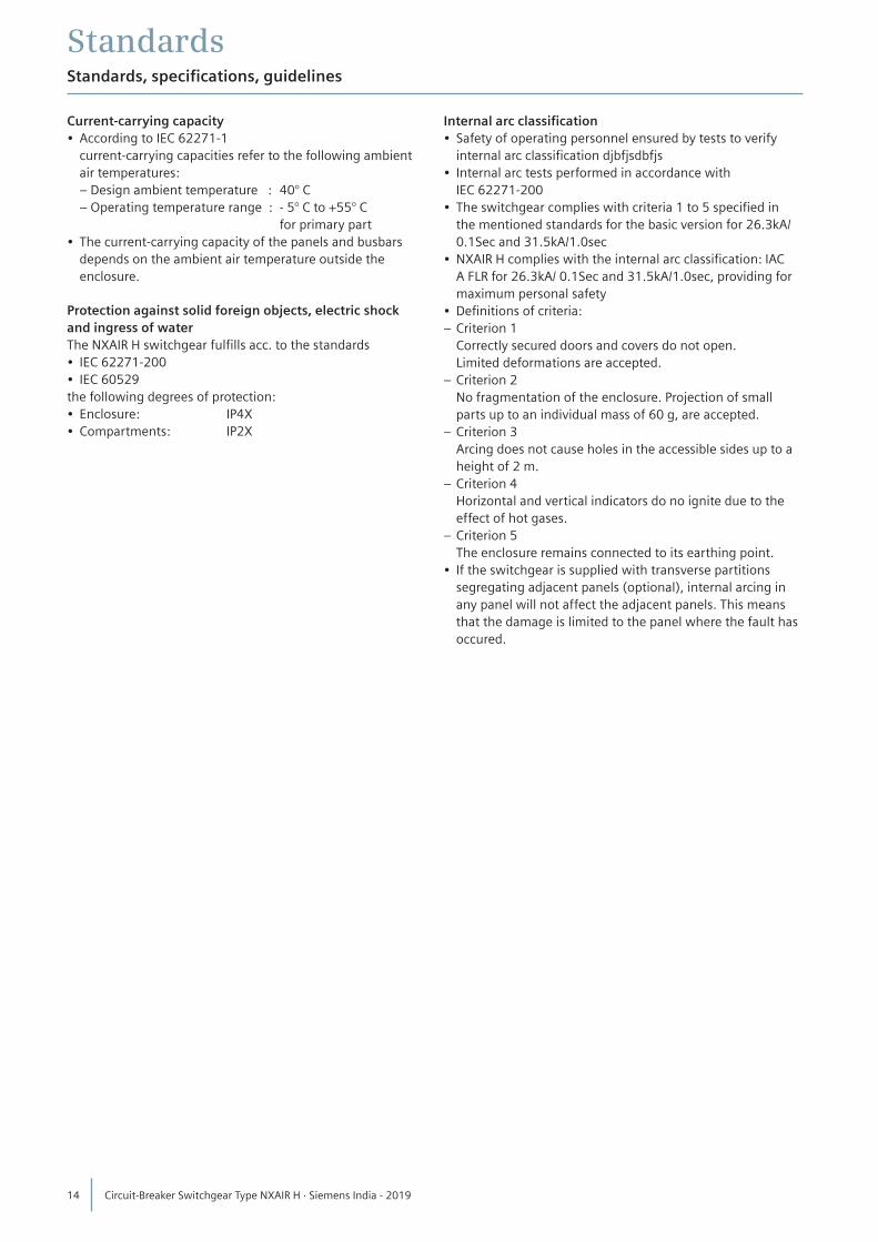
Current-carrying capacity• According to IEC 62271-1 current-carrying capacities refer to the following ambient
air temperatures: – Design ambient temperature : 40° C – Operating temperature range : - 5° C to +55° C
for primary part• The current-carrying capacity of the panels and busbars
depends on the ambient air temperature outside the enclosure.
Protection against solid foreign objects, electric shockand ingress of waterThe NXAIR H switchgear fulfills acc. to the standards• IEC 62271-200• IEC 60529the following degrees of protection:• Enclosure: IP4X• Compartments: IP2X
Internal arc classification• Safety of operating personnel ensured by tests to verify
internal arc classification djbfjsdbfjs• Internal arc tests performed in accordance with
IEC 62271-200 • The switchgear complies with criteria 1 to 5 specified in
the mentioned standards for the basic version for 26.3kA/ 0.1Sec and 31.5kA/1.0sec
• NXAIR H complies with the internal arc classification: IAC A FLR for 26.3kA/ 0.1Sec and 31.5kA/1.0sec, providing for maximum personal safety
• Definitions of criteria:– Criterion 1 Correctly secured doors and covers do not open. Limited deformations are accepted.– Criterion 2 No fragmentation of the enclosure. Projection of small
parts up to an individual mass of 60 g, are accepted.– Criterion 3 Arcing does not cause holes in the accessible sides up to a
height of 2 m.– Criterion 4 Horizontal and vertical indicators do no ignite due to the
effect of hot gases.– Criterion 5 The enclosure remains connected to its earthing point.• If the switchgear is supplied with transverse partitions
segregating adjacent panels (optional), internal arcing in any panel will not affect the adjacent panels. This means that the damage is limited to the panel where the fault has occured.
14 Circuit-Breaker Switchgear Type NXAIR H · Siemens India - 2019
Notes
15 Circuit-Breaker Switchgear Type NXAIR H · Siemens India - 2019
2019
Published bySiemens India
Product upgradation is a continuous process. Hence, data in this catalog is subject to change without prior notice. For the latest information, please get in touch with our Sales Offices.
Siemens LimitedEnergy Management DivisionMedium Voltage & SystemsKalwa Works Tel.: +91 22 3966 8380
www.siemens.com
Subject to changes and errors. The information given in this document only contains general descriptions and/or performance features which may not always specifically reflect those described, or which may undergo modification in the course of further development of the products. The requested performance features are binding only when they are expressly agreed upon in the concluded contract.