obuchenie zelio logic modbus ethernet extensions en
TRANSCRIPT

Slide 1 / 25Automation - Product Support - TrainingPhB - Zelio Logic Extension Com en 11/2006
Zelio Logic - Communication Extension
A
B
C
D Ethernet extension set up
Modbus extension set up
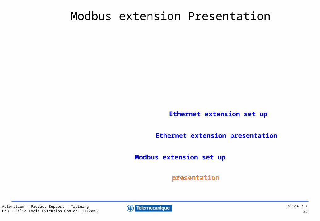
Modbus extension presentation
Ethernet extension presentation
Slide 2 / 25Automation - Product Support - TrainingPhB - Zelio Logic Extension Com en 11/2006
Modbus extension presentationModbus extension presentationModbus extension presentation
Modbus extension Presentation
A
B
C
D Ethernet extension set up
Modbus extension set up
Ethernet extension presentation

Slide 3 / 25Automation - Product Support - TrainingPhB - Zelio Logic Extension Com en 11/2006
With modular Zelio Logic power supply 24 VDC
Modbus slave not electrically isolated, RTU/ASCII
protocol
Configuration : Zelio HMI or Zelio- Soft
– Number of wires = 2, 4
– Frames format = RTU or ASCII
– Speed = 1200, 2400,…,19200,…,57600
– Parity = none, even, odd
– Address = 1 to 247 In bold =>
factory settingSR3 MBU01BDSR3 B...BD
+
Zelio logic connected on modbus via the Modbus extension module
Characteristics
Slide 4 / 25Automation - Product Support - TrainingPhB - Zelio Logic Extension Com en 11/2006
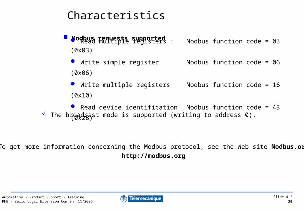
Modbus requests supported
Read multiple registers : Modbus function code = 03 (0x03)
Write simple register Modbus function code = 06 (0x06)
Write multiple registers Modbus function code = 16 (0x10)
Read device identification Modbus function code = 43 (0x2B)
The broadcast mode is supported (writing to address 0).
To get more information concerning the Modbus protocol, see the Web site Modbus.org
http://modbus.org
Characteristics

Slide 5 / 25Automation - Product Support - TrainingPhB - Zelio Logic Extension Com en 11/2006
1 Mounting : on rail 35mm, retractable mounting feet,
2 Connector RJ45 : Modbus fieldbus connection
3 DEL « COM » : communication status
4 DEL « PWR » : Product powered or in fault
5 Screw for connection to the protection ground
SR3 MBU01BD
5
1
23
4
Pin number of connector RJ45
2 wires Modbus 4 wires Modbus
1 NC RXD02 NC RXD13 NC NC4 D1 TXD15 D0 TXD06 NC NC7 NC NC8 Common Common
Front panel
Description

Slide 6 / 25Automation - Product Support - TrainingPhB - Zelio Logic Extension Com en 11/2006
1 Twido compact+Port COM RS485 miniDIN
2 Zelio logic and extension modbus
3 Line end of 120 ohms
4 T junction : VW3A8306R
5 Cable 3m mini-DIN and RJ45 : TWDXCARJ030
6 Cable with 2 RJ45 connectors: VW3A306R..
1
34
5
34 4
2 2 2
Twido (modbus master)
6 6 6
31 modbus slaves maximum
5 5
Connection example
Connection with T junction

Slide 7 / 25Automation - Product Support - TrainingPhB - Zelio Logic Extension Com en 11/2006
Modbus extension presentation
Modbus extension set up
A
B
C
D Ethernet extension set up
Modbus extension set up
Ethernet extension presentation
Modbus extension set up
Slide 8 / 25Automation - Product Support - TrainingPhB - Zelio Logic Extension Com en 11/2006
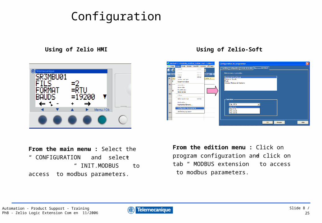
From the main menu : Select the
“ CONFIGURATION ” and select
“ INIT.MODBUS ” to access to modbus
parameters.
Using of Zelio HMI
From the edition menu : Click on program
configuration and click on tab “ MODBUS
extension ” to access to modbus parameters.
Using of Zelio-Soft
Configuration

Slide 9 / 25Automation - Product Support - TrainingPhB - Zelio Logic Extension Com en 11/2006
Modbus exchanges are implicit and transparent for Zelio.
The Zelio application data are not accessible by the master.
Modbus exchangesModbus
function codeModbus registers
Read of Zelio Inputs/Outputs 03 (read multiple words)
Word 20 : base inputs I1 to IGWord 21 : extension inputs IH to IRWord 22 : base outputs Q1 to QAWord 23 : extension outpus QB to QG
Read/Write of Zelio clock03 (read multiple words)
06 (write single word)16 (write multiple word)
Word 32 : Day of the week, SecondeWord 33 : Minutes, HoursWord 34 : Day of the month, MonthWord 35 : Year, century
Read Status of Zelio module 03 (read multiple words)
Word 48 : bit 0 = Run/Stop, bit 1 = Monitoring, bit 2 = Alarm, bit 3 = Error, bit 7 = Time out bit 8 à F = Alarm code
Ladder language - LADDER
Modbus exchanges
Slide 10 / 25Automation - Product Support - TrainingPhB - Zelio Logic Extension Com en 11/2006
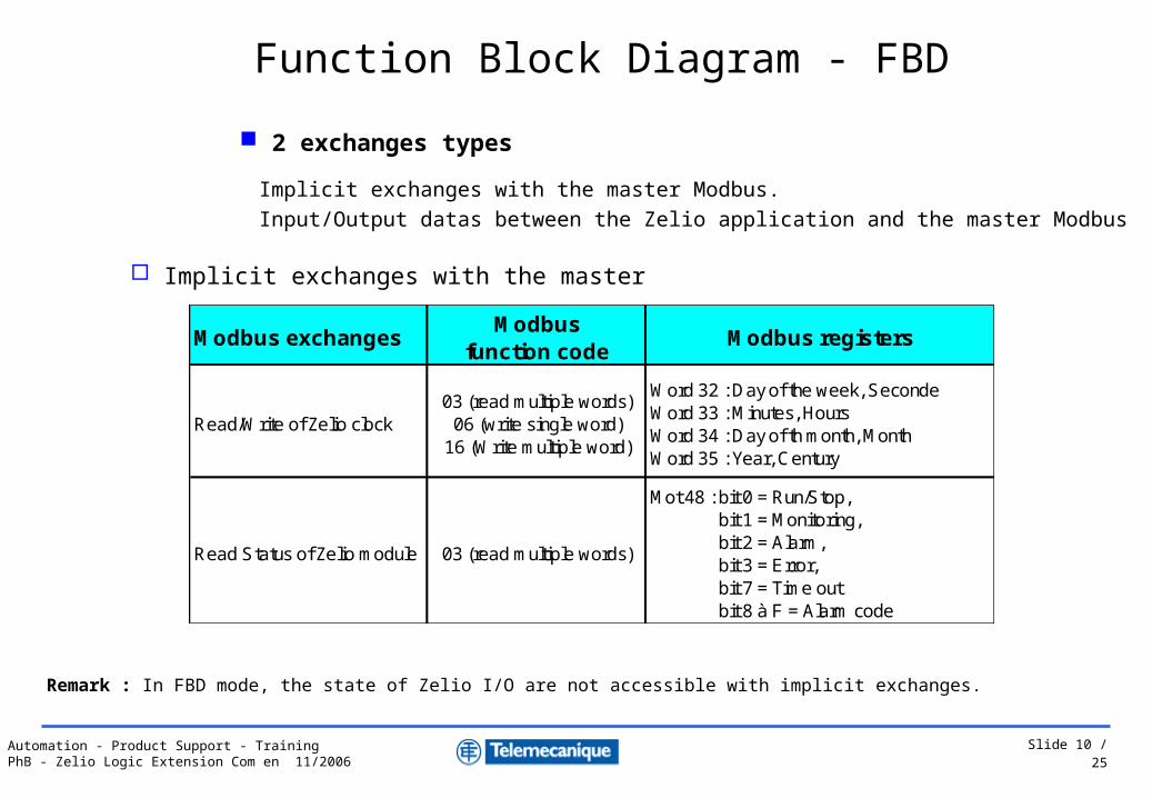
Implicit exchanges with the master Modbus.
Input/Output datas between the Zelio application and the master Modbus
Implicit exchanges with the master
Remark : In FBD mode, the state of Zelio I/O are not accessible with implicit exchanges.
Modbus exchangesModbus
function codeModbus registers
Read/Write of Zelio clock03 (read multiple words)
06 (write single word)16 (Write multiple word)
Word 32 : Day of the week, SecondeWord 33 : Minutes, HoursWord 34 : Day of th month, MonthWord 35 : Year, Century
Read Status of Zelio module 03 (read multiple words)
Mot 48 : bit 0 = Run/Stop, bit 1 = Monitoring, bit 2 = Alarm, bit 3 = Error, bit 7 = Time out bit 8 à F = Alarm code
2 exchanges types
Function Block Diagram - FBD
Slide 11 / 25Automation - Product Support - TrainingPhB - Zelio Logic Extension Com en 11/2006
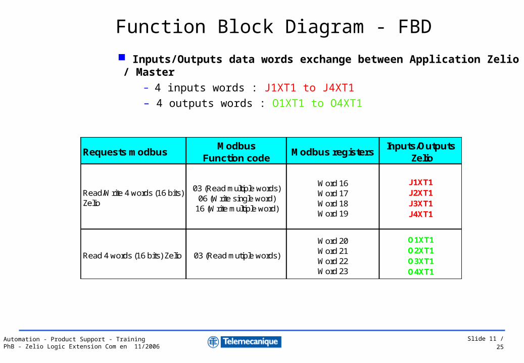
Inputs/Outputs data words exchange between Application Zelio / Master– 4 inputs words : J1XT1 to J4XT1– 4 outputs words : O1XT1 to O4XT1
Requests modbusModbus
Function codeModbus registers
Inputs/Outputs Zelio
Read/Write 4 words (16 bits) Zelio
03 (Read multiple words)06 (Write single word)
16 (Write multiple word)
Word 16Word 17Word 18Word 19
J1XT1J2XT1J3XT1J4XT1
Read 4 words (16 bits) Zelio 03 (Read mutiple words)
Word 20Word 21Word 22Word 23
O1XT1O2XT1O3XT1O4XT1
Function Block Diagram - FBD

Slide 12 / 25Automation - Product Support - TrainingPhB - Zelio Logic Extension Com en 11/2006
4 words J1XT1 to J4XT1 accessible in
reading/writing by the master
OUTPUT
INPUT
4 words O1XT1to O4XT1 accessible in
reading by the master
Screen of FBD Editor
Function Block Diagram - FBD
Inputs/Outputs data words exchange between Application Zelio / Master
Slide 13 / 25Automation - Product Support - TrainingPhB - Zelio Logic Extension Com en 11/2006
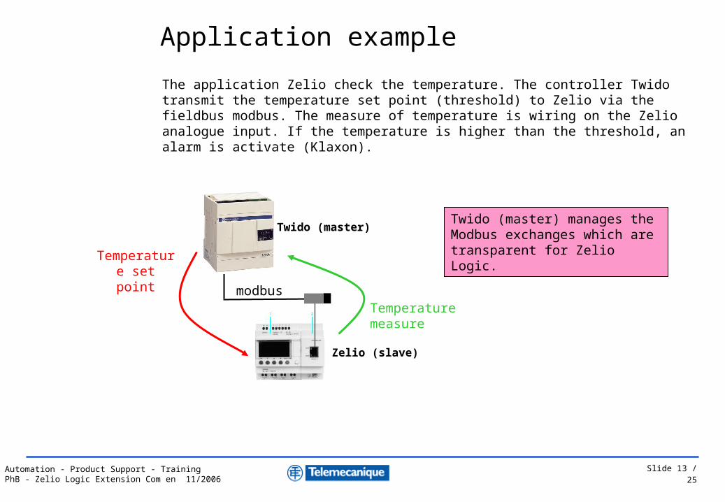
The application Zelio check the temperature. The controller Twido transmit the temperature set point (threshold) to Zelio via the fieldbus modbus. The measure of temperature is wiring on the Zelio analogue input. If the temperature is higher than the threshold, an alarm is activate (Klaxon).
Twido (master)
Zelio (slave)
Temperature set point
Temperature measure
modbus
Twido (master) manages the Modbus exchanges which are transparent for Zelio Logic.
Application example

Slide 14 / 25Automation - Product Support - TrainingPhB - Zelio Logic Extension Com en 11/2006
Using the input word J1XT1 to write the temperature set point and the output word O1XT1 to read the measure.
Writing of the set point in the input
word J1XT1 by the modbus master
Reading of the measure in the
output word O1XT1 by the modbus
master
Application example
Slide 15 / 25Automation - Product Support - TrainingPhB - Zelio Logic Extension Com en 11/2006
Ethernet extension presentation
A
B
C
D Ethernet extension set up
Modbus extension set up
Modbus extension presentation
Ethernet extension presentationEthernet extension presentation
Ethernet extension presentation

Slide 16 / 25Automation - Product Support - TrainingPhB - Zelio Logic Extension Com en 11/2006
Zelio logic on Ethernet via the Ethernet extension module
Compatible Zelio Logic modular 24 VDC
Connecteur RJ45 10/100 T
Modbus TCP/IP server
Adresse IP : acquisition static or dynamic
Configuration : Zelio Soft 2, FBD language
SR3 NET01BDSR3 B...BD
+
Characteristics

Slide 17 / 25Automation - Product Support - TrainingPhB - Zelio Logic Extension Com en 11/2006
Modbus TCP/IP request supported
Reading of n register Function code = 03 (0x03)
Writing of simple registers Function code = 06 (0x06)
Writing of n registers Function code code = 16 (0x10)
Reading device identification Function code code = 43 (0x2B)
Characteristics
Slide 18 / 25Automation - Product Support - TrainingPhB - Zelio Logic Extension Com en 11/2006
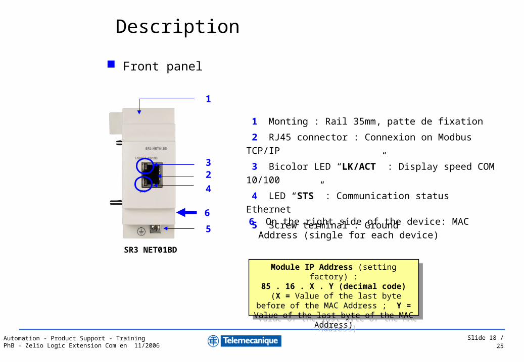
1 Monting : Rail 35mm, patte de fixation
2 RJ45 connector : Connexion on Modbus TCP/IP
3 Bicolor LED “LK/ACT” : Display speed COM 10/100
4 LED “STS” : Communication status Ethernet
5 Screw terminal : Ground
5
1
23
4
Front panel
Description
SR3 NET01BD
Module IP Address (setting factory) :85 . 16 . X . Y (decimal code)
(X = Value of the last byte before of the MAC Address ; Y = Value of the last byte of
the MAC Address)
Module IP Address (setting factory) :85 . 16 . X . Y (decimal code)
(X = Value of the last byte before of the MAC Address ; Y = Value of the last byte of
the MAC Address)
66 On the right side of the device: MAC Address (single for
each device)

Slide 19 / 25Automation - Product Support - TrainingPhB - Zelio Logic Extension Com en 11/2006
1 Twido compact : TWDLCAE40DRF
2 Ethernet cable RJ45 connector : 490 NTW000 ..
3 Switch conneXium 499 NES251 00
4 Zelio logic modular : SR3B…BD
5 Ethernet extension module : SR3NET01BD
1
2
Twido Compact (client)
Connection example
Ethernet Architecture
32
2
4 5
Zelio Logic (server)
Zelio Logic (server)
Slide 20 / 25Automation - Product Support - TrainingPhB - Zelio Logic Extension Com en 11/2006
A
B
C
D
Ethernet extension set up
Ethernet extension set up
Modbus extension set up
Modbus extension presentation
Ethernet extension presentation
Ethernet extension set up

Slide 21 / 25Automation - Product Support - TrainingPhB - Zelio Logic Extension Com en 11/2006
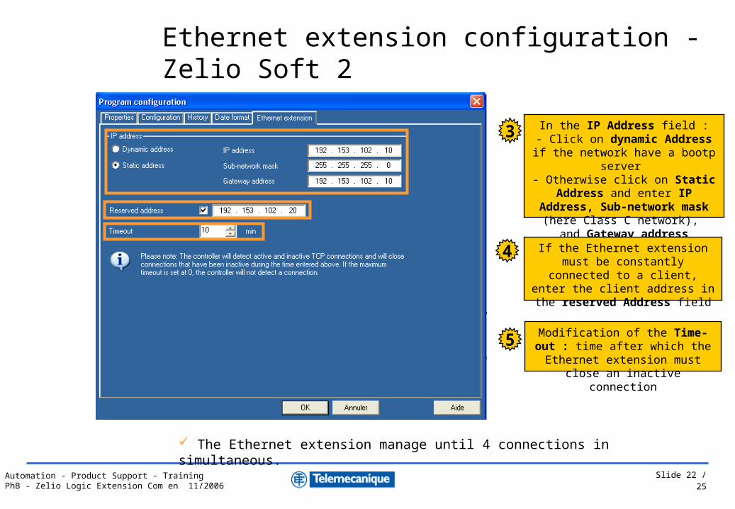
Ethernet extension configuration - Zelio Soft 2
Menu edition : Select “Program configuration”1
FBD Language
Menu Program configuration : Click on tab Ethernet extension2
Slide 22 / 25Automation - Product Support - TrainingPhB - Zelio Logic Extension Com en 11/2006
In the IP Address field :- Click on dynamic Address if the
network have a bootp server - Otherwise click on Static Address and enter IP Address, Sub-network mask (here Class C network), and
Gateway address
3
The Ethernet extension manage until 4 connections in simultaneous.
If the Ethernet extension must be constantly connected to a client,
enter the client address in the reserved Address field
4
Modification of the Time-out : time after which the Ethernet extension must close an inactive connection
5
Ethernet extension configuration - Zelio Soft 2

Slide 23 / 25Automation - Product Support - TrainingPhB - Zelio Logic Extension Com en 11/2006
Data words accessibles via application Zelio
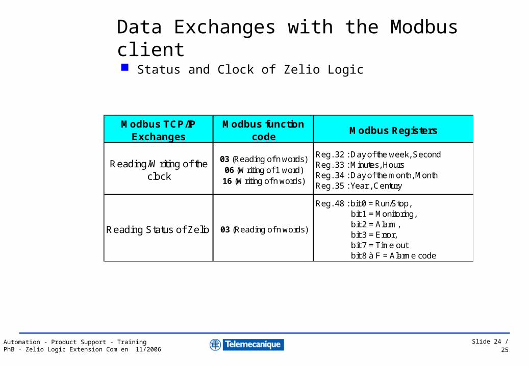
Data Exchanges with the Modbus client
Modbus TCP/IPExchanges
Modbus functioncode
Modbus register Input/Output Zelio Logic
4 Input words(16 bits)
03 (Reading n words)06 (Writning 1 word16 (Writing n words)
Reg. 16Reg. 17Reg. 18Reg. 19
J1XT1J2XT1J3XT1J4XT1
4 Output words(16 bits)
03 (Reading n words)
Reg. 20Reg. 21Reg. 22Reg. 23
O1XT1O2XT1O3XT1O4XT1
4 Input words : J1XT1 to J4XT1
4 Output words : O1XT1 to O4XT1
Slide 24 / 25Automation - Product Support - TrainingPhB - Zelio Logic Extension Com en 11/2006
Status and Clock of Zelio Logic
Modbus TCP/IPExchanges
Modbus function code
Modbus Registers
Reading/Writing of the clock
03 (Reading of n words)06 (Writing of 1 word)16 (Writing of n words)
Reg. 32 : Day of the week, SecondReg. 33 : Minutes, HoursReg. 34 : Day of the month, MonthReg. 35 : Year , Century
Reading Status of Zelio 03 (Reading of n words)
Reg. 48 : bit 0 = Run/Stop, bit 1 = Monitoring, bit 2 = Alarm, bit 3 = Error, bit 7 = Time out bit 8 à F = Alarme code
Data Exchanges with the Modbus client
Slide 25 / 25Automation - Product Support - TrainingPhB - Zelio Logic Extension Com en 11/2006
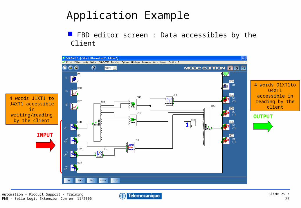
4 words J1XT1 to J4XT1 accessible in
writing/reading by the client
4 words O1XT1to O4XT1 accessible in reading by the client
FBD editor screen : Data accessibles by the Client
Application Example
INPUT
OUTPUT