operations and maintenance manual wireline … panel manual 2018-03-13.pdfcall benchmark wireline...
TRANSCRIPT

40/50 SERIES PANEL MARCH 2018 Page 1 of 60
OPERATIONS AND MAINTENANCE MANUAL WIRELINE WINCH OPERATORS PANEL
AMD2A040 and AMD2A050
COMBINED NEW 40 & 50 Series Panels
These Panels Replace All Previous 40 - 50 - 60 Series Panels

40/50 SERIES PANEL MARCH 2018 Page 2 of 60
TABLE OF CONTENTS ___________________________________________
1.0 Introduction
2.0 Features
3.0 Operation
4.0 Spare Parts
5.0 Specifications
6.0 Cables

40/50 SERIES PANEL MARCH 2018 Page 3 of 60
OBTAINING TECHNICAL ASSISTANCE
Call BenchMark Wireline Products Inc. at +1 281 346 4300 Or contact by email [email protected] Or fax in request at +1 281 346 4301 Information in the form of user manuals and instructional videos are also available on our website www.benchmarkwireline.com Parts can be ordered by email, phone, or fax Equipment can be returned for repair and maintenance. Please notify us by Phone, email, or fax before sending any equipment. To return equipment to BenchMark, ship it to: BenchMark Wireline Products 36220 FM 1093 Simonton, Texas 77476 U.S.A.

40/50 SERIES PANEL MARCH 2018 Page 4 of 60
1.0 INTRODUCTION
The new 40/50 series replace all previous 40 50 60 models

40/50 SERIES PANEL MARCH 2018 Page 5 of 60
The new AMD2A040 and 050 Wireline Winch Operator’s Panels from BenchMark Wireline are a great step forward in the design and functionality of these devices. Building on many years of experience in designing and manufacturing these products, they have combined their knowledge and experiences with the latest technology to design and build the finest operator’s panels in the industry. Our totally new design uses the latest solid-state digital technology to build a product that is smarter, more capable, more robust, simpler. The capabilities have been expanded, the reliability has been increased and the price to our customer has been reduced. This panel is designed to acquire and display depth and tension data from a wireline winch unit. The panel uses a menu system to set and make adjustments to the data as necessary.
Depth is displayed from data provided from an encoder mounted on a measuring device. The tension data is provided by a load pin. Depth and tension data can be stored in internal memory for playback at a later time. The panel can also be connected to a PC through a serial port for real time acquisition and playback of data.
The system is designed to operate properly from conventional automotive 12-24 vdc electrical power.
Loss of power to the panel during operation will not cause a loss of depth data. The panel continuously stores depth data every 100 milliseconds in and internal battery backed up memory device. When power is applied, the last "Depth" is displayed.

40/50 SERIES PANEL MARCH 2018 Page 6 of 60
2.0 FEATURES
2.1 FEATURES SUMMARY - both models contain all features of former 40-50-60 model panels - new 40-50 models are functionally identical – only difference is form factor - new operating system is purpose-built for this application and supersedes cumbersome Windows software - completely solid-state design with no moving or mechanical parts - super high reliability machine-assembled PCB - electrical connections machine assembled – no more manual wiring harnesses - digital readouts and dials replacing mechanical dials and 7 segment digits - standardized back panels that contain all possible Signal ID - operational redundancy allows it to operate on any one screen if necessary - software upgrades executable in minutes through USB - ergonomic display choices for operators - administrative password controlled lock-out of key functions - panels are suitable for both wireline and slickline work Note – The Left Screen on the 40 is the same as the Top Screen on the 50 The Right Screen on the 40 is the same as the Bottom Screen on the 50

40/50 SERIES PANEL MARCH 2018 Page 7 of 60
2.2 FEATURES GUIDE Main Displays
The above configuration is the default display of the AMD2A040. The display contains
Depth, Tension and Linespeed, as well as current time in the lower right corner.
The left screen contains the differential tension meter which can be set in either
Differential or Incremental mode. The yellow dots indicate differential tension alarm
settings. The Zero Depth button will set depth to 0, but can be pressed again to see
the previous depth.
The right screen contains the Total Tension meter which contains indicators for both
Total Tension Alarm and Total Tension Shutdown.

40/50 SERIES PANEL MARCH 2018 Page 8 of 60
Dark Screen or Light Screen Display Depending on the working environment and operator preferences, the panels can be
setup with either a dark background or light background screen.

40/50 SERIES PANEL MARCH 2018 Page 9 of 60
2.3 DISPLAY ALERTS
Both Displays have dynamic alerts that are displayed above. The alarms and shutdowns will enable visual cues to the operator. The approaching surface alarm will change the depth display to Alert Yellow and flash an Approaching Surface message. Both Tension Gauges have color changing bezels to alert the operator that an alarm has been initiated. The right screen will display an Excessive Tension message when the Total Tension alarm is initiated.
The right screen will also change both the digital display and the bezel to RED if the shutdown condition is met, as well as display a Shutdown message as shown.

40/50 SERIES PANEL MARCH 2018 Page 10 of 60
2.4 BACKUP MODE (Can be selected in the Admin Menu)
Both Displays are capable of running independently as shown. This allows the operator to continue work in the event of a damaged display or error. This mode allows the operator to see Depth, Tension, Line Speed, and Differential tension all on one screen.
It also changes the menu system to display all menus on a single screen.

40/50 SERIES PANEL MARCH 2018 Page 11 of 60
2.5 LEFT SCREEN MENUS When in normal mode the Left Screen Menu is intended to include the menus that would be changed most often. See the following screens.
In this Menu you can select any of the above settings to change. Brightness will toggle the panel to a higher brightness mode for sunlight readability. The Help menu is available in both the Left and Right Menus.
40/50 SERIES PANEL MARCH 2018 Page 12 of 60
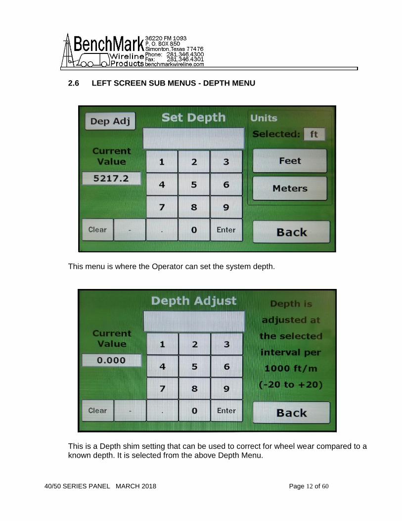
2.6 LEFT SCREEN SUB MENUS - DEPTH MENU
This menu is where the Operator can set the system depth.
This is a Depth shim setting that can be used to correct for wheel wear compared to a known depth. It is selected from the above Depth Menu.

40/50 SERIES PANEL MARCH 2018 Page 13 of 60
2.7 TENSION MENU
The Tension menu is where the Operator can Calibrate Tension, select the left meter setting between differential and incremental tension, set units, enable/disable stretch correction, and set the scale values for both meters.
This menu is selected via the Tension menu and is used to set the scales displayed on both Meters.

40/50 SERIES PANEL MARCH 2018 Page 14 of 60
2.8 LINE SIZE
This is the standard line selection menu and is dependent on the Head Type selected.

40/50 SERIES PANEL MARCH 2018 Page 15 of 60
2.9 ALARMS
These four menus are selected by pressing the correlating menu button on the right hand side. The operator sets these values and the Dynamic Display alerts are automatically adjusted.
40/50 SERIES PANEL MARCH 2018 Page 16 of 60
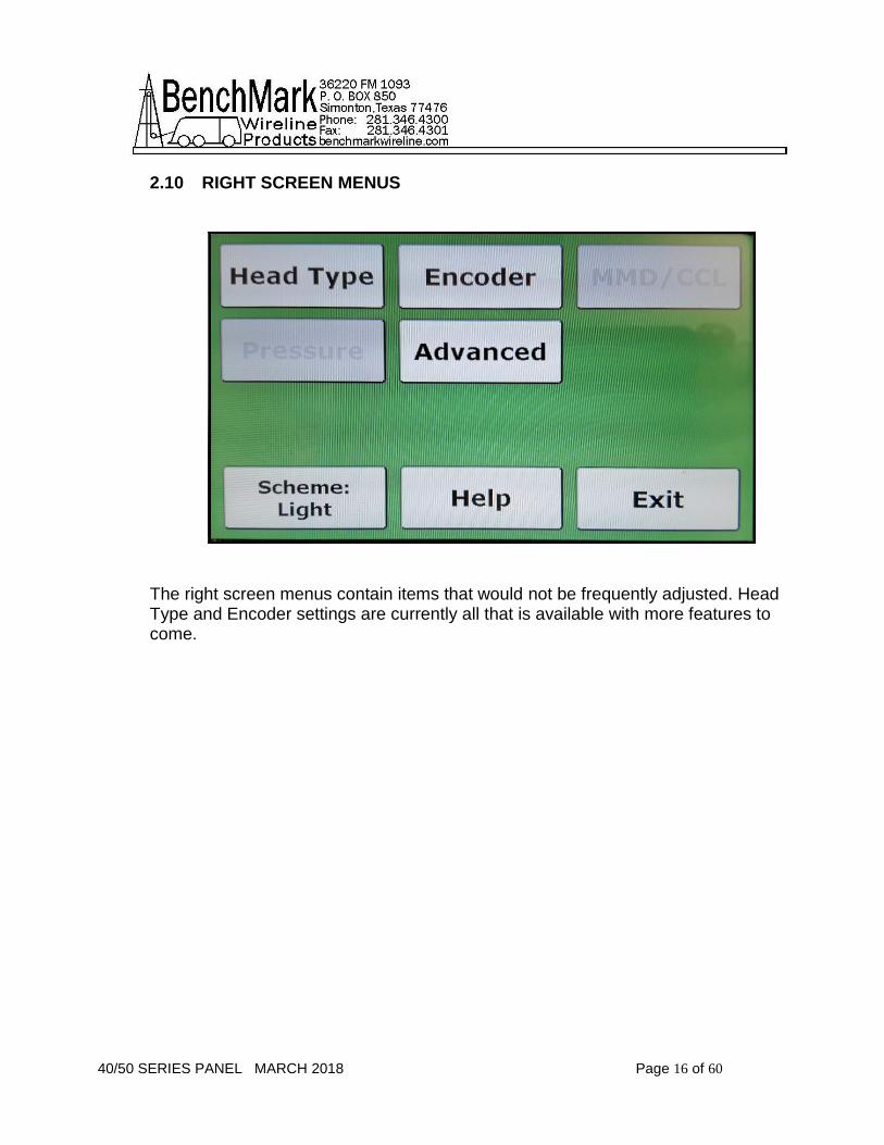
2.10 RIGHT SCREEN MENUS
The right screen menus contain items that would not be frequently adjusted. Head Type and Encoder settings are currently all that is available with more features to come.

40/50 SERIES PANEL MARCH 2018 Page 17 of 60
2.11 HEAD TYPE
This panel is capable of both Wireline and Slickline, requiring the operator to select the measuring head the system will be reading.

40/50 SERIES PANEL MARCH 2018 Page 18 of 60
2.12 LOAD CELL
This panel also allows for many different Load Cell types and can be changed in this menu. An option to have 2 different load cells will be available in the future.

40/50 SERIES PANEL MARCH 2018 Page 19 of 60
2.13 ENCODER
This menu allows the operator to select between encoders, and select depth units, as well as set the Optical Encoder incoming and outgoing pulse rates.

40/50 SERIES PANEL MARCH 2018 Page 20 of 60
2.14 ENCODER INPUT
This menu is to set the Encoder Pulse rate to match the Optical Encoder on the measuring head. The operator can select from a list of common BenchMark pulse rates on the right, or enter a new value manually.

40/50 SERIES PANEL MARCH 2018 Page 21 of 60
2.15 ENCODER OUTPUT
This menu is to select the output pulses that will be sent to a logging system such as Warrior.

40/50 SERIES PANEL MARCH 2018 Page 22 of 60
2.16 OTHER MENUS – HELP
The help menu allows the operator to see the model number, software versions for troubleshooting, and contact information for BenchMark Wireline Products. It also contains the buttons to get to Admin controls and Summary.

40/50 SERIES PANEL MARCH 2018 Page 23 of 60
2.17 ADMIN
The Admin menu is a new feature introduced in this panel. It allows the operator to get to the Backup Mode Select, but also allows the Supervisor to have additional control over the panel which was not available in previous versions. The default PIN is 00000 and can be set to a custom value once inside the ADMIN system.
40/50 SERIES PANEL MARCH 2018 Page 24 of 60
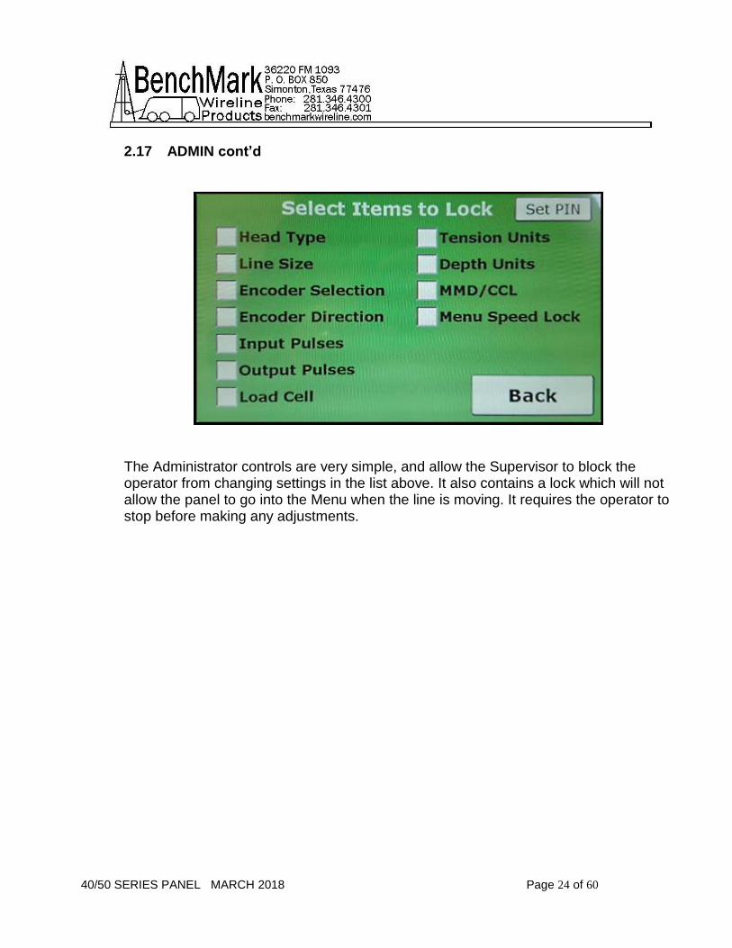
2.17 ADMIN cont’d
The Administrator controls are very simple, and allow the Supervisor to block the operator from changing settings in the list above. It also contains a lock which will not allow the panel to go into the Menu when the line is moving. It requires the operator to stop before making any adjustments.

40/50 SERIES PANEL MARCH 2018 Page 25 of 60
2.18 SET PIN
This menu allows the Supervisor to set a unique PIN between 4 and 8 digits long. The current PIN is displayed at the bottom of the screen. If the PIN is lost the Supervisor may contact BenchMark for instructions to access the system.

40/50 SERIES PANEL MARCH 2018 Page 26 of 60
2.19 SUMMARY
This is a quick way to see all current settings in the panel, and can be accessed via the HELP menu which is available on both displays. 2.20 MMD/CCL

40/50 SERIES PANEL MARCH 2018 Page 27 of 60
This menu allows the operator to switch between MMD and CCL inputs. Adjust CCL voltage with the +/-. Set MMD Window at 50ft and100ft or 10m, 20m, 25m, 50m. 2.21 PRESSURE
This menu allows the operator to turn pressures on or off, zero each pressure, adjust fullscale, and change units. When pressures are on the main screen will display the individual pressures below Tension.

40/50 SERIES PANEL MARCH 2018 Page 28 of 60
3.0 OPERATIONS - INITIAL PANEL SETUP - JOB SETUP
Both the 40 and 50 panels contain the same functionality and readouts. The only difference is the form factor/shape which allows mounting the panel in different work environments. The 2 display screens contain different information. The left or top screen displays Depth, Line Speed and Differential Tension. The right shows Total Tension and has options for setting-up the panel. Should there be a screen malfunction, either panel can quickly be reset to display all necessary readouts on either display screen.
The left screen on the 40 is the same as the top screen on the 50 – the right on the 40 is the same as the bottom on the 50. Values are presented in both Digital and Analog formats. Note – when menu selections are made or values entered in the screens, they are automatically saved in the system. The Back Button navigates back to previous screens.

40/50 SERIES PANEL MARCH 2018 Page 29 of 60
3.1 PANEL SETUP Initially, the panel should be set up for the equipment on the truck. Access to these settings may be controlled by an administrative password. The setup selections are on the right screen on the 40 panel and on the bottom screen on the 50 panel. The 40 panel was used as an example in this training manual. Click the right/bottom screen Settings button. 3.1.1 Select Head Type.

40/50 SERIES PANEL MARCH 2018 Page 30 of 60
3.1.2 Then Select the Measuring Head, NOTE - With this selection, all following parameters will match the head chosen.
3.1.3 Press the Load Cell button and select the load cell type and press the Back button 2 times.

40/50 SERIES PANEL MARCH 2018 Page 31 of 60
3.1.4 Press the Encoder button.

40/50 SERIES PANEL MARCH 2018 Page 32 of 60
3.1.5 Select Encoder parameters. You can set parameters for 1 encoder, 2 separate encoders or set both at the same time.

40/50 SERIES PANEL MARCH 2018 Page 33 of 60
3.1.6 PPR - Then select Input for input pulse settings. The default is 1200 ppr or pulses per revolution on the head.

40/50 SERIES PANEL MARCH 2018 Page 34 of 60
3.1.7 If you are using an acquisition system like Warrior, you would additionally
set Encoder Output Pulses to allow the panel and the acquisition systems to sync with
each other.
Select Settings, Encoder and then Encoder Pulses Output. This selects the
encoder pulses to the acquisition system and is measured in PPF or Pulses Per Feet
and not Per Revolution. Through this synchronization process, you input the
necessary PPF value to match the acquisition system. Then select Back and Exit.
The panel is now setup.
Then press Back 2 times and then Exit and the base configuration for the head have been established and can be changed as needed.

40/50 SERIES PANEL MARCH 2018 Page 35 of 60
3.1.8 Line Size – Next the line size on the reel needs to be inputted into the system.
On the left or top panel, select Menu and then Line Size. Note the line size choices
displayed are determined by the Head Type that was chosen in the Panel Setup.
Choose the correct size, select Back and Exit.
Note – Once the panel has been setup for your equipment, a password protected Administrator screen allow you to lock those parameters so that they can’t be changed during operations. When using 5K and Line Size Other this may be scaled from the .650HT line size.

40/50 SERIES PANEL MARCH 2018 Page 36 of 60
3.2.1 JOB SETUP First setup Alarm values. On the left screen press Menu then Alarms. Alarms and Shutdown parameters can be set at this screen. These values appear digitally and also as Yellow and Red dots on the dials showing the upper and lower limits chosen. Set Differential Tension, Total Tension and Surface Alarm and Shutdown parameters on this screen.

40/50 SERIES PANEL MARCH 2018 Page 37 of 60
3.2.2 Warning situations show Yellow visual alerts on the panel. For Shutdown events, RED visual alerts are vividly displayed on the screen…Red digital readout numbers, Red dial about the gauge, Red flashing “SHUTDOWN ACTIVATED” message as well an audible Alarm, which can be silenced.
Tension – The panel is capable of displaying Total Tension, Differential Tension and Incremental Tension

40/50 SERIES PANEL MARCH 2018 Page 38 of 60
3.2.3 Next Calibrate Tension. This calibration is between the panel and your acquisition system, Warrior etc. Go through the 3 steps of T-Zero, T-Cal and Release.
Then on the left screen of the Panel, make sure that Depth is Zeroed out and you’re ready to begin.

40/50 SERIES PANEL MARCH 2018 Page 39 of 60
3.3.1 Screen Damage – in the event of a screen damage, total control can be switched to the other screen. All critical functions can be monitored and controlled from a single screen to provide operational redundancy. On the functioning screen press Menu, Help, Admin, Backup and this will switch all functions to the working screen. Pres Back 2 times and all panel functions will be visible on one screen. Press Exit and the new display will show Depth, Line Speed, Total Tension, Differential Tension all on one screen. This would allow continued operation while waiting for a repair.

40/50 SERIES PANEL MARCH 2018 Page 40 of 60
3.3.2 Screen Customization – the positioning of gauges and readouts can be customized for user ease. See the samples below.

40/50 SERIES PANEL MARCH 2018 Page 41 of 60
3.3.3 Advanced Features Depth Offsets – As measuring wheels age, grooves worn in the wheels can change measurements. The Depth Offset setting allows operators to apply a correction factor for wheels to allow for wheel wear. On the Left Screen Press Depth, then Dep Adj Menu Linespeed Lock – This feature locks out any Menu button access if there is any depth movement. The prevents the operator from pressing a button that might foul the job. It helps avoid distractions while the job is running. Backup Sync Lock – This is designed to compare and flag depth discrepancies using BackUp that normally would not occur unless incorrect values were entered into the system when it was set up. The tolerance level is user definable. When enabled operators are forced to use the feature. This feature can be disabled. File System Lock – This disables the ability for people other than the one with administrative access to delete log files. You can view, import them and create files with them but not delete them. Shutdown Disable – This allows for the temporary disabling of equipment shutdown capability during times of startup or testing where values would exceed the thresholds that would normally trigger a shut down. 0-10V output – The 0-10-volt output may be changed to output Tension, Pressure 1, or Pressure 2. Ergonomics – The panel also allows switching between a dark and light background on the display screen plus screen brightness control.

40/50 SERIES PANEL MARCH 2018 Page 42 of 60
3.4.1 Panel Software Upgrades Because the new panels are not MS Windows based, and use purpose-built software designed specifically to operate this panel, the size of the operating software files is very small compared with the previous design. Therefore, update files are very small and can be easily downloaded from the BenchMarkWireline.com website. Depending on the update method chosen, some files may need to be saved in a particular way. Panel upgrades include upgrades to the main board and to the two screens. The Data and Program ports on the front of the panel are for board upgrades. For screen upgrades use the USB slots the sides of the panels. Each screen has its own USB slot and they need to be upgraded individually. There are 2 methods for upgrading the software on boards in the panel. Both are very simple and highly automated.

40/50 SERIES PANEL MARCH 2018 Page 43 of 60
3.4.2 Panel Board Upgrade - The USB Cable Method – you use a laptop to handle the upgrades. You would download a utility provided by Benchmark which would walk you through the upgrade process. The actual software upgrade file would normally be downloaded directly from the BenchMarkWireline.com website. Use the USB cable provided to connect the panel data port to the laptop. The utility information and controls over the upgrade process.
Instructions for updating Acquisition Board:(You will need a PC for this step)
1. Copy the BenchMark Updater program to a PC that will be used to program the panel. 2. Copy the file 2A0X0V1_XX.hex to a known location. 3. Connect the panel with the supplied USB A to B cable (This will be the DATA port on the FRONT of the panel) 4. Double click on the BenchMark Updater Icon to run the program. 5. Select BROWSE and select the 2A0X0V1_XX.hex file that you have saved. 6. Click the START/RUN button and select YES in the pop up window. 7. The panel will automatically install software. When the installation finishes you will unplug the cable and be prompted to RESTART the PANEL.

40/50 SERIES PANEL MARCH 2018 Page 44 of 60
3.4.3 Panel Board Upgrade – The Flash Drive Method – for this method you would download the software upgrade from the BenchMarkWireline.com website. The files would need to be downloaded and then saved in specifically named folder on a flash drive. Note…when choosing a flash drive, if you use one that has an LED light in it that flashes when files are being copied, that will simplify the upgrade process. Also, though you may choose to have additional files on the flash drive when you perform the upgrade, but to make the process rock solid with no opportunity for corruption or confusion, you may choose to save the update file to an empty totally clean flash drive. Remove the plastic cover from the “Program” port on the panel.
1. Download the upgrade files on to a PC. Insert the empty usb drive into the PC and create a new folder named ams2000 2. Copy the file 2A0X01_15.hex into this new folder and rename it ams2000.hex (The folder name and file inside will have the same name ams2000) 3. Turn off the panel and insert this Flash drive into the front Flash A port labeled PROGRAM 4. Power on the panel. If the Flash drive in use it will have an LED the light will begin to flash and will stop flashing once finished. A Flash drive that does not have an LED will also work, but will not have any indication of progress. This method takes approx. 15 mins to complete. If you are using a Flash drive without an LED it is recommended to leave it programming for at least 20 mins. 5. Once complete power off the panel, remove the drive, and turn on the panel. The new Acquisition version can be verified in the help menu.

40/50 SERIES PANEL MARCH 2018 Page 45 of 60
3.4.4 Screen Upgrade – Flash Drive Needed - the screens are upgraded separately from the main board in the panel. Screens are upgraded one at a time. This method only allows using the Flash Drive upgrade method. The upgrades are downloaded to a pc and they saved to the Flash Drive like in the board upgrade method.
While one screen is being upgraded, the other will be dark.
Instructions for updating screens
1. Copy the file AMD2APROG.hex to an empty Flash drive. 2. With the power off insert the drive into the top Flash port on the side of the panel. 3. Power on the panel and wait for the screen to boot (approx. 1 min) 4. Turn off the panel and move the drive to the bottom Flash port on the side of the panel. 5. Repeat step 3 and remove the Flash drive.

40/50 SERIES PANEL MARCH 2018 Page 46 of 60
6. Both Displays should now be updated.
Note – these upgrade procedures are identical for both the 40 and 50 panels. The ports are in different places but the board, screens and process is the same.

40/50 SERIES PANEL MARCH 2018 Page 47 of 60
3.5 Software Version
SOFTWARE VERSION
Check the company website to view the Most Recent Version of your Software
http://benchmarkwireline.com/support.html

40/50 SERIES PANEL MARCH 2018 Page 48 of 60
4.0 SPARE PARTS
RECOMMENDED SPARES LIST - 40/50 SERIES PANELS
We recommend that all customers stock the quantity indicated in the ‘QTY’ column. IF you are in a remote location or prefer having immediate availability of all spares, we recommend that you stock at least one of each item. NOTE – BenchMark may not always have all spares in stock all the time.
AMD2A040 WINCH PANEL SPARE PARTS LIST
P/N DESCRIPTION QTY
AM2KP134 PC BOARD AMS2K ACQUISITION BOARD 1
AMD2A100 PCB ASSY DISPLAY 7IN SCREEN AMD2A102 PNL 2
AMD2A101 PCB ASSY MD21040 CONN BRD 1
AMD2A102 PCB ASSY MD21050 CONN BRD 1
40813 DISPLAY 7IN TFT 800X480 SUNREADABLE 24 BIT RGB WITH CAPACITIVE TOUCH SCREEN
2
AMD2A050 WINCH PANEL SPARE PARTS LIST
P/N DESCRIPTION QTY
AM2KP134 PC BOARD AMS2K ACQUISITION BOARD 1
AMD2A100 PCB ASSY DISPLAY 7IN SCREEN AMD2A102 PNL 2
AMD2A102 PCB ASSY MD21050 CONN BRD 1
40813 DISPLAY 7IN TFT 800X480 SUNREADABLE 24 BIT RGB WITH CAPACITIVE TOUCH SCREEN
2

40/50 SERIES PANEL MARCH 2018 Page 49 of 60
5.0 SPECIFICATONS 5.1 DIMENSIONS - AMD2A040 OPERATORS PANEL

40/50 SERIES PANEL MARCH 2018 Page 50 of 60
5.2 DIMENSIONS - AMD2A050 OPERATORS PANEL

40/50 SERIES PANEL MARCH 2018 Page 51 of 60
5.3 BACK PANEL – PINOUT CONNECTORS FOR 40 & 50 PANELS
Note – This Pinout Connector Information Applies To Both The 40 And 50 Panels Both Encoders - KPT02E14-12S Pin Signal A Phase A B Phase B C Phase A\ E Phase B\ J +5-15vdc L GND Both Load Cells – KPT02E12-10S Pin Signal A SIG+ B GND C EX+ (10VDC) E SIG- F SHUNT CAL (JUMPER POSITION) G SHUNT CAL (JUMPER POSITION)

40/50 SERIES PANEL MARCH 2018 Page 52 of 60
5.3 BACK PANEL – PINOUT CONNECTORS FOR 40 & 50 PANELS cont’d
25 pin D Connector PIN SIGNAL 1 GND 2 1A OUTPUT 3 1B OUTPUT 4 RELAY 2 COM 5 +5VDC 6 OVER TENSION RELAY 1 NO 7 OVER TENSION RELAY 1 COM 8 OVER TENSION RELAY 1 NC 9 0-10VDC TENSION OUTPUT 10 MMD OUT 11 MMD OUT GND 12 4-20MA TENSION OUTPUT 13 TENSION OUTPUT GND 14 1A\ OUTPUT 15 1B\ OUTPUT 16 2A OUTOUT 17 2B OUTPUT 18 2A\ OUTPUT 19 2B\ OUTPUT 20 RELAY 2 NO 21 GND 22 RELAY 2 NC 23 CAN HI 24 CAN LO 25 CAN GND Power Connector – KPT02E12-3P PIN SIGNAL A +12-24VDC B +12-24VDC GND

40/50 SERIES PANEL MARCH 2018 Page 53 of 60
5.3 BACK PANEL – PINOUT CONNECTORS FOR 40 & 50 PANELS cont’d
MMD/CCL Connector Pin Signal C Weak Mark D Weak Mark\ E +15vdc F GND G Strong Mark\ H Strong Mark RS232 Pin Signal 2 Transmit 3 Receive 5 GND 9 +5vdc 50 Pin Signal In Connector Pin Signal 1 +5vdc 2 GND 3 ENCODER 1A 4 ENCODER 1B 5 ENCODER 1A\ 6 ENCODER 1B\ 7 +5VDC 8 GND 9 ENCODER 2A 10 ENCODER 2B 11 ENCODER 2A\ 12 ENCODER 2B\ 13 LOAD PIN1 EX+ 14 LOAD PIN1 EX- 15 LOAD PIN1 SIGNAL+ 16 LOAD PIN1 SIGNAL- 17 SHUNT CAL1 HI/LO

40/50 SERIES PANEL MARCH 2018 Page 54 of 60
5.3 BACK PANEL – PINOUT CONNECTORS FOR 40 & 50 PANELS cont’d 18 LOAD PIN2 EX+ 19 LOAD PIN2 EX- 20 NO CONNECTION 21 4-20MA INPUT 1 22 4-20MA INPUT 2 23 4-20MA INPUT 3 24 4-20MA INPUT 4 25 GND 26 GND 27 GND 28 ENCODER 3A 29 ENCODER 3B 30 GND 31 GND 32 SHUNT CAL2 HI/LO 33 CCL SIGNAL IN 34 GND 35 -15VDC 36 +15VDC 37 GND 38 +15VDC 39 STRONG MARK 40 STRONG MARK\ 41 NO CONNECTION 42 SHUNT CAL2 HI/LO 43 MMD SIGNAL OUT 44 0-1.5VDC TENSION SIGNAL IN- 45 0-1.5VDC TENSION SIGNAL IN+ 46 +5VDC 47 +24VDC 48 +24VDC 49 +24VDC 50 +24VDC

40/50 SERIES PANEL MARCH 2018 Page 55 of 60
6.0 CABLES
6.1 AMS4A827 CABLE ASSEMBLY - DC POWER IN
LINE PART DESCRIPTION QTY REF
PARENT: AMS4A827-15 CABLE ASSY POWER IN 3 SOCKET
1 AMS4P177 CONN KPSE06J12-3S STR PLUG 3 SOCKETS 1 Nor
2 AMS4P222 CABLE 20/4C ALPHA 25154 BLACK SHIELDED 0.28 OD 15 Nor
3 AMS7P063 BUSHING #9779-513-6 AMPHENOL 1 Nor

40/50 SERIES PANEL MARCH 2018 Page 56 of 60
6.2 AMS7A024 CABLE ASSEMBLY - RS232
PIN 2 – TXD PIN 3 – RXD PIN 5 - GND
PART DESCRIPTION QTY REF
AMS7P062 CABLE 24/2P STNDED PE/PVC 20
AMS7P016 CONN DE-9P 1
AMS7P015 CONN DE-9S 1
AMS7P067 CONNECTOR AMP CABLE CLAMP 2

40/50 SERIES PANEL MARCH 2018 Page 57 of 60
6.3 AMS8A013B CABLE ASSEMBLY - RT ANGL TENSION IN
PART DESCRIPTION QTY REF
ALS8A013-20 CONN KPSE06J12-10P STR PLUG 10 PINS TENSION PANEL END
1
AMS4P181 CONN KPSE06J12-10P STR PLUG 10 PINS TENSION PANEL END
1
AM5KP238 CONN KPT08F10-6S RT ANGLE PLUG W/STRAIN RELIEF OR EQUIVALENT LOAD CELL END
1
ACMU1P88 TUBING SHRINK 1.00 ADH LINED 3:1 BLACK 3.00"
1
AMS4P221 CABLE 20/8C ALPHA 25468 BLACK SHIELDED 0.31OD
20 FT
AM5KP059 DUST CAP KPT8010C CANNON MS3180-10CA
1
AM5KP070 DUST CAP KPT8012C CANNON MS3180-12CA
1
AMS7P063 BUSHING #9779-513-6 AMPHENOL 1
AMS4P209 TUBING SHRINK 0.75 ADH LINED 3:1 BLACK 1 INCH

40/50 SERIES PANEL MARCH 2018 Page 58 of 60
6.4 AMS4A150A CABLE ASSEMBLY - CABLY ASSY ENCODER
PART DESCRIPTION QTY REF
AMS4A150-20 CABLE ASSY ENCODER TO PANEL AMS4A067 PANEL
1
AMS4P184 CONN MS3106F16S-1S 7 SOCKETS ENCODER END
1
AMS4P182 CONN KPSE06J14-12P STR PLUG 12 PINS PANEL END
1
AMS4P221 CABLE 20/8C ALPHA 25468 BLACK SHIELDED 0.31OD
20 FT
AM5KP113 DUST CAP MS25042-16DA ENCODER END
1
AMS7P063 BUSHING #9779-513-6 AMPHENOL 2
ACMU1P88 TUBING SHRINK 1.00 ADH LINED 3:1 BLACK 2 @ 3"
2

40/50 SERIES PANEL MARCH 2018 Page 59 of 60
6.5 AMS4A117C CABLE ASSEMBLY - DB25 OUT TO WARRIOR
PART DESCRIPTION QTY REF
AMS4A117-20
CABLE ASSY DEPTH PNL DB25 OUT TO WARRIOR
1
AMS4P165 CONN DB25P CRIMP AMP USED WITH PIN 205089-1
1
AMS4P185 CONN MS3106F14S-5P 5 PINS TO WARRIOR 1
AMS4P183 CONN MS3106F16S-1P TO WARRIOR 1
ACMU1P83 CABLE 2C ALPHA 2412C SPIRAL SHIELD 20 FT
AMS7P093 CABLE 22/2P BELDEN 8723 SHIELDED (500 FT SPOOL)
20 FT
AMS4P167 PIN AMP M39029/64-369 USED WITH 205162-1 25 FT
AMS7P063 BUSHING #9779-513-6 AMPHENOL 2
ACMU1P88 TUBING SHRINK 1.00 ADH LINED 3:1 BLACK 2 @ 3"
2
AMS4P462 CONN BACKSHELL DB-25 METAL 0.525 OD CABLE MAX
1
AM5KA034 BUSHING #9779-513-4 AMPHENOL 2

40/50 SERIES PANEL MARCH 2018 Page 60 of 60
FOR TECHINCAL ASSISTANCE
For technical questions, please make inquiries below:
OBTAINING TECHNICAL ASSISTANCE
Call BenchMark Wireline Products Inc. at +1 281 346 4300 Or contact by email [email protected] Or fax in request at +1 281 346 4301 Information in the form of user manuals and instructional videos are also available on our website www.benchmarkwireline.com Parts can be ordered by email ([email protected]), phone, or fax Equipment can be returned for repair and maintenance. Please notify us by Phone, email, or fax before sending any equipment. To return equipment to BenchMark, ship it to: BenchMark Wireline Products 36220 FM 1093 Simonton, Texas 77476 U.S.A.