packing list item qty check part number ... 082813 1/11 slp - 2012 camaro zl1 stage 3 (650 hp)...
TRANSCRIPT

26002IM-AA 082813 1/11
SLP - 2012 Camaro ZL1 STAGE 3 (650 HP)
PACKING LIST Before installation, use this check list to make sure all necessary parts have been included.
ITEM QTY CHECK PART NUMBER DESCRIPTION
1. 1 26002IM Instructions
2. 1 21124 Filter, Drop-In, High Flow, BlackWing
3. 1 100229 Thermostat, 160 Degree
4. 1 300300211C Header, D-Side, Coated, 2010 Camaro
5. 1 300300212C Header, P-Side, Coated, 2010 Camaro
6. 2 12558573 Gaskets, Exhaust, LS1/LS2
7. 2 310301044M Race Pipe, 11.125" Long, 3"
8. 2 020402300 Extension, Front, 02, 4"L
9. 4 308940020 Clamps, Torca, 3", Band
10. 2 315040114 SLP Cat-to-Stock Exhaust Adaptor, Camaro
11. 1 100633205 Pulley, Overdrive, Supercharger 2.50", GM
ZL1/CTSV
12. 1 100451205 Idler, Supercharger use with 2.50" GM ZL1/CTSV
13. 1 12421 Injectors, 65lbs/hr
WARNING: SLP Recommends wearing safety glasses for the complete installation.
WARNING: Too avoid the chance of electrical shock or damage to your vehicle’s electrical system, disconnect both the
negative and positive batter leads (in that order) at the battery.
WARNING: SLP recommends that the vehicle be completely cool before beginning any of the following installation
instructions.
WARNING: This is a professional installation that requires the use of a vehicle lift as well as a press to re-install the
supercharger pulley back onto the factory snout.
PART #26002

26002IM-AA 082813 2/11
Supercharger Pulley and Injector Installation Instructions
1. Remove the supercharger belt and idler pulley. You will replace the factory idler pulley with the SLP
idler later.
2. Disconnect the MAF and crankcase vent line from the air inlet tube.
3. Remove the factory airbox, lid, and elbow as an assembly from the vehicle.
4. Disconnect and remove the throttle body.
5. Loosen the intercooler filler ‘tee’ (top hose) and pull it away from the intercooler bung.
6. Place a large catch pan underneath the intercooler hose that you just removed, and using LOW
PRESSURE, blow air into the intercooler bung to drain the top of the coolant loop.
7. Once the coolant has been drained out, remove the lower intercooler hose and blow air into the lower
bung to remove any additional coolant that was not removed in the previous step (you will need to stick
a piece of hose into the lower bung to direct it into your catch can)
8. Disconnect all hoses and wires that are attached to the supercharger assembly (reference figure 1 below).
You will start by unclipping the harness connector and the EVAP hose attached to the EVAP solenoid.
Then you will remove the solenoid (537).
-Remove the brake booster hose (attached to the top nipple at the throttle body mounting flange shown
below).
-Disconnect the small vacuum line that is right behind the brake booster hose (this line controls muffler
valves, location shown below)
-Disconnect the barometric pressure sensor and the MAP sensor, one is at the DS front and one at the
DS rear of the intercooler housing (see arrows below).
-Disconnect the intake air temperature sensor (506).
-Disconnect the supercharger inlet pressure sensor (540).
-Remove the clean and dirty air PCV hoses (513 and 535).

26002IM-AA 082813 3/11
Figure 1: Parts reference for connector removal
9. Unclip and remove the plastic engine coolant crossover tube (near the front of the valve covers and they
have fittings that look like PCV fittings).
10. Disconnect all hoses and wires and CAREFULLY remove the supercharger pressure control solenoid
from the supercharger. TAKE EXTREME CAUTION WHEN REMOVING HOSES AND LINES
HERE.
11. Raise the vehicle with a lift and unscrew the 6 subframe bolts so there are 4-5 threads engaged for each,
lowering the subframe about 1-1.5 inches. Make sure you do not remove them completely!!!!
12. Unscrew the 17 bolts holding the upper supercharger case down to the supercharger. Lift the upper
supercharger case off with the intercooler core attached (507 above).
Brake booster
Muffler valves
26002IM-AA 082813 4/11
13. Loosen the 10 intake manifold (supercharger) bolts (512 above) but do NOT remove yet! Loosen
enough to be able to raise the front of the supercharger nose up 1-1.5” Use a screwdriver to hold up the
front of the supercharger. Do not drop anything down into the intake runners!!!!!
14. Remove the 6 supercharger nose bolts on the front of the supercharger (there are 4 silver and 2 long
black ones)
15. With the front of the supercharger raised about 1-1.5”, remove the nose of the supercharger by carefully
prying on the bosses (alternating sides).
16. Using a 3 jaw puller or a press, pull or press the pulley off the shaft.
17. Install the new SLP pulley by pressing it on with a suitable press. Be sure to press on the opposite end
of the shaft and NOT press on the dowels or dowel hub. You will need spacers of some sort.
18. Install the supplied fuel injectors. First release the fuel feed fitting to relieve the pressure in the rail. It
is a good idea to keep a shop towel underneath while you release the pressure. Remove the bolts holding
the fuel rail down, and remove the fuel rail. Swap out the 8 injectors and reinstall the fuel rail. It is a
good idea to use a silicone grease on the o-rings when reinstalling to avoid tearing them. Do not get any
grease in the pintle area!! Tighten down the fuel rail, and reinstall the fuel feed.
19. Reinstall all parts in the reverse order as removed.
- For the snout of the supercharger, be sure to completely clean off any gasket material/debris on both
mating surfaces of the snout and the supercharger. Use black RTV to make a complete seal around the
supercharger and snout mating surfaces. Torque the 6 bolts removed earlier to 22 lbs-ft each
(alternating bolts).
- remove the 10 intake manifold/supercharger bolts one at a time, and put blue Loctite on the threads of
each bolt and re-install. Be sure to not drop anything down the intake runners! Torque the bolts in
the order shown below in figure 2 for a first pass of 44 lb-in and a second pass of 89 lb-in.

26002IM-AA 082813 5/11
Figure 2: Manifold bolt torque sequence
- Reinstall the upper supercharger case (replace gaskets 509 and 511 above as well GM# 12613457
and 12612467) and torque the 17 bolts to 89 lb-in in the sequence shown in figure 3.
Figure 3: upper supercharger case torque sequence
- tighten up the 6 subframe bolts. The smaller ones should be torqued to 118 lb-ft and the larger ones to
177 lb-ft.
26002IM-AA 082813 6/11
- Continue to reinstall all hoses and wire harnesses previously removed.
- Replace throttle body gasket (GM#12576549) when reinstalling throttle body. Torque TB bolts to
89 lb-in.
- Reinstall airbox and associated parts.
- Install the SLP idler pulley and factory supercharger belt.
20. Refill the coolant loop using a 50/50 blend of Dexcool and drinkable water. See steps below:
- It is critical that the system must be completely free of air to prevent intercooler pump noise
and loss of system performance.
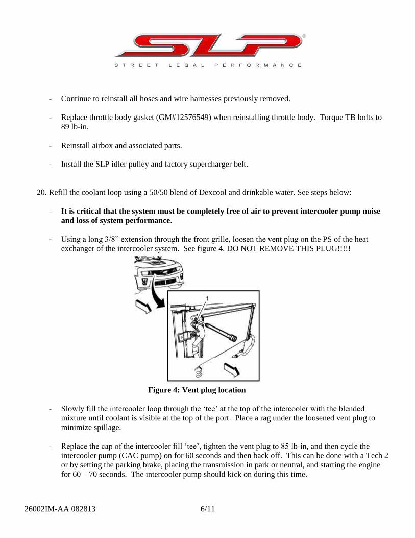
- Using a long 3/8” extension through the front grille, loosen the vent plug on the PS of the heat
exchanger of the intercooler system. See figure 4. DO NOT REMOVE THIS PLUG!!!!!
Figure 4: Vent plug location
- Slowly fill the intercooler loop through the ‘tee’ at the top of the intercooler with the blended
mixture until coolant is visible at the top of the port. Place a rag under the loosened vent plug to
minimize spillage.
- Replace the cap of the intercooler fill ‘tee’, tighten the vent plug to 85 lb-in, and then cycle the
intercooler pump (CAC pump) on for 60 seconds and then back off. This can be done with a Tech 2
or by setting the parking brake, placing the transmission in park or neutral, and starting the engine
for 60 – 70 seconds. The intercooler pump should kick on during this time.

26002IM-AA 082813 7/11
- Repeat this process of bleeding air through the vent plug and filling through the ‘tee’ until no more
coolant can be added to the system through the top of the ‘tee’.
21. Re-orient the ‘tee’ so the engine covers can be placed back on.
22. Install the provided SLP supercharger idler pulley in place of the factory idler and re-use the factory
supercharger belt. BE SURE TO USE BLUE LOC-TITE ON THE IDLER THREADS.
Header Installation Instructions
1. Disconnect the negative battery cable first, then the positive battery cable.
2. Raise and support the vehicle. A vehicle lift is highly recommended for this installation.
3. With the aid of a jack-stand, loosen the clamps holding the factory H-pipe to the CATS. Remove the
exhaust assembly from the vehicle. Some WD-40 sprayed on the rubber isolators will make this easier.
Remove the small cross-member underneath the vehicle. Remove the plastic splash shield underneath
the vehicle.
4. Unplug all four (4) oxygen sensors from the vehicle’s wire harness, remove them and set them aside so
they do not get damaged during the installation. Label the front and rear sensors for reinstallation later.
5. Lower the car, and remove all spark plug wires from both the coils and the spark plugs.
6. Remove the oil dipstick tube by unbolting it from the engine (make sure dipstick is removed first), then
pull it gently upward until it comes out.
7. Remove all eight (8) spark plugs from the engine.
8. Remove the passenger and driver’s side stock exhaust manifold (Figure 1). Removing the bolt closest to
the rear of the engine last will ease in removal. The manifold will come out from the bottom very easily.

26002IM-AA 082813 8/11
Figure 1: Passenger side manifold removed
9. Raise the car back up again, and cut off the end of the stud sticking out on the PS where the header will
sit (leave the nut on) to allow additional clearance. See Figure 2.
Figure 2: Stud to be cut down
10. Raise the car back up again, and slide the SLP Headers along with the new gaskets up into place and
start a couple of bolts to hold them in place (the rear bolts are easiest to do first). Be sure the gaskets are
in the proper orientation (Figure 3).
*NOTE* Be sure to start all exhaust manifold bolts by hand.

26002IM-AA 082813 9/11
Figure 3: Insertion of driver’s side header
11. Once the headers are held in by a couple of bolts, lower the car again. Proceed to insert the remaining
manifold bolts.
12. Tighten the exhaust manifold bolts beginning with the center two bolts. Alternate from side-to-side, and
work toward the outside bolts.
13. Tighten the exhaust manifold bolts a first pass to 12 ft-lbs.
14. Tighten the bolts a final pass to 18 ft-lbs.
15. Reinsert the dipstick tube back into the block from the top. It goes in between the center two header
tubes. You will have to wiggle the tube around a bit to get it back in the hole.
16. Next reinstall the spark plugs and wires (The wires will ‘click’ once on the spark plug side, and twice on
the other).
17. Plug in the supplied O2 sensor extensions into the wire harness for both front oxygen sensors. Let them
hang down so you can access them later.
18. Raise the car once again.
19. Next, slide a 3” Torca clamp onto each race pipe, and insert onto the header. Do not tighten at this time.
Repeat for other side.
20. Now take your SLP cat-to-factory exhaust adaptors and slide Torca Clamps onto the inlet ends. Slide
them onto the race pipes with the O2 bungs facing inwards.

26002IM-AA 082813 10/11
21. Reinstall the factory exhaust system. Slide the factory clamps over the SLP adaptor pipes. Adjust
exhaust system where necessary before tightening.
22. Using some oxygen sensor safe anti-seize lubricant on the threads of the oxygen sensors (Permatex High
Performance Anti-Seize Lubricant works well), thread the front and rear O2 sensors into their respective
bungs. Connect the four sensors to their respective harnesses and make sure the wires are clear of the
exhaust. Use wire ties to hold them away if necessary.
23. Hold up the splash guard and trim away the areas where it contacts the headers and cut to match the
shape of the frame. Install the cut splash guard. See Figure 4 below.
Figure 4: Trim away splash guard along frame as shown by dotted lines above
24. Lower the vehicle, and reconnect the negative battery terminal first, then the positive.
25. Start the vehicle and inspect for leaks.
26. Double check all fasteners and clearances after test driving. Adjust as necessary.

26002IM-AA 082813 11/11
Thermostat Installation Instructions
1. Remove the coolant pressure cap from the radiator.
2. Raise and support the vehicle.
3. If equipped with LSA/ZL1 package, remove the splash guard underneath the vehicle.
4. Place a clean drain pan under the radiator drain cock.
5. Loosen the radiator drain cock.
6. Drain the cooling system.
7. Lower the vehicle.
8. Tighten the radiator drain cock.
9. If equipped with LSA/ZL1 package, install the front compartment air deflector.
10. Lower the vehicle.
11. Remove the radiator outlet hose.
12. Remove the two bolts holding the thermostat in.
13. Remove the factory thermostat and replace with SLP low temperature thermostat.
14. Reinstall bolts and radiator hose.
Filling the coolant:
1. Slowly fill the radiator with a 50/50 coolant mixture until the coolant level is just below the radiator fill
neck.
2. Allow 30 seconds for the coolant level to stabilize and continue to fill the radiator until the level
stabilizes for at least 2 minutes.
3. Start the engine and allow to the engine to idle.
4. Slowly fill the coolant mixture until the level stabilizes at the just below the top of radiator fill neck for
at least 2 minutes.
5. Install the coolant pressure cap.
6. Allow the engine to idle until the engine reaches normal operating temperature.
7. Shut the engine OFF.
8. Allow the engine to cool.
9. Remove the coolant pressure cap and top off the engine coolant in the radiator.
10. Install coolant pressure cap.
11. Inspect and if necessary, fill the coolant reservoir bottle.

26002IM-AA 082813 12/11
12. Rinse away any excess coolant from the engine and the engine compartment. Inspect and top off as
necessary.