page 322d - gene slover's us navy pages home page€¦ · the gun carriage sustained by the...
TRANSCRIPT
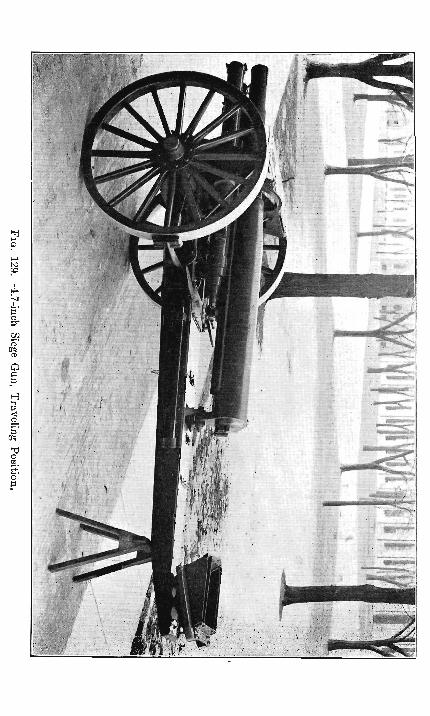
Page 322d Back of Fig. 129 Faces Page 323
ARTILLERY OF THE UNITED STATES LAND f.ERVWE. 323
eluded indicate that no practical advantage is gained by the use of wider tires on vehicles of this class and weight.
The trail is of the usual construction, two pressed steel flasks of channel section tied together by transoms and plates. The front ends of the flasks are riveted to cast steel axle bearings which extend to the front of the axle and support between them the pintle bearing p. The location of the pintle socket in front of the axle permits the use of a shorter trail and reduces the weight .at end of trail to be lifted in limbering.
Bearings are provided at about the middle of the trail, in the opening seen in Fig. 128, for a detachable geared drum which is used in giving initial compression to the counter recoil springs in assembling, and in withdrawing the gun to -its traveling position. When not in use the drum is kept in the tool-box in the trail.
The spade with its horizontal floats is hinged to , the trail on top. For traveling it is turned up and rests on top of the trail, see Fig. 129; for firing it is turned down. In either position it is locked in place by a heavy key bolt.
A bored lunette plate is riveted to the bottom of the trail, for engagement on the pintle of the limber.
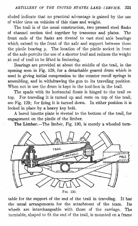
The Limber.-The limber, Fig. 130, is merely a wheeled turn-
FIG. 130.
table for the support of the end of the trail in traveling. It has the usual arrangements for the attachment of the team. Its wheels are interchangeable with those of the carriage. Th~
turntable, shaped to fit the end of the trail, is mounted on a frame
324 ORDNANCE AND GUNNERY.
fixed to the axle. It forms a seat. for the trail. The seat is pivoted at the rear end and its front end rests on · rollers which travel on a circular path on the limber. A pintle on the seat engages in the lunette in the bottom of the trail.
When traveling, in order to distribute the weight as evenly as possible between the front and rear wheels of the limbered carriage, the gun is disconnected from the piston rod and spring rods, and drawn back 40 inches to the rear, Fig. 129. In this position the recoil lug is secured between two stout braces attached to a heavy trail transom. The breech of the gun is thus supported and rigidly held in traveling, and the elevating and traversing mechanisms are relieved from all strains. The braces referred to are pivoted in the trail, and when not in use are turned down inside the trail.
189. Weights.-The weight of the gun carriage complete is 4440 lbs., and that of the gun and carriage, 7170 lbs. The weight at the end of the trail, gun in firing position, or the weight to be lifted in limbering, is 400 lbs.; with the gun in traveling position, this is increased to 1150 lbs., which is the part of the weight of the gun carriage sustained by the limber.
Siege Limber Caisson.-For the transportation of ammunition for siege batteries there is provided a vehicle called the siege limber caisson. AB the name indicates, this vehicle is composed of two parts. Each part supports an ammunition chest arranged to carry 28 rounds of 4.7-inch ammunition or 18 rounds of 6-inch ammunition, thus making 56 rounds of 4.7-inch ammunition or 36 rounds of 6-inch ammunition per vehicle. For each siege battery of 4 guns 16 limber caissons are provided.
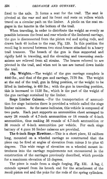
The 6-inch Siege Howitzer.-Thie is a short piece, 13 calibers long, mounted on a wheeled carriage so constructed that the piece cap be fired at angles of elevation from minus 5 to plus 45 degrees. This wide range of elevation on a wheeled mount introduces into the carriage requirements not encountered in the construction of the carriages previously described, which provide for a maximum elevation of 15 degrees.
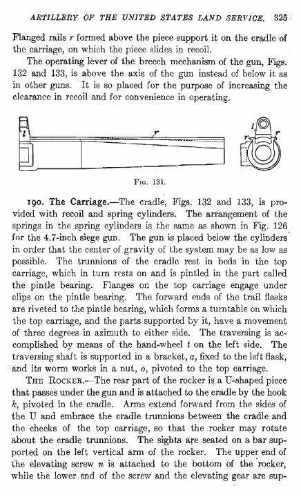
The piece is made from a single forging, Fig. 131. A lug, l, extends upward from its breech end for the attachment of the tecoil piston rod and the yoke for the rods of the spring cylinders.
ARTILLERY OF THE UNITED STATES LAND SERVl(JE. 325 ;
Flanged rails r formed above the piece support it on the cradle of the carriage, on which the piece slides in recoil.
The operating lever of the breech mechanism of the gun, Figs. 132 and 133, is above the axis of the gun instead of below it as in other guns. It is so placed for the purpose of increaSing the clearance in recoil and for convenience in operating.
FIG. 131.
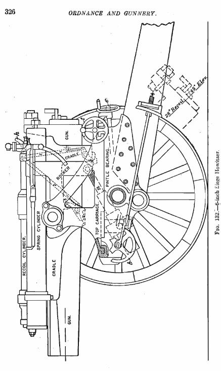
190. The Carriage.-The cradle, Figs. 132 and 133, is provided with recoil and spring cylinders. The arrangement of the springs in the spring cylinders is the same as shown in Fig. 126 for the 4.7-inch siege gun. The gun is placed below the cylinders' in order that the center of gravity of the system may be as low as possible. The trunnions of the cradle rest in beds in the top carriage, which in turn rests on and is pintled in the part called the pintle bearing. Flanges on the top carriage engage under clips on the pintle bearing. The forward ends of the trail flasks are riveted to the pintle bearing, which forms a turntable on which the top carriage, and the parts supported by it, have a movement of three degrees in azimuth to either side. The traversing is accompUshed by means of the hand-wheel t on the left side. The traversing shaft is supported in a bracket, a, fixed to the left flask,
·and its worm works in a nut, 0, pivoted to the top carriage. THE ROCKER.-The rear part of the rocker is a U-shaped piece
that passes under the gun and is attached to the cradle by the hook k, pivoted in the cradle. Arms extend forward from the sides of the U and embrace the cradle trunnions between the cradle and the cheeks of the top carriage, so that the rocker may rotate about the cradle trunnions. The sights are seated on a bar supported on the left vertical arm of the rocker. The upper end of the elevating screw n is attached to the bottom of the' rocker, while the lower end of the screw and the elevating gear are sup-
326 ORDNANCE AND GUNNERY.
I~ I
ARTILLERY OF THE UNITED ST AXES LAND SERVICE. 327
ported by trunnions in lugs on the under side of the top car~ riage. The rocker therefore moves in elevation in the top carriage and gives elevation to the gun-supporting cradle fastened to the rocker by the hook k. The elevating apparatus is operated by a hand-wheel e on either side.
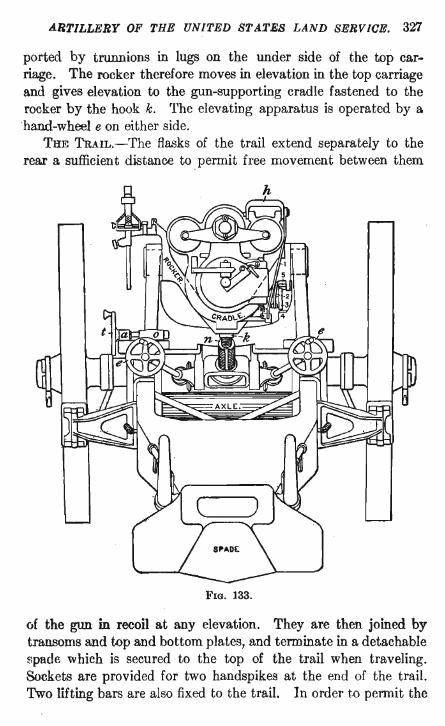
THE TRAIL.-The flasks of the trail extend separately to the rear a sufficient distance to permit free movement between them
FIG. 133.
of the gun in recoil at any elevation. They are then joined by transoms and top and bottom plates, and terminate in a detachable spade which is secured to the top of the trail when traveling. Sockets are provided for two handspikes at the end of the trail. Two lifting bars are also fixed to the trail. In order t.o permit the
328 ORDNANCE AND GUNNERY.
desired movement of the cradle in elevation the axle is in three parts, the middle part lower than the two axle arms. The three parts are held by shrinkage in cylinders formed in the sides of the pintle bearing.
The wheel brakes, used both in firing and in traveling, are manipulated by hand-wheels b in front of the axle.
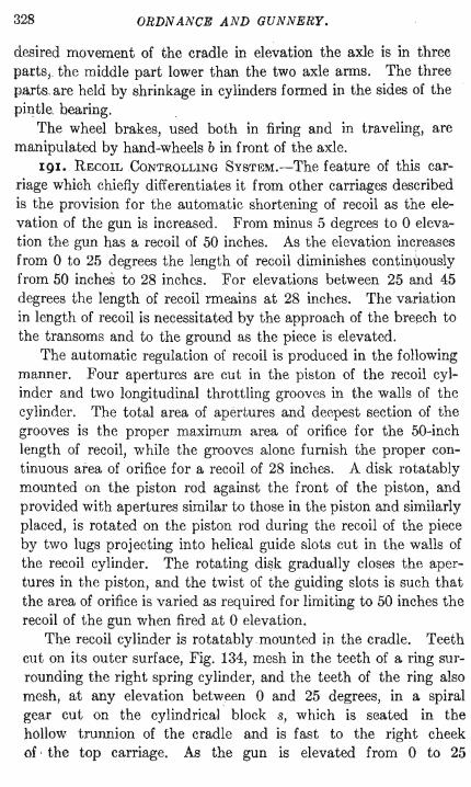
191. RECOlLCONTROLLING SysTEM.-The feature of this carriage which chiefly differentiates it from other carriages described is the provision for the automatic shortening of recoil as the elevation of the gun is increased. From minus 5 degrees to 0 elevation the gun has a recoil of 50 inches. As the elevation increases from 0 to 25 degrees the length of recoil diminishes continvously from 50 inches to 28 inches. For elevations between 25 and 45 degrees the length of recoil rmeains at 28 inches. The variation in length of recoil is necessitated by the approach of the breech to the transoms and to the ground as the piece is elevated.
The automatic regulation of recoil is produced in the following manner. Four apertures are cut in the piston of the recoil cylinder and two longitudinal throttling grooves in the walls of the cylinder. The total area of apertures and deepest section of the grooves is the proper maximum area of orifice for the 50-inch length of recoil, while the grooves alone furnish the proper continuous area of orifice for a recoil of 28 inches. A disk rotatably mounted on the piston rod against the front of the piston, and provided with apertures similar to those in the piston and similarly placed, is rotated on the piston rod during the recoil of the piece by two lugs projecting into helical guide slots cut in the walls of the recoil cylinder. The rotating disk gradually closes the apertures in the piston, and the twist of the guiding slots is such that the area of orifice is varied as required for limiting to 50 inches the recoil of the gun when fired at 0 elevation.
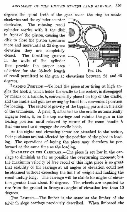
The recoil cylinder is rotatablymounted in the cradle. Teeth cut on its outer surface, Fig. 134, mesh in the teeth of a ring surrounding the right spring cylinder, and the teeth of the ring also mesh, at any elevation between 0 and 25 degrees, in a spiral gear cut on the cylindrical block s, which is seated in the hollow trunnion of the cradle and is fast to the right cheek of, the top carriage. As the gun is elevated from 0 to 25
ARTILLERY OF THE UNITED STATES LAND SERVICE. 329
degrees the spiral teeth of the gear· cause the ring to rotate clockwise and the cylinder counter clockwise. The rotating recoil !J cylinder carries with it the disk. ~ in front of the piston, causing the ~ disk to close the piston apertures more and more until at 25 degrees elevation they are completely closed. The throttling grooves ~ in the walls of the cylinder then provide the proper area . of orifice for the 28-inch length FIG. 134.
of recoil permitted to the gun at elevations between 25 and 45 degrees.
LOADING POSITION.-To load the piece after firing at high angles the hook k, which holds the cradle to the rocker, is disengaged by means of a handle, h, conveniently placed on top of the cradle, . and the cradle and gun are swung by hand to a convenient position for loading. The center of gravity of the tipping parts is in the axis of the trunnions. A pawl, 3, attached to the cradle automatically engages teeth, 4, on the top carriage and retains the gun in the loading position until released by means of the same handle h that was used to disengage the cradle hook.
As the sights and elevating screw are attached to the rocker, their positions are not affected by the position of the piece in loading. The operations of laying the piece may therefore be performed at the same time as the loading.
STABILITY OF THE CARRIAGE.-The piece is set low in the carriage to diminish as far as possible the overturning moment; but the maximum velocity of free recoil of this light piece is so great that stability of the carriage at all angles of elevation could not be obtained without exceeding the limit of weight and making the recoil unduly long. The carriage will be stable for angles of elevation greater than about 10 degrees. The wheels are expected to rise from the ground in firings at angles of elevation less than 10 degrees.
THE LIMIJER.-The limber is the same as the limber of the 4.7-inch siege carriage previously described. When limbered the
330 ORDNANCE AND GUNNERr.
6900
FIG. 135.
~trP~~-l,\---':-----------"--1
i -:-I'
. FIG. 136.
weight is slightly less than the limit of 8000 pounds, considered as a maximum load for a siege team.
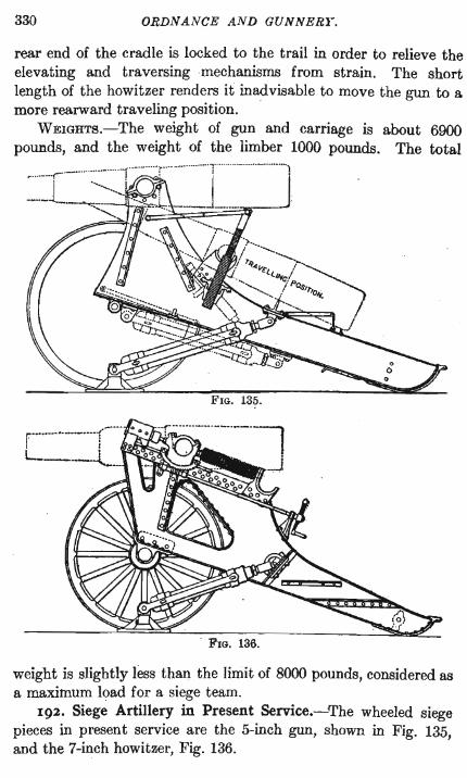
192. Siege Artillery in Present Service.-The wheeled siege pieces in present service are the 5-inch gun, shown in Fig. 135, and the 7-inch howitzer, Fig. 136.
ARTILLERY OF THE UNITED STATES LAND SERVICE. 331
When emplaced in a siege battery the carriage for either piece rests on a wooden platform. Recoil is limited by means of a hydraulic buffer attached to the trail and pintled in front to a heavy pintle fixed to the platform. The howitzer also recoils on the carriage, the recoil of the piece being controlled by hydraulic buffers one on each side in front of the trunnions. Springs, strung on rods in rear of the trunnions, return the gun to the firing posi~ tion. The springs are either coiled or Belleville springs, the latter being saucer shaped disks 01 steel strung face to face and back to back.
The pieces are mounted at a height of about six feet above the ground to enable the guns to be fired over a parapet of sufficient
. height to shelter the gunners. For traveling, the guns are shifted to the rear into trunnion.
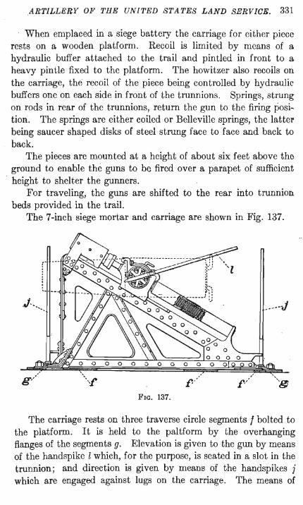
beds provided in the trail. The 7-inch siege mortar and carriage are shown in Fig. 137.
,. ~----
_----J
FIG. 137.
The carriage rests on three traverse circle segments f bolted to the platform. It is held to the paltform by the overhanging flanges of the segments g. Elevation is given to the gun by means of the handspike l which, for the purpose, is seated in a slot in the trunnion; and direction is given by means of the handspikes j which are engaged against lugs on the carriage. The means of
332 ORlJN ANCE AND GUNNERY.
controlling the recoil of the piece are similar to those employed with the 7-inchhowitzer.
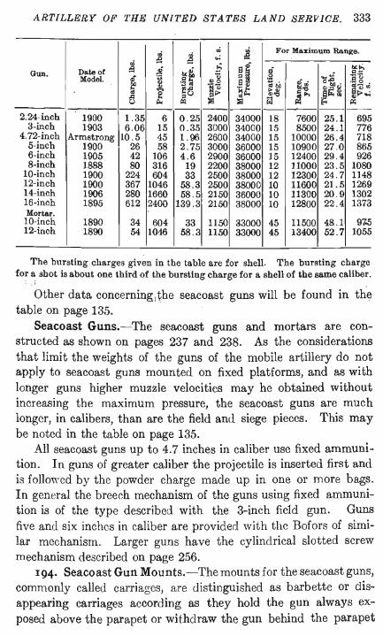
193. Seacoast Artillery.-Comprised in the seacoast artillery are guns . ranging in caliber from 2.24 inches to 16 inches, their projectiles ranging in weight from 6 pounds to 2400. The 2.24-inch and 3-inch guns, called the 6-pounder and the 15-pounder, are used for the defense of the sea fronts of fortifications against landing parties and for the defense of the submarine mine fields. The guns ·of medium caliber, from 4 to 6 inches, are best used for the protection of places subject to naval raids, and for the defense of mine fields at distant ranges. Their fire is effective against unarmored or thinly armored ships.
The 8- and lO-inch guns are effective against armored cruisers and against the thinly armored parts of battleships.
The proper target for guns 12 inches or more in caliber is the heavy water line armor of the enemy's battleship.
The 12-inch gun is the largest gun at present mounted in our fortifications. One 16-inch gun has been manufactured and satisfactorily tested, but no guns of this caliber are mounted. The latest model of 12-inch gun was designed to give the 1000 pound projectile a muzzle velocity of 2550 feet, which would insure perforation, at a range of 8700 yards, of the 12-inch armor carried by the latest type of battleship. But it has been found that in the production of this high muzzle velocity in a heavy projectile the erosion due to the heat and great volume of the powder gases is so great as to materially shorten the life of the gun. It has been decided therefore as a measure of economy to reduce the muzzle velocities of the larger guns from 2550 feet to 2250, and to build for the defense of such wide waterways as cannot be properly defended by the 12-inch guns with the reduced velocity, 14-inch guns which will give to a 1660-pound projectile a muzzle velocity of 2150 feet, sufficient to insure perforation of 12-inch armor at a range of 8700 yards.
The wide channels that exist at the entrances to Long Island Sound, Chesapeake Bay, Puget Sound, and Manila Bay will require these 14-inch guns for their defense.
The table following contains data relating to seacoast guns. . :i·
ARTILLERY OF THE UNITED STATES LAND SERVICE. 333
.; ~
.; ~ For Maximum Range .
:9 ... Date of ~ .i b<~ ~ 8~ ~- .
1><1>, Gun.
,,~
Model.
~ OJ ~g :0$ .....s -c:; ~~ 8., <li ' ef. . '~.s .
'" ~~ ~<l "14'" "'bll "," "';::;~ 8"''' 2 ,.'" ,,'" .Q :01> ","- ~ ... ~ ... ~~., .,~ ... Q "- cq )ill )ill '" ... ---------- ---------------
2. 24-inch 1900 1.35 6 0 .25 2400 340QO 18 7600 25.1 695 3-inch 1903 6.06 15 0.35 3000 34000 15 8500 24.1 776
4. 72-inch Armstrong 10.5 45 1.96 2600 34000 15 10000 26.4 718 5-inch 1900 26 58 2 .75 3000 36000 15 10900 27.0 865 6-inch 1905 42 106 4.6 2900 36000 15 12400 29.4 926 8-inch 1888 80 316 19 2200 38000 12 11000 23.5 1080
lO-inch 1900 224 604 33 2500 38000 12 12300 24.7 1148 12-inch 1900 367 1046 58.3 2500 38000 10 11600 21.5 1269 14-inch 1906 280 1660 58 .5 2150 36000 10 11300 20.9 1302 16-inch 1895 612 2400 139 .3 2150 38000 10 12800 22.4 1373 Mortar.
lO-inch 1890 34 604 33 1150 33000 45 11500 48 .1 97..5 12-inch 1890 54 1016 58 .3 1150 33000 45 13400 52 .7 1055
The bursting charges given in the table are for shell. The bursting charge for a shot is about one third of the bursting charge for a shell of the same caliber.
Other data concerning l ~he seacoast guns will be found in thl;} table on page 135.
Seacoast Guns.-The seacoast guns and mortars are constructed as shown on pages 237 and 238. As the considerations that limit the weights of the guns of the mobile artillery do not apply to seacoast guns mounted on fixed platforms, and as with longer guns higher muzzle velocities may he obtained without increasing the maximum pressure, the seacoast guns are much longer, in calibers, than are the field and siege pieces. This may be noted in the table on page 135.
All seacoast guns up to 4.7 inches in caliber use fixed ammunition. In guns of greater caliber the projectile is inserted first and is follovved by the powder charge made up in one or more bags. In general the breech mechanism of the guns using fixed ammunition is of the type described with the 3-inch fie1d gun. Guns five and six inches in caliber are provided with the Bofors of similar mechanism. Larger guns have the cylindrical slotted screw mechanism described on page 256.
194. Seacoast Gun Mounts.-The mounts for the seacoast guns, commonly called carriages, are distinguished as barbette or disappearing carriages according as they hold the gun always exposed above the parapet or withdraw the gun behind the parapet
334 ORDN ANCE AND GUNNERY.
at each round fired. The disappearing carriage has the advantage of excellent protection for the carriage and gun crew, and, for guns of the larger calibers, the added advantage of greatly increased rapidity of fire. The increased rapidity of fire is due to the lowering of the gun to a height convenient for loading, so that the heavy projectiles and charg~s of powder need not be lifted in loading. On high sites the disappearing carriage is not necessary to secure protection for the gunners, for behind the parapets the gunners can only be reached by high angle fire from the enemy's ship, and on account of the excessive strain on the decks that would accompany such fire guns aboard ship are not so mounted that they can be fired at high angles. Disappearing carriages, emplaced, are more costly than barbette carriages, but the advantage of the more rapid fire from the disappearing carriage has determined its use in this country for all seacoast guns above six inches in callber, on high .sites as well as on low sites.
Many of the &-inch guns and all guns below six inches in caliber are mounted on barbette carriages provided with shields of armor plate for the protection of the gunners .
. Seacoast guns being permanently emplaced the weights of the gun and the carriage, and simplicity of mechanism in both gun and carriage, are not matters of such importance as they are in the field and siege artillery. We consequently find adapted to the seacoast guns and carriages every mechanism that will assist in increasing the rapidity of fire. Fixed ammunition is used in guns up to 4.7 inches in caliber and its use will probably be extended to larger calibers. Experiments are being made with mechanisms for the automatic or semi-automatic opening and closing of the breech. The mechanisms for elevating the gun and for traversing the carriage are arranged to be operated from either side of tl1e carriage, and in the carriages for the larger guns provision is made forthe operation of these mechanisms both by hand and by electric power. Sights are provided on both sides of the gun, and the operations of aiming and loading may proceed together.
Finally the magazines and shell rooms in the walls of the fortifications are so arranged with regard to the gun emplacement, and so equipped, as to insure a rapid delivery of ammunition to every gun.
ARTILLERY OF THE UNITED STATES LAND SERVICE. 335
The seacoast gun mounts differ for guns of different caliber. A description of one mount of each distinct type will follow and will serve to show the principles that govern in similar constructions.
GENERAL CHARACTERISTlcs.-In general, the mount consists of a fixed base bolted to the concrete platform of the emplacement, and of a gun-supporting superstructure resting on the base and capable of revolution about some part of it. The superstructure supports, in addition to the gun, all the recoil controlling parts and the necessary mechanisms for elevating, traversing, and retracting the gun.
Fastened to the fixed base or to the platform around the base is an azimuth circle graduated to half degrees, and on the movable part of the carriage is fixed a pointer, with vernier reading to minutes, that indicates the azimuth angle made by the gun with a meridian plane through its center of motion.
The gun, supported by means of its trunnions on the superstructure of the carriage or contained in a cradle which is itself so .. supported, has movement in elevation about the axis of the trunnions. The elevating mechanisms, or the sights, are provided ", ith graduated scales which usually indicate the range corresponding to each position of the gun . .
Protecting guards are provided wherever necessary for the protection of the gunners against accident, or for the protection of the mechanisms of the carriage against the entrance of dust or water.
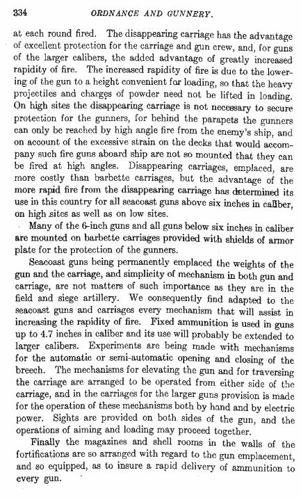
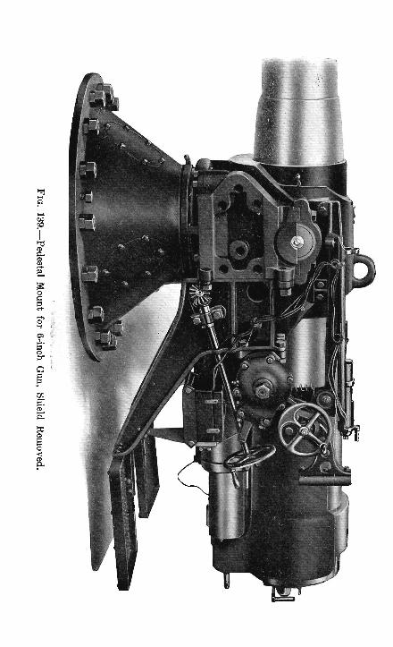
195. Pedestal Mounts.-Seacoast guns up to six inches in caliber are mounted in barbette on carriages similar in construction to the carriage shown in Figs. 138 and 139.
A conical pedestal of cast steel, p Fig. 138, is bolted to the concrete platform. A pivot yoke y free to revolve is seated in the pedestal. In the upwardly extending arms of the pivot yoke are seats for the trunnions . of the cradle c. The gun is supported and slides in recoil in the cradle. The weight of all the revolving parts is supported by a roller bearing r on a central boss in the base of the pedestal. In the lower rear portion of the cradle are formed a central recoil cylinder and two spring cylinders, Fig. 139, similar to the corresponding cyJ-
336 ORDN ANCE AND GUNNERY.
inders described in the 4.7-inch siege carriage, but much shorter. AB the seacoast gun mounts are firmly bolted to pli1tforms and as
they may be made as strong as desired without limit as to weight, these mounts will stand much higher stresses, without movement or rupture, than can be imposed on a wheeled carriage. We therefore find that shorter recoil is allowed to the seacoast guns than to the lighter field and siege guns. Thus the recoil of the 5-inch gun on the pedestal
FIG. 138. mount is but 13 inches, and of the 6-inch gun 15 inches,
while the 4.7-inch siege gun recoils 66 inches on its carriage and the 3-inch field gun 45 inches. .
Bolted to the arms of the pivot yoke, on each side, are brackets to which are attached platforms for the gunners. The platforms move with the gun in azimuth and carry the gunners undisturbed in the operations of pointing and of manipulating the breech mechanism.
The carriage may be traversed from either side. The shafts of the traversing hand-wheels extend downward toward the pedestal and actuate a horizontal shaft held in bearings on the pivot yoke. A worm on this shaft acts on a circular worm-wheel surrounding the top of the pedestal, t Fig. 138.
Elevation is given by the upper hand-wheel, on the left side only. The elevating gear is supported by a bracket bolted to the platform bracket and works on an elevating rack attached to the cradle, the center of the rack being in the axis of the trunnions ..
The traversing rack, or worm-wheel, surrounding the upper part of the pedestal is held to the pedestal by an adjustable friction band; and a worm-wheel in the elevating gear, contained in the gear casing fixed to the elevating bracket, Fig. 139, is held between two adjustable friction disks. These friction devices are so adjusted as to enable the gun to be traversed or elevated without
Page 336b Back of Fig. 139 Faces Page 337
ARTILLERY OF THE UNiTED STATES LAND SERVICE . 337
slipping oUhe mechanism, and yet to permit slipping in case undue strain is brought on the teeth of the worm-wheels.
A shoulder guard is attached to the cradle on each side of the gun to protect the gunners from injury during movement of the piece in recoil.
Open sights and a telescopic sight are seated in brackets on the cradle on each side of the gun. Dry batteries in two boxes held in brackets secured to the platform brackets supply electric power for firing the piece and for lighting the electric lamps of the sights.
The shield, of hardened armor plate, 41 inches thick; is fastened by two spring supports to the sides of the pivot yoke. The bolt holes for the shield support are seen in Fig. 139. The shield is pierced with a port for the gun and with two sight holes, and is inclined at an angle of 40 degrees with the horizon, see Fig. 201.
196. The Balanced Pillar Mount.-A variation of the mount just described is found in the balanced pillar mount, also called the masking parapet mount. This mount is constructed for guns . up to 5 inches in caliber. The purpose of this mount is to afford a means of withdrawing the gun, when not in use, behind the parapet and out of the view of the enemy. The gun is withdrawn behind the parapet only after the firing is completed, and not after each round. Guns mounted on the disappearing carriages later described are withdrawn from view after each round fired.
The construction of the balanced pillar mount will be understood from Fig. 140. The pintle yoke, with all the parts supported by it, rests on the top of a long steel cylinder which has movement up and down in an outer cylinder. The base · of the pintle yoke is circular. It embraces a heavy pintle formed on the top of the cylinder and rests on conical rollers which move on a path provided on the cylinder top. Clips attached to the base of the pivot yoke engage under the flanges of the roller path and hold the top carriage to the cylinder.
Imbedded in the concrete of the platform is the outer cast iron cylinder in which the inner cylinder slides up and down. The weight of the inner cylinder and supported parts is balanced by lead and iron counterweights strung on a central rod which is connected to brackets on the inside of the inner cylinder by thr~e

ORDNASCE AlI"D GUNNERY.
chains. The pulleys over which the chains pass are supported on posts that pass through holes in the counterweight and rest in sockets formed in the bottom of the cylinder. For lifting and lowering the inner cylinder with the gun and top carriage, a ver-
tical toothed rack is fixed to the exterior of the inner cylinder. A pinion is seated in bearings provided at the top of the outer cylinder and engages in the rack. The pinion is turned by means of two detachable levers mounted on the ends of the pinion shaft.
ARTILLERY OF THE UNITED S7;ATES LAND SERVICE. 339
By means of a friction clamp the pinion is made to hold the elevated carriage against any sudden downward shock.
The construction permits a vertical movement of the gun and carriage of about 3} feet.
When firing, the muzzle of the gun projects over the parapet ; and before lowering, the gun is turned ·parallel to the parapet.
In a similar mount provided for 3-inch guns the outer cylinder is a double cylinder. The counterweight is annular and occupies the space between the two cylinders composing the double outer cylinder. The lifting levers are applied directly to the shaft of one of the chain pulleys, over which pass the chains that connect the counterweight to brackets on the outside of the inner cylinder. The brackets move in slots provided in the interior of the double cylinder.
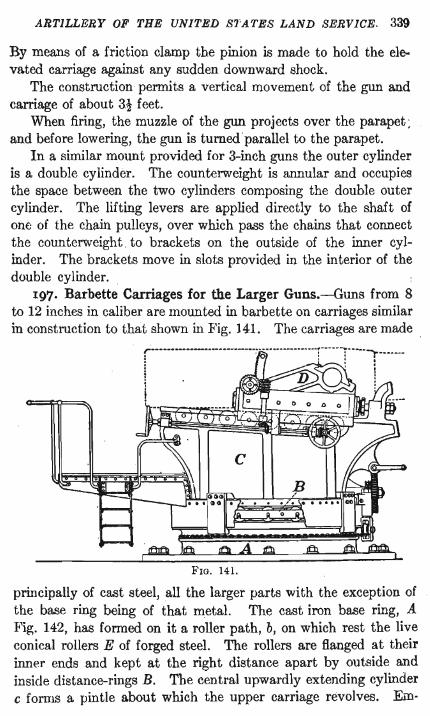
197. Barbette Carriages for the Larger Guns.-Guns from 8 to 12 inohes in caliber are mounted in barbette on carriages similar in construction to that shown in Fig. ) 41. The carriages are made .
r ... --·----... -.. -.. ---... -... -......... -... · ... ~-- .. -....... ----.. -... -... -r-... -.... -: ............ '"1--.......... .. : ' : . iii I i
FIG. 141.
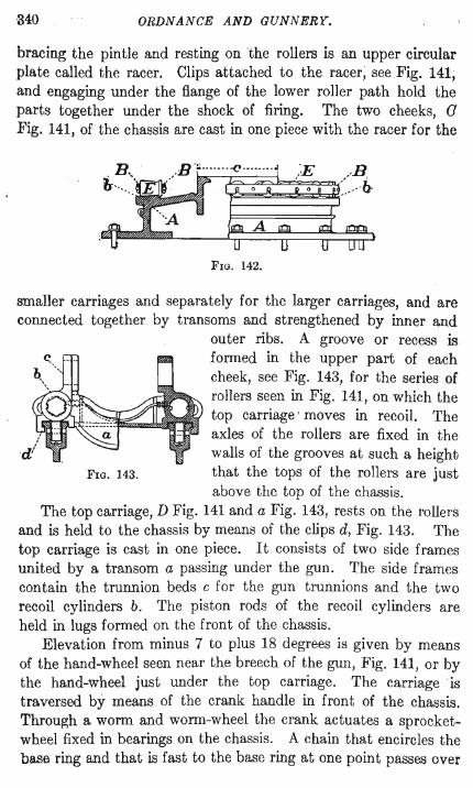
principally of cast steel, all the larger parts with the exception of the base ring being of that metal. The cast iron base ring, A :Fig. 142, has formed on it a roller path, b, on which rest the live conical rollers E of forged steel. The rollers are flanged at their inner ends and kept at the right distance apart by outside and inside distance-rings B. The central upwardly extending cylinder c forms a pintle about which the upper carriage revolves. Em-
340 ORDNANCE AND GUNNERY.
bracing the pintle and resting on the rollers is an upper circular plate called the racer. Clips attached to the racer, see Fig. 141; and engaging under the flange of the lower roller path hold the parts together under the shock of firing. The two cheeks, a Fig. 141, of the chassis are cast in one piece with the racer for the
IE /B, ~====~~:..-...~
FIG. 142.
smaller carriages and separately for the larger carriages, and are connected together by transoms and strengthened by inner and
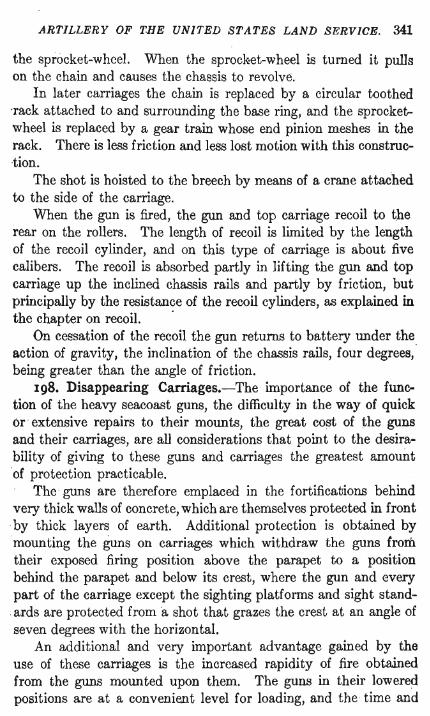
outer ribs. A groove or recess is formed in the upper part of each cheek, see Fig. 143, for the series of rollers seen in Fig. 141, on which the top carriage ' moves in recoil. The axles of the rollers are fixed in the walls of the grooves at such a height
FIG. 143. that the tops 6f the rollers are just above the . top of the chassis.
The top carriage, D Fig. 141 and a Fig. 143, rests on the rollers and is held to the chassis by means of the clips d, Fig. 143. The top carriage is cast in one piece. It consists of two side frames united by a transom a passing under the gun. The side frames contain the trunnion beds c for the gun trunnions and the two recoil cylinders b. The piston rods of the recoil cylinders are held in lugs formed on the front of the chassis.
Elevation from minus 7 to plus 18 degrees is given by means of the hand-wheel seen near the breech of the gun, Fig. 141, or by the hand-wheel just under the top carriage. The carriage is traversed by means of the crank handle in front of the chassis. Through a worm and worm-wheel the crank actuates a sprocketwheel fixed in bearings on the chassis. A chain that encircles the base ring and that is fast to the base ring at one point passes over
ARTILLERY OF THE UNITED STATES LAND SERVICE. 341
the sprocket-wheel. When the sproc~et-wheel is turned it pulls on the chain and causes the chassis to revolve.
In later carriages the chain is replaced by a circular toothed -rack attached to and surrounding the base ring, and the sprocketwheel is replaced by a gear train whose end pinion meshes in the rack. There is less friction and less lost motion with this construction.
The shot is hoisted to the breech by means of a crane attached to the side of the carriage.
When the gun is fired, the gun and top carriage recoil to the rear on the rollers. The length of recoil is limited by the length of the recoil cylinder, and on this type of carriage is about five calibers. The recoil is absorbed partly in lifting the gun and top carriage up the inclined chassis rails and partly by friction, but principally by the resistance of the recoil cylinders, as explained in the chapter on recoil. .
On cessation of the recoil the gun returns to battery 1lllder the action of gravity, the inclination of the chassis rails, four degrees, being greater than the angle of friction.
198. Disappearing Carriages.-The importance of the funce
tion of the heavy seacoast guns, the difficulty in the way of quick or · extensive repairs to their mounts, the great cost of the guns and their carriages, are all considerations that point to the desirae bility of giving to these guns and carriages the greatest amount ·of protection practicable.
The guns are therefore emplaced in the fortifications behind very thick walls of concrete, which are themselves protected in front . by thick layers of earth. Additional protection is obtained by mounting the guns on carriages which withdraw the guns from their exposed firing position above the parapet to a position behind the parapet and below its crest, where the gun and every part of the carriage except the sighting platforms and sight standards are protected from a shot that grazes the crest at an angle of seven degrees with the horizontal.
An additional and very important advantage gained by the use of these carriages is the increased rapidity of fire obtained from the guns mounted upon them. The guns in their lowered positions are at a convenient level for loading, and the time and
342 ORDNANCE AND GUNNERY.
labor that must be expended in lifting the heavy projectiles and powder charges to the breech of a gun of the same caliber mounted in barbette are practically elIminated.
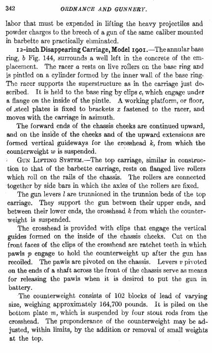
12-inch Disappearing Carriage, Model 190I.-Theannular bas(l ring, b Fig. 144, surrounds a well left in the concrete of the em, placement. The racer a rests on live rollers on the base ring and is pintled on a cylinder formed by the inner wall of the base ring. The racer supports the superstructure as in the carriage just de, scribed. It is held to the base ring by clips c, which engage under a flange on the inside of the pintle. A working platform, or floor, of .steel plates is fixed to brackets x fastened to the racer, and moves with the carriage in azimuth.
The forward ends of the chassis cheeks are continued upward, and on the inside of the cheeks and of the upward extensions are formed vertical guideways for the crosshead k, from which the counterweight w is suspended. .
GUN LIFTING SYSTEM.-The top carriage, similar in construction to that of the barbette carriage, rests on flanged live rollers which roll on the rails of the chassis. The rollers are connected 'together by side bars in which the axles of the rollers are fixed.
The gun levers l are trunnioned in the trunnion beds of the top carriage. They support the gun between their upper ends, and between their lower ends, the crosshead k from which the counterweight is suspended.
The crosshead is provided with clips that engage the vertical guides formed on the inside of the chassis cheeks. Cut on the front faces of the clips of the crosshead are ratchet teeth in which pawls p engage to hold the counterweight up after the gun has recoiled. The pawls are pivoted on the chassis. Levers v ph'oted on the ends of a shaft across the front of the chassis serve as means for releasing the pawls when it is desired to put the gun in battery.
The counterweight consists of 102 blocks of lead of varying size, weighing approximately 164,700 pounds. It is piled on the bottom plate m, which is suspended by four stout rods from the crosshead. The preponderance of the counterweight may be adjusted, within limits, by the addition or removal of small weights at the top.
-------
~ ~
~ ~
~ ~ tI;J
~ .... ~ 1::::1
l:t.l ""3 ;:...
~ ~ §
5 ~
C5 ~
~
344 ORDNANCE AND GUNNERY.
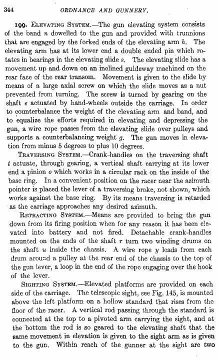
199. ELEVATING SYSTEM.-The gun elevating system consists of the band n dowelled to the gun and provided with trUIUlions that are engaged by the forked ends of the elevating arm h. The elevating arm has at its lower end a double ended pin which rotates in bearings in the elevating slide s. The elevating slide has a movement up and.down on an inclined guideway machined on the rear face of the rear transom. Movement is given to the slide by means of a large axial screw on which the slide moves as a nut prevented from turning. The screw is turned by gearing on the shaft e actuated by hand-wheels outside the carriage. In order to counterbalance the weight of the elevating arm and band, and to 'equalize the efforts required in elevating and depressing the gun, a wire rope passes from the elevating slide over pulleys and supports a counterbalancing weight g. The gun moves in elevation from minus 5 degrees to plus 10 degrees.
TRAVERSING SYSTEM.-Crank-handles on the traversing shaft t actuate, through gearing, a vertical shaft carrying at its lower end a pinion 0 which works in a circular rack on the inside of the base ring. In a convenient position on the racer near the azimuth pointer is placed the lever of a traversing brake, not shown, which works against the base ring. By its means traversing is retarded . as the carriage approaches any desired azimuth.
RETRACTING SYSTEM.-Means are provided to bring the gun down from its firing position when for any reason it has been elevated into battery and not fired. Detachable crank-handles mounted on the ends of the shaft r turn two winding drums on the shaft u inside the chassis. A wire rope y leads from each drum arou::J.d a pulley at the rear end of the chassis to the top of the gun iever, a loop in the end of the rope engaging over the hook of the lever.
SIGHTING SYSTEM.-Elevated platforms are provided on each side of the carriage. The telescopic sight, see Fig. 145, is mounted above the left platform on a hollow standard that rises from the floor of the racer. A vertical rod passing through the standard is connected at the top to a pivoted arm carrying the sight, and at the bottom the rod is so geared to the elevating shaft that the same movement in elevation is given to the sight arm as is given to the gun. Within reach of the . gunner at the sight are two
ITj p ...... >l'-?, I ...... t;" 5· 0 p-
O r:: ;; 0 ;;
t:1 Ui· P
'"0 '"0
'" p .., S·
(Jq
0 p .., .., p.
(Jq
.'" t"' 0 p
&. ;;
(Jq
'"t1 .'<f,; 0 f!J. :or. 0 p
Page 344b Back of Fig 145 Faces Page 345
ARTILLERY OF THE UNITED STATES LAND SERVICE. 345
crank-handles, at the upper ends of vertical shafts, by means of which the gunner has electric control of the elevating, traversing, and retracting mechanisms.
Trials are being made of the panoramic sight fitted to disappearing carriages. The vertical tube of the sight is made very long and the sight is attached to the side of the carriage in such a position that the eye piece is convenient to the gunner standing on the racer platform, while the head piece of the sight is above the parapet.
OPERATION.-The operation of the carriage for firing is as follows. The gun is loaded in its retracted position, Fig. 145, being held in that position by the pawls p engaged in the notches on the crosshead k. After the gun is loaded the tripping levers v are raised, releasing the pawls from the notches in the crosshead. The counterweight falls and the top carriage moves forward on its rollers, the last part of its motion being controlled by the counter-recoil buffers in the recoil cylinders, so that the top carriage comes to rest without shock on the chassis. By the movement of the gun levers the gun is lifted to its elevated position above the parapet.
When the piece is fired the movements are reversed in direction. The recoil forces the gun to the rear, the top carriage rolls back on the chassis rails and the counterweight rises vertically · under the restraint" of the guides engaged by the crosshead.
In the movement either way the upper end of the gun lever describes an · arc of an ellipse. The path of the muzzle of the gun, indicated in Fig. 144, is affected by the constraint of the elevating arm. The ellipse is the most favorable figure to follow in the movement of a gun on a disappearing carriage. From the firing position the movement of the gun is at first almost horizontally backward, and the movement downward occurs principally in the latter part of the path. Therefore the carriage that moves the gun in an elliptical pat.h can be brought nearer to the parapet and thus receive better protection than any other carriage.
The recoil is controlled principally by the recoil cylinders, and the shock at the cessation of motion is mitigated by two buffers f which receive the ends of the gun levers. The buffers are composed of steel plates alternating with sheets of balata.

346 ORDNANCE AND GUNNERY.
Balata is a substance that resembles hardened rubber. It has not as great elasticity as rubber but does not deteriorate as rapidly under exposure to the weather.
200. Modification of the Recoil System.-In the chapter on recoil it was pointed (jut that there is a disadvantage in having the control of the counter recoil in the same hydraulic cylinders that control the recoil. The adjustment of the counter-recoil system affects the adjustment of the recoil system.
It will also be observed in the carriage just described that in the latter part of the movement in recoil the glin is moving almost vertically downward. Consequently the movement of the top carriage to the rear is very slight during this part of the recoil, and the slight movement affords little opportunity for the close control by the recoil cylinders of the final movement of the gun. But it is in the last part of the recoil that complete control of the movement of the gun is most desirable, in order that the gun may be brought to rest at any desired position for loading, and without shock to the carriage.
:While the movement of the top carriage is least rapid at the latter end of recoil the counterweight has then its most rapid movement. Therefore a recoil cylinder fixed so as to move with the counterweight will afford the best control of the final movement of the gun.
The top carriage has its most rapid movement at the latter part of the movement of the gun into battery, while the counterweight has its least rapid movement at that time. The control of the counter recoil is therefore best effected through tl,e top carriage.
By retaining therefore, to act on the top carriage, recoil cylinders adapted for the control of the counter recoil only, and by adding to the counterweight a cylinder adapted for control of the recoil, we will obtain the advantage of completely separating the two systems, thus making them capable of independent adjustment, and the advantage of obtaining from each system the greatest control of the movement to which it is applied.
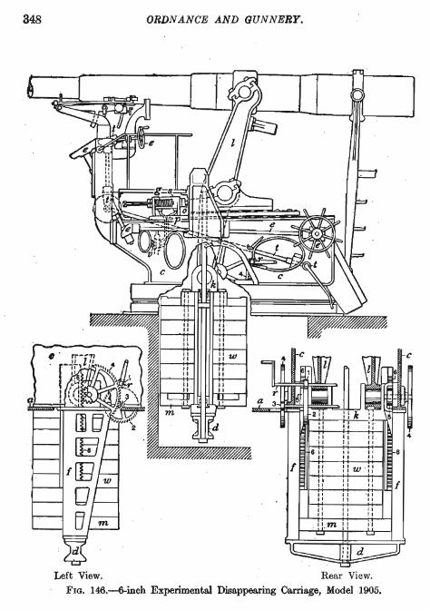
201. 6-inch Experimental Disappearing Carriage, Model 1905.-The modification of the recoil system as above indicated has been applied to a 6-inch. experimental carriage.
ARllLLERY OF THE UNITED STATES LAND SERVICE. 347
The recoil cylinder is held in the center of the counterweight, Fig. 146. The lower end of the piston rod is fixed in the lower member d of a frame whose sides f are bolted to the bottom of the racer a, as shown in the left and rear views. Grooves cut in the walls of the recoil cylinder permit the flow of the liquid from one side of the piston to the other. For the regulation of the extent of the recoil, and therefore of the height of the gun when in loading position, two diagonal channels pass through the center of the piston head from one face to the other, and the flow through them is controlled by a conical valve enclosed in the upper piston rod, which is hollow. The stem of the valve projects above the end of the piston rod.
The counter recoil is checked by the short cylinders s mounted on each chassis rail in front .of the top carriage. The pistons of the counter-recoil cylinders are not provided with apertures for the flow of the liquid from one side of the piston to the other, but the flow of the liquid takes place through the pipes p which are led from both cylinders to a valve v, by which the area of orifice is controlled and through which the pressure in the two cylinders is equalized. The pressure in the counter-recoil cylinders does not . exceed 500 pounds per square inch, while the pressure in the recoil cylinder is 1800 pounds.
As the top carriage comes into battery the front of the carriage strikes the rear end 0 of the piston rod and forces the piston through the cylinder against the liquid resistance and against the action of springs g mounted on each side of the cylinder. The springs act on central rods connected to the forward end of the piston, and as the top carriage moves from battery the springs move the piston to the rear in position to be acted on by the top carriage as it comes back into battery.
There are other points of difference between this carriage and the carriage last described.
The retraction of the gun from the firing position is accomplished without the use of wire ropes by the vertical racks 6, shown in the left and rear views, attached to bars that connect the crosshead k and the bottom section m of the counterweight. The end pinions 5 of two trains of gears, one on each side, mesh in the rack, the gear trains being actuated by the cranks on the shaft T. The
348 ORDNANCE AND GUNNERY.
Left View. Rear View. FIG. 146.-6-inch Experimental . Disappearing Carriage, Model 1905.
ARTILLERY OF THE ,UNITED STATES LAND SERVICE. 34~
retracting mechanism is partially shown in the smaller views. The parts are similarly numbered in all the figures. The mechanism is thrown out of gear when not in use.
The rollers of the top carriage are geared to the top carriage so that they are compelled to move with the top carriage and there can be no slipping of the top carriage on the rollers. In present Gervice carriages this slipping sometimes occurs as the gun recoils, so that on counter recoil the rollers reach their position in battery before the top carriage, and prevent the top carriage from coming fully into battery.
The sight standard is moved to the front of the chassis in order to get better protection for the gunner, for the sight, and for the elevating and traversing mechanisms under control of the gunner. Through the upper hand-wheel e and the shafts and gears also marked e the gunner has control of the elevating mechanism; and through another hand-wheel at his right hand, covered by the wheel e in the figure, and the shafts and gears marked t he controls the traversing mechanism.
Firings from this 6-inch carriage have shown that the gunner on the sighting platform is so near the muzzle of the gun that he is injuriously affected by the blast. The sighting platforms will therefore be removed to the rear end of the carriage, in which position they will also afford means of access to the breech when the gun is up.
202. Seacoast Mortars.-The thick armored sides of ships of war protect the ships to a greater or less extent against the direct fire from high powered guns. The great weight of armor that would be required for complete deck protection is prohibitive. The decks of war ships are therefore thin and practically unarmored, the heaviest protective deck on any battleship being not more than two inches thick over the flat part. The decks therefore offer an attractive target.
As the elevation above sea level of the sites of the guns in most fortifications is not sufficient to permit direct fire agaillst the decks, there are provided for use against this target the 12-inch seacoast mortars, short guns so mounted that they can be fired at high angles only. The heavy projectiles fired from these guns carry large bursting charges of high explosive. Descending
350 ORDNANCE AND GUNNERY.
almost vertically on the deck of a ship they easily overcome the slight resistance offered, and penetrating to the interior of the ship burst there with enormous destructive effect.
The mortar carriages permit firing only at angles of elevation between 45 and 70 degrees. With a fixed charge of powder a limited range only would be covered by fire between these angles. ,Charges of several different weights are therefore used in the mortars. With each charge a certain zone in range may be covered by the fire, and the charges are so fixed that the range zones overlap. Any point within the limits of range may thus be reached by the projectile. The least range with the smallest charge provided is about a mile and a half. Mortar batteries are therefore uSllally erected at not less than this distance from the channels or anchorages that are under their protection.
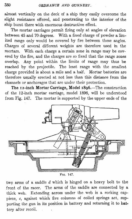
The I2-inch Mortar Carriage, Model 1896.-The construction of the 12-inch mortar carriage, model 1896, will be understood from Fig. 147. The mortar is supported by the upper ends of the
FIG. 147.
tW9 arms of a saddle d which is hinged on a heavy bolt to the front of the racer. The arms of the saddle are connected by a thick web. Extending across under the web is a rocking cappiece, c, against which five columns of coiled springs act, supporting the gun in its position in battery and returning it to bat. tery after recoil.
ARTILLERY OF THE UNITED STATES LAND SERVICE. 351
The lower ends of the springs rest in an iron box trunnioned in two brackets bolted to the bottom of the racer. The box oscillates as required during the movement of the saddle in recoil and counter recoil. Holes in the bottom of the box and in the cappiece and saddle web permit the ends of the rods on which the springs are strung to pass through during the movement . .
The recoil cylinders hare trunnioned in bearings fixed to the top of the racer. Bolted to the top of each cylinder is a frame f which serves as a guide for the crosshead 0 at the upper end of the piston rrJd. The crosshead embraces the stout pin r which extends C'utward from the trunnion of the mortar and communicates the motion of the piece in recoil to the piston rod.
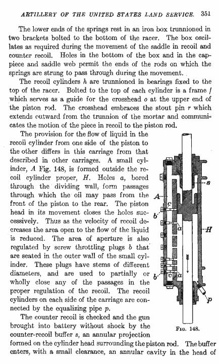
The provision for the flow of liquid in the recoil cylinder from one side of the piston to the other differs in this carriage from that described in other carriages. A small cylinder, A Fig. 148, is formed outside the recoil cylinder proper, H. Holes a, bored through the dividing wall, form passages through which the· oil may pass from the front of the piston to the rear. The piston head in its movement closes the holes successively. Thus as the velocity of recoil decreases the area open to the flow of t.he liquid is reduced. The area of aperture is also regulated by screw throttling plugs b that· are seated in the outer wall of the small cylinder. These plugs have stems of different diameters, and are used to partially or wholly close any of the passages in the proper regulation of the recoil. The recoil cylinders on each side of the carriage are connected by the equalizing pipe p.
The counter recoil is checked and the gun brought into battery without shock by the counter-recoil buffer s, an annular projection
FIG. 148.
formed on the cylinder head surrounding the piston rod. The buffer enters, with a small clearance, an annular cavity in the head of
352 ORDNANCE AND GUNNERY.
the piston, and the liquid in the cavity escapes slowly through the clearance. As an added precaution against shock when the gun returns to battery, buffer stops composed of alternate layers of balata and steel plates are held between the crosshead guides of the frame I, Fig. 147, under the cap.
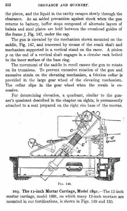
The gun is elevated by the mechanism shown mounted on the saddle, Fig. 147, and traversed by means of the crank shaft and mechanism supported in a vertical stand on the racer. A pinion pon the end of a vertical shaft engages in a circular rack bolted to the inner surface of the base ring.
The movement of the saddle in recoil causes the gun to rotate on its trunnions. To prevent excessive rotation of the gun and excessive strain on the elevating mechanism, a friction collar is provided in the large gear wheel of the elevating mechanism. The collar slips in the' gear wheel when the strain is excessive.
For determining elevation, a quadrant, similar to the gunner's quadrant described in the chapter on sights, is permanently attached to a seat prepared on the right rim base of t~e mortar.
FIG. 149.
203. The 12-inch MortarCarriage, Model 189I.-The 12-inch mortar carriage, model 1891, on which many 12-inch mortars are mounted in our fortifications, is shown in Figs. 149 and 150.
ARTILLERY OF THE UNITED STATES LAND SERVICE. 353
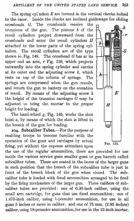
The spring cyrnders E are formed in the vertical cheeks bolted to the racer. Inside the cheeks are inclined guideways for sliding crossheads G. The crossheads receive the trurmions of the gun. The pistons h of t.he recoil cylinders project downward from the crossheads and enter the recoil cylinders H attached to the lower parts of the spring cylinders. The recoil cylinders are of the type shown in.Fig. 148. The crosshead G has at its upper end an arm, r Fig. 150, which projects outwardly into the spring cylinder and carries at its outer end the adjusting screw k, which rests on top of the column of springs. The springs are compressed when the gun recoils, and return the gun to battery on the cessation of recoil. By means of the adjusting screw k the height of the trunnion carriages G may be adjusted to bring the mortar to the proper height for loading.
The hand-wheel g, Fig. 149, works the shot hoist a, by means of which the shot is lifted to the breech of the gun for loading.
204. Subcaliber Tubes.-For the purpose of enabling troops to become familiar with the operation of the guns and carriages by actual firing, yet without the expense attendant upon
E
H
FIG. 150.
the use of the regular ammunition, there are provided for use inside the various service guns smaller guns or gun barrels called subcaliber tubes. These are seated in the bores of the larger guns in such position that the breech of the subcaliber tube is just in front of the breech block of the gun when closed. The subcaliber tube is loaded with fixed ammunition arranged to be fired by the firing mechanism of the larger gun. Three calibers of sub- . caliber tubes are provided: one of 0.30-inch caliber, using the small arm cartridge, for guns that use fixed ammunition; one of 1.475-inch caliber, using I-pounder ammunition, for use in all guns 5 inches or more in caliber; and one of 75 mm. (2.95 inches) caliber, using I8-pounder ammunition, for use in the I2-inch mortar.
354 ORDNANCE AND GUNNERY .
. For those guns that use fixed ammunition the 3D-caliber subcalwer tube, a 30-caliber rifle barrel, is fixed in a metal mounting that has the shape and dimensions of the complete cartridge used in the piece. Fig. 151 shows the subcaliber tube for the 3-inch rifle.
FIG. 151.
The 30-caliber small arm cartridge is inserted in the barrel b anq is fired by the percussion firing mechanism of the piece. It is ~xtracted, far enough to be grasped by the hand, by the extrahor, two 'bowed springs 8 which are under compression when the: small arm cartridge is forced to its seat by the breech block ~f the gun. A special primer is used in the small arm cartridge, Iltrong enough to withstand without puncture the heavy blow of the firing pin of the gun.
The head of the subcaliber cartridge is permitted longitudinal movement in the body in order to allow for expansion of the 30-caliber barrel in firing.
FIG. 152.
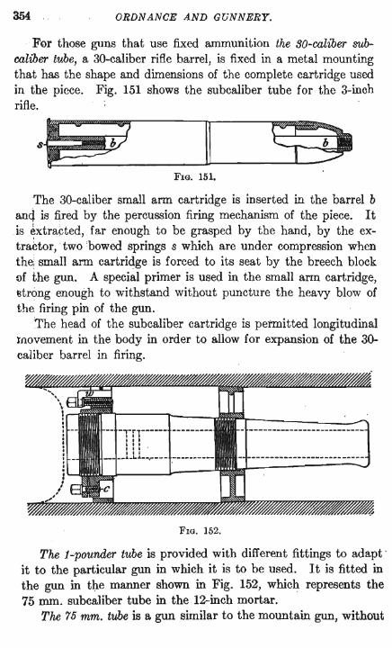
The 1-pounder tube is provided with different fittings to adapt· it to the particular gun in which it is to be used. It is fitted in the gun in the manner shown in Fig. 152, which represents the 75 mm. subcaliber tube in the 12-inch mortar.
The 75 mm. tube is a gun similar to the mountain gun, without
ARTILLERY OF THE UNITED STATES LAND SERVICE. 355
its breech mechanism. The cartridges for the mountain gun are used in it.
The wheel-shaped fittings, called adapters, are screwed on the gun. The front adapter fits against the centering slope in the bore for the band of the projectile. The outer rim of the rear adapter is cut through at the top and the rim is expanded against the sides of the bore by the wedge w, w\lich is forced between the parts of the rim by means of the screw seated in one of them. The tube is prevented from turning in the adapters by the clamp screw c.
The firing mechanism of the guns in which the two larger subcaliLer tubes are used is not of the percussion type. . The cannoll cartridges used in these two tubes are therefore provided with the 110-grain igniting primer, described in the chapter on primers, in place of the usual percussion primer. The igniting primer in the cartridge is ignited by the flame from the ordinary primer seated in the rear end of the breech mechanism of the gun.
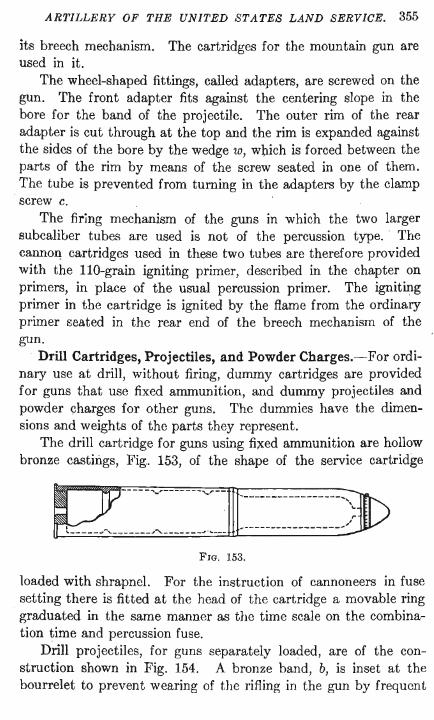
Drill Cartridges, Projectiles, and Powder Charges.-For ordinary use at drill, without firing, dummy cartridges are provided for guns that use fixed ammunition, and dummy projectiles and powder charges for other guns. The dummies have the dimensions and weights of the parts they represent.
The drill cartridge for guns using fixed ammunition are hollow bronze castings, Fig.. 153, of the shape of the service cartridge
[2:- hV_
m
y-~ JID . ' ... _---------------- ... '\'"
,. I ' ~-----------------~/ ,==,,= __ h'~ ______ ~. __
FIG. 153.
loaded with shrapnel. For the instruction of cannoneers in fuse setting there is fitted at the head of the cartridge a movable ring graduated in the same manner as the timc scale on the combination time and percussion fuse.
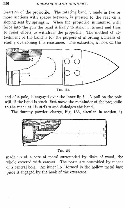
Drill projectiles, for guns separately loaded, are of the construction shown in Fig. 154. A bronze band, b, is inset at the bourrelet to prevent wearing of the rifling in the gun by frequent
356 ORDNANCE AND GUNNERY.
insertion of the projectile. The rotating band r, made in two or more sections with spaces between, is pressed to the rear on a sloping seat by springs s. When the projectile is rammed with force into the gun the band is likely to stick in its seat and thus to resist efforts to withdraw the projectile. The method of attachment of the band is for the purpose of affording a means of readily overcoming this resistance. The extractor, a hook on the
----" , \ ,
\ I I I ,
---, ,/ I " '-----------"
b
o o
FIG. 154.
end of a pole, is engaged over the inner lip l. A pull on the pole will, if the band is stuck, first move the remainder of the projectile to the rear until it strikes and dislodges the band.
The dummy powder charge, Fig. 155, circular in section, is
~~~--------------~-----------
FIG. 155.
made up of a core of metal surrounded by disks of wood, the whole covered with canvas. The parts are assembled by means of a central bolt. An inner lip I formed in the hollow metal base piece is engaged by the hook of the extractor.
CHAPTER IX.
EXTERIOR BALLISTICS.
205. Definitions.-Exterior Ballistics treats of the motion of a projectile after it has left the piece.
In the discussions the dimensions of the gun are considered negligible in comparison with the trajectory.
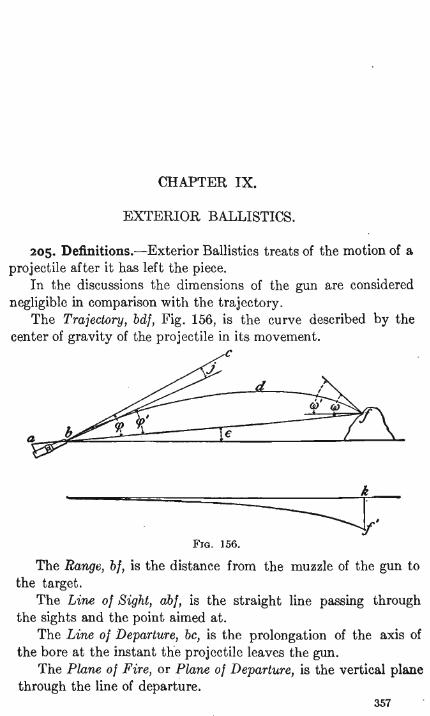
The Trajectory, bdl, Fig. 156, is the curve described by the center of gravity of the projectile in its movement.
c
FIG. 156.
The Range, bl, is the distance from the muzzle of the gun to the target.
The Line 01 Sight, abl, is the straight line passing through the sights and the point aimed at.
The Line 01 Departure, bc, is the prolongation of the axis of the bore at the instant the projectile leaves the gun.
The Plane 01 Fire, or Plane 01 Departure, is the vertical plane through the line of departure.
357
358 ORDNANCE AND GUNNERY.
The Angle of Position, 0, is the angle made by the line of sight with ·the horizontal.
The Angle of Departure, cp, is. the angle made by the line of departure with the line of sight.
The Quadrant Angle of Departure, cp+ 0, is the angle made by the line of departure with the horizontal.
The Angle of Elevation, cp', is the angle between the line of sight and the axis of the piece when the gun is aimed.
The Jump is the angle i through which the axis of the piece moves while the projectile is passing through the bore. The movement of the axis is due to the elasticity of the parts ·of the carriage, to the play in the trunnion beds and between parts of the carriage, and in some cases to the action of the elevating device as the gun recoils. The jump must be determined by experiment for the individual piece in its particular mounting. It usually increases the angle of elevation so that the angle of departure is greater than that angle.
The Point of Fall, f, or Point of Impact, is the point at which the projectile strikes.
The Angle of Fall, w, is the angle made by the tangent to the trajectory with the line of sight at the point of fall.
The Striking Angle, w', is the angle made by the tangent to the trajectory with the horizontal at the point of fall.
Initial Velocity is the velocity of the projectile at the muzzle. Remaining Velocity is the velocity of the projectile at any point
of the trajectory. Drift, leI', is the departure of the projectile from the plane of
fire, due to the resistance of the air and the rotation of the projectile.
Direct Fire is with high velocities, and angles of elevation not exceeding 20 degrees.
Curved Fire is with low velocities, and angles of elevation not exceeding 30 degrees.
High Angle Fire is with angles of elevation exceeding 30 degrees.
206. The Motion of an Oblong Projectile.-The projectile as it issues from the muzzle of the gun has impressed upon it a motion of translation and a motion of rotation about its longer
EXTERIOR BALLISTICS. 359
axis. The guns of our service are rifled with a fight handed twist, and the rotation of the projectile is therefore from left to right . when regarded from the rear. Mter leaving the piece the projectile is a free body acted upon by two extraneous forces, gravity and the resistance of the air.
When the projectile first issues from the piece, its longer axis is tangent to the trajectory. The resistance of the air acts along this tangent, and is at first directly opposed to the motion of translation of the projectile.
The longer axis of the projectile being a stable axis of rotation tends to remain parallel to itself during the passage of the projectile through the air, but the tangent to the trajectory changes its inclination, owing to the action of gravity. The resistance of the air acting always in the direction of the tangent, thus becomes inclined to the longer axis of the projectile, and in modern projectilcs its resultant intersects the longer axis at a point in front of the center of gravity.
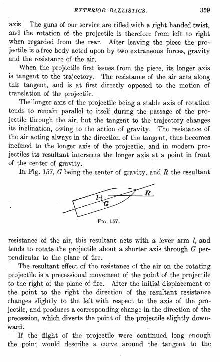
In Fig. 157, G being the centcr of gravity, and R the resultant
R
FIG. 157.
resistance of the air, this resultant acts with a lever arm l, and tends to rotate the projectile about a shorter axis through G perpendicular to the plane of fire.
The resultant effect of the resistance of the air on the rotating projectile is a precessional movement of the point of the projeetile to the right of the plane of fire. Mter the initial displacement of the point to the right the direction of the resultant resistance changes slightly to the left with respect to the axis of the projectile, and produces a corresponding change in the direction of the precession, which diverts the point of the projectile slightly downward.
If the BIght of the projectile were continued long enough the point would describe a curve around the tangent to the
360 ORDNANCE AND GUNNERY.
trajectory; but actually the flight of the projectile is never Idng enough to permit , more ' than a small part of this motion to occur.
The precession of the point is greater as the initial energy of rotation is less. It is therefore necessary to give to the projectile sufficient energy of rotation to make the divergence of the point small. Otherwise the precessional effect may be sufficient to cause the projectile to tumble.
When the point of the projectile leaves the plane of fire the side of the projectile is presented obliquely to the action of the resistance of the air, and a pressure is produced by which the projectile is forced bodily to the right out of the plane of fire. It is to this movement that the greater part of the deviation of the projectile is due.
DRIFT.-The departure of the projectile from the plane of fire, due to the causes above considered, is called drift.
237. Form of Trajectory.-It may be shown analytically that the drift of the projectile increases more rapidly than the range. The trajectory is therefore a curve of double curvature, convex to the plane of fire.
The trajectory ordinarily considered is the projection of the actual curve upon the vertical plane of fire. This projection so nearly agrees with the actual trajectory that the results obtained are practically correct; and the advantage of considering it, instead of the actual curve, is that we need consider only that component of the resistance of the air which acts alorig the longer axis of the projectile and which is directly opposed to the motion of translation.
Determination of the Resistance of the Air.-The relation between the velocity of a projectile and the resistance opposed to its motion by the air has been the subject of numerous experiments.
In the usual method of determining this relation the velocity of the projectile is measured at two points in the trajectory. The points are selected at such a distance apart that the path of the projectile between them may be considered a right line, apd the action of gravity may be neglected. The resistance of the air is then regarded as the only force acting to retard the
EXTERIOR BALLISTICS. 3()1
projectile, and is considered as constant over the path between the two points.
The loss of energy in the projectile, due to the loss of velocity, is the measure of the effect of the resistance of the air, and is equal to the product of the resistance into the path. The resistance thus obtained is the mean resistance, and corresponds to the mean of the two measured velocities.
EARLY EXPERIMENTS.-The first experiments were those of Robins in 1742. For the measurement of velocities he used the ballistic pendulum. His conclusions were, that up to a velocity of 1100 foot seconds the resistance is proportional to the square of the velocity; beyond 1100 f. s. the resistance is nearly three times as great as if calculated by the law of the lower velocities.
Hutton in 1790, with the improved ballistic pendulum, made numerous experiments with large projectiles. His conclusions were that the resistance increases more rapidly than the square of the velocity for low velocities, and for higher velocities that it varies nearly as the square.
General Didion made a series of experiments at Metz in 1840 with spherical projectiles of varying weights. His conclusions
. were that the resistance varied as an expression of the general form a(v2 +bv3 ), a and b being constants. This formula held for low velocities only.
Experiments were again made at l\Ietz in 1857. Electro-ballistic instruments were now used for the measurement of velocities. The conclusions from these experiments were that th~ resistance varies as the cube of the velocity. Experiments by Prof. Helie at Gavre in 1861 gave practically the same results.
The experiments above described were made principally with spherical projectiles. The difference in the nature of the resistance experienced by oblong and spherical projectiles, together with the difference in the velocities, then and later, may account for the wide difference in the results obtained from these and from later experiments.
LATER EXPERIMENTs.-The Rev. Francis Bashforth made exhaustive experiments in England, in 1865 and again in 1880, using comparatively modern projectiles and accurate ballistic instruments. His conclusions were, that for velocities between
3-62 ORDNANCE AND GUNNER}·.
900 and 1100 f. s. the resistance varied as the sixth power of the velocity; between 1100 and 1350 f. s., as the cube of the velocity; and above 1350 f. s., as the square of the velocity.
The most recent experiments are those made by Krupp in 1881 with modem guns, projectiles, and velocities. The results of these experiments were used by General Mayevski in the deduction of the formulas for the resistance of the air which are now generally used.
CONCLUSIONS FROM THE EXPERIMENTs.-The experiments have shown that the resistance of the air varies with the form of the projectile, with its area of cross section, with the velocity of the projectile, and with the density of the air. Considering the form of the projectile the resistance is affected principally by the shape of the head, and by the configuration at the junction of the head and body. The ogival head encounters less resistance than any other form of head. The resistance was found to increase directly with the area of cross section of the projectile, and directly with the density of the air.
208. Mayevski's Formulas for Resistance of the Air.-In expressing the relation between the resistance of the air and the velocity of the projectile, General Mayevski placed the retardation, as determined in Krupp's experiments, equal to an expression which involves, together with an unknown power of the velocity, quantities whose values are dependent on the weight, form, and cross section of the projectile, and on the density of the air.
Calling p the resistance of the air, w the weight of the projectile in pounds, g the acceleration of gravity,
the retardation is pgjw Representing by R the retardation of the projectile, make
R=pg/w=vnA/C (i)
in which A is a constant and n some power of the velocity, both to be determined from the experiments.
THE BALLISTIC COEFFICIENT, ,C.-The quantity C in the equation was given a value
EXTERIOR BALLISTICS.
in which (Jl is the standard density of the air, (J the density at the time of the experiment, c the coefficient of form, d the diameter of the projectile in' inches, w the weight of the projectile in pounds.
363
By the introduction of this coefficient into the value of the retardation, the effect of variations in weight, form, and cross section of the projectile, and in the density of the air, may be considered.
The coefficient of form c was taken as unity for the standard projectiles. For projectiles of a form that offers greater resistance the value of c will be greater than unity. Examination of equation (1) shows that as c increases, and C decreases, the retardation is increased; a result also obtained by increase in d or (J, that is in the cross section of the projectile or in the density of the air; while by an increase in w, C is increased and the retardation is diminished. The coefficient C is therefore the measure of the ballistic efficiency of the projectile.
The value of c for all projeC'tiles in our service is usually taken as unity.
The density of the air is a function of the temperature and of the atmospheric pressure. The values of (JI/ (J for different atmospheric pressures and temperatures are found in Table VI of the ballistic tables.
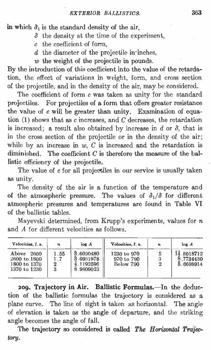
Mayevski determined, from Krupp's experiments, values for n and A for different velocities as follows.
Velocities, f. s . n log A Velocities, f. s. I-~ log A
Above 2600 1.55 3.6090480 1230 to 970 14.8018712 2600 to 1800 1.7 3.09(;1978 970 to 790 3 8 .7734430 1800 to 1370 2 4.1192596 Below 790 2 5 .6698914 1370 to 1230 3 8.9809023
209. Trajectory in Air. Ballistic Formulas.-In the deduction of the ballistic formulas the trajectory is considered as a plane curve. The line of sight is taken as horizontal. The angle of elevation is taken as the angle of departure, and the striking angle becomes the angle of fall.
The trajectory so considered is called The Horizontal Tra]'ectory.
364 ORDNANCE AND GUNNERY.
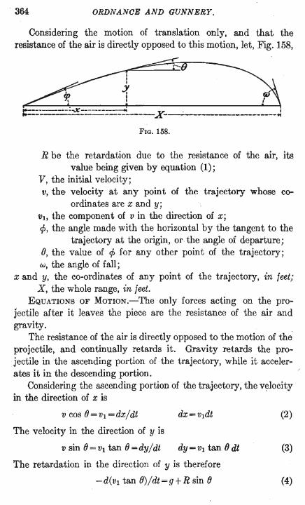
Considering the motion of translation only, and that the resistance of the air is directly opposed to this motion, let, Fig. 158,
~~~ ~ ~ ::--=::'-==':'::~':===:---=~----X--,;;-------------------..:
FIG. 158.
R be the retardation due to the resistance of the air, its value being given by equation (1);
V, the initial velocity; v, the velocity at any point of the trajectory whose co
ordinates are x and y; VI, the component of v in the direction of x; cp, the angle made with the horizontal by the tangent to the
trajectory at the origin, or the angle of departure; (), the value of cp for any other point of the trajectory; w, the angle of fall;
x and y, the co-ordinates of any point of the trajectory, in feet; X, the whole range, in feet.
EQUATIONS OF MOTION.-The only forces acting on the projectile after it leaves the piece are the resistance of the air and gravity.
The resistance of the air is directly opposed to the motion of the projectile, and continually retards it. Gravity retards the projectile in the ascending portion of the trajectory, while it accelerates it in the descending portion.
Considering the ascending portion of the trajectory, the v~locity in the direction of x is
v cos ()=vl=dx/dt dx=v1dt (2)
The velocity in the direction of y is
v sin ()=Vl tan ()=dy/dt dY=Vl tan Odt (3)
The retardation in the direction of y is therefore
-d(Vl tan ())/dt=g+R sin () (4)
EXTERIOR BALLISTICS. 365
Since gravity has no component in a horizontal direction. the retardation in the direction of x is
-dvt/dt=R cos (J dt= -dVI/R cos (J (5)
Substituting this value of dt in (2), (3), and (4), and performing the differentiation indicated in (4), d tan (J being dfJ/cos2(J, we obtain
dx = - vIdvt/R cos (J
dy = - VI tan (J dvt/R cos 0
dfJ=g cos (J dvt/Rvi
(6)
(7)
(8)
The four equations (5) to (8) are the differential equations of motion of the projectile, and if they could be integrated directly they would give the values of t, x, y, and (J for any point of the trajectory. But as they are expressed in terms of R, v, and (J,
three independent variables, the direct integration is impossible. The value of R is given by Mayevski's formulas, R=Avn/C,
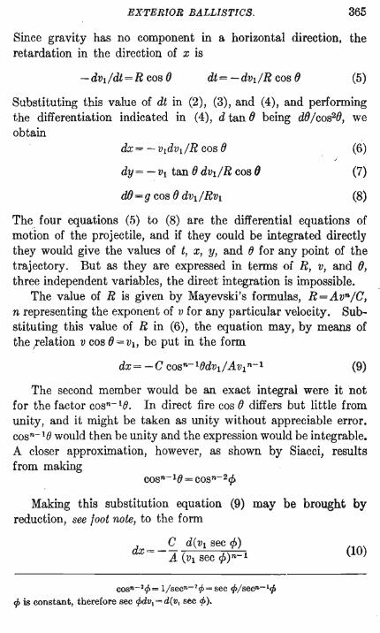
n representing the exponent of V for any particular velocity. Substituting this value of R in (6), the equation may, by means of the felation v cos (J = VI, be put in the form
(9)
The second member would be an exact integral were it not for the factor cosn-1(J. In direct fire cos (J differs but little from unity, and it might be taken as unity without appreciable error. cosn-1(J would then be unity and the expression would be integrable. A closer approximation, however, as shown by Siacci, results from making
cosn-l(J = cosn-2cjJ
Making this substitution equation (9) may be brought by reduction, see foot note, to the form
dx= _ C d(Vl sec cjJ) A (VI sec cjJ)n-1
cosn-2rp= 1/secn - 2 rp=sec if>/secn-1cp if> is constant, therefore sec cf>dV1 = d( V, sec </».
(10)
366
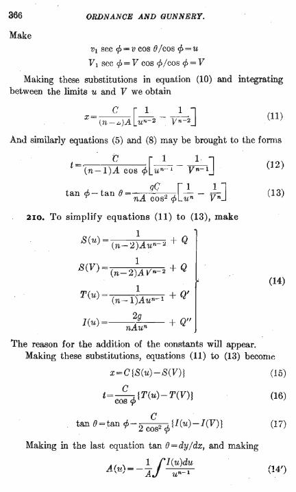
Make
ORDNANCE AND GUNNERY.
VI sec 1> = V cos 0/ cos 1> = U
VI sec 1>= V cos 1>/COS 1>= V
Making these substitutions in equation (10) and integrating between the limits u and V we obtain
c [1 1 ] X= (n-..,)Ji un-2 - Vn-2
(11)
And similarly equations (5) and (8) may be brought to the forms
elI t= (n-l)A cos ¢[Un--l - vn-I]
qC) [1 IJ tan ¢ - tan 0 nA cos2 ¢ un - Vn
210. To simplify equations (11) to (13), make
1 S(u) = (n-2)Au n- 2 + Q
1 S(V) = (n-2)AVn 2 + Q
T(u) = (n-15Aun- I + Q'
leu) = __ 2g + Q" nAun
The reason for the addition of the constants will appear.
(12)
(13)
(14)
Making these substitutions, equations (11) to (13) beconw
x=C1S(u)-S(V)1
C t= cos 1>l T (u)-T(V)}
C tan e = tan 1>- 2 cos2 ¢ {l(u) - I(V)}
Making in the last equation tan O=dy/dx, and making
At 1,\=_!jl(U)dU __ ,U, A un-1
(15)
(16)
(17)
(14')
EXTERIOR BALLISTICS. 367
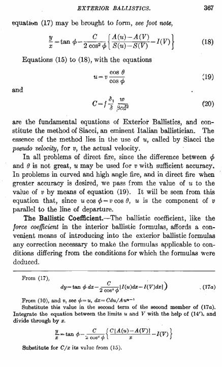
equatlttn (17) may be brought to form, see foot note,
y C {A(u)-A(V) } -X=tancp-2cos2cp S(u)-S(V) leV) (18)
Equations (15) to (18), with the equations
cos () u=v--cos cp ~19)
and 0'1 w
C=f-a iJCd2 , (20)
are the fundamental equations of Exterior Ballistics, and constitute the method of Siacci, an eminent Italian ballistician. The essence of the method lies in the use of u, called by Siacci the pseudo velocity, for v, the actual velocity.
In all problems of direct fire, since the difference between cp and () is not great, u may be used for v with sufficient accuracy. In problems in curved and high angle fire, and in direct fire when greater accuracy is desired, we pass from the value of u to the value of v by means of equation (19). It will be seen from this equation that, since u cos cp=v cos (), u is the component of v parallel to the line of departure.
The Ballistic Coefficient.-The ballistic coefficient, like the force coefficient in the interior ballistic formulas, affords a convenient means of introducing into the exterior ballistic formulas any correction necessary to make the formulas applicable to conditions differing from the conditions for which the formulas were deduced.
From (17),
dy=tan eft dX-2
c" ",{I(u)dx-I(V)dxl) cos 't'
, (I7a)
From (10), and v, sec rp=u, dx=Cdu/Aun-'
Substitute this value in the second term of the second member of (I7a). Integrate the equation between the limits u and V with the help of (14'). and divide through by x.
!L=tan rp _ _ C_._{ C{A(u)-A(V)! -I(V)} x ~ cos" rp x
Substitute for C/x its value from (15).
3"68 ORDNANCE AND GUNNERY.
For general use with the fonnulas of exterior ballistics Mayevski's value for C, page 362, is changed by the introduction of two quantities, f and p, so that the value of the ballistic coefficient takes the fonn written in equation (20).
f is called the altitude factor, and brings into consideration the diminution in the density of the air as the altitude of the trajectory increases. The value of f is greater than unity and depends upon the mean altitude of the trajectory, which is taken as two-thirds of the maximum altitude.
p is an integrating factor, and corrects for the error due to certain assumptions made in deducing the primary equations, when . these equations are applied to a trajectory whose curvature. is considerable. p is approximately unity in all problems of direct fire. The product pc is called the coefficient of reduction.
When in the statements of ballistic problems the data required to determine fJd fJ, P or c is not given, the value unity is assumed jar the factor. f is also assumed as unity unless a correction for altitude is desired. When all these factors are unity the ballistio coefficient becomes
C=w/dJ
2 I I. The Functions.-The functional expressions in equations (15) to (18) are called: S(u) the space function, T(u) the time function, leu) the inclination function, and A(u) the altitude function. Their values are given by the equations (14) and (14'). The values of these functions for values of u from 3600 to 100 foot seconds have been calculated, and form Table I of the Ballistic Tables.
Since V is a particular value of u the values of the functions of V are included in the table as values of the functions of u. For example, to find the value of S(V), V being given, enter the table with the value of V as a value of u and take out the corresponding value of S(u).
The quantities Q, Of, and Q", in the values of the functions, equations (14), are arbitrary constants; and the purpose of including them is to provide a means for avoiding abrupt changes in the tables at those points where in Mayevski's formulas the values of A and n change.
EXTERIOR BALLISTICS. 369
CALCULATION OF THE FUNCTIONS.-The method of employing the constants in forming the tables is best shown by an example. The value of the S function is, equation (14),
1 S(u) = (n-2)Aun - 2+ Q
For va~ues of v greater than 2600 f. s., we have from Mayevski's formulas, n = 1.55. Therefore for a velocity greater than 2600 f. s.
U°.45 1 S(u) = ---~. -+Q= --_('uO.45 +Ql)
0.45A1 0.45A1
In order to avoid the use of large numbers Table I of the latest ballistic tables, published in 1900, is so constructed that the S, A, and T functions reduce to zero for u=3600. leu) reduces te> zero for U= 00. We have then for S(u), whenu=3600
and therefore Ql = - (3600)0.46
For any other value of u down to 2600
1 --0.45 S(u)=--(3600 -UO.45)=K-K'uO.4~ (21)
0.45A1
For velocities between 2600 and 1800 f. s., n=1.7, and
1 S(u) = - 0.3A2 (UO.3 +Q2)
Qz must have such a value as to make the value of S(u) for u=2600 the same as the value determined from equation (21) with this value of u. Therefore
1 --0.3 --'0.45 ---(2600 +Q2)=K-K'2600
0.3A2
from which the value of Q2 ~can be determined. The same process is followed at each change in the values of
nand A.
370 ORD.vANCE. AND GUNNERY.
When n = 2 equation (11) becomes indeterminate and the values of the functions cannot be determined as above; but making n=2 in eqQation (10) and integrating we obtain
C X= - A (lo.ge u-Iog, V)
S(u) becomes in this case
S(U)=_lo~u+Q
INTERPOLATION IN TABLE I.-This is effected by the ordinary rules of propo.rtional parts. The difference between successive values of u varies from unity in one part of the table to 2, 5, and 10 in o.ther parts. This difference must be carefully noted in interpolating.
212. Formulas for the Whole Range.-Designate the whole range, Fig. 158, by X, the corresponding time of flight by T, the angle of fall (considered positive for convenience) by w, and use the subscript OJ to designate the values of u and v at the point of fall.
At the point of fall y = 0 and () = -: w; and after combining equations (17) and (18) to eliminate I(V) from (17), equations (15) to (19) become, respectively,
X =C!SCuw)-S(V)1
C T= cos 1>!T(uw)-T(V)1
C r A(Uw)-A(V)} tan w=2 C0.821> 1 I(uw)- S(u,,J-S(V)
• 2 "'=C r A(u",)-AeV) ICV) 1 sm 't' 1 S(Uw)-S(V) j
Uw = Vw cos w/cos 1>
(22)
(23)
(24)
. (25)
(26)
At the summit of the trajectory (}=o. Using the subscript 0
to designate the summit, equations (17) and (19) become, after reduction,
EXTERIOR BALLISTICS.
Combining (27) and (25) we have
l( ) = A(uw)~A(V) U
o S(u .. )-S(V)
Therefore (24) and (25) become
C tan W=2 2 A- jl(u",)-I(uoH cos 't'
sin 2 cp=Cjl(uo)-I(V)1
371
(29)
(30)
(31)
213. The Ballistic Elements.-The quantities C, u, V, cp~ 0, w, T, and X in the previous equations are called the ballistic elements. When referring to the end of the range they are written as capitals, or with the sUbscript w' For any other point of the trajectory they are written as small letters, with suitable sUbscript if desired. The subscript 0 always refers to the summit of the traject?ry. The equations, by reason of Siacci's assumption for the value of cosn-10, express the relations existing between these elements in direct fire only.
When three or more of the elements are given the others may be determined.
The Rigidity of the Trajectory.-According to the principle of the rigidity of the trajectory, which is mathematically demonstrated, the relations existing between the trajectory and the chord representing the rang3 are sensibly the same whether the chord be horizontal or inclinec! to the horizon, provided that the fJ,uadrant angle of departure and the angle of position are small or that' the difference between them is small. That is to say t,hat, considering cp + e and e as small, in Fig. 156, if the trajectory bdf and its chord bf were revolved about the pointb until bt were horizontal, the relation of the trajectory to bt would not change. A trajectory calculated for a horizontal range equal to bt would then answer as the trajeetory for the actual inclined range bt.
Therefore when the quadrant angle of departure,cp+ e, is small we may consider bf, or any other chord of the trajectory, as a horizontal range; and we may apply to the trajectory subtended by the chord theJormulas deduced for a horizontal range.
If how~ver the quadrant angle of departure is large, the prin-
372 ORDNANCE AND GUNNERY.
eiple of the rigidity of the trajectory applies only when the angle of position is also large, that is when ¢+ e does not differ much from e. Therefore in any complete high angle trajectory for a horizontal range the principle of the rigidity of the trajectory applies only to a part of the trajectory near the origin. This part may be treated as a horizontal range whose angle of departure is the difference between the quadrant angle of departure of the horizontal trajectory and the angle of position.
When the difference between ¢+ e and e is small, ¢ must be small. It is therefore evident that, in direct fire, the principle of the rigidity of the trajectory applies whenever the angle of . departure is small.
This principle eIlli.bles us to use the elements calculated for a horizontal range when firing at objects situated above or below the level of the gun.
214. Use of the Formulas.-The method of using the formulas may best be shown by considering a problem.
Problem I.-What is the time of flight of a 3-inch projectile weighing 15 lbs., for a range of 2000 yards; muzzle velocity, 1700 f. s.?
The given data are C=15/ 9, V=1700, and X =6000, the range being always taken in feet . T is required.
These formulas apply:
C T= cos ¢{T(uw)- T(V)J
sin 2¢=C {~~~:~=:(~1 I(V)}
Take the T, S, A, and I functions of V from Table 1. Determine S(uw ) from (22).
(23)
(25)
(22)
Find Uw from Table I, and take from the Table T(u.,) and A(u .. ).
Find ¢ from (25). Find T, required, from (23). Ans. T=4.48 seconds. 215. Secondary Functions.-The most important problems in
gunnery may be solved by means of equations (22) to (31) and
EXTERIOR BALLISTICS. 373
ballistic Table I, but some of the solutions are indirect and tentative and therefore very laborious. The processes of solution have been greatly abbreviated and the labor greatly reduced by the introduction of secondary functions, whose values, for all the requirements of modern gunnery, have been calculated and collected in Table II of the ballistic tables.
The development of the science of exterior ballistics to its present accuracy and comparative simplicity is principally due to Colonel James M. Ingalls, U. S. Anny, whose interior ballistics are set . forth in Chapter III.
From equation (15) we have
S(u) =x/C+S(V)
and substituting the values of S(u) and S(V), see (14),
1 x 1 (n- 2)Aun 2 = C + (n- 2)A Vn-2
From this equation it is apparent that the value of the pseudo ' velocity u, at any point, is a function of x/C and V only, and is independent of the height of the point in the trajectory.
Make z=x/C Z=X/C
It will be seen in equations (16), (17), and (1~) that t, 0, and y are functions of u and therefore also functions of z and of V.
The secondary functions, whose values are here' given, are all functions of Z and V, and are tabulated with Z and Vas arguments.
A =A(u)-A(V) I(V) S(u)-S(V)
B =I(u)- A(u)-A(V) S(u)-S(V)
A' =A+B=I(u)-I(V)
T' = T(u) - T(V)
B'=B/A
(32)
'rhe subscripts are dropped in these expressions since they only serve to indicate particular values of u, while the table contains the values of A, B, etc., for all the values of u.
374 ORDNANCE AND GUNNERY.
The table also contains, in the column u, the values of u for all values of Z and V.
Equations (23), (24), and (25) may now be put, by reduction, into the following exceedingly simple forms.
T =CT' /cos cp
sin 2 cp=AC
tan w = BC /2 cos2 cp = B' tan cp
Equations (17) and (18) may also be put in the forms
tan cp tanO=A-(A-a')
_ x tan CP(A ) y- A -a
(33)
(34)
(35)
(36)
(37)
In these equations a and a' are the values of A and A' corresponding to z = x/C for-the particular point of the trajectory considered, while A and A' are the values corresponding to Z =X/C for the whole range.
216. At the summit tan 0 reduces to zero; and we obtain from equation (36), writing ao'for a' at the summit, .
ao'=A (38)
Equation (37) then becomes
Xo tan cP , Yo= , (ao -aD) , ao (38')
From the third equation (32) we have for the summit bo=ao' -ao. With this relation and the relation zo=xo/C, and making
ao" = bozo/ ao'
equation (38') reduces to the form
yo=ao"C tan cp
yo representing the maximum ordinate.
(39)
To obtain ao" for use in this equation we find in Table II, in the A' column,. the value of A as determined for the whole
EXTERIOR BALLISTICS. 375
range. With this value as A' and th~ given value of V we find ao" in the A" column. '
Write Z =X/C (40)
v=u cos 1>/cos (j (41)
a=' f 31 '!!!- (42) 3 cd2
and ..
. 1 [3.79239] C2D' /cos3 1> (~e, ac, oa,st, guns) DrIft (yds.) = _ (43) [3.92428] C2D' /cos3 1> (field guns)
which is Mayevski's formula for drift, abbreviated for tabulation by Colonel Ingalls. The values of D' are found in Table II.
We have in the equations (33) to (43) the principal fOrlIlulas required for the solution of nearly all the problems of direct fire.
While the fOrlIlulas apply strictly to direct fire only, where the values of 1> and 0 are such as to perlIlit the use of Siacci's value of cosn-10 without appreciable error, they give sufficiently accu- ' rate results for curved fire, and they are used for curved fire as well.
They are made applicable to high angle fire by giving to the coefficient c in the ballistic coefficient such values as will make the results obtained from the fOrlIlulas agree with the results obtained in actual firings. For the low velocities used in mortars and howitzers the fOrlIlulas are simplified, as will later be shown.
Ballistic Tables.-The Ballistic Tables, which are issued by the War Department, consist of three volumes,entitled: Artillery Circ:ular M, Series of 1893 (printed in 1900), Supplement to Artillery Circular M (1903), and Supplement No. 93 to Artillery Circular M (1904). The supplements extend Tables II, IV, and V of Artillery Circular M.
In addition there has appeared a simplification of Table IV in the Journal of the United States Artillery, number for January and February, 1905.
Artillery Notes, No. 935, issued by the War Department, 1905, contains a corrected table to replace Table VI of Artillery Circular M, the latter table having been found to be based on incorrect data.
The ballistic fOrlIlulas are found assembled on page VIII of the
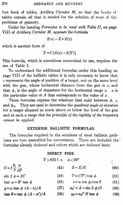
,,376 ORDNANCE AND GUNNERY.
first book of tables, Artillery Circular M, so that the books of tables contain all that is needed for the solution of most of the problems of gunnery.
Under the heading Formulas to be used with Toole II, on page VIn of Artillery Circular M, appears 'the formula
S(u) =Z+S(v)
which is another form of
x =CjS(u)-S(V)l
This formula, which is sometimes convenient to use, requires the ,use of Table 1.
To understand the additional formulas under this heading on , page VIII of the ballistic tables it is only necessary to know that
E represents the angle of position of a target, not on the same level with the gun, whose horizontal distance from the gun is x, and
, that cf>x is the angle of departure for the horizontal range x. a is the particular value of A that corresponds to the value of x.
These fommlas express the relations that exist between 'cf>, E,
and cf>",. They are used to determine the quadrant angle of elevation for a target situated so much above or below the level of the gun and, at such a range that the principle of the rigidity of the trajectory cannot be applied.
EXTERIOR BALLISTIC FORMULAS.
The formulas required in the solutions of most ballistic problems are here assembled for convenience. There are included the' formulas already deduced and others which are deduced later.
DIRECT FIRE.
V>825 f. s. cf><20o I, G=f~l~ (42) Z=X/G (40)
~ciP
sin 2 cf>=AC (34) T = CT' /cos cf> (33)
tan (j) = B' tan cf> (35) v = u cos cf>/cos () (41)
y=x tan cf> (A-a)/A (37) ao' =A = sin 2 cf>/O (38)
,tan (}=tan cf> (A-a')/A (36) Yo = ao" a tan cf> (39)
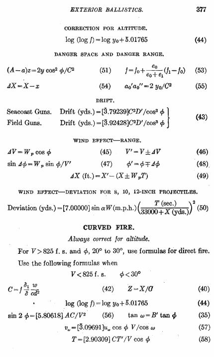
EXTERIOR BALLISTICS. 377
CORRECTION FOR ALTITUDE.
log (log I) = log Yo+5.01765 (44)
DANGER SPACE AND DANGER RANGE.
(A-a)z=2y cos2 1>/C2 (51) eo (53) 1=/0+--(/1-/0) eO+el
JX=X-x (54) ao' ao" = 2 yo/C2 (55)
DRIFT.
Seacoast Guns. Drift (yds.) - [3. 79239]C'D' / cos' qI }
Field Guns. Drift (yds.) = [3 .92428]C2D' /cos3 rp (43)
WIND EFFECT-RANGE •
.,dV = W p cos cf> (45) V'=V±.,dV (46)
sin.,d¢ =W p sin 1>iV' (47) ¢' = ¢"T Jrp (48),
.,dX (ft.) =X' ~ (X ± W pT) (49)
WIND EFFECT-DEVIATION FOR 8, 10, 12-INCH PROJECTILES.
Deviation (yds.) =[7.00000] SinaW(m.p.h.)(33~~~c&ds.)r (50)
CURVED FIRE.
Always correct tor altitude.
For V>825 f. s. and 1>,20° to 30°, use formulas for direct fire.
Use the following formulas when
V <825 f. s. 1><30°
(42)z=x/a (40)
log (log f)=log yo+5.01765 (44)
sin 21>=[5.80618]AC/V2 (56) tan w=B' tan q;, (35)
v'" = [3.09691]u", cos 1> V /cos w (57)
T = [2.90309] CT'IV cos 1> (58)
378 ORDNANCE AND GUNNERY.
mGH ANGLE FIRE.
1»300
Always correct lor aUitude.
When the coefficient of reduction c is known use Table IV. When the coefficient of reduction is not known use the formulas
for direct fire· and Table II, or Table I in those problems for which Table II is not sufficiently extended.
CURVATURE · OF EARTH.
Curvature (ft.) = [7.33289}X2 (yds.) (59)
217. Interpolation in Table n.-Exact formulas for interpolation in Table II are deduced and explained in the appendix to this chapter. These formulas greatly facilitate the solution of ballistic problems; A thorough understanding, of the interpolation formulas, and facility in their use, shou~d be acquired before proceeding further. These formulas, which Ihe here written, will be used in place of the interpolation formulas given on page VIII of the ballistic tables, as the latter formulas are approximate ' only~
Double Interpolation Formu1as~Ballistic Table ll . .
I = non-tabular value of any function corresponding to the non, tabular values V and Z.
lo=tabular value of function corresponding to tabular values Vo . and Zo always next less than V and Z. \ ., '
h = difference between velocities given in caption of table. Jvo and Jzo = tabular differences for 10. JVl = tabular difference next following Jvo in same table. I ~:; ~~ indicates that function decreases as V increases, and increases
oe.s Z increases. ' Use the following formulas for the functions A, A', B, T', log\
G', .and D' throughout the table. They also apply for some values. of the functions A" and log B' when V> 2500.
-v ' Z-Zo V-VoZ-Zo V- Vo I~+g=/o+ 100 Jzo--h-Jvo- 100 '-h-(JVl-dvo)
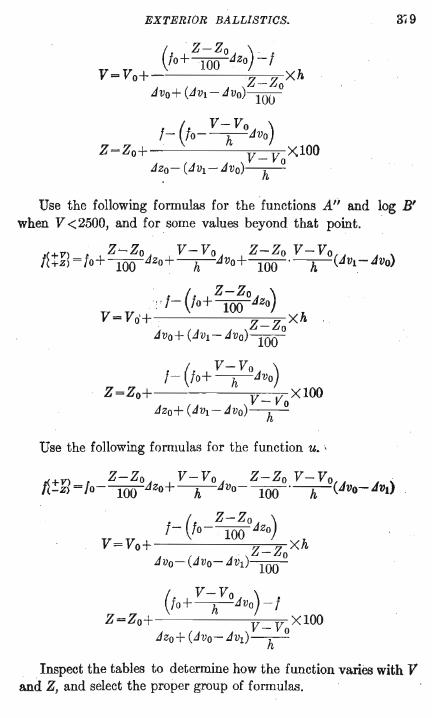
EXTERIOR BALLISTICS. 3/9
( V- Vo ) /- /0- -h-Jvo
Z=Zo+ V_VoX100 Jzo- (JVl - JVo)-h-
Use the following formulas for the functions A" and log B' when V <2500, and for some values beyond that point.
+v Z~Zo V-Vo Z-Zo V-Vo 1~+zl=/o+~Jzo+-h-Jvo+----WO·-h-(JVl-JVO)
( Z-Zo ) " /- /0+ --Jzo , 100
V=Vo+ Z_ZoXh Jvo+ (JV1- Jvo)lOO
(V - Vo )
f- /0+ -h-Jvo
Z=Zo+ v- Vo XlOO Jzo+ (JVl - JVo)-h-
Use the following fommlas for the function u. '
(/0 + V~VoJvo)_f Z=Zo+ V_VoX100
Jzo+ (Jvo- JV1)-h-
Inspect the tables to determine how the function varies with V and Z, and select the proper group of formulas.
380 ORDNANCE AND GUNNERY.
Exercise great care in the use of the plus and minus signs. As the numbers in the difference columns of the table are
written as whole numbers we must, when using the interpolation formulas, treat the tabular values of the functions as whole numbers, and afterwards put the decimal point where it belongs.
Regarding the interpolation formulas we will note that the proportional parts of the differences Jzo and Jvo are always applied to the tabular value of the function, 10, with a sign indicated by the manner of variation of the function with Z and V respectively; positive if the function is increasing, negative for a decreasing function. The sign of the last term of the I formulas is positive if the signs of the preceding terms are similar, and negative if they are dissimilar.
In the formulas for V and Z the fractional coefficients of hand V- Vo Z-Zo
100 are equal respectively to --h- and -WO. These coefficients
will always indicate by their values whether we are working with the proper tabular values. Numerator and denominator 01 the lraction should always be positive, and the value 01 the fraction less than t~nity.
218. The Solution of Pro blems.-With the ballistic formulas and the tables, the solutions of the problems of gunnery become very simple. We will remember that all the functions in Table II are functions of V and of Z =XjC, the arguments of the table. Therefore, given any two of the three quantities, V, Z, and a value of a function, the third may be determined from the table, and also the corresponding value of any other function in the table. For instance, suppose V and A' are given and the corresponding values of A", log B' and T' are required. With V and A' we may , obtain Z from the table, and with V and Z we obtain A", log B' and T'.
Inspecting the formulas, pages 376 and 377, we select those that contain the given quantities, and such other formulas as, with Table II, will enable us to pass to the formula containing the required quantity.
It must be remembered that in the formulas the large letters represent values of the quantities for the whole range, or complete horizontal trajectory; while the small letters represent values of
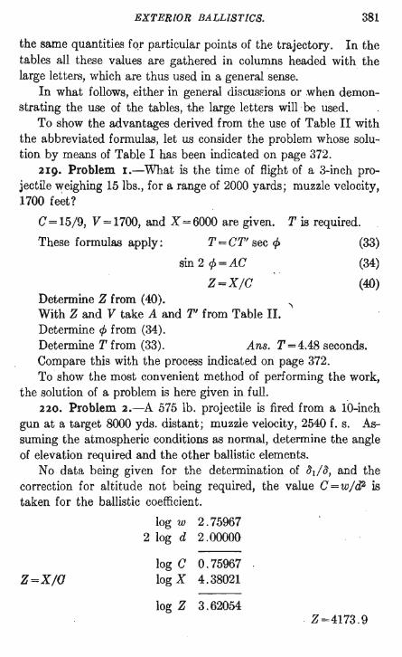
EXTERIOR BALLISTICS. 381
the same quantities fqr particular points of the trajectory. In the tables all these values are gathered in columns headed with the large letters, which are thus used in a general sense.
In what follows, either in general discusEions or when demonstrating _ the use of the tables, the large letters will -be used.
To show the advantages derived from the use of Table II with the abbreviated formulas, let us consider the problem whose solution by means of Table I has been indicated on page 372.
219. Problem I.-What is the time of flight of a 3-inch projectile weighing 15 lbs., for a range of 2000 yards; muzzle velocity, 1700 feet?
C=15j9, V=1700, and X=6000 are given. T is required.
These formulas apply: T = CT' sec 1>
Determine Z from (40).
sin 2 1>=AC
Z=XjC
With Z and V take A and T' from Table II. Determine 1> from (34).
(33)
(34)
(40)
Determine T from (33). Ans. T = 4.48 seconds. Compare this with the process indicated on page 372. To show the most convenient method of performing the work,
the solution of a problem is here given in full. 220. Problem 2.-A 575 lb. projectile is fired from a 10-inch
gun at a target 8000 yds. distant; muzzle velocity, 2540 f. s. Assuming the atmospheric conditions as normal, determine the angle of elevation required and the other ballistic elements.
No data being given for the determination of /Jd/J, and the correction for altitude not being required, the value C=wjd2 is taken for the ballistic coefficient.
log w 2.75967 2 log d 2 .00000
log C 0.75967 Z=XjO log X 4.38021
log Z 3.62054 . Z=4173 .9
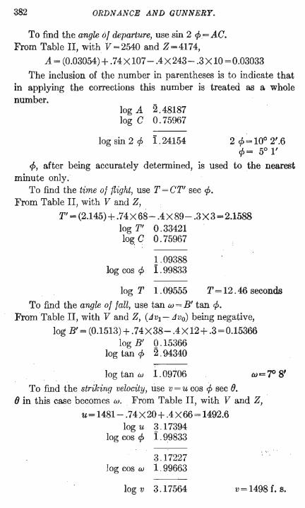
382 ORDNANCE AND GUNNERY.
To find the angle of departure, use sin 2 1>=AC. From Table II, with V = 2540 and Z = 4174,
A= (0.03054)+.74X107- AX243- .3XlO=0.03033
The inclusion of the number in parentheses is to indicate that in applying the corrections this number is treated as a whole number.
log A 2.48187 log C 0.75967
log sin 2 1> i .24154 2 1>= 10° 2'.6 1>= 5° l'
1>, after being accurately determined, is used to the nearest minute only.
To find the time of flight, use T = CT'sec 1>. From Table II, with V and Z,
T' =(2.145)+ .74X68- AX89- .3X3=2.1588 log T' 0 . 33421 log C 0 . 75967
1.09388 log cos 1> i . 99833
log T 1 .09555 T = 12 . 46 seconds
To find the angle of fall, use tan w = B' tan 1>. From Table II, with V and Z, (JVl - ,dvo) being negative,
log B' = (0.1513) + .74X38- AX12+ .3=0.15366 log B' Q. 15366
log tan 1> 2 .94340
log tan w 1.09706 w='? 8' To find the striking velocity, use v = u cos 1> sec e.
() in this case becomes w. From Table II, with V and Z,
u=1481- .74X20+ .4X66=1492.6 log u 3 . 17394
log cos 1> i . 99833
3.17227 Jog cos w 1. 99663
log v 3.17564
,- \' .
v=1498 f. s.
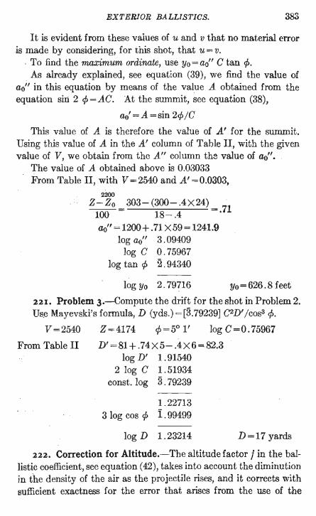
EXTERIOR BALLISTICS. 383
It is evident from these values of u and v that no material error is made by considering, for this shot, that u = v.
, To find the maximum ordinate, use yo = ao" C tan ¢. As already explained, see equation (39), we find the value of
ao" in this equation by means of the value A obtained from the equation sirt 2 ¢=AC. At the summit, see equation (38),
ao' =A =sin 2¢jC
This value of A is therefore the value of A' for the summit. Using this value of A in the A' column of Table II, with the given value of V, we obtain from the A" column the value of ao".
The value of A obtained above is 0.03033 From Table II, with V = 2540 and A' = 0.0303,
2200
Z-Zo = 303- (300- .4 X 24) = 71 100 18-.4 . ao" = 1200 + . 71 X 59 = 1241.9
log ao" 3 . 09409 log CO. 75967
log tan ¢ 2 .94340
log Yo 2.79716 yo=626.8 feet
221. Problem 3.-Compute the drift for the shot in Problem 2. Us~ Mayevski's formula, D (yds.) =[3.79239] C2D' jcos3 ¢.
V=2540 Z=4174 ¢=5°1' 10gC=0.75967
From Table II D'=81+.74X5-.4X6=82.3 log D' 1 .91540
2 log C 1.51934 const. log 3 . 79239
1.22713 3 log cos ¢ i . 99499
log D 1.23214 D=17 yards
222. Correction for Altitude.-The altitude factor f in the ballistic coefficient, see equation (42), takes into account the diminution in the density of the air as the projectile rises, and it corrects with sufficient exactness for the error that arises from the use of the
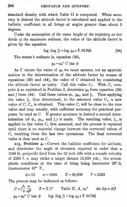
384 ORDNANCE AND GUNNERY.
standard density with which Table II is computed. When accuracy is desired the altitude factor is calculated and applied to the ballisti~ coefficient in all firings at angles greater than about 5 degrees.
Under the assumption 01 the mean height 01 the trajectory as two thirds 01 the maximum ordinate, the value of the altitude factor is given by the equation
log (log I) = log yo+5 .01765 [44]
The summ't ordinate is, equation (39),
Yo = ao" C tan cP
As C enters the value of yo we must assume, tor an approximation in the determination of the altitude factor by means of equations (39) and (44), the value of C obtained by considering the altitude factor as unity. Call this value C1• With C1 compute cP as explained in Problem 2, determine yo from equation (39) and 1 from (44). Call these values CPt, yO!. and /to Then applying the value /t, thus determined, to the assumed value C1, a new value of C, Ce, is obtainE:ld. This value Ce will be close to the true value and may usually, with sufficient accuracy for practical purposes, be used as C. If greater accuracy is desired a second determination (of cP e, yo e, and Ie) is made. The resulting value, Ie, is applied to the value C1 first assumed, and the process is repeated until there is no material change between the corrected values of C1 resulting from the last two operations. The final corrected value is then used as C.
223. Problem 4.-Correct the ballistic coefficient for alt1tude, and determine the angle of elevation required in order that a 1048 lb. projectile fired from the 12 inch rifle with a muzzle velocity of 2350 f. S. may strike a target distant 12,000 yds.; the atmos~ pheric conditions at the time of firing being barometer 29".5, thermometer 67° F.,
d=12 w=1048 X =36,000 V=2350
The process may be indicated as follows:
C=/~l ~ Z=X/C Table II, A, ao" ~ cd2 sin 2cp=Aa
log (log f) = log Yo + 5.01765 Yo = ao" C tan cP
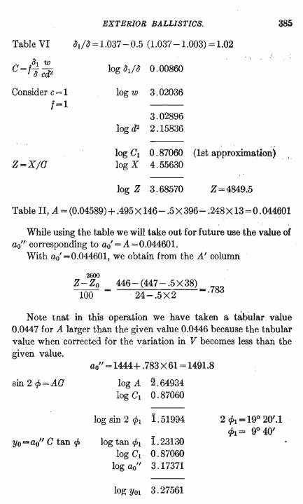
EXTERIOR BALLISTICS. 385
Table VI Jt/J= 1.037 -0.5 (1.037-1.003) = 1.02
c=l;;
; ,
log ;hliJ 0.00860
Consider c = 1 log w 3.02036 1=1
3.02896 log d2 2.15836
. .. log C1 0.87060 (1st approximation)
. I.
Z=X/G log X 4.55630
log Z 3.68570 Z=4849.5
Table II, A = (0.04589)+ .495 X 146- .5X396- .248X13=0.044601
While using the table we will take out for future use the value of ao'" corresponding to ao' = A = 0.044601.
With ao' =0.044601, we obtain from the A' column
2600
Z-Zo = 446-(447-.5X38) = 783 100 . 24-.5X2 .
Note tnat in this operation we have taken a tabular value 0.0447 for A larger than the given value 0.0446 because the tabular value when corrected for the variation in V becomes less than the given value.
sin 2 cp=AO
yo=ao" C tan cp
ao" = 1444+ .783X61 =1491.8
log A 2 . 64934 log C1 0 .87060
log sin 2 CPl 1.51994
log tan CPl 1.23130 log Cl 0.87060
log ao" 3.17371
log YOl 3.27561
2ch =190 20'.1 P1 = 90 40'
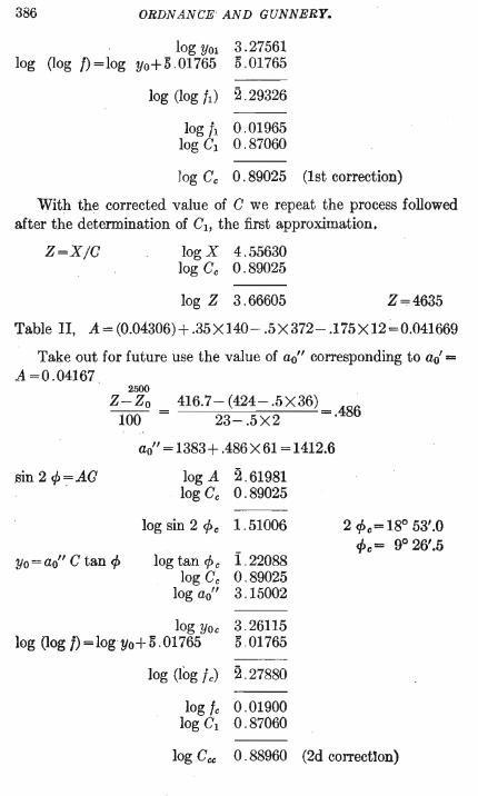
386 ORDNANCE AND GUNNERY.
log YOl 3.27561 log (log f) = log Yo+5.01765 5.01765
---log (log h) 2.29326
logl 0.01965 log 1 0.87060
Jog Cc 0.89025 (1st correction)
With the corrected value of C we repeat the process followed after the determination of C1, the first approximation.
Z=XjC log X 4.55630 log Cc 0.89025
log Z 3 . 66605 Z = 4635
Table II, A= (0.04306)+.35X140- .5X372- .175X12~0.041669
Take out for future use the value of ao" corresponding to ao' = A=0.04167
2500
Z-Zo = 416.7- (424- .5X36) = 486 100 23-.5X2 .
sin 2 cp=AG
ao" = 1383 + .486 X 61 = 1412.6
log A 2.61981 log Cc 0.89025
log sin 2 CPc 1.51006
yo = ao" C tan cP log tan cp c 1. 22088 log Cc 0.89025
log ao" 3 .15002
log YOc 3.26115 log (log f)=logyo+5.01765 5.01765
log (log f c) 2 . 27880
logic 0.01900 log C1 0.87060
2 CPc= 18° 53'.0 CPc= 9° 26'.5
log Ccc 0.88960 (2d correction)
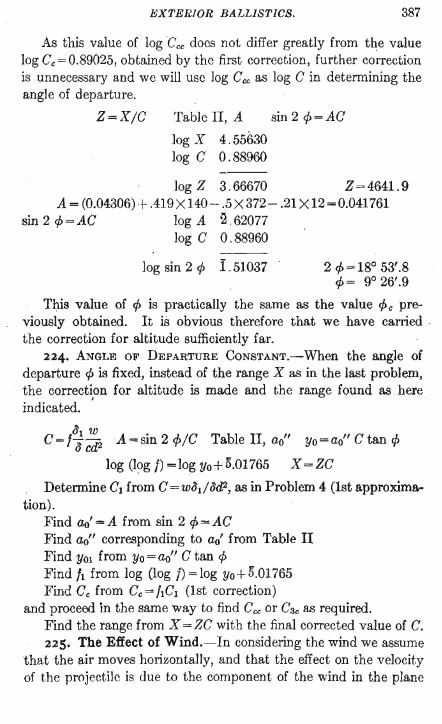
EXTERIOR BALLISTICS. 387
As this value of log Cee does not differ greatly from the value log Ce = 0.89025, obtained by the first correction, further correction is unnecessary and we will use log Cce as log C in determining the angle of departure.
Z=X/C Table II, A sin 2 ¢ = AC
log X 4.55630 log CO. 88960
log Z 3.66670 Z = 4641. 9 A = (0.04306) -+- .419 X 140 - .5 X 372 - .21 X 12 = 0.041761
sin 2 ¢=AC log A 2 .62077 log CO. 88960
log sin 2 ¢ I . 51037 2 ¢=18° 53'.8 ¢= 9° 26'.9
This value of ¢ is practically the same as the value ¢ e previously obtained. It is obvious therefore that we have carried . the correction for altitude sufficiently far.
224. ANGLE OF DEPARTURE CONSTANT.-When the angle of departure ¢ is fixed, instead of the range X as in the last problem, the correction for altitude is made and the range found as here indicated. '
C=f~ ~2 'A=sin 2 ¢/C Table II, ao" yo=ao" C tan ¢
log (log f) = log yo+5.01765 X =ZC
Determine Cl from C=wat/ad2, as in Problem 4 (1st approxima-tion).
Find ao' =A from sin 2 ¢=AC Find ao" corresponding to ao' from Table II Find YOl from yo = ao" C tan ¢ Find It from log (log f) = log yo+5.01765 Find Cc from Cc=hCl (1st correction)
and proceed in the same way to find Cce or C3e as required. Find the range from X = ZC with the final corrected value of C. 225. The Effect of Wind.-In considering the wind we assume
that the air moves horizontally, and that the effect on the velocity of the projectile is due to the component of the wind in the plane
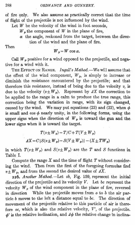
388 ORDNANCE AND GUNNERY.
of fire c;mly. We also assume as practically correct that the time of flight of the projectile is not influenced by the wind.
Let W be the veloCity of the wind in foot seconds, W p the component of W in the plane of fire, a the angle, reckoned from the target, between the direc
tion of the wind and the plane of fire. Then
W p=;= W cos a.
Call W p positive for a wind opposed to the projectile, and negative for a wind with it.
THE EFFECT ON RANGE. I ngall' 8 Method. -We will assume that the effect of the wind component, W p , is simply to increase or diminish the resistance encountered by the · projectile; and that therefore this resistance, instead of being due to the velocity v, is due to the velocity (v± W p). Represent by 11X the correction to be applied to the range in a calm to produce the true range, this correction being the variation in range, with its sign changed, caused by the wind. We may put equations (23) and (22), when 1> is small and cos 1> nearly unity, in the following forms, using the upper signs when the direction of W p is toward the gun and the. lower signs when it is toward the target.
T(v± W p)=T/C+T(V ± W p)
odX=C{S(v± Wp)-S(V ± Wp)} -(X±TWp)
in which T(v± W p) and S(v± W p) ' are the T and S functions in Table I.
Compute the range X and the time of flight T without considering the wind. Then from the first of the foregoing formulas find v± W p, and from the second the desired value of 11X.
226. Another Method.-Let ob, Fig. 159, represent the initial direction of the projectile and its velocity V. Let be represent the velocity W p of the wind component in the plane of fire, reversed. in direction While the projectile moves from 0 to b the air particle b moves to the left a distance equal to be. The direction of movement of the projectile relative to this particle of air is therefore oe, which is also the relative velocity, V', of the projectile. cp' is the relative inclination, and 11 1> the relative change in inclina-
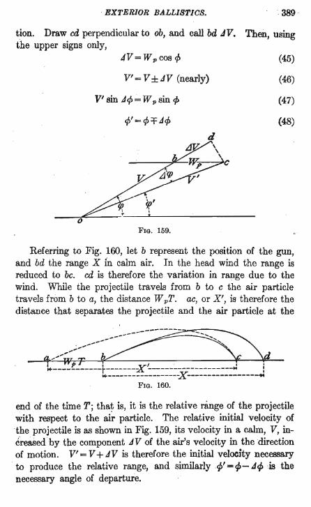
EXTERIOR BALLISTICS. , 389
tion. Draw cd perpendicular to ob, and call bd .dV. Then, using the upper signs only,
o
4V=Wpcos ~
V' = V ± JV (nearly)
V' sin J~~ W p sin p
d L1~ \
~~c ~v; • I
~ t
FIG. 159.
(45)
(46)
(47)
(48)
Referring to Fig. 160, let b represent the position of the gun, and bd the range X in calm air. In the head wind the range is reduced to bc. cd is therefore the variation in range due to the wind. While the projectile travels from b to c the air particle travels from b to a, the distance W pT. ac, or X', is therefore the distance that separates the projectile and the air particle at the
end of the time T; that is, it is the relative range of the projectile with respect to the ai~ particle. The relative initial velocity of the projectile is as shown in Fig. 159, its velocity in a cairn, V, inereased by the component J V of the air's velocity in the direction of motion. V' = V + JV is therefore the initial velocity necessary to produce the relative range, and similarly 4/ = 4>- J 4> cis the necessary angle of departure.
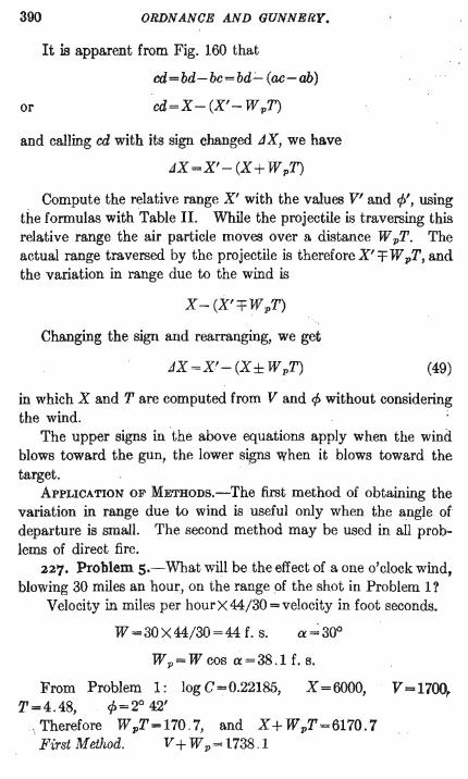
390
or
ORDNANCE AND GUNNERY.
It is apparent from Fig. 160 that
cd=bd-bc=bd~ (ac-ab)
cd=X-(X'- WpT)
and calling cd with its sign changed JX, we have
JX=X'- (X+ WpT)
Compute the relative range X' with the values V' and 1>', using the formulas with Table II. While the projectile is traversing this relative range the air particle moves over a distance W pT. The actual range traversed by the projectile is therefore X' =F W pT, and the variation in range due to the wind is
X- (X' TWpT)
Changing the sign and rearranging, we get
JX =X'- (X± WpT) (49)
in which X and T are computed from V and 1> without considering the wind.
The upper signs in the above equations apply when the wind blows toward the gun, the lower signs When it blows toward the target.
ApPLICATION OF METHoDs.-The first method of obtaining the variation in range due to wind is useful only when the angle of departure is small. The second method may be used in all problems of direct fire.
227. Problem s.-What will be the effect of a one o'clock wind, blowing 30 miles an hour, on the range of the shot in Problem 1?
Velocity in miles per hourX 44/30 = velocity in foot seconds.
W =30 X 44/30 =44 f. s.
W p = W cos ex = 38.1 f. s.
From Problem 1: log C = 0.22185, X = 6000, V = 1700, T=4.48, 1>=20 42'
, Therefore W pT=170.7, and X+WpT=6170.7 First Method. V + W p = 1738 . 1
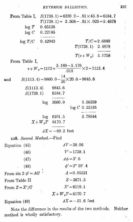
EXTERIOR BALLISTICS.
From Table I, 8(1738.1)=6220 .2- .81x43.8=6184.7 T(1738.1)= 2.508- .81X .025=2.4878 .
log TO . 65128 log CO . 22185
log T /C 0.42943 T/C=2.6880 T(1738.1) 2.4878
T(v+ W p) 5.1758 From Table I,
5.189-5.176 v+ W p=1112+ .018 X2=1113.4:
and 14
8(1113.4) =9860 .0-20 X20. 6 =9845.6
8(1113.4) 9845.6 8(1738.1) 6184.7
log 3660.9
log 6101.5 X+ WpT 6170.7
3.56359 log C 0 .22185
3.78544
JX = -69.2 feet
228. 8econd Method.-Find
Equation (45)
(46)
(47)
(48) , From sin 2 </>' = AC )
From Table II
From Z=X'/C
Equation (49)
.JV =38.06
V'=1738.1
.J</> = 3'.6
</>' = 2° 38' . 4
A=0.05521
Z=3671.5
X' =6119.1
X + W pT = 6170.7
.JX = -51.6 feet
391'
Note the difference in the results of the two methods. Neither method is wholly satisfactory.
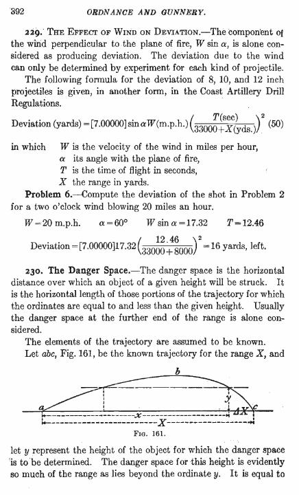
ORDN ANCE AND GUNNERY.
229. THE EFFECT OF WIND ON DEVIATION.-The component Of the wiiid perpendicular to the plane of fire, W sin a, is alone considered as producing deviation. The deviation due to the wind can only be determined by experiment for each kind of projectile.
The following formula for the deviation of 8, 10, and 12 inch projectiles is given, in another form, in the Coast Artillery Drill Regulations.
Deviation (yards) =[7.00000]sinaW(m.p.h.) (3300~:~?YdS.)r (50)
in which W is the velocity of the wind in miles per hour, a its angle with the plane of fire, T is the time of flight in seconds, X the range in yards.
Problem 6.-Compute the deviation of the shot in Problem 2 for a two o'clock wind blowing 20 miles an hour.
W =20 m.p.h. a =600 W sin a =17.32 T=12.46
Deviation = [7.00000]17.32 C30~~ :~OOO) 2 = 16 yards, left.
230. The Danger Space.-The danger space is the horizontal distance over which an object of a given height will be struck. It is the horizontal length of those portions of the trajectory for which the ordinates are equal to and less than the given height. Usually the danger space at the further end of the range is alone considered.
The elements of the trajectory are assumed to be known. Let abc, Fig. 161, be the known trajectory for the range X, and
b
let y represent the height of the object for which the danger space 'is to 'be determined. The danger space for this height is evidently so much of the range as lies beyond the ordinate y. It is equal to
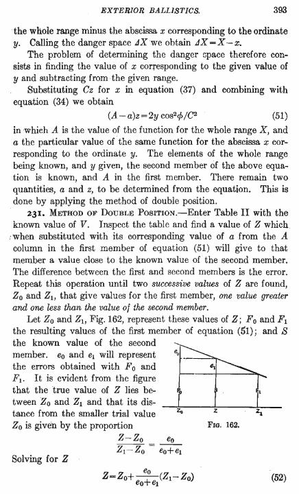
EXTERIOR BALLISTICS. 393
the whole range minus the abscissa x corresponding to the ordinate y. Calling the danger space JXwe obtain JX =X -x.
The problem of determining the danger Gpace therefore consists in finding the value of x corresponding to the given value of y and subtracting from the given range.
Substituting Cz for x in equation (37) and combining with equation (34) we obtain
(A-a)z=2y cOS2r/>/C2 (51)
in which A is the value of the function for the whole range X, and a the particular value of the same function for the abscissa x corresponding to the ordinate y. The elements of the whole range being known, and y given, the second member of the above equation is known, and A in the first member. There remain two quantities, a and z, to be determined from the equation. This is done by applying the method of double position.
231. METHOD OF DOUBLE POSITION.-Enter Table II with the known value of V. Inspect the table and find a value of Z which .
: when substituted with its corresponding value of a from the A column in the first member of equation (51) will give to that member a value close to the known value of the second member. The difference between the first and second members is the error. Repeat this operation until two successive values of Z are found, Zo and Zl, that give values for the first member, one value greater and one less than the value of the second member.
Let Zo and Zl, Fig. 162, represent these values of Z; F 0 and F1 the resulting values of the first member of equation (51); and S the known value of the second member. eo and e1 will represent the errors obtained with F 0 and Fl. It is evident from the figure that the true value of Z lies between Zo and Zl and that its distance from the smaller trial value Zo is given by the proportion
Z-Zo eo
Solving for Z Z1- Z0 = eO+e1
z
FIG. 162.
(52)
394 ORDNANCE AND GUNNERY.
In the application of this method to equation (51) we are assuming that (A-a)z varies proportionately with z between the values Zo and Zl. This is not a true assumption, but the results are sufficiently approximate for practical use.
To make this demonstration general we may consider that z and (A-a) in equation. (51) represent any two functions, f and f, whose product is known. We then have
If=k
We may write either f or f for Z in equation (52) and obtain the general formula
eo /=10+ eo+e/h-1o) (53)
We may now, employing the method of double position, determine from equation (52) the value of z in (51), and from the equation z=xjC we obtain the value of x corresponding to the given ordinate y. We then have for the danger space
tiX=X-x (54)
232. Problem 7.-What is the danger space, for an infantryman, in the 1000 yard trajectory of the service 0.30 caliber rifle; muzzle velocity, 2700 f. s.; bullet, 150 grains?
This assumes that the rifle is fired from the ground. The height of a man is assumed at 5' 8" =5.67 feet=y. The value of the coefficient of forme, in the ballistic coefficient,
as determined by experiment for the 150 grain bullet is e=O.5694, see foot-note.
w=150j7000 d=O.3 V=2700 X=3000
The coefficient of form is determined for the small arms bullet by means of actual measurements of the velocity. of the bullet at the ends of a long range, as, for instance, 500 yards. With the measured values of V and v, the latter corrected for the effect of wind if· there is any, and the measured range, the value of C is determined from the equation x=CIS(v)-S(V)1 by means of b.1llistic Table I. The coefficient of form c is then obtained from the equation
c=1~ a cd'
For the projectiles of large guns the coefficient c is determined by means of measured values of <P, V, and X, see Problem 12.

EXTERIOR BALLISTICS.
The steps in the operation are indicated as follows:
C=w/cd2 Z-=X/C Table II, A sin 2 cp=Aa (A-a)z=2y cos2cp/C2 x=zC ,;IX =X-x
C=w/cd2 log 7000 3.84510
z=x/a
log c i . 75542 log d2 2 .95424
2.55476 log 150 2 . 17609
log C i .62133 log X 3.47712
395
log Z 3 .85579 Z=7174.5 Table H, A= (0.06201)+0. 745 X 158=0.063187 sin 2 cp=AC log A 2.80063
log C i . 62133
log sin 2 cp 2.42196
(A-a)z=2y cOS2cp/C2 log 2y 1.05461 log cos2 cp i . 99992
1 05453 log C2 i .24266
2 cp= 10 30'.8 cp=45'.4
1.81187 (A-a)z=64.844
Applying the method of double position to find the values of z and a that will satisfy this equation, we find by inspection of Table II for V = 2700 that the value of Z = 6500 with the corresponding value of A, 0.05307, will when substituted in the last equation give a close approximation to 64.844.
With Z = 6500 we obtain
(0.063187 - 0.05307)6500 = 65.761
eo == 65.761- 64.844 =0.917
With Z=6600 (0.063187 - 0.05449)6600 = 57.4
el =64.844-5704=7.444

.896 ORDNANCE AND GUNNERY.
The results obtained with these values of Z are greater and less than 64.844.
eo Then from Z=Zo+-+ (Zl-ZO)
eo el
0.917 z=6500+ 0 . 917+7 .444 X 100 =-6511
x=zG log z 3.81365 log C i . 62133
log x 3 .43498 x=2722.6
JX=X-x JX =3000-2722.6=277.4 ft. =92.5 yds.
For V = 2700 we will also find that the value Z = 1122.7 with the corresponding value of a will nearly satisfy the equation (A-a)z=64.844. This value of z gives x=469.5 feet, which is at once the danger space at the inner end of the trajectory, see Fig. 161.
; 233. The Danger Range.-When the danger space is continuous and coincides with the range it is called the danger range. Thus the danger range for an infantryman is the range at every point of which an infantryman would be struck. The maximum ordinate of the trajectory is therefore 5 feet 8 inches.
To determine the danger range we compute the horizontal trajectory whose maximum ordinate Yo is given.
Combining equations (34) and (39) and making cos p unity, since p for all danger ranges is very small, we obtain
ao' ao" = 2Yo/C2 (55)
FrOm this we determine ao' by trial by the method of double position, using the A' and A" columns of Table II. Since at the summit ao' =A, see (38), with this value of ao' we go to the A column of Table II for the given value of V and find the corresponding value of Z, from which the required X is obtained.
234. Problem 8.-What is the danger range, for a cavalryman, of the service rifle fired from the ground? The height of a, cavalryman is assumed as 8 feet.
V =2700 log C= 1.62133 yo=8
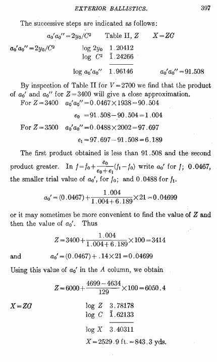
EXTERIOR BALLISTICS.
The successive steps are indicated as foHows:
log 2yo log C2
Table II, Z
1 .20412 1 .24266 -
x=za
397
log ao'ao" 1.96146 ao' ao" = 91.508
By inspection of Table II for V = 2700 we find that the product of ao' and ao" for Z = 3400 will give a close approximation.
For Z = 3400 ao' ao" = 0 . 0467 X 1938 = 90 . 504
eo =91.508-90.504= 1.004
For Z = 3500 ao' ao" = 0 . 0488 X 2002 = 97 . 697
el =97.697-91.508=6.189
The first product obtained is less than 91.508 and the second
product greater. In 1=/0+ e+o (ft-Io) write ao' for I; 0.0467,
eo el the smaller trial value of ao', for 10; and 0.0488tfor h.
'(0 ) 1.004 ao = .0467 +1.004+6.189X21 =0.04699
or it may sometimes be more convenient to find the value of Z and then the value of ao'. Thus
1 .004 Z =3400+ 1.004+6.189XlOO=3414
and ao'=(0.0467)+ .14X21 =0.04699
Using this value of ao' in the A column, we obtain
4699-4634 Z=6000+ 129 X 100=6050.4
x=za log Z 3.78178 log C 1.62133
log X 3.40311
X =2529. 9 ft. =843 .3 yds.
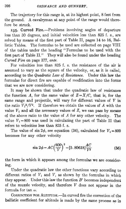
398 ORDNANCE AND GUNNERY.
The trajectory for this range is, at its highest point, 8 feet from the ground. A cavalryman at any point of the range would therefore be struck.
235. Curved Fire.-Problems involving angles of departure less than 30 degrees, and initial velocities less than 825 f. s., are solved by means of the first part of Table II, pages 14 to 16, Ballistic Tables. The formulas to ~e used are collected on page VIII of the tables under the heading I' Formulas to be used with the first part of Table II." They will also be found under the heading Curved Fire on page 377, ante.
For velocities less than 825 f. s. the resistance of the air is assumed to vary as the square of the velocity, or, as it is called, according to the Quadratic Law of Resistance. Under this law the fonnulas for direct fire are capable of modification into the forms that we are now considering.
It may be shown that under the quadratic law of resistance the function A, for the same value" of Z =X/C, that is, for tqe same range and projectile, will vary for different values of V ill the ratio VI2/V2. If therefore we obtain the values of A with the value VI and all the necessary values of Z, we can pass by means of the above ratio to the value of A for any other velocity. The value VI = 800 was used in calculating the part of Table II that referS to velocities less than 825 f. s.
The value of sin 21>, see equation (34), calculated for VI =800 becomes for any other velocity
. (800)2 AC sm 21>=AC V =[5.80618] V2 (56)
the form in which it appears among the formulas we are considering.
Under the quadratic law the other functions vary according to different ratios of VI and V, as shown by the formulas in " which they appear. Under this law the function B' becomes independent of the muzzle velocity, and therefore V does not appear in the formula for tan w.
CORRECTION FOR ALTITuDE.-In curved fire the correction of thE: ballistic coefficient for altitude is made by the same process as in
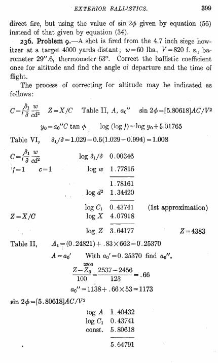
EXTERIOR BALLISTICS. 399
direct fire, but using the value of sin 21> given by equation (56) instead of that given by equation (34).
236. Problem 9.-A shot is fired from the 4.7 inch siege howitzer at a target 4000 yards distant; w=60 lbs., V =820 f. s., barometer 29".6, thermometer 63°. Correct the ballistic coefficient once for altitude and find the angle of departure and the time of flight.
The process of correcting for altitude may be indicated as follows:
c=l; C~2 Z=XjC Table II, A, ao" sin 21> = [5.80618]ACjV2
Yo= ao"C tan 1> log (log f) =log Yo+5.01765
Table VI, (\j 0' = 1.029 - 0.6(1.029 - 0:994) = 1.008
C =10'1 .:!!!... 0' cd2
'1=1 c=l
log O'dO'
log w
log d2
0;00346
1.77815
1.78161 1.34420
log C1 0.43741 (1st approximation) Z=XjG log X 4 .07918
log Z 3.64177
Table II, Al =(0.24821)+ .83X662=0.25370
A=ao' With ao' = 0 . 25370 find ao". 2200
Z-Zo =2537-2456 = 66 100 123 . .
ao" = 1138+ . 66 X 53 = 1173
Bin 21>=[5.80618]ACJV2
log A 1.40432 log C1 0.43741 const. 5 .80618
5 .64791
Z=4383
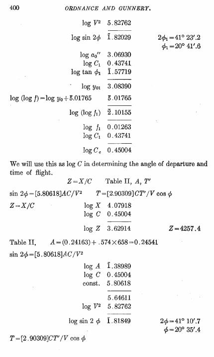
400 ORDNANCE AND GUNNERY.
log V2 5.82762 - -
log sin 2<p 1 .82029 2<Pi = 410 23'.2 <Pi =200 41'.6
log ao" 3 .06930 logC1 0.43741
log tan <P1 1 .57719
log YOl 3.08390
log (log I) =log Yo+ 0.01765 0.01765
log (log It) 2 .10155
log h 0.01263 log C1 0 .43741
log Cc 0.45004
We will use this as log C in determining the angle of departure and time of flight.
Z=XIC Table II, A, T'
sin 2<p = [5.80618]AC /V2
Z=XIC
T=[2.90309]CT'IV cos <p
log X 4 .07918 log CO . 45004
log Z 3.62914
Table II, A=(0 .24163)+ . 574X658=0.24541
sin 2<p=[5.80618]ACIV2
log A 1 .38989 log CO. 45004 const. 5.80618
5.64611 log V2 5 .82762
log sin 2 <p 1 . 81849
T =[2. 90309]CT' IV cos <p
Z=4257.4
2<p=41° 10'.7 <p = 200 35'.4
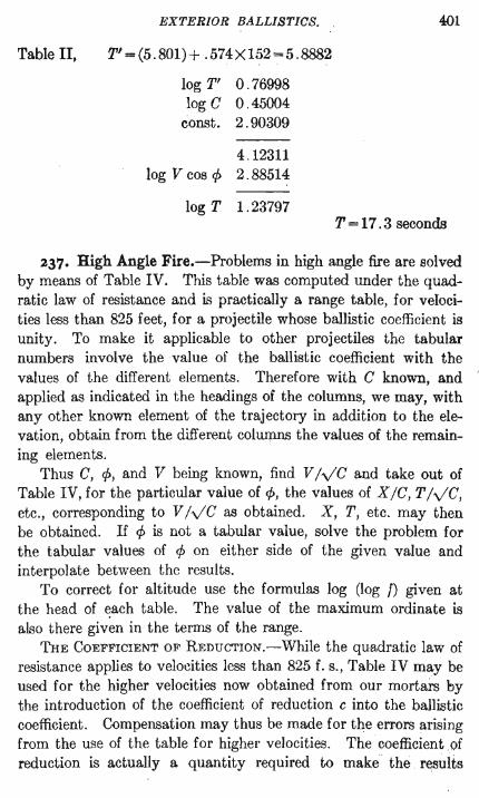
Table II,
EXTERIOR BALLISTICS.
T'=(5.801)+ .574X152=5.8882
log T' 0 . 76998 log CO. 45004
const. 2.90309
4.12311 log V cos P 2.88514
log T 1 .23797
401
T=17.3 seconds
237. High Angle Fire.-Problems in high angle fire are solved by means of Table IV. This table was computed under the quadratic law of resistance and is practically a range table, for velocities less than 825 feet, for a projectile whose ballistic coefficient is unity. To make it applicable to other projectiles the tabular numbers involve the value of the ballistic coefficient with the values of the different elements. Therefore with C known, and applied as indicated in the headings of the columns, we may, with any other known element of the trajectory in addition to the elevation, obtain from the different columns the values of the remaining elements.
Thus C, p, and V being known, find V IvC and take out of Table IV, for the particular value of p, the values of XIC, T IvC, etc., corresponding to V IvC as obtained. X, T, etc. may then be obtained. If p is not a tabular value, solve the problem for the tabular values of p on either side of the given value and interpolate between the results.
To correct for altitude use the formulas log (log f) given at the head of each table. The value of the maximum ordinate is also there given in the terms of the range.
THE COEFFICIENT OF REDUCTION.-While the quadratic law of resistance applies to veloeities less than 825 f. s., Table IV may be used for the higher velocities now obtained from our mortars by the introduction of the coefficient of reduction c into the ballistic coefficient. Compensation may thus be made for the errors arising from the use of the table for higher velocities. The coefficient of reduction is actually a quantity required to make the results
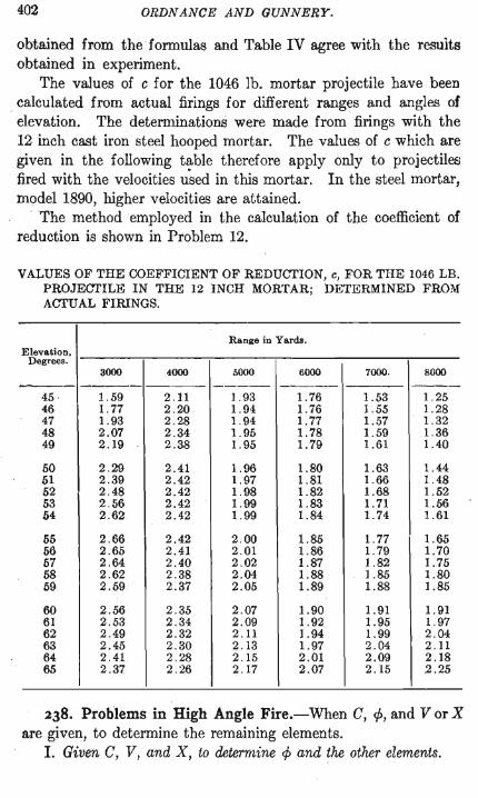
402 ORDNANCE AND GUNNERY.
obtained from theformulas and Table IV agree with the results obtained in experiment.
The values of c for the 1046 lb. mortar projectile have been calculated from actual firings for different ranges and angles of elevation. The detemlinations were made from firings with the 12 inch cast iron steel hooped mortar. The values of c which are given in the following table therefore apply only to projectiles fired with the velocities u~ed in this mortar. In the steel mortar, model 1890, higher velocities are attained.
The method employed in the calculation of the coefficient of reduction is shown in Problem 12.
VALUES OF THE COEFFICIENT OF REDUCTION, c, FOR THE 1046 LB. PROJEaI'ILE IN THE 12 INCH MORTAR; DETERMINED FROM AaI'UAL FIRINGS.
Range in Yards. Elevation,
Degrees. 3000 4000 5000 6000 7000. 8000
--- - -------- ----- ---- ---- ._- --45 1.59 2 . 11 1.93 1.76 1.53 1.25 46 1.77 2.20 1.94 1. 76 1.55 1.28 47 1.93 2.28 1.94 1. 77 1.57 1.32 48 2.07 2 .34 1.95 1. 78 1.59 1.36 49 2.19 2.38 1.95 1.79 1.61 1.40
50 2 .29 2.41 1.96 1.80 1.6.1 1.44 51 2.39 2.42 1.97 1.81 1.66 1.48 52 2.48 2.42 1.98 1.82 1.68 1.52 53 2 .56 2.42 1.99 1.83 1.71 1.56 54 2.62 2.42 1.99 1.84 1. 74 1.61
55 2.66 2.42 2.00 1.85 1.77 1.65 56 2 .65 2.41 2.01 1.86 1. 79 1. 70 57 2.64 2.40 2.02 1.87 1.82 1. 75 58 2 .62 2.38 2 .04 1.88 1.85 1.80 59 2.59 . 2.37 2.05 1.89 1.88 1.85
60 2 .56 2.35 2.07 1.90 1.91 1.91 61 2 .53 2.34 2.09 1.92 1.95 1.97 62 2.49 2.32 2 . 11 1.94 1.99 2.04 63 2.45 2.30 2.13 1.97 2.04 2.11 64 2.41 2.28 2.15 2.01 2.09 2.18 65 2 .37 2 .26 2.17 2.07 2.15 2.25
238. Problems in High Angle Fire.-When C, 1>, and Vor X a.re given, to determine the remaining elements.
1. Given C, V, and X, to determine 1> and the other elements.
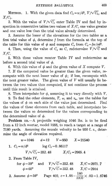
EXTERIOR BALLISTICS. 403
METHOD. 1. With the given data find C1 =w/ d2, V /VC1, · and X /C1 •
2. With the value of V Ive1 enter Table IV and find by inspection.in consecutive tables two values of X IC, one value greater and one value less than the trial value already determined.
3. Assume the lesser of the elevations for the two tables as a first trial value of ¢, determine f from. the formula at the top of the table for this value of ¢ and compute Cc from Cc =fwlcd2•
4. Then, using the value of Cc as C, redetermine V Ive and X/C.
5. With these values reenter Table IV and redetermine as before a second trial value of ¢.
6. With this value of ¢ and the given value of X compute V. 7. If the computed value be greater than the given value, re
compute with the next lesser value of ¢; if less, recompute with the next greater value. The given value of V will usually lie between the two values thus computed, if not continue the process • until this result is attained .
. 8. Then interpolate for ¢, assuming it to vary directly with V. 9. To find the other elements, T, UJ, and v .. , use the tables for
the values of ¢ on each side of the value just determined. Find the values of these elements from each table, and interpolate between the values so determined for the values corresponding to the determined value of ¢.
Problem Io.-A projectile weighing 1046 lbs. is to be fired from a 12 inch mortar, model 1888, to reach a target at a range of 7180 yards. Assuming the muzzle velocity to be 950 f. s., determine the angle of elevation required.
w=1046 d=12 V =950 X=21540
1. C1 =w/d2 log C1 =0.86117
V /va;, =352.48 X/C1 =2965 .4
2. From Table IV,
for ¢=59° ¢=600
3. Assume ¢ = 59°
and V/vC=352.48 X/C=2971.7 V /vC =352.48 XIC =2914
. 180 Page 402, c= 1.88-
1000 X .03=1.8746
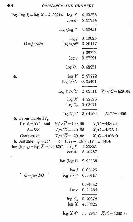
404 ORDNANCE AND GUNNERY.
log (log I) = log X -5.32914 log X 4.33325 const. 5.32914
log (log f) 1.00411
log 1 0.10095 G=lw/d2c log w/d2 0.86117
0.96212 log c 0.27291
--log Cc 0.68921
---4. log V 2.97772
log vc;, 0.34461 ---
log V/VC 2.63311 V/VC=429.65
log X 4.33325 log Cc 0.68921
----log X/C '3.64404 X/C=4406
5. From Table IV, for 1>=55° and V/VC=429.65 X/C=4436.1
1>=56° V/VC=429 .65 X/C=4375.1 Computed V/VC=429.65 X/C=4406.0
6. Assume 1>=55° c= 1. 77 - .18X .12 = 1. 7484 log (log I) = log X - 5 .40257 log X 4.33325
const. 5.40257 ---
log (log f) 2.93068
log 1 0.08525 c=fw/d2a log w/d2 0.86117
0.94642 log c 0 .24264
--log Cc 0.70378 log X 4.33325
log X/C 3.62947 X/C=4260.o
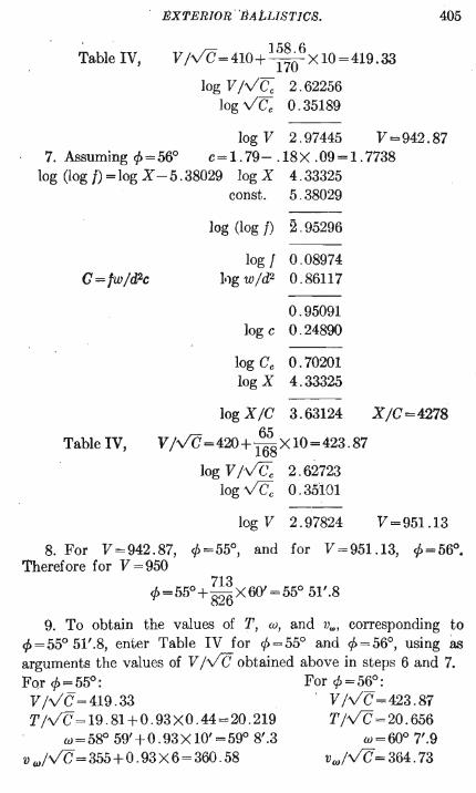
EXTERIOR· BALLISTICS. 405
Table IV, . /ri 1,58.6
Vlv C=41O+ 170 XlO=419.33
log V Iv Cc 2.622,56 log vC; 0.35189
log V 2.97445 V=942.87 7. Assuming 4>=56° c=1.79- .18X .09=1.7738
log (log I) = log X - 5.38029 log X 4.33325
C=/w/d2c
const. 5 .38029
log (log f) 2 .95296
log 1 0.08974 l')g wld2 0.86117
0.95091 log cO. 24800
log Ce 0.70201 log X 4.33325
log X IC 3.63124 X /e = 4278
Table IV, 65
V IVC=420+ 168X10=423.87
log V Ivc" 2 . 62723 log vCe 0.35101
log V 2.97824 V=951.13
8. For V=942.87, ¢=55°, and for V=951.13, ¢=56°. Therefore for V =950
4>=55°+ ~~:X60' =55° 51'.8
9. To obtain the values of T, w, and v"" corresponding to ¢=55° 51'.8, enter Table IV for ¢=55° and ¢=56°, using as arguments the values of V IVC obtained above in steps 6 and 7. For ¢=55°: For ¢=56°: VlvC=419.33 ' VIVC=423.87 T IVC = 19.81+0.93XO.44=20.219 T Ive =20.656
w=58° 59'+0.93XI0'=59° 8'.3 w=600 7'.9 v wlvC = 355 + 0 .93 X 6 = 360.58 vwlVC = 364.73
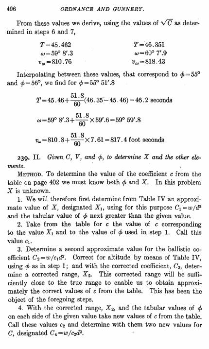
406 ORDNANCE AND GUNNERY.
From these values we derive, using the values of V C as deter~ mined in steps 6 and 7,
T=45.462 w=59° 8'.3
vw =810.76
T=46.351 w=600 7'.9
vw =818.43
Interpolating between these values, that correspond to c/> = 55° and c/> = 56°, we find for c/> = 55° 51'.8
T=45.46+ 5~8(46.35~45.46)=46.2 seconds
w=59° 8'.3+ 5~8X59'.6=59° 59'.8
51.8 f ds v .. =810.8+00X7.61=817.4 oot secon
239. II. Given C, V, and C/>, to determine X and the other elements.
METHOD. To determine the value of the coefficient c from the table on page 402 we must know both ¢ and X. In this problem X is unknown.
1. We will therefore first determine from Table IVan approximate value of X, designated Xl, using for this purpose Cl =w/d2 and the tabular value of c/> next greater than the given value.
2. Take from the table for c the value of c corresponding to the value Xl and to the value of ¢ used in step 1. Call this value Cl.
3. Determine a second approximate value for the ballistic coefficient C2 =W/c1d2• Correct for altitude by means of Table IV, using ¢ as in step 1; and with the corrected coefficient, C3, determine a corrected range, X 2. This corrected range will be sufficiently close to the true range to enable us to obtain approximately the correct values of c from the table. This has been the object of the foregoing steps.
4. With the corrected range, X 2, and the tabular values of ¢ on each side of the given value take new values of c from the table. Call these values C2 and determine with them two new values for C, designated C4 =W/c2d2•

EXTERIOR BALLISTICS. 407
5. By means of Table IV, for the values of ¢ on each side of the given value, correct both values of C4 for altitude. Call the resulting values C 5.
6. Using the values C 5 as C find the corresponding values of V /v C and then, from Table IV, the corresponding values of X and the other elements.
7. Interpolate between the values thus found for the values corresponding to the given value of ¢.
Problem n.-Assume d= 12 inches, ¢=55° 40'
Determine X, T, w, and VW '
w=1046Ibs. V =950 f. s.
1. C1 =w/d2 =[0. 86117] log V 2.97772
log V C1 0.43059
log V /vC1 2.54713 V /VCI ~352.48
With this value we find from Table IV, for ¢=56°,
X/CI =3084+ .25X156=3123 log X /C1 3.49457
log C1 0.86117
log Xl 4.35574 Xl =22685 ft. =7561.7 yds.
2. From the table of values of c, with X = 7562 yds.and ¢ = 56°,
C1 = 1. 79 - .562 X 0 .9= 1. 739
3. C2=W/c1d2=Ct/Cl =[0.62087] For use in Table IV, log V 2 .97772
log vC2 0.31044
log V/V'75; 2.66728 V/vC2=464.81
From Table IV, for ¢=56°,
X/C2=4890+ .48 X 173 =4973 log X/C2 3.69662
log C2 0.62087
log X 4.31749
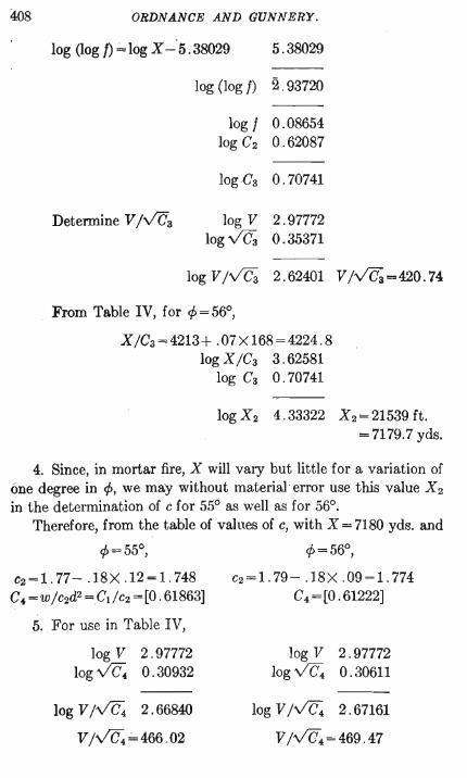
408 ORDNANCE AND GUNNERY.
log (log f) = log X -·5.38029 5.38029
Determine V /VC3
log (log I) 2 . 93720
log 1 0 . 08654 log C2 0.62087
loge3 0.70741
log V 2 .97772 log va; 0 . 35371
log V /va; 2 .62401 V /va; = 420.74
From Table IV, for cp=56°,
X/Ca=4213+ .07XI68=4224.8 log X /Ca 3.62581
log Ca 0.70741
log X 2 4 .33322 X 2 =21539 ft. = 7179.7 yds.
4. Since, in mortar fire, X will vary but little for a variation of one degree in cp, we may without material · error use this value X 2
in the determination of c for 55° as well as for 56°. Therefore, from the table of values of c, with X = 7180 yds. and
cp=55°, cp=56°,
C2=1. 77- .18X .12=1. 748 C. =W /c2d2 =CdC2 =[0.61863]
5. For use in Table IV,
log V 2.97772 log ~ 0.30932
log V/vC4 2.66840
V/V(h';"466.02
C2 = 1. 79 - . 18 X .09 = 1. 774 C4 =[0.61222]
log V 2.97772 log ~ 0 . 30611
log V /vC4 2.67161
V/~=469.47
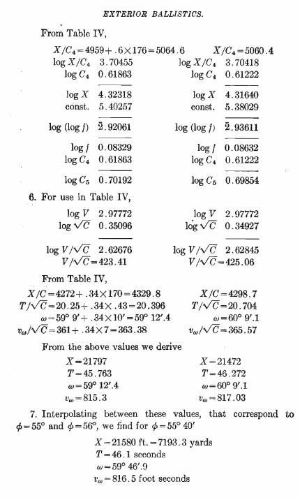
EXTERIOR BALLISTICS.
From Table IV,
XjC4 = 4959+ .6XI76=5064 .6 XjC4 =5060.4 log XjC4 3 .70455
logC4 0.61863 --
logX 4.32318 const. 5.40257
log (log f) 2.92061
log f 0.08329 log C4 0.61863
logCs 0.70192
6. For use in Table IV,
log V 2.97772 log VC 0.35096
log V JVC 2.62676 VjVC=423.41
From Table IV,
XjC=4272+ .34XI70=4329.8 TjVC=20.25+ .34X .43=20.396
w=59° 9'+ .34XI0'=5g0 12'.4 vw jvC=361+ .34X7=363.38
log XjC4 3.70418 logC4 0 .61222
log X 4.31640 canst. 5.38029
log (log f) 2.93611
log f 0.08632 logC4 0.61222
logCs 0.69854
log V 2.97772 lo'gVC 0.34927
log V JVC 2.62845 VjVC=425.06
XjC=4298.7 TjVC=20.704
w=600 9'.1 vw jVC=365.57
From the above values we derive
X =21797 X =21472 T=46.272 T=45.763
w=59° 12'.4 w=60° 9'.1 Vw =815 .3 vw =817 .03
409
7. Interpolating between these values, that correspond to 1>=55° and 1>=56°, we find for 1>=55° 40'
X =21580 ft.=7193.3 yards T = 46 . 1 seconds w=59° 46'.9
t·w = 816.5 foot seconds
410 ORDNANCE AND GUNNERY.
It will be seen that the approximate range, X 2 = 7179.7 yards, used in determining the vaJue of c, is very close to the true range, 7193.3 yards.
240. Calculation of the Coefficient of Reduction.-A recent addition. to Table IV, printed in the Journal 01 the United States Artillery, Jan.-Feb., 1905, provides a simple method of computing the coefficient of reduction for any projectile, when 1>, V, and X are determined from actual firings.
A column containing values of V2 IX, obtained by combining the two columns V Ive and XIC, is added to the table. With 1> and V21X as arguments, we may obtain C from the value in the column V)V C. The value of ' C thus obtained is the complete
a1 W value, C = I""'§ cd2' Determine 1 from the formula at the head of
the table, and ada from Table VI. c is then readily determined. When the additional column giving the values of V2 IX is not
at hand, the value of V Ive corresponding to any value of V2 IX may be readily determined from Table IV by trial. Square the values in the V IVC column and divide by the corresponding values in the X IC column until two values of V2 I X are found, one value greater and one less than the given value. By interpolation the value of V Iv C corresponding to the given value of V2 /X may then be found.
241. Problem I2.-The range of the 1046 lb. projectile from the 12 inch steel mortar, model 1890 MI, is limited to 11,215 yards. The muzzle velocity of the projectile is 1150 feet, the velocity being limited by the requirement that the maximum pressure shall not exceed 33,000 lbs. In order to extend the range of the mortar a projectile weighing 824 lbs. is provided, for which, without exceeding the allowed pressure, the muzzle velocity is increased to 1325 feet and the range to 12,713 yards.
Compute the value of the coefficient of reduction, c, for that projectile with the following data obtained in experiment.
d=12 w=824 V =1325 1>=45° X =38,139 feet Barometer, 30".5 Thermometer, 65° F.
The process of solution is indicated as follows:
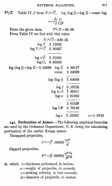
EXTERIOR BALLISTICS. 411
V2/X Table IV, C from V IVC, log (log f) = log X-const.log.
~1 w C=f"b Cd2
From the given data, V2/X =46.03 From Table IV we find with this value
VIVc=639.25 log V 3.12222
log V IVC 2.80567
logvC 0.31655 log Cc 0.63310
log (log /) = log X - 5.55099 log X 4.58137 const. 5.55099
log (log f) 1 .03038 ----
log f 0.10725 log ~di3 1.99211
logw 2.91593
3.01529 logCd2 2.79146
log e 0.22383 C= 1. 6743
242. Perforation of Armor.-The following empirical formulas are used by the Ordnance Department, U. S. Army, for calculating perforation of the earlier Krupp armor. .
Uncapped projectiles, wv2
t1•5 = [7.16459] d
Capped projectiles,
tOo7 = [4.84060] ~.:~ in which t = thickness perforated, in inches;
w=weight of projectile, in pounds; o = striking velocity, in foot seconds; d=diameter of projectile, in inches.
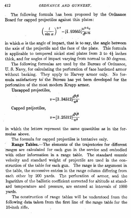
412 ORDNANCE AND GUNNERY.
The following formula has , been proposed by the Ordnance Board for capped projectiles against thin plates:
( t ) 0·7 , U;O·5V
-.- = [4 . 92665] -XI 75 sma 1";-'
in which a is the angle of impact, that is to say, the angle between the axis of the projectile and the face of the plate. This formula is applicable to tempered nickel steel plates from 3 to 41 inches thick, and for angles of impact varying from normal to 50 degrees.
The following formulas are used by the Bureau of Ordnance, U. S. Navy, for calculating the perforation of face hardened armor without backing. They apply to Harvey armor only. No formula satisfactory to' the' Bureau has yet been developed for the perforation of the most modem Krupp armor.
Uncapped projectiles,
Capped prdjectiles,
dill v = [3.34512) wi
ditl v = [3 .25312] wi
in which the letters represent the same quantities as in the formulas above.
The formula for capped projectiles is tentative only. Range Tables.~ The elements of the trajectories for different
'ranges are calculated for each gun in the service and embodied with other information in a range table. The standard muzzle velocity and standard weight of projectile are used in the construction of the table for each gun. The range is the argument in the table, the successive entries in the range column differing from each other by 200 yards. The perforation of armor" and the logarithm of the ballistic coefficient .corrected for altitude at standard temperature and pressure, are entered at intervals of 1000 yards.
The construction of range tables will be understood from the following data taken from the first line of the range table for the 10-inch rifle.
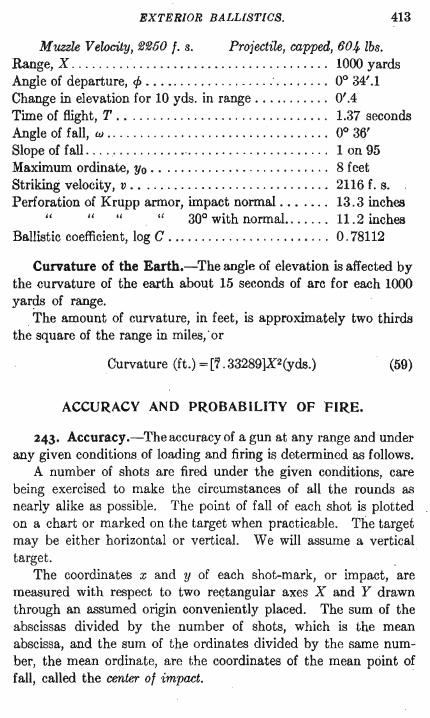
EXTERIOR BALLISTICS. 413
Muzzle Velocity, ~~50 f. s. Projectile, capped, 60"", lbs. Range, X .. ... . .. , ............ ... .............. 1000 yards Angle of departure, <p ••••...... ....•. .. : • • . • . . .• 00 34'.1 Change in elevation for 10 yds. in range. . . .. . . . . .. 0'.4 Time of flight, T . . . . . . . . . . . . . . . . . . . . . . . . . . . . . .. 1.37 seconds Angle of fall, w .. ...................... ' ......... 00 36' Slope of fall ............... -. . . . . . . . . . . . . . . . . . . .. 1 on 95 Maximum ordinate, Yo • • . . . . . . . . . . . . . . . . . . . . . . .. 8 feet Striking velocity, v . .......................... " 2116 f. s. Perforation of Krupp armor, impact normal .... '" 13.3 incheB
" ",' " 300 with normal.. . . . .. 11.2 incheB Ballistic coefficient, log C . .. . . . . . . . . . . . . . . . . . . . .. 0.78112
Curvature of the Earth.-The angle of elevation is affected by the curvature of the earth about 15 seconds of arc for each 1000 yards of range.
The amount of curvature, in feet, is approximately two thirds the square of the range in miles, . or
Curvature (ft.) = [7. 33289]X2(yds.) (59)
ACCURACY AND PROBABILITY OF FIRE.
243. Accuracy.-Theaccuracyof a gun at anyrange and under any given conditions of loading and firing is determined as follows.
A number of shots are fired under the given conditions, care being exercised to make the circumstances of all the rounds as nearly alike as possible. The point of fall of each shot is plotted on a chart or marked on the target when practicable. The target may be either horizontal or vertical. We will assume a vertical , target. .
The coordinates x and y of each shot-mark, or impact, are measured with respect to two rectangular axes X and Y drawn through an assumed origin conveniently placed. The sum of the abscissas divided by the number of shots, which is the mean abscissa, and the sum of the ordinates divided by the same number, the mean ordinate, are the coordinates of the mean point of fall, called the center of impact.
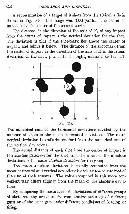
414 ORDN ANCE AND GUNNERY.
A representation of a target of 8 shots from the lO-inch rifle is shown in Fig. 163. The range was 3000 yards. The center of impact is at the center of the crossed circle.
The distance, in the direction of the axis of Y, of any impact from the center of impact is the vertical deviation for the shot. The deviation is plus if the shot-mark lies above the center of impact, and minus if below. The distance of the shot-mark from the center of impact in the direction of the axis of X is the lateral deviation of the shot, plus if to the right, minus if to the left.
FIG. 163.
The numerical sum of the horizontal deviations divided by the number of shots is the mean horizontal deviation. The mean vertical deviation is similarly obtained from the numerical sum of
, the vertical deviations. The actual distance of each shot from the center of impact is
the absolute deviation for the shot, and the mean of the absolute deviations is the mean absolute deviation for the group.
The mean absolute deviation is usually computed from the mean horizontal and vertical deviations by taking the square root of the sum of their squares. The value computed in this more convenient way differs slightly from the mean of the absolute deviations.
By comparing the mean absolute deviations of different groups of shots we may arrive at the comparative accuracy of different guns or of the same gun under different conditions of 16ading or fixing.
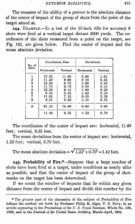
EXTERIOR BALLISTICS. 415
The measure of the ability of a gunner is the absolute distance of the center of impact of the group of shots from the point of the
. target aimed at. 244. EXAMPLE.-In a test of the lO-inch rifle for accuracy 8
shots were fired at a vertical target distant 3000 yards. The coordinates of the shots measured from a point on the target, see Fig. 163, are given below. Find the center of impact and the mean absolute deviation.
Coordinates, Feet. Deviations. No. of Shot.
Horizontal. Vertical. Horizontal. Vertical. ---
I 12.20 11.00 0.80 1.65 2 11.50 . 9.90 0.10 0.55 3 13.30 9.75 1.90 0 .40 4 11. 70 9.10 0.30 0.25 5 13.20 9.15 1.80 0.20 6 9.00 9.55 2.40 0.20 7 11.05 7.15 0.35 2.20 8 9.25 9.20 2.15 0.15
---8 91.20 74.80 9.80 5.60
----11.40 9.35 1.23 0.70
The coordinates of the center of impact are: horizontal, 11.40 feet; vertical, 9.35 feet.
The mean deviations from the center of impact are: horizontal; 1.23 feet; vertical, 0.70 feet.
The mean absolute deviation = J 1.232 +0.702 =1.42 feet.
245. Probability of Fire.*-Suppose that a large number of shots have been fired at a target, under conditions as nearly alike as possible, and that the center of impact of the group of shotmarks on the target has been determined.
If we count the number of impacts that lie within any given distance from the center of impact and divide this number by the
* The greater part of the discussion of the subject of Probability of Fire follows the method set forth by Professor Philip R. Alger, U. S. Navy, in an article appearing in the Proceeding8 of the U. S. Naval In8titute,Whole No. 108, 1903, and in the Journal of .the United States Artillery, March-April, 1904.
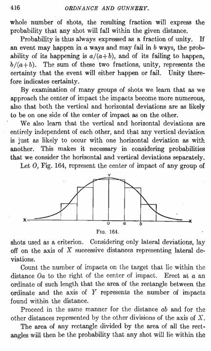
416 ORDNANCE AND GUNNERY.
whole number of shots, the resulting fraction will express the probability that any shot will fall within the given distance.
Probability is thus always expressed as a fraction of unity. If an event may happen in a ways and may fail in b ways, the probability of its happening is aj(a+b), and of its failing to happen, bj(a+b). The sum of these two fractions, unity, represents the certainty that the event will either happen or fail. Unity therefore indicates certainty.
By examination of many groups of shots we learn that as we approach the center of impact the impacts become more numerous, also that both the vertical and horizontal deviations are as likely to be on one side of the center of impact as on the other.
We also learn that the vertical and horizontal deviations are entirely independent of each other, and that any vertical deviation is just as likely to occur with one horizontal deviation as with another. This makes it necessary in considering probabilities that we consider the horizontal and vertical deviations separately.
Let 0, Fig. 164, represent the center of impact of any group of v
FIG. 164.
shots used as a criterion. Considering only lateral deviations, lay off on the axis of X successive distances representing lateral deviations.
Count the number of impacts on the target that lie within the distance Oa to the right of the center of impact. Erect at a an ordinate of such length that the area of the rectangle between the ordinate and the axis of Y represents the number of impacts found within the distance.
Proceed in the same manner for the distance ab and for the other distances represented by the other divisions of the axis of X.
The area of any rectangle divided by the area of all the rectangles will then be the probability that any shot will lie within the
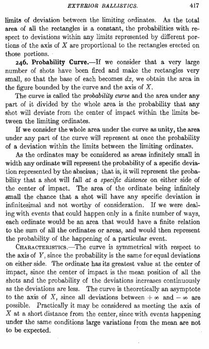
EXTERIOR BALLISTICS. 417
limite of deviation between the limiting ordinates. As the total area of all the rectangles is a constant, the probabilities with respect to deviations within any limits represented by different portions of the axis of X are proportional to the rectangles erected on those portions. . .
246. Probability Curve.-If we consider that a very large number of shots have been fired and make the rectangles very small, so that the base of each becomes dx, we obtain the area in the figure bounded by the curve and the axis of X.
The curve is called the probability curve and the area under any part of it divided by the whole area is the probability that any shot will deviate from the center of impact within the limits between the limiting ordinates.
If we consider the whole area under the curve as unity, the area under any part of the curve will represent at once the probability of a deviation within the limits between the limiting ordinates.
As the ordinates may be considered as areas infinitely small in width any ordinate will represent the probability of a specific deviation represented by the abscissa; that is, it will represent the probability that a shot will fall at a specific distance on either side of the center of impact. The area of the ordinate being infinitely small the chance that a shot will have any specific deviation is infinitesimal and not worthy of consideration. If we were dealing with events that could happen only in a finite number of ways, each ordinate would be an area that would have a finite relation to the sum of all the ordinates or areas, and would then represent the probability of the happening of a particular event.
CHARACTERISTlcs.-The curve is symmetrical with respect to the axis of Y, since the probability is the same for equal deviations on either side. The ordinate has its greatest value at the center of impact, since the center of impact is the mean position of all the shots and the probability of the deviations increases continuously as the deviations are less. The curve is theoretically an asymptote to the axis of X, since all deviations between + 00 and - 00 are possible. Practically it may be considered as meeting the axis of X at a short distance from the center, since with events happening under the same conditions large variations from the mean are not to be expected. ' .
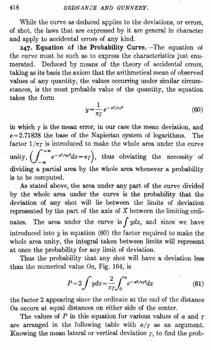
418 ORDNANCE AND GUNNERY.
While the curve as deduced applies to the deviations, or errorS, of shot, the laws that are expressed by it are general in character and apply to accidental errors of any kind.
247. Equation of the Probability Curve.-The equation of the curve must be such as to express the characteristics just enumerated. Deduced by means of the theory of accidental errors, taking as its basis the axiom that the arithmetical mean of observed values of any quantity, the values occurring under similar circumstances, is the most probable value of the quantity, the equation takes the form
1 Y=_ e- x2/".,. 7rT
(60)
in which T is the mean error, in our case the mean deviation, and e=2.71828 the base of the Napierian system of logarithms. The factor 1/7rT is introduced to make the whole area under the curve
unity, (1:«Je-x2/"r2dX=7rT), thus obviating the necessity of
dividing a partial area by the whole area whenever a probability is to be computed.
As stated above, the area under any part of the .curve divided by the whole area under the curve is the probability that the deviation of any shot will lie between the limits of deviation represented by the part of the axis of X between the limiting ordi-
nates. . The area under the curve is f ydx, and since we have
introduced into y in equation (60) the factor required to make the whole area unity, the integral taken between limits will represent at once the probability for any limit of deviation.
Thus the probability that any shot will have a deviation less than the numerical value Oa, Fig. 164, is
(61)
the factor 2 appearing since the ordinate at the end of the distance Oa occurs at equal distances on either side of the center.
The values of P in this equation for various values of a and T are arranged in the following table with alT as an argument. Knowing the mean lateral or vertical deviation T, to find the prob-
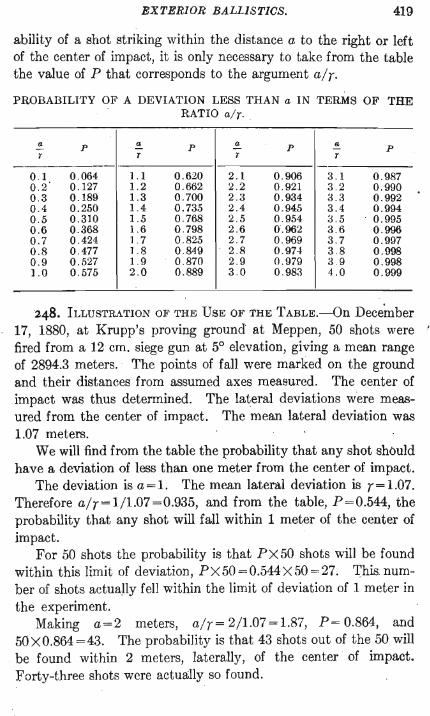
EXTERIOR BALLISTICS. 419
ability of a shot striking within the distance a to the right or left of the center of impact, it is only necessary to take from the table the value of P that corresponds to the argument air. PROBABILITY OF A DEVIATION LESS THAN a IN TERMS OF THE
RATIO air.
!!.- p !!.- p !!.- p ~ p r r r T
-------._-----0 .1 0.064 l.1 0.620 2 .1 0.906 3.1 0 .987 0.2 0.127 l.2 0.662 2.2 0.921 3.2 0 .990 0.3 0.189 l.3 0.700 2.3 0.934 3.3 0.992 0.4 0.2.'>0 l.4 0.73.5 2.4 0.94.'> 3.4 0.994 0 . .'> 0.310 l..'> 0.768 2 . .'> 0.9.'>4 3 . .'> 0.99.'> 0.6 0 .368 l.6 0 .798 2 .6 0.962 3.6 0.996 0.7 0.424 1.7 0.82.'> 2.7 0.969 3.7 0.997 0.8 0.477 1.8 0.849 2.8 0.97-1 3.8 0.998 0.9 0 . .'>27 l.9 0.870 2.9 0 .979 3.9 0.998 1.0 0 . .'>7.'> 2.0 0.889 3.0 0.983 4.0 0.999
248. ILLUSTRATION OF THE USE OF THE TABLE.-On Decernber 17, 1880, at Krupp's proving ground at Meppen, 50 shots were • fired from a 12 cm. siege gun at 5° elevation, giving a mean range of 2894.3 meters. The points of fall were marked on the ground and their distances from assumed axes measured. The center of impact was thus determined. The lateral deviations were measured from the center of impact. The mean lateral deviation was 1.07 meters.
We will find from the table the probability that any shot should have a deviation of less than one meter from the center of impact.
The deviation is a = 1. The mean lateral deviation is r = 1.07. Therefore a/r=1/1.07=0.935, and from the table, P=0.544, the probability that any shot will fall within 1 meter of the center of impact.
For 50 shots the probability is that PX50 shots will be found within this limit of deviation, PX50=0.544X50=27. This number of shots actua~ly fell within the limit of deviation of 1 meter in the experiment.
Making a=2 meters, a/r=2/1.07=1.87, P=0.864, and 50 X 0.864 = 43. The probability is that 43 shots out of the 50 will
. be found within 2 meters, laterally, of the center of impact. Forty-three shots were actually so found.
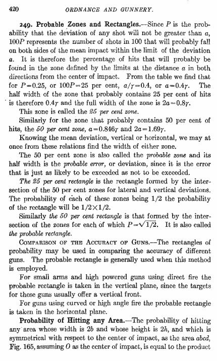
420 ORDNANCE AND GUNNERY.
249. Probable Zones and Rectangles.-Since P is the probability that the de~iation of any shot will not be greater than a, lOOP represents the number of shots in 100 that will probably fall on both sides of the mean impact within the limit of the deviation a. It is therefore the percentage of hits that will probably be found in the zone defined by the limits at the distance a in both directions from the center of impact. From the table we find that for P=0.25, or 100P=25 per cent, a/r=O.4, or a=0.4r. The half width of the zone that probably contains 25 per cent of hits
. is therefore OAr and the full width of the zone is 2a=0.8r. This zone is called the 925 per cent zone. Similarly for the zone that probably contains 50 per cent of
hits, the 50 per cent zone, a=0.846r and 2a=1.69r. Knowing the mean deviation, vertical or horizontal, we may at
once from these relations find the width of either zone. The 50 per cent zone is also called the probable zone and its
half width is the probable error, or deviation, since it is the error that is just as likely to be exceeded as not to be exceeded.
The 925 per cent rectangle is the rectangle formed by the intersection of the 50 per cent zones for lateral and vertical deviations. The probability of each of these zones being 1/2 the probability of the rectangle will be 1/2Xl/2.
Similarly the 50 per cent rectangle is that formed by the intersection of the zones for each of which P=V1/2. It is also called the probable rectangle.
COMPARISON OF THE ACCURACY OF GUNs.-The rectangles of probability may be used in comparing the accuracy of different guns. The probable rectangle is generally used when this method is employed.
For small arms and high powered guns using direct fire the probable rectangle is taken in the vertical plane, since the targets for these guns usually offer a vertical front.
For guns using curved or high angle fire the probable rectangle is taken in the horizontal plane.
Probability of Hitting any Area.-The probability of hitting any area whose width is 2b and whose height is 2h, and which is symmetrical with respect to the center of impact, as the area abed, Fig. 165, assuming 0 as the center of impact, is equal to the product

.EXTERIOR BALLISTICS. 421
of the two values of P taken from the table with biT", and hiT" as arguments, the subscripts indicating lateral and vertical deviations.
If the center of impact lies in the given area, or on its edge, the proba- f bility of hitting the area is readily obtained by dividing the area into parts a
by lines passing through the center of impact and taking the sum of the probabilities of hitting the parts.
Thus the probability of hitting the area efgh, Fig. 165, is the sum of the e
probabilities of hitting the four rect- d
angles into which it is divided by lines through the center of impact. The
0
g
b
k
h
c
FIG. 165.
probability for anyone of these rectangles is 1/ 4 the probability for the area, symmetrical to the center of impact, that is formed by four r~ctangles equal to the one considered.
If the center of impact lies wholly without the area, the probability of hitting the area is obtained by extending the area to include the center of impact and then taking the difference of the probabilities for the whole area and for the part added to the original area.
Thus the probability for the rectangle bg is equal to the probability for the rectangle og minus the sum of the probabilities for the rectangles ol and bk.
APPENDIX TO CHAPTER IX.
THE USE OF TABLE II-INGALLS' BALLISTIC TABLES.
250. Description of Table n.-The several functions in this table are functions of two independent variables, V and Z. Each function varies with V and Z according to the law expressed by the equation which gives the value of the function, and the several 'functions vary differently. Thus the functions A and A' and others decrease as V increases and increase as Z increases throughout the table. The functions A" il.nd log B' increase with V and
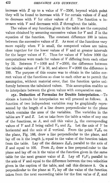
422 ORDNANCE AND GUNNERY.
increase with Z up to a value of V = 2500, beyond which point they will be found to increase with V for certain values of Z and to decrease with V for other values of Z. The function u increases with V and decreases with Z throughout the table.
The values of any function given in the table are the computed values obtained by assuming successive values for V and Z in the equation of the function. The constant difference 100 is taken between the successive values of Z. As most of the functions vary more rapidly when V is small, the computed values are taken close together for the lower values of V and at greater intervals for the larger values of V. Thus for values of V below 1000 the computations were made for values of V differing from each other by 25. Between V =1000 and V =2000, the difference between the tabular values of V is 50, and above V =2000 the difference is 100. The purpose of this course was to obtain in the tables correct values of" the functions so close to each other as to permit the assumption, without material error, that the function v,aries uniformly between the tabulated values. This assumption enables us to interpolate between the given values with comparative ease.
251. Deduction of Formulas for Double Interpolation.-To obtain a formula for interpolation we will proceed as follows. A function of two independent variables may be graphically represented by the length of a line drawn perpendicular to the plane which contains the axes of the variables. The variables in the tables are V and Z, Let us take from the table a value of anyone of the functions, as A, and call this value to, the corresponding values of V and Z being called Vo and Zoo Let the axis of V be horizontal and the axis of Z vertical. From . the point VoZo on the plane, Fig. 166, draw a line perpendicular to the plane, and layoff on it the length to equal to the value of the function taken from the table. Layoff the distance ZoZ2 parallel to the axis of . Z and equal to 100. From Z2 draw a line perpend:cular to the plane and layoff on it the v.alue of the function given in the same
. table for the next greater value of Z. Layoff Vo V 2 parallel to the axis of V and equal to the difference between the two velocities
. given in the caption of the table, and call this distance h. On a perpendicular to the plane at V 2 layoff the value of the function taken from the next succeeding table for the first va!ue of Z, and
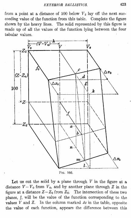
EXTERIOR BALLISTICS. 423
from a point at a distance of 100 below V 2 layoff the next succeeding value of the function from this table. Complete the figure shown by the heavy lines. The solid represented by this figure is made up of all the values of the function lying between the four tabular values.
k· ............. ·• .... ·_·····h, .... ·· .. · .......... ·· .......... ····;.j t;; ...... ·rV' - VoJ-.... · .. ·1r . V; .~ ..... :{.Z .... '.o . . 3 'r' : 0 : : • I
! I' I •
~ i i ~ I ! i I
tZjZo) 1 I : I
100!
I I t 1 ! .. iZ· .. · ---I I
I M't .... M .... Zif'
\ . \ 6vs
. \', : \\,
l·· .. h..: '\ ~ ... -- .. ~ ... - ... --- ... ------.-. .:~--.. ------------------... \
FIG. 166.
Let us cut the solid by a plane through V in the figure at a distance V - V 0 from V 0, and by another plane through Z in the figure at a distance Z - Zo from Zoo The intersection of these two planes, I, will be the value of the function corresponding to the values V and Z. In the column marked Jz in the table, opposite the value of each function, appears the difference between this
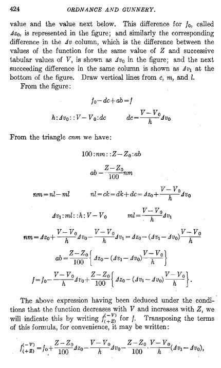
42,4 ORDNANCE AND GUNNERY.
value and the value next below. This difference for 10, called .dz~, is represented in the figure; and similarly the corresponding difference in the .dv column, which is the difference between the values of the function for the same value of Z and successive tabular values of V, is shown as .dvo in the figure; and the next succeeding difference in the same column is shown as .dVl at the bottom of the figure. Draw vertical lines from c, m, and 1.
From the figure:
fo-de+ah=f
h: .d Vo: : V - V 0: de V-Vo
dC=-h-.dvo
From the triangle cnm we have:
nm=n1-m1
lOO:nm : :Z-Zo:ab
Z-Zo ab=lOOnm
V-Vo n1 = ck = dk+ de = .dzo + -h-.dvo
V-Vo m1=-h-.dvl
V-Vo V-Vo . V-Vo nm = .dzo+ -h-.dvo- -h-.dVl = .dzo- (.dVl - .dvo)-h-
z-zor V-Vol ab = 100 t.dzo- (.dVl- .dvo)-h-J
V - Vo Z-Zo r V - Vo} 1=/o--h-.dvo+lOOt.dzo- (.dv1 -.dvo)-h- .
The above expression having been deduced under the condi-· tions that the function decreases with V and increases with Z, we will indicate this by writing f~~;; for f. Transposing the terms of this formula, for convenience, it may be written:
EXTERIOR BALLISTICS. 425
and hy changing the signs according to the manner of the variation of the function with V and Z, we may write the formulas for those functions that vary in a different manner.
The formula give3 the value of the function corresponding to the values of V and Z between the tabular values. If we solve it for V we obtain an expression for the value of V when non-tabular values of the function and of Z are given; and similarly, solving it for Z, the resulting formula will give the value.of Z corresponding to non-tabular values of the function and of V.
The formulas will be of the form given below. 252. Double Int~rpolation Formulas-Ballistic Table II.
/=non-tabular value of any function corresponding to the nontabular values V and Z.
/0 = tabular value of function corresponding to tabular values Vo and Zo, always the nearest values less than V and Z.
h = difference between velocities given in caption of table. Jvo and Jzo = tabular differences for /0, JVl = tabular difference next following Jvo in same table.
f~~;: indicates that function decreases as V increases and iI).creases as Z increases.
Use the following formulas for the functions A, A', B, T', log G', and D' throughout the table. They also apply for some values of the functions A" and log B' when V> 2500.
( V- Vo ) f- fO--h-Jvo
Z=Zo+ v- VoX 100 Jzo- (JVl - JVo)-h-
Use the following formulas for the functions A" and log B' when V <2500, and for some values beyond that point.
426 ORDN ANCE AND GUNNERY.
<+V) Z-Zo V - Vo Z-Zo V - Vo t<+Z) =to+lOOJzO+-h-JvO+lOO ·-h-(Jvt-dvo)
(V - Vo )
1- 10+-h- JvO
Z=Zo+ V- VOX 100 Jzo+ (JVl - JVO)-h-
Use the following formulas for the function u.
(V - Vo )
10+ -h-Jvo - I . Z=Zo+ · V_VoXlOO
Jzo+ (Jvo- JV1)-h-
Inspect the tables to determine how the function varies with V and Z, and select the proper group of formulas.
Exercise great care in the use of the plus and minus signs. Double Interpolation in Simple Tables.-Regarding Fig. 166,
from which the above formulas have been deduced, we will see that the interpolated value I of the function may be obtained from the four tabular values represented by the four heavy corner lines of the figure. Interpolating by the rule of proportional parts between the value 10 of the function and the value immediately below it in the same table for V,which value is represented at Z2 in the figure, we obtain the value of the function at V oZ in the figure. Proceeding in the same manner in the table for the next value of V we obtain the value of the function at V 2Z in the figure.
EXTERIOR BALLISTICS. 4.21
Interpolating between the values at VoZ and V zZ we obtain the desired value f.
This method is the most convenient method of double interpolation in simple tables, such as Table VI of the Ballistic Tables. The numbers in that table are simple and the data is all found together on one page.
USE OF THE FORMULAS.
253. Given Non-Tabular Values of V and Z, to Find f.Select the f formula applicable to the particular function. Take from the table the value of the function corresponding to the tabular values of V and Z next less than the given values. The tabular values of V and Z are Vo and Zo in the formula. Express
V-Vo Z-Zo the fractions -h- and 100 decimally. If we take from the
table at the same time with the function the corresponding numbers in the L1z and L1v columns, also the number next following in the L1v column, called respectively L1zo, L1vo, and L1Vl in the formula, we have all the data necessary for the EOlution of the problem. The numbers in the different columns of the table are obtained by considering the values of the functions as whole numbers. The corrections therefore must be applied to the function as if it were a whole number.
In the examples which follow we will indicate by enclosing the decimal values of functions in parentheses that they are to be considered as whole numbers in applying the corrections.
EXAMPLE.
1. Given V=1015 Z = 37 J,.'B What is the value of A'!
V- Vo= 15 = 3 h 50·
Z-Zo 100 =.42 fo = 0.2946
Jvo=223 JVl =230
f= (0.2946) + .42 X 96-.3 X223-.42 X.3 X7 = (0.2946) +40.32-66.9- .88 = (0.2946) - 27.5 =0.29185
428 ORDNANCE AND GUNNERY.
2. Given V=887 Z=7~75
V- V o=12 = 48 h 25'
What is the value of wg B'f
Z-Zo 100 =.75
f= (0.09779)+ .75XI33+ .48X59- .75X .48Xl =0.099067
To help in fixing the formulas for I in the mind, we will note that the correction for Jz is applied with a positive sign if the function increases with Z, and with a negative sign if the function decreases with Z. The correction for Jv is similarly applied according as the function varies with V. The sign of the last t erm is positive if the signs of the two preceding terms are similar, and negative if they are dissimilar. The difference between the two values of Jv in the last term is usually positive and no attention need be paid to the sign of this difference except when dealing with the functions log B' and log C'.
The formulas used in the above examples, which we will call the f formulas, and which give the values of the functions for nontabular values of V and Z, indicate the simplest and quickest method of arriving at the correct value of an interpolated function. This method should therefore always be followed in solving problems of this nature.
3. Given V =1630 4. Giwm V =972.4 5. Given V = 2790 6. Given V = 2790
Z=3781 Z=9569 Z=1255 Z=8473
Find D' Find A Find log C' Find log C'
Ans. 155.9 Ans. 0.464181 Ans. 4.65946 Ans. 4.97732
Note the difference in the signs of the last term of the formula in the two preceding examples; also the sign of the same term in the following example.
7. Given V=1217 Z=8778 Find log B' Ans.O.138514
Note that in the following example A" decreases with V.
8. Given V =3040 Z =4926 Find A" Ans.2952.4
254. Given Non-Tabular Values of the Function and of V, to Find Z.-Select the Z formula applicable to the particular function. Inspect the table on the page that contains the given value of V to find the proper values to substitute in the formula
EXTERIOR BALLISTICS. 429
for 10, Zo, and the tabular differences. To arrive at accurate results this requires some little care, and is best done in the following manner. By rapid inspection of the table find the two values of the function between which the given value lies. Apply to the tabular value corresponding to the larger value of Z the correc-
V- Vo tion -h-·,dvo. By comparing the corrected tabular value with
the given value we determine on which side of the corrected tabular value the given value lies, and thereby determine which value of Z to use for 10 and the differences in the formula. An example will illustrate this . .
9. Given A =O.061~1 V = ~19~ Find Z.
V~Vo=.92
Looking in the table for V =2100 we find that the given value of A lies between the values corresponding to Z = 5100 and Z = 5200. Applying to the value of the function corresponding to
V- Vo the larger value of Z the correction -h-,dvo = .92 X 571 = 525
we have (0.06263)-525=0.05738 as the value of the function for V =2192 and Z =5200. This value is less than the given value by about 380, and as the function increases with Z the given value lies below it in the table.
The tabular ,dz for the value of the function, 0.06263, that we have taken from the table, is about 190; that is the function is here increasing by about 190 for each tabular value of Z. The tabular function when corrected gave us a value too small by 380. Consequently if we take the second value of Z greater than 5200, the one we have used, we shall probably have the value we seek.
We will therefore take the function for Z =5400 and apply the correction to get its value for V =2192. The corrected value is (0.06639) - .92 X 602 = 0.060852. As this is less than the given value of A and close to it, we know that the given value lies between Z =5400 and Z =5500, and we will use Z =5400 and the corresponding tabular values in the formula.
It will be observed in each of the formulas for Z and V that, in the numerator of the last term, there is a term in parentheses
43J ORDNANCE AND GUNNERY.
containing /0 plus or minus a correction. This term in parentheses is the tabular value of the function corrected for the difference between the given value of V or Z and the next less tabular value. It is essential, in order to arrive at correct results, that the value 0/ this term be /ound first for, as shown above, it is only by this means that we can determine the true tabular values of Z or V between which the required value lies. It will be shown later that without these values correct results cannot be obtained.
In this example we have found the value of the term in parentheses to be (0.06639)- .92 X 602 =0.060852. Using this in the formula with the given value of the function and the tabular quantities corresponding to /0, the process becomes exceedingly simple, and the required value is easily and quickly and accurately obtained.
Zo=5400 /0=0.06639 .Jzo=193 .Jvo=602 .Jvl=618
6121- 6085.2 Z =5400+193_16X.92100
358 Z =5400+ 1782100=5420.1
If we had not pursued the above course, but had used for Zo the smaller value of Z obtained at our first inspection of the table, the result would have been as follows.
6121- 5568.4 Z =5100+ 184-16X .92100 =5432.6
The difference in the results is due to the fact that in using the value Z =5100 we assume that the function varies uniformly between this value and the obtained value, a difference of 332, while our process of interpolation is based on the assumption that the variation is uniform for a difference in Z of 100 only.
The effect of the difference in the values of Z obtained by the twe methods may be seen in the problem from which the above data were taken. The value of the ballistic coefficient, C, was . 4.7859 and the range X was required. X =ZC.
With Z =5420.1 With Z =5432.6
X =25940 ft. X =26000 ft.
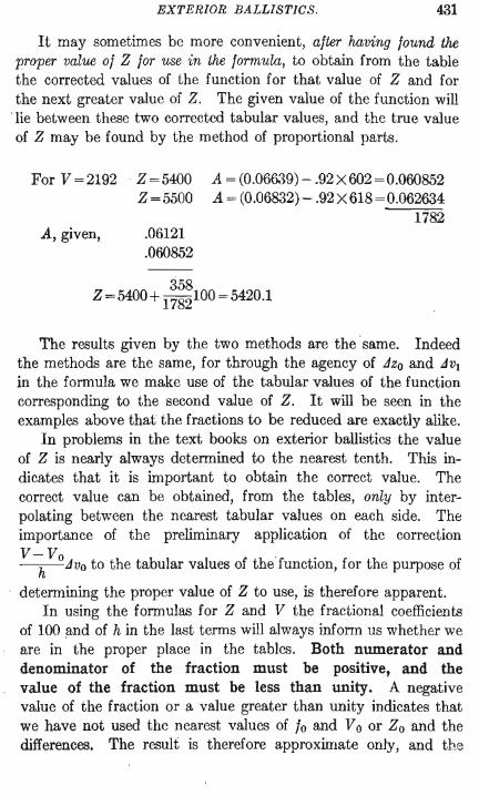
EXTERIOR BALLISTICS. 431
It may sometimes be more convenient, after having found the proper value of Z for use in the formula, to obtain from the table the corrected values of the function for that value of Z and for the next greater value of Z. The given value of the function will
. lie between these two corrected tabular values, and the true value of Z may be found by the method of proportional parts.
For V =2192
A, given,
Z=5400 Z=5500
.06121
.060852
A = (0.06639) - .92 X 602 =0.060852 A = (0.06832)- .92X618=0.062634
1782
358 Z = 5400 + 1782100 = 5420.1
The results given by the two methods are the same. Indeed the methods are the same, for through the agency of Jzo and JVl in the formula we make use of the tabular values of the function corresponding to the second value of Z. It will be seen in the examples above that the fractions to be reduced are exactly alike.
In problems in the text books on exterior ballistics the value of Z is nearly always determined to the nearest tenth. This indicates that it is important to obtain the correct value. The correct value can be obtained, from the tables, only by interpolating between the nearest tabular values on each side. The importance of the preliminary application of the correction V-Yo --h-Jvo to the tabular values of the function, for the purpose of
determining the proper value of Z to use, is therefore apparent. In using the formulas for Z and V the fractional coefficients
of 100 !1nd of h in the last terms will always inform us whether we are in the proper place in the tables. Both numerator and denominator of the fraction must be positive, and the value of the fraction must be less than unity. A negative value of the fraction or a value greater than unity indicates that we have not used the nearest values of fo and Vo or Zo and the differences. The result is therefore approximate only, and th.e

432 ORDNANCE AND GUNNERY.
degree of approximation varies with the num1;>er of units in the value of the fraction.
The formulas for V and Z may be easily fixed in the memory if we observe that the numerator of the last term is the difference between the given value of the function and the nearest corrected tabular value, the correction being applied to the tabular value with a sign indicated by the manner of variation of the function with Z or V. The first term of the denominator is Jvo in the V formulas, and Jzo in the Z formulas. The sign of the second term of the denominator is the same as the sign inside the parentheses of the numerator. The value of the second term of the denominator is positive for all the functions except log B' and log G'. For some value of log B', and for most values of log G', JVl is less than Jvo, so that (JVl- Jvo) becomes negative and causes a change of sign for the second term of the denominator in the V and Z formulas, and for the last term in the f formulas.
10. Given u=991 V =1630 Find Z.
V-Vo=30= 6 h 50·
This value of u apparently lies between the values of Z = 4600
b I · h . V-Yo and Z = 4700, ut app ymg t e correctIOn -h- Jvo = .6 X 15 = 9
to 987, the tabular value of the function for Z =4700, adding it since u increases with V, we find that the value of u for V=1630 and Z =4700 is 996. This being greater than our given value, and the function decreasing with Z, the given value corresponds to a value of Z greater than 4700. Similar inspection shows that the proper value of Z is less than 4800. We therefore use the values for Z =4700 in the formula.
Zo=4700 10=987 Jzo=6 Jvo=15 JVl=15
Z =4700+ 99:~~91100 =4783.3
11. Given A" =2158 V=979 Find Z.
V~Vo=.16
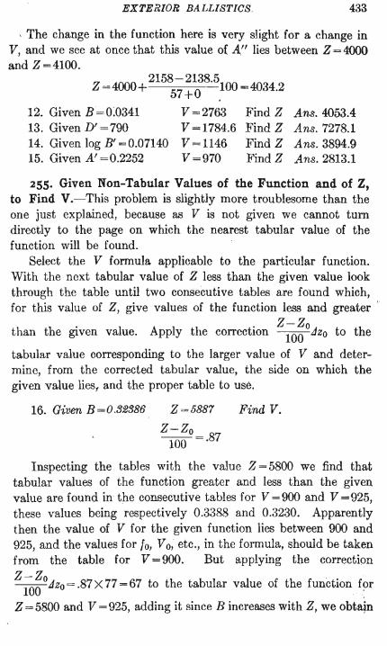
EXTERIOR BALLISTICS. 433
, The change in the function here is very slight for a change in V, and we see at once that this value of AI' lies between Z = 4000 and Z=4100.
Z =4000+ 21585~!~8.5.100=4034.2
12. Given B=0:0341 V =2763 Find Z Ans.4053.4 13. Given D' = 790 V = 1784.6 Find Z Ans. 7278.1 14. GivenlogB'=0.07140 V=1146 FindZ Ans.3894.9 15. Given A' =0.2252 V =970 Find Z Ans.2813.1
255. Given Non-Tabular Values of the Function and of Z, to Find V.-This problem is slightly more troublesome than the one just explained, because as V is not given we cannot turn directly to the page on which the nearest tabular value of the function will be found.
Select the V formula applicable to the particular function. With the next tabular value of Z less than the given value look through the table until two consecutive tables are found which, for this value of Z, give values of the function less and greater '
Z-Zo than the given value. Apply the correction lOOdzo to the
tabular value corresponding to the larger value of V and determine, from the corrected tabular value, the side on which the given value liesr and the proper table to use.
16. Given B=O.32386 Z =5887 Find V.
Z-Zo 100 =.87
Inspecting the tables with the value Z = 5800 we find that tabular values of the function greater and less than the given value are found in the consecutive tables for V =900 and V =925, these values being respectively 0.3388 and 0.3230. Apparently then the value of V for the given function lies between 900 and 925, and the values for to, Yo, etc., in the formula, should be taken from the table for V =900. But applying the correction Z-Zo lOOdzo=.87X77=67 to the tabular value of the function for
Z = 5800 and V = 925, adding it since B increases with Z, we obtajn
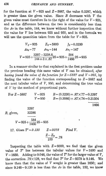
434 ORDNANCE AND GUNNERY.
for the function at V =925 and Z =5887, the value 0.3297, which is greater than the given value. Since B decreases with V the given value must therefore lie to the right of the value for V =925, and as the difference between the two is considerably less than the .Iv in the table, 144, we know without further inspection that the value for V lies between 925 and 950, and in the formula we will use the quantities taken from the table for V =925.
Vo=925 Zo=5800 fo=0.3230
Jzo=77 Jvo= 144 JVl = 147
3297 - 3238.6 584 V = 925 + 144+ 3 X .87 25 = 925+ 1466 25 = 935
In a manner similar to that explained in the first problem under the previous heading this same value of V can be obtained, after having found the value of the function for Z =5887 and V =9~5, by finding the value of the function corresponding to Z = 5887 and the next tabular value of V, 950, and determining the true value of V by the. method of proportional parts.
For Z=5887
3297
V=925 V=950
B, . given, 32386
B= (0.3230)+ .87X77 =0.3297 B= (0.3086)+ .87X74=0.31504
1466
584 V =925+ 1466 25=935
17. Given T'=9.130 Z=9378
Z-Zo 100 =.78
Find V.
Inspecting the table with Z =9300, we find that the given value of T' lies between the tabular values for V = 1600 and . V = 1650. Adding to 9.046, the value of T' for the larger value of V, the correction .78X128, we find that T' for Z=9378 is 9.146. We know then that the value of V sought is greater than 1650; and since 9.146-9.130 is less than the .Iv in the table, 152, we know
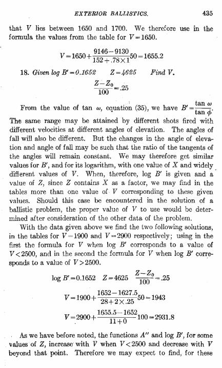
EXTERIOR BALLISTICS. 435
that V lies between 1650 and 1700. We therefore use in the fommla the values from the table for V = 1650.
9146-9130 V = 1650+ 152 + .78X 150 = 1655.2
18. Given log B' =0.16512 Z =46125 Find V.
Z-Zo 100 =.25
. ' tan cu From the value of tan cu, equatIOn (35), we have B' = tan <p'
The same range may be attained by different shots fired with different velocities at different angles of elevation. The angles of fall will also be different. But the changes in the angle of elevation and angle of fall may be such that the ratio of the tangents of the angles will remain constant. We may therefore get similar values for B', and for its logarithm, with one value of X and widely different values of V. When, therefore, log B' is given and a ' value of Z, since Z contains X as a factor, we may find iIi the tables more than one value of V corresponding to these given values. Should this case be encountered in the solution of a ballistic problem, the proper value of V to use would be determined after consideration of the other data of the problem.
With the data given above we find the two following solutions, in the tables for V = 1900 and V = 2900 respectively; using in the first the formula for V when log B' corresponds to a value of V <2500, and in the second the formula for V when log B' cor~esponds to a value of V> 2500.
Z-Zo log B'=0.1652 Z =4625 100 =.25
V =1900 1652-1627.550 =1943 + 28+2X.25
V ~2900+ 1655i~~~652100=2931.8
Ai; we have before noted, the functions A" and log B', for some values of Z, increase with V when V < 2500 and decrease with V beyond that point. Therefore we may expect to find, for these
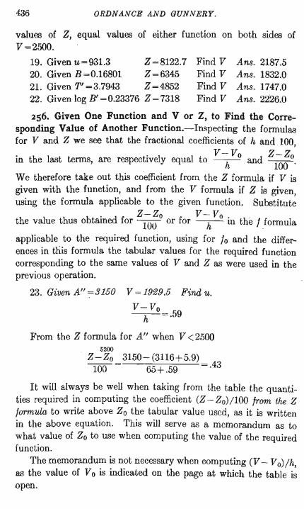
436 ORDNANCE AND GUNNERY.
values of Z, equal values of either function on both sides of V =2500.
19. Given u=931.3 Z=8122.7 Find V Ans. 2187.5 20. Given B=0.16801 Z=6345 Find V Ans. 1832.0 21. Given T' =3.7943 Z=4852 Find V Ans. 1747.0 22. Given log B' =0.23376 Z =7318 Find V Ans.2226.0
256. Given One Function and V or Z, to Find the Corresponding Value of Another Function.-Inspecting the formulas for V and Z we see that the fractional coefficients of hand 100,
V- Vo Z-Zo in the last terms, are respectively equal to -h- and ToO' We therefore take out this coefficient from the Z formula if V is given with the function, and from the V formula if Z is given, using the formula applicable to the given function. Substitute
Z-Zo V- Vo the value thus obtained for 100 or for -h- in the I formula
applicable to the required function, using for 10 and the differences in this formula the tabular values for the required function corresponding to the same values of V and Z as were used in the previous operation.
23. Given A" =3150 V = 19~9 ,5 Find u.
V-Vo -h-=·59
From the Z formula for A" when V <2500 5200
Z-Zo 3150- (3116+5.9) 100 65+ .59 =.43
It will always be well when taking from the table the quantities required in computing the coefficient (Z - Zo) 1100 from the Z formula to write above Zo the tabular value used, as it is written in the above equation. This will serve as a memorandum as to what value of Zo to use when computing the value of the required function.
The memorandum is not necessary when computing (V - Vo) Ih, as the value of Vo is indicated on the page at which the table is .open.