positioning analysis of multiple antennas in a dense rfid reader environment kin seong leong auto-id...
TRANSCRIPT

AUTO-ID LABSPositioning Analysis of
MultipleAntennas in a Dense RFID
ReaderEnvironment
Kin Seong Leong
Auto-ID Lab, ADELAIDE

AUTO-ID LABS Objectives
Investigate the art of antenna positioning.
Minimise RFID collision problem by proper antenna positioning.
Set up a convenient simulation environment in MATLAB.
Provide a foundation for more advanced analysis.

AUTO-ID LABS Main Challenges in Simulation
Simulation model
Underlying assumptions

AUTO-ID LABS Simulation Model (The concept of free space
path loss)

AUTO-ID LABS Simulation Model: 1
0
20
40
60
80
100
120
140
1 10 100
Transmitter-Receiver Seperation/ m
Pat
h L
oss/
dB n=4
n=3
n=2
n=1
n=6
n=5
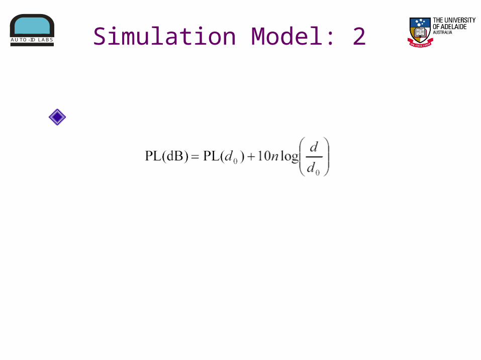
AUTO-ID LABS Simulation Model: 2
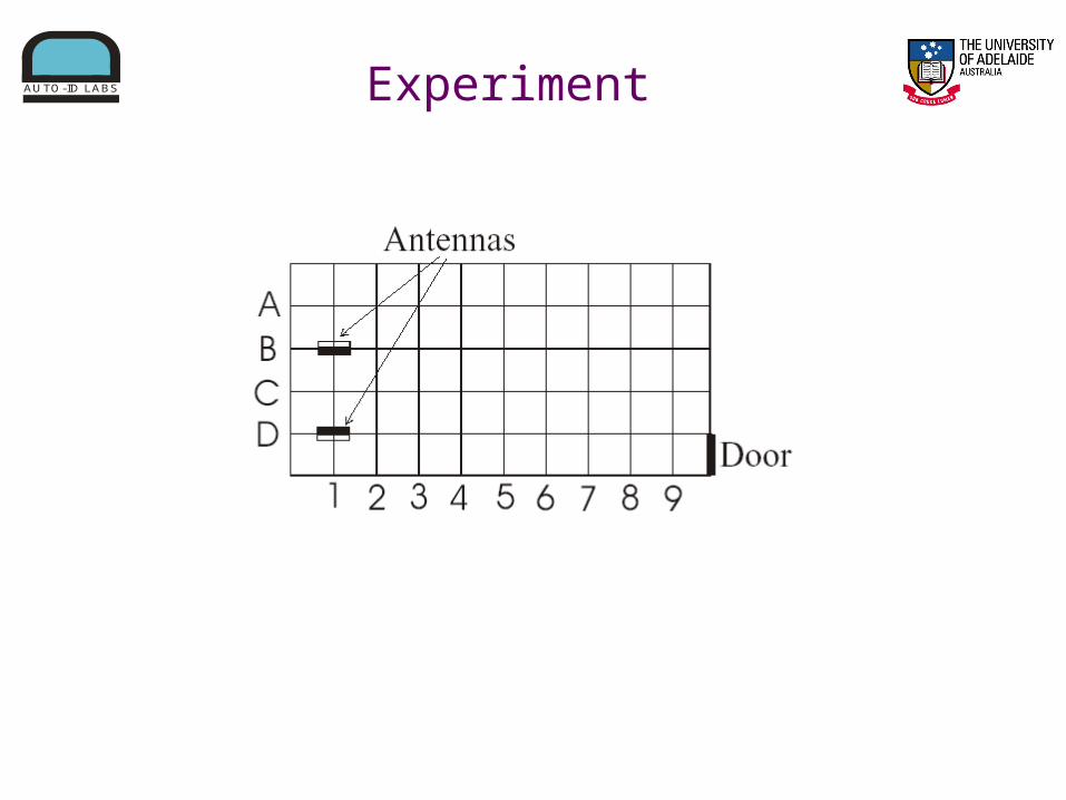
AUTO-ID LABS Experiment

AUTO-ID LABS Simulation Model
n also changes as the distance increases. Hence:
The boundary of d = 8 is based on the experiment results, also consistent with Rappaport’s results. However, it is an average and may change in some extreme environments.

AUTO-ID LABS Simulation Assumptions
Negligible reflection, empirically justified.
All Antennas deployed
have similar gain
pattern,orientations may vary

AUTO-ID LABS Simulation Concept
The simulator accepts input data:a) Location of antennab) Transmit power into the antenna c) Antenna gain pattern
Output of the simulator:a) Signal strength at various locations when measured with a 0dBi gain antenna.

AUTO-ID LABS Simulation Concept
Example output:One antenna located at (50,50) and both axes in unit of m.

AUTO-ID LABS Regulations
“Listen Before Talk” – ETSI 302 208
The threshold values:

AUTO-ID LABS Results Interpretation
Antenna radiating 2.0 W ERP at (50,50). The next antenna to be placed at the side must be 150 m away if the next antenna would want to radiate in the same channel.
350 m
150 m

AUTO-ID LABS Results Interpretation
Antennas radiating 2.0 W ERP at (50,50) and (400,50).

AUTO-ID LABS Simulation Variation

AUTO-ID LABS Results Interpretation
Antenna radiating 2.0 W ERP at (50,50).Antenna on ground radiating 2.0 W ERP at (400,50).
Reduced
Reduced
AUTO-ID LABS Frequency Channelling
So far, all the simulations are dealing with same channel radiation.

AUTO-ID LABS Frequency Channelling
Transmit Mask for Dense-Interrogator Environments:(extracted from EPCglobal C1G2)

AUTO-ID LABS Frequency ChannellingBoth antennas operating 3 channels away from channel of interest.The black line indicates the boundary where a antenna can be positioned to operate in the channel of interest.

AUTO-ID LABS Summary of Results
Note that these results are only true when an isotropic 0dBi receiver antenna is used. When a directional antenna is used as the receiver, the results will be very different depending on the angle between the transmitting and receiving antenna.

AUTO-ID LABS Summary of Results
The results shown is very challenging for RFID deployment.
Luckily, various policies can be adopted to improve the situation. These include:a) Synchronizationb) RF shielding c) Optimising reading timed) Optimising radiated powere) Sensor controlled readers

AUTO-ID LABS Future Work
A systematic way of determining n Changes with different environments
A more user friendly simulator.

AUTO-ID LABS
Thank you
Questions?