probing systems seminar
TRANSCRIPT
Probing Systems
S Austin Moses
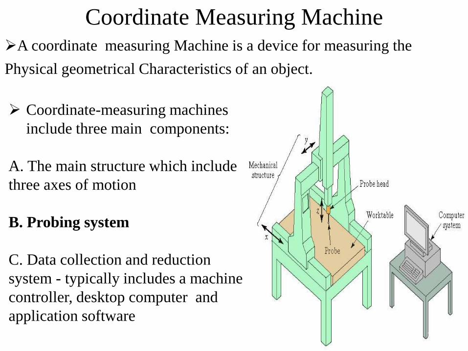
Coordinate Measuring MachineA coordinate measuring Machine is a device for measuring the
Physical geometrical Characteristics of an object.
Coordinate-measuring machines
include three main components:
A. The main structure which include
three axes of motion
B. Probing system
C. Data collection and reduction
system - typically includes a machine
controller, desktop computer and
application software2
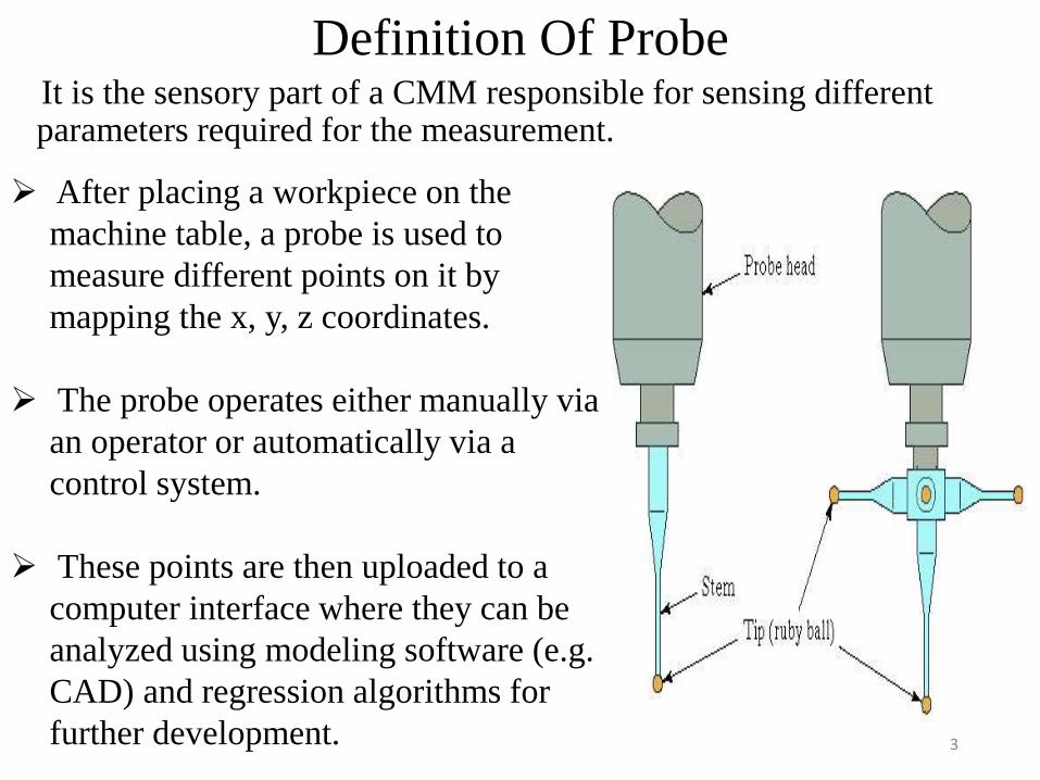
Definition Of ProbeIt is the sensory part of a CMM responsible for sensing different
parameters required for the measurement. laser scanning probes or non-contact probes.
After placing a workpiece on the
machine table, a probe is used to
measure different points on it by
mapping the x, y, z coordinates.
The probe operates either manually via
an operator or automatically via a
control system.
These points are then uploaded to a
computer interface where they can be
analyzed using modeling software (e.g.
CAD) and regression algorithms for
further development. 3
CMM Operation and Controls – Four Main Categories
Manual drive CMM – human operator physically moves the probe and records x-y-z- data
Manual drive and computer-assisted data processing – can perform calculations to assess part features
Motor-driven CMM with computer-assisted data processing – uses joystick to actuate electric motors to drive probe
Direct computer control (DCC) – operates like a CNC machine tool and requires part program
4
SensorsThe devices used to explore the area to acquire coordinates are the
"sensors".
Two types of sensors:
“Tactile” sensors.
“Noncontact” sensors or "optoelectronic" sensors
Tactile sensors distinguish:
“Rigid” sensors.
“Point to point” sensors.
“Continuous” sensors
In non contact sensors ,Two main principles are used:
Triangulation 3D
Time of Flight 5

SensorsPoint to Point Tactile Sensors
The point to point type of measurement determines the position of points by bringing in physical contact the tip of the sensors with the part and then retracting.
The point to point measurement represents a fast ideal solution to define Dimension and Position.
Probing (point measurement) sequences
Legend:
1......: Starting point.
2......: Point probing.
3......: Disengagement
after point probing
6
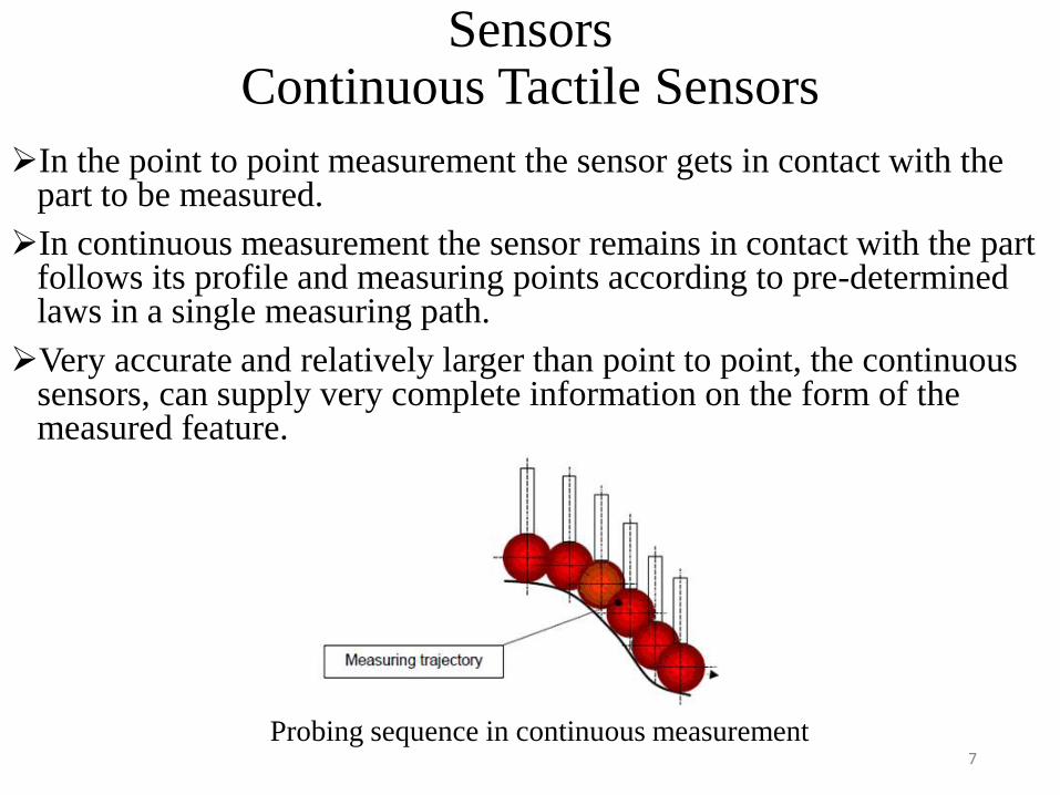
SensorsContinuous Tactile Sensors
In the point to point measurement the sensor gets in contact with the part to be measured.
In continuous measurement the sensor remains in contact with the part follows its profile and measuring points according to pre-determined laws in a single measuring path.
Very accurate and relatively larger than point to point, the continuous sensors, can supply very complete information on the form of the measured feature.
Probing sequence in continuous measurement 7

Deviations from a Nominal Surface
Surface measurement can be displayed as the profile of the surface as indicated by the stylus trace or the average of the surface deviations during the trace
8
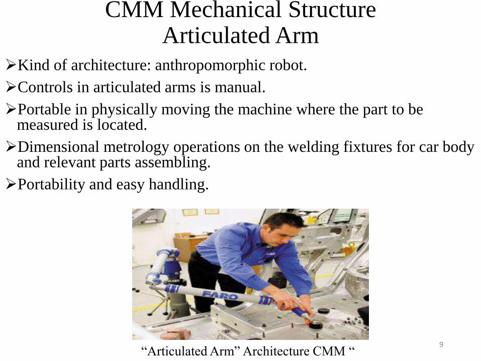
CMM Mechanical StructureArticulated Arm
Kind of architecture: anthropomorphic robot.
Controls in articulated arms is manual.
Portable in physically moving the machine where the part to be measured is located.
Dimensional metrology operations on the welding fixtures for car body and relevant parts assembling.
Portability and easy handling.
“Articulated Arm” Architecture CMM “9
Articulation Or Fixed Sensors?Articulating heads are a standard feature on the majority of
computer-controlled CMMs
Heads are the most cost-effective way to measure complex parts
Flexibility - a single, simple stylus can access features in many
orientations
Indexing and continuously variable solutions
Speed - indexing is faster than stylus changing (done during CMM
moves)
Dynamic response - simple, light styli make for a lower suspended
mass
Costs
simple styli with low replacement costs
small, low cost stylus change racks10

Articulating Heads - Disadvantages
Space - a head reduces available Z travel by a small amount - can be an issue on very small CMMs
Slide 11
PH10MQ in-quill
version of PH10
indexing head
reduces Z travel
requirements
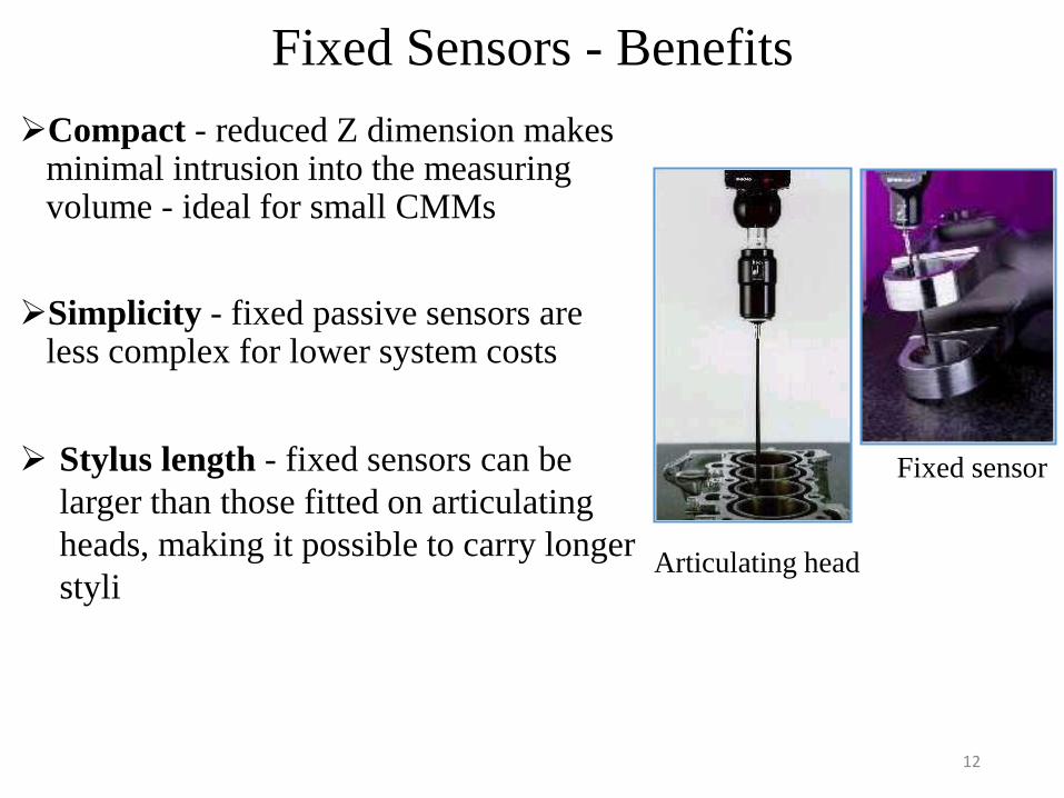
Fixed Sensors - Benefits
Compact - reduced Z dimension makes minimal intrusion into the measuring volume - ideal for small CMMs
Simplicity - fixed passive sensors are less complex for lower system costs
Stylus length - fixed sensors can be
larger than those fitted on articulating
heads, making it possible to carry longer
styli Articulating head
Fixed sensor
12

Fixed Sensors - Disadvantages
Programming complexity - complex stylus clusters mean more attention must be paid to collision avoidance
DANGER!
Possible collisions with:
Component fixturing
Stylus change rack
Other styli in rack
Machine structure
13
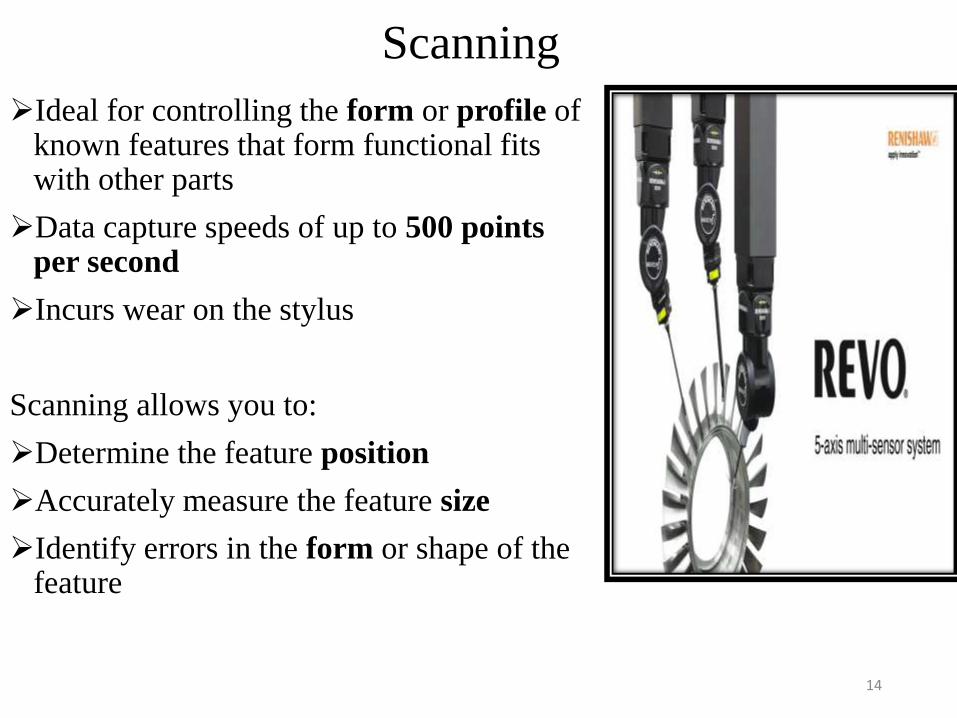
Scanning
Ideal for controlling the form or profile of known features that form functional fits with other parts
Data capture speeds of up to 500 points per second
Incurs wear on the stylus
Scanning allows you to:
Determine the feature position
Accurately measure the feature size
Identify errors in the form or shape of the feature
14
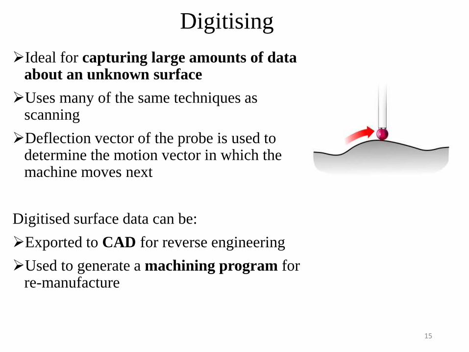
Digitising
Ideal for capturing large amounts of data about an unknown surface
Uses many of the same techniques as scanning
Deflection vector of the probe is used to determine the motion vector in which the machine moves next
Digitised surface data can be:
Exported to CAD for reverse engineering
Used to generate a machining program for re-manufacture
15
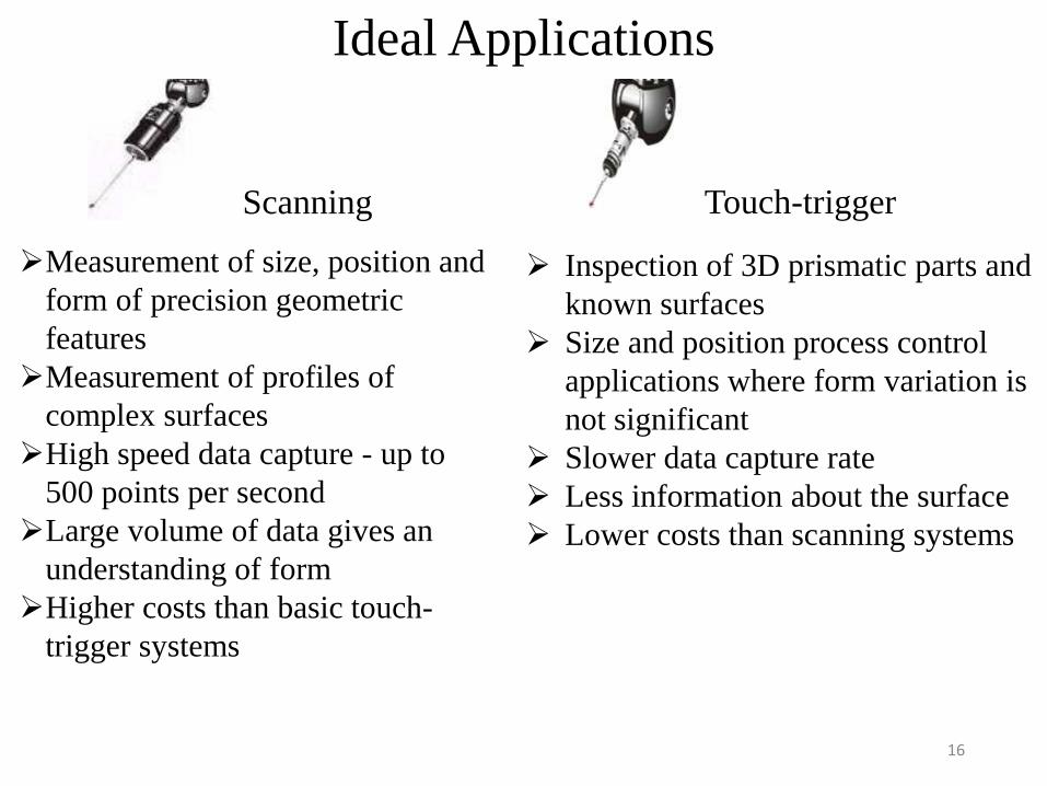
Ideal Applications
Measurement of size, position and
form of precision geometric
features
Measurement of profiles of
complex surfaces
High speed data capture - up to
500 points per second
Large volume of data gives an
understanding of form
Higher costs than basic touch-
trigger systems
Inspection of 3D prismatic parts and
known surfaces
Size and position process control
applications where form variation is
not significant
Slower data capture rate
Less information about the surface
Lower costs than scanning systems
Scanning Touch-trigger
16
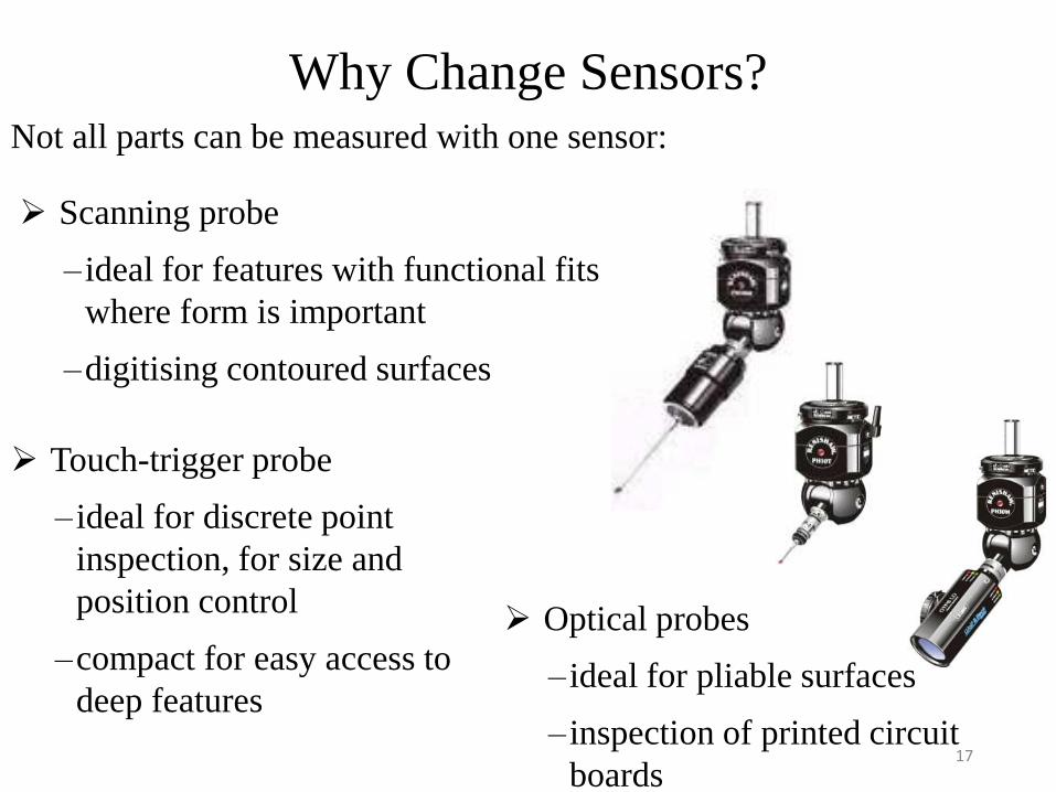
Why Change Sensors?Not all parts can be measured with one sensor:
Scanning probe
– ideal for features with functional fits
where form is important
–digitising contoured surfaces
Optical probes
– ideal for pliable surfaces
– inspection of printed circuit
boards
Touch-trigger probe
– ideal for discrete point
inspection, for size and
position control
–compact for easy access to
deep features
17
Advantages Of Using CMMs Over Manual Inspection
Reduced inspection cycle time – translates to higher throughput rate
Especially with DCC, approximately 90% reduction in certain tasks
Flexibility – CMMs are general-purpose machines
Reduced operator errors in measurement and setup
Greater inherent accuracy and precision
Avoidance of multiple setups – in general all measurements of a given part can be made in one setup
18
Inspection Probes On Machine Tools
Mounted on toolholders
Stored in the tool drum
Handled by the automatic tool-changer the same way cutting tools are handled
Inserted into the machine tool spindle by the automatic tool-changer
When mounted in the spindle the machine tool is controlled very much like a CMM
Sensors in the probe determine when contact is made with part surface so that required data processing is performed to interpret the sensor signal
19
References
• Renishaw PLC, Metrology Division, New Mills, Wotton-under-Edge, Gloucestershire, UK, Technical Literature, available at <http://www. renishaw.co.in/en/> (accessed on May 15th, 2014).
• Mikell P. Groover, Inspection technologies. In: Automation, Production Systems, and Computer-Integrated Manufacturing,Third Edition, Lehigh University, Pennsylvania, USA.