product catalogue · applications with high inrush currents, i.e., transformers, and motors....
TRANSCRIPT

A C L C A B L E S / P R O D U C T G U I D E 01
PRODUCT CATALOGUE
MCB | RCD | ISOLATOR

02 A C L C A B L E S / P R O D U C T G U I D E
A C L C A B L E S / P R O D U C T G U I D E 03
MCBTECHNICAL DESCRIPTIONFor use in commercial and industrial electrical distribution systems.Protects against overloads and short circuits, switching and isolation.
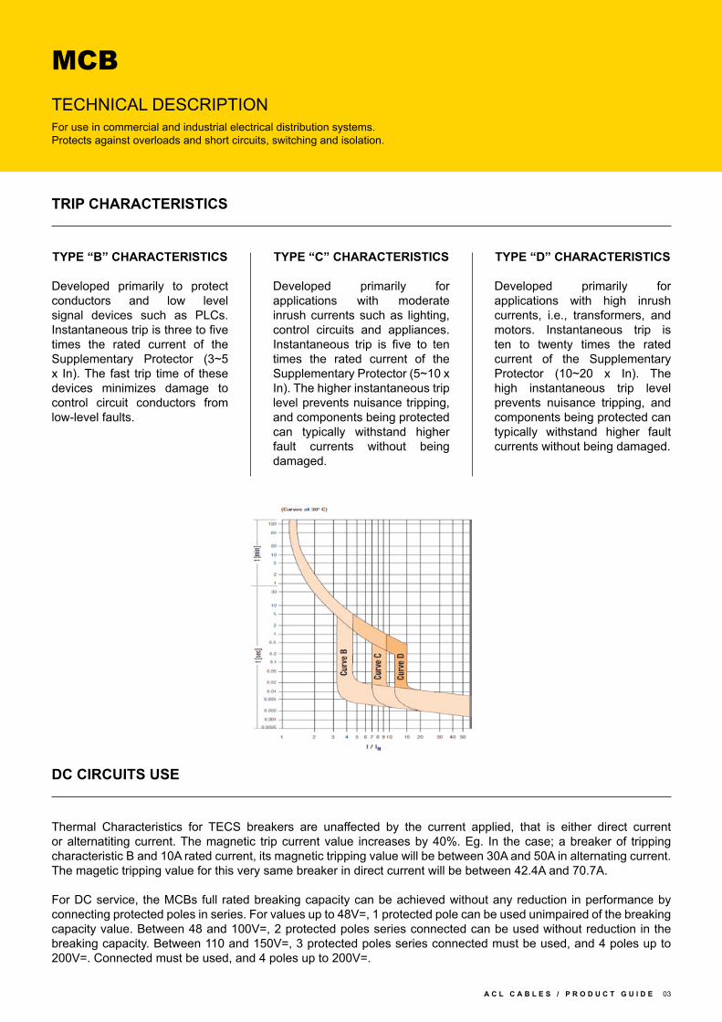
TYPE “B” CHARACTERISTICS
Developed primarily to protect conductors and low level signal devices such as PLCs. Instantaneous trip is three to five times the rated current of the Supplementary Protector (3~5 x In). The fast trip time of these devices minimizes damage to control circuit conductors from low-level faults.
Thermal Characteristics for TECS breakers are unaffected by the current applied, that is either direct current or alternatiting current. The magnetic trip current value increases by 40%. Eg. In the case; a breaker of tripping characteristic B and 10A rated current, its magnetic tripping value will be between 30A and 50A in alternating current. The magetic tripping value for this very same breaker in direct current will be between 42.4A and 70.7A.
For DC service, the MCBs full rated breaking capacity can be achieved without any reduction in performance by connecting protected poles in series. For values up to 48V=, 1 protected pole can be used unimpaired of the breaking capacity value. Between 48 and 100V=, 2 protected poles series connected can be used without reduction in the breaking capacity. Between 110 and 150V=, 3 protected poles series connected must be used, and 4 poles up to 200V=. Connected must be used, and 4 poles up to 200V=.
TRIP CHARACTERISTICS
DC CIRCUITS USE
TYPE “C” CHARACTERISTICS
Developed primarily for applications with moderate inrush currents such as lighting, control circuits and appliances. Instantaneous trip is five to ten times the rated current of the Supplementary Protector (5~10 x In). The higher instantaneous trip level prevents nuisance tripping, and components being protected can typically withstand higher fault currents without being damaged.
TYPE “D” CHARACTERISTICS
Developed primarily for applications with high inrush currents, i.e., transformers, and motors. Instantaneous trip is ten to twenty times the rated current of the Supplementary Protector (10~20 x In). The high instantaneous trip level prevents nuisance tripping, and components being protected can typically withstand higher fault currents without being damaged.

04 A C L C A B L E S / P R O D U C T G U I D E
Product Code/Model VSM6K/1P-C6, VSM6K/1P-C10, VSM6K/1P-C16, VSM6K/1P-C20, VSM6K/1P-C32
Rated Capacity Phase to Neutral 230V/240V~ / Phase to Phase 400V/415V~
Rigid Conductor 25mm² Maximum
Flexible Conductor 16mm² Maximum
Characteristics C CURVE / D CURVE
Capacity 6 kA / 10kA
Standards EN 60898 / EN 60947-2 / KEMA / SEMCO / SNI / CE / ROHS
Frequency 50/60Hz
Calibration Temperature 30˚C
Electrical Endurance 8000
Mechanical Endurance 20000
MCBSPECIFICATION

A C L C A B L E S / P R O D U C T G U I D E 05
010mA Suitable for use in special applications where additional protection against contact is essential
030mA Tripping current to provide additional protection against direct contact shock
100mA Suitable for use against direct contact shock or where protection is guard against fire hazards etc.
300mA Suitable for use in large installations where equipment protection are main considerations and high levels
of earth leakage are experienced.
RCDSHORT CIRCUIT PROTECTION DEVICE (SCPD)
TECHNICAL DESCRIPTIONProviding protection against overload and short-circuit currents and protects people againstearth fault currents: direct or indirect contact, fire…………….
The RCD employs the current balance principle which involves the supply conductors to the load (phase and neutral) wound onto a common transformer core to form the primary windings. Under healthy conditions, the current in the phase conductor is equal to the current in the neutral and the vector sum of the current is zero.
In the event of an earth fault, an amount of current will flow to earth, creating an out of balance situation in the transformer assembly. This out of balance detected by the secondary winding of the transformer will activate the trip mechanism at a pre-determined level. Single phase and neutral or three phases and neutral units (suitable for both 3 wire and 4 wire systems) are available, the latter being suitable for balanced or unbalanced 3 phase loads. The RCD tripping mechanism will operate at a residual current of between 50%-100% of its rated tripping current. (Sensitivity)
Semi-conductor devices are extensively integrated in equipments in industries, commerce and in our homes. They can be found in control panels to computers to toys.
As equipments are fed from the mains electrical supply; in the event of an earth fault, the presence of semi-conductors may result in the normal AC waveform being replaced by a non-sinusoidal fault current. In some cases, the waveform may be rectified. These waveforms are said to contain a pulsating DC component which can either partially desensitize a standard type AC RCD.
International standards IEC 1008 (RCCBs) and IEC 1009 (RCBOs) divide RCDs into two performance classes:
Type AC RCDs for which tripping is ensured for residual sinusoidal alternating currents; whether suddenly applied or slowly arising.
Type A RCDs for which tripping is ensured for residual sinusoidal alternating currents and residual pulsating direct currents, whether suddenly applied or slowly arising.
TRIP CHARACTERISTICS
FAULT CURRENT SENSITIVITY
RESIDUAL TRIPPING CURRENTS

06 A C L C A B L E S / P R O D U C T G U I D E
Product Code/Model VSR/2P/40-30
Rated Capacity 40A
Rigid/Flexible Conductor 35mm²/25mm² MAXIMUM
Calibration Temperature 30˚C
Frequency 50/60Hz
Electrical Endurance 10000
Mechanical Endurance 20000
Standards EN 61008-1/EN 61008-2-1/ROHS/CE
Poles 2P; Ue: 230 Vac, 50/60 Hz
IΔn 30 mA
Inc = IΔc 6 kA; Im = IΔm: 10 In or 500 A whichever is the greater;
Operating Time min. 0.3s
Residual Operating Current 0.5IΔn ~ 1IΔn
IP Rating IP20
SCPD 40A MCB, 6KA
RCDSPECIFICATION

A C L C A B L E S / P R O D U C T G U I D E 07
ISOLATORSPECIFICATION
Product Code/Model VSI/2P/40
Rated Current 40A
Poles 2P
Rated Voltage 230V/240V~ / 400V/415V~
Capacity 6kA
Rated Short Time Withstand Current ICW = 20 In 1s
Rated Short Current Capacity ICM = 15 In
Frequency 50/60Hz
Standards EN 60947-3 / CE / ROHS
Rigid Conductor 25mm² Maximum
Flexible Conductor 16mm² Maximum
Mounting MCB DIN Rail
Optimal protection against unintentional touch of live parts.*For domestic installation

08 A C L C A B L E S / P R O D U C T G U I D E
ACL Cables PLC, 60, Rodney Street, Colombo 08, Sri Lanka
T : +94 11 760 8300 F : +94 112 699 503 W : www.acl.lk +94 11 269 7652 E : [email protected]