radar imaging for combatting terrorism - researchgate
TRANSCRIPT

RADAR IMAGING FOR COMBATTING TERRORISM
Hugh D. Griffiths† and Chris J. BakerDepartment of Electronic and Electrical EngineeringUniversity College London, London, UK
Abstract. Radar, and in particular imaging radar, have many and varied applications to coun-terterrorism. Radar is a day/night all-weather sensor, and imaging radars carried by aircraft orsatellites are routinely able to achieve high-resolution images of target scenes, and to detect andclassify stationary and moving targets at operational ranges. Short-range radar techniques may beused to identify small targets, even buried in the ground or hidden behind building walls. Differentfrequency bands may be used, for example high frequencies (X-band) may be used to support highbandwidths to give high range resolution, while low frequencies (HF or VHF) are used for foliagepenetration to detect targets hidden in forests, or for ground penetration to detect buried targets.
The purpose of this contribution is to review the fundamental principles of radar imaging, andto consider the contributions that radar imaging can make in four specific aspects of counterter-rorism: through-wall radar imaging, radar detection of buried targets, tomography and detection ofconcealed weapons, and passive bistatic radar.
Key words: radar imaging, ground penetrating radar, passive bistatic radar
1. Introduction
Radar techniques and technology have been developed over many decades. Radarhas the key attributes of day/night, all-weather performance, and also the abilityto measure target range accurately and precisely. The techniques of imaging radardate back to the Second World War, when crude radar images were obtained onthe displays of airborne radar systems, allowing features such as coastlines tobe distinguished. A major advance took place in the 1950s, when Wiley in theUSA made the first experiments with airborne synthetic aperture radar (Wiley,1985), and nowadays synthetic aperture radar is an important part of the radarart, with radar imagery from satellites and from aircraft routinely used for geo-physical remote sensing and for military surveillance purposes. The enormousadvances that have been made in imaging radar since the 1950s owe a great dealto the development of fast, high-performance digital processing hardware andalgorithms.
† Shortly to take up an appointment as Principal of the Defence College of Management andTechnology, Shrivenham, Cranfield University, UK.
c© 2006Springer. Printed in the Netherlands.

2 H. D. GRIFFITHS AND C. J. BAKER
The objective of this chapter is to review the application of imaging radarsystems to counterterrorism. In so doing, we need to bear in mind the things thatradar is good at doing, and the things that it is not good at doing. At a fundamentallevel, then, we will be concerned with the electromagnetic properties of the targetsof interest, and of their contrast with the surroundings. We will be concerned withhow these properties vary with frequency, since targets may exhibit resonances(and hence enhanced signatures) at certain frequencies, and with the propagationcharacteristics through materials such as building walls and soil. Hence, we willbe interested in techniques which allow us to distinguish targets from the back-ground, by exploiting differences in signature, and wherever possible making useof prior knowledge. It is likely that additional information may be obtained frommultiple perspective views of targets (Baker et al., 2006). Further informationmay be obtainable through the use of techniques such as radar polarimetry andinterferometry.
There are two distinct stages to this: (i) the production of high-quality, artefact-free imagery, and (ii) the extraction of information from imagery. It should notbe expected that radar images should look like photographs. Firstly radar fre-quencies are very different from those in the optical region. Secondly, radar is acoherent imaging device (just like a laser) and therefore exhibits multiplicativespeckle noise (just like a laser). This makes for an extremely challenging imageinterpretation environment.
The structure of the chapter is therefore as follows. Firstly, we provide a briefreview of the fundamentals of radar imaging, establishing some of the fundamen-tal relations for the resolution of an imaging radar system. This is followed bya discussion of four specific applications to counterterrorism: (i) the detectionof buried targets; (ii) through-wall radar imaging; (iii) radar tomography and thedetection of concealed weapons; (iv) passive mm-wave imaging; and (v) passivebistatic radar. This is followed by some discussion and some comments on futureprospects.
2. Fundamentals of radar imaging
Firstly we can establish some of the fundamental relations for the resolution of animaging radar system. In the down-range dimension, resolution∆r is related tothe signal bandwidthB, thus
∆r =c
2B(1)
wherec is the velocity of propagation. High range resolution may be obtainedeither with a short-duration pulse or by a coded wide-bandwidth signal, such asa linear FM chirp or a step-frequency sequence, with the appropriate pulse com-pression processing. A short-duration pulse requires a high peak transmit powerand instantaneously-broadband operation; these requirements can be relaxed in

RADAR IMAGING FOR COMBATTING TERRORISM 3
the case of pulse compression. With the advances in digital processing power itis now relatively straightforward to generate wideband coded waveforms and toperform the pulse compression processing in the receiver in real time.
In the first instance cross-range resolution is determined by the product of theranger and the beamwidthθB (in radians). The beamwidth is determined by thedimensiond of the antenna aperture and thus the cross-range resolution is givenby
∆x = rθB ≈rλd
(2)
whereλ is the wavelength. As the dimensions of most antennas are limited bypractical considerations (such as fitting to an aircraft) the cross range resolutionis invariably much poorer than that in the down range dimension. However, thereare a number of techniques that can improve upon this. All of these are ultimatelya function of the change in viewing or aspect angle.
The cross range resolution achieved in synthetic aperture radars is determinedby the relative motion between the radar and the object. Consider the scenario inFigure 1.
Figure 1. A target moving perpendicularly past a monochromatic CW radar.
For this geometry, Brown (1967) defines the point target response of a mono-chromatic CW radar as
W(x) = A
(xr
)exp
(j4πλ
√r2 + x2
). (3)
Computation of the instantaneous frequency of the response allows the bandwidthto be written as
B =4πλ
x√
r2 + x2=
4πλ
sin
(∆θ
2
)(4)
and hence the cross range resolution is given by
∆x =π
B=
λ
4 sin(∆θ/2). (5)

4 H. D. GRIFFITHS AND C. J. BAKER
For a linear, stripmap-mode synthetic aperture, equation (5) reduces to∆x = d/2,which is independent of both range and frequency. Even higher resolution can beobtained with a spotlight-mode synthetic aperture, steering the real-aperture beam(either mechanically or electronically) to keep the target scene in view for a longerperiod, and hence forming a longer synthetic aperture. Thus as∆θ → 180◦, thecross range resolution∆x→ λ/4.
A practical maximum value for∆θ is likely to be no more than 60◦, leadingto ∆x ≈ λ/2, for real systems limited by practical considerations such as rangeambiguity, range curvature, SNR, etc.
The equivalent result for range resolution may be obtained by writing (1) as
∆r =c
2B=λ
2f0B. (6)
The fractional bandwidth,B/ f0 could in principle be 200%, with the signal band-width extending from zero to 2f0, and giving∆r = λ/4, but a practical maximumvalue is likely to be closer to 100%, giving∆r ≈ λ/2.
In the last year or so results have appeared in the open literature which ap-proach this limit (Brenner and Ender, 2004), (Cantalloube and Dubois-Fernandez,2004). Figure 2 shows one example from a recent conference of an urban targetscene. Critical to the ability to produce such imagery is the ability to characteriseand compensate for platform motion errors, since in general the platform will notmove with perfectly uniform motion in a straight line. Of course, motion com-pensation becomes most critical at the highest resolutions. This is conventionallyachieved by a combination of inertial navigation (IN) and autofocus processing,and a number of different autofocus algorithms have been devised and evaluated(Oliver and Quegan, 1998). In practice IN sensors are sensitive to rapidly-varyingerrors and autofocus techniques are best able to correct errors which vary onthe same spatial scale as the synthetic aperture length, so the two techniques areessentially complementary.
It is possible to improve the resolution in images using so-called superresolu-tion image processing techniques. Under most favourable conditions an improve-ment of a factor of between 2 and 3 in image resolution is achievable, though toachieve this it is necessary that the signal-to-noise ratio should be adequately high(at least 20 dB) to start with and that imagery should be free from artefacts.
Other means of extracting information from the target scene, and hence ofproviding information to help discriminate the target from clutter and to clas-sify the target, include (i) interferometric processing to provide high-resolutionthree-dimensional information on target shape; (ii) polarimetric radar, since thepolarimetric scattering properties of targets and of clutter may be significantly dif-ferent, especially if the target includes dihedral or trihedral-like features; and (iii)multi-aspect imaging, since views from different aspects of a target will almost

RADAR IMAGING FOR COMBATTING TERRORISM 5
certainly provide greater information to assist the classification process (Bakeret al., 2006).
Figure 2. High resolution aircraft-borne SAR image of a part of the university campus in Karlsruhe(Germany). The white arrow refers to a lattice in the left courtyard, which is shown in more detailin the small picture on the left bottom. The corresponding optical image is shown on the left top(after Brenner and Ender (2004)).
3. Applications to counterterrorism
3.1. RADAR DETECTION OF BURIED TARGETS
An important application is the use of radar to detect and classify objects buried inthe ground. Specifically in a counterterrorism context such objects may take theform of landmines and Improvised Explosive Devices (IEDs), weapons caches,and tunnels, though other applications include archaeology and the detection ofburied pipes and cables. Fundamental to such applications are the propagationcharacteristics of electromagnetic radiation through soil, and at the boundary be-tween air and soil, and how these characteristics depend on frequency and onsoil properties. In general it can be appreciated that a lower frequency may givelower propagation loss than a higher frequency, but will in general give poorerresolution, both in range and in azimuth.
Daniels (2004) has provided a comprehensive account of the issues in GroundPenetrating Radar (GPR) and examples of systems and results. He states that ‘...GPR relies for its operational effectiveness on successfully meeting the followingrequirements:

6 H. D. GRIFFITHS AND C. J. BAKER
(a) efficient coupling of electromagnetic radiation into the ground;
(b) adequate penetration of the radiation through the ground having regard totarget depth;
(c) obtaining from buried objects or other dielectric discontinuities a sufficientlylarge scattered signal for detection at or above the ground surface;
(d) an adequate bandwidth in the detected signal having regard to the desiredresolution and noise levels.’
Daniels provides a table of losses for different types of material at 100 MHz and 1GHz (Table I) and presents a taxonomy of system design options (Figure 3). Themajority of systems use an impulse-type waveform and a sampling receiver, pro-cessing the received signal in the time domain. More recently, however, FMCWand stepped frequency modulation schemes have been developed, which requirelower peak transmit powers. Both types of systems, though, require components(particularly antennas) with high fractional bandwidths, which are not necessarilystraightforward to realise.
TABLE I. Material loss at 100 MHz and 1 GHz (after Daniels(2004) c© IET, 2004).
Material Loss at 100 MHz Loss at 1 GHz
Clay (moist) 5–300 dB m−1 50–3000 dB m−1
Loamy soil (moist) 1–60 dB m−1 10–600 dB m−1
Sand (dry) 0.01–2 dB m−1 0.1–20 dB m−1
Ice 0.1–5 dB m−1 1–50 dB m−1
Fresh water 0.1 dB m−1 1 dB m−1
Sea water 100 dB m−1 1000 dB m−1
Concrete (dry) 0.5–2.5 dB m−1 5–25 dB m−1
Brick 0.3–2 dB m−1 3–20dB m−1
As an example of the results that can be achieved, Figure 5 shows images ofa buried antipersonnel mine at a depth of 15 cm, showing both the original imageand the results after image processing techniques have been used to enhance thetarget.
3.2. THROUGH-WALL RADAR IMAGING
The ability to image targets through building walls, to detect and classify per-sonnel and objects within rooms, is of significant importance in counterterrorismoperations, and there has been a great deal of work on the subject in the last

RADAR IMAGING FOR COMBATTING TERRORISM 7
Figure 3. System design and processing options for Ground Penetrating Radar (after Daniels(2004) c© IET, 2004).
Figure 4. Physical layout of Ground Penetrating Radar system (after Daniels (2004)c© IET, 2004).
decade. Essentially similar considerations to those for Ground Penetrating Radarapply, in that a lower frequency may give lower propagation loss than a higherfrequency, but will in general give poorer resolution, both in range and in azimuth.The final line of Table I shows the attenuation of brick at frequencies of 100 MHzand 1 GHz, but many internal building walls may be made of material of lowerattenuation.
Police officers, search and rescue workers, urban-warfare specialists and coun-teterrorism agents may often encounter situations where they need to detect, iden-tify, locate and monitor building occupants remotely. An ultra high resolution

8 H. D. GRIFFITHS AND C. J. BAKER
Figure 5. Oblique antipersonnel mine at an angle of 30◦: (a) B-scan of raw data; (b) after migrationby deconvolution; (c) after Kirchhoff migration (after Daniels (2004)c© IET, 2004).
through-wall imaging radar has the potential for supplying this key intelligence ina manner not possible with other forms of sensor. High resolution and the abilityto detect fine Doppler such as heart beat movements enable a detailed picture ofactivity to be built up so that appropriate and informed decisions can be madeas to how to tackle an incident. For example, in a hostage scenario the layout ofa room can be established and it may be possible to differentiate hostage fromterrorist. An escaping suspect hidden behind a bush or wall can be detected andtracked. Alternatively, in the aftermath of a terrorist event, people buried in rubblebut alive can be detected on the basis of radar reflections from their chest cavity,thus helping to direct rescue workers to best effect.
Key enabling technology and techniques are:
− Distributed aperture sensing for very high (∼λ or better) cross-range resolu-tion in both azimuth and elevation dimensions;
− Ultra wideband pulsed waveforms (to give wavelength equivalent range res-olution);
− Novel near-field focus tomographic processing;
− Narrow band adjunct waveforms for fine Doppler discrimination.
Whilst aspects of each of these has been reported individually (Aryanfar andSarabandi (2004), Song et al. (2005), Yang and Fathy (2005)), there has beenlittle or no research combining them to generate wavelength-sized resolution in

RADAR IMAGING FOR COMBATTING TERRORISM 9
three dimensions enabling fine discrimination of internal objects (e.g. an individ-ual holding a gun could be potentially identified and position determined againstbackground furniture). Much of the technology necessary already exists and canbe procured at low cost (of the order of a few thousand pounds, aided by thefact that transmitter powers need only be a fraction of a Watt). The key researchchallenges lie primarily in developing processing techniques and algorithms thatallow a wavelength (< 10 cm) resolution whilst avoiding unacceptable sidelobesand ambiguities and to do this over extended spatial areas. In addition the ap-proach also includes use of a Doppler waveform with very high resolution. Toachieve all this requires a combination of distributed aperture near-field processingcoupled with reflection based tomography. Lastly, information extraction from theresulting imagery remains a major challenge in radar; however, this should beconsiderably aided by the very high resolutions to be employed. There is a greatdeal of interest in this area as evidenced by the DARPA Visibuilding program.This is investigating a wide variety of sensor and processing techniques with theaim of providing a comprehensive internal picture within urban and sub-urbanenvironments (http://www.darpa.mil/baa/baa06-04.html). At the heart ofany solution is likely to be through wall technology of the type indicated above.
3.3. TOMOGRAPHY AND DETECTION OF CONCEALED WEAPONS
The techniques of tomography have been developed originally for medical imag-ing, to provide 2D cross-sectional images of a 3D object from a set of narrowX-ray views of an object over the full 360◦ of direction. The results of the re-ceived signals measured from various angles are then integrated to form the image,by means of the Projection Slice Theorem. The Radon Transform is an equa-tion derived from this theorem which is used by various techniques to generatetomographic images. Two examples of these techniques are Filtered Backprojec-tion (FBP) and Time Domain Correlation (TDC). Further descriptions of thesetechniques may be found in Soumekh (1999).
In radar tomography the observation of an object from a single radar loca-tion can be mapped into Fourier space. Coherently integrating the mappings frommultiple viewing angles enables a three dimensional projection in Fourier space.This enables a three dimensional image of an object to be constructed usingconventional tomography techniques such as wavefront reconstruction theory andbackprojection where the imaging parameters are determined by the occupancy inFourier space. Complications can arise when target surfaces are hidden or maskedat any stage in the detection process. This shows that intervisibility characteris-tics of the target scattering function are partly responsible for determining theimaging properties of moving target tomography. In other words, if a scattereron an object is masked it cannot contribute to the imaging process and thus noresolution improvement is gained. However, if a higher number of viewing angles

10 H. D. GRIFFITHS AND C. J. BAKER
are employed then this can be minimised. Further complications may arise if (a)the point scatterer assumption used is unrealistic (as in the case of large scatterersintroducing translational motion effects), (b) the small angle imaging assump-tion does not apply and (c) targets with unknown motions (such as non-uniformrotational motions) create cross-product terms that cannot be resolved.
The Tomographic Reconstruction (TR) algorithm applies the Projection-Slicetheorem of the Fourier transform to compute the image. The Projection-Slicetheorem states that the 1D Fourier transform of the projection of a 2D function,g(x, y) made at an anglew is equal to a slice of the 2D Fourier transform of thefunction at an anglew (see Figure 6).
Figure 6. Tomographic reconstruction: the Projection Slice Theorem.
Whereas some algorithms convert the outputs from many radars simultane-ously into a reflectivity image using a 2D Fourier transform, TR generates animage by projecting the 1D Fourier transform of each radar projection individ-ually back onto a 2D grid of image pixels. This operation gives rise to the termBackprojection. The image can be reconstructed from the projections using theRadon transform. The equation below shows this
g(x, y) =∫ ∞
0
∫ ∞
−∞
P( f )·| f |·e j2π f (xcos(w)+ysin(w))d f dw (7)
where
w = projection angleP( f ) = the Fourier transform of the 1-D projectionp(t).
The Filtered Backprojection (FBP) method may be used to process by reconstruct-ing the original image from its projections in two steps: Filtering and Backprojec-tion.
Filtering the projection: The first step of FB Preconstruction is to perform thefrequency integration (the inner integration) of the above equation. This entails fil-tering each of the projections using a filter with frequency response of magnitude| f |.

RADAR IMAGING FOR COMBATTING TERRORISM 11
The filtering operation may be implemented by ascertaining the filter impulseresponse required, then performing convolution or a FFT/IFFT combination tocorrelatep(t) against the impulse response.
Backprojection: The second step of FB Preconstruction is to perform the angleintegration (the outer integration) of the above equation. This projects the 1Dfiltered projectionp(t) onto the 2D image by following these steps: Next placea pixel-by-pixel rectangular grid over the XY plane. Then place the 1D filteredprojection p(t) in position at anglew. For each pixel: Get position of the sam-ple needed from the projection angle and pixel position. Interpolate the filteredprojection to obtain the sample. Add this backprojection value multiplied by theangle spacing. Repeat the whole process for each successive projection.
Tomography of Moving TargetsA development of these concepts has been the idea of imaging of moving targetsusing measurements from a series of multistatic CW or quasi-CW transmissions,giving rise to the term ‘ultra narrow band’ (UNB) radar. This may be attractivein situations of spectral congestion, in which the bandwidth necessary to achievehigh resolution by conventional means (equation (1)) may not be available. Nar-row band CW radar is also attractive as peak powers are reduced to a minimum,sidelobes are easier to control, noise is reduced and transmitters are generally lowcost. Applications may range from surveillance of a wide region to the detection ofaircraft targets, to the detection of concealed weapons carried by moving persons.In general the target trajectory projection back to a given radar location will deter-mine resolution. A random trajectory of constant velocity will typically generatediffering resolutions in the three separate dimensions. However, even if there is noresolution improvement there will be an integration gain due to the time series ofradar observations. A Hamming window or similar may be required to reduce anycross-range sidelobe distortions. The treatment which follows is taken from thatof Bonneau, Bascom, Clancy and Wicks (2002).
Figure 7 shows the relationship between the bistatic sensor geometry and therepresentation in Fourier space. The bistatic angle is B and the bistatic bisector isthe vectoruB.
Figure 7. Relationship between bistatic sensor geometry and representation in Fourier space (afterBonneau et al. (2002)).
12 H. D. GRIFFITHS AND C. J. BAKER
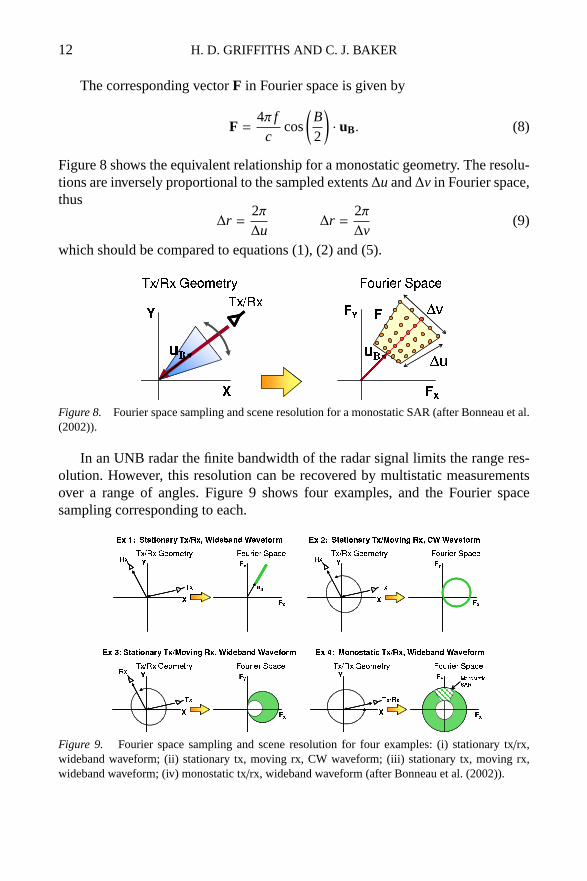
The corresponding vectorF in Fourier space is given by
F =4π f
ccos
(B2
)· uB. (8)
Figure 8 shows the equivalent relationship for a monostatic geometry. The resolu-tions are inversely proportional to the sampled extents∆u and∆v in Fourier space,thus
∆r =2π∆u
∆r =2π∆v
(9)
which should be compared to equations (1), (2) and (5).
Figure 8. Fourier space sampling and scene resolution for a monostatic SAR (after Bonneau et al.(2002)).
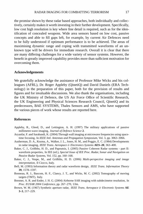
In an UNB radar the finite bandwidth of the radar signal limits the range res-olution. However, this resolution can be recovered by multistatic measurementsover a range of angles. Figure 9 shows four examples, and the Fourier spacesampling corresponding to each.
Figure 9. Fourier space sampling and scene resolution for four examples: (i) stationary tx/rx,wideband waveform; (ii) stationary tx, moving rx, CW waveform; (iii) stationary tx, moving rx,wideband waveform; (iv) monostatic tx/rx, wideband waveform (after Bonneau et al. (2002)).

RADAR IMAGING FOR COMBATTING TERRORISM 13
Recent experimental work under controlled conditions in anechoic chambers(Wicks et al. (2005), Wicks (2005)) and using turntable-mounted targets (Coetzeeet al., 2006) has demonstrated the validity of these theoretical approaches, andmay be expected to pave the way for more practical experiments and systems.
3.4. PASSIVE mm-WAVE IMAGING
Although not strictly a radar technique, one form of imaging that has shown signif-icant counterterrorism applications is passive mm-wave imaging. Here, an imageis formed at mm-wave frequencies (typically 35 or 94 GHz) of the thermal energyradiated or reflected from a target scene, in a similar way to thermal infrared imag-ing. However, the angular resolution (equation (2)) of an aperture of a given sizeis significantly poorer at mm-wave frequencies, so to achieve equivalent imageresolution a significantly larger sensor aperture is necessary. On the other hand,in contrast to thermal infrared imaging, the transmission properties of radiation atthese frequencies are such that mm-wave signals are not significantly attenuatedby obscurants such as smoke or fog, or in particular by clothing.
The image contrast is due to the difference between emissive sources whichappear warm (∼290 K) and reflective (metallic) objects which reflect cold sky(∼80 K at W-band) and hence which appear cold.
Figure 10. (left) MITRE passive mm-wave imager; (right upper) optical image from MalvernHills; (right lower) equivalent passive mm-wave image (courtesy of QinetiQ).
Figure 10 shows an example of an image obtained by a system of this kind,from the Malvern Hills in the west of the UK, on a summer day. Whilst the opticalimage is rather hazy, the mm-wave image is much clearer. The physical apertureof the imager is 1.2 m, giving an angular resolution at 94 GHz of∼2.5 mrad,and the image is formed by mechanical scanning of the antenna, taking severalseconds to build up the image. The receiver technology uses broad bandwidth low-noise amplifiers ahead of a detector; these achieve noise figures of a few dB andseveral tens of dB of gain, but the millimetre-wave MMICs requires specialisedfabrication facilities.

14 H. D. GRIFFITHS AND C. J. BAKER
More formally, we can write down an equation which relates the tempera-ture sensitivity∆T of a radiometer to the system noise temperatureTsys, the RFbandwidthB and the integration timeτ:
∆T =Tsys√
Bτ. (10)
The number of resolution cells (i.e. pixels)N is the product of the image widthXand image heightY, divided by the resolution cell sizeδ2:
N =XY
δ2. (11)
If the number of simultaneous beams (receivers) isn, then the image acquisitiontimeT is given by:
T =Nnτ (12)
and so
T =Nn·
1B
(Tsys
∆T
)2
. (13)
This demonstrates the tradeoffs involved in a passive mm-wave imaging system,and shows that if high-resolution images are to be obtained at operationally-usefulframe rates (T � 1 second), multiple receiver channels will be necessary. Severaltypes of scanning have been evaluated: mechanical, electronic, optical and digital.Some elegant forms of mechanical scanning have been devised (Appleby et al.,1997).
Figure 11. (left) passive mm-wave image of a person with a concealed weapon; (right)corresponding optical image (courtesy of QinetiQ, Malvern).

RADAR IMAGING FOR COMBATTING TERRORISM 15
In the context of counterterrorism the technique has shown great promise indetection of concealed weapons. Figure 11 shows an image of a person with aconcealed gun, and the corresponding optical image. When used indoors, someform of low-level noise illumination is needed. Figure 12 shows the result offusing an optical image (which would show the identity of the individual) witha passive mm-wave image.
Figure 12. Image fusion and detection (image courtesy Farran Technology 94GHz scanningsystem and ERA Technology).
3.5. PASSIVE BISTATIC RADAR
Although not strictly an imaging radar technique, there is considerable currentinterest in passive bistatic radar (PBR), making use of ‘illuminators of oppor-tunity’ such as broadcast, communications or radionavigation signals, rather thandedicated radar transmissions. Such illuminators - particularly VHF FM radio andUHF television - are high power and have very wide coverage, although digital ra-dio and television signals are more favourable in certain respects. Passive bistaticradar systems have several attractive features: (i) the radar system is passive, andhence undetectable (at least, by means of any radiated signal); (ii) reduced com-plexity and cost, since the transmit hardware already exists; (iii) it allows the useof frequency bands (VHF and UHF) which are not normally available for radaruse; and (iv) the bistatic geometry offers a counterstealth capability against certaintypes of target.
One type of threat for which passive bistatic radar systems may be particu-larly well suited is the defence of high-value assets such as government buildings,power stations or defence establishments against small airborne vehicles, such aslow-flying light aircraft, gliders or unmanned air vehicles (AUVs), which might

16 H. D. GRIFFITHS AND C. J. BAKER
carry explosive, chemical or biological warheads. Examples of incidents involvingsuch threats in recent years include the landing of a light aircraft in Red Square,Moscow, in 1987, the attack on the Pirellone Building in Milan, Italy, in May2002, and the landing of a light aircraft close to the White House in Washing-ton DC in May 2005 (Figure 13). Small air platforms of this kind will havemuch lower radar cross section than conventional aircraft, so although conven-tional surveillance radar systems may in principle give coverage of these areas,their ability to detect such low-signature targets may be somewhat limited. The
Figure 13. Three examples of incidents involving low-signature aircraft threats : (i) light aircraftlanding in Red Square, Moscow in 1987; (ii) Pirellone Building, Milan, 18 April 2002; (iii) WhiteHouse, Washington DC, 12 May 2005.
properties of illumination sources for passive bistatic radar, and the detectionperformance against different targets, have been evaluated and discussed (Bakeret al. (2005), Griffiths and Baker (2005a), Griffiths and Baker (2005b)). Detectionand tracking of conventional commercial aircraft (whose RCS would be of theorder of 20 dBm2) at ranges in excess of 100 km, using VHF FM radio transmis-sions, have been demonstrated, and these results can be extrapolated to predict theperformance against low signature targets of the type shown in Figure 13. Suchsystems would therefore be usable as ‘gap fillers’ for regions where the coverageof conventional surveillance sensors is inadequate, or to protect particular high-value assets. Another application might be against low-signature maritime targets,such as might be used to attack high-value naval targets, or for gun- or drug-running, although it is necessary to be sure that the illuminator coverage out tosea is adequate (Willis and Griffiths, 2007).
4. Future prospects
We have shown that there is a great deal of valuable information that can begleaned by using radar sensors. It is equally clear that alone they do not provide atrouble free route to reliable imaging, resulting in the detection of terrorist threats.Indeed as terrorists become more sophisticated they may well use jamming anddeception techniques, a topic that we have not even considered here. Nevertheless,
RADAR IMAGING FOR COMBATTING TERRORISM 17
the promise shown by these radar based approaches, both individually and collec-tively, certainly makes it worth investing in their further development. Specifically,low cost high resolution is key where fine detail is required, such as for the iden-tification of concealed weapons. Wide area sensors based on low cost, passiveconcepts and able to fill gaps left, for example, by current Air Defences needto be fully understood if optimum performance is to be achieved. The areas ofmaximising dynamic range and coping with transmitted waveforms of an un-known type will be drivers for immediate research. Overall it is clear that thereare many differing challenges for a wide variety of sensor systems. However, thebenefit in greatly improved capability provides more than sufficient motivation forovercoming them.
Acknowledgements
We gratefully acknowledge the assistance of Professor Mike Wicks and his col-leagues (AFRL), Dr. Roger Appleby (QinetiQ) and David Daniels (ERA Tech-nology) in the preparation of this paper, both for the provision of results andfigures and for invaluable discussions. We also thank the organisations, includingthe UK Ministry of Defence, the US Air Force Office of Scientific Research,the UK Engineering and Physical Sciences Research Council, QinetiQ and itspredecessors, BAE SYSTEMS, Thales Sensors and AMS, who have supportedthe various pieces of work whose results are reported here.
References
Appleby, R., Gleed, D., and Lettington, A. H. (1997) The military applications of passivemillimetre-wave imaging,Journal of Defence Science2.
Aryanfar, F. and Sarabandi, K. (2004) Through wall imaging at microwave frequencies using space-time focusing, InIEEE Intl. Antennas and Propagation Symposium, Vol. 3, pp. 3063–3066.
Ausherman, D. A., Kozma, A., Walker, J. L., Jones, H. M., and Poggio, E. C. (1984) Developmentsin radar imaging,IEEE Trans. Aerospace& Electronics SystemsAES–20, 363–400.
Baker, C. J., Griffiths, H. D., and Papoutsis, I. (2005) Passive Coherent Radar systems - part II:waveform properties, In IEE (ed.),Special Issue of IEE Proc. Radar, Sonar and Navigation onPassive Radar Systems, Vol. 152, pp. 160–168.
Baker, C. J., Vespe, M., and Griffiths, H. D. (2006)Multi-perspective imaging and imageinterpretation, Il Ciocco, Italy.
Bell, M. (1993) Information theory and radar waveform design,IEEE Trans. Information Theory39, 1578–1597.
Bonneau, R. J., Bascom, H. F., Clancy, J. T., and Wicks, M. C. (2002) Tomography of movingtargets (TMT), Italy.
Brenner, A. R. and Ender, J. H. G. (2004) Airborne SAR imaging with subdecimetre resolution, InProc. EUSAR 2004 Conference, pp. 267–270, Ulm.
Brown, W. M. (1967) Synthetic aperture radar,IEEE Trans. Aerospace& Electronic SystemsAE3–3, 217–229.

18 H. D. GRIFFITHS AND C. J. BAKER
Cantalloube, H. and Dubois-Fernandez, P. (2004) Airborne X-band SAR imaging with 10 cm res-olution - technical challenge and preliminary results, InProc. EUSAR 2004 Conference, pp.271–274, Ulm.
Carrara, W., Goodman, R. S., and Majewski, R. M. (1995)Spotlight Synthetic Aperture Radar:Signal Processing Algorithms, Artech House.
Coetzee, S., Baker, C. J., and Griffiths, H. D. (2006) Narrow band high resolution radar imaging, InProc. IEEE Radar Conference 2006, pp. 622–625, Verona, 24–27 April 2006.
Daniels, D. J. (2004)Ground Penetrating Radar (2nd edition), ISBN 0-86341-360-9, PeterPeregrinus, Stevenage.
Griffiths, H. D. and Baker, C. J. (2005)a ’Fundamentals of tomography and radar’ ’Bistatic andmultistatic sensors for homeland security’, InNATO Advanced Study Institute Advances inSensing with Security Applications, Il Ciocco, Italy, ISBN 1-4020-4286-8.
Griffiths, H. D. and Baker, C. J. (2005)b Passive Coherent Radar systems - part I: performanceprediction, In IEE (ed.),Special Issue of IEE Proc. Radar, Sonar and Navigation on PassiveRadar Systems, Vol. 152, pp. 153–159.
Howland, P. E., Maksimiuk, D., and Reitsma, G. (2005) FM radio based bistatic radar, In IEE(ed.),Special Issue of IEE Proc. Radar, Sonar and Navigation on Passive Radar Systems, pp.107–115, June 2005.
Knaell, K. K. and Cardillo, G. P. (1995) Radar tomography for the generation of three-dimensionalimages,IEE Proc. Radar, Sonar and Navigation on Passive Radar Systems142, 54–60.
Munson, D. C. J., O’Brien, J. D., and Jenkins, W. K. (1983) A tomographic formulation of spotlight-mode synthetic aperture radar, InProc. IEEE, Vol. 71, pp. 917–925.
Oliver, C. J. and Quegan, S. (1998)Understanding SAR Images, Artech House.Pasmurov, A. Y. and Zinoviev, Y. (2005)Radar Imaging and Tomography, Peter Peregrinus,
Stevenage.Sakamoto, T. and Sato, T. (1999) A target shape estimation algorithm for pulsed radar systems
based on boundary scattering transform, InIEICE Trans. Commun., Vol. E78–B.Soldovieri, F., Brancaccio, A., Leonore, G., and Pieri, R. (2005) Shape reconstruction of perfectly
conducting objects by multi view eperimental data,IEEE Trans. Geoscience& Remote Sensing43, 65–71.
Song, L.-P., Yu, C., and Liu, Q. H. (2005) Through-wall imaging (TWI) by radar: 2-D tomographicresults and analyses,IEEE Trans. Geoscience and Remote Sensing43, 2793–2798, December2005.
Soumekh, M. (1999)Synthetic Aperture Radar Signal Processing with MatLab Algorithms, ArtechHouse.
http://www.darpa.mil/baa/baa06-04.html.Vespe, M., Baker, C. J., and Griffiths, H. D. (2005) Multi-perspective target classification, InProc.
RADAR 2005 Conference, pp. 877–882, IEEE Publ. No. 05CH37628, Washington DC, 9-12May 2005.
Walker, J. L. (1980) Range Doppler imaging of rotating objects,IEEE Trans. Aerospace&Electronics Systems16, 23–52.
Wehner, D. R. (1987)High Resolution Radar, Artech House.Wicks, M. (2005) Tomography, Waveform Diversity and Intelligent Systems, InAOC Fourth
Multinational Conference on Passive and Covert Radar, Syracuse, 5-7 October 2005.Wicks, M. C., Himed, B., Bascom, H., and Clancy, J. (2005) Tomography of Moving Targets (TMT)
for security and surveillance, InNATO Advanced Study Institute Advances in Sensing withSecurity Applications, Il Ciocco, Italy, ISBN 1-4020-4286-8.
Wiley, C. A. (1985) Synthetic Aperture Radars - a paradigm for technology evolution,IEEE Trans.Aerospace& Electronic SystemsAES–21, 440–443.

RADAR IMAGING FOR COMBATTING TERRORISM 19
Willis, N. and Griffiths, H. D. (2007)(eds), Advances in Bistatic Radar, to be published by SciTech,2007.
Yang, Y. and Fathy, A. E. (2005) See-through-wall imaging using ultra wideband short-pulse radarsystem, InIEEE Intl. Antennas and Propagation Symposium, Vol. 3B, pp. 334–337, 3–8 July2005.