radiator valves ven2… vun2…
TRANSCRIPT
2106
EN 215-1
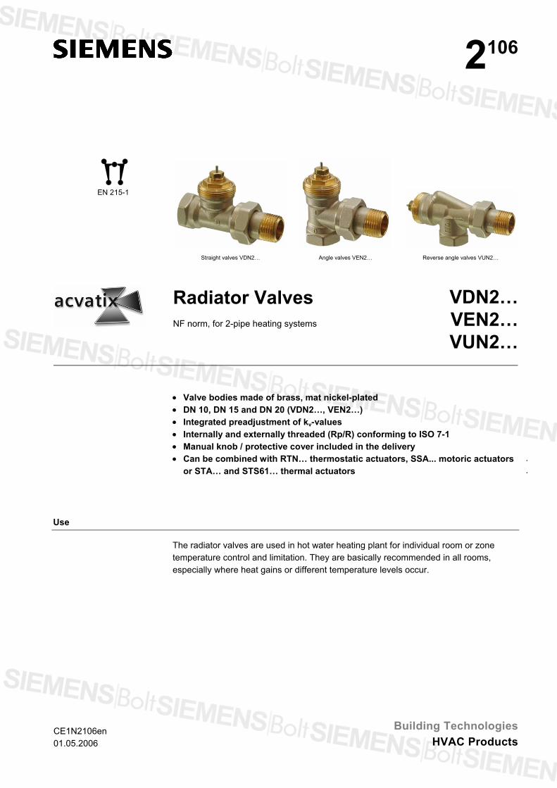
Straight valves VDN2… Angle valves VEN2… Reverse angle valves VUN2…
Radiator Valves NF norm, for 2-pipe heating systems
VDN2…VEN2…VUN2…
• Valve bodies made of brass, mat nickel-plated • DN 10, DN 15 and DN 20 (VDN2…, VEN2…) • Integrated preadjustment of kv-values • Internally and externally threaded (Rp/R) conforming to ISO 7-1 • Manual knob / protective cover included in the delivery
.
.• Can be combined with RTN… thermostatic actuators, SSA... motoric actuators
or STA… and STS61… thermal actuators
Use
The radiator valves are used in hot water heating plant for individual room or zone temperature control and limitation. They are basically recommended in all rooms, especially where heat gains or different temperature levels occur.
CE1N2106en 01.05.2006
Building TechnologiesHVAC Products
Type summary
Type reference straight
Type referenceangle
Type referencereverse angle
DN kv-value [m3/h) setting range
kv-value [m3/h) at a P-band of 2 K
VDN210 VEN210 0.09…0.63
VUN210 10
0.14…0.60 0.43
VDN215 VEN215 0.10…0.89
VUN215 15
0.13…0.77 0.52
VDN220 VEN220 20 0.31…1.41 0.71
Order When ordering, please give quantity, product name and type reference.
Example: 2 straight valves VDN220 1 protection against dismantling ATN2
Delivery Valves and accessories are packed separately.
Equipment combinations
.
.
.
.
.
.
.
Product Types Data sheet Thermostatic actuators RTN... N2111
Motoric actuators SSA31… / SSA61… / SSA81… N4893
Thermal actuators STA21… / STA71… N4877
Thermal actuators STA72E… N4875
Thermal actuators STS61… 1) N4880
1) Quasi-proportional control action, not recommended for parallel operation
Mechanical design / technical design
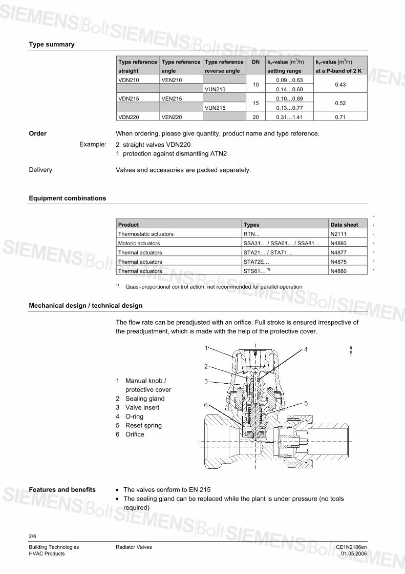
The flow rate can be preadjusted with an orifice. Full stroke is ensured irrespective of the preadjustment, which is made with the help of the protective cover.
1 Manual knob / protective cover
2 Sealing gland 3 Valve insert 4 O-ring 5 Reset spring 6 Orifice
• The valves conform to EN 215 Features and benefits • The sealing gland can be replaced while the plant is under pressure (no tools
required)
2/8
Building Technologies Radiator Valves CE1N2106en HVAC Products 01.05.2006
.
.
.
.
.
.
.
.
.
.
.
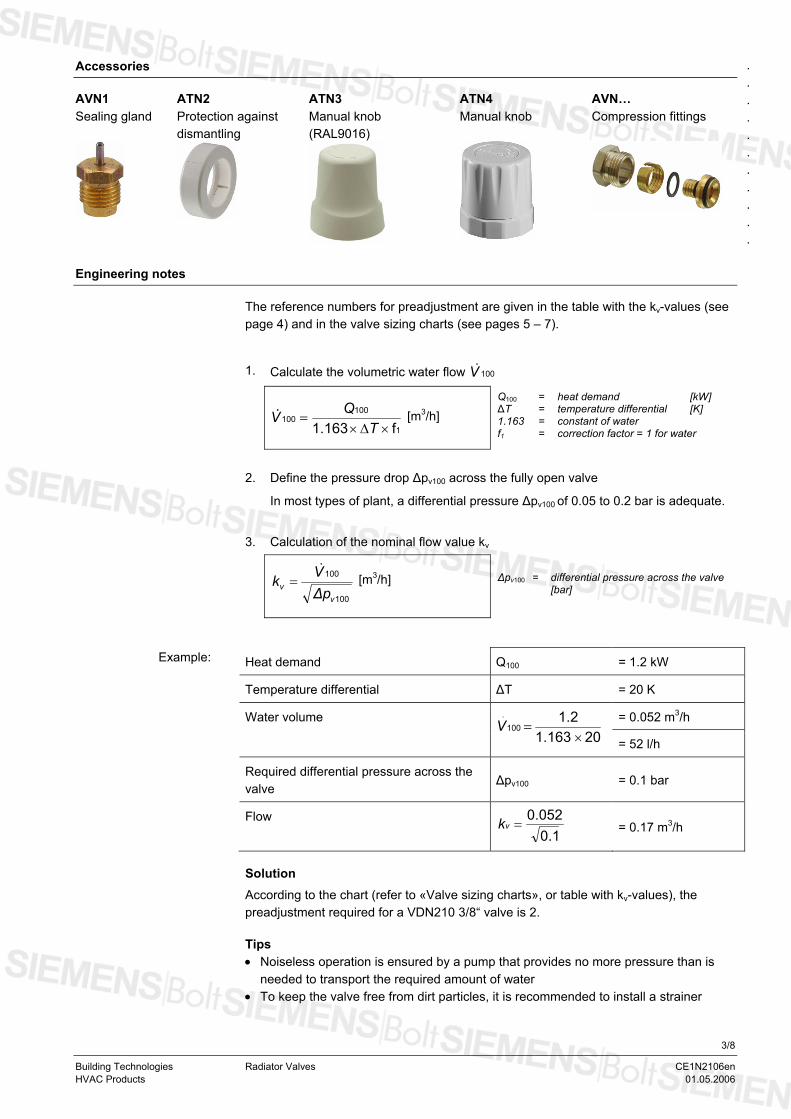
Accessories
AVN1 Sealing gland
ATN2 Protection against dismantling
ATN3 Manual knob (RAL9016)
ATN4 Manual knob
AVN… Compression fittings
Engineering notes
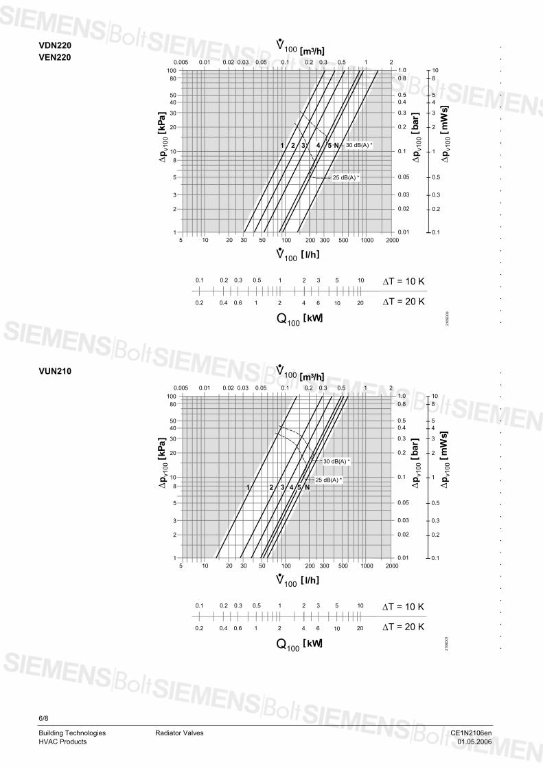
The reference numbers for preadjustment are given in the table with the kv-values (see page 4) and in the valve sizing charts (see pages 5 – 7). 1. Calculate the volumetric water flow 100V&
1
100100
f1.163.
×∆×=
TQV [m3/h]
Q100 = heat demand [kW] ∆T = temperature differential [K] 1.163 = constant of water f1 = correction factor = 1 for water
2. Define the pressure drop ∆pv100 across the fully open valve
In most types of plant, a differential pressure ∆pv100 of 0.05 to 0.2 bar is adequate.
3. Calculation of the nominal flow value kv
100
100
vv ∆p
Vk&
= [m3/h] ∆pv100 = differential pressure across the valve [bar]
Heat demand Q100 = 1.2 kW
Temperature differential ∆T = 20 K
Water volume = 0.052 m3/h
20 1.1631.2.
100×
=V = 52 l/h
Required differential pressure across the valve
∆pv100 = 0.1 bar
Flow 0.1
0.052=vk = 0.17 m3/h
Example:
Solution According to the chart (refer to «Valve sizing charts», or table with kv-values), the preadjustment required for a VDN210 3/8“ valve is 2. Tips • Noiseless operation is ensured by a pump that provides no more pressure than is
needed to transport the required amount of water • To keep the valve free from dirt particles, it is recommended to install a strainer
3/8
Building Technologies Radiator Valves CE1N2106en HVAC Products 01.05.2006
The kv-value gives the volumetric water flow in m100V.
3/h at a pressure drop ∆pv100 across the valve of 1 bar.
kv-values
Control range with SSA…, STA… actuators and STS61…
Control range of thermostatic actuators RTN…
Reference numbers for preadjustment
1 2 3 4 5 N N1)
VDN210 / VEN210 0.09 0.18 0.26 0.33 0.48 0.63 0.43
VDN215 / VEN215 0.10 0.20 0.31 0.45 0.69 0.89 0.52
VDN220 / VEN220 0.31 0.41 0.54 0.83 0.91 1.41 0.71
VUN210 0.14 0.28 0.38 0.49 0.53 0.60 0.43
VUN215 0.13 0.23 0.34 0.52 0.66 0.77 0.50
kv-values [m3/h] at the different preset positions
1) kV-value at a P-band of 2 K
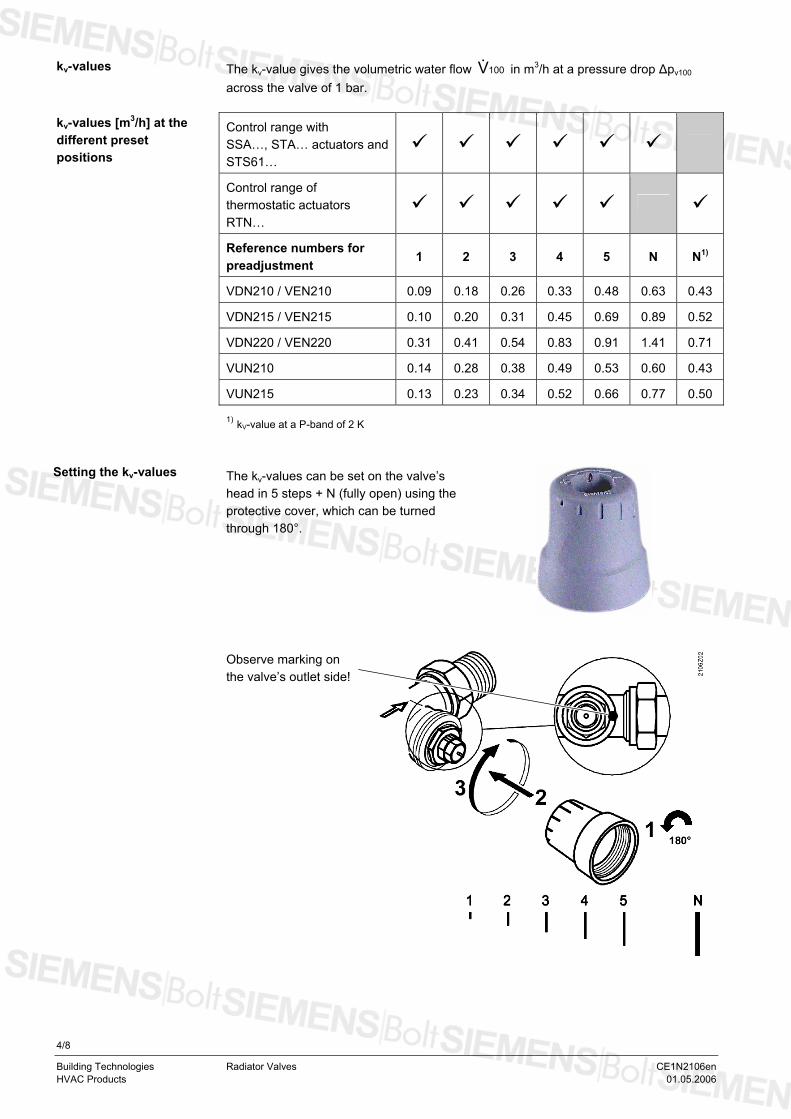
Setting the kv-values The kv-values can be set on the valve’s head in 5 steps + N (fully open) using the protective cover, which can be turned through 180°.
Observe marking on the valve’s outlet side!
4/8
Building Technologies Radiator Valves CE1N2106en HVAC Products 01.05.2006
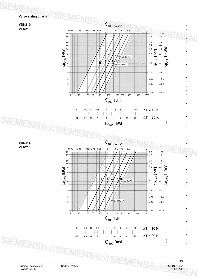
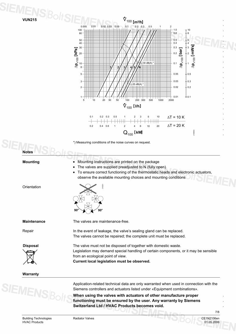
Valve sizing charts
[ kPa
]
1.08
54
3
2
10
0.5
0.3
0.2
1
0.1
80
5040
30
20
100
8
5
3
2
10
120 30 50 10010 200 300 500 1000 2000
0.8
0.50.4
0.3
0.2
0.05
0.03
0.02
0.1
0.01
∆p v
100
2105
D01
[ l/h ]5
[ m /h ]3
21 3 54 N
0.005 0.01 0.02 0.03 0.05 0.1 0.2 0.3 0.5 1 2
V100
[ bar
]∆
p v10
0
[ mW
s ]∆
p v10
0
V100
0.2 0.3 0.5 10.1 2 3 5 10
0.4 0.6 1 20.2 4 6 10 20
[ kW ]Q100
∆T = 10 K
∆T = 20 K
30 dB(A) *
25 dB(A) *
.
.
.
.
.
.
.
.
.
.
.
.
.
.
.
.
.
.
.
.
.
.
.
.
VDN210 VEN210
[ kPa
]
1.08
54
3
2
10
0.5
0.3
0.2
1
0.1
80
5040
30
20
100
8
5
3
2
10
120 30 50 10010 200 300 500 1000 2000
0.8
0.50.4
0.3
0.2
0.05
0.03
0.02
0.1
0.01
∆p v
100
2105
D02
[ l/h ]5
[ m /h ]3
0.005 0.01 0.02 0.03 0.05 0.1 0.2 0.3 0.5 1 2
V100
[ bar
]∆
p v10
0
[ mW
s ]∆
p v10
0
V100
21 4 5 N
0.2 0.3 0.5 10.1 2 3 5 10
0.4 0.6 1 20.2 4 6 10 20
[ kW ]Q100
∆T = 10 K
∆T = 20 K
30 dB(A) *
25 dB(A) *
3
.
.
.
.
.
.
.
.
.
.
.
.
.
.
.
.
.
.
.
.
.
.
.
.
VDN215 VEN215
5/8
Building Technologies Radiator Valves CE1N2106en HVAC Products 01.05.2006
[ kPa
]
1.08
54
3
2
10
0.5
0.3
0.2
1
0.1
80
5040
30
20
100
8
5
3
2
10
120 30 50 10010 200 300 500 1000 2000
0.8
0.50.4
0.3
0.2
0.05
0.03
0.02
0.1
0.01
∆p v
100
2105
D03
[ l/h ]5
[ m /h ]3
0.005 0.01 0.02 0.03 0.05 0.1 0.2 0.3 0.5 1 2
V100
[ bar
]∆
p v10
0
[ mW
s ]∆
p v10
0
V100
432
0.2 0.3 0.5 10.1 2 3 5 10
0.4 0.6 1 20.2 4 6 10 20
[ kW]Q100
∆T = 10 K
∆T = 20 K
1 30 dB(A) *
25 dB(A) *
5 N
.
.
.
.
.
.
.
.
.
.
.
.
.
.
.
.
.
.
.
.
.
.
.
.
VDN220 VEN220
[ kPa
]
1.08
54
3
2
10
0.5
0.3
0.2
1
0.1
80
5040
30
20
100
8
5
3
2
10
120 30 50 10010 200 300 500 1000 2000
0.8
0.50.4
0.3
0.2
0.05
0.03
0.02
0.1
0.01
∆p v
100
2106
D01
[ l/h ]5
[ m /h ]3
0.005 0.01 0.02 0.03 0.05 0.1 0.2 0.3 0.5 1 2
V100
[ bar
]∆
p v10
0
[ mW
s ]∆
p v10
0
V100
0.2 0.3 0.5 10.1 2 3 5 10
0.4 0.6 1 20.2 4 6 10 20
[ kW ]Q100
∆T = 10 K
∆T = 20 K
30 dB(A) *
25 dB(A) *N4321 5
.
.
.
.
.
.
.
.
.
.
.
.
.
.
.
.
.
.
.
.
.
.
.
.
VUN210
6/8
Building Technologies Radiator Valves CE1N2106en
HVAC Products 01.05.2006
[ kPa
]
1.08
54
3
2
10
0.5
0.3
0.2
1
0.1
80
5040
30
20
100
8
5
3
2
10
120 30 50 10010 200 300 500 1000 2000
0.8
0.50.4
0.3
0.2
0.05
0.03
0.02
0.1
0.01
∆p v
100
2106
D02
[ l/h ]5
[ m /h ]3
0.005 0.01 0.02 0.03 0.05 0.1 0.2 0.3 0.5 1 2
V100
[ bar
]∆
p v10
0
[ mW
s ]∆
p v10
0
V100
N54321
0.2 0.3 0.5 10.1 2 3 5 10
0.4 0.6 1 20.2 4 6 10 20
[ kW ]Q100
∆T = 10 K
∆T = 20 K
30 dB(A) *
25 dB(A) *
.
.
.
.
.
.
.
.
.
.
.
.
.
.
.
.
.
.
.
.
.
.
.
VUN215
*) Measuring conditions of the noise curves on request.
Notes
• Mounting Instructions are printed on the package Mounting • The valves are supplied preadjusted to N (fully open) • To ensure correct functioning of the thermostatic heads and electronic actuators,
observe the available mounting choices and mounting conditions
90°
2105
Z01
90°
Orientation
Maintenance The valves are maintenance-free.
Repair In the event of leakage, the valve’s sealing gland can be replaced.
The valves cannot be repaired; the complete unit must be replaced.
Disposal
The valve must not be disposed of together with domestic waste. Legislation may demand special handling of certain components, or it may be sensible from an ecological point of view. Current local legislation must be observed.
Warranty
Application-related technical data are only warranted when used in connection with the Siemens controllers and actuators listed under «Equipment combinations».
.
.
.
When using the valves with actuators of other manufacture proper functioning must be ensured by the user. Any warranty by Siemens Switzerland Ltd / HVAC Products becomes void.
7/8
Building Technologies Radiator Valves CE1N2106en HVAC Products 01.05.2006
Technical data
.
.
.
.
.
.
.
.
.
.
.
.
.
.
.
.
.
.
.
.
Functional data PN class PN 10 Suitable media 1) cold and low-temperature hot water, water with
propylene-glycol, water with ethylene-glykol < 30%; recommendation: water treatment to VDI 2035
Medium temperature 1…120 °C Perm. operating pressure 1000 kPa (10 bar) Differential pressure ∆pmax max. 60 kPa (0.6 bar) Differential pressure ∆pv100 5…20 kPa (0.05…0.2 bar): recommended range Stroke min 1.2 mm Materials Valve body brass, mat nickel-plated Fitting brass, mat nickel-plated Protective cover polypropylene O-ring EPDM, NBR Dimensions / weight Refer to «Dimensions» Mounting length EN 215 Thread Rp internally threaded
R externally threaded G-thread
to ISO 7-1 to ISO 7-1 to ISO 228-1
1) Prefer propylene-glycol for environment protection reasons.
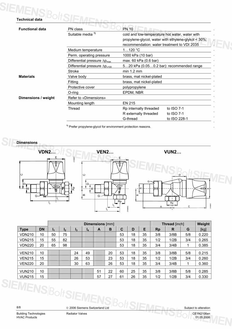
Dimensions
VDN2… VEN2… VUN2…
l2
CD
2106
M01E
G
RpR
l1
l4
DC
E
B G
2106
M02
Rp
R
l3
A C
B
2106
M03
G
Rp
R E
Dimensions [mm] Thread [inch] WeightType DN l1 l2 l3 l4 A B C D E Rp R G [kg] VDN210 10 50 75 53 18 35 3/8 3/8B 5/8 0.220 VDN215 15 55 82 53 18 35 1/2 1/2B 3/4 0.265 VDN220 20 65 98 53 18 35 3/4 3/4B 1 0.385
VEN210 10 24 49 20 53 18 35 3/8 3/8B 5/8 0.215 VEN215 15 26 53 23 53 18 35 1/2 1/2B 3/4 0.260 VEN220 20 30 63 26 53 18 35 3/4 3/4B 1 0.360
VUN210 10 51 22 60 25 35 3/8 3/8B 5/8 0.285 VUN215 15 57 27 61 26 35 1/2 1/2B 3/4 0.330
8/8
Building Technologies HVAC Products
Radiator Valves CE1N2106en
© 2006 Siemens Switzerland Ltd Subject to alteration
01.05.2006