review article harmonic mitigation techniques applied to...
TRANSCRIPT

Hindawi Publishing CorporationAdvances in Power ElectronicsVolume 2013, Article ID 591680, 10 pageshttp://dx.doi.org/10.1155/2013/591680
Review ArticleHarmonic Mitigation Techniques Applied toPower Distribution Networks
Hussein A. Kazem
Faculty of Engineering, Sohar University, P.O. Box 44, 311 Sohar, Oman
Correspondence should be addressed to Hussein A. Kazem; [email protected]
Received 30 July 2012; Revised 20 January 2013; Accepted 21 January 2013
Academic Editor: Hadi Y. Kanaan
Copyright © 2013 Hussein A. Kazem. This is an open access article distributed under the Creative Commons Attribution License,which permits unrestricted use, distribution, and reproduction in any medium, provided the original work is properly cited.
A growing number of harmonic mitigation techniques are now available including active and passive methods, and the selectionof the best-suited technique for a particular case can be a complicated decision-making process. The performance of some of thesetechniques is largely dependent on system conditions, while others require extensive system analysis to prevent resonance problemsand capacitor failure. A classification of the various available harmonic mitigation techniques is presented in this paper aimedat presenting a review of harmonic mitigation methods to researchers, designers, and engineers dealing with power distributionsystems.
1. Introduction
The nonlinear characteristics of many industrial and com-mercial loads such as power converters, fluorescent lamps,computers, light dimmers, and variable speed motor drives(VSDs) used in conjunction with industrial pumps, fans,and compressors and also in air-conditioning equipmenthave made the harmonic distortion a common occurrencein electrical power networks. Harmonic currents injected bysome of these loads are usually too small to cause a significantdistortion in distribution networks. However, when operat-ing in large numbers, the cumulative effect has the capabilityof causing serious harmonic distortion levels. These do notusually upset the end-user electronic equipment as much asthey overload neutral conductors and transformers and, ingeneral, cause additional losses and reduced power factor [1–5]. Large industrial converters and variable speed drives onthe other hand are capable of generating significant levels ofdistortion at the point of common coupling (PCC), whereother users are connected to the network [6, 7].
Because of the strict requirement of power quality at theinput AC mains, various harmonic standards and engineer-ing recommendations such as IEC 1000-3-2, IEEE 519 (USA),AS 2279, D.A.CH.CZ, EN 61000-3-2/EN 61000-3-12, and ERG5/4 (UK) are employed to limit the level of distortion at thePCC. To comply with these harmonic standards, installationsutilizing power electronic and nonlinear loads often use one
of the growing numbers of harmonic mitigation techniques[8]. Because of the number and variety of available methods,the selection of the best-suited technique for a particularapplication is not always an easy or straightforward process.Many options are available, including active and passivemethods. Some of the most technically advanced solutionsoffer guaranteed results and have little or no adverse effecton the isolated power system, while the performance ofother simple methods may be largely dependent on systemconditions. This paper presents a comprehensive survey onharmonic mitigation techniques in which a large numberof technical publications have been reviewed and used toclassify harmonicmitigation techniques into three categories:passive techniques, active techniques, and hybrid harmonicreduction techniques using a combination of active and pas-sive methods. A brief description of the electrical character-istics of each method is presented with the aim of providingthe designer and site engineer with a more informed choiceregarding their available optionswhendealingwith the effectsand consequences of the presence of these harmonics in thedistribution network.
2. Passive Harmonic Mitigation Techniques
Many passive techniques are available to reduce the level ofharmonic pollution in an electrical network, including the

2 Advances in Power Electronics
Optional
Switchmodepowersupply
DCload𝑉𝑠
𝑅𝑠𝐿𝑠
𝑉in
𝐶in 𝐶dc
𝐿𝑐
(a)
𝐿𝑟
𝐸𝑖𝐶𝑟 𝐶dc
D1
D2
D3
D4
𝑅𝐿 𝑉𝐿
Load𝐼𝑖
𝐼𝐿
(b)
𝐼𝐿𝐼𝑖
𝐿𝑟
𝐸𝑖𝐶𝑟 𝐶dc
D1
D2
D3
D4
𝑅𝐿 𝑉𝐿𝐶𝑏
Load
(c)
𝐿𝑟
𝐸𝑖𝐶𝑟 𝐶dc
D1
D2
D3
D4
𝑅𝐿 𝑉𝐿𝐶𝑏
𝐿𝑜
Load
𝐼𝐿𝐼𝑖
(d)
Figure 1: (a)The Series inductor filters for current shaping, (b)The Ziogas inductor capacitor filter, (c)The Yanchao improvement on Ziogasfilter, and (d) The Hussein improvement on Yanchao filter.
D
Switchmodepowersupply
DCload
Boost converter𝐿𝑐
𝑉𝑠
𝑅𝑠𝐿𝑠
𝑉in
𝐶dc
𝑏
𝑆𝑏
(a)
𝐶dc
D1
D2
D3
D4
𝑅𝐿
𝐿1 𝐿2
𝐶1
𝑄
𝑉𝑠
𝐼𝑖
(b)
𝑉𝑠
D1
D2
D3
D4
D5 D6
𝐿r1 𝐿r2
𝑆𝑃
𝐿
𝑅shunt
𝐶dc𝑉𝐿
𝑅𝐿
𝑆𝑎
PWM control
Load𝐼𝑖
𝐼𝐿
(c)
𝐿1 𝐿2
𝐶dc
D1
D2
D3
D4
𝑅𝐿𝑉𝑠 𝐶1
𝑄
𝐷a1𝑄a1
𝑄a2 𝐷a2
𝐼𝑖
(d)
Figure 2: (a) Boost converter current shaping circuit, (b) buck converter current shaping circuit, (c) improve boost converter current shapingcircuit, and (d) improve buck converter current shaping circuit.
Advances in Power Electronics 3
Rectifier+
switchmodepowersupply
𝑉𝑠
𝑅𝑠𝐿𝑠
𝑖𝑠𝐿𝑓
𝐿𝑟
𝐶𝑟
𝑉in𝑖in
𝑖Lr
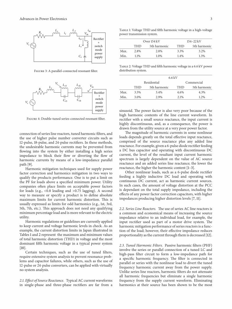
Figure 3: A parallel-connected resonant filter.
Rectifier+
switchmodepowersupply
𝑉𝑠
𝑅𝑠
𝑉𝑖𝑉in
𝐿r3 𝐿rh
𝐶r3 𝐶rh
𝐿𝑠
Figure 4: Double-tuned series-connected resonant filter.
connection of series line reactors, tuned harmonic filters, andthe use of higher pulse number converter circuits such as12-pulse, 18-pulse, and 24-pulse rectifiers. In these methods,the undesirable harmonic currents may be prevented fromflowing into the system by either installing a high seriesimpedance to block their flow or diverting the flow ofharmonic currents by means of a low-impedance parallelpath [9].
Harmonic mitigation techniques used for supply powerfactor correction and harmonics mitigation in two ways toqualify the products performance. One is to put a limit onthe PF for loads above a specified minimum power. Utilitycompanies often place limits on acceptable power factorsfor loads (e.g., <0.8 leading and >0.75 lagging). A secondway to measure or specify a product is to define absolutemaximum limits for current harmonic distortion. This isusually expressed as limits for odd harmonics (e.g., 1st, 3rd,5th, 7th, etc.). This approach does not need any qualifyingminimumpercentage load and ismore relevant to the electricutility.
Harmonic regulations or guidelines are currently appliedto keep current and voltage harmonic levels in check. As anexample, the current distortion limits in Japan illustrated inTables 1 and 2 represent the maximum and minimum valuesof total harmonic distortion (THD) in voltage and the mostdominant fifth harmonic voltage in a typical power system[10].
Certain techniques, such as the use of tuned filters,require extensive system analysis to prevent resonance prob-lems and capacitor failures, while others, such as the use of12-pulse or 24-pulse converters, can be applied with virtuallyno system analysis.
2.1. Effect of Source Reactance. Typical AC current waveformsin single-phase and three-phase rectifiers are far from a
Table 1: Voltage THD and fifth harmonic voltage in a high-voltagepower transmission system.
Over 154 kV 154–22 kVTHD 5th harmonic THD 5th harmonic
Max. 2.8% 2.8% 3.3% 3.2%Min. 1.1% 1.0% 1.4% 1.3%
Table 2: Voltage THD and fifth harmonic voltage in a 6.6 kV powerdistribution system.
6.6 kVResidential Commercial
THD 5th harmonic THD 5th harmonicMax. 3.5% 3.4% 4.6% 4.3%Min. 3.0% 2.9% 2.1% 1.2%
sinusoid. The power factor is also very poor because of thehigh harmonic contents of the line current waveform. Inrectifier with a small source reactance, the input current ishighly discontinuous, and, as a consequence, the power isdrawn from the utility source at a very poor power factor.
The magnitude of harmonic currents in some nonlinearloads depends greatly on the total effective input reactance,comprised of the source reactance plus any added linereactance. For example, given a 6-pulse diode rectifier feedinga DC bus capacitor and operating with discontinuous DCcurrent, the level of the resultant input current harmonicspectrum is largely dependent on the value of AC sourcereactance and an added series line reactance; the lower thereactance, the higher the harmonic content [1–3].
Other nonlinear loads, such as a 6-pulse diode rectifierfeeding a highly inductive DC load and operating withcontinuous DC current, act as harmonic current sources.In such cases, the amount of voltage distortion at the PCCis dependant on the total supply impedance, including theeffects of any power factor correction capacitors, with higherimpedances producing higher distortion levels [7, 11].
2.2. Series Line Reactors. The use of series AC line reactors isa common and economical means of increasing the sourceimpedance relative to an individual load, for example, theinput rectifier used as part of a motor drive system. Theharmonicmitigation performance of series reactors is a func-tion of the load; however, their effective impedance reducesproportionality as the current through them is decreased [12].
2.3. Tuned Harmonic Filters. Passive harmonic filters (PHF)involve the series or parallel connection of a tuned LC andhigh-pass filter circuit to form a low-impedance path fora specific harmonic frequency. The filter is connected inparallel or series with the nonlinear load to divert the tunedfrequency harmonic current away from the power supply.Unlike series line reactors, harmonic filters do not attenuateall harmonic frequencies but eliminate a single harmonicfrequency from the supply current waveform. Eliminatingharmonics at their source has been shown to be the most
4 Advances in Power Electronics
effective method to reduce harmonic losses in the isolatedpower system. However, the increased first cost entailedpresents a barrier to this approach. If the parallel-connectedfilter is connected further upstream in the power network,higher day-to-day costs will accumulate due to 𝐼2𝑅 losses inthe conductors and other plant items that carry the harmoniccurrents. Conversely, for series-connected filter at the load,there are increased losses in the filter itself. These losses aresimply the result of the higher series impedance, which blocksthe flow of harmonics but increases the line loss as a resultof the flow of the remaining components of the load current[12, 13]. The quality factor of the filter inductor 𝑄 affects theactual value of the low-impedance path for each filter. Usually,a value of 𝑄 ranges between 20 and 100 [14]. Many typesof harmonic filters are commonly employed, including thefollowing:
2.3.1. Series Induction Filters. Harmonic currents producedby switched-mode power supplies and other DC-to-DC con-verter circuits can be significantly lowered by the connectionof a series inductor that can be added on either the AC orDC power circuit [15–17], as shown in Figure 1. So manyimprovements on these filters have been made.
Ziogas passive filter for single-phase rectifiers has somereduction in Total Harmonics Distortion THD and improve-ment in PF in comparison with conventional rectifier. Also,Yanchoa waveshaping filter used to reduce THD and increasepower factor. Connecting author filter at the output terminalof the rectifier will improve power factor and reduce inputcurrent THD of the supply.
2.3.2. DC-DC Converter Current Shaping. Like the seriesinduction filter, this circuit (Figure 2) can greatly reducecurrent distortion produced by switched-mode power sup-plies and other DC converter circuits by modulating theduty cycle of switch 𝑆
𝑏to control the shape of input supply
current to track a desired sine waveshape [5, 18–20]. So manyimprovements on these filters have been made.
2.3.3. Parallel-Connected Resonant Filter. Passive LC filterstuned to eliminate a particular harmonic are often usedto reduce the level of low-frequency harmonic componentslike the 5th and 7th produced by three-phase rectifier andinverter circuits. The filter is usually connected across theline as shown in Figure 3. If more than one harmonic isto be eliminated, then a shunt filter must be installed foreach harmonic. Care must be taken to ensure that the peakimpedances of such an arrangement are tuned to frequenciesbetween the required harmonic frequencies to avoid causinghigh levels of voltage distortion at the supply’s PCC becauseof the presence of an LC resonance circuit [7, 12].
2.3.4. Series-Connected Resonant Filter. This work on a sim-ilar in principle to the parallel version, but with the tuned𝐿𝐶 circuits connected in series with the supply. The seriesfilter can be tuned to a single harmonic frequency, or itmay be multituned to a number of harmonic frequencies.The multituned arrangement connects multiple tuned filters
Rectifier+
SMPS
Rectifier+
SMPS
Rectifier+
SMPS𝑅𝑟
𝐿𝑟
𝐶𝑟
𝑉as 𝑅as 𝐿as 𝑖a-in
𝑉bs 𝑅bs 𝐿bs 𝑖b-in
𝑉cs 𝑅cs𝐿cs 𝑖c-in
𝑉c-in
𝑉a-in
𝑉b-in
Neutral harmonicblocking filter
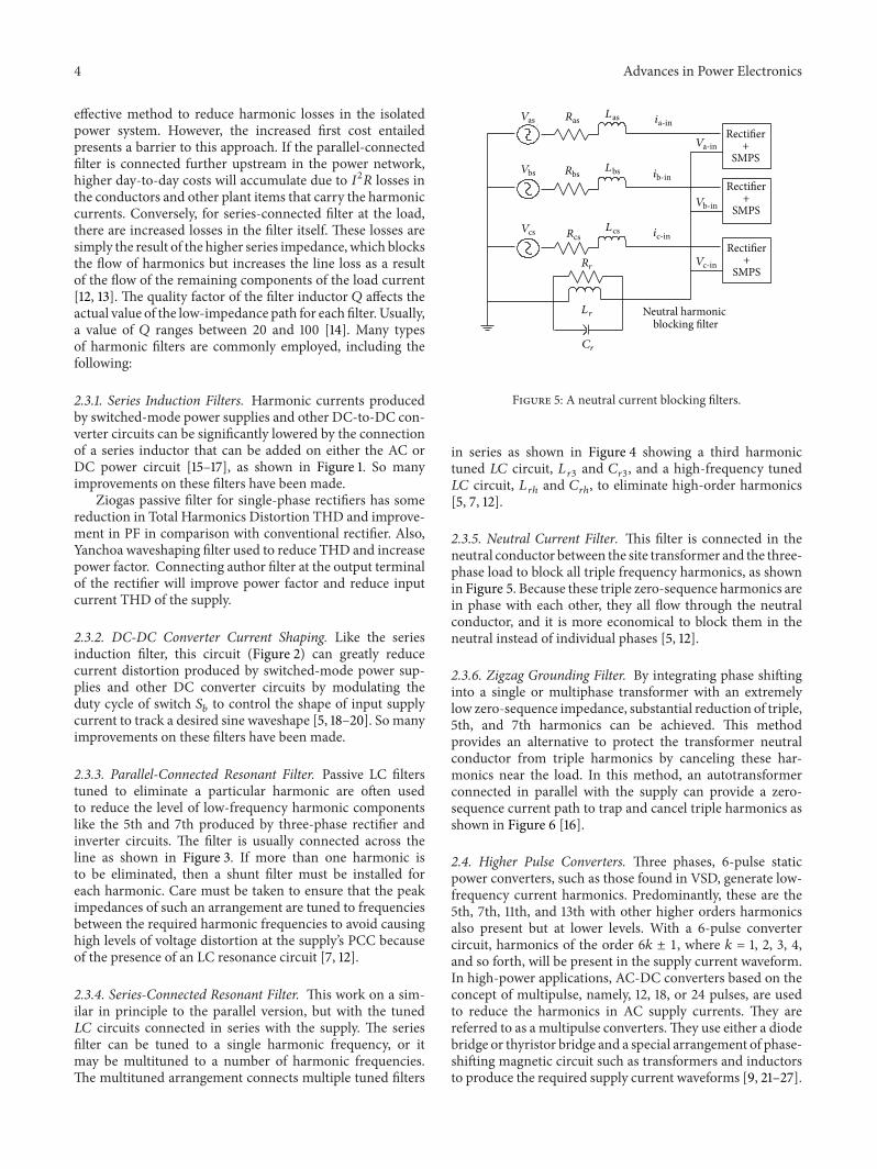
Figure 5: A neutral current blocking filters.
in series as shown in Figure 4 showing a third harmonictuned 𝐿𝐶 circuit, 𝐿
𝑟3and 𝐶
𝑟3, and a high-frequency tuned
𝐿𝐶 circuit, 𝐿𝑟ℎ
and 𝐶𝑟ℎ, to eliminate high-order harmonics
[5, 7, 12].
2.3.5. Neutral Current Filter. This filter is connected in theneutral conductor between the site transformer and the three-phase load to block all triple frequency harmonics, as shownin Figure 5. Because these triple zero-sequence harmonics arein phase with each other, they all flow through the neutralconductor, and it is more economical to block them in theneutral instead of individual phases [5, 12].
2.3.6. Zigzag Grounding Filter. By integrating phase shiftinginto a single or multiphase transformer with an extremelylow zero-sequence impedance, substantial reduction of triple,5th, and 7th harmonics can be achieved. This methodprovides an alternative to protect the transformer neutralconductor from triple harmonics by canceling these har-monics near the load. In this method, an autotransformerconnected in parallel with the supply can provide a zero-sequence current path to trap and cancel triple harmonics asshown in Figure 6 [16].
2.4. Higher Pulse Converters. Three phases, 6-pulse staticpower converters, such as those found in VSD, generate low-frequency current harmonics. Predominantly, these are the5th, 7th, 11th, and 13th with other higher orders harmonicsalso present but at lower levels. With a 6-pulse convertercircuit, harmonics of the order 6𝑘 ± 1, where 𝑘 = 1, 2, 3, 4,and so forth, will be present in the supply current waveform.In high-power applications, AC-DC converters based on theconcept of multipulse, namely, 12, 18, or 24 pulses, are usedto reduce the harmonics in AC supply currents. They arereferred to as a multipulse converters.They use either a diodebridge or thyristor bridge and a special arrangement of phase-shifting magnetic circuit such as transformers and inductorsto produce the required supply current waveforms [9, 21–27].
Advances in Power Electronics 5
Rectifier+
SMPS
Rectifier+
SMPS
Rectifier+
SMPS
𝑉as𝐿as
𝑖as
𝑉a1 𝑉a2
𝑉bs𝐿bs
𝑖bs
𝑉b1 𝑉b2
𝑉cs𝐿cs 𝑖cs
𝑉c1 𝑉c2 𝑖𝑛
𝑖a-in
𝑛
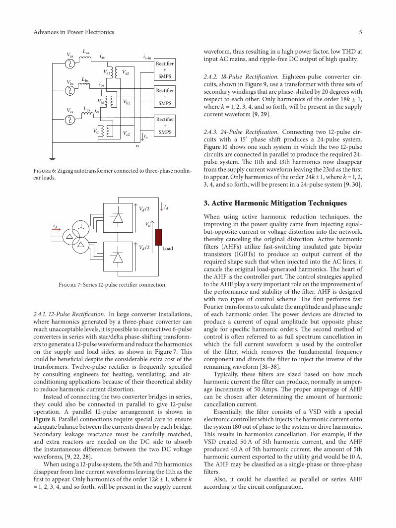
Figure 6: Zigzag autotransformer connected to three-phase nonlin-ear loads.
Load
𝑖𝐴𝑉𝑑
𝐼𝑑𝑉𝑑/2
𝑉𝑑/2
Figure 7: Series 12-pulse rectifier connection.
2.4.1. 12-Pulse Rectification. In large converter installations,where harmonics generated by a three-phase converter canreach unacceptable levels, it is possible to connect two 6-pulseconverters in series with star/delta phase-shifting transform-ers to generate a 12-pulsewaveformand reduce the harmonicson the supply and load sides, as shown in Figure 7. Thiscould be beneficial despite the considerable extra cost of thetransformers. Twelve-pulse rectifier is frequently specifiedby consulting engineers for heating, ventilating, and air-conditioning applications because of their theoretical abilityto reduce harmonic current distortion.
Instead of connecting the two converter bridges in series,they could also be connected in parallel to give 12-pulseoperation. A parallel 12-pulse arrangement is shown inFigure 8. Parallel connections require special care to ensureadequate balance between the currents drawn by each bridge.Secondary leakage reactance must be carefully matched,and extra reactors are needed on the DC side to absorbthe instantaneous differences between the two DC voltagewaveforms, [9, 22, 28].
When using a 12-pulse system, the 5th and 7th harmonicsdisappear from line current waveforms leaving the 11th as thefirst to appear. Only harmonics of the order 12𝑘 ± 1, where 𝑘= 1, 2, 3, 4, and so forth, will be present in the supply current
waveform, thus resulting in a high power factor, low THD atinput AC mains, and ripple-free DC output of high quality.
2.4.2. 18-Pulse Rectification. Eighteen-pulse converter cir-cuits, shown in Figure 9, use a transformer with three sets ofsecondary windings that are phase-shifted by 20 degrees withrespect to each other. Only harmonics of the order 18𝑘 ± 1,where 𝑘 = 1, 2, 3, 4, and so forth, will be present in the supplycurrent waveform [9, 29].
2.4.3. 24-Pulse Rectification. Connecting two 12-pulse cir-cuits with a 15∘ phase shift produces a 24-pulse system.Figure 10 shows one such system in which the two 12-pulsecircuits are connected in parallel to produce the required 24-pulse system. The 11th and 13th harmonics now disappearfrom the supply current waveform leaving the 23rd as the firstto appear. Only harmonics of the order 24𝑘±1, where 𝑘 = 1, 2,3, 4, and so forth, will be present in a 24-pulse system [9, 30].
3. Active Harmonic Mitigation Techniques
When using active harmonic reduction techniques, theimproving in the power quality came from injecting equal-but-opposite current or voltage distortion into the network,thereby canceling the original distortion. Active harmonicfilters (AHFs) utilize fast-switching insulated gate bipolartransistors (IGBTs) to produce an output current of therequired shape such that when injected into the AC lines, itcancels the original load-generated harmonics. The heart ofthe AHF is the controller part. The control strategies appliedto the AHF play a very important role on the improvement ofthe performance and stability of the filter. AHF is designedwith two types of control scheme. The first performs fastFourier transforms to calculate the amplitude and phase angleof each harmonic order. The power devices are directed toproduce a current of equal amplitude but opposite phaseangle for specific harmonic orders. The second method ofcontrol is often referred to as full spectrum cancellation inwhich the full current waveform is used by the controllerof the filter, which removes the fundamental frequencycomponent and directs the filter to inject the inverse of theremaining waveform [31–38].
Typically, these filters are sized based on how muchharmonic current the filter can produce, normally in amper-age increments of 50Amps. The proper amperage of AHFcan be chosen after determining the amount of harmoniccancellation current.
Essentially, the filter consists of a VSD with a specialelectronic controller which injects the harmonic current ontothe system 180 out of phase to the system or drive harmonics.This results in harmonics cancellation. For example, if theVSD created 50A of 5th harmonic current, and the AHFproduced 40A of 5th harmonic current, the amount of 5thharmonic current exported to the utility grid would be 10A.The AHF may be classified as a single-phase or three-phasefilters.
Also, it could be classified as parallel or series AHFaccording to the circuit configuration.

6 Advances in Power Electronics
Load
𝑖𝐴
𝑉𝑑
𝑉𝑑
𝑉𝑑
𝐼𝑑
𝐼𝑑/2
𝐼𝑑/2
Figure 8: Parallel twelve-pulse rectifier connection.
−20
Load
+20
Figure 9: 18-pulse rectifier connection.
3.1. Parallel Active Filters. This is the most widely used typeof AHF (more preferable than series AHF in terms of formand function). As the name implies, it is connected in parallelto the main power circuit as shown in Figure 11. The filter isoperated to cancel out the load harmonic currents leaving thesupply current free from any harmonic distortion. Parallelfilters have the advantage of carrying the load harmoniccurrent components only and not the full load current of thecircuit [39–44].
AHF can be controlled on the basis of the followingmethods:
(i) the controller detects the instantaneous load current𝑖𝐿,
(ii) the AHF extracts the harmonic current 𝑖𝐿ℎ
from thedetected load current 𝑖
𝐿by means of digital signal
processing,(iii) the AHF draws the compensating current 𝑖
𝐴𝐹(=
−𝑖𝐿ℎ) from the utility supply voltage 𝑣
𝑆so as to cancel
out the harmonic current 𝑖𝐿ℎ
[45].
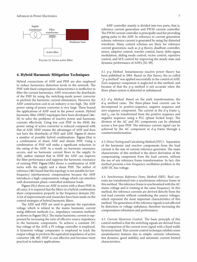
3.2. Series Active Filters. The main circuit configuration forthis type of AHF is shown in Figure 12. The idea here isto eliminate voltage harmonic distortions and improve thequality of the voltage applied to the load. This is achievedby producing a sinusoidal pulse width modulated (PWM)voltage waveform across the connection transformer, which
+7.5deg
−7.5deg 𝑉𝑑
𝐼𝑑
𝐼𝑑/2
𝐼𝑑/2
Figure 10: 24-pulse rectifier connection.
Supplytransformer
Active filter
Nonlinear load
PCC
Figure 11: Parallel active filter.
is added to the supply voltage to counter the distortionacross the supply impedance and present a sinusoidal voltageacross the load. Series AHF has to carry the full load currentincreasing their current ratings and 𝐼2𝑅 losses comparedwithparallel filters, especially across the secondary side of thecoupling transformer [43].
Unlike the shunt AHF, the series AHF is controlled on thebasis of the following methods:
(i) the controller detects the instantaneous supply cur-rent 𝑖𝑆,
(ii) the AHF extracts the harmonic current 𝑖𝑆from the
detected supply current by means of digital signalprocessing,
(iii) the active filter applies the compensating voltage𝑣𝐴𝐹(= −𝐾𝑖
𝑆ℎ) across the primary of the transformer.
This will result in a significant reduction in the supplyharmonic current (𝑖
𝑆ℎ), when the feedback gain 𝐾 is
set to be high enough [45].
An AHF with both series and parallel (shunt) connectedsections, as shown in Figures 11 and 12, respectively, can beused to compensate for both voltage and current harmonicssimultaneously [34–36]. In all cases, the critical requirementof any AHF circuit is to calculate the required compensationcurrent accurately and in real time.
Advances in Power Electronics 7
Supplytransformer
Active filter
Nonlinear load
Filtertransformer
Figure 12: Series active filter.
4. Hybrid Harmonic Mitigation Techniques
Hybrid connections of AHF and PHF are also employedto reduce harmonics distortion levels in the network. ThePHF with fixed compensation characteristics is ineffective tofilter the current harmonics. AHF overcomes the drawbacksof the PHF by using the switching-mode power converterto perform the harmonic current elimination. However, theAHF construction cost in an industry is too high. The AHFpower rating of power converter is very large. These boundthe applications of AHF used in the power system. Hybridharmonic filter (HHF) topologies have been developed [46–51] to solve the problems of reactive power and harmoniccurrents effectively. Using low cost PHF in the HHF, thepower rating of active converter is reduced compared withthat of AHF. HHF retains the advantages of AHF and doesnot have the drawbacks of PHF and AHF. Figure 13 showsa number of possible hybrid combinations. Figure 13(a) isa combination of shunt AHF and shunts PHF. Using acombination of PHF will make a significant reduction inthe rating of the AHF. As a result, no harmonic resonanceoccurs, and no harmonic current flows in the supply. In[50], author claimed that in HHF the AHF can improvethe filter performance and suppress the harmonic resonanceof existing PHF. Figure 13(b) shows a combination of AHFseries with the supply and a shunt PHF. The author ofreference [46] found that this topology is not suitable for low-frequency interharmonic compensation because the AHFintroduces a high compensation voltage which can interferewith downstream phase-controlled nonlinear loads.
Figure 13(c) shows an AHF in series with a shunt PHF. Inall cases, it is required that the filters in a hybrid combinationshare compensation properly in the frequency domain [51].A lot of improvements and researches have beenmade on thecontrol strategies of hybrid harmonic filters.
The AHF and PHF are used to generate the equivalentvoltage which is related to the mains harmonic currentusing different methods (i.e., impedance variation method)as shown in Figure 13(c).Themains harmonic current is sup-pressed by increasing the ratio of effective source impedanceto the harmonic components. To achieve a constant DCbus voltage of the AHF, a PI voltage controller is employed.A hysteresis voltage comparator is employed to track theoutput voltage to perform the equivalent impedance of activeconverter [48, 49]. HHF is cost effective and becomes morepractical in industry applications.
AHF controller mainly is divided into two parts, that is,reference current generation and PWM current controller.The PWMcurrent controller is principally used for providinggating pulse to the AHF. In reference to current generationscheme, reference current is generated by using the distortedwaveform. Many control schemes are there for referencecurrent generation, such as 𝑝-𝑞 theory, deadbeat controller,neuro, adaptive control, wavelet control, fuzzy, delta-sigmamodulation, sliding mode control, vector control, repetitivecontrol, and SFX control for improving the steady state anddynamic performance of AHFs [52–59].
4.1. p-q Method. Instantaneous reactive power theory hasbeen published in 1984. Based on this theory, the so-called“𝑝-𝑞method” was applied successfully in the control of AHF.Zero-sequence component is neglected in this method, andbecause of that the 𝑝-𝑞 method is not accurate when thethree-phase system is distorted or unbalanced.
4.2. d-q Method. Based on the park transformation, the𝑑-𝑞 method came. The three-phase load current can bedecomposed in positive-sequence, negative sequence andzero-sequence component. The current in the 𝑑-𝑞 frame 𝑖
𝑑
and 𝑖𝑞can be transformed from the positive sequence and
negative sequence using a PLL (phase locked loop). Thedivision of the AC and DC components can be obtainedacross a low-pass PHF. The reference current signal can beachieved by the AC component in 𝑑-𝑞 frame through acountertransformation.
4.3. Direct Testing andCalculatingMethod (DTC). Separationof the harmonic and reactive components from the loadcurrent is the aim of current reference generator. The maincharacteristic of this method is the direct derivation of thecompensating component from the load current, withoutthe use of any reference frame transformation. In fact, thismethod presents a low-frequency oscillation problem in theAHF DC bus voltage.
4.4. Synchronous Reference Fame Method (SRF). Real cur-rents are transformed into a synchronous reference frame inthismethod.The reference frame is synchronizedwith theACmains voltage and is rotating at the same frequency. In thismethod, the reference currents are derived directly from thereal load currents without considering the source voltages,which represent the most important characteristics of thismethod.The generation of the reference signals is not affectedby distortion or voltage unbalance, therefore increasing thecompensation robustness and performance.
4.5. Current Hysteresis Control. The basic principle of thiscontrol method is that the switching signals are derived fromthe comparison of the current error signal with a fixed widthhysteresis band.This current control technique exhibits someunsatisfactory features due to simple, extreme robustness,fast dynamic, good stability, and automatic current limitedcharacteristics.

8 Advances in Power Electronics
System
Shunt AHFAHF
𝑇1
𝑇2
𝑇3
𝑇4
(a)
System𝑇1
𝑇2
𝑇3
𝑇4
Filtertransformer
Shunt PHFSeries AHF
Activefilter
(b)
System𝑇1
𝑇2
𝑇3
𝑇4Ac
tive fi
lter Filter
transformer
Shunt PHF
Serie
s AH
F
(c)
Figure 13: Hybrid connections of active and passive filters.
4.6. Triangle-Comparison PWM Control. This control meth-od is also called linear current control. The conventionaltriangle-comparison PWM control principle is that the mod-ulation signal achieved by a current regulator from the cur-rent error signal is intersected with the triangle wave. Afterthat, pulse signals obtained are to control the switches of theconverters. With analog PWM circuit, this control methodhas simple implementation with fast speed of response.Because the modulation frequency equals the triangle fre-quency, the current loop gain crossover frequency must bekept below the modulation frequency.
4.7. Space Vector Modulation (SVM). The aim of this methodis to find the appropriate switching combinations and theirduty ratios according to certain modulation scheme. TheSVM operates in a complex plane divided in the six sectorsseparated by a combination of conducting or nonconductingswitches in the power circuit. The reference vector is used tolocate two adjacent switching-state vectors and compute thetime for which each one is active. SVM is of low speed ofresponse caused by the inherent calculation delay, due to thestrong antijamming and the good reliability of digital controltechnique. In order to solve the drawback, the improvementof adopting deadbeat control and a certain oversize of thesystem reactive components is advised.
Currently, the research trends of the AHF control strate-gies are mainly towards the optimizing and practical appli-cation of the control strategies. At the end, the comparativecriteria for PHF, AHF, and HHF could be summarized basedon the following:
(i) cost of the equipment and installation,(ii) harmonic indices (ex. 𝑖
ℎ, THD
𝑖, THD
𝑣, TDD, and
PWHD),(iii) life time and failure rate,(iv) maintenance and engineering.
5. Conclusions
Electrical system reliability and normal operation of electricalequipment rely heavily upon a clean distortion free powersupply. Designers and engineers wishing to reduce the level ofharmonic pollution on a power distribution network wherenonlinear harmonic generating loads are connected haveseveral harmonic mitigation techniques available. Becauseof the number and variety of available methods, selectionof the best-suited technique for a particular application isnot always an easy or straightforward process. A broadcategorization of different harmonic mitigation techniques(passive, active, and hybrid) has been carried out to give ageneral viewpoint on this wide-ranging and rapidly devel-oping topic. PHF is traditionally used to absorb harmoniccurrents because of low cost and simple robust structure.However, they provide fixed compensation and create sys-tem resonance. AHF provides multiple functions such asharmonic reduction, isolation, damping and termination,load balancing, PF correction, and voltage regulation. TheHHF is more attractive in harmonic filtering than the purefilters from both viability and economical points of view,particularly for high-power applications. It is hoped thatthe discussion and classification of harmonic mitigation

Advances in Power Electronics 9
techniques presented in this paper will provide some usefulinformation to help make the selection of an appropriateharmonic reduction method for a given application on aneasier task.
References
[1] A.Mansoor,W.M. Grady, A. H. Chowdhury, andM. J. Samotyi,“An investigation of harmonics attenuation and diversity amongdistributed single-phase power electronic loads,” IEEE Transac-tions on Power Delivery, vol. 10, no. 1, pp. 467–473, 1995.
[2] A. Mansoor, W. M. Grady, R. S. Thallam, M. T. Doyle, S. D.Krein, andM. J. Samotyj, “Effect of supply voltage harmonics onthe input current of single-phase diode bridge rectifier loads,”IEEE Transactions on Power Delivery, vol. 10, no. 3, pp. 1416–1422, 1995.
[3] G. Carpinelli, F. Iacovone, P. Varilone, and P. Verde, “Sin-gle phase voltage source converters: analytical modelling forharmonic analysis in continuous and discontinuous currentconditions,” International Journal of Power and Energy Systems,vol. 23, no. 1, pp. 37–48, 2003.
[4] E. F. El-Saadany and M. M. A. Salama, “Reduction of the netharmonic current produced by single-phase non-linear loadsdue to attenuation and diversity effects,” International Journalof Electrical Power and Energy Systems, vol. 20, no. 4, pp. 259–268, 1998.
[5] T. Key and J. S. Lai, “Analysis of harmonic mitigation methodsfor building wiring systems,” IEEE Transactions on PowerSystems, vol. 13, no. 3, pp. 890–897, 1998.
[6] M. H. Rashid and A. I. Maswood, “A novel method of harmonicassessment generated by three-phase AC-DC converters underunbalanced supply conditions,” IEEE Transactions on IndustryApplications, vol. 24, no. 4, pp. 590–597, 1988.
[7] R. E. Owen,M. F. McGranghan, and J. R. Vivirito, “Distributionsystem harmonics: controls for large power converters,” IEEETransactions on Power Apparatus and Systems, vol. 101, no. 3,pp. 644–652, 1982.
[8] T.Hoevenaars, K. LeDoux, andM.Colosino, “Interpreting IEEESTD 519 and meeting its harmonic limits in VFD applications,”in Proceedings of the 50th Annual Technical Conference ofthe Petroleum and Chemical Industry Committee, pp. 145–150,Houston, Tex, USA, September 2003.
[9] B. Singh, B. N. Singh, A. Chandra, K. Al-Haddad, A. Pandey,and D. P. Kothari, “A review of three-phase improved powerquality AC-DC converters,” IEEE Transactions on IndustrialElectronics, vol. 51, no. 3, pp. 641–660, 2004.
[10] “Investigation into execution of harmonic guidelines for house-hold and office electric applications,” Japanese IEE of JapanSC77A Domestic Committee Report, 2002.
[11] R. L. Smith and R. P. Stratford, “Power system harmonics effectsfrom adjustable-speed drives,” IEEE Transactions on IndustryApplications, vol. 20, no. 4, pp. 973–977, 1984.
[12] J. C. Das, Power System Analysis, Short-Circuit Load Flow andHarmonics, Marcel Dekker, New York, NY, USA, 2002.
[13] D. Alexa, A. Sırbu, and D. M. Dobrea, “An analysis of three-phase rectifiers with near-sinusoidal input currents,” IEEETransactions on Industrial Electronics, vol. 51, no. 4, pp. 884–891,2004.
[14] E. B. Makram, E. V. Subramaniam, A. A. Girgis, and R. Catoe,“Harmonic filter design using actual recorded data,” IEEETransactions on Industry Applications, vol. 29, no. 6, pp. 1176–1183, 1993.
[15] T. S. Key and J. S. Lai, “Comparison of standards and powersupply design options for limiting harmonic distortion in powersystems,” IEEETransactions on IndustryApplications, vol. 29, no.4, pp. 688–695, 1993.
[16] A. R. Prasad, P. D. Ziogas, and S. Manias, “A novel passivewaveshaping method for single-phase diode rectifiers,” IEEETransactions on Industrial Electronics, vol. 37, no. 6, pp. 521–530,1990.
[17] J. Yanchao and F.Wang, “Single-phase diode rectifier with novelpassive filter,” IEE Proceeding Circuits Devices Systems, vol. 145,no. 4, pp. 254–259, 1998.
[18] K. Hirachi, T. Iwade, and K. Shibayama, “Improvement of con-trol strategy on a step-down type high power factor converter,”National Conversion Record of Industrial Electronic EngineeringJapan, pp. 4.70–4.71, 1995.
[19] R. Ltoh, K. Lshizaka, H. Oishi, and H. Okada, “Single-phasebuck rectifier employing voltage reversal circuit for sinusoidalinput current waveshaping,” IEE Proceedings: Electric PowerApplications, vol. 146, no. 6, pp. 707–712, 1999.
[20] C. A. Canesin and I. Barbi, “A novel single-phase ZCS-PWMhigh-power-factor boost rectifier,” IEEE Transactions on PowerElectronics, vol. 14, no. 4, pp. 629–635, 1999.
[21] P. J. A. Ling and C. J. Eldridge, “Designing modern electricalsystems with transformers that inherently reduce harmonicdistortion in a PC-rich environment,” in Proceedings of thePower Quality Conference, pp. 166–178, 1994.
[22] J. C. Read, “The calculation of rectifier and inverter perfor-mance characteristics,” Journal of the Institute of ElectricalEngineers, vol. 92, no. 2, pp. 495–509, 1945.
[23] E. J. Cham and T. R. Specht, “The ANSI 49 rectifier with phaseshift,” IEEE Transactions on Industry Applications, vol. 20, no. 3,pp. 615–624, 1984.
[24] R. Hammond, L. Johnson, A. Shimp, and D. Harder, “Magneticsolutions to line current harmonic reduction,” in Proceedings ofthe Europe by International PowerConversionConference (PCIM’94), pp. 354–364, San Diego, Calif, USA, 1994.
[25] S. Kim, P.N. Enjeti, P. Packebush, and I. J. Pitel, “A new approachto improve power factor and reduce harmonics in a three-phase diode rectifier type utility interface,” IEEE Transactionson Industry Applications, vol. 30, no. 6, pp. 1557–1564, 1994.
[26] S. Choi, P. N. Enjeti, and I. J. Pitel, “Polyphase transformerarrangements with reduced kVA capacities for harmonic cur-rent reduction in rectifier-type utility interface,” IEEE Transac-tions on Power Electronics, vol. 11, no. 5, pp. 680–690, 1996.
[27] B.M. Bird, J. F.Marsh, and P. R.McLellan, “Harmonic reductionin multiplex converters by triple-frequency current injection,”Proceedings of the Institution of Electrical Engineers, vol. 116, no.10, pp. 1730–1734, 1969.
[28] Y. S. Tzeny, “Harmonic analysis of parallel-connected 12-pulseuncontrolled rectifier without an interphase transformer,” IEEProceeding Electrical Power Applications, vol. 145, no. 3, pp. 253–260, 1998.
[29] M. Hink Karl, “18 -Pulse Drives and Voltage Unbalance,”http://mtecorp.com/18pulse.html.
[30] T. H. Chen and M. Y. Huang, “Network modelling of 24-pulserectifier transformers for rigorous simulation of rail transitpower systems,” Electric Power Systems Research, vol. 50, no. 1,pp. 23–33, 1999.
[31] E. F. El-Saadany, R. Elshatshat, M. M. A. Salama, M. Kazerani,and A. Y. Chikhani, “Reactance one-port compensator and
10 Advances in Power Electronics
modular active filter for voltage and current harmonic reduc-tion in nonlinear distribution systems: a comparative study,”Electric Power Systems Research, vol. 52, no. 3, pp. 197–209, 1999.
[32] J. R. Johnson, “Proper use of active harmonic filters to benefitpulp and paper mills,” IEEE Transactions on Industry Applica-tions, vol. 38, no. 3, pp. 719–725, 2002.
[33] D. Li, Q. Chen, Z. Jia, and J. Ke, “A novel active power filter withfundamental magnetic flux compensation,” IEEE Transactionson Power Delivery, vol. 19, no. 2, pp. 799–805, 2004.
[34] W.M. Grady, M. J. Samotyi, and A. H. Noyola, “Survey of activeline conditioning methodologies,” IEEE Transactions on PowerDelivery, vol. 5, no. 3, pp. 1536–1541, 1990.
[35] M. Takeda, K. Ikeda, and Y. Tominaga, “Harmonic currentcompensation with active filter,” in Proceedings of the IEEE/IASAnnual Meeting, pp. 808–815, 1987.
[36] Z. Du, L. M. Tolbert, and J. N. Chiasson, “Active harmonicelimination for multilevel converters,” IEEE Transactions onPower Electronics, vol. 21, no. 2, pp. 459–469, 2006.
[37] S. Bhattacharya, T. M. Frank, D. M. Divan, and B. Banerjee,“Active filter system implementation,” IEEE Industry Applica-tions Magazine, vol. 4, no. 5, pp. 47–63, 1998.
[38] I. Takahashi, S. G. Li, and Y. Omura, “Low price and high poweractive filter,” in Proceedings of the IEEE/IAS Annual Meeting, pp.95–98, 1991.
[39] G. W. Chang and T. C. Shee, “A novel reference compensationcurrent strategy for shunt active power filter control,” IEEETransactions on Power Delivery, vol. 19, no. 4, pp. 1751–1758,2004.
[40] H. Akagi, “Control strategy and site selection of a shuntactive filter for damping of harmonic propagation in powerdistribution systems,” IEEE Transactions on Power Delivery, vol.12, no. 1, pp. 354–362, 1997.
[41] A. Cavallini and G. C. Montanari, “Compensation strategiesfor shunt active-filter control,” IEEE Transactions on PowerElectronics, vol. 9, no. 6, pp. 587–593, 1994.
[42] H. Akagi, H. Fujita, and K.Wada, “A shunt active filter based onvoltage detection for harmonic termination of a radial powerdistribution line,” IEEE Transactions on Industry Applications,vol. 35, no. 3, pp. 638–645, 1999.
[43] H. Fujita and H. Akagi, “A practical approach to harmoniccompensation in power systems—series connection of passiveand active filters,” IEEE Transactions on Industry Applications,vol. 27, no. 6, pp. 1020–1025, 1991.
[44] F. Z. Peng, H. Akagi, and A. Nabae, “A new approach toharmonic compensation in power systems—a combined systemof shunt passive and series active filters,” IEEE Transactions onIndustry Applications, vol. 26, no. 6, pp. 983–990, 1990.
[45] H. Akagi, “Active harmonic filters,” Proceedings of the IEEE, vol.93, no. 12, pp. 2128–2141, 2005.
[46] D. Basic, V. S. Ramsden, and P. K. Muttik, “Hybrid filtercontrol system with adaptive filters for selective elimination ofharmonics and interharmonics,” IEE Proceedings: Electric PowerApplications, vol. 147, no. 4, pp. 295–303, 2000.
[47] S. Senini and P. J. Wolfs, “Hybrid active filter for harmonicallyunbalanced three phase three wire railway traction loads,” IEEETransactions on Power Electronics, vol. 15, no. 4, pp. 702–710,2000.
[48] P. Salmeron, J. C. Montano, J. R. Vazquez, J. Prieto, and A.Perez, “Compensation in nonsinusoidal, unbalanced three-phase four-wire systems with active power-line conditioner,”IEEE Transactions on Power Delivery, vol. 19, no. 4, pp. 1968–1974, 2004.
[49] H. Akagi, “New trends in active filters for power conditioning,”IEEE Transactions on Industry Applications, vol. 32, no. 6, pp.1312–1322, 1996.
[50] H. L. Jou, J. C. Wu, and K. D. Wu, “Parallel operation of passivepower filter and hybrid power filter for harmonic suppression,”IEE Proceedings: Generation, Transmission andDistribution, vol.148, no. 1, pp. 8–14, 2001.
[51] X. Zha and Y. Chen, “The iterative learning control strategy forhybrid active filter to dampen harmonic resonance in industrialpower system,” in Proceedings of the IEEE International Sympo-sium on Industrial Electronics, vol. 2, pp. 848–853, 2003.
[52] B. Singh, K. Al-Haddad, and A. Chandra, “A review of activefilters for power quality improvement,” IEEE Transactions onIndustrial Electronics, vol. 46, no. 5, pp. 960–971, 1999.
[53] B. R. Lin, B. R. Yang, and H. R. Tsai, “Analysis and operationof hybrid active filter for harmonic elimination,” Electric PowerSystems Research, vol. 62, no. 3, pp. 191–200, 2002.
[54] D. Chen and S. Xie, “Review of the control strategies appliedto active power filters,” in Proceedings of the IEEE InternationalConference on Electric Utility Deregulation, Restructuring andPower Technologies (DRPT ’04), pp. 666–670, April 2004.
[55] K. Zhou, Z. Lv, A. Luo, and L. Liu, “Control strategy of shunthybrid active power filter in distribution network containingdistributed power,” in Proceedings of the China InternationalConference on Electricity Distribution (CICED ’10), pp. 1–10,September 2010.
[56] D. Detjen, J. Jacobs, R. W. De Doncker, and H. G. Mall, “A newhybrid filter to dampen resonances and compensate harmoniccurrents in industrial power systems with power factor correc-tion equipment,” IEEE Transactions on Power Electronics, vol.16, no. 6, pp. 821–827, 2001.
[57] M. Aredes, J. Hafner, and K. Heumann, “Three-phase four-wire shunt active filter control strategies,” IEEE Transactions onPower Electronics, vol. 12, no. 2, pp. 311–318, 1997.
[58] M. Aredes, L. F. C. Monteiro, and J. M. Miguel, “Controlstrategies for series and shunt active filters,” in Proceedings ofthe IEEE Bologna Power Tech Conference, pp. 1–6, June 2003.
[59] S. Khalid and A. Triapthi, “comparison of sinusoidal currentcontrol strategy & synchronous rotating frame strategy for totalharmonic reduction for power electronic converters in aircraftsystem under different load conditions,” International Journal ofAdvanced Research in Electrical, Electronics and InstrumentationEngineering, vol. 1, no. 4, pp. 305–313, 2012.

International Journal of
AerospaceEngineeringHindawi Publishing Corporationhttp://www.hindawi.com Volume 2014
RoboticsJournal of
Hindawi Publishing Corporationhttp://www.hindawi.com Volume 2014
Hindawi Publishing Corporationhttp://www.hindawi.com Volume 2014
Active and Passive Electronic Components
Control Scienceand Engineering
Journal of
Hindawi Publishing Corporationhttp://www.hindawi.com Volume 2014
International Journal of
RotatingMachinery
Hindawi Publishing Corporationhttp://www.hindawi.com Volume 2014
Hindawi Publishing Corporation http://www.hindawi.com
Journal ofEngineeringVolume 2014
Submit your manuscripts athttp://www.hindawi.com
VLSI Design
Hindawi Publishing Corporationhttp://www.hindawi.com Volume 2014
Hindawi Publishing Corporationhttp://www.hindawi.com Volume 2014
Shock and Vibration
Hindawi Publishing Corporationhttp://www.hindawi.com Volume 2014
Civil EngineeringAdvances in
Acoustics and VibrationAdvances in
Hindawi Publishing Corporationhttp://www.hindawi.com Volume 2014
Hindawi Publishing Corporationhttp://www.hindawi.com Volume 2014
Electrical and Computer Engineering
Journal of
Advances inOptoElectronics
Hindawi Publishing Corporation http://www.hindawi.com
Volume 2014
The Scientific World JournalHindawi Publishing Corporation http://www.hindawi.com Volume 2014
SensorsJournal of
Hindawi Publishing Corporationhttp://www.hindawi.com Volume 2014
Modelling & Simulation in EngineeringHindawi Publishing Corporation http://www.hindawi.com Volume 2014
Hindawi Publishing Corporationhttp://www.hindawi.com Volume 2014
Chemical EngineeringInternational Journal of Antennas and
Propagation
International Journal of
Hindawi Publishing Corporationhttp://www.hindawi.com Volume 2014
Hindawi Publishing Corporationhttp://www.hindawi.com Volume 2014
Navigation and Observation
International Journal of
Hindawi Publishing Corporationhttp://www.hindawi.com Volume 2014
DistributedSensor Networks
International Journal of