scalar diffraction - the prism awards for photonics ... · pdf filescalar diffraction from...
TRANSCRIPT
2 Diffraction Fundamentals
Scalar Diffraction
From experimental observations it is known that longerwavelengths are diffracted at larger angles, and that tighterfocal spots are obtained from larger-aperture lenses. Thishas led to the formulation of the fundamental relation fora diffraction angle θd being proportional to the wavelengthof light λ, and inversely proportional to the size D of thepropagating wave:
θd ∝ λ/D
Solutions to a diffraction problem consider the spatial evolutionof finite-sized waves and waves whose propagation wasdisrupted by amplitude or phase objects. Rigorous solutionsto diffraction problems satisfy Maxwell’s equations andthe appropriate boundary conditions. A simpler approach isbased on the Huygens-Fresnel principle, which defines thefoundation for scalar diffraction theory.
Scalar diffraction theory assumes that the propagating fieldcan be treated as a scalar field. The propagation of a fielddescribed by its complex amplitude U (x, y, z) in free spacefrom the object plane (z = 0) to the observation plane is governedby the Helmholtz equation:
∇2U (x, y, z)+k20U (x, y, z)= 0
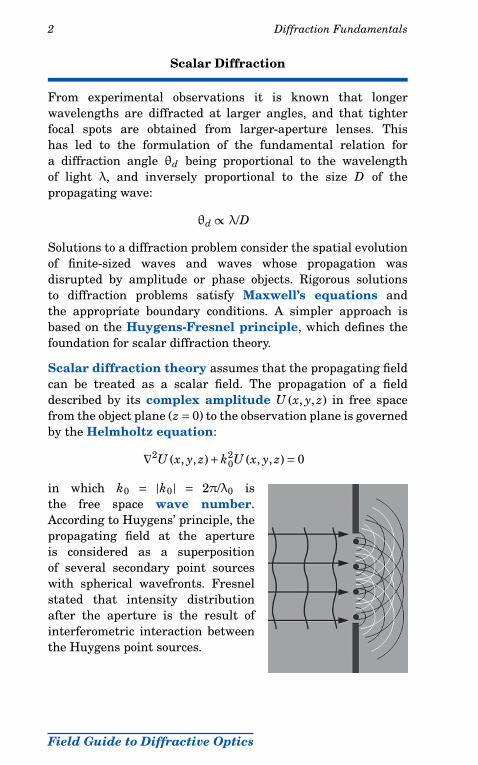
in which k0 = |k0| = 2π/λ0 isthe free space wave number.According to Huygens’ principle, thepropagating field at the apertureis considered as a superpositionof several secondary point sourceswith spherical wavefronts. Fresnelstated that intensity distributionafter the aperture is the result ofinterferometric interaction betweenthe Huygens point sources.
Field Guide to Diffractive Optics

6 Fresnel Diffraction
Fresnel Zone Plates
A Fresnel zone plate (FZP) represents an amplitude maskthat consists of alternating opaque and transparent rings. Eachring size corresponds to a Fresnel zone as defined by theobservation point. FZPs are often employed in lieu of lenses toconcentrate the propagating field into a tight on-axis spot.
Increasing the number of zones progressively reduces the width,as well as increases the peak intensity and the total powercontained in the central peak of the diffraction pattern.
Field Guide to Diffractive Optics
26 Diffraction by Multiple Apertures
Aperture Fill Factor
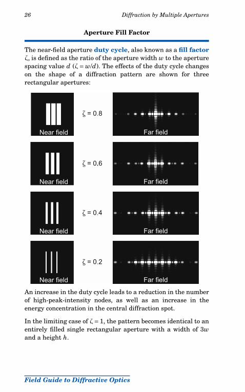
The near-field aperture duty cycle, also known as a fill factorζ, is defined as the ratio of the aperture width w to the aperturespacing value d (ζ= w/d). The effects of the duty cycle changeson the shape of a diffraction pattern are shown for threerectangular apertures:
An increase in the duty cycle leads to a reduction in the numberof high-peak-intensity nodes, as well as an increase in theenergy concentration in the central diffraction spot.
In the limiting case of ζ= 1, the pattern becomes identical to anentirely filled single rectangular aperture with a width of 3wand a height h.
Field Guide to Diffractive Optics

36 Diffractive Components
Diffraction Gratings
Diffraction gratings are periodic diffractive structures thatmodify the amplitude or phase of a propagating field. Lineargratings represent the simplest periodic diffractive structures.
Amplitude gratings are based on the amplitude modulationof the incident wavefront and are employed in spectral regionswhere nonabsorbing optical materials are not available. Theamplitude modulation is associated with transmission lossesintroduced by the grating.
Phase gratings are based on the phase modulation of theincident wavefront by introducing a periodic phase delay tothe individual portions of the propagating wavefront. Phasegratings are designed to work in transmission, reflection, orin a bidirectional manner.
Surface-relief phase gratings are based on wavefront-divisioninterference principles and introduce periodic phase delays tothe fractions of the incident wavefront due to periodic changesof the substrate thickness.
triangular profilephase grating with
Reflective surface-relief
with triangular profilerelief phase gratingTransmissive surface-
Reflective surface-relief phase grating withsinusoidal profile
Field Guide to Diffractive Optics