shelter 1 : structural assessment – indonesia, padang · shelter 1 : structural assessment ......
TRANSCRIPT

Subject IFRC – Transitional Shelter
Date 26
th April 2011
Y:\214933- IFRC TRANSITIONAL SHELTER BOOK\4-00 INTERNAL PROJECT DATA\4-05 REPORTS
Shelter 1: Structural Assessment
1.1 Introduction and Purpose
Arup was commissioned to carry out a structural review to assess and validate nine selected shelter designs for the IFRC. This document summarises the information gathered for and the key outcomes of the verification of the strCross. This assessment is based on the input documents listed in Appendix A.
Summary Information:
Disaster: Earthquake, 2009
Materials: Timber frame, palm fibrepanels
Materials source: Local
Time to build: 2 days
Anticipated lifespan: 6-12 months (residents expected it to last
Construction team: 5 people
Number built: 7000
Approximate materials cost per shelter:
Approximate programme cost per shelter:
Shelter Description:
The shelter is a timber framed structure with palm roofing and walls. It measures
and is 3.35m tall to the ridge beam and 2.4m to the eaves with a pitched roof of 23.6 degrees.
The stability is provided by three portal fra
eaves and ridge level. Each portal frame is made up of
rafters and bracing members. The haunch bracing in the frames provides lateral stiffness.
non-structural members include: flo
support palm matting wall panels depending on the material used. The shelter has a suspended
floor, assumed to be coconut wood boarding spanning between the floor joists. The columns are
embedded into concrete bucket foundations that sit directly on the ground.
The timber is untreated but will have some resistance to termite attack since the shfrom the ground. The palm roof and walls will require replacement if damaged by the wexpected life of the structure is exceeded. lifespan of the untreated materials mean that it is unlikely they will be reusedexception of the doors.
Transitional Shelter Job No/Ref 214933/ER
05 REPORTS\SHELTER 1- SUMATRA\26-04-2011 REVISED ISSUE\S1 INDONESIA PADANG
: Structural Assessment – Indonesia, Padang
and Purpose
Arup was commissioned to carry out a structural review to assess and validate nine selected shelter the IFRC. This document summarises the information gathered for and the key
outcomes of the verification of the structural performance of Shelter 1, built by the Indonesian ReThis assessment is based on the input documents listed in Appendix A.
fibre roof, concrete bucket foundations and palm matting wall
(residents expected it to last more than 24 months)
als cost per shelter: 350 CHF (2009)
Approximate programme cost per shelter: 500 CHF (2009)
a timber framed structure with palm roofing and walls. It measures 4.5m x 4m on plan
and is 3.35m tall to the ridge beam and 2.4m to the eaves with a pitched roof of 23.6 degrees.
three portal frames tied together by horizontal members at ground,
. Each portal frame is made up of two or three columns and a roof truss wi
. The haunch bracing in the frames provides lateral stiffness.
structural members include: floor joists, roof joists spanning between rafters and transoms to
support palm matting wall panels depending on the material used. The shelter has a suspended
floor, assumed to be coconut wood boarding spanning between the floor joists. The columns are
ded into concrete bucket foundations that sit directly on the ground.
The timber is untreated but will have some resistance to termite attack since the shelter is raised from the ground. The palm roof and walls will require replacement if damaged by the wexpected life of the structure is exceeded. The shelter is intended to be demountable but the short lifespan of the untreated materials mean that it is unlikely they will be reused, with the
214933/ER
Page 1 of 18
Indonesia, Padang
Arup was commissioned to carry out a structural review to assess and validate nine selected shelter the IFRC. This document summarises the information gathered for and the key
Indonesian Red
, concrete bucket foundations and palm matting wall
months)
4.5m x 4m on plan
and is 3.35m tall to the ridge beam and 2.4m to the eaves with a pitched roof of 23.6 degrees.
tal members at ground,
two or three columns and a roof truss with
. The haunch bracing in the frames provides lateral stiffness. Secondary
or joists, roof joists spanning between rafters and transoms to
support palm matting wall panels depending on the material used. The shelter has a suspended
floor, assumed to be coconut wood boarding spanning between the floor joists. The columns are
elter is raised from the ground. The palm roof and walls will require replacement if damaged by the wind or if the
The shelter is intended to be demountable but the short with the possible

Y:\214933- IFRC TRANSITIONAL SHELTER BOOK\4-00 INTERNAL PROJECT DATA\4-05 REPORTS\SHELTER 1- SUMATRA\26-04-2011 REVISED ISSUE\S1 INDONESIA PADANG
STRUCTURAL ASSESSMENT_01.DOCX
© Arup | F0.13 | July 2010
1.2 Location and Geo-hazards
1.2.1 Location of Shelter
West Sumatra, Indonesia
Areas and districts of Padang, including: Kota Padang, Kota Pariaman and Padang Pariaman. It has therefore been assumed that all of the shelters are situated on flat land in coastal locations. An approximate latitude and longitude for the site are: 0 deg 57’ S, 100deg 21’ E.
1.2.2 Hazards
A summary of the natural hazards faced in Sumatra are given below1:
• HIGH Earthquake Risk. A map from the Indonesian Design Code2 suggests that the shelters
are in an area with a high peak ground acceleration (PGA) of 0.3g for an earthquake return period of 500 years
3.
• LOW Wind Loading. Not prone to tropical storms or cyclones. Details of assumptions made for wind loading are given in Section 1.8.3.
• HIGH Flood Risk. High rainfall and high run-off may lead to flash floods. The area is also prone to storms and lightning strikes.
• HIGH landslide risk due to earthquakes or flooding if shelters are located near potentially unstable slopes.
• Other hazards that will not be designed against include potentially active volcanoes, tsunami, and potentially high wildfire risk depending on exact location.
• Tropical climate with consistent temperatures around 28 degrees average. High humidity and monsoons.
1 ‘Natural Hazards in Aceh’, Yasir Khokher and Ziggy Lubkowski, November 2009 (refer to Appendix C).
2 ‘2003-07 SNI 2003-1726-2003’
3 This is conservative since a 475 year return period has generally been used with the code.

Y:\214933- IFRC TRANSITIONAL SHELTER BOOK\4-00 INTERNAL PROJECT DATA\4-05 REPORTS\SHELTER 1- SUMATRA\26-04-2011 REVISED ISSUE\S1 INDONESIA PADANG
1.3 Geometry
The geometry was determined using the drawings and photographic information provided, see Figure 1 for key members and levels. A GSA model detailing the geometry has been created from this data as illustrated in Figure 2.
Figure 1.1 – Sketch of Geometry
The shelter is 4.5m x 4m on plan and is 3.35m tall to the ridge beam and 2.4m to the eaves. It has a pitched roof of 23.6 degrees. The structure consists of three portal frames joined by horizontal members. Each portal frame is made up of two or three columns and a roof truss with rafters and bracing members.
Figure 1.2 – GSA Model
The portal frames are also tied together at ground and ridge level. Secondary non-structural members include: floor joists, roof joists spanning between rafters and transoms or mullions to support wall panels depending on the material used. The shelter has a suspended floor, assumed to be coconut wood boarding spanning between the floor joists. The columns are embedded into concrete bucket foundations that sit directly on the ground.
Transverse Longitudinal

Y:\214933- IFRC TRANSITIONAL SHELTER BOOK\4-00 INTERNAL PROJECT DATA\4-05 REPORTS\SHELTER 1- SUMATRA\26-04-2011 REVISED ISSUE\S1 INDONESIA PADANG
STRUCTURAL ASSESSMENT_01.DOCX
© Arup | F0.13 | July 2010
1.4 Structural System
• Vertical loads are taken by 8 columns supported on concrete bucket foundations.
• Global stability in the transverse direction is provided by three portal (moment) frames. These consist of two or three columns and a roof truss with bracing members at the haunches.
• Global stability in the longitudinal direction is provided by two moment frames at each side, with stiffened haunches.
Figure 1.3 – Deflected Shape of Lateral System
• There are single or double diagonal bracing members between portal frames in the longitudinal direction but these do not contribute to the structural system since there are no tie members between portal frames at eaves level.
• There is no bracing in the plane of the roof; therefore it cannot act as a diaphragm when palm thatch is used. Bracing or properly nailed roof sheets will be required to achieve diaphragm action.
• There is no code compliant lateral stability system in the shelter and the stability is dependent on the haunches of the portal frames.
1.5 Member Sizes
The table below shows the member sizes that have been assumed for the structural assessment. These sizes have been based on information given in the drawings and Bill of Quantities in Appendix A. The amended Bill of Quantities is given in Appendix B.
Name Length (m) Description Number
Structural Members
Beam 1 4.0 R(cm)10.x5. 6
Beam 2 4.5 R(cm)10.x5. 6
Columns 2.75 (3.65) R(cm)10.x5. 6 (2)
Portal Brace 0.65 R(cm)10.x5. 10
Truss Brace 0.78 (0.95) R(cm)7.x5. 6 (1)
Rafter 2.80 R(cm)7.x5. 6
Secondary Members
Beam 3 – Floor Joists 4.5 R(cm)10.x5. 7
Transom 2.25 (2) R(cm)7.x5. 4 (4)
Roof Joist 4.50 R(cm)7.x5. 4

Y:\214933- IFRC TRANSITIONAL SHELTER BOOK\4-00 INTERNAL PROJECT DATA\4-05 REPORTS\SHELTER 1- SUMATRA\26-04-2011 REVISED ISSUE\S1 INDONESIA PADANG
STRUCTURAL ASSESSMENT_01.DOCX
© Arup | F0.13 | July 2010
1.6 Materials
The building consists of a coconut wood frame, with palm thatching and woven palm matting walls. The foundations are concrete, cast in buckets. It has been assumed that the floor is boarded with coconut wood boards.
1.6.1 Material Assumptions
Type IFRC Specification Arup Assumption Comments
Concrete K175, 1:2:3 mix Compressive cube strength, fcu
= 15-20MPa (low strength
concrete).
References to a K175 mix have been found
in BRR1 documentation but this is not a
standard grade.
Palm
Thatch
Palm thatch/fibre roofing
underlain with polythene
sheet. Woven palm
matting walls.
A density of 20kg/m2 has been
assumed, and a similar fibrous
material for the walls.
Material is light weight and assumed to be
sacrificial under high wind loads.
Timber Coconut wood2 Medium to low density
coconut wood with a design
bending strength of 4-
15N/mm2, a density of
400kg/m3, and an elastic
modulus of 7584N/mm2.
Member dimensions given are assumed to
be as cut – no sacrificial allowance has been
made. The coconut wood used has very
variable material properties; therefore it is
recommended that the timber used has a
minimum bending strength of 15 N/mm2.
Nails No information provided. 8d nails (~4.1mm diameter) to
an embedment of 50mm. All
connections assumed to be
nailed with 2 nails.
Connections are assumed to be nailed with
the minimum number of nails to stabilise
the joints.
Bolts No information provided. Bolted connections assumed at
the haunches in combination
with notching of the adjoining
beams and columns.
Roof
upgrade
Zinc/iron sheeting for
roof upgrade
2.5m x 3m, 0.45mm thick,
corrugated iron sheets -
maximum span of 1.5m.
Wall
upgrade
Wooden board panelling
or masonry blocks
Plywood for wall upgrade will
be ½” thick structural grade,
24/16 span rated and 4 ply.
Framing must be spaced at 600mm and a
maximum nail spacing of 150mm used.
1 BRR, the Agency for the Rehabilitation and Reconstruction of Aceh and Nias, coordinated and jointly implemented
the recovery programme following the Aceh tsunami (2004) and the Nias earthquake (2005). 2 For more information about the properties of coconut wood see Section 1.6.2.

Y:\214933- IFRC TRANSITIONAL SHELTER BOOK\4-00 INTERNAL PROJECT DATA\4-05 REPORTS\SHELTER 1- SUMATRA\26-04-2011 REVISED ISSUE\S1 INDONESIA PADANG
STRUCTURAL ASSESSMENT_01.DOCX
© Arup | F0.13 | July 2010
1.6.2 Timber - Coconut Wood
Coconut wood is sawn cut from coconut palms which average 30-40cm diameter and can reach a height of 20-25m. In cross-section the tree has three areas; dermal (high density), sub-dermal (medium density) and core (low density). The density decreases with height and increases from the core to the cortex and can vary by as much as 800kg/m
3 in one palm. The moisture content also
increases with decreasing density and can be up to 400% at the top. It is recommended that only the high or medium density wood is used structurally with the low density wood being reserved for non-load bearing elements
1.
The durability of the wood is largely influenced by insects and is untreated; raising the structure on concrete provides termite protection. It should be noted that the performance is highly dependent on the quality of timber used, but that in general graded coconut wood shows a similar variation in properties to standard timber. The assumptions made for the timber are given in the table above.
1.7 Codes, Standards and References
General
The IBC (International Building Code) 2009 has been used as a basis for the design checks since it is widely accepted worldwide, particularly for extreme loading cases such as earthquakes or strong winds. Other codes have been referenced where appropriate or where the IBC is thought to be less applicable. This includes the Eurocodes and local codes where appropriate.
Other references used:
• Indonesian code (SNI 03-1726-2003)
• Standards referred to by IBC 2009 including: ASCE 7-10 (2010), NDS for Wood Construction, ACI 318 for Concrete, and AISC for Steel.
• UBC 1997 Volume 2 for preliminary wind calculations
• Asia Pacific Forestry Sector Outlook: Focus on Coconut Wood, RN Arancon, October 1997, for properties and information on coconut timber and properties.
1.8 Loads
1.8.1 Dead Loads
• Self-weight of structural materials, assuming medium/low density coconut wood (400kg/m3)
for timbers and floor boards.
1 ‘Asia Pacific Forestry Sector Outlook: Focus on Coconut Wood’, APFSOS/WP/23, R.N. Arancon, October 1997.
Y:\214933- IFRC TRANSITIONAL SHELTER BOOK\4-00 INTERNAL PROJECT DATA\4-05 REPORTS\SHELTER 1- SUMATRA\26-04-2011 REVISED ISSUE\S1 INDONESIA PADANG
STRUCTURAL ASSESSMENT_01.DOCX
© Arup | F0.13 | July 2010
1.8.2 Live Loads
• For IBC compliancy live loads of 1.92kN/m2 on the ground floor and 0.96kN/m
2 on the roof
should be applied1. In this case however, no live loads are assumed on the roof since there
will be no maintenance access and snow load so it is not applicable. The live load allowance for the ground floor has been reduced to 0.9kN/m
2 since this represents a more realistic
loading situation.
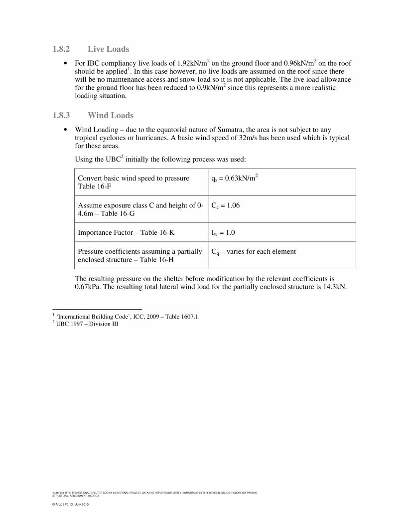
1.8.3 Wind Loads
• Wind Loading – due to the equatorial nature of Sumatra, the area is not subject to any tropical cyclones or hurricanes. A basic wind speed of 32m/s has been used which is typical for these areas.
Using the UBC2 initially the following process was used:
Convert basic wind speed to pressure Table 16-F
qs = 0.63kN/m2
Assume exposure class C and height of 0-4.6m – Table 16-G
Ce = 1.06
Importance Factor – Table 16-K Iw = 1.0
Pressure coefficients assuming a partially enclosed structure – Table 16-H
Cq – varies for each element
The resulting pressure on the shelter before modification by the relevant coefficients is 0.67kPa. The resulting total lateral wind load for the partially enclosed structure is 14.3kN.
1 ‘International Building Code’, ICC, 2009 – Table 1607.1. 2 UBC 1997 – Division III
Y:\214933- IFRC TRANSITIONAL SHELTER BOOK\4-00 INTERNAL PROJECT DATA\4-05 REPORTS\SHELTER 1- SUMATRA\26-04-2011 REVISED ISSUE\S1 INDONESIA PADANG
STRUCTURAL ASSESSMENT_01.DOCX
© Arup | F0.13 | July 2010
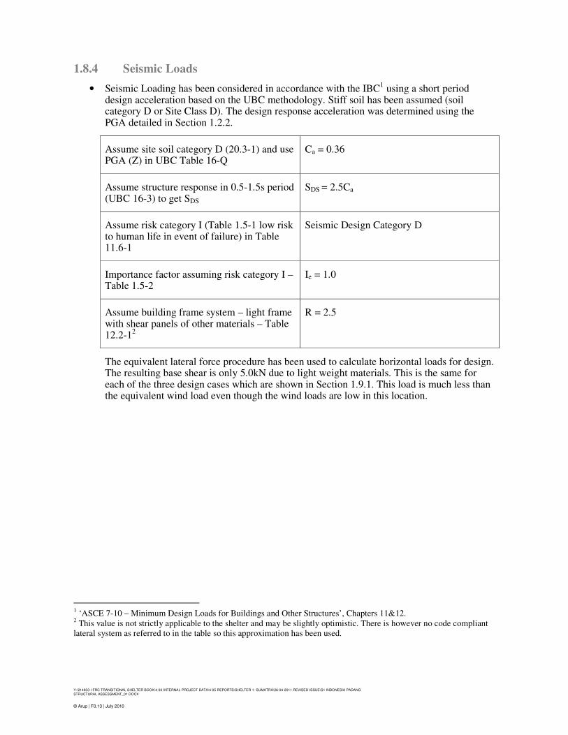
1.8.4 Seismic Loads
• Seismic Loading has been considered in accordance with the IBC1 using a short period
design acceleration based on the UBC methodology. Stiff soil has been assumed (soil category D or Site Class D). The design response acceleration was determined using the PGA detailed in Section 1.2.2.
Assume site soil category D (20.3-1) and use PGA (Z) in UBC Table 16-Q
Ca = 0.36
Assume structure response in 0.5-1.5s period (UBC 16-3) to get SDS
SDS = 2.5Ca
Assume risk category I (Table 1.5-1 low risk to human life in event of failure) in Table 11.6-1
Seismic Design Category D
Importance factor assuming risk category I – Table 1.5-2
Ie = 1.0
Assume building frame system – light frame with shear panels of other materials – Table 12.2-1
2
R = 2.5
The equivalent lateral force procedure has been used to calculate horizontal loads for design. The resulting base shear is only 5.0kN due to light weight materials. This is the same for each of the three design cases which are shown in Section 1.9.1. This load is much less than the equivalent wind load even though the wind loads are low in this location.
1 ‘ASCE 7-10 – Minimum Design Loads for Buildings and Other Structures’, Chapters 11&12.
2 This value is not strictly applicable to the shelter and may be slightly optimistic. There is however no code compliant
lateral system as referred to in the table so this approximation has been used.

Y:\214933- IFRC TRANSITIONAL SHELTER BOOK\4-00 INTERNAL PROJECT DATA\4-05 REPORTS\SHELTER 1- SUMATRA\26-04-2011 REVISED ISSUE\S1 INDONESIA PADANG
STRUCTURAL ASSESSMENT_01.DOCX
© Arup | F0.13 | July 2010
1.9 Calculation Plan
1.9.1 Design Methodology
The performance of each shelter has been assessed by checking that the structure as assumed from the information provided is safe for habitation. Relevant codes and standards have been used as the baseline for identifying appropriate performance/design criteria, but the shelter has not been checked for strict code compliance. Logical reasoning has therefore be used where necessary and upgrades suggested in order for the shelter to meet these criteria.
Three possible cases have been considered for the shelter.
CASE A: Skeletal frame (permeable or destructible walling/roofing). The structure will attract seismic loads (from its own self-weight) but is assumed to attract negligible wind loads.
CASE B: Upgraded to Canopy (as Case A but with metal sheets for roof). Seismic lateral loads will be considered and wind uplift on canopy will be considered.
CASE C: Upgraded to Enclosed (as Case B but also with nailed plywood walls). Seismic lateral loads will be considered and wind loads are expected to govern laterally and will act on both roof and walls. Note that the design of the walls has been modified from the original framing for Case C.
1.9.2 Structural Checks
For a summary of the checks performed to assess the building, refer to Appendix C.

Y:\214933- IFRC TRANSITIONAL SHELTER BOOK\4-00 INTERNAL PROJECT DATA\4-05 REPORTS\SHELTER 1- SUMATRA\26-04-2011 REVISED ISSUE\S1 INDONESIA PADANG
STRUCTURAL ASSESSMENT_01.DOCX
© Arup | F0.13 | July 2010
2 Results of Structural Assessment
2.1 General key findings
• The material specifications and type of fixings for Shelter 1 are not well defined. Arup has made reasonable assumptions but exact specifications will depend on which materials are available where the shelter is applied.
• The nature of the connections is uncertain and will have a significant effect on the performance of the shelter.
2.2 Seismic
2.2.1 Cases A, B and C
• Since the weight of the shelter is similar for all three cases the seismic loads are also similar. The structure is extremely light-weight and therefore attracts a very small horizontal seismic load.
• In Case A the roofing material is very light-weight, therefore if the roof is damaged or the house collapses, it will pose less of a risk to life safety for the occupants. For Cases B & C, the roof is still relatively lightweight and has similar benefits to the overall structural performance.
• For Cases B & C, portal frame action in both directions is used to resist horizontal loads; this relies on the stiffness of the connections which is uncertain. There is no bracing in the plane of the walls so there is little stiffness to resist lateral loads. Since the frame lacks stiffness, there are high displacements under earthquake loading. This will therefore lead to unpredictable behaviour and damage to the structure. Assuming the frames act as moment frames, the timber columns are overstressed in the seismic case. Alternately, for Cases A & B, bracing (timber or metal straps) could be provided to stiffen the structure.
• Case C, with nailed plywood walls, would be considered a code-compliant type of lateral system and would have considerably more stiffness.
• Larger foundations are required to withstand lateral seismic loads and alternative foundation solutions are required for Cases B & C.
• Taking all of this into account, damage is to be expected from earthquake loading for Cases A & B, but due to the light-weight it is not expected that there is a high risk to life safety. Case C, if properly detailed with modified wall framing, could perform well under the design earthquake and come close to meeting a code Life Safety performance.
• In general we do not recommend upgrading structures using masonry/cement blocks as this would increase the weight and therefore the seismic loads. Un-confined masonry panels are also vulnerable to collapse and pose a high risk to life safety.
2.3 Wind
2.3.1 Case A
• For case A the wind load on the frame is negligible due to the sacrificial nature of the roof and wall material.

Y:\214933- IFRC TRANSITIONAL SHELTER BOOK\4-00 INTERNAL PROJECT DATA\4-05 REPORTS\SHELTER 1- SUMATRA\26-04-2011 REVISED ISSUE\S1 INDONESIA PADANG
STRUCTURAL ASSESSMENT_01.DOCX
© Arup | F0.13 | July 2010
2.3.2 Cases B and C
• The shelter can be upgraded to case B by the use of corrugated iron or zinc sheeting fixed to the roof purlins or joists. In this case the roof will attract wind loads, but the walls are still considered skeletal.
• The wind loads result in foundation uplift for both Case B and C. In other words, the total dead load of the structure including the weight of the footing is much less than the vertical uplift demand caused by the wind case. However, it been assumed that the columns are simply cast into concrete footings without any continuous connection detail. It is therefore likely that the columns will pull out and not engage the foundations in the uplift condition, worsening the magnitude of net uplift on the foundations. A possible alternative foundation solution to prevent uplift would be the use of ground anchors as shown in Figure 2.1.
Figure 2.1 – Alternative Foundation Options
• In both case B and C overstress of the roof members will occur, including the purlins, roof truss bracing and rafters.
• The canopy can be further upgraded to Case C using nailed plywood sheets as the walls. We have assumed a closer spacing of vertical framing of 24” and nailed 24/16 4-ply plywood with maximum 6” on centre nail spacing.
• For Case C, this results in lateral wind pressures acting on the roof and walls. Both the in-plane and out of plane forces in the wall in this case are acceptable. A more substantial header beam will be required and potentially in-plane bracing in the roof to resist the out of plane wind pressures for Case C.
• High lateral deflections are expected for Case B and are greater than the usually acceptable limit of height of the building/400. For Case C, with the stiffer nailed plywood walls, deflections are expected to be more typical.
• The foundations would need to be more substantial in order to prevent sliding under wind lateral loads, and to prevent uplift which is greater than for Case B. The lateral connection of the columns to the foundations requires at least 100mm of embedment of the column into the concrete. In both cases the bearing pressures are acceptable.
2.4 Other Hazards
• Provisions against flooding have been provided in raising structure using foundations. This will also help to prevent against termite attack on the wooden members.

Y:\214933- IFRC TRANSITIONAL SHELTER BOOK\4-00 INTERNAL PROJECT DATA\4-05 REPORTS\SHELTER 1- SUMATRA\26-04-2011 REVISED ISSUE\S1 INDONESIA PADANG
STRUCTURAL ASSESSMENT_01.DOCX
© Arup | F0.13 | July 2010
2.5 Summary of Results
Conclusions Recommendations
Figure 3.1 – CASE A Skeletal Frame
• Light-weight with woven mat walls and palm fibre roof that are sacrificial
• Wind forces are insignificant
• Lateral stability provided by highly flexible portal frames leading to large deflections and damage to the frame
• Addition of roofing or initial asymmetry during building will cause lateral movement
• In plane bracing in walls is required to improve lateral stiffness and some member sizes need to increase
• The columns must be tied down to the bucket foundations and foundation sizes increased to resist seismic loads
Figure 3.2 – CASE B Canopy
• Basic shelter upgraded with iron roof sheets to a canopy structure
• Roofing results in higher uplift wind loads on the roof
• This results in uplift on the foundations
• Bracing required as for Case A
• Roof members strengthened and spacing decreased
• The columns must be tied down to the foundations and an alternative foundation solution such as ground anchors is required – see Section 2.3.2.
Figure 3.3 – CASE C Enclosed
• Further upgrade of the shelter walls using properly designed and detailed nailed plywood, increases the lateral stiffness
• Increased wall wind loads result in sliding of the foundations
• Bracing required as for Case A
• Additional posts introduced as part of the nailed plywood wall system and increase in size of header beam. The roof may also require in-plane bracing
• The columns must be tied down to the foundations and an alternative foundation solution such as ground anchors is required – see Section 2.3.2.

Y:\214933- IFRC TRANSITIONAL SHELTER BOOK\4-00 INTERNAL PROJECT DATA\4-05 REPORTS\SHELTER 1- SUMATRA\26-04-2011 REVISED ISSUE\S1 INDONESIA PADANG
STRUCTURAL ASSESSMENT_01.DOCX
© Arup | F0.13 | July 2010
3 Conclusions and Recommendations
3.1 Assumptions
1. The structure has been checked for a roofing material weight of 0.2kN/m2
and the maximum allowable floor live load is 0.9kN/m
2 which is appropriate for lightweight shelter design.
2. The palm matting and thatch has been assumed to be sacrificial or permeable under wind loading. Where walls and roof are upgraded care should be taken to modify the structure to resist the additional wind or seismic loads.
3. A stiff soil type (see Site Class D, ‘2009 International Building Code’, ICC, February 2009) has been assumed in analysis of the structure. Softer soil or soil of variable quality may adversely affect the performance of the shallow foundations in service. For sites where liquefaction may be a hazard (near river beds, coastal areas with sandy soils and high water tables), the shelters could be seriously damaged if soil liquefies in an earthquake but such damage is unlikely to pose a life safety risk to occupants due to the lightweight nature of the structure.
4. The design and detailing of all connections is critical to the stability of the structure and should be checked for local load cases, it has been assumed that all connections can transmit member forces.
3.2 Conclusions
Performance Analysis
Performance under gravity loads is satisfactory. However the walls require bracing to provide lateral stability and columns must be tied to foundations.
Hazard Performance
Earthquake – HIGH Damage is expected as the structure has little resistance to lateral loads. However, it is very lightweight, relatively flexible and attracts low seismic loads. Overall it will pose a low risk to the life safety of the occupants.
Wind – LOW It is assumed that under strong winds the walls and roof will be permeable,
so there will be no damage to the frame as it will experience minimal
pressures.
If less permeable walls or roofing are added the frame requires bracing,
tying down to the foundations and strengthening.
Flood – HIGH Specific checks against standing water have not been made, however the raised floor helps to prevent flood damage.
Notes on Upgrades:
If the palm matting or thatch is replaced with less permeable materials (for example roof sheets or ply) the shelter will experience greater wind loads. Maintenance and replacement of the matting walls is required to extend the life beyond six months.

Y:\214933- IFRC TRANSITIONAL SHELTER BOOK\4-00 INTERNAL PROJECT DATA\4-05 REPORTS\SHELTER 1- SUMATRA\26-04-2011 REVISED ISSUE\S1 INDONESIA PADANG
STRUCTURAL ASSESSMENT_01.DOCX
© Arup | F0.13 | July 2010
• Upgrading the roof with corrugated iron sheeting results in higher uplift wind loads on the roof, therefore roof members would need to be strengthened and the spacing decreased. Foundations also need to be upgraded to prevent uplift and sliding of the shelter, and the structure must be tied to the foundations.
• Upgrading the walls with plywood requires the introduction of additional wall members as part of a nailed plywood wall system since the structure is no longer permeable to wind. The size of the header beam should be increased, and further bracing is required in the roof and the walls to resist the increased wind loads. The foundations need to be upgraded to prevent sliding and to prevent uplift from the roof upgrade.
• Upgrading the walls with masonry or other very heavy materials is not recommended. It will attract high seismic loads causing the structure to perform poorly in an earthquake. Collapse of a heavy roof or unreinforced masonry walls poses a serious risk to the life safety of the occupants.
Watch-its for drawings: ‘Change and Check’
A. CHANGE: Add diagonal in-plane bracing to walls to provide lateral stability.
B. CHANGE: Add bracing in the plane of the roof or properly nailed roof sheets (see C.3) to achieve diaphragm action.
C. CHANGE: Columns should be properly tied to foundations to prevent uplift of the structure. Use Type 4 or 5 foundations (see C.1) to resist uplift under seismic loads and wind loads if upgraded.
D. CHECK: The palm matting and thatch has been assumed to be sacrificial or permeable under wind loading. Where walls and roof are upgraded care should be taken to modify the structure to resist the additional wind or seismic loads.
E. CHECK: The weight of the roofing material should not be increased without further consideration of roof member sizes.
F. CHECK: Walls can be upgraded using ½” thick structural grade plywood. We have assumed a closer spacing of vertical framing of 600mm and nailed 24/16 span rated 4-ply plywood with maximum 150mm on centre nail spacing (Plywood 1, I.1). If the wall is upgraded vertical framing members must be spaced closer together (24 members total rather than 16).
G. CHECK: Roof can be upgraded using corrugated iron sheeting: 2.5m x 3m, 0.45mm thick - maximum span of 1.5m (Sheet 1, I.1). If the roof is upgraded in-plane cross bracing will be required in the roof.
H. CHECK: Do not upgrade using masonry or cement blocks since heavy materials will perform poorly in an earthquake.
I. CHECK: If roof or walls are upgraded the roof needs to be strengthened by adding an extra truss and increasing the size of purlins, rafters and eaves beam.

Y:\214933- IFRC TRANSITIONAL SHELTER BOOK\4-00 INTERNAL PROJECT DATA\4-05 REPORTS\SHELTER 1- SUMATRA\26-04-2011 REVISED ISSUE\S1 INDONESIA PADANG
STRUCTURAL ASSESSMENT_01.DOCX
© Arup | F0.13 | July 2010
J. CHECK: In areas known to have high local wind pressures care must be taken to provide
adequate foundations and member sizes to account for this.
K. CHECK: The design and detailing of all connections is critical to the stability of the
structure and should be checked for local load cases.
L. CHECK: Check that the soil type for the shelter location is stiff, otherwise design
foundations accordingly.

Y:\214933- IFRC TRANSITIONAL SHELTER BOOK\4-00 INTERNAL PROJECT DATA\4-05 REPORTS\SHELTER 1- SUMATRA\26-04-2011 REVISED ISSUE\S1 INDONESIA PADANG
STRUCTURAL ASSESSMENT_01.DOCX
© Arup | F0.13 | July 2010
Appendix A – Source Information
1. Summary Information Transitional Shelter Data Sheet, J. Ashmore & C. Treherne, 27th
September 2010
2. Architectural drawings – Plans (B1, B2, B3 and roof), Elevations, Detail 1(section on truss location), Details (beam and column notch sizes and locations).
3. Bill of Quantities
4. Summary Report of Beneficiary Satisfaction Survey of the Shelter Programme, IFRC, 26th
August 2010.

Y:\214933- IFRC TRANSITIONAL SHELTER BOOK\4-00 INTERNAL PROJECT DATA\4-05 REPORTS\SHELTER 1- SUMATRA\26-04-2011 REVISED ISSUE\S1 INDONESIA PADANG
STRUCTURAL ASSESSMENT_01.DOCX
© Arup | F0.13 | July 2010
Appendix B – Bill of Quantities
The table of quantities below is for the materials required to build the shelter. It does not take into account issues such as available timber lengths and allowances for spoilage in transport and delivery.
Item Material
Spec. Quantity Total Unit Comments
Structure - Foundations Portland Cement Concrete 2 2 Bags 42.5kg/bags
Sand/Gravel Concrete 0.267 0.267 m3 Estimate only
1
Main Structure
Floor Beams 5 x 10cm (L=4.00m) Timber 1 2 8.0 m Truss Beams 5 x 10cm (L=4.00m) Timber 1 3 12.0 m Floor Ties 5 x 10cm (L=4.50m) Timber 1 3 13.5 m Ridge Beam 5 x 10cm (L=4.50m) Timber 1 1 4.5 m Eaves Beams 5 x 10cm (L=4.50m) Timber 1 2 9.0 m Floor Joists 5 x 10cm (L=4.50m) Timber 1 7 31.5 m Columns 5 x 10cm (L=2.75m) Timber 1 6 16.5 m Columns 5 x 10cm (L=3.65m) Timber 1 2 7.3 m Wall Mullions 5 x 7cm (L=2.20m) Timber 1 16 35.2 m Portal Brace 5 x 10cm (L=0.65m) Timber 1 10 6.5 m Truss Brace 5 x 7cm (L=0.80m) Timber 1 6 4.8 m Truss Brace 5 x 7cm (L=0.95m) Timber 1 1 0.95 m Rafter 5 x 7cm (L=2.80m) Timber 1 6 16.8 m Roof Joist 5 x 7cm (L=2.25m) Timber 1 8 18.0 m Covering - Wall
Palm mat walling 1 x 2m - - 40 m2
Covering - Roof
Coconut leaf roofing - - 25.1 m2
Plastic Sheet 4 x 6m Plastic 1 24 m2
Covering - Floor Floor Boards – 2.5cm thick Timber 1 - 18 m
2
Fixings
Nails – 8d Nails - 3 kg Bolts – 10 -12mm Bolts 18 18 pieces Hinges - 8 8 pieces Tools required Concrete formwork bucket - 8 8 pieces Hammer - 1 1 piece Saw - 1 1 piece Shovel - 1 1 piece Pick axe - 1 1 piece Spanner - 1 1 piece
1 Quantities should be modified according to concrete specification (See I.1).

Y:\214933- IFRC TRANSITIONAL SHELTER BOOK\4-00 INTERNAL PROJECT DATA\4-05 REPORTS\SHELTER 1- SUMATRA\26-04-2011 REVISED ISSUE\S1 INDONESIA PADANG
STRUCTURAL ASSESSMENT_01.DOCX
© Arup | F0.13 | July 2010
Appendix C
Calculation Plan
1) Foundations
a. Bearing pressure
b. Uplift
c. Base Shear
The effect of overturning must be included in the vertical force calculations.
2) Stability
a. Overturning
b. Transverse Stability – key members: columns and beams
c. Longitudinal Stability – key members: columns and beams
3) Primary Members
Check members for a combination of vertical and lateral loads, including columns, beams, rafters, trusses and bracing members.
4) Secondary Members
Check members for a combination of vertical and lateral loads, including roof joists/purlins, floor joists and transoms/mullions. Check capacity of roof sheets, ply walls and floorboards with current framing.
5) Fixings – check connections assuming pullout strength of nails in wood. Connections, except where notched, will be assumed to be pinned and fixed with three nails. Key connections include the column base connection and the connection of the rafter adjacent to the eaves for local wind pressures.