siprotec 4 7vu68 multi-functional power supply transfer device catalogue_en_v1.1.pdf · siprotec 4...
TRANSCRIPT

www.siemens.com.cn/ea
SIPROTEC 4 7VU68 Multi-functional Power Supply Transfer DeviceProduct Catalogue V1.07VU683 V4.60 / 7VU681 V4.60

Siemens SIP ⋅ 2012 1/25
SIPROTEC 4 7VU68 MULTI-FUNCTIONAL POWER SUPPLY TRANSFER DEVICE
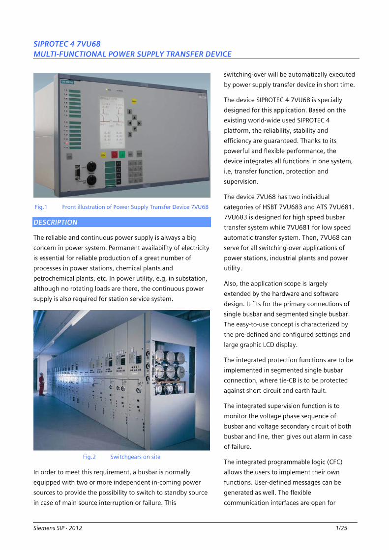
Fig.1 Front illustration of Power Supply Transfer Device 7VU68
DESCRIPTION
The reliable and continuous power supply is always a big
concern in power system. Permanent availability of electricity
is essential for reliable production of a great number of
processes in power stations, chemical plants and
petrochemical plants, etc. In power utility, e.g, in substation,
although no rotating loads are there, the continuous power
supply is also required for station service system.
Fig.2 Switchgears on site
In order to meet this requirement, a busbar is normally
equipped with two or more independent in-coming power
sources to provide the possibility to switch to standby source
in case of main source interruption or failure. This
switching-over will be automatically executed
by power supply transfer device in short time.
The device SIPROTEC 4 7VU68 is specially
designed for this application. Based on the
existing world-wide used SIPROTEC 4
platform, the reliability, stability and
efficiency are guaranteed. Thanks to its
powerful and flexible performance, the
device integrates all functions in one system,
i.e, transfer function, protection and
supervision.
The device 7VU68 has two individual
categories of HSBT 7VU683 and ATS 7VU681.
7VU683 is designed for high speed busbar
transfer system while 7VU681 for low speed
automatic transfer system. Then, 7VU68 can
serve for all switching-over applications of
power stations, industrial plants and power
utility.
Also, the application scope is largely
extended by the hardware and software
design. It fits for the primary connections of
single busbar and segmented single busbar.
The easy-to-use concept is characterized by
the pre-defined and configured settings and
large graphic LCD display.
The integrated protection functions are to be
implemented in segmented single busbar
connection, where tie-CB is to be protected
against short-circuit and earth fault.
The integrated supervision function is to
monitor the voltage phase sequence of
busbar and voltage secondary circuit of both
busbar and line, then gives out alarm in case
of failure.
The integrated programmable logic (CFC)
allows the users to implement their own
functions. User-defined messages can be
generated as well. The flexible
communication interfaces are open for
Multi-functional Power Supply Transfer Device/7VU68
2/25 Siemens SIP ⋅ 2012
modern communication architectures with remote control
center.
Transfer Functions
High speed transfer of category HSBT 7VU683, with high
speed relay contact for CB closing (only 1ms).
Low speed transfer of category ATS 7VU681
Protection Functions
Phase O/C Protection
Earth O/C Protection
Phase O/C Protection for Busbar Energization
Earth O/C Protection for Busbar Energization
Supervision Functions
Self-supervision of the device
Oscillographic fault recording
Voltage phase sequence of busbar
Voltage circuit monitoring of busbar and line
Communication Interfaces
PC front port for DIGSI setting, RS232
System Interface port B
- IEC 60870-5-103, ST / RS485
- IEC 60870-5-103, double RJ45
- IEC 61850, Ethernet, double LC / RJ45
- Modbus, ST / RS485
- Profibus-DP, ST / RS485
Rear service port C for remote DIGSI setting
Time synchronization port A – DCF 77/IRIG B
Language Support
English
Chinese
TYPICAL APPLICATIONS
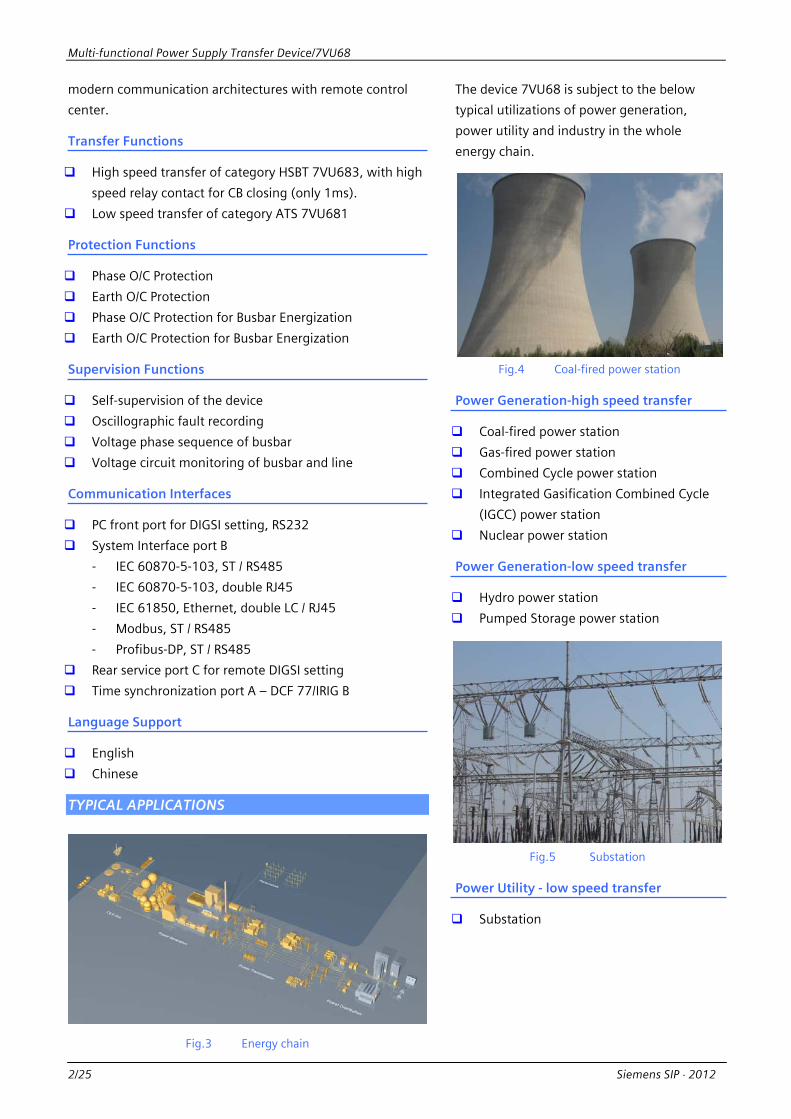
Fig.3 Energy chain
The device 7VU68 is subject to the below
typical utilizations of power generation,
power utility and industry in the whole
energy chain.
Fig.4 Coal-fired power station
Power Generation-high speed transfer
Coal-fired power station
Gas-fired power station
Combined Cycle power station
Integrated Gasification Combined Cycle
(IGCC) power station
Nuclear power station
Power Generation-low speed transfer
Hydro power station
Pumped Storage power station
Fig.5 Substation
Power Utility - low speed transfer
Substation

Multi-functional Power Supply Transfer Device/7VU68
Siemens SIP ⋅ 2012 3/25
Fig.6 Petrochemical plant
Industry
Chemical plant
Petrochemical plant
Refinery plant
Iron and steel plant
Cement plant
… …
APPLICATION 1 HIGH SPEED TRANSFER - HSBT 7VU683
For the auxiliary power supply of power stations and certain
industrial plants a safe medium voltage supply is extremely
important especially for rotating loads. In case of one source
interruption or failure, It’s required to quickly and safely
transfer the power supply to another source. In order to
ensure this, such medium voltage busbars are installed with
two or more independent incoming feeders to automatically
change the source of the power supply via automation
device, if necessary.
Such kind of automation equipment to secure the quick and
safe transfer of sources is called as High Speed Busbar
Transfer device (HSBT). Siemens is very early involved and
has tens-year long and experienced history in this field. The
technical leading solution type AUE series are now
world-widely used in power stations and industrial plants.
The category HSBT 7VU683 of Power Supply Transfer device
7VU68 is a compact solution based on type AUE series. It has
incorporated the latest concepts on high speed transfer, i.e,
various starting conditions, switching sequences and transfer
modes. Additionally, the protection functions for tie-CB in
application Segmented Single Busbar and the supervision
functions for voltage circuit are integrated.
Starting Conditions
The category HSBT 7VU683 is designed to
support the following staring conditions,
- NORMAL condition
- FAULT condition
- Inadmissible Under-voltage condition
- Inadmissible Under-frequency condition
- Inadvertent CB Open condition
The above conditions can be freely combined
together, i.e, one of them can be individually
switched “OFF”.
NORMAL condition
Under the NORMAL condition, the power
system is fault free and the starting
command must be manually issued. This
command can come from remote control
center and/or local controller via wiring
connection or communication over
protocol, e.g,
- DCS of power station
- Turbine control system
- Local panel
The switching of remote and local
starting authority is done by internal CFC
logic and controlled by device switching
key “Remote/Local”. The starting
command can only be remotely executed
over communication when the switching
key is at position “Remote”, vice versa.
FAULT condition
Under the FAULT condition, power
system fault must be there on the
in-feeder line and the starting command
must be externally issued by other device,
e.g, protection device.
Multi-functional Power Supply Transfer Device/7VU68
4/25 Siemens SIP ⋅ 2012
Abnormal condition
Under the abnormal condition, voltage disturbance must
be there on the busbar due to any causes. The starting
command can be internally issued by device HSBT
7VU683 according to the following abnormal conditions,
- Inadmissible Under-voltage
- Inadmissible Under-frequency
- Inadvertent CB Open
To secure the starting reliability, line current is used as
the additional criterion to the above conditions.
In case the operating CB is manually tripped, transfer
must not be started. This can be recognized via
indication 17864 “>NonManu.Op.CB1” and 17865
“>NonManu.Op.CB2” in configuration matrix.
Switching Sequences
The category HSBT 7VU683 is designed to serve for the
following switching sequences according to CBs’ operating
behavior,
- PARALLEL switching sequence
- SIMULTANEOUS switching sequence
- SEQUENTIAL switching sequence
PARALLEL and SIMULATEOUS switching sequences can
exclusively support the starting condition NORMAL while
SEQUENTIAL can support all starting conditions.
PARALLEL switching sequence
If the two sources are allowed to work on busbar in
parallel for a short time, the PARALLEL sequence can be
used for power supply transfer.
Under PARALLEL sequence, HSBT 7VU683 will firstly issue
a CLOSE command to the to-be-closed CB after the
device get the starting command. When the closure is
successful, the device will trip the to-be-opened CB. The
tripping command can be automatically generated by
device or derived from manual operation which are
dependent on setting,
- PARALLEL Auto sequence
- PARALLEL Half-Auto sequence
Under PARALLEL Auto sequence, the device will
automatically issue an OPEN command after a settable
time delay when the closure is successful. Under
PARALLE Half-Auto sequence, the device
will not issue the OPEN command until
the Manual Open command arrived. The
criterions are as below,
- df < 8851 “PARAL. Delta f”
- |dU| < 8852 “PARAL. Delta U”
- dϕ < 8853 “PARAL. Delta PHI”
If the to-be-opened CB failed to open, the
device will automatically de-couple the
to-be-closed CB.
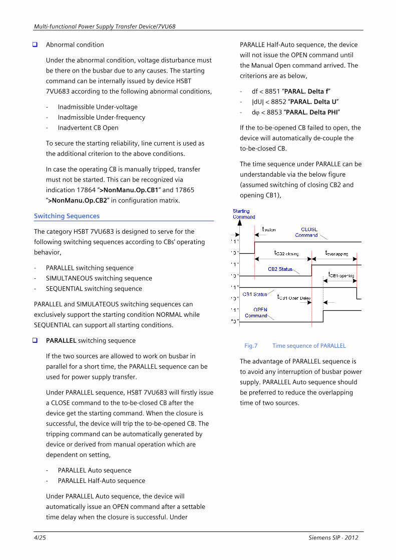
The time sequence under PARALLE can be
understandable via the below figure
(assumed switching of closing CB2 and
opening CB1),
Fig.7 Time sequence of PARALLEL
The advantage of PARALLEL sequence is
to avoid any interruption of busbar power
supply. PARALLEL Auto sequence should
be preferred to reduce the overlapping
time of two sources.

Multi-functional Power Supply Transfer Device/7VU68
Siemens SIP ⋅ 2012 5/25
SIMULTANEOUS switching sequence
If the two sources are not allowed to work on busbar in
parallel, the SIMULTANEOUS sequence
can be used for power supply transfer.
Under SIMULTANEOUS sequence, HSBT 7VU683 will
firstly issue a OPEN command to the to-be-opened CB
after the device gets the starting command. Meanwhile,
the device will issue a CLOSE command to the
to-be-closed CB if other criterions are met. The
overlapping can be avoided via the settable CB close time
delay if CB making time is small than breaking time. The
criterions are as below,
- df < 8855 “SIMUL. Delta f”
- dϕ < 8856 “SIMUL. Delta PHI”
If the to-be-opened CB failed to open, the device will
automatically de-couple the to-be-closed CB.
The time sequence under SIMULTANEOUS can be
understandable via the below figure (assumed switching
of closing CB2 and opening CB1),
Fig.8 Time sequence of SIMULTANEOUS
Due to the different operating time of the CB(a CB
normally opens faster than it close), the power supply of
busbar will be interrupted for a few milliseconds. The
length of this dead interval depends on the difference of
CB operating time.
SEQUENTIAL switching sequence
Under SEQUENTIAL sequence, HSBT 7VU683 will firstly
issue a OPEN command to the to-be-opened CB after the
device get the starting command. Differentiate from
PARALLEL and SIMULTANEOUS switching
sequences, SEQUENTIAL sequence can
only issue CLOSE command after the
opening succeeded.
The time sequence under SEQUENTIAL
can be understandable via the below
figure (assumed switching of closing CB2
and opening CB1),
“1 ”
“0 ”
“1 ”
“1 ”
“1 ”
“0 ”
“0 ”
“0 ”
tCB1-opening
tBB-dead
tCB1-closing
t
OPENCommand
CB2 Status
CB1 Status
CLOSECommand
Starting Command
taction
operating
Fig.9 Time sequence of SEQUENTIAL
Transfer Modes
In the station service system of power station
and industrial plants, lots of asynchronous
motors are connected. In case of the main
source interruption, the residual voltage of
busbar will be induced by connected
asynchronous motors. Fig.10 shows the
well-known typical diagram of vector
trajectory of residual voltage.

Multi-functional Power Supply Transfer Device/7VU68
6/25 Siemens SIP ⋅ 2012
I N- P
HA
SE
Tran
sfer
FAST
Tr
ansfe
r
REAL-TIME FAST
Transfer
REAL-TIME FAST
Trasnfer
dU
Safe AreaUn-safe Area
Uref
Ures
0.1s
0.2s
0.3s
0.4s
0.5s
0.6s
180°
210°
240°
270°
300°
330°
30°
60°
90°
120°
150°
CB
I
II
III
IV
V
0.7s
0.8s
A
Fig.10 Vector trajectory of residual voltage
Some notes are there regarding curve A according to Fig.10.
The amplitude and frequency of residual voltage will
decrease regarding time, while the delta phase angle against
referred voltage will increase. Fig.11 gives more messages to
differential voltage.
Fig.11 Characteristic of vector dU
The equivalent circuit of residual voltage Ures and referred
voltage Uref is shown in Fig.11.
The voltage drop on motor Um at instant of CB closing is
calculated by following,
Um = dU⋅xm /(xm +xs) = k⋅ dU (Equa.-1)
Here, xm and xs are respectively the
equivalent reactance of busbar loading and
referred system.
Fig.12 Equivalent circuit of dU
For safety reason, the value |Um| must not
exceed the permissible voltage ko/v⋅|Un.|, Then,
the maximum of permissible differential
voltage |dU|max will be,
|dU|max = ko/v/k⋅|Un| (Equa.-2)
In case ko/v = 1.1 and k = 0.67, the calculated
|dU|max should be less than 1.64⋅|Un| (refer to
curve B in Fig.10). In case ko/v = 1.1 and k =
0.95, the calculated |dU|max should be less
than 1.15⋅|Un| (refer to curve C in Fig.10).
This calculation result would be the base for
setting.
The plane is divided into two parts by curve B
(or curve C). The left is defined as un-safe
area because the value |dU| is bigger than the
up-limit |dU|max which could damage the
winding of stator. Vice versa, the right is safe
area.
Based on the above principles, the category
HSBT 7VU683 is designed to have the
following modes (refer to Fig.10) to fit for the
safe transfer,
- FAST transfer mode (area I)
- REAL-TIME FAST transfer mode (area II
and IV)
- IN-PHASE transfer mode (area V)
- RES-VOLT transfer mode
- LONG-TIME transfer mode

Multi-functional Power Supply Transfer Device/7VU68
Siemens SIP ⋅ 2012 7/25
All of above modes can be freely combined together, i.e, one
of them can be individually switched “ON” or “OFF” remotely
via communication or locally at device panel.
To be noted that the original dϕ and |dU| between busbar
voltage and standby voltage due to wiring can be
automatically compensated by device during configuration.
FAST transfer mode
The study and testing results show, in most cases the
typical values of df, dϕ and |dU| are smaller enough
within the first tens of millisecond from the instant the
CB opens. It’s good to safe and fast transfer due to the
slight shock to motors. If the real-time measured df, dϕ
and |Ures| meet the defined criterions, the device will
immediately issue the CLOSE command to the
to-be-closed CB. The criterions are as below,
- df < 8858 ” FT Delta f” - dϕ < 8859 “FT Delta PHI“ - |Ures| > 8860 “FT U/V BLK“
The typical operating time of 7VU683 in this case is
approx.20ms. As modern vacuum breaker has less
making time, e.g, 60ms, the dead time of busbar will be
as short as approx.80ms.
REAL-TIME FAST transfer mode
When FAST transfer chance is missed, the device will
automatically, if activated, turn to next transfer mode
REAL-TIME FAST.
This mode has more concerning on the permissible
motor voltage, i.e, the differential voltage |dU| across the
opened CB must not exceed the value |dU|max. The
intelligent device 7VU683 then estimates the delta phase
angle dϕ and differential voltage dU at the instant the CB
closes based on real-time slipping rate and the settable
“CBx Closing Time”. If all the quantity of predicted
dϕ and dU, the real-time df and |Ures| meet the defined
criterions, the device will immediately issue the CLOSE
command to the to-be-closed CB. The criterions are as
below,
- df < 8861 ” FT Delta f”
- |dU| < 8862 “RTFT Delta U“ - dϕ < 8863 “FT Delta PHI“ - |Ures| > 8864 “RTFT U/V BLK“
IN-PHASE transfer mode
When the residual voltage comes close to
the referred voltage, it comes to transfer
mode IN-PHASE. It’s good for safe transfer
if the CB closes at the instant the value dϕ
is zero.
The intelligent device 7VU683 estimates
the delta phase angle dϕ at the instant
the CB closes. based on real-time slipping
rate and the settable “CBx Closing Time”.
If If all the quantity of predicted dϕ, the
real-time df and |Ures| meet the defined
criterions,, the device will immediately
issue the CLOSE command to the
to-be-closed CB. The criterions are as
below,
- df < 8868 ” IN-PHA Delta f”
- dϕ < 8869 “IN-PHA Delta PHI“
- |Ures| > 8870 “IN-PHA U/V BLK“
RES-VOLT transfer mode
If the above mentioned transfer modes
failed, the transfer can still go on with
mode RES-VOLT.
When the residual voltage |Ures|
under-shots the settable parameter 8871
“RES-VOLT Threshold”, the RES-VOLT
transfer mode will perform and the
device will immediately issue the CLOSE
command to the to-be-closed CB. The
typical setting could be 30%Un.
To reduce the shock under low voltage
restarting of motors, two stages of Low
Voltage Load-Shedding (LVLSH) function
are integrated in the device. LVLSH will
pickup before the RES-VOLT transfer
mode. This function can be activated or
de-activated manually on site.
LONG-TIME transfer mode
The last criterion to start the transfer is
LONG-TIME mode if all above mentioned
modes failed.
Multi-functional Power Supply Transfer Device/7VU68
8/25 Siemens SIP ⋅ 2012
When the transfer time is more than the settable
parameter 8872 “LONG-TIME Threshold”, the
LONG-TIME transfer mode will perform and the device
will immediately issue the CLOSE
command to the to-be-closed CB. The
typical setting could be 3s
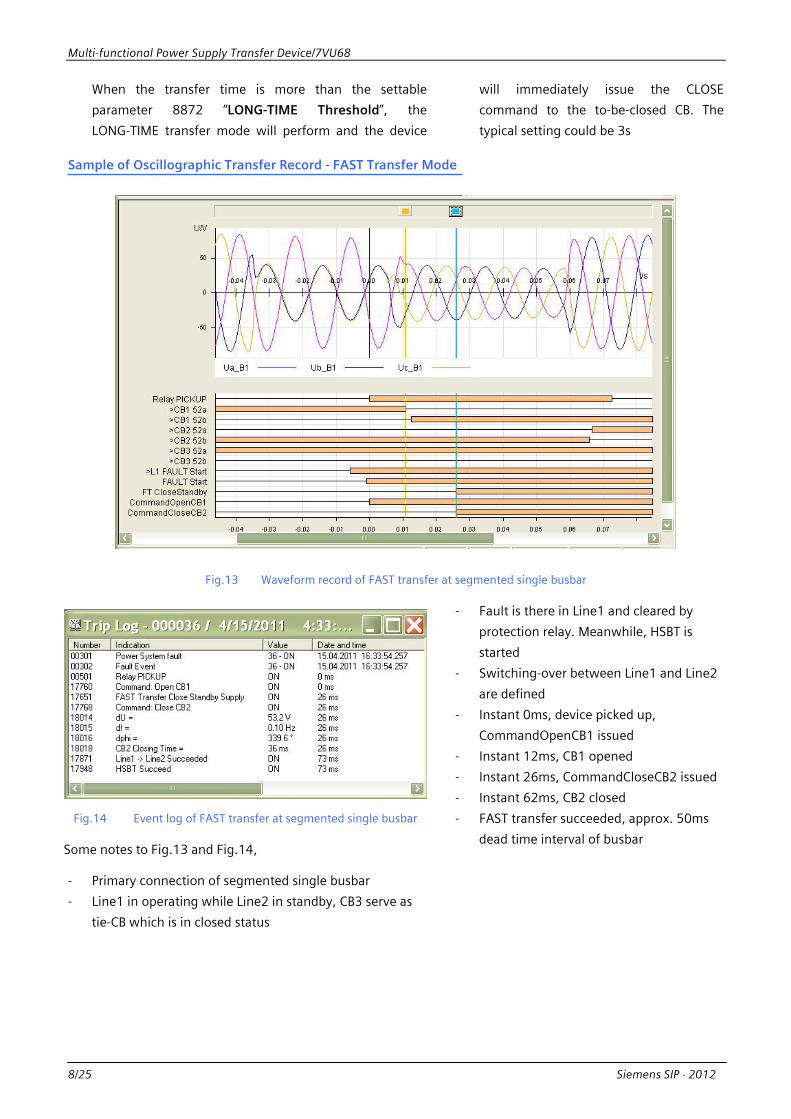
Sample of Oscillographic Transfer Record - FAST Transfer Mode
Fig.13 Waveform record of FAST transfer at segmented single busbar
Fig.14 Event log of FAST transfer at segmented single busbar
Some notes to Fig.13 and Fig.14,
- Primary connection of segmented single busbar
- Line1 in operating while Line2 in standby, CB3 serve as
tie-CB which is in closed status
- Fault is there in Line1 and cleared by
protection relay. Meanwhile, HSBT is
started
- Switching-over between Line1 and Line2
are defined
- Instant 0ms, device picked up,
CommandOpenCB1 issued
- Instant 12ms, CB1 opened
- Instant 26ms, CommandCloseCB2 issued
- Instant 62ms, CB2 closed
- FAST transfer succeeded, approx. 50ms
dead time interval of busbar

Multi-functional Power Supply Transfer Device/7VU68
Siemens SIP ⋅ 2012 9/25
Switching Directions and Wiring Diagrams
Primary connection of single busbar
J1 J2 J5J6R15
R17
R18
R16
R13
R14
K13
K14
Ua_
BU
b_B
Uc_
B
Ix_L
1
Ix_L
2
Ux_
L1
Ux_
L2
Ope
n跳
Clo
se合
BO
11
BO
6
CT1
CT2
Fig.15 Switching-over L1->L2, single busbar
J1 J2 J5J6R15
R17
R18
R16
R13
R14
K13
K14
Ua_
BU
b_B
Uc_
B
Ix_L
1
Ix_L
2
Ux_
L1
Ux_
L2
Ope
n跳
Clo
se合
BO
13
BO
10
CT1
CT2
Fig.16 Switching-over L2->L1, single busbar
The device HSBT 7VU683 will automatically determine
the switching direction based on the actual CBs’ status.
The above switching-overs can be individually switched
“ON” or “OFF” remotely via
communication or locally at device panel.

Multi-functional Power Supply Transfer Device/7VU68
10/25 Siemens SIP ⋅ 2012
Primary connection of segmented single busbar: CB1 and CB3 are closed, CB2 is opened
Q3
Q4
Q2
Q1
Q5
Q6
Q8
Q7
J1 J2 J5J6R15
R17
R18
R16
R13
R14
K15
K17
K18
K16
K13
K14
Ua_
B1
Ub_
B1
Uc_
B1
Ix_L
1
Ix_L
2
Ie_B
Ic_B
Ib_B
Ia_B
Uc_
B2
Ub_
B2
Ua_
B2
Ux_
L1
Ux_
L2
Ope
n跳
Clo
se合
BO
11
BO
6
CT1
CT2
Fig.17 Switching-over L1->L2, segmented single busbar Q
3Q
4Q
2Q
1
Q5
Q6
Q8
Q7
J1 J2 J5J6R15
R17
R18
R16
R13
R14
K15
K17
K18
K16
K13
K14
Ua_
B1
Ub_
B1
Uc_
B1
Ix_L
1
Ix_L
2
Ie_B
Ic_B
Ib_B
Ia_B
Uc_
B2
Ub_
B2
Ua_
B2
Ux_
L1
Ux_
L2
Ope
n跳
Clo
se合
BO
11
BO
5
CT1
CT2
Fig.18 Switching-over B2->L2, segmented single busbar
In case of these CBs’ status, two possible switching
directions are there. Then, the starting command of two
switching directions must be externally separately routed
to device’s binary inputs, e.g, starting command L1->L2
routed to BI13, B2->L2 to BI12. The device will properly
execute the switching direction based on the command
input under this case.
The above switching-overs can be
individually switched “ON” or “OFF”
remotely via communication or locally at
device panel.
Multi-functional Power Supply Transfer Device/7VU68
Siemens SIP ⋅ 2012 11/25
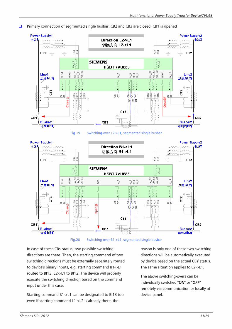
Primary connection of segmented single busbar: CB2 and CB3 are closed, CB1 is opened
Q3
Q4
Q2
Q1
Q5
Q6
Q8
Q7
J1 J2 J5J6R15
R17
R18
R16
R13
R14
K15
K17
K18
K16
K13
K14
Ua_
B1
Ub_
B1
Uc_
B1
Ix_L
1
Ix_L
2
Ie_B
Ic_B
Ib_B
Ia_B
Uc_
B2
Ub_
B2
Ua_
B2
Ux_
L1
Ux_
L2
Ope
n跳
Clo
se合
BO
10
BO
13
CT1
CT2
Fig.19 Switching-over L2->L1, segmented single busbar Q
3Q
4Q
2Q
1
Q5
Q6
Q8
Q7
J1 J2 J5J6R15
R17
R18
R16
R13
R14
K15
K17
K18
K16
K13
K14
Ua_
B1
Ub_
B1
Uc_
B1
Ix_L
1
Ix_L
2
Ie_B
Ic_B
Ib_B
Ia_B
Uc_
B2
Ub_
B2
Ua_
B2
Ux_
L1
Ux_
L2
Ope
n跳
BO
10C
lose合
BO
5
CT1
CT2
Fig.20 Switching-over B1->L1, segmented single busbar
In case of these CBs’ status, two possible switching
directions are there. Then, the starting command of two
switching directions must be externally separately routed
to device’s binary inputs, e.g, starting command B1->L1
routed to BI13, L2->L1 to BI12. The device will properly
execute the switching direction based on the command
input under this case.
Starting command B1->L1 can be designated to BI13 too
even if starting command L1->L2 is already there, the
reason is only one of these two switching
directions will be automatically executed
by device based on the actual CBs’ status.
The same situation applies to L2->L1.
The above switching-overs can be
individually switched “ON” or “OFF”
remotely via communication or locally at
device panel.
Multi-functional Power Supply Transfer Device/7VU68
12/25 Siemens SIP ⋅ 2012
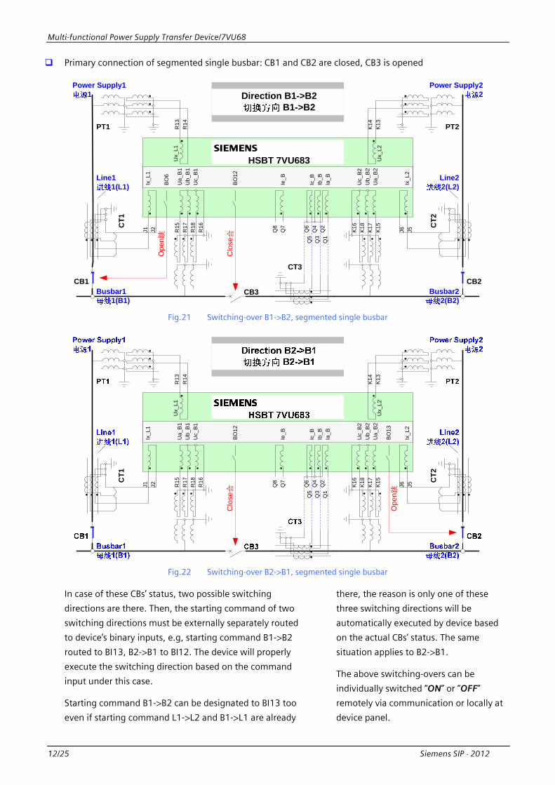
Primary connection of segmented single busbar: CB1 and CB2 are closed, CB3 is opened
Busbar22(B2)
Busbar11(B1)
PT2PT1
Q3
Q4
Q2
Q1
Q5
Q6
Q8
Q7
J1 J2 J5J6R15
R17
R18
R16
R13
R14
K15
K17
K18
K16
K13
K14
Ua_
B1
Ub_
B1
Uc_
B1
Ix_L
1
Ix_L
2
Ie_B
Ic_B
Ib_B
Ia_B
Uc_
B2
Ub_
B2
Ua_
B2
Ux_
L1
Ux_
L2
HSBT 7VU683s
Clo
se合
Direction B1->B2 B1->B2
BO
12
CB1 CB2
CT1
CT2
CT3
CB3
Line11(L1)
Line22(L2)
Power Supply11
Power Supply22
Ope
n跳B
O6
Fig.21 Switching-over B1->B2, segmented single busbar Q
3Q
4Q
2Q
1
Q5
Q6
Q8
Q7
J1 J2 J5J6R15
R17
R18
R16
R13
R14
K15
K17
K18
K16
K13
K14
Ua_
B1
Ub_
B1
Uc_
B1
Ix_L
1
Ix_L
2
Ie_B
Ic_B
Ib_B
Ia_B
Uc_
B2
Ub_
B2
Ua_
B2
Ux_
L1
Ux_
L2
Ope
n跳
Clo
se合
BO
12
BO
13
CT1
CT2
Fig.22 Switching-over B2->B1, segmented single busbar
In case of these CBs’ status, two possible switching
directions are there. Then, the starting command of two
switching directions must be externally separately routed
to device’s binary inputs, e.g, starting command B1->B2
routed to BI13, B2->B1 to BI12. The device will properly
execute the switching direction based on the command
input under this case.
Starting command B1->B2 can be designated to BI13 too
even if starting command L1->L2 and B1->L1 are already
there, the reason is only one of these
three switching directions will be
automatically executed by device based
on the actual CBs’ status. The same
situation applies to B2->B1.
The above switching-overs can be
individually switched “ON” or “OFF”
remotely via communication or locally at
device panel.
Multi-functional Power Supply Transfer Device/7VU68
Siemens SIP ⋅ 2012 13/25
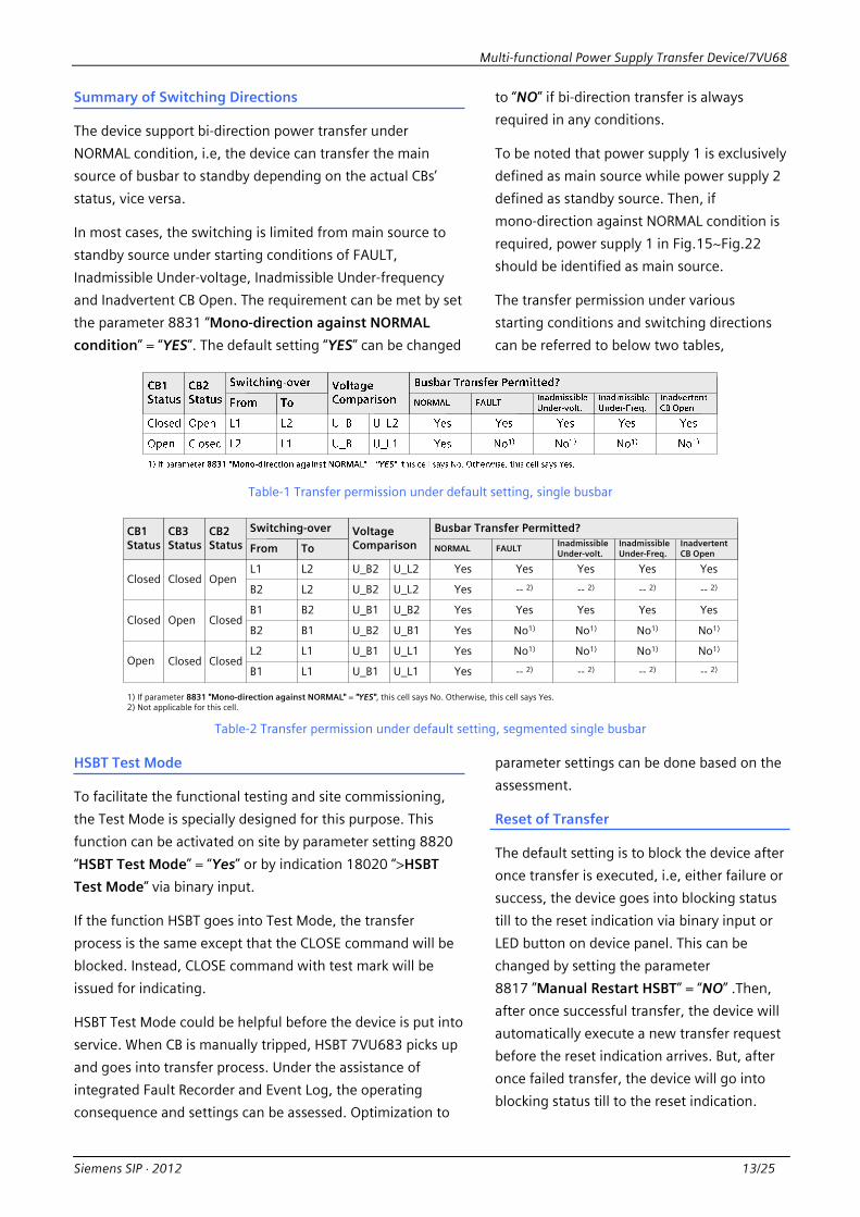
Summary of Switching Directions
The device support bi-direction power transfer under
NORMAL condition, i.e, the device can transfer the main
source of busbar to standby depending on the actual CBs’
status, vice versa.
In most cases, the switching is limited from main source to
standby source under starting conditions of FAULT,
Inadmissible Under-voltage, Inadmissible Under-frequency
and Inadvertent CB Open. The requirement can be met by set
the parameter 8831 “Mono-direction against NORMAL
condition” = “YES”. The default setting “YES” can be changed
to “NO” if bi-direction transfer is always
required in any conditions.
To be noted that power supply 1 is exclusively
defined as main source while power supply 2
defined as standby source. Then, if
mono-direction against NORMAL condition is
required, power supply 1 in Fig.15~Fig.22
should be identified as main source.
The transfer permission under various
starting conditions and switching directions
can be referred to below two tables,
Table-1 Transfer permission under default setting, single busbar
CB1Status
CB2Status
CB3Status
Closed Closed Open
Closed Closed
Closed ClosedOpen
Open
Switching-over Voltage Comparison
Busbar Transfer Permitted?
From To NORMAL FAULT
L1
B2
L2
L2
B2
B2
B1
B1
L2 L1
B1 L1
U_B2 U_L2
U_B2 U_L2
U_B2
U_B2
U_B1
U_B1
U_B1
U_B1
U_L1
U_L1
Yes Yes
Yes
Yes
Yes
Yes
Yes
No1)
No1)
-- 2)
Yes
Inadvertent CB Open
1) If parameter 8831 "Mono-direction against NORMAL" = "YES", this cell says No. Otherwise, this cell says Yes.
Yes
No1)
Yes
No1)
Yes
No1)
Yes
No1)
Yes
No1)
Yes
No1)
InadmissibleUnder-volt.
InadmissibleUnder-Freq.
2) Not applicable for this cell.
-- 2) -- 2) -- 2)
-- 2) -- 2) -- 2) -- 2)
Table-2 Transfer permission under default setting, segmented single busbar
HSBT Test Mode
To facilitate the functional testing and site commissioning,
the Test Mode is specially designed for this purpose. This
function can be activated on site by parameter setting 8820
“HSBT Test Mode” = “Yes” or by indication 18020 “>HSBT
Test Mode” via binary input.
If the function HSBT goes into Test Mode, the transfer
process is the same except that the CLOSE command will be
blocked. Instead, CLOSE command with test mark will be
issued for indicating.
HSBT Test Mode could be helpful before the device is put into
service. When CB is manually tripped, HSBT 7VU683 picks up
and goes into transfer process. Under the assistance of
integrated Fault Recorder and Event Log, the operating
consequence and settings can be assessed. Optimization to
parameter settings can be done based on the
assessment.
Reset of Transfer
The default setting is to block the device after
once transfer is executed, i.e, either failure or
success, the device goes into blocking status
till to the reset indication via binary input or
LED button on device panel. This can be
changed by setting the parameter
8817 ”Manual Restart HSBT” = “NO” .Then,
after once successful transfer, the device will
automatically execute a new transfer request
before the reset indication arrives. But, after
once failed transfer, the device will go into
blocking status till to the reset indication.

Multi-functional Power Supply Transfer Device/7VU68
Siemens SIP ⋅ 2012 14/25
APPLICATION 2 LOW SPEED TRANSFER - ATS 7VU681
In some applications, e.g, hydro power station or substation,
the continuous power supply is required for station service
system in case of power supply failure. The transfer time is
not critically assessed for non-rotating loads.
To support the automatic and smooth transfer of sources, the
called Automatic Transfer System (ATS) is necessary. The ATS
can be realized by intelligent electronic devices (IEDs)
installed at MV switchgears via programmable logic. Siemens
now provide the compact solution, that is, integrates all
necessary measurements, logic binary inputs, binary outputs
and wiring into one device ATS 7VU681.
The category ATS 7VU681 of Power Supply Transfer device
7VU68 is designed to support broad applications under the
easy-to-use concept. Additionally, the protection functions
for tie-CB in application Segmented Single Busbar and the
supervision functions for voltage circuit are integrated.
General
The pre-condition to ATS starting is that the device is in
Ready status, i.e, the standby source is live, the relative CBs’
status is proper, no external blocking indication is there, etc.
Oppositely, the device will go into blocking status and any
transfer request will be rejected.
The starting of ATS will be internally and automatically
executed by device 7VU681 based on the settable
parameters. The main criterions are referred to the line
voltage and busbar voltage. To secure the starting reliability,
line current is used as the additional criterion.
In case the operating CB is manually tripped, transfer must
not be started. This can be recognized via indication 17864
“>NonManu.Op.CB1” or 17865 “>NonManu.Op.CB2” in
configuration matrix.
If one transfer is executed, either failure or success, the
device goes into blocking status till to the reset indication via
binary input or LED button on device panel. This can be
changed by setting the parameter 0231 ”Manual Restart
ATS” = “NO” , then, after once successful transfer, the device
will automatically execute a new transfer request before the
reset indication arrives. But, after once failed transfer, the
device will go into blocking status till to the reset indication.
The device ATS 7VU681 has pre-configured
eight transfer modes, see Fig.23~Fig.36. Each
of them can be individually switched “ON” or
“OFF” remotely via communication or locally
at device panel. If other transfers are required,
device integrated programmable logic CFC
can be practical.
Load-Shedding
If standby transformer has smaller capacity
than main transformer, the overloading of
the standby transformer could be there after
the completion of transfer. Rejecting some
loads will be helpful. The integrated
Load-Shedding function is specially designed
for this utilization.
To over-shot the line current will cause the
pickup of Load-Shedding. Depends on the
transfer mode, the device will automatically
determine which line current will be used.
The function Load-Shedding can be
individually activated or de-activated under
each transfer mode. It has one stage with two
time delays, each time delay can be
separately configured to binary output to fit
for various load-shedding’ plans.
Load-Shifting
In some complex primary connection (see
Fig.35), switching will perform among
multi-CBs. If the overloading of the standby
transformer must be there after the
completion of transfer, shifting some loads to
other busbar will be helpful. The integrated
Load-Shifting function is specially designed
for this utilization.
This function can be individually switched
“ON” or “OFF” remotely via communication or
locally at device panel.

Multi-functional Power Supply Transfer Device/7VU68
Siemens SIP ⋅ 2012 15/25
Transfer Modes and Wiring Diagrams
Primary connection of segmented single busbar: CB1, CB3, CB4 and CB5 are closed, CB2 is opened
CT1
Q3
Q4
Q2
Q1
Q5
Q6
Q8
Q7
J1 J2 J5J6R15
R17
R18
R16
R13
R14
K15
K17
K18
K16
K13
K14
Ua_
B1
Ub_
B1
Uc_
B1
Ix_L
1
Ix_L
2
Ie_B
Ic_B
Ib_B
Ia_B
Uc_
B2U
b_B
2U
a_B
2
Ux_
L1
Ux_
L2
Clo
se合
BO
11
BO
6B
O10
BO
17
BO
15B
O14
BO
18
BO
13
BO
5B
O12
Ope
n跳
Tran
sfor
mer
11(
T1)
CT2
Tran
sfor
mer
22(
T2)
Fig.23 Switching-over L1->L2
Basic criterions to Ready status, “AND” logic
- CB1 and CB3 in closing status, CB2 in opening status
- U_B1 > 8900 “Busbar Live Voltage Threshold”
- U_B2 > 8900 “Busbar Live Voltage Threshold”
- Ux_L2 > 8902 ”Line Live Voltage Threshold”
If 0214 “PT Connection L2” = “Not connected”, then L2
will be seen as live.
Basic criterions for ATS pickup, “AND” logic
- U_B1 < 8901 “Busbar Dead Voltage Threshold”
- U_B2 < 8901 “Busbar Dead Voltage Threshold”
- Ix_L1 < 8904 “Line Dead Current Threshold”
- Ux_L2 > 8902 ”Line Live Voltage Threshold”
The transfer will be immediately terminated as soon as
the device goes into Un-Ready status. Basic criterions are
as below, “OR” logic
- CB1 in opening status
- CB3 in opening status
- U_B1 > 8900 “Busbar Live Voltage
Threshold”
- U_B2 > 8900 “Busbar Live Voltage
Threshold”
- Dropout of Ux_L2 > 8902 ”Line Live
Voltage Threshold”
Operating consequence, see Fig.24
Fig.24 Operating consequence L1->L2
Multi-functional Power Supply Transfer Device/7VU68
16/25 Siemens SIP ⋅ 2012
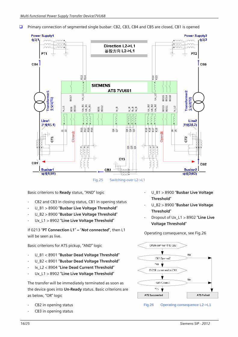
Primary connection of segmented single busbar: CB2, CB3, CB4 and CB5 are closed, CB1 is opened
CT1
Q3
Q4
Q2
Q1
Q5
Q6
Q8
Q7
J1 J2 J5J6R15
R17
R18
R16
R13
R14
K15
K17
K18
K16
K13
K14
Ua_
B1U
b_B1
Uc_
B1
Ix_L
1
Ix_L
2
Ie_B
Ic_B
Ib_B
Ia_B
Uc_
B2
Ub_
B2U
a_B2
Ux_
L1
Ux_
L2
BO
11
BO
6B
O10
BO
17
BO
15B
O14
BO
18
BO
13
BO
5B
O12
Ope
n跳
Clo
se合
Tran
sfor
mer
11(
T1)
CT2
Tran
sfor
mer
22(
T2)
Fig.25 Switching-over L2->L1
Basic criterions to Ready status, “AND” logic
- CB2 and CB3 in closing status, CB1 in opening status
- U_B1 > 8900 “Busbar Live Voltage Threshold”
- U_B2 > 8900 “Busbar Live Voltage Threshold”
- Ux_L1 > 8902 ”Line Live Voltage Threshold”
If 0213 “PT Connection L1” = “Not connected”, then L1
will be seen as live.
Basic criterions for ATS pickup, “AND” logic
- U_B1 < 8901 “Busbar Dead Voltage Threshold”
- U_B2 < 8901 “Busbar Dead Voltage Threshold”
- Ix_L2 < 8904 “Line Dead Current Threshold”
- Ux_L1 > 8902 ”Line Live Voltage Threshold”
The transfer will be immediately terminated as soon as
the device goes into Un-Ready status. Basic criterions are
as below, “OR” logic
- CB2 in opening status
- CB3 in opening status
- U_B1 > 8900 “Busbar Live Voltage
Threshold”
- U_B2 > 8900 “Busbar Live Voltage
Threshold”
- Dropout of Ux_L1 > 8902 ”Line Live
Voltage Threshold”
Operating consequence, see Fig.26
Fig.26 Operating consequence L2->L1
Multi-functional Power Supply Transfer Device/7VU68
Siemens SIP ⋅ 2012 17/25
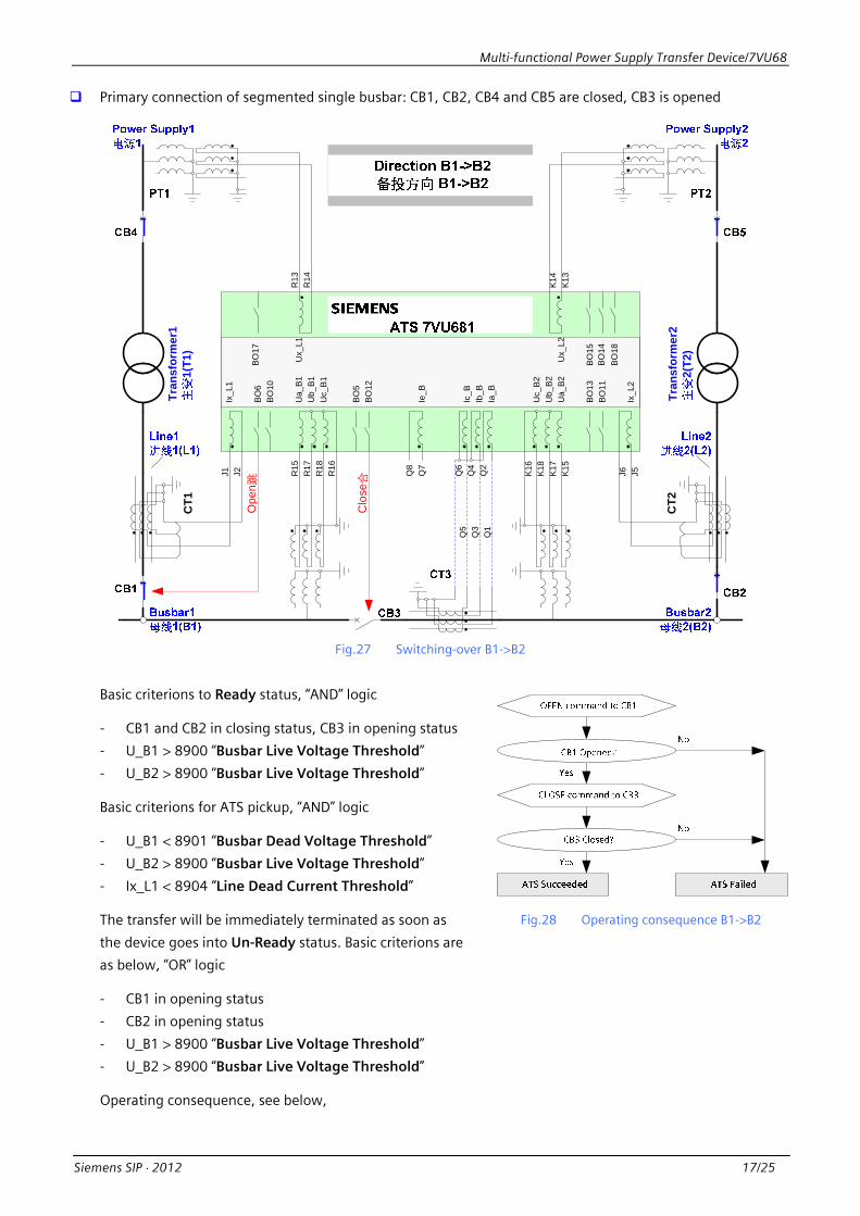
Primary connection of segmented single busbar: CB1, CB2, CB4 and CB5 are closed, CB3 is opened
CT1
Q3
Q4
Q2
Q1
Q5
Q6
Q8
Q7
J1 J2 J5J6R15
R17
R18
R16
R13
R14
K15
K17
K18
K16
K13
K14
Ua_
B1U
b_B1
Uc_
B1
Ix_L
1
Ix_L
2
Ie_B
Ic_B
Ib_B
Ia_B
Uc_
B2
Ub_
B2U
a_B2
Ux_
L1
Ux_
L2
BO
11
BO
6B
O10
BO
17
BO
15B
O14
BO
18
BO
13
BO
5B
O12
Ope
n跳
Clo
se合
Tran
sfor
mer
11(
T1)
CT2
Tran
sfor
mer
22(
T2)
Fig.27 Switching-over B1->B2
Basic criterions to Ready status, “AND” logic
- CB1 and CB2 in closing status, CB3 in opening status
- U_B1 > 8900 “Busbar Live Voltage Threshold”
- U_B2 > 8900 “Busbar Live Voltage Threshold”
Basic criterions for ATS pickup, “AND” logic
- U_B1 < 8901 “Busbar Dead Voltage Threshold”
- U_B2 > 8900 “Busbar Live Voltage Threshold”
- Ix_L1 < 8904 “Line Dead Current Threshold”
The transfer will be immediately terminated as soon as
the device goes into Un-Ready status. Basic criterions are
as below, “OR” logic
- CB1 in opening status
- CB2 in opening status
- U_B1 > 8900 “Busbar Live Voltage Threshold”
- U_B2 > 8900 “Busbar Live Voltage Threshold”
Operating consequence, see below,
Fig.28 Operating consequence B1->B2
Multi-functional Power Supply Transfer Device/7VU68
18/25 Siemens SIP ⋅ 2012
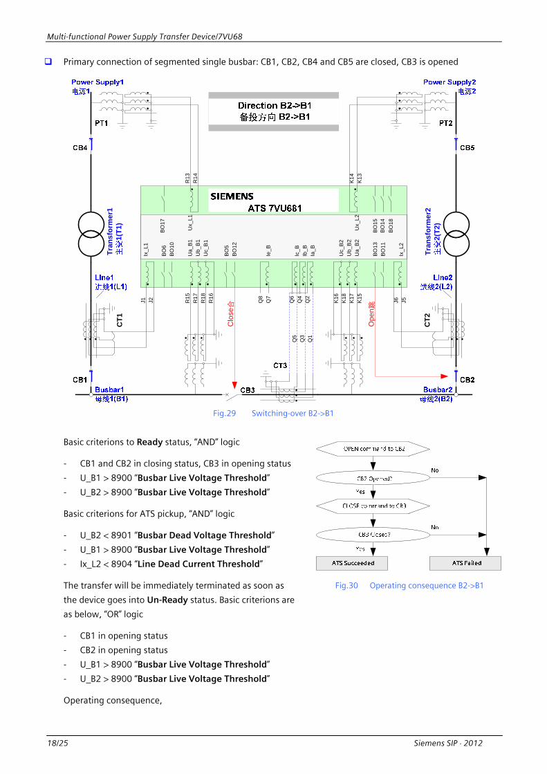
Primary connection of segmented single busbar: CB1, CB2, CB4 and CB5 are closed, CB3 is opened
CT1
Q3
Q4
Q2
Q1
Q5
Q6
Q8
Q7
J1 J2 J5J6R15
R17
R18
R16
R13
R14
K15
K17
K18
K16
K13
K14
Ua_
B1
Ub_
B1
Uc_
B1
Ix_L
1
Ix_L
2
Ie_B
Ic_B
Ib_B
Ia_B
Uc_
B2
Ub_
B2
Ua_
B2
Ux_
L1
Ux_
L2
BO
11
BO
6B
O10
BO17
BO15
BO14
BO18
BO
13
BO
5B
O12
Clo
se合
Tran
sfor
mer
11(
T1)
CT2
Tran
sfor
mer
22(
T2)
Ope
n跳
Fig.29 Switching-over B2->B1
Basic criterions to Ready status, “AND” logic
- CB1 and CB2 in closing status, CB3 in opening status
- U_B1 > 8900 “Busbar Live Voltage Threshold”
- U_B2 > 8900 “Busbar Live Voltage Threshold”
Basic criterions for ATS pickup, “AND” logic
- U_B2 < 8901 “Busbar Dead Voltage Threshold”
- U_B1 > 8900 “Busbar Live Voltage Threshold”
- Ix_L2 < 8904 “Line Dead Current Threshold”
The transfer will be immediately terminated as soon as
the device goes into Un-Ready status. Basic criterions are
as below, “OR” logic
- CB1 in opening status
- CB2 in opening status
- U_B1 > 8900 “Busbar Live Voltage Threshold”
- U_B2 > 8900 “Busbar Live Voltage Threshold”
Operating consequence,
Fig.30 Operating consequence B2->B1
Multi-functional Power Supply Transfer Device/7VU68
Siemens SIP ⋅ 2012 19/25
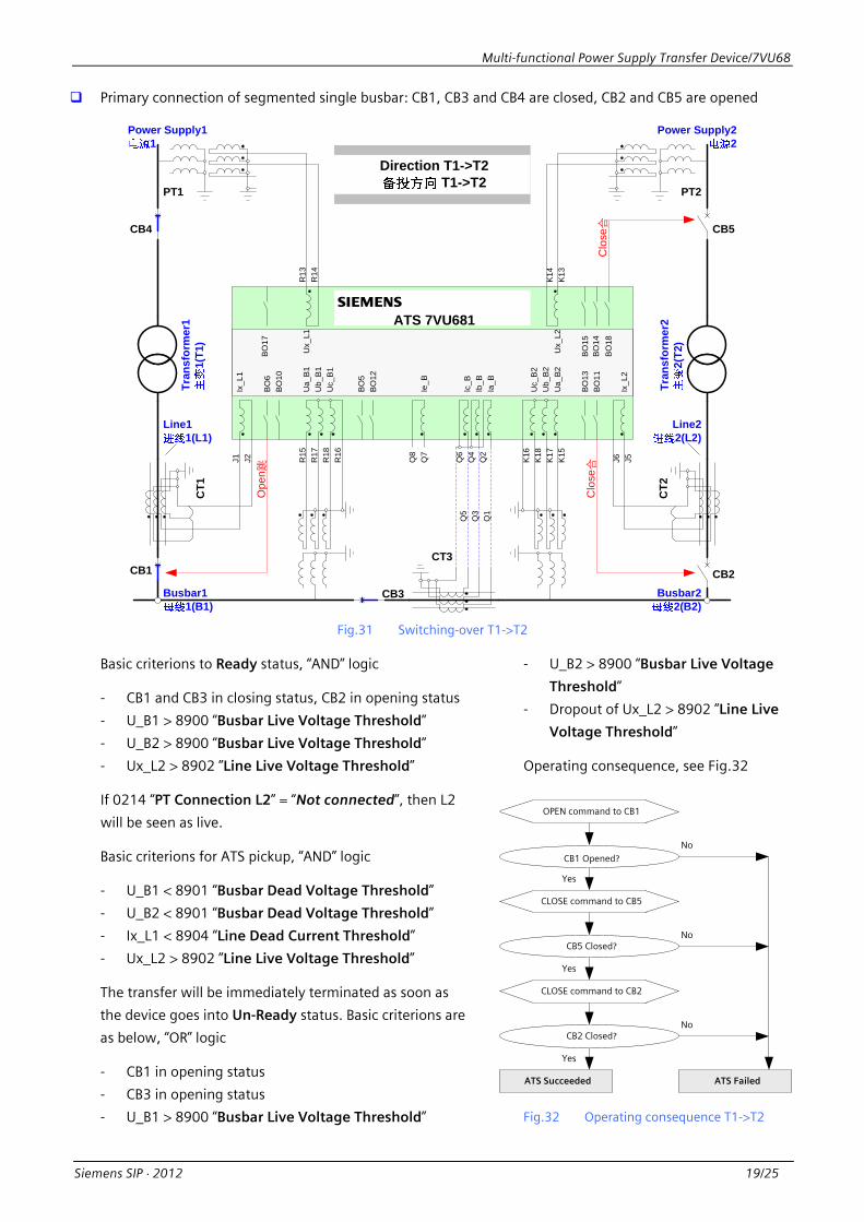
Primary connection of segmented single busbar: CB1, CB3 and CB4 are closed, CB2 and CB5 are opened
CB1
Line11(L1)
Busbar22(B2)
Busbar11(B1)
CB2
CB3
CT1
PT1
Q3
Q4
Q2
Q1
Q5
Q6
Q8
Q7
J1 J2 J5J6R15
R17
R18
R16
R13
R14
K15
K17
K18
K16
K13
K14
Ua_
B1
Ub_
B1
Uc_
B1
Ix_L
1
Ix_L
2
Ie_B
Ic_B
Ib_B
Ia_B
Uc_
B2
Ub_
B2
Ua_
B2
Ux_
L1
Ux_
L2
ATS 7VU681s
Clo
se合
BO
11
BO
6B
O10
BO
17
BO
15B
O14
BO
18
BO
13
BO
5B
O12
Ope
n跳
CB4 CB5
Tran
sfor
mer
11(
T1)
PT2
CT2
CT3
Tran
sfor
mer
22(
T2)
Line22(L2)
Direction T1->T2 T1->T2
Clo
se合
Power Supply11
Power Supply22
Fig.31 Switching-over T1->T2
Basic criterions to Ready status, “AND” logic
- CB1 and CB3 in closing status, CB2 in opening status
- U_B1 > 8900 “Busbar Live Voltage Threshold”
- U_B2 > 8900 “Busbar Live Voltage Threshold”
- Ux_L2 > 8902 ”Line Live Voltage Threshold”
If 0214 “PT Connection L2” = “Not connected”, then L2
will be seen as live.
Basic criterions for ATS pickup, “AND” logic
- U_B1 < 8901 “Busbar Dead Voltage Threshold”
- U_B2 < 8901 “Busbar Dead Voltage Threshold”
- Ix_L1 < 8904 “Line Dead Current Threshold”
- Ux_L2 > 8902 ”Line Live Voltage Threshold”
The transfer will be immediately terminated as soon as
the device goes into Un-Ready status. Basic criterions are
as below, “OR” logic
- CB1 in opening status
- CB3 in opening status
- U_B1 > 8900 “Busbar Live Voltage Threshold”
- U_B2 > 8900 “Busbar Live Voltage
Threshold”
- Dropout of Ux_L2 > 8902 ”Line Live
Voltage Threshold”
Operating consequence, see Fig.32
OPEN command to CB1
CB1 Opened?
CLOSE command to CB5
Yes
No
CB5 Closed?No
Yes
ATS Succeeded ATS Failed
CLOSE command to CB2
CB2 Closed?
Yes
No
Fig.32 Operating consequence T1->T2
Multi-functional Power Supply Transfer Device/7VU68
20/25 Siemens SIP ⋅ 2012
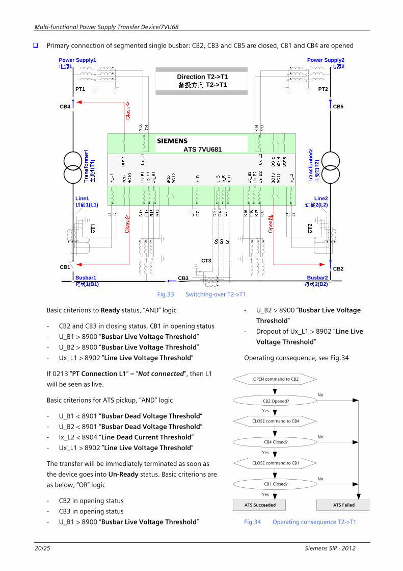
Primary connection of segmented single busbar: CB2, CB3 and CB5 are closed, CB1 and CB4 are opened
CB1
Line11(L1)
Busbar22(B2)
Busbar11(B1)
CB2
CB3
PT1
ATS 7VU681s
CB4 CB5
PT2
CT3
Line22(L2)
Direction T2->T1 T2->T1
Power Supply11
Power Supply22
Fig.33 Switching-over T2->T1
Basic criterions to Ready status, “AND” logic
- CB2 and CB3 in closing status, CB1 in opening status
- U_B1 > 8900 “Busbar Live Voltage Threshold”
- U_B2 > 8900 “Busbar Live Voltage Threshold”
- Ux_L1 > 8902 ”Line Live Voltage Threshold”
If 0213 “PT Connection L1” = “Not connected”, then L1
will be seen as live.
Basic criterions for ATS pickup, “AND” logic
- U_B1 < 8901 “Busbar Dead Voltage Threshold”
- U_B2 < 8901 “Busbar Dead Voltage Threshold”
- Ix_L2 < 8904 “Line Dead Current Threshold”
- Ux_L1 > 8902 ”Line Live Voltage Threshold”
The transfer will be immediately terminated as soon as
the device goes into Un-Ready status. Basic criterions are
as below, “OR” logic
- CB2 in opening status
- CB3 in opening status
- U_B1 > 8900 “Busbar Live Voltage Threshold”
- U_B2 > 8900 “Busbar Live Voltage
Threshold”
- Dropout of Ux_L1 > 8902 ”Line Live
Voltage Threshold”
Operating consequence, see Fig.34
OPEN command to CB2
CB2 Opened?
CLOSE command to CB4
Yes
No
CB4 Closed?No
Yes
ATS Succeeded ATS Failed
CLOSE command to CB1
CB1 Closed?
Yes
No
Fig.34 Operating consequence T2->T1

Multi-functional Power Supply Transfer Device/7VU68
Siemens SIP ⋅ 2012 21/25
Primary connection of segmented single busbar: CB1, CB2, CB4, CB5 and CB6 are closed, CB3 and CB7 are
opened
CB1
Busbar22(B2)
Busbar11(B1)
CB2CB3
Q3
Q4
Q2
Q1
Q5
Q6
Q8
Q7
J1 J2 J5J6R15
R17
R18
R16
R13
R14
K15
K17
K18
K16
K13
K14
Ua_
B1
Ub_
B1
Uc_
B1
Ix_L
1
Ix_L
2
Ie_B
Ic_B
Ib_B
Ia_B
Uc_
B2
Ub_
B2
Ua_
B2
Ux_
L1
Ux_
L2
ATS 7VU681s
BO11
BO6
BO10
BO17
BO15
BO14
BO18
BO13
BO5
BO12
Ope
n跳
Clo
se合
CB4 CB5
Ope
n跳C
lose合
CB6
CB7
ATS 7VU681s
-F11 -F12
CB8
"18
004"
"18
013"
PT1 PT2
CT3
CT1
CT2
Tran
sfor
mer
11(
T1)
Tran
sfor
mer
22(
T2)
Tran
sfor
mer
33(
T3)
CB9
Line11(L1)
Line22(L2)
Line44(L4)
Busbar33(B3)
Busbar44(B4)
Direction B1->B2 w. LS B1->B2
LS:Load-Shifting
Line33(L3)
Power Supply11
Power Supply22
Power Supply22
Fig.35 Switching-over B1->B2 with Load-Shifting
Fig.36 Operating consequence B1->B2 with Load-Shifting
Basic criterions to Ready status, “AND”
logic
- the same as Fig.27
Basic criterions for ATS pickup, “AND”
logic
- the same as Fig.27
The transfer will be immediately
terminated as soon as the device goes
into Un-Ready status. Basic criterions are
as below, “OR” logic
- the same as Fig.27
Operating consequence, see Fig.36

Multi-functional Power Supply Transfer Device/7VU68
22/25 Siemens SIP ⋅ 2012
PROTECTION FUNCTIONS
The Power Supply Transfer device 7VU68 integrates
protection functions for tie-CB in primary connection of
Segmented Single Busbar. This function can be set “Enabled”
or “Disabled” during configuration.
The protection include the following functions,
- Phase Over-current Protection
- Earth Over-current Protection
- Phase Over-current Protection for Busbar Energization
- Earth Over-current Protection for Busbar Energization
To secure the reliability and sensitivity, the voltage element is
additionally introduced to current criterion to release trip
command.
For functions of Phase Over-current Protection and Phase
Over-current for Busbar Energization, compound voltage
element is used. The criterion of compound voltage element
is illustrated in Fig.37,
Fig.37 Logic of compound voltage element
For functions of Earth Over-current Protection and Earth
Over-current Protection for Busbar Energization, the element
of zero sequence over-voltage is used. The quantity is derived
from calculated 3U0 based on measured busbar1 voltage.
The validity of protections in case of busbar energization can
be set under parameter 9019A “Active Time for Busbar
Energization”.
Each of above functions can be separately switched “ON” or
“OFF” remotely via communication or locally at device panel.
Phase Over-current Protection
This function is designed to detect any short-circuit faults in
MV system. The device will evaluate all current inputs at
channel I_B and will pickup immediately if one of phase
current over-shots the settable threshold.
The function has two stages, one time delay for each stage.
The voltage element can be activated or
de-activated under parameter 9001
“Compound Voltage Control”.
Earth Over-current Protection
This function is designed to detect earth fault
in MV system. The device will evaluate zero
sequence current and will pickup immediately
if it over-shots the settable threshold.
The quantity of zero sequence current be
derived from calculated 3I0 or measured
earth current Ie. This can be set under
parameter 9018 “3I0/Ie Assignment”.
The function has two stages, one time delay
for each stage.
The voltage element can be activated or
de-activated under parameter 9011 “3U0
Control”.
Phase Over-current Protection for Busbar
Energization
The function Phase Over-current Protection
can be activated for some time after the
busbar is energized when tie-CB is closed. An
individual function Phase Over-current
Protection for Busbar Energization is specially
designed for this utilization.
The function has the same criterion and
stages to Phase Over-current Protection. The
function will not be activated until the tie-CB
is closed.
Earth Over-current Protection for Busbar
Energization
The function Earth Over-current Protection
can be activated for some time after the
busbar is energized when tie-CB is closed. An
individual function Earth Over-current
Protection for Busbar Energization is specially
designed for this utilization.
The function has the same criterion and
stages to Earth Over-current Protection. The
function will not be activated until the tie-CB
is closed.

Multi-functional Power Supply Transfer Device/7VU68
Siemens SIP ⋅ 2012 23/25
SELECTION AND ORDERING CODE
7 V U 6 8 E
1
3
wB
Use Case
ATS 17BI/18BO
HSBT 17BI/18BO(include 5HS)
012
Multi-functional Power Supply Transfer Device 7VU68
39
1 2 3 4 5 6 7 8 9 10 11 12
1 A A 013 14 15 16
CT Secondary Rated Current
In = 1A1) 1
5In = 5A1)
Auxiliary Voltage Power Supply/Pickup Threshold BI
24-48V DC, BI threshold 17V DC3) 2
460-125V DC2), BI threshold 17V DC3)
5
6
110-250V DC2),115-230V AC, BI threshold 73V DC3)
220-250V DC2),115-230V AC, BI threshold 154V DC3)
Construction
Flush mounting with screw terminals E
Region Specific Default / Language Settings
World, English4), 50/60Hz
China, Chinese4), 50/60Hz
Port B (System)
None
IEC 61870-5-103 protocol, electrical RS232
IEC 61870-5-103 protocol, electrical RS485
IEC 61870-5-103 protocol, optical 820nm,ST connector
Profibus DP Slave, electrical RS485
Profibus DP Slave, optical 820 nm, double ring, ST connector
Modbus, electrical RS485
Modbus, optical 820 nm, ST connector
IEC 60870-5-103 protocol, redundant electrical, RJ45 connector
IEC 61850, 100 Mbit Ethernet, redundant electrical, RJ45 connector
IEC 61850, 100 Mbit Ethernet, optical, LC connector,1300nm,multi-mode
999999
L0AL0BL0DL0EL0PL0RL0S
12
Port C (Service)
DIGSI 4/modem, electrical RS232
DIGSI 4/modem, electircal RS485
1Measurement
Basic measured values
AFunctions
Power Supply Transfer(ATS 7VU681 / HSBT 7VU683)
Protection (Ph. O/C, Earth O/C, Ph. O/C Energiz., Earth O/C Energiz.)
Supervision
1) Secondary rated current In can be selected via Jumpers
2) Power supply can be selected via Jumpers
3) Pickup threshold BI can be selected via Jumpers
4) Device language can be selected via DIGSI

Multi-functional Power Supply Transfer Device/7VU68
24/25 Siemens SIP ⋅ 2012
CONNECTION DIAGRAM
Service Port
System Port
Front Operator
B
C
Time Synchronization A
Q7Q8
J1J2J3J4
Q1Q2Q3Q4Q5Q6
Earth at rear of housing
J7J8
N5
N4N6
N3
N8
N10
N7
N9
N12N11
K9
BI 1BI 2BI 3BI 4BI 5
P8P5
P7BO 71)
BO 91)BO 81)
P10P11P12
BO 101)
BO 111)
P6
P14P15P16
BO 121)
BO 131)
P13
R3R4
R2BO 1
BO 3BO 2
R6R7R8
BO 4
BO 5
R1
F1F2
=
=(~)
+-
Power Supply
Life Status Contact
1 2
3 2
F3F4
BI 6
BI 7
R15R17R18R16
R14R13
J5J6
K15K17K18K16
K14K13
K10
K12K11
P18
N2N1
P17
K3K4
K2BO 14
BO 16BO 15
K6K7K8
BO 17
BO 18
K1
K5
P9
R5
R10R11R12
R9
F9
F5F6F7F8
F10
ATS 7VU681Ia_B
Ib_B
Ic_B
Ie_B
Ix_L1
BI 10BI 11BI 12
BI 13
BI 14
BI 15
Ua_B1Ub_B1Uc_B1
Ux_L1
Ix_L2
Ua_B2Ub_B2Uc_B2
Ux_L2
BI 16
BI 17
BI 8
BI 9
1 2
3 2
P3P4
BO 6
N/A
N/A
Service Port
System Port
Front Operator
B
C
Time Synchronization A
Q7Q8
J1J2J3J4
Q1Q2Q3Q4Q5Q6
J7J8
N5
N4N6
N3
N8
N10
N7
N9
N12N11
K9
BI 1BI 2BI 3BI 4BI 5
R3R4
R2BO 1
BO 3BO 2
R6R7R8
BO 4
BO 5
R1
F1F2
=
=(~)
+-
1 2
3 2
F3F4
BI 6
BI 7
R15R17R18R16
R14R13
J5J6
K15K17K18K16
K14K13
K10
K12K11
P18
N2N1
P17
K3K4
K2BO 14
BO 16BO 15
K6K7K8
BO 17
BO 18
K1
K5
R5
R10R11R12
R9
F9
F5F6F7F8
F10
HSBT 7VU683Ia_B
Ib_B
Ic_B
Ie_B
Ix_L1
BI 10BI 11BI 12
BI 13
BI 14
BI 15
Ua_B1 / Ua_BUb_B1 / Ub_BUc_B1 / Uc_B
Ux_L1
Ix_L2
Ua_B2Ub_B2Uc_B2
Ux_L2
BI 16
BI 17
BI 8
BI 9
N/A
N/A P3P4
P8P5
P7BO 71)
BO 91)BO 81)
P10P11P12
BO 102)
BO 112)
P6
P14P15P16
BO 122)
BO 132)
P13
BO 62)
P9
Power Supply
Life Status Contact
Earth at rear of housing
1) Fast speed contact2) High speed contact 1) Fast speed contact
Fig.38 Connection diagram of HSBT 7VU683 and ATS 7VU681

Multi-functional Power Supply Transfer Device/7VU68
Siemens SIP ⋅ 2012 25/25
BOARDS LAYOUT – FRONT VIEW
1
Slot 5
2 4
Slot 33
Binary Input
3 I/O Board C-I/O-102 I/O Board C-I/O-11 Processor Board C-CPU-2
4 I/O Board C-I/O-11
4
Slot 19 Slot 33
BO14~BO18 Binary OutputBI16~BI17BI1~BI5 BI8~BI15 BI6~BI7
BO1~BO5BO6~BO13
1 3 44ATS 7VU681HSBT 7VU683
Fig.39 Boards layout of the device 7VU68
DIMENSIONS
Ø5 or M4
MountingPlate
17229.5 34
266
244
2
Side View (Screw Terminal)
Ø5 or M4 Ø6
Panel Cut (Front View)
Rear View
450
445
13.2
425.5 ± 0.3
7.3
13.2
5.4
245
+1
255.
8±
0.3
446 +2
216.1 ±0.3 13.2
216.7 ±0.3 13.2
R P
Q N
K
J
F
D
B
C
A
Ø5 or M4
Ø5 or M4
Fig.40 Dimensions of the device 7VU68

Sales ContactsBeijing Tel: 86 10 64763842 Shanghai Tel: 86 21 24085218Guangzhou Tel: 86 20 37182571 Wuhan Tel: 86 27 85486688 ext: 5009 Chengdu Tel: 86 28 86199499 ext: 4005 Xi'an Tel: 86 29 88319898 ext: 6626 Shenzhen Tel: 86 755 26935188 ext: 3311 Hangzhou Tel: 86 571 87652999 ext: 6013 Jinan Tel: 86 531 82666088 ext: 6506 Fuzhou Tel: 86 591 87500888 ext: 5800
Siemens Power Automation Ltd.Building 4, Hua Rui Industry Park, Cheng Xin Avenue, Jiangning Economic & Technological Development Zone, Nanjing, China 211100Tel: 86 25 51170188Fax: 86 25 52114982
Website: www. siemens.com.cn/eaService hotline: 800 828 9887(for mobile phones or areas where 800 number network is not available, please dial 400 828 9887)
Siemens Energy Automation