special course - rsewikirsewiki.elektro.dtu.dk/images/2/20/rhd.pdf · straction layer, rhd. rhd is...
TRANSCRIPT

Robot Hardware Abstraction Layer
Special Course
Anders Beck, s021786
Danmarks Tekniske UniversitetAutomation - DTU Electrical EngineeringSupervised by Nils A. AndersenSeptember 8, 2008

Robot hardware abstraction layer 1 Abstract
1 Abstract
The robot control framework, designed at the Institute of Automation, DTU Electri-cal Engineering is a project that has undergone constant evolution in around 10 years.Throughout the years the platform has evolved to a flexible and general framework, sup-porting many robots and configurations. One element has escaped this evolution, therobot hardware abstraction layer.
This project describes the design and implementation of a flexible robot hardware ab-straction layer, RHD. RHD is designed to provide robust and flexible core functionalitiessuch as a global variable database, TCP/IP server and Realtime scheduling. Hardwareinteraction is done through an XML configurable plug-in architecture to supply even moreflexibility and future expansibility.
RHD is already thoroughly tested on the AU SMR platform and the KU Life HAKOautonomous tractor platform, but support for other robots including the AU MMR, iRobotATRV-Jr and a plug-in supporting the Stage simulator is in full development.
Anders Billesø Beck (s021786) I

Robot hardware abstraction layer 2 Preface
2 Preface
This project was done as a special course at Automation, DTU Electrical Engineeringand has a intellectual workload of 10 ECTS points. Robots and hardware for testing haskindly been made avalible by Automation, DTU Electrical Engineering and KU Life.
When reading this report, it is important to note that the main focus has been to createa full documentation of Robot Hardware Daemon (RHD). In this context, each section ofthe report is written to be read individually.
I will like to thank my supervisor Nils A. Andersen for his enthusiasm and very greatsparring when developing, implementing and debugging RHD.
Anders Billesø Becks021786
Automation, DTU Electrical EngineeringSeptember 8, 2008
Anders Billesø Beck (s021786) II

Robot hardware abstraction layer CONTENTS
Contents
1 Abstract I
2 Preface II
3 Introduction 1
4 Robot Hardware Daemon, RHD 2
4.1 Core Components . . . . . . . . . . . . . . . . . . . . . . . . . . . . . . . . . 2
4.1.1 Variable Database . . . . . . . . . . . . . . . . . . . . . . . . . . . . 3
4.1.2 TCP/IP Server . . . . . . . . . . . . . . . . . . . . . . . . . . . . . . 4
4.1.2.1 Client / Server handshake . . . . . . . . . . . . . . . . . . . 5
4.1.2.2 Client / Server dynamic data exchange . . . . . . . . . . . 6
4.1.2.3 XML Configuration of the server . . . . . . . . . . . . . . . 8
4.1.3 Realtime Scheduler . . . . . . . . . . . . . . . . . . . . . . . . . . . . 8
4.1.3.1 Linux Scheduling . . . . . . . . . . . . . . . . . . . . . . . . 9
4.1.3.2 RTAI Scheduling . . . . . . . . . . . . . . . . . . . . . . . . 10
4.1.3.3 Open loop sheduling . . . . . . . . . . . . . . . . . . . . . . 11
4.1.3.4 XML Configuration of the scheduler . . . . . . . . . . . . . 11
4.2 Plug-in modules . . . . . . . . . . . . . . . . . . . . . . . . . . . . . . . . . 12
4.2.1 RHD Plug-in structure . . . . . . . . . . . . . . . . . . . . . . . . . . 12
4.2.1.1 Plugin library interface . . . . . . . . . . . . . . . . . . . . 12
4.2.1.2 Compiling a plug-in . . . . . . . . . . . . . . . . . . . . . . 13
4.2.1.3 Plug-in XML configuration . . . . . . . . . . . . . . . . . . 13
4.2.2 AuSerial plug-in . . . . . . . . . . . . . . . . . . . . . . . . . . . . . 14
4.2.2.1 SMR serial protocol . . . . . . . . . . . . . . . . . . . . . . 14
Anders Billesø Beck (s021786) III

Robot hardware abstraction layer CONTENTS
4.2.2.2 Configuring busses, devices and commands in XML . . . . 15
4.2.2.3 Associating database variables to AuSerial commands . . . 17
4.2.2.4 Final notes on the AuSerial plug-in . . . . . . . . . . . . . 21
4.2.3 GPS plug-in . . . . . . . . . . . . . . . . . . . . . . . . . . . . . . . . 21
4.2.4 Crossbow gyro plug-in . . . . . . . . . . . . . . . . . . . . . . . . . . 22
4.2.5 Fibre Optic Gyro plug-in . . . . . . . . . . . . . . . . . . . . . . . . 23
4.2.6 SMRDSerial plug-in . . . . . . . . . . . . . . . . . . . . . . . . . . . 24
4.2.7 Hako CAN-bus plug-in . . . . . . . . . . . . . . . . . . . . . . . . . . 25
4.3 librhd Client library . . . . . . . . . . . . . . . . . . . . . . . . . . . . . . . 25
4.3.1 Communicating with the RHD server . . . . . . . . . . . . . . . . . 25
4.3.2 Communicating with the variable database . . . . . . . . . . . . . . 26
5 Testing on various platforms 28
6 Further development 29
7 Conclusion 30
Appendix A
A Example XML Configuration files A
A.1 RHD configuration XML file for version 1.x . . . . . . . . . . . . . . . . . . A
A.2 RHD configuration XML file for version 2.x . . . . . . . . . . . . . . . . . . D
Anders Billesø Beck (s021786) IV

Robot hardware abstraction layer 3 Introduction
3 Introduction
The Institute of Automation at DTU Electrical Engineering started the construction ofthe SMR in 1999. The platform proved to be a flexible and durable platform for robotdevelopment. Approaching the first decade of lifetime, a lot of software has been writtenfor the robot platform. The SMR platform has founded the base for a robot controlframework, being developed at AU.
In the course of time, many projects has involved controlling other robot platforms, suchas the outdoor robot MMR and the automated HAKO tractor at KU Life. As any otherdevelopment process, the expansion of the control system and perception servers has beencontinuous, and capabilities has moved from being a specific single-platform solution tobe a general multi-platform framework.
The initial aim of this project, was to review the control structure of the evolutionizedframework, and identify structural elements, that might be leftovers from the single-platform roots. As my M.Sc thesis project will attempt to add a planning layer on topof the existing control layer, it is important to have all preceding layers reviewed andoptimized to fit the vision of the framework.
This analysis process turned out to be reasonably short. The robot control software MRC(previously SMRDEMO) and the perception robot servers had gone through many yearsof development and improvement, but one element of the control system had not evolvedfrom it’s original form: the robot Hardware Abstraction Layer (HAL).
Originally designed for the SMR, the HAL SMRD was designed to be a transparent inter-face, communicating with serial bus devices and forwarding raw data to clients througha TCP/IP interface. The design was clever for understanding and development of robotcontrol systems, but as focus moved towards higher levels of control, it has showed toosimple and most of all too inflexible.
All sensor elements was hard-coded into the SMRD-code, and all TCP/IP communicationfollowed the serial protocol, used on the packed medium-bandwidth RS-485 bus. Theresult was several branches of this HAL existed, the MMRD and HAKOD, but as moreand more new devices did not follow the RS-485 protocol, it was necessary to performinflexible and cumbersome wrapping and unwrapping into this protocol.
The result of this, was a list of incompatible branches of SMRD that all needed timeconsuming handcoding to change, add or remove any hardware devices on the robots.
The need for a flexible HAL has been recognized for quite some time at AU and it wasobvious for this project to solve this problem and design a configurable, flexible and HALfor the use in mobile and stationary robot configurations.
Anders Billesø Beck (s021786) 1

Robot hardware abstraction layer 4 Robot Hardware Daemon, RHD
4 Robot Hardware Daemon, RHD
The need for a more flexible realtime hardware interface framework led to the design ofRobot Hardware Daemon, RHD. Instead of being a simple synchronized data mirror asSMRD, RHD is intended to be a realtime synchronized variable oriented database. Thevariable database orientation provides great flexibility, but it also helps to enforce a cleancut interface between the various specific hardware formats and a user-manageable API.
As RHD is replacing the primary timebase in the AU robot control environment, a lotof effort was used to analyze the behavior of different scheduling mechanisms in Linux,and to create a robust, lightweight and flexible realtime-safe implementation. There is abalance of keeping compatibility to a traditional desktop Linux distribution and meetingthe requirement of hard realtime performance. As described in the scheduler section, bothhas been achieved.
It is important to recognize, that RHD is a synchronized variable database, but it is runningat a fixed samplerate, that defines how often the database snapshot is synchronized andhow often the periodic call to the hardware drivers are executed.
RHD is build upon a set of Core components, and a range of specific Hardware AbstractionLayer plug-ins. The core components create the foundation of variable database, TCP/IPserver and the realtime-sheduler. Plug-ins create the support of hardware devices, bymanaging hardware I/O, pre-processing and database interface.
All setup of RHD is based on a XML configuration file, that contains the needed setupparameters for all modules in RHD. To keep as much flexibility as possible, the intensionis to place as few ”magic” variables compiled into the code as possible. The line betweena over- and under-configurable system is thin, and the design-decision is only to placeinformation in the configuration file, that can/will change on different robot types. Specificstatic hardware handling is coded directly into the plug-in, and as calibration does notbelong in a HAL, it is left for the client. Following these simple guidelines, all a plug-inmust do, is to initialize the hardware and transfer data between the readable variables inthe database.
To allow easy development of client programs, RHD is supplied with a static C clientlibrary: librhd.
4.1 Core Components
The framework of RHD is based on it’s three core components: the database, the serverand the realtime scheduler.
Each component is designed as an individual element, that can be used for other purposes,but it is required and compiled into RHD.
Anders Billesø Beck (s021786) 2
Robot hardware abstraction layer 4.1 Core Components
4.1.1 Variable Database
The variable database defines the functionality of RHD. Upon initialization, all plug-inmodules create their needed I/O variables, and finally the database is locked when goinginto soft/hard realtime.
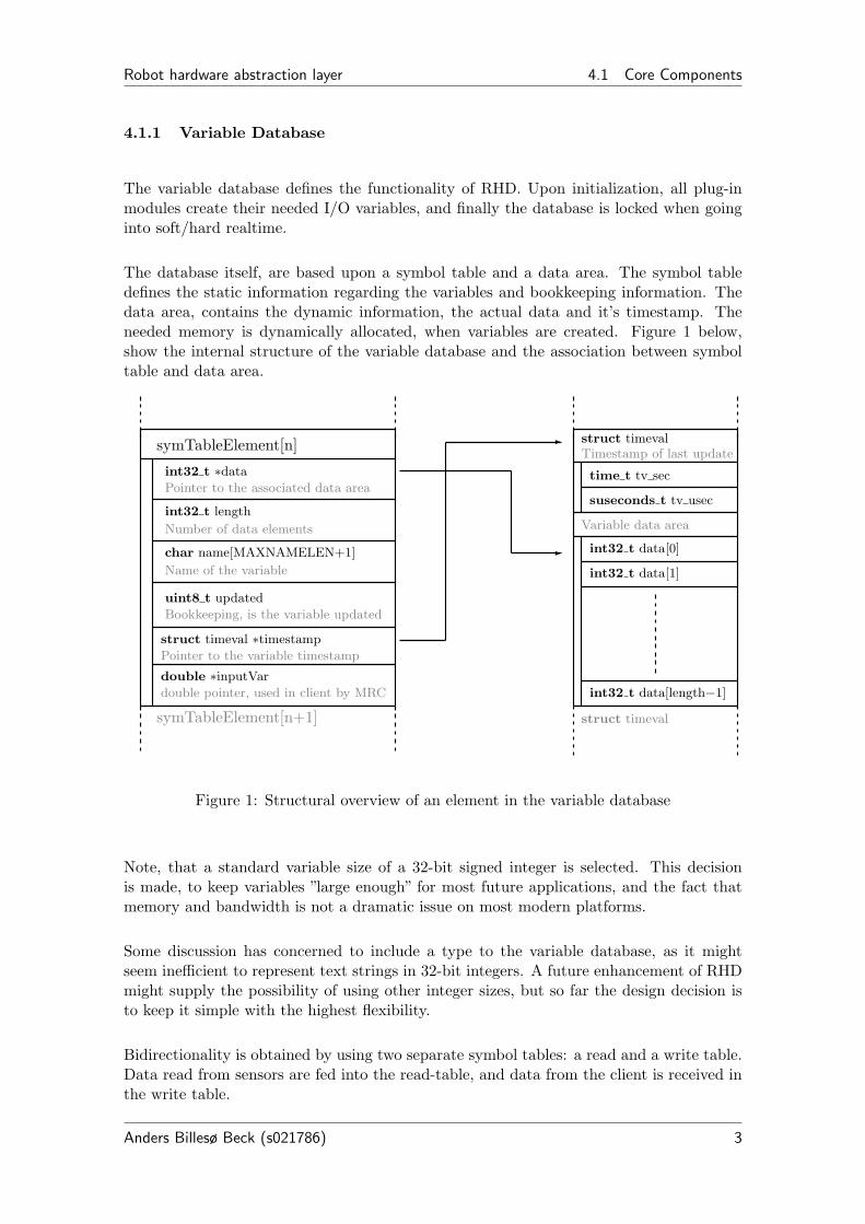
The database itself, are based upon a symbol table and a data area. The symbol tabledefines the static information regarding the variables and bookkeeping information. Thedata area, contains the dynamic information, the actual data and it’s timestamp. Theneeded memory is dynamically allocated, when variables are created. Figure 1 below,show the internal structure of the variable database and the association between symboltable and data area.
symTableElement[n]
int32 t ∗data
Pointer to the associated data area
int32 t length
char name[MAXNAMELEN+1]
uint8 t updated
struct timeval ∗timestamp
double ∗inputVar
symTableElement[n+1]
Number of data elements
Name of the variable
Bookkeeping, is the variable updated
Pointer to the variable timestamp
double pointer, used in client by MRC
struct timevalTimestamp of last update
time t tv sec
suseconds t tv usec
Variable data area
int32 t data[0]
int32 t data[1]
int32 t data[length−1]
struct timeval
-
-
Figure 1: Structural overview of an element in the variable database
Note, that a standard variable size of a 32-bit signed integer is selected. This decisionis made, to keep variables ”large enough” for most future applications, and the fact thatmemory and bandwidth is not a dramatic issue on most modern platforms.
Some discussion has concerned to include a type to the variable database, as it mightseem inefficient to represent text strings in 32-bit integers. A future enhancement of RHDmight supply the possibility of using other integer sizes, but so far the design decision isto keep it simple with the highest flexibility.
Bidirectionality is obtained by using two separate symbol tables: a read and a write table.Data read from sensors are fed into the read-table, and data from the client is received inthe write table.
Anders Billesø Beck (s021786) 3

Robot hardware abstraction layer 4.1 Core Components
Each variable is supplied with a ”updated” flag (see fig 1). The flag is used to implementreactions to updated variables, and to determine what data should be exchanged with theclient.
There might always be a need to know the exact time a variable was updated, so allvariables has a timestamp, that is set, every time a variable is updated. This makesit possible to control timing with a much higher resolution than the fundamental RHDscheduler period.
The API is defined in database.h. This API overview is not intended as a programmingreference, but just to give a feel of, how the database is interfaced.
Variable creation is done by the plug-ins using the function below:
int createVariable (char dir, char len, char ∗name) Add a variable array to the variable pool
The direction, dir, is either the ’r’ og ’w’ character, that determines in which symboltable the variable is created. len assigns the number of elements in the variable array,and the name parameter is a pointer to a text string, containing the desired name of thevariable. CreateVariable returns the id number of the variable, that is used to addressthe data, when performing I/O. When initialization is completed, the database is lockedin soft-realtime-mode, and no further variables can be created.
Interfacing the variables are done through the following functions:
int setVariable (int id , int index, int value) Update a array in the data pool
int setArray (int id , int length, int ∗array) Update a array in the data pool
int setVariable (int id , int index, int value) Get a read variable from the data pool
int getWriteArray (int id, int index, int ∗array) Get a read variable from the data pool
int getReadVariable (int id, int index) Get a read variable from the data pool
int getReadArray (int id, int index, int ∗array) Get a read array from the data pool
int isUpdated (char dir, int id) Check if a variable is updated
Using this simple API, data can be transferred into the read database and out from theread and write database. The id parameter is the variable id, that is returned when thevariable is created, and index is the array-index in the database. Check if variables areupdated is performed through the isUpdated() function.
Other functions, that can be found in the RHD documentation, give the possibility ofinterfacing the symboltables directly, but their use is highly discouraged. The API aboveprovide semaphore and boundary projection, and result in more safe and readable code.
4.1.2 TCP/IP Server
After some consideration around shared memory and direct library interface, it was decidedto use TCP/IP sockets as interface for RHD. Socket based communication provides the best
Anders Billesø Beck (s021786) 4

Robot hardware abstraction layer 4.1 Core Components
independence of architecture and is a closer coupling to the previous server-infrastructure.The main argument for the ”low level” interfaces is speed and efficiency. However, asthe data-throughput of RHD is modest, compared to the capabilities of most modernplatforms, the effort of changing infrastructure and the loss of flexibility, was not worth it.
When designing the database, the primary focus was to create a layout, that is easilysynchronized through a data-interface. That led to the distinction of static data in symboltable, and dynamic data in a data-table. When clients connect to RHD, an initial hand-shake is performed where the symboltables are transmitted. After the handshake, onlydata-table data is exchanged.
Situations can occour, when multiple clients attempt to connect to RHD and control therobot, without realizing the conflict. To avoid this issue, RHD only allow one client toperform write operations, but multiple clients as ”readers”. This is determined by thehandshake.
When designing well-researched elements as communication, it is rarely a good idea tospend too much time inventing new and genius protocols, instead of using well tested anddefined ones. In this case however, it was a strong desire to make the communicationas simple as possible, as close to the database architecture as possible and using as littleoverhead as possible. The resulting protocol is basically a binary transfer of the databasecontents, wrapped in a minimum of control variables.
4.1.2.1 Client / Server handshake
After a client has connected to the RHD server, the client initiates the handshake byrequesting either read or write permission. This check-in is done by sending the 8-bitcharacter ’r’ or ’w’, as shown on figure 2.
Client check-in package: char ’w’ char ’r’or
Figure 2: Client initial check-in in RHD protocol
When the server receive a check-in from a new client, it will respond by transferring thesymboltables from the database. As it is defined in the client structure of RHD, that onlyone client can have write permission, the response from the server. When write access isrequested and write access is available, RHD transmits both the write-symboltable andthe read-symbol table. If only read-access is requested or write access is occupied, RHDrespond by only sending the read-symboltable. Figure below 3 show the data-structure ofthe transmission.
Anders Billesø Beck (s021786) 5

Robot hardware abstraction layer 4.1 Core Components
Read-table are always transmitted, unless too many clients are connected
Server Response:
If write access is requested and allowed write-table is transmitted
char ’w’ int32 t wTableLen ...wSymtableElement[0] wSymtableElement[wTableLen-1]
char ’r’ int32 t rTableLen ... rSymtableElement[rTableLen-1]rSymtableElement[0]
Figure 3: Server symboltable response to client checkin in RHD protocol
The protocol structure is simple. Initially a character identifies the following package as theread- or write-symboltable. Then the number of symboltable elements is transmitted in a32-bit integer. Finally the symboltable elements is transferred in binary format (multi-bytevalues are transmitted in network-byteorder). When both symboltables are transmitted,they are simply transmitted sequentially. If more than the defined number of clients triesto connect, RHD simply closes the connection.
As the symbol table contain a lot of system specific pointers, the client completes thehandshake by allocating the needed memory for the data-section and re-create the data-area pointers. After this procedure, each new RHD client has a complete copy of therelevant variable database structure.
4.1.2.2 Client / Server dynamic data exchange
When a client handshake is completed, RHD only need to transmit the data-area fromthe variable database, to keep the client and server synchronized. RHD is also working asthe primary sheduler for realtime robot control software, such as MRC. This is an extraconcern, when designing the data-exchange.
It is important to notice, that despite my best effort, no network protocol is better thanthe interface it is running on. If soft/(hard) realtime behavior is expected, the only safeway is a local loop-back connection. A wired network interface might also give somewhatpredictable and fast response, but do not expect to maintain reliable or stable operationthrough a wireless network.
The basic consideration of the data exchange protocol is, that latency in the TCP/IPprotocol, is just as much caused by the overhead of small packages than the actual datatransfer. This lead to a protocol, where only one package is sent in each direction in oneserver period.
Figure 4 below, show a typical period, for a RHD server with two connected clients.
Anders Billesø Beck (s021786) 6

Robot hardware abstraction layer 4.1 Core Components
Period n
Period n+1
Motor encoder
Hardware interface
Variabeldatabase
Linesensor
IR sensor
GPS
LinuxT
CP
/IPB
uffer
Client 1 data (Reader = empty package)
Client 0 data (Writer)
Server Data for Client 0
Data for Client 1
Gyroscope
TCP/IP Network interface
Motor speed
Figure 4: Hardware and Client - Server data traffic in one typical RHD period
When a client are done with it’s periodic processing, it transmits a data package, containingall the variables that should be updated to the RHD server. This also counts as a ’ready’sign for the client to RHD. If a client is connected as a reader, this package should be empty,otherwise it is ignored. When the server receive the periodic tick from the scheduler, itstart processing the client data-packages from its TCP/IP buffer and update the incomingvariables in the database. When that is finished, the server transmits a datapackage, onlyto the ’ready’ clients, containing the variables that should be updated in the client.
The package format is identical for both directions and is shown on figure 5
int32 t nVariables
0
1
nVariables-1
int32 t variableId struct timeval int32 t data[0] ... int32 t data[len−1]
int32 t variableId struct timeval int32 t data[0] ... int32 t data[len−1]
int32 t variableId struct timeval int32 t data[0] ... int32 t data[len−1]
Figure 5: RHD Synchronization data package
The package header, is a 32-bit integer, determining how many elements there are in thepayload. If a read-client transmits the datapackage, this integer must be zero (0). Then thepayload follow, starting with the database ID of the variable beeing transmitted, followedby timestamp and data for the variable. It is easy to recognize, that the last part of eachpayload element, is a direct copy of the database data-area for each variable. The onlyprocessing performed on the data, is that all variables are converted between host andnetwork byte-order at each end of the TCP/IP socket.
Anders Billesø Beck (s021786) 7

Robot hardware abstraction layer 4.1 Core Components
Using this, relatively simple protocol, an informative variable database is easily distributedto clients, and variable data is synchronized with a minimum of overhead.
4.1.2.3 XML Configuration of the server
The server XML configuration tag can be seen below:
<s e r v e r><port value=”24902 ”/><c l i e n t s number=”10 ”/>
</ s e r v e r>
The server can be configured to run on any TCP/IP port, but default is 24902. Thisis simply the incremental port from port 24901, used by SMRD. Also the number ofaccepted clients can be configured. The limit is theoretically system memory, but keepyour systems capability in mind, when setting this value. The overhead of having moreread-clients connected is, however, quite small. It is basically set by the resources used bythe TCP/IP stack, to transmit variables to the extra receiver.
4.1.3 Realtime Scheduler
Besides being a networked variable database, RHD is also the main timebase for thelow level robot control applications, such as MRC. The AU robot control platform is instrong growth, and is constantly expanding the range of supported robots. Some of theseplatforms is clearly in the heavy sector, that makes fault tolerance and especially realtimeperformance critical.
Hard realtime performance, is not an issue that is generically supported by the Linuxkernel, as there is no support for kernel preemption. In different projects, as RTAI andRT-Linux, this is solved by patching the kernel with a second scheduler, that allow tasksto work in kernel priority levels and full kernel preemption.
Timing is generally a platform specific issue, is solved in many different ways. X86 plat-forms use a range of timers, such as the old APIC-8259 (Advanced Programmable InterruptController) timing IC to the new HPET (High Precision Event Timer), found on modernplatforms. This makes an universal implementation of a realtime environment difficult.Our RT-implementation of choice is the RTAI (RealTime Application Interface) patches.Despite that RTAI does support a range of architechtures, installation can be cumbersomeor impossible on some platforms.
Linux itself, provide some means of achieving soft realtime performance. RHD would bemost flexible, if it could operate satisfactory on a standard Linux distribution and withenhanced stability using the RTAI sheduler. RHD is capable of exactly that.
Anders Billesø Beck (s021786) 8

Robot hardware abstraction layer 4.1 Core Components
4.1.3.1 Linux Scheduling
To obtain best possible realtime performance in Linux, all realtime threads must be raisedin priority. The default priority of the realtime threads in RHD is one below the maximumallowable in userspace. Furthermore, when initialization is completed, threads must runwith a locked heap, to prevent memory allocation.
The Linux kernel itself is not preemptive, so all scheduling happen in the period of thescheduler, the so-called jiffy. Previously, this frequency was normally set to 100Hz, butseemingly the default of the vanilla kernel is now 250 Hz. This create a period of 4 msand make it impossible to obtain the 10 ms control cycle.
Figure 6 below, show the period times of a Linux Itimer interrupt, set at 10 ms and 40 mstarget periods on the SMR X86 VIA platform and on a Atmel AVR32 Linux evaluationboard.
Figure 6: Scheduler periods with 10 and 40 ms targets on a 250 Hz kernel schedulingfrequency
When trying to time a period, that is not divisible with the scheduler period, the timerwill simply jump between the two closest scheduler ticks and thus create an accurateaverage timing period. This might be resonable, if the timer period is much larger thanthe scheduler period, but for realtime robot control it is highly undesired. If the period isdividable with the scheduler period, performance is very good. Figure 7 show a closeup ofthe second part of figure 6.
Anders Billesø Beck (s021786) 9

Robot hardware abstraction layer 4.1 Core Components
Figure 7: Closeup of samples from 39.8 to 40.2 ms at 250 Hz scheduler frequency and 40ms timer target
Data to figure 7 is logged with a 40 µs interval. If samples from 39.96 - 40.04 ms issummed, it yields a total of 99.90 % of the samples, which is quite good performance.
When compiling the 2.6 Linux kernel, it is possible to set the scheduler frequency for 100,250, 300 and 1000 Hz. To run RHD using the Linux scheduler, the timer loop periodmust be carefully selected as a multipla of the Linux sheduling period. It is stronglyrecommended to use a kernel compiled for 1000 Hz scheduling frequency, for greatestflexibility and resolution.
The RHD scheduler has two implementations of Linux scheduling. The recommended isbased on the Interval timer interrupt, Itimer. The main thread is suspended by a call tothe pause() function, and restarted when the itimer interrupt is caught. Alternatively,an algorithm using the usleep() function is available, but test has shown it to be lessreliable.
SMRD solved the scheduling problem by linking scheduling to the serial port. In eachperiod, a fixed number of bytes was transmitted, and processing is resumed when theserial port buffer was cleared. Waiting for the serial port, placed the thread in I/O-waitcondition, instead of suspending it to the scheduler, making it independent of the schedul-ing period. The principle is good, but RHD should be a flexible framework, independentof hardware elements, so this method was not viable. This performance can be obtainedthrough the RTAI framework.
4.1.3.2 RTAI Scheduling
RTAI supply two ways of implementing realtime applications. Traditional RTAI is only forwriting kernel modules, but a new module LXRT support realtime threads in user space.Kernel space is a thing, that generally should be avoided if at all possible, and as LXRTsupply the needed functionality, this is the implementation of choice.
When a realtime thread is created through LXRT, the LXRT kernel module creates a kernelrealtime service-thread, to handle all realtime requests from userspace. This provides the
Anders Billesø Beck (s021786) 10

Robot hardware abstraction layer 4.1 Core Components
possibility of hard realtime from userspace, but it does not solve the flexibility issue ofbeing able to compile and work with and without RTAI seamlessly.
In RHD this issue is solved by communication through realtime FIFO’s. The schedulerspawn a separate hard realtime thread, who simply perform a periodic wait-loop. Wheneach period expires, it transmit a timestamp through a realtime FIFO channel. The usualmain thread performs a simple read on the FIFO, that make it go into I/O wait state(as done by SMRD). That never release the main thread to the Linux scheduler, but waituntil data is written through the FIFO.
RHD can be compiled on a enviroment supporting RTAI, by supplying the command makeRTAI. When the compile environment is properly setup at the automation servers, this willproperly be changed to make NORTAI, to compile without RTAI, as RTAI scheduling shouldbe used whenever possible.
4.1.3.3 Open loop sheduling
In some rare cases, it might be useful to be able to control the RHD timer period fromone or more plug-ins. The development of RHD has made the previous robot simulatorsuseless, as they emulate SMRD communication. The solution to this, is to write a plug-infor RHD, that uses the Stage simulator1. To be able to control timing from the Stageplugin, the RHD scheduler must be deactivated. To facilitate this request, the freerunningmode was designed.
Using freerunning mode in normal RHD operation could result in very high system loadand invalid data from plug-ins so be careful with this option.
4.1.3.4 XML Configuration of the scheduler
The scheduler is configured by the XML tag below:
<shedu l e r><per iod value=”10000 ”/>< !−−in usec−−><type value=” i t i m e r ”/>< !−−”us l e ep ” , ” i t i m e r ” , ”LXRT” , ” f r e e runn ing ” −−>
</ shedu l e r>
The timing period is defined in µs. Scheduling can be performed using four differentalgorithms, set by the keywords: usleep, itimer, LXRT or RTAI and freerunning. Usingusleep is generally deprecated, but itimer show quite good performance, if the timerperiod is fixed to a multiple of the Linux scheduler period. RTAI can be enabled boththe keywords RTAI or LXRT. If RHD is compiled without RTAI support, it will default toitimer scheduling, if it is set to use RTAI. When using the freerunning, RHD periodswill only be limited by plug-in process time and server operation.
1Part of the Player/Stage project (http://playerstage.sourceforge.net)
Anders Billesø Beck (s021786) 11

Robot hardware abstraction layer 4.2 Plug-in modules
4.2 Plug-in modules
The RHD core framework itself, does not supply possibilities for hardware interaction.Specific drivers are implemented through a plug-in structure.
As drivers are included in operating systems, the principle of drivers in RHD is to ”includeem’ all, use what you need”. In this way, it is avoided that some branches of RHD startdrifting away, as MMRD and HAKOD is specific, but incompatible, implementations ofSMRD.
Plug-ins have the possibility to interface the variable database for client communication,but is responsible for interfacing and parsing data to and from hardware devices.
4.2.1 RHD Plug-in structure
For future developers, the most important issue, is to be able to write new hardwareplug-ins for RHD. The procedure is documented in this section.
Up to version 1.x (current release version), RHD has not implemented hardware drivers asplug-ins, but as C-files that were compiled into RHD. This version also implement a unifieddriver architecture, but calls to the driver is done by explicit function calls in the RHDcore thread. Work has now started on a version 2.0, that will introduce an actual plug-instructure, using Linux dynamically loaded libraries. Despite the plug-in architecture is indevelopment, the interface is tested and final.
4.2.1.1 Plugin library interface
The RHD plug-in loader expect each plug-in to supply three functions:
Initialization The initialization function take a string, that point to the XML configu-ration file as parameter. Initialization is performed, before RHD is switched to softrealtime, so memory allocation is allowed. Most plug-ins use this function to parsethe XML configuration, allocate memory, open I/O ports, and spawn asynchronousreceive threads. If any of these operations fail, the initialization call must returna value < 0. The initialization function is mandatory, before RHD will accept theplug-in.
Periodic function The periodic function is called at each scheduler period. The functiontakes an integer as parameter, that is the number of scheduler ticks, since RHD start.This counter will overflow, at some point. The purpose of the periodic function is toperform write calls and other periodic maintenance. It is important, that executionof this function is as quick as possible, as the all periodic calls are performed from themain thread. No blocking reads or image processing must be done in this call. Write-calls are buffered by the Linux operating system and are allowed. This function isoptional and can be omitted by i.e. read-only plug-ins.
Anders Billesø Beck (s021786) 12

Robot hardware abstraction layer 4.2 Plug-in modules
Shutdown The shutdown function is executed, when RHD catches a kill signal. It canbe used to close ports and end threads properly. The shutdown function is optional.
To enable RHD to load the plug-in properly, the header file must hold the followingfunction declarations:
extern ”C” int initXML (char ∗ xmlf i lename ) ;extern ”C” int p e r i o d i c ( int t i c k ) ;extern ”C” int shutdown (void ) ;
Remember, that the initXML() function is mandatory, the others are optional and will beomitted, if they are not present in the header.
4.2.1.2 Compiling a plug-in
A plug-in should be complied as a Linux shared library. This is done by compiling eachfile, desired to be within the library into .o files, and finally constructing the library. It isimportant, that the library file is named lib[libname].so.[version].
The listing below, show an example of how to compile a shared library on Linux comman-dline:
gcc −fPIC −O2 −c −Wall p lug in . cgcc −fPIC −O2 −c −Wall ext ra . cgcc −shared −Wl,−soname , l ibmyplug in . so . 1 −o l ibmyplug in . so . 1 p lug in . o extra . o − l c
Note, that each .c file is compiled with the -fPIC parameter, that creates PlacementInterdependent Code.
The RHD SVN package contains a plugins folder. Within this folder, all plug-ins havetheir own folder, that contain an individual makefile. The makefile makes the plug-ininto a shared library and moves the resulting binary to the project bin/rhdplugin folder,that holds all rhd plug-ins. When adding a plug-in to RHD, just copy the makefile fromanother plug-in and adjust it to the new plug-in.
Many plug-ins use some shared functions, found in the globalfunc.c file. Plug-ins areloaded into RHD, to acquire access to all functions within RHD, including these functions.globalfunc.c contains functions to perform a secure read/write to a Linux filepointer andto set serial-port parameters.
4.2.1.3 Plug-in XML configuration
The RHD configuration file, normally rhdconfig.xml, has a <plugins> tag section. BeforeRHD is able to load a plug-in, it must have an entry, that follow the template:
<p lug in s basepath=”rhdplug in / ”>< [ p lug in name ] enable=”true ” l i b=” l i b [ p lug in name ] . so . 1 ” c r i t i c a l=”true ”>
<plug in c o n f i g tag 1 . . . /><plug in c o n f i g tag 2 . . . />. . .
Anders Billesø Beck (s021786) 13

Robot hardware abstraction layer 4.2 Plug-in modules
</ [ p lug in name ]></ p lug in s>
The tag identifier should be the plugin name, illustrated by [plugin name] on the listing. Tobe able to easily enable/disable the plugin, it must have an enabled parameter, that setswhether the plug-in will be loaded or not. A lib parameter sets the filename of the plug-in dynamically loadable library. This should normally be named lib[plugin name].so.1,if it is version 1, or .so.2 for version 2. It is not recommended to do too much versionmanagement with compiled plug-ins. The final template parameter is critical. It isan optional parameter, but if it is set to true, RHD will exit if the initialization functionreturns > 0. This is useful, if a sensor critical to the operation of a robot. It will ensure thatthe robot will not operate without this sensor properly initialized. If this tag is omittedor set to false, RHD will run if initialization fails, but not do any further interaction withthe plug-in.
Configuration of the plug-in is done by adding child-tags, between the [plugin name] tags.It is also possible to add further parameters to the [plugin name] tag, but is discouraged.
4.2.2 AuSerial plug-in
One of the main motivations for developing RHD, was that the RS485 serial bus interfacein SMRD was very inflexible. Adding new devices to the bus, or a simple reconfiguration,required a quite large change in both server and client code. A task, tedious and difficultfor the maintainer and almost impossible for students. The AuSerial plug-in is providinga fully XML-configurable interface to the serial protocol, used on the SMR RS-485 bus.
AuSerial is the most complex plug-in for RHD, but also the most flexible. Unlike the otherplug-ins, most of the AuSerial code is used on initialization. The periodic ”running” code,is optimized to be as simple and efficient as possible, thus providing greatest functionality.
4.2.2.1 SMR serial protocol
The serial protocol, used on the SMR sensors, are developed by Per Koch Jensen in histhesis work in 2000. Some insight of the protocol structure is necessary to understandand use the configuration of AuSerial. The protocol is an 8-bit package oriented protocol,based on device ID’s and commands. The package format is shown on figure 8 below:
len CMD data[0] ...ID data[1] data[len−3] data[len−2]
Figure 8: Datapackage in the SMR serial format (8-bit data)
Each package is initiated by a length byte. It determines the number of following bytes,to a maximum of 32 bytes. The following byte is the command and id byte. The leastsignificant hex value is the device id, allowing a adress space of 16 devices. Id 0 is reservedfor broadcast (but currently not used). The most significant hex value is the command,
Anders Billesø Beck (s021786) 14

Robot hardware abstraction layer 4.2 Plug-in modules
also allowing a command space of 16 commands for each device. Command 0xF (16) isreserved for the extended command space, where the actual command is included in thefollowing data byte. This adds 255 commands to the command space. After the id andcommand byte follow 0-31 payload bytes. It is allowed to send a command without anypayload and there are no formal way of organizing data in the payload.
The communication on the SMR bus is full duplex but is working as master-slave. Thecomputer is running the master bus and each sensor is driving the slave bus, when re-sponding to a master request. To avoid collisions, no slave must transmit without beingrequested by the master. Another source of collisions is, if the master requests data froma new slave, before the previous finished its response. This is normally avoided by havingthe master emitting 0’es on the bus, that matches the number of bytes returned from arequest.
The protocol itself, does not provide any means of fail safety. The most common problemis, that it might loose synchronization, and see command or data bytes as length bytes.This could leave a device non operational. This problem is solved by emitting 32 0’es inthe end of each timer period. This would fill the receive buffer of any device that is out ofsync. When sync is recovered, the 0’es would just be a length of zero bytes, and keep thedevice ready for a real package.
4.2.2.2 Configuring busses, devices and commands in XML
AuSerial supplies a fully configurable interface, that allow to several serial ports, eachwith 16 devices and each device with 16 commands. Configuration is placed within the<auserial> XML tag, and is quite lengthy for a full SMR configuration, with all functionsenabled.
The first level of the configuration, is assign a serial port, represented by the <bus> tag.Configuration of a standard serial port is shown below:
<a u s e r i a l enable=”true ” l i b=” l i b a u s e r i a l . so . 1 ” c r i t i c a l=”true ”><bus name=”RS485 ” dev=”/dev/ ttyS0 ” baudrate=”115200 ” h o l d o f f=”6 ”>
[ Bus dev i c e s c o n f i g u r a t i o n here ]</bus><bus . . .
</ a u s e r i a l>
Configuration of the plug-in is explained in section 4.2.1.3, and will not be discussed. Each<bus></bus> set define a serial bus. A bus configured by a name parameter, mostly fordescription. The dev sets the Linux device for the serial port. Communication speed isset by the baudrate parameter. The transmission capacity of the bus is calculated from thescheduler period and transmission speed. For 115.2 kBps, it is 115 byte pr 10 ms.
The holdoff parameter sets how many bytes should be reserved of the bus capacity, for”idle” time. This parameter is created, to ensure that all data traffic is cleared on thebus, in each period. So far RHD only issues a warning, if holdoff is violated, but it isdiscussed if data should be discarded. There is no safe solution to the problem so far, asboth overrunning the bus or discarding possibly critical data is highly unsafe.
Anders Billesø Beck (s021786) 15

Robot hardware abstraction layer 4.2 Plug-in modules
Below the <bus> tag, it is possible to define 16 devices. A device resemble a physical sensoron the bus, and must have an unique id. The XML listing below show the configurationof a SMR motor controller device:
<a u s e r i a l enable=”true ” l i b=” l i b a u s e r i a l . so . 1 ” c r i t i c a l=”true ”><bus name=”RS485 ” dev=”/dev/ ttyS0 ” baudrate=”115200 ” h o l d o f f=”6 ”>
< !−− Le f t motor module −−><dev i ce name=”motorl ” id=”1 ”>
[Command c o n f i g u r a t i o n here ]</ dev i ce><dev i ce . . .
</bus></ a u s e r i a l>
A device is only defined by two parameters, a name, used for description, and id, definingit’s the bus id. The id value must be assigned in HEX values 0-F. The last protocolspecific tag, is the commands, assigned to each device. The standard commands used fora motor controller is shown on the XML listing below:
<a u s e r i a l enable=”true ” l i b=” l i b a u s e r i a l . so . 1 ” c r i t i c a l=”true ”><bus name=”RS485 ” dev=”/dev/ ttyS0 ” baudrate=”115200 ” h o l d o f f=”6 ”>
< !−− Le f t motor module −−><dev i ce name=”motorl ” id=”1 ”>
<cmd name=” r e s e t ” type=”reques t ” cmd=”0 ”/><cmd name=”speed ” type=”reques t ” cmd=”1 ”>
[ Data c o n f i g u r a t i o n here ]</cmd><cmd name=”enclTx ” type=” p o l l ” cmd=”2 ” pad=”5 ” per iod=”1 ” o f f s e t=”0 ”/><cmd name=”enclRx ” type=”reques t ” cmd=”A”>
[ Data c o n f i g u r a t i o n here ]</cmd>
</ dev i ce></bus>
</ a u s e r i a l>
The first defined command, is the reset command. There is no data payload with the resetcommand, and the tag is terminated with />. The <cmd> tag takes a range of parame-ters. The name is used for description. The type parameter accept two values: poll andrequest. Poll commands, is periodically transmitted by RHD but request commands areonly transmitted when associated variables are updated from a RHD client (Configuringdata variables are described in section 4.2.2.3). The device command number is set by thecmd parameter. So far, the extended command space is not supported by the protocol, butmust be done manually, by setting cmd=”F” and assigning the data payload to representthe extended command value. The command parameter must be assigned in HEX values0-F.
Commands, that initiate returning of data from the devices, must have an appropriatepad parameter. This value assigns, how many 0’s that should be written to the bus, whilewaiting for the device to respond. Normally this value is set to the length of the response,but some sensors might have some set-up time, before they answer and need a few bytesof extra padding. Test this carefully, before deciding a value.
Poll commands have the option of two extra parameters: period and offset . They are usedto distribute bus traffic, if poll commands is not needed at every period. A good example is
Anders Billesø Beck (s021786) 16

Robot hardware abstraction layer 4.2 Plug-in modules
the SMR IR sensor modules, where data is updated at 6 Hz. There is no need for samplingthem at 100 Hz. period is used to set how many scheduler periods there is between eachpoll. To avoid all commands being polled at one given period, the parameter offset is usedto move the poll a number of scheduler periods, within it’s own period. offset should beless than period.
The motor module is a good example of, how problems can emerge, when there is no fixedstandard for using a protocol. Poll for encoder values has the command number 0x2, butreturn values in a package with command number 0xA. This is fixed in the example bycreating entries for a poll-command to request values, and a request-command to receivevalues. Messy, but it works.
A plea to all sensor designers, please let sensors return the same command idas the requesting command id.
Using the XML formatting and examples, described in this section, it is possible to createrobots that has any configuration of busses and devices, as long as they follow the SMRserial protocol. Adding an extra linesensor or creating a robot with 10 motor controllers,is just a matter of configuring the sensors with the right id’s and writing the AuSerialconfiguration. Linking the commands to RHD variable data is discussed in the followingsection
4.2.2.3 Associating database variables to AuSerial commands
When a sensor structure is defined in the AuSerial configuration, the real challenge is tomap payload data to RHD database variables. The SMR serial protocol is 8-bit oriented,but sensors use a wide range of payload encondings and representing data in 1-bit, 8-bit,10-bit and 16-bit formats.
To allow full support of existing sensor devices, and allow full flexibility of the SMR serialprotocol, it was necessary to create a method to map each bit of variable to bus data andback from bus data to variable data.
The principle is, that every command can write data to the serial bus, and read data thatis returned. This can be directly linked to a number of RHD database read and writevariables.
As the RHD variable database is array oriented, it is possible to create arrays and variables.A variable is basically an array with one element. For the sake of simpliticy, the firstexample will show the configuration of a variable.
Variable mapping (single element array)
This XML listing show the variable configuration of the return data from a motor controller(without the preceeding tags):<cmd type=”reques t ” name=”enclRx ” cmd=”A”>
<v a r i a b l e name=”enc l ” d i r=”r ” byte0=”1 ” byte1=”0 ”/><v a r i a b l e name=”pwml” d i r=”r ” byte0=”3 ”/>
</cmd>
Anders Billesø Beck (s021786) 17

Robot hardware abstraction layer 4.2 Plug-in modules
In the example ”enclRx” create two variables, ”encl” and ”pwml”. Both variables have theparameter dir set to ”r”, meaning that they are read-variables. The interesting part, isthe byte-mapping. The parameter byte0..byte4, assign the 4 bytes in the 32-bit databasevariable to the 0-31 byte of serial bus payload data. Figure 9 show how the payload bytesare mapped to the variables in the enclRx example.
encl
pwmlEncoder data package
Variables5 0xA1 0 1 2 3
3 012
3 0128162432Bit
byte0="1"byte1="0"
Payload bytes
byte0="1"
Figure 9: Mapping of serial bus payload bytes to RHD variable bytes for motor controllerencoder values
Array mapping
Often multiple data values are associated, such as the 8 readings of the SMR linesensors.To allow easiest access to these values, the RHD variable database is array-oriented. Inthe same way as the encoder example before, serial payload data can also be mapped toarrays. Below is an example of how to map the 8 linesensor mesurements to an 8-elementarray
<cmd type=” p o l l ” name=”va lues ” cmd=”1 ” pad=”10 ”><array name=” l i n e s e n s o r ” d i r=”r ”>
<element byte0=”0 ”/><element byte0=”1 ”/><element byte0=”2 ”/><element byte0=”3 ”/><element byte0=”4 ”/><element byte0=”5 ”/><element byte0=”6 ”/><element byte0=”7 ”/>
</ array></cmd>
The plugin automatically create an database variable with an array size, that matches thenumber of element tags. Each array element has byte0 mapped to 8 consecutive bytes ofthe payload, as illustrated on figure 10.
Anders Billesø Beck (s021786) 18

Robot hardware abstraction layer 4.2 Plug-in modules
linesensor[0]
Linesensor data package Array elements
9 0x17 0 1 2 3
3 012
3 0128162432Bit
byte0="1"
byte0="0"
Payload bytesbyte0="2"
4 5 6 7
3 012
3 012
3 012
3 012
3 012
3 012
byte0="3"
byte0="4"
byte0="5"
byte0="6"
byte0="7"
linesensor[1]
linesensor[2]
linesensor[3]
linesensor[5]
linesensor[4]
linesensor[6]
linesensor[7]
Figure 10: Mapping of several array elements to a linesensor serial bus package
Bit-mapping
The final mapping method is individual bit mapping. As the transfer capacity of the serialbus is limited, variable data is often packed bitwise into the payload. A good example ofthis, is the SMR power supply module, that has 5 10-bit ADC mesurements and 6 1-bitboolean values mapped into 6 payload bytes. Figure 11 illustrate, how the vaulues ofdifferent resolution are packed into the 8-bit serial format.
f e d c b a A A B BCCDDEE A AA AA AA A B BB BB BB B CCCCCCCC DDDDDDDD EEE EE EE E
1-bit digital 2 MSB of 10-bit analog 8 LSB of 10-bit analog
Figure 11: Payload package from power module, boolean digital values a-f and 10-bitanalog measurements A-E are packaged into 8-bit blocks
To resolve payloads like this, into variables, it is nesseary to be able to map each individualbit of the payload into a specific bit of the database variable. Bit mapping is done by theparameter b0 − b31, that assigns bit 0 to 31 of the database variable to the bit assigned inthe parameter value. The syntax for the bit-map parameter is bN=”bit,byte”, where bit isthe addressed payload bit and byte is the addressed payload byte. An example of the fullmapping of the power module payload is shown in the XML listing below:
<cmd type=” p o l l ” name=”s t a t u s ” cmd=”1 ” pad=”10 ”><array name=” d i g i t a l ” d i r=”r ”>
<element b0=”2 ,0 ”/> < !−− a −−><element b0=”3 ,0 ”/> < !−− b −−><element b0=”4 ,0 ”/> < !−− c −−><element b0=”5 ,0 ”/> < !−− d −−><element b0=”6 ,0 ”/> < !−− e −−><element b0=”7 ,0 ”/> < !−− f −−>
</ array><array name=”analog ” d i r=”r ”>
<element byte0=”2 ” b8=”0 ,0 ” b9=”1 ,0 ”/> < !−− A −−><element byte0=”3 ” b8=”6 ,1 ” b9=”7 ,1 ”/> < !−− B −−><element byte0=”4 ” b8=”4 ,1 ” b9=”5 ,1 ”/> < !−− C −−>
Anders Billesø Beck (s021786) 19
Robot hardware abstraction layer 4.2 Plug-in modules
<element byte0=”5 ” b8=”2 ,1 ” b9=”3 ,1 ”/> < !−− D −−><element byte0=”6 ” b8=”0 ,1 ” b9=”1 ,1 ”/> < !−− E −−>
</ array></cmd>
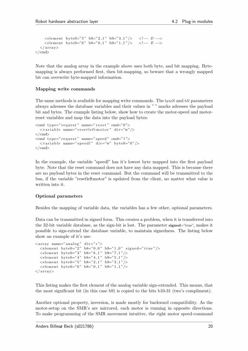
Note that the analog array in the example above uses both byte, and bit mapping. Byte-mapping is always performed first, then bit-mapping, so beware that a wrongly mappedbit can overwrite byte-mapped information.
Mapping write commands
The same methods is avaliable for mapping write commands. The byteN and bN parametersalways adresses the database variables and their values in ” ” marks adresses the payloadbit and bytes. The example listing below, show how to create the motor-speed and motor-reset variables and map the data into the payload bytes:
<cmd type=”reques t ” name=” r e s e t ” cmd=”0 ”><v a r i a b l e name=” r e s e t l e f t m o t o r ” d i r=”w”/>
</cmd><cmd type=”reques t ” name=”speed ” cmd=”1 ”>
<v a r i a b l e name=”speed l ” d i r=”w” byte0=”0 ”/></cmd>
In the example, the variable ”speedl” has it’s lowest byte mapped into the first payloadbyte. Note that the reset command does not have any data mapped. This is because thereare no payload bytes in the reset command. But the command will be transmitted to thebus, if the variable ”resetleftmotor” is updated from the client, no matter what value iswritten into it.
Optional parameters
Besides the mapping of variable data, the variables has a few other, optional parameters.
Data can be transmitted in signed form. This creates a problem, when it is transferred intothe 32-bit variable database, as the sign-bit is lost. The parameter signed=”true”, makes itpossible to sign-extend the database variable, to maintain signedness. The listing belowshow an example of it’s use:
<array name=”analog ” d i r=”r ”><element byte0=”2 ” b8=”0 ,0 ” b9=”1 ,0 ” s igned=”true ”/><element byte0=”3 ” b8=”6 ,1 ” b9=”7 ,1 ”/><element byte0=”4 ” b8=”4 ,1 ” b9=”5 ,1 ”/><element byte0=”5 ” b8=”2 ,1 ” b9=”3 ,1 ”/><element byte0=”6 ” b8=”0 ,1 ” b9=”1 ,1 ”/>
</ array>
This listing makes the first element of the analog variable sign-extended. This means, thatthe most significant bit (in this case b9) is copied to the bits b10-31 (two’s compliment).
Another optional property, inversion, is made mostly for backward compatibility. As themotor-setup on the SMR’s are mirrored, each motor is running in opposite directions.To make programming of the SMR movement intuitive, the right motor speed-command
Anders Billesø Beck (s021786) 20

Robot hardware abstraction layer 4.2 Plug-in modules
and the resulting encoder readings are inverted in the old SMRD enviroment. This givesthe illusion that both motors are running in the same direction. To give this function-ality, AuSerial has the invert=”true” parameter. The example listing below, show the fullconfiguration of the right motor controller:< !−− Right motor module −−><dev i ce name=”motorr ” id=”2 ”>
<cmd type=”reques t ” name=” r e s e t ” cmd=”0 ”><v a r i a b l e name=”re s e t r i gh tmoto r ” d i r=”w”/>
</cmd><cmd type=”reques t ” name=”speed ” cmd=”1 ”>
<v a r i a b l e name=”speedr ” d i r=”w” byte0=”0 ” i n v e r t=”true ”/></cmd><cmd type=” p o l l ” name=”encrTx ” cmd=”2 ” pad=”5 ”/><cmd type=”reques t ” name=”encrRx ” cmd=”A”>
<v a r i a b l e name=”encr ” d i r=”r ” byte0=”1 ” byte1=”0 ” i n v e r t=”true ”/><v a r i a b l e name=”pwmr” d i r=”r ” byte0=”3 ” i n v e r t=”true ”/>
</cmd></ dev i ce>
Note that all values are inverted on the motor.
4.2.2.4 Final notes on the AuSerial plug-in
AuSerial is by far the most advanced plug-in written for RHD so far. The clear vision wasto create a fully configurable interface, that can provide full support for existing and newdevices on the SMR serial bus. I believe that it has been successfull.
It has been highly focussed, that most advanced code is placed in the initialization phase,and simplifying the run-time code. Actual run-time code is actually only around 300 linesof the 1000 lines plug-in.
When the configuration of AuSerial is understood, it is not overwhelmingly difficult. It is,however intended that it should be using standard configuration files, and only changedby ”SMR Experts” for new hardware or special projects as Eurobot.
One functional thing is missing. It is not possible to execute the shutdown function, fromstatus of a variable. In SMRD, the Linux shutdown is executed when bit a (see figure11) from the power-module is set. The vision of a solution, is a possibility to map anysystem command to the status of a variable. This will also provide a useful functionality toexecute system functions, such as audio playback or screen output from external sensors.
4.2.3 GPS plug-in
The first task for the RHD system, was a full implementation on the automated HAKOtractor at KU Life. The original hardware daemon for this purpose, HAKOD, was writtenby Asbjørn Mejnertsen and Anders Reeske Nielsen in 2006. It provided interface for thespecific hardware modules on the HAKO tractor, but wrapped in the SMRD protocol.That made it possible to re-use most interface code and easily create RHD plug-ins forthe hardware.
Anders Billesø Beck (s021786) 21

Robot hardware abstraction layer 4.2 Plug-in modules
The GPS plug-in was created in combination of using the code from HAKOD and theGPS server by Lars Mogensen and Christian Andersen, with a slight re-write of the serialinterface. Using these code-bits, the GPS module provides support for standard NMEAGPS and the RTK GPS, used on the HAKO tractor.
When a standard NMEA GPS is used, koordinates are converted from Lat-Lon to UTM,using a default UTM Zone, assigned in the configuration file. It is possible to change thezone using a write-variable.
The configuration of the plug-in is done on in the following piece XML<gps enable=”true ” l i b=” l i b g p s . so . 1 ” c r i t i c a l=”true ”>
< s e r i a l port=”/dev/rfcomm0 ” baudrate=”4800 ”/><utmzone value=”32 ”/>< !−− Defau l t UTM Zone −−>
</gps>
The configuration give the possibility of setting the serial port, baudrate and default UTMzone. In this example, the port is configured a bluetooth serial NMEA GPS.
The GPS plug-in creates the following database variables:
Variable Dir Variable contents Descriptiongpstime r [hour][min][sec][ms] Time of day in millisecons resolutiongpsdate r [dd][mm][yyyy] Date in day, month and yeargpstimeofday r [sec][µsec] Linux timeofday in second and µsecondsgpsnorthing r [m][µm] UTM Northing coordinategpseasting r [m][µm] UTM Easting coordinategpslattitude r [deg][µdeg] Lattitude coordinate (NMEA GPS only)gpslongitude r [deg][µdeg] Longitude coordinate (NMEA GPS only)gpsquality r [quality] Quality of GPS fixgpsfixvalid r [0 / 1] Binary value of valid fixgpssatused r [sats] Number of sattelites used in the fixgpsdop r [dop][1/10 of dop] Horizontal dillution of precisiongpsaltitude r [m] GPS Altitudegpsheigth r [m] GPS Heigthgpsheading r [deg][mdeg] GPS Headinggpsspeed r [m/s][mm/s] Speed over groundgpsegnos r [egnos] Binary EGNOS fix (Unused)gpsllfixes r [fixes] No. of fixes with lat-long (NMEA GPS)gpsutmfixes r [fixes] No. of fixes with UTM (RTK GPS)gpsutmzone r [zone] UTM Zone for lat-long to UTM conversiongpssetutmzone w [zone] Write variable to set UTM zone
Table 1: Database variables created by the GPS plug-in
4.2.4 Crossbow gyro plug-in
Another device used on the HAKO tractor is the Crossbow IMU400. It is a full fledged3-axis IMU, providing gyro rates and accelleration on all three axis. As it is based on
Anders Billesø Beck (s021786) 22

Robot hardware abstraction layer 4.2 Plug-in modules
MEMS technology, it does have a small drift on gyro mesurements, but provide prettydecent performance. The price-tag is arround 15.000 dkk.
The RHD driver is mainly from Asbjørn Mejnertsen and Anders Reeske Nielsen’s HAKOD,but the Crossbow initialization has been completely rewritten and a lot of busy-wait loopshas been removed. The Crossbow unit available on the tractor does have some freezeissues with it’s firmware, that can make the initialization fail. It is highly recomended touse the critical =”true” parameter, if the gyro operation is needed. This way, RHD will notoperate, if the crossbow is not initialized properly.
XML configuration of the Crossbow plug-in is fairly simple:
<crossbow enable=” f a l s e ” l i b=”l ibc ro s sbow . so . 1 ” c r i t i c a l=”true ”>< s e r i a l port=”/dev/ttyUSB1 ” />
</ crossbow>
When initialized properly, the Crossbow plug-in creates the following variables:
Variable Dir Variable contents Descriptionxbowroll r [roll] IMU rate of rollxbowpitch r [pitch] IMU rate of pitchxbowyaw r [yaw] IMU rate of yawxbowx r [accl X] IMU accelleration in X directionxbowy r [accl Y] IMU accelleration in Y directionxbowz r [accl Z] IMU accelleration in Z directionxbowtemp r [temp] IMU Temperaturexbowtime r [time] IMU Time
Table 2: Database variables created by the Crossbow plug-in
Further description of the data, can be found in the IMU400 datasheet.
4.2.5 Fibre Optic Gyro plug-in
When working on their project of ”Fault tolerant navigation for Mobile Robots”, PeterTjell and Søren Hansen received a Fibre Optic Gyro (FOG), that was just lying around atKVL (KU Life). It was promptly interfaced to RHD and intensively used on the HAKOtractor during their thesis project.
The FOG uses two RS-422 serial busses. One for setup and one for data. Using a clevercable, it is possible to run the FOG, using only one RS-422 port. This works if the TXpair is connected to the setup connector input and the RX pair is connected to the dataconnector output. This plug-in is written, so that both using two RS-422 ports or just oneRS-422 port is possible. Setup is done at 9600 baud and data communication is done at57600 baud.
The XML configuration is seen in the listing below:
Anders Billesø Beck (s021786) 23

Robot hardware abstraction layer 4.2 Plug-in modules
<f ogyro enable=”true ” l i b=” l i b f o g y r o . so . 1 ” c r i t i c a l=”true ” ><d a t a s e r i a l port=”/dev/ttyUSB0 ” baudrate=”57600 ”/><c o n f i g s e r i a l port=”/dev/ttyUSB0 ” baudrate=”9600 ”/><sampletime value=”10 ”/>< !−− t ime pr sample in ms −−>
</ fogyro>
In the configuration, it is possible to assign serial ports for both configuration and data.It is also possible to set the time pr. sample, performed by the gyro. See datasheet forfurther details.
The FOGyro plug-in creates the following database variables:
Variable Dir Variable contents Descriptionfogphx r [φx] φX anglefogphy r [φy] φY anglefogphdz r [φ∆z] φ∆Z rate. (aka. Yaw rate)fogtempb r [tempb] Temperature mesurementfogtempe r [tempe] Temperature mesurementfogfailstatus r [status] Failure status bitsfoggyrostatus r [status] Gyro status bits
Table 3: Database variables created by the FOGyro plug-in
See datasheet for further information regarding the variables
4.2.6 SMRDSerial plug-in
AuSerial was the last developed module for RHD. To have a stabile plug-in for testing, themain code of SMRD was ported into a RHD plug-in, named SMRDSerial. That made itpossible to control all functions of the SMR, with a very short plug-in development timeand through verified software.
This plug-in was essential to the development and debugging of RHD and is still in use for”long time verification” of the operation. When AuSerial is properly tested and configured,SMRDSerial will be declared depreciated.
Configuration of SMRDSerial is done through the following piece of XML:
< !−− SMRD Se r i a l bus module −−><smrd enable=”true ” l i b=” l i b s m r d s e r i a l . so . 1 ” c r i t i c a l=”true ”>
<s e r i a l 1 port=”/dev/ ttyS0 ” baudrate=”115200 ”/><s e r i a l 2 port=”/dev/ ttyS1 ” baudrate=”115200 ”/>
</smrd>
It is possible to configure both serial ports, for RS-485 (serial1) and optional RS-232 forthe RS-232 linesensor.
SMRDSerial creates the following database variables:
Anders Billesø Beck (s021786) 24

Robot hardware abstraction layer 4.3 librhd Client library
Variable Dir Variable contents Descriptionencl r [enc] Left encoder valueencr r [enc] Right encoder valuelinesensor r [ls1][ls2]...[ls8] 8 Linesensor mesurementsirsensor r [ir1][ir2]...[ir6] 6 Ir sensor mesurementsgyro r [pos1][pos2][pos3] Uncompensated position of the 3 gyrosgyrotemp r [temp1][temp2][temp3] Gyro temperaturesspeedl w [speed] Speed command for left motorspeedr w [speed] Speed command for right motorresetmotorl w [reset] Reset command for left motorresetmotorr w [reset] Reset command for right motorsteeringangleref w [angle] Steering angle for the Ackerman SMR
Table 4: Database variables created by the SMRDSerial plug-in
4.2.7 Hako CAN-bus plug-in
The HAKO tractor is operated through a CAN-bus interface to the ESX ECU (EngineControl Unit), that is running a custom control code. Asbjørn Mejnertsen and AndersReeske Nielsen wrote a piece of interface code into HAKOD, that has been the foundationfor this plug-in.
HAKOD was never compatible with the Slackware Linux distribution, that is used on theRSE platform, as it used a Debian CAN-bus driver. Through quite some effort from NilsA. Andersen and Ole Ravn, it was possible to port the HAKOD code to use the SlackwareCAN-bus driver and a plug-in was developed, that is able to control the HAKO tractorECU.
As this plug-in is developed by Nils A. Andersen and not yet re-integrated into the devel-opment branch of RHD, and will not be described further in this report.
4.3 librhd Client library
For easy client development, RHD is supplied with a client library. The library providesfunctions to connect and synchronize to RHD servers, maintaining of the local variabledatabase and I/O functions to use database data.
Despite that RHD is a real-time server, a client does not need to fullfill any real-timerequirements. RHD will operate fine, servicing a real-time client while also transmittingdata to non real-time ”spectator” clients.
4.3.1 Communicating with the RHD server
The communication API is controlled by three functions:
Anders Billesø Beck (s021786) 25

Robot hardware abstraction layer 4.3 librhd Client library
char rhdConnect (char rw , char ∗host , int port ) ;char rhdSync (void ) ;char rhdDisconnect (void ) ;
rhdConnect() establishes connection to a RHD server. It takes three parameters:
rw Set the desired access level. ’w’ requests write access and ’r’ requests read access torhd
host Char string holding host name for the RHD server
port Integer holding the TCP port, that RHD is running on
If connection fails, rhdConnect() returns -1, but if connection is successful, it returnseither ’w’ or ’r’, depending on what access level was granted from the RHD server. If onewrite client already is connected, rhdConnect() returns ’r’ and is only able to receive datafrom RHD.
rhdSync() is the periodic function, that transmits write variables to the RHD server (ifconnected as write-client), and waits for read variables from the server. When this functionis called, the thread will block, until a RHD server period is expired and data is exchanged.This is used to keep real-time synchronization between RHD server and client.
rhdDisconnect() closes the connection to the RHD server and frees memory allocatedfor the database.
4.3.2 Communicating with the variable database
Getting variable data in and out of the synchronized variable database can be done in twoways. The most efficient way is to access the variable symbol table directly. This methodis also the most unsafe, and should only be used if performance is critical, as in MRC.
The API for this access method is
symTableElement∗ getSymbolTable (char rw ) ;int getSymbolTableSize (char rw ) ;
Using the function getSymbolTable() will return a pointer to the symbol table array.Iterating through this array, makes direct data access possible. getSymbolTableSize()sets the limits for iterating, when searching for variables. The symbol table structure isdescribed in section 4.1.1 on page 3. Be very careful, when using this method, as there areno protection against writing outside the symbol table arrays or data-areas. Timestampmust also be updated manually.
The preferred method is to use the dedicated I/O API. The functions is described below
Anders Billesø Beck (s021786) 26

Robot hardware abstraction layer 4.3 librhd Client library
int getReadValue ( int id , int index ) ; //Get va lue from read−databaseint ∗ getReadArray ( int id ) ; //Get array po in t e r from read−databaseint getWriteValue ( int id , int index ) ; //Get va lue from wri te−databaseint ∗ getWriteArray ( int id ) ; //Get array po in t e r from wri te−databaseint setWriteValue ( int id , int index , int value ) ; //Write va lue to wri te−databaseint setWriteArray ( int id , int l ength , int∗ ar raypt r ) ; //Write array to wri te−databasechar isUpdated (char rw , int id ) ; // I s the r/w−database va lue updatedchar ∗ getVarName (char rw , int id ) ; //Get po in t e r to v a r i a b l e nameint getVarLength (char rw , int id ) ; //Get the l e n g t h o f v a r i a b l e data−array
This API will allow full access to the read and write databases, but also provide protectionfor writing outside desired memory areas and perform all required book-keeping. The APIis still in development, and might be subject for change. Always check the rhd.h headerand Doxygen documentation for the most recent API. Operations of the API is almostidentical to the variable database API described in section 4.1.1 on page 3.
Anders Billesø Beck (s021786) 27

Robot hardware abstraction layer 5 Testing on various platforms
5 Testing on various platforms
Robot systems can run on a large range of embedded platforms. To ensure full versatility,RHD has been programmed using full endian-safe code.
To test the flexibility of the system, RHD and MRCs predecessor SMRDEMO was compiledand tested on two non-x86 platforms. T The requirement was that the platform supportedLinux and the GCC compliler. The systems used for test were
• Atmel ATNGW100 development board with a 130 MHz AVR32 Application proces-sor and running a custom Linux Buildroot on kernel 2.6.19
• Fujitzu-Siemens Loox 720 PDA with a 520 MHz Intel XScale processor and DebianLinux 2.6.21
Figure 12: Atmel ATNGW100 developmentboard
Figure 13: Fujitzu-Siemens Loox 720 PDA
The AVR32 platform was supported by a large toolchain from Atmel, that made it possibleto cross-compile both RHD and MRC into AVR32-binary code.
The Intel XScale is supported by the Debian distribution, and the driver adjustment wasdone through an Loox720 open-source project. As the XScale is supported by Debian, allGNU tools are available for download through the Debian package-manager and compila-tion was done on the Loox720 itself.
Both software elements was tested individually. The functional test of SMRDEMO, weredone using SMRD as hardware abstraction layer, instead of RHD, as MRC was not fullydeveloped when the tests were performed. RHD was only tested using the demo clientapplication.
The results of the is illustrated in table 5 below
Anders Billesø Beck (s021786) 28

Robot hardware abstraction layer 6 Further development
RHD SMRDEMO+SMRDCompile Test Compile Test
AVR32 Works Works Works WorksIntel XScale Works Works Works Works
Table 5: Test results of compiling and testing RHD and SMRDEMO on AVR32 and XScalearchitecture
As seen in table 5, both RHD, and (SMRDEMO + SMRD) worked on both platforms,without corrections in the code. Only when cross-compiling to the AVR32 platform, itwas necessary to correct makefiles, to use the cross-compiling toolchain.
The conclusion of this test, is that the robot-control platform has now reached a level,where it allows a very high level of flexibility both in choice of robot hardware and computerplatform.
6 Further development
RHD has now moved to the maturing development phase. The plug-in structure is notyet implemented, and some minor corrections are still in due process.
The program is now in care of the Robot Systems Engineering (RSE) group and the newestprogram version can be found in the RSE SVN repository. Note that SVN developmentshould follow the guidelines for SVN2, using trunk, branches and tags. The most recentstable development version is always found within the trunk section.
Updated documentation of RHD is always found in the RSE wiki3, that will provide theinformation from this report and any new development information.
2See http://svnbook.red-bean.com/3RHD can be found at: http://timmy.elektro.dtu.dk/rse/wiki/index.php/RHD
Anders Billesø Beck (s021786) 29
Robot hardware abstraction layer 7 Conclusion
7 Conclusion
The aim of this project, was to review the AU robot control architecture, to identifyand redesign any un-addressed leftovers from single-platform dawn of the architecture.The largest structural problem was quickly identified as the various hardware abstractionlayers, used on the robots.
Through this project, a new, flexible hardware abstraction layer, the Robot HardwareDaemon (RHD), was implemented. RHD provides a fully XML configurable interface, andprovides all the basic functionality of realtime scheduling and client-server communication.Hardware interaction is provided through a plug-in interface, to provide maximal flexibilityand expansibility.
To provide proof-of-concept, plug-ins was programmed for the SMR platform and theHAKO platform. Both platforms runs exactly the same software, just using differentconfiguration and plug-ins.
One drawback of changing to a different HAL, was that the robot simulators designedat AU, now become inoperational. This problem is already now in the process of beingsolved, by designing a plug-in for RHD that loads the simulator Stage, provided with thePlayer/Stage project. It had been a desire for a long time, to utilize Stage and possiblythe 3D simulator Gazebo and that has been possible using RHD.
RHD must be considered an overall success. The core has proven itself flexible, stable andproviding new functionality throughout the control system, such as dynamic variables.The plug-in architecture makes it simple to change robot architectures and add new hard-ware. In close future, another robot will join the family of RHD supported robots, theiRobot ATRV-Jr and hopefully many more will follow soon.
Anders Billesø BeckAutomation, DTU Electrical EngineeringSeptember 8, 2008
Anders Billesø Beck (s021786) 30

Robot hardware abstraction layer A Example XML Configuration files
A Example XML Configuration files
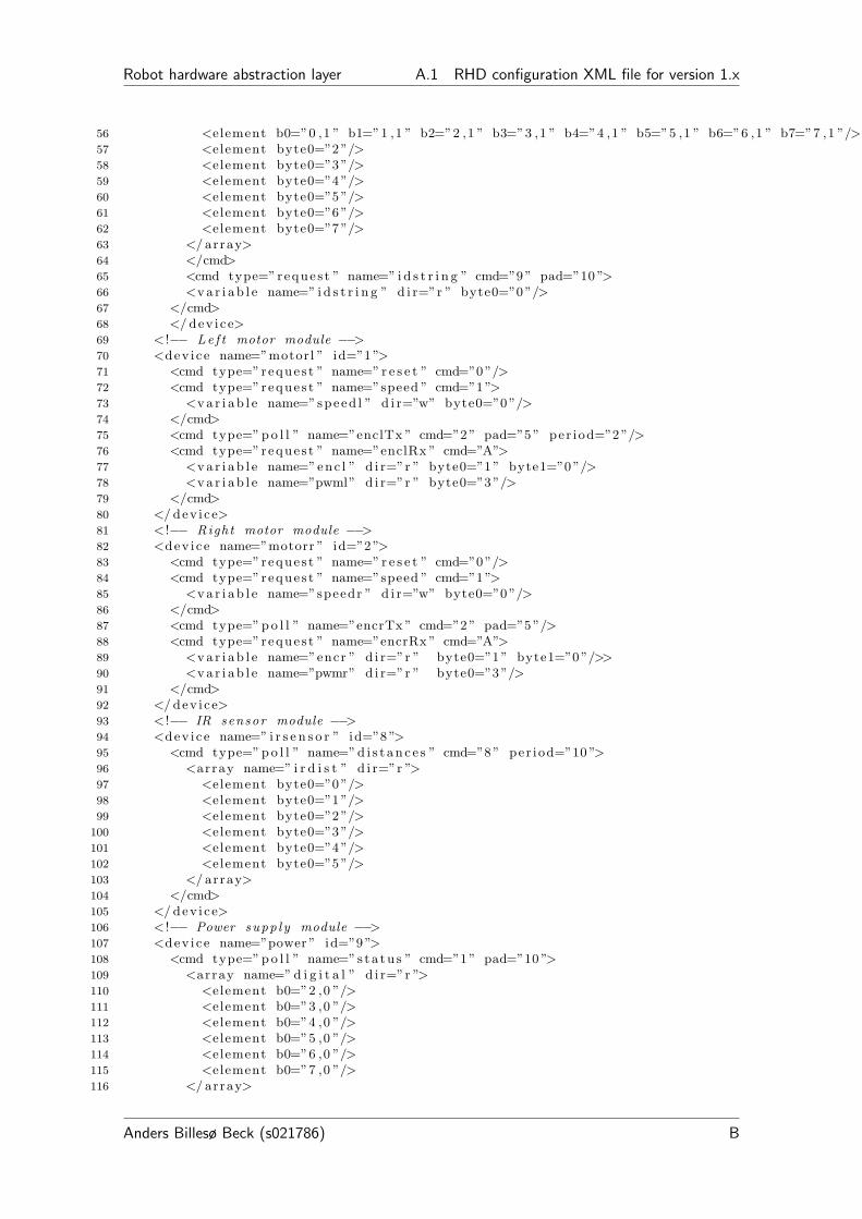
A.1 RHD configuration XML file for version 1.x
1 <?xml version=”1 .0 ” ?>2 < !−−3 Conf i gura t ion f i l e f o r4 Robot Hardware Daemon5
6 See something e l s e f o r c on f i g u r a t i on d e s c r i p t i o n7
8 $ I d : rhdcon f i g .xml 144 2008−05−18 22 :29:25Z andersbeck $9 −−>
10 <rhd>11 < !−− ∗∗∗ Core Components Conf i gura t ion ∗∗∗ −−>12 < !−− Shedu ler c on f i g u ra t i on −−>13 <shedu l e r>14 <per iod value=”10000 ”/>< !−−in usec−−>15 <type value=” i t i m e r ”/>< !−−”us l e ep ” , ” i t i m e r ” , ”LXRT” −−>16 < r t a i i n i t cmd=”. / i n i t r t a i . sh ”/>< !−− Sc r i p t to i n i t i a l i z e RTAI −−>17 </ shedu l e r>18 < !−− Server con f i g u ra t i on −−>19 <s e r v e r>20 <port value=”24902 ”/>21 <c l i e n t s number=”10 ”/>22 </ s e r v e r>23 < !−− ∗∗∗ Modules Conf i gura t ion ∗∗∗ −−>24 < !−− SMRD Se r i a l bus module −−>25 <smrd enable=”true ”>26 <s e r i a l 1 port=”/dev/ ttyS0 ” baudrate=”115200 ”/>27 <s e r i a l 2 port=”/dev/ ttyS1 ” baudrate=”115200 ”/>28 </smrd>29 < !−− HAKO Tractor CAN−Bus module −−>30 <hakocan enable=” f a l s e ”>31 <cont ro l can port=”/dev/can1 ”/>32 </hakocan>33 < !−− Crossbow IMU Conf igura t ion −−>34 <crossbow enable=” f a l s e ”>35 < s e r i a l port=”/dev/ttyUSB1 ”/>36 </ crossbow>37 < !−− Fibre Optic Gyro module −−>38 <f ogyro enable=” f a l s e ”>39 <d a t a s e r i a l port=”/dev/ttyUSB0 ” baudrate=”57600 ”/>40 <c o n f i g s e r i a l port=”/dev/ttyUSB0 ” baudrate=”9600 ”/>41 <sampletime value=”10 ”/>< !−− t ime pr sample in ms −−>42 </ fogyro>43 < !−− S e r i a l GPS module −−>44 <gps enable=” f a l s e ”>45 < s e r i a l port=”/dev/rfcomm0 ” baudrate=”4800 ”/>46 <utmzone value=”32 ”/>< !−− Defau l t UTM Zone −−>47 </gps>48 < !−− Automation s e r i a l bus d r i v e r −−>49 <a u s e r i a l enable=” f a l s e ”>50 <bus name=”RS485 ” dev=”/dev/ ttyS0 ” baudrate=”115200 ” h o l d o f f=”6 ”>51 < !−− Linesensor module −−>52 <dev i ce name=” l i n e s e n s o r ” id=”7 ”>53 <cmd type=” p o l l ” name=”va lues ” cmd=”1 ” pad=”10 ”>54 <array name=” l i n e s e n s o r ” d i r=”r ”>55 <element byte0=”0 ”/>
Anders Billesø Beck (s021786) A
Robot hardware abstraction layer A.1 RHD configuration XML file for version 1.x
56 <element b0=”0 ,1 ” b1=”1 ,1 ” b2=”2 ,1 ” b3=”3 ,1 ” b4=”4 ,1 ” b5=”5 ,1 ” b6=”6 ,1 ” b7=”7 ,1 ”/>57 <element byte0=”2 ”/>58 <element byte0=”3 ”/>59 <element byte0=”4 ”/>60 <element byte0=”5 ”/>61 <element byte0=”6 ”/>62 <element byte0=”7 ”/>63 </ array>64 </cmd>65 <cmd type=”reques t ” name=” i d s t r i n g ” cmd=”9 ” pad=”10 ”>66 <v a r i a b l e name=” i d s t r i n g ” d i r=”r ” byte0=”0 ”/>67 </cmd>68 </ dev i ce>69 < !−− Le f t motor module −−>70 <dev i ce name=”motorl ” id=”1 ”>71 <cmd type=”reques t ” name=” r e s e t ” cmd=”0 ”/>72 <cmd type=”reques t ” name=”speed ” cmd=”1 ”>73 <v a r i a b l e name=”speed l ” d i r=”w” byte0=”0 ”/>74 </cmd>75 <cmd type=” p o l l ” name=”enclTx ” cmd=”2 ” pad=”5 ” per iod=”2 ”/>76 <cmd type=”reques t ” name=”enclRx ” cmd=”A”>77 <v a r i a b l e name=”enc l ” d i r=”r ” byte0=”1 ” byte1=”0 ”/>78 <v a r i a b l e name=”pwml” d i r=”r ” byte0=”3 ”/>79 </cmd>80 </ dev i ce>81 < !−− Right motor module −−>82 <dev i ce name=”motorr ” id=”2 ”>83 <cmd type=”reques t ” name=” r e s e t ” cmd=”0 ”/>84 <cmd type=”reques t ” name=”speed ” cmd=”1 ”>85 <v a r i a b l e name=”speedr ” d i r=”w” byte0=”0 ”/>86 </cmd>87 <cmd type=” p o l l ” name=”encrTx ” cmd=”2 ” pad=”5 ”/>88 <cmd type=”reques t ” name=”encrRx ” cmd=”A”>89 <v a r i a b l e name=”encr ” d i r=”r ” byte0=”1 ” byte1=”0 ”/>>90 <v a r i a b l e name=”pwmr” d i r=”r ” byte0=”3 ”/>91 </cmd>92 </ dev i ce>93 < !−− IR sensor module −−>94 <dev i ce name=” i r s e n s o r ” id=”8 ”>95 <cmd type=” p o l l ” name=”d i s t a n c e s ” cmd=”8 ” per iod=”10 ”>96 <array name=” i r d i s t ” d i r=”r ”>97 <element byte0=”0 ”/>98 <element byte0=”1 ”/>99 <element byte0=”2 ”/>
100 <element byte0=”3 ”/>101 <element byte0=”4 ”/>102 <element byte0=”5 ”/>103 </ array>104 </cmd>105 </ dev i ce>106 < !−− Power supp ly module −−>107 <dev i ce name=”power ” id=”9 ”>108 <cmd type=” p o l l ” name=”s t a t u s ” cmd=”1 ” pad=”10 ”>109 <array name=” d i g i t a l ” d i r=”r ”>110 <element b0=”2 ,0 ”/>111 <element b0=”3 ,0 ”/>112 <element b0=”4 ,0 ”/>113 <element b0=”5 ,0 ”/>114 <element b0=”6 ,0 ”/>115 <element b0=”7 ,0 ”/>116 </ array>
Anders Billesø Beck (s021786) B

Robot hardware abstraction layer A.1 RHD configuration XML file for version 1.x
117 <array name=”analog ” d i r=”r ”>118 <element byte0=”2 ” b8=”0 ,0 ” b9=”1 ,0 ”/>119 <element byte0=”3 ” b8=”6 ,1 ” b9=”7 ,1 ”/>120 <element byte0=”4 ” b8=”4 ,1 ” b9=”5 ,1 ”/>121 <element byte0=”5 ” b8=”2 ,1 ” b9=”3 ,1 ”/>122 <element byte0=”6 ” b8=”0 ,1 ” b9=”1 ,1 ”/>123 </ array>124 </cmd>125 </ dev i ce>126 </bus>127 </ a u s e r i a l>128 </rhd>
Anders Billesø Beck (s021786) C

Robot hardware abstraction layer A.2 RHD configuration XML file for version 2.x
A.2 RHD configuration XML file for version 2.x
1 <?xml version=”1 .0 ” ?>2 < !−−3 Conf i gura t ion f i l e f o r4 Robot Hardware Daemon5
6 See something e l s e f o r c on f i g u r a t i on d e s c r i p t i o n7
8 $ I d : rhdcon f i g .xml 144 2008−05−18 22 :29:25Z andersbeck $9 −−>
10 <rhd>11 < !−− ∗∗∗ Core Components Conf i gura t ion ∗∗∗ −−>12 < !−− Shedu ler c on f i g u ra t i on −−>13 <shedu l e r>14 <per iod value=”10000 ”/>< !−−in usec−−>15 <type value=” i t i m e r ”/>< !−−”us l e ep ” , ” i t i m e r ” , ”LXRT” −−>16 < r t a i i n i t cmd=”. / i n i t r t a i . sh ”/>< !−− Sc r i p t to i n i t i a l i z e RTAI −−>17 </ shedu l e r>18 < !−− Server con f i g u ra t i on −−>19 <s e r v e r>20 <port value=”24902 ”/>21 <c l i e n t s number=”10 ”/>22 </ s e r v e r>23 < !−− ∗∗∗ Modules Conf i gura t ion ∗∗∗ −−>24 <p lug in s basepath=”rhd/ ”>25 < !−− SMRD Se r i a l bus module −−>26 <smrd enable=”true ” l i b=” l i b s m r d s e r i a l . so . 1 ” c r i t i c a l=”true ”>27 <s e r i a l 1 port=”/dev/ ttyS0 ” baudrate=”115200 ”/>28 <s e r i a l 2 port=”/dev/ ttyS1 ” baudrate=”115200 ”/>29 </smrd>30 < !−− HAKO Tractor CAN−Bus module −−>31 <hakocan enable=” f a l s e ”>32 <cont ro l can port=”/dev/can1 ”/>33 </hakocan>34 < !−− Crossbow IMU Conf igura t ion −−>35 <crossbow enable=” f a l s e ” l i b=”l ibc ro s sbow . so . 1 ” c r i t i c a l=”true ”>36 < s e r i a l port=”/dev/ttyUSB1 ”/>37 </ crossbow>38 < !−− Fibre Optic Gyro module −−>39 <f ogyro enable=”true ” l i b=” l i b f o g y r o . so . 1 ” c r i t i c a l=”true ” >40 <d a t a s e r i a l port=”/dev/ttyUSB0 ” baudrate=”57600 ”/>41 <c o n f i g s e r i a l port=”/dev/ttyUSB0 ” baudrate=”9600 ”/>42 <sampletime value=”10 ”/>< !−− t ime pr sample in ms −−>43 </ fogyro>44 < !−− S e r i a l GPS module −−>45 <gps enable=”true ” l i b=” l i b g p s . so . 1 ” c r i t i c a l=”true ”>>46 < s e r i a l port=”/dev/rfcomm0 ” baudrate=”4800 ”/>47 <utmzone value=”32 ”/>< !−− Defau l t UTM Zone −−>48 </gps>49 < !−− Automation s e r i a l bus d r i v e r −−>50 <a u s e r i a l enable=”true ” l i b=” l i b a u s e r i a l . so . 1 ” c r i t i c a l=”true ”>51 <bus name=”RS485 ” dev=”/dev/ ttyS0 ” baudrate=”115200 ” h o l d o f f=”6 ”>52 < !−− Linesensor module −−>53 <dev i ce name=” l i n e s e n s o r ” id=”7 ”>54 <cmd type=” p o l l ” name=”va lues ” cmd=”1 ” pad=”10 ”>55 <array name=” l i n e s e n s o r ” d i r=”r ”>56 <element byte0=”0 ”/>57 <element b0=”0 ,1 ” b1=”1 ,1 ” b2=”2 ,1 ” b3=”3 ,1 ” b4=”4 ,1 ” b5=”5 ,1 ” b6=”6 ,1 ” b7=”7 ,1 ”/>58 <element byte0=”2 ”/>59 <element byte0=”3 ”/>
Anders Billesø Beck (s021786) D

Robot hardware abstraction layer A.2 RHD configuration XML file for version 2.x
60 <element byte0=”4 ”/>61 <element byte0=”5 ”/>62 <element byte0=”6 ”/>63 <element byte0=”7 ”/>64 </ array>65 </cmd>66 <cmd type=”reques t ” name=” i d s t r i n g ” cmd=”9 ” pad=”10 ”>67 <v a r i a b l e name=” i d s t r i n g ” d i r=”r ” byte0=”0 ”/>68 </cmd>69 </ dev i ce>70 < !−− Le f t motor module −−>71 <dev i ce name=”motorl ” id=”1 ”>72 <cmd type=”reques t ” name=” r e s e t ” cmd=”0 ”/>73 <cmd type=”reques t ” name=”speed ” cmd=”1 ”>74 <v a r i a b l e name=”speed l ” d i r=”w” byte0=”0 ”/>75 </cmd>76 <cmd type=” p o l l ” name=”enclTx ” cmd=”2 ” pad=”5 ” per iod=”2 ”/>77 <cmd type=”reques t ” name=”enclRx ” cmd=”A”>78 <v a r i a b l e name=”enc l ” d i r=”r ” byte0=”1 ” byte1=”0 ”/>79 <v a r i a b l e name=”pwml” d i r=”r ” byte0=”3 ”/>80 </cmd>81 </ dev i ce>82 < !−− Right motor module −−>83 <dev i ce name=”motorr ” id=”2 ”>84 <cmd type=”reques t ” name=” r e s e t ” cmd=”0 ”/>85 <cmd type=”reques t ” name=”speed ” cmd=”1 ”>86 <v a r i a b l e name=”speedr ” d i r=”w” byte0=”0 ”/>87 </cmd>88 <cmd type=” p o l l ” name=”encrTx ” cmd=”2 ” pad=”5 ”/>89 <cmd type=”reques t ” name=”encrRx ” cmd=”A”>90 <v a r i a b l e name=”encr ” d i r=”r ” byte0=”1 ” byte1=”0 ”/>>91 <v a r i a b l e name=”pwmr” d i r=”r ” byte0=”3 ”/>92 </cmd>93 </ dev i ce>94 < !−− IR sensor module −−>95 <dev i ce name=” i r s e n s o r ” id=”8 ”>96 <cmd type=” p o l l ” name=”d i s t a n c e s ” cmd=”8 ” per iod=”10 ”>97 <array name=” i r d i s t ” d i r=”r ”>98 <element byte0=”0 ”/>99 <element byte0=”1 ”/>
100 <element byte0=”2 ”/>101 <element byte0=”3 ”/>102 <element byte0=”4 ”/>103 <element byte0=”5 ”/>104 </ array>105 </cmd>106 </ dev i ce>107 < !−− Power supp ly module −−>108 <dev i ce name=”power ” id=”9 ”>109 <cmd type=” p o l l ” name=”s t a t u s ” cmd=”1 ” pad=”10 ”>110 <array name=” d i g i t a l ” d i r=”r ”>111 <element b0=”2 ,0 ”/>112 <element b0=”3 ,0 ”/>113 <element b0=”4 ,0 ”/>114 <element b0=”5 ,0 ”/>115 <element b0=”6 ,0 ”/>116 <element b0=”7 ,0 ”/>117 </ array>118 <array name=”analog ” d i r=”r ”>119 <element byte0=”2 ” b8=”0 ,0 ” b9=”1 ,0 ”/>120 <element byte0=”3 ” b8=”6 ,1 ” b9=”7 ,1 ”/>
Anders Billesø Beck (s021786) E

Robot hardware abstraction layer A.2 RHD configuration XML file for version 2.x
121 <element byte0=”4 ” b8=”4 ,1 ” b9=”5 ,1 ”/>122 <element byte0=”5 ” b8=”2 ,1 ” b9=”3 ,1 ”/>123 <element byte0=”6 ” b8=”0 ,1 ” b9=”1 ,1 ”/>124 </ array>125 </cmd>126 </ dev i ce>127 </bus>128 </ a u s e r i a l>129 </ p lug in s>130 </rhd>
Anders Billesø Beck (s021786) F