spussist
TRANSCRIPT

SPUSSIST….
Process Management
Software
SPUDWEB TECHNOLOGIES PRIVATE LIMITED
1

Product INSIGHT• A Customized Manufacturing Process
Assist application
• A drawing application that lets you
generate 2D drawings and 3D models
that are machine specific and process
specific.
• Empowered to assist manufacturers to
Control, Amend the process and
manage their complete production
process.
• Split into two , the drawing module and
the process module
1/2
2/2
014

Drawing module• User can generate multiple
drawings and costing sheets automatically.
• Users can design multiple tools of different sizes in minutes
• Individual process drawings and models and drawings can be created in minutes.
• Can be created in a way the CNC machines need their inputs.
• The user has to only select the file to start manufacturing.

Master Input screen The following parameters can be defined in this screen
• Creation of new series for the defined
parameters.
• Adding new sizes.
• Definition of Standard tool dimensions.
• Editing existing tool parameters and
definitions
• Defining the parameters that can be
edited in special tool option
• Adding new users.
• User privilege definition.
• Selection of defined series
• Selecting tool types available for the
selected series (special or standard)

Type of tool Selection

• The parameters for the new tools can be defined in this screen.
• The also has the provision to enter the values that can be edited for special tools
• Once the parameters are defined , the dimensions for the same can also be entered
and if there is any validation required for the special tools , it can also be defined.
New tool size addition

Standard tool Selection Screen
The standard tool selection screen displays the dimensions of the tool size that
has been chosen in the initial screen along with the image of the tool. From here
the user can generate 3 different outputs.
1. AutoCAD drawing
2. 3D Solidworks Model
3. Costing Sheet.

Special tool Selection Screen
The special tool screen allows user to edit the dimensions of the parameters that can
be edited (which is defined in the create new tool screen) . The values are also
validated . The user can generate 3 different outputs.
1. AutoCAD drawing
2. 3D Solidworks Model &
3. Costing Sheet.

Solidworks model

AutoCAD drawing
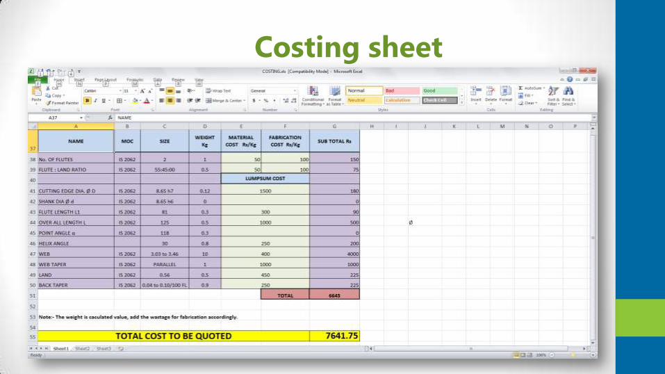
Costing sheet

Salient Features
• Generation of Process and Fabrication drawing automatically with a click of button.
• Managing of Data for Individual Process along with Machine setting for each type of activity and necessary drawing for the purpose.
• Bird’s Eye View & Real time tracking of Work-Order Progress
• Automatic design / selection of requisite tools necessary for the work order specific.
• Generates the raw material requirements
1/2
2/2
014

Process module• Assists you in generation of proses flow diagram.
• Each process can be defined and the inspection
parameters can be defined for each process.
• An approval process can be assigned to any process.
• Automatic generation of inspection reports.
• Rejection mapping and rejection analysis.
• Machine operator performance tracking.

Login
Login Screen
• Machine Operators - views only process related data & quantity
• Manager – views all the
Process data relevant to
the product.
• Top – Management –
Bird’s eye Views complete
Process layout
1/2
2/2
014

Dashboard
• Application Dashboard
1/2
2/2
014
Process Monitoring Dashboard,
that would be accessed by
Department Heads having a Bird’s
eye view and Real-Time Updates
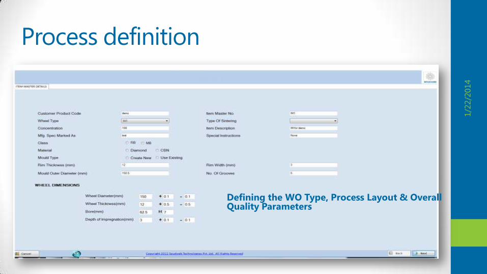
Process definition
1. Enquiry or Order Definition (Final Drawing / Product Requirement)
1/2
2/2
014
Defining the WO Type, Process Layout & Overall Quality Parameters
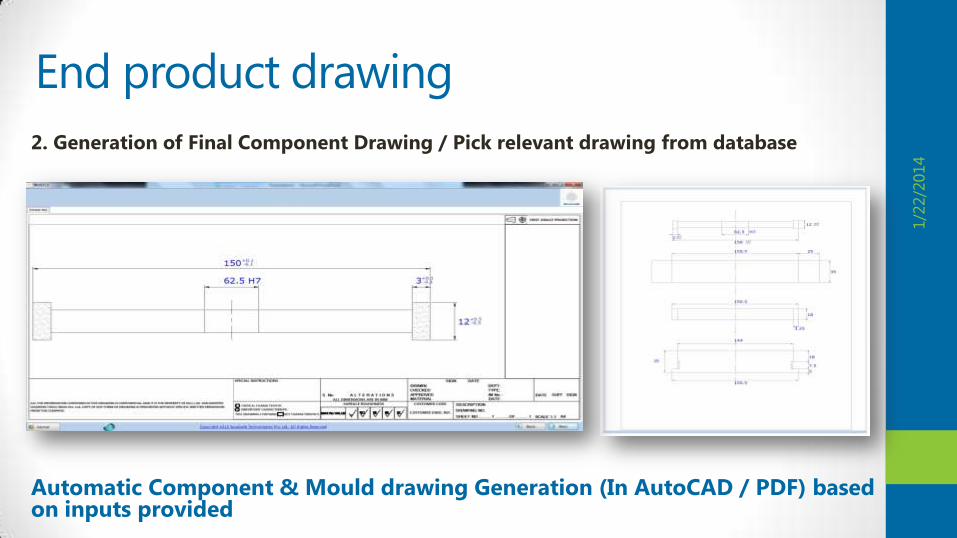
End product drawing
2. Generation of Final Component Drawing / Pick relevant drawing from database
1/2
2/2
014
Automatic Component & Mould drawing Generation (In AutoCAD / PDF) based on inputs provided

Process monitoring
3. Breakdown of Requirements to Individual Components like Type of Machine, Parameters, Process / Inspection etc.
1/2
2/2
014
* Note – The Users can create as many possible Process and modify the sequence in every new work order generated.

Process split up
4. Process Split up
• Pre- Requirement – Define if there is any prerequisite conditions prior to the process
• Process Requirement – Defining the complete process which includes drawings, Machine Set Parameters etc.
• Post Requirement – Defining the inspection and subject to approval shall follow the material handling instructions.
1/2
2/2
014

Process Definition
1/2
2/2
0145. Process Requirement – Defining the complete process which includes
process drawings, Machine Set Parameters etc.

Process rejection mapping
Defining Sub Process to handle specific operations and approvals for user accounts based on privileges
1/2
2/2
014

Approvals
Approvals for intermediary
Process like mandatory QC or
inspections could be
customized
1/2
2/2
014
Proceeding to the next
stage of the process tree
is prevented with the
pending processes.

Reports generation
1/2
2/2
014
Monitoring the Rejects Final Inspection Report

Contact Us
24
P R Venkatesh - +18324263640
|
+91 98409 07717
Bhaskar– +91 95434 06438
SPUDWEB Technologies
Private Limited# 43/18, Ground Floor, Gandhi
Nagar
3rd Main Road, Adyar, Chennai
- 600 020 TN, INDIA
Tel: +91 44 4266-6364 Email: