suzuki modular instrument system (smis) 4” display · thank you for buying the suzuki modular...
TRANSCRIPT

Suzuki Modular Instrument System
(SMIS) 4” Display Multi-function Gauge
Installation and Operation Instructions
988-0151-38B

Copyright © 2009 American Suzuki Motor Corp.
All rights reserved. No part of this manual may be copied, reproduced, republished, transmitted or distributed for any purpose, without prior written consent of American Suzuki Motor Corp. Any unauthorized commercial distribution of this manual is strictly prohibited.
Suzuki may find it necessary to change or end our policies, regulations and special offers at any time. We reserve the right to do so without notice. All features and specifications subject to change without notice. On the cover: SMIS 4” display shown.
For free owner's manuals and other information, visit our web site:
www.suzukimarine.com
American Suzuki Motor Corporation 3251 E. Imperial Hwy.
Brea, CA USA 92821-2486 Printed in USA.
4/6/09
1
Table of Contents Section 1: Introduction.................................................................. 3 Section 2: Installation ................................................................... 5 Preparation.................................................................................... 5
Recommended Tools and supplies............................................ 5 Installation Sequence................................................................ 5
Mounting the Unit ........................................................................ 5 Connecting to a NMEA 2000 Network .................................... 7
Understanding this manual………………………………………...10 Menu Commands..................................................................... 10
Section 3: Operation.................................................................... 11 Boat Setup ................................................................................... 11 Suzuki Engine Interface Configuration & Calibration…………12 Basic Menu .................................................................................. 15 Pages ............................................................................................ 15 Viewing Pages (Page Screen Rotation) ...................................... 15 Page Options................................................................................ 15
Engine Trim, Diagnostics, Fuel Manager & GPS Position .. 16 Clock & Single Analog ............................................................ 16 Dual Analog, Quad Analog, Single Digital & Dual Digital .. 17 Quad Digital, Synchronizer & Trim Tabs.............................. 17
Pages Menu .................................................................................. 18 Adding Pages ........................................................................... 18 Removing Pages .................................................................... 18d Page Scrolling .......................................................................... 19
Pop-Ups Setup .......................................................................... 19 Reset Values (Gauge)....…………………… ……...…............... 20 Lock Pages……………………………………………………..……21 Sleep Mode…………………………………………………………..21
Screen........................................................................................... 21 Backlight.................................................................................. 21 BLight Sync ............................................................................. 22 Contrast ................................................................................... 22 Reverse Video .......................................................................... 23
Audio Setup ................................................................................. 23 System Setup Menu .................................................................... 24
Engine Data ......................................................................... 24 Engine Warnings................................................................. 25 Bus Devices.......................................................................... 26
Sonar Alarms....................................................................... 26 Engine/Tank Configuration ................................................ 27 Reset Values: ....................................................................... 28
2
NMEA Info............................................................................... 28 System Information................................................................. 28
Speed Range ........................................................................ 28 Pressure Ranges .................................................................. 29
Change Units........................................................................... 29 Fuel Setup.................................................................................... 31
Refill Tank ............................................................................... 31 Partial Fill................................................................................ 32 Economy Speed Source ........................................................... 33 Fuel Remaining Source........................................................... 33 Reset Trip Fuel ........................................................................ 34 Reset Seasonal......................................................................... 34
Customizing Pages ...................................................................... 34 Single Analog........................................................................... 35 Dual Analog ............................................................................. 36 Quad Analog ............................................................................ 36 Single Digital ........................................................................... 36 Dual Digital ............................................................................. 37 Quad Digital ............................................................................ 38 Trim Tabs................................................................................. 39 Customize Trim Tabs: ............................................................. 39 Fuel Manager .......................................................................... 40
Section 4: Sensor Configuration & Calibration......................... 41 Temperature Configuration........................................................ 42 Fuel Flow Configuration w/ engine interface............................ 44 Calibrating Engine trim………… …………………………………46 Fluid Level Configuration .......................................................... 44
Fluid Level menu .................................................................... 47 Reset Values ............................................................................ 51
Calibrating Electronic Sensors................................................... 52 Calibrating Fluid Level............................................................... 52
2-Point Calibration.................................................................. 52 3-Point Calibration.................................................................. 53 5-Point Calibration.................................................................. 53
Pressure Sensor…………….…… ………………………………….55 Calibrating Pressure Sensor…………………………………...55
Calibrating Trim Tabs……………. ……………………………….. 55
3
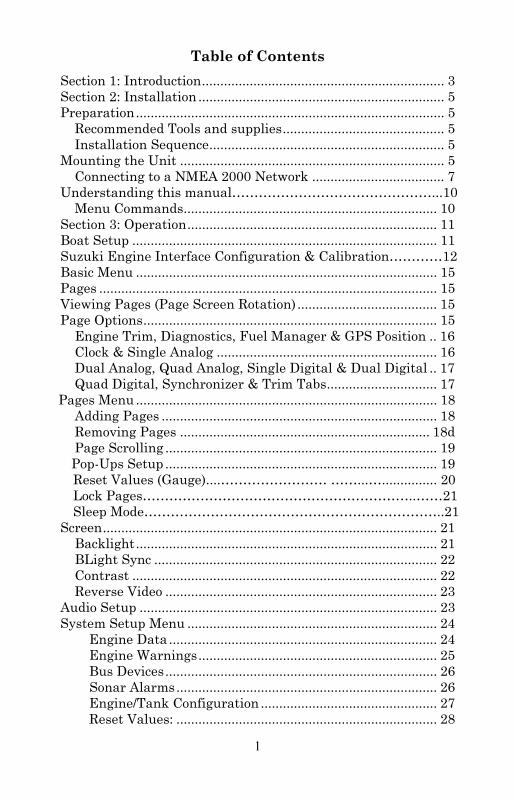
Section 1: Introduction Thank you for buying the Suzuki Modular Instrument System (SMIS) 4” display. Your unit is a high-quality, multi-function, digital gauge designed to work with NMEA 2000® network system devices.
This gauge will only work with a NMEA 2000 network. It MUST be connected to a NMEA 2000 network or it WILL NOT function. When properly installed, the SMIS 4” instrument will display information from a variety of Electronic sensors and other NMEA 2000 devices connected to the network.
A NMEA 2000 network using SMIS components.
All Suzuki NMEA 2000-capable devices are either NMEA 2000-certified or certification is pending. To get started with your new Suzuki gauge, first read the installation section. It contains instructions for installing the SMIS 4” display.
CAUTION
Installing NMEA 2000 devices is significantly different from installing Non NMEA components/devices. You should read all
of the installation instructions before proceeding.
4
After you've read those instructions, install the gauge and any sensors you may have purchased, then read the rest of this manual. Each sensor comes with its own installation instruction sheet, but this manual describes how the gauge operates with each sensor, and how to configure and calibrate the sensors. Your gauge packaging also includes another manual which contains complete instructions for creating or expanding a NMEA 2000 network. Suzuki teams up the powerful NMEA 2000 network standard with a fast-growing, cutting-edge family of Electronic Sensors. At press time, the product line includes the Fluid Level, Engine interface, Speed, Temp and Pressure sensors. And what's more exciting, there are others on the way! When you're ready to expand your network, see the Suzuki Genuine Accessory Catalog for ordering information.
CAUTION The storage and operation temperature range for your unit is from -4 degrees to +167 degrees Fahrenheit (-20 degrees to +75 degrees Celsius). Extended storage or operation in temperatures higher or lower than specified will damage the liquid crystal display in your unit. This type of damage is not covered by the warranty. For more information, contact the factory's Customer Service Department; phone numbers are inside the manual's back cover. When used in temperatures below 32 degrees Fahrenheit, the screen may require additional “warm up” time for all features to be visible.
• 15°F = 3 seconds to become visible • 10°F = 6 seconds to become visible • 5°F = 12 seconds to become visible • 0°F = 45 seconds to become visible • -5°F = 2 minutes to become visible • -10°F = 7 minutes to become visible • -15°F = 12 minutes to become visible
5
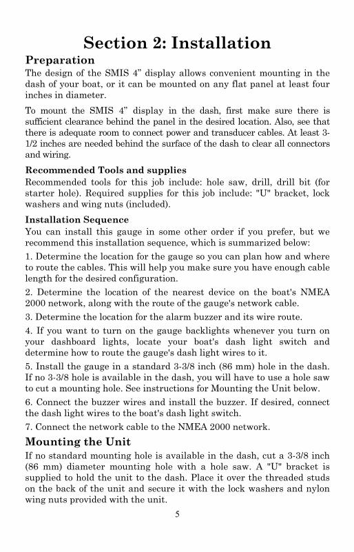
Section 2: Installation Preparation The design of the SMIS 4” display allows convenient mounting in the dash of your boat, or it can be mounted on any flat panel at least four inches in diameter. To mount the SMIS 4” display in the dash, first make sure there is sufficient clearance behind the panel in the desired location. Also, see that there is adequate room to connect power and transducer cables. At least 3-1/2 inches are needed behind the surface of the dash to clear all connectors and wiring. Recommended Tools and supplies Recommended tools for this job include: hole saw, drill, drill bit (for starter hole). Required supplies for this job include: "U" bracket, lock washers and wing nuts (included). Installation Sequence You can install this gauge in some other order if you prefer, but we recommend this installation sequence, which is summarized below: 1. Determine the location for the gauge so you can plan how and where to route the cables. This will help you make sure you have enough cable length for the desired configuration. 2. Determine the location of the nearest device on the boat's NMEA 2000 network, along with the route of the gauge's network cable. 3. Determine the location for the alarm buzzer and its wire route. 4. If you want to turn on the gauge backlights whenever you turn on your dashboard lights, locate your boat's dash light switch and determine how to route the gauge's dash light wires to it. 5. Install the gauge in a standard 3-3/8 inch (86 mm) hole in the dash. If no 3-3/8 hole is available in the dash, you will have to use a hole saw to cut a mounting hole. See instructions for Mounting the Unit below. 6. Connect the buzzer wires and install the buzzer. If desired, connect the dash light wires to the boat's dash light switch. 7. Connect the network cable to the NMEA 2000 network. Mounting the Unit If no standard mounting hole is available in the dash, cut a 3-3/8 inch (86 mm) diameter mounting hole with a hole saw. A "U" bracket is supplied to hold the unit to the dash. Place it over the threaded studs on the back of the unit and secure it with the lock washers and nylon wing nuts provided with the unit.
6
Secure unit to the dash using "U" bracket as shown.
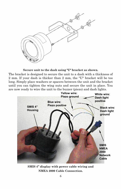
The bracket is designed to secure the unit to a dash with a thickness of 2 mm. If your dash is thicker than 2 mm, the "U" bracket will be too long. Simply place washers or spacers between the unit and the bracket until you can tighten the wing nuts and secure the unit in place. You are now ready to wire the unit to the buzzer (piezo) and dash lights.
SMIS 4” display with power cable wiring and
NMEA 2000 Cable Connection.
SMIS NMEA 2000 Network Cable
SMIS 4” Housing
Blue wire: Piezo positive
Yellow wire: Piezo ground
White wire: Dash light positive
Black wire: Dash light ground
7
Connecting the SMIS 4” display to the buzzer (piezo), the buzzer sounds when alarm and level warning are triggered. Wiring the unit to the dash lights, will turn on the SMIS 4” display backlight when the dash lights are turned on. If you do not want to use the buzzer or dash light wires, clip the bare ends off the wires, then cap them with wire nuts or electrical tape. To wire unit to the buzzer (piezo): 1. Connect the SMIS 4” display yellow buzzer ground wire to the buzzer (piezo) ground wire. 2. Now attach the SMIS 4” display white buzzer positive wire to the buzzer (piezo) positive wire. 3. Select a buzzer location that is protected from the elements, but will still allow you to hear it. Use the adhesive back on the buzzer to mount the buzzer to a flat, clean surface. To wire unit to dash lights: 1. Connect the SMIS 4” display black dash light ground wire to the dash light ground wire. 2. Now attach the SMIS 4” display white dash light positive wire to the dash light positive wire. NOTE: The Dash Light Wires of only one gauge need to be connected to enable the dash light features on all gauges on the network Connecting to a NMEA 2000 Network A network bus is an installed and operational network cable (backbone) running the length of your boat, already connected to a power supply and properly terminated. Such a bus provides network connection nodes at various locations around your boat. For more detailed information about setting up a NMEA 2000 network, refer to the NMEA 2000 Networks General Information document included with your gauge. This is similar to the telephone wiring in a house. If you pick up a phone in your living room, you can hear someone talking into the phone in the bedroom.

8
Pictured above is a 2 foot extension cable, T connector, 120-ohm male terminator and 120-ohm female terminator. NOTE: All connectors used to add your gauge to a NMEA 2000 network will be black Devicenet connectors as shown above.
For complete instructions on setting up a new NMEA 2000 network or expanding an existing one, refer to the NMEA 2000 Installation Instructions packed with your operation manual. Network Nodes A network bus is built of network nodes spread along a backbone. Network nodes are made by fitting T-shaped connectors into the backbone (using the sockets on the sides), and attaching any NMEA 2000 device at the bottom of the "T." Using our telephone example, the T connectors are similar to telephone jacks. The backbone is like the phone wiring running through a house. Phones in a house must be connected to each other to communicate, and in the same way only sensors and display units plugged into the NMEA 2000 network can share information. Connections found in the middle of the bus will have one or more of these T-shaped connectors with the backbone cables plugged into both sides. Connections at the end of a network will have the backbone plugged into one side, and a terminator plugged into the other, as shown in the following figure.

9
NMEA 2000 network node located at the end of a NMEA 2000 bus.
Adding a Network Node You can add a node anywhere along the network backbone where a connection already exists. This connection could be at the end of the network (between a T connector and a terminator), between two T connectors, between a T connector and a backbone extension cable, or between two extension cables. Wherever you want to add the new node, simply separate the sockets of the old connection and attach your new T connector between them.
Add a new device to a NMEA 2000 bus by attaching a T connector
between two T connectors, between a T connector and the end terminator, or between two backbone extension cables.
If you want to add a node at the end of the line (as shown in the previous figure), remove the terminator from the very last connector, securely attach the new T connector, and then attach the terminator on the new connector. Either method will allow you to add a device.
NOTE: If you add a Fluid Level or Water Pressure Sensor to the network, you must go through Boat Setup so the engine-tank configuration will be consistent among the sensors in the network. Follow the Boat Setup procedure included in Section 3: Operations.
Backbone cable (to rest of bus)
SMIS device needs an open T.
Terminator at the very end of the bus
Cable from sensor or display unit
Existing network node
Attach terminator at end of bus.
SMIS device connects to new T connector. Add T-shaped con-
nector to add device to bus.
T connector
10
Additional Network Information Further instructions on creating or expanding a SMIS network are illustrated in the NMEA 2000 network setup booklet. Understanding this manual Most instructions in the manual are listed as numbered steps. Keypad commands appear as boldface type, making it easy to skim through instructions and pick out what command to use. Up and Down The Up and Down keys help you navigate through menus, select (highlight) menu items, and are used to make adjustments to input numbers in dialog boxes. They are shown as UP and DOWN in this manual. Menu When instructed to press the menu key, menu will be shown as MENU. The menu key is used to access the main menu. Pages/Enter The Pages/Enter key is used to execute commands and to scroll forward through pages set for display on the main screen. The Pages/Enter key will be shown as ENTER in this manual. Exit The Exit key is used to close menus and remove dialogs, windows and messages from the screen. Shown as EXIT in this manual, it is also used to scroll backward through pages set for display on the main screen. Menu Commands A menu command or a menu option will appear in small capital letters, like — ROUTE PLANNING. When you see a word in command text, you are supposed to take action, by selecting (highlighting) this command or option from a menu. Instructions = Menu Sequences Most functions performed with this unit are described as a sequence of keystrokes. Instructions for accessing a menu will look like this:
1. To access the Bus Devices list, press MENU, use the UP and DOWN keys to select SYSTEM SETUP and press ENTER. 2. Highlight BUS DEVICES and press ENTER. The Bus Devices list will appear, showing all devices on your NMEA 2000 network. *NOTE: A new feature has been added to the gauge allowing you to go directly to system set up by pressing the MENU button twice. You can then scroll to your choice and make the selection you wish.

11
Section 3: Operation The displays and settings in this digital gauge are controlled by a five-button keypad. The buttons are UP, DOWN, MENU, ENTER and EXIT. The MENU key gives you access to the basic menu. The UP and DOWN keys are used to scroll through and highlight menu items. The PAGES/ENTER key (also referred to as the ENTER key) allows you to scroll forward through pages, execute commands and select items from menus. The EXIT key is used to close menus and scroll backward through pages.
SMIS 4” display keypad.
Boat Setup When the SMIS 4” display is turned on the first time, the Boat Setup menu will appear. You will not be able to proceed without completing Boat Setup. If, however, you have one or more of the following devices — engine interface, Fluid Level or Pressure Sensor — already configured in the network with the same engine-tank configuration, you WILL NOT have to go through boat setup when adding a new gauge to the network. After adding the gauge to the network, the Boat Setup menu will be cleared from the screen and the unit will begin normal operation in 1-2 seconds.
NOTE: If you add a Fluid Level, Pressure sensor, or Engine Interface to the network, you must go through Boat Setup so the engine-tank configuration will be consistent among sensors in the network.
To execute Boat Setup: 1. With Boat Setup highlighted on the screen, press ENTER. A menu will appear, allowing you to choose the number of engines and fuel tanks on your vessel. The Boat Setup menu options are: 1 Eng/1 Tank, 1 Eng/2 Tank, 2 Eng/1 Tank, 2 Eng/2 Tanks, 3 Eng/1 Tank or 3 Eng/3 Tanks. 2. Use the UP and DOWN keys to select the engine-tank configuration that applies to your vessel and press ENTER. After setting the engine/tank configuration, the Tank Size menu will appear with up to three options (Port Tank, Center Tank and Starboard Tank), depending

12
on the engine tank configuration you chose. (If you selected one tank during Boat Setup, you will be taken directly to the Setting Tank Size Window in Step 3.) 3. Select the desired tank and press ENTER, which will open the Setting Tank Size window. 4. Use the UP and DOWN keys to input the number of gallons the tank will hold and press ENTER. Press EXIT and repeat steps 3 and 4 for each of the remaining tanks. 5. After all tanks on your vessel have been set up, press EXIT repeatedly to get back to the main display.
NOTE: If you chose the wrong engine-tank configuration during Boat Setup, you will have to reset your engine-tank configuration to get back to Boat Setup.
Configuration and Calibration The following instructions show how to use the SMIS 4" multi-function gauge to configure and calibrate (fuel and engine trim) a Suzuki Engine Interface. Other information in this segment covers how to set a Fuel Warning and how to perform a factory Reset. To configure a Suzuki Engine Interface: 1. Press MENU MENU, use the UP and DOWN keys to scroll to Bus Devices. 2. Highlight BUS DEVICES and press ENTER. The Bus Devices list will appear. 3. Select UNCFG ENG INT and press ENTER. The following message will appear: Press Enter to Configure Eng Intrfc. 4. Press ENTER. You will be asked to select the engine year model. Highlight the year model and press ENTER. The following list of Suzuki engine models will appear: DF40, DF50, DF60, DF70, DF80, DF90, DF100, DF115, DF140, DF150, DF175, DF200, DF225, DF250 and DF300. NOTE: John, you might want to leave out the specific engine models to keep this manual more future compabitle. 5. Select your engine model from the list and press ENTER. The Select Engine menu will appear with up to three options (Port, Center and Starboard), depending on your engine-tank configuration. (If you chose a single engine configuration during Boat Setup, you will be taken back to the main display.) 6. Highlight the engine (Port, Center or Starboard) connected to your engine interface and press ENTER. Press EXIT repeatedly to return to the main display.
13
To unconfigure an Suzuki Engine Interface (Unset Engine): 1. Press MENU MENU and use the UP and DOWN keys to scroll to BUS DEVICES. 2. Highlight BUS DEVICES and press ENTER to open the Bus Devices list. 3. Select the desired engine interface and press ENTER. The Engine Interface menu will appear. Select UNSET ENGINE and press ENTER. The following message will appear: Press ENTER to UnConfig Device Name. 4. Press ENTER and you will be directed back to the Bus Devices list., where the engine interface you unconfigured will be shown as UnCfg Eng Int. Reconfiguring Suzuki engine interface (multiple engines only): The Change Engine command is used to switch the current configuration of a Suzuki Engine Interface with the configuration from a different engine. Change Engine, however, will only appear on your gauge's menu if you are using an engine-tank configuration for two or more engines. If all engine interfaces on your vessel are configured, you will have to unconfigure an engine interface to free up its configuration name (Port, Center, Starboard). To reconfigure an engine interface (Change Engine): The steps below show how to switch the configuration name of an engine interface from the Port engine to the Starboard engine. If all three engine interfaces are configured, leaving no name configuration available, follow the first set of instructions below. If the desired configuration name is available, follow the second set of instructions below. All engine interfaces configured (Configuration name unavailable): 1. Press MENU MENU and use the UP and DOWN keys to scroll to BUS DEVICES. 2. Highlight BUS DEVICES and press ENTER. The Bus Devices list will appear. 3. Select PORT ENGINE and press ENTER. Highlight UNSET ENGINE and press ENTER. The following message will appear: Press Enter to UnConfig Device Name. 4. Press ENTER. You will be taken back to the Bus Devices list, where the engine adapter will now be displayed as UnCfg Eng Int. 5. Select Starboard Engine and press ENTER. 6. Highlight CHANGE ENGINE and press ENTER. The Select Engine menu will appear with up to three options (Port, Center and Starboard). 7. Select PORT and press ENTER. You will be taken back to the Bus Devices list.
14
8. Highlight UnCfg Eng Int and press ENTER. The following message will appear: Press Enter to Configure Eng Intrfc. 9. Press ENTER, which will open the Suzuki Engine Model menu. Select the model of Suzuki engine on your vessel and press ENTER. The Select Engine menu will appear with up to three options (Port Center and Starboard). 10. Choose Starboard and press ENTER. You will be taken back to the Bus Devices list where the engine interfaces will be shown with their new configuration names. If desired configuration name available: 1. Press MENU MENU and use the UP and DOWN keys to scroll to BUS DEVICES. 2. Highlight BUS DEVICES and press ENTER. The Bus Devices list will appear. 3. Select the engine interface you want to reconfigure and press ENTER. Highlight CHANGE ENGINE and press ENTER. The Select Engine menu will appear with up to three options (Port, Center or Starboard). 4. Choose the desired configuration name and press ENTER. You will be taken back to the Bus Devices list, where the engine adapter you reconfigured will be displayed with its new configuration name. Fuel Warning (Fuel Wrng) Fuel Warning allows you to set a Low level or High level alarm for each Suzuki Engine Interface on the network. A pop-up window will appear if the fuel rises above or falls below a threshold of your choosing. To set a fuel warning: 1. Press MENU MENU and use the UP and DOWN keys to scroll to BUS DEVICES. 2. Highlight BUS DEVICES and press ENTER to open the Bus Devices list. 3. Select the desired engine interface and press ENTER. That will open the engine interface menu. 4. Highlight FUEL WRNG and press ENTER. The Select Level menu will appear with two options: Low Level and High Level. Typically, a Fuel Level warning is used to alert you when your vessel is running low on fuel, so highlight LOW LEVEL and press ENTER. The Set Level Percentage window will appear, allowing you to set the level warning to the desired percentage of tank capacity (0-100%). It will be set to OFF by default. (To turn off a level warning select Off.) 5. Use the UP and DOWN keys to set the desired fuel warning percentage and press ENTER. You will be taken back to the Bus Devices list.
15
Reset Values Accessing the Reset Values command from the Engine Interface menu, allows you to reset configuration and calibration settings for a particular engine interface. To reset values: 1. Press MENU MENU and use the UP and DOWN keys to scroll to BUS DEVICES. 2. Highlight BUS DEVICES and press ENTER. Select the engine connected to the interface you want to reset and press ENTER. 3. Choose RESET VALUES from the Engine Interface menu and press ENTER. The following message will appear: Press Enter to Reset Device Values. 4. Press ENTER and you will be taken back to the Bus Devices list, where the engine adapter now will be displayed as UnCfg Eng Int. Selecting to Reset Values of an engine interface deletes the engine and tank configuration from that engine interface. You will have to reenter the engine and tank configuration .
4” SMIS Basic Menu The SMIS 4” display has 12 page screens that can be customized with the data of your choosing. Each page has its own basic menu. Basic menus vary from page to page, but all contain these standard menu options: Pages, Screen, Audio Setup and System Setup. Pages that can be customized also include Customize on the basic menu. Pages Your unit can display up to 16 page screens. You could, for example, add 12 different pages then add some pages more than once, customizing them differently each time. Viewing Pages (Page Screen Rotation) The Page Screen Rotation consists of multiple pages that have been set up for display. Once pages have been added to the page screen rotation, they can be set to scroll across the screen automatically or manually. Use the ENTER and EXIT keys to manually scroll pages across the screen. Pressing the ENTER key moves the scroll in one direction. Pushing the EXIT key moves the scroll in the other direction. You will use the Page Scrolling feature to set up pages for automatic scrolling. See page 19 for more detailed information about Page Scrolling. Page Options The SMIS 4” display has 14 different pages that may be added to the page screen rotation. They are: Engine Trim, Diagnostics, Fuel
16
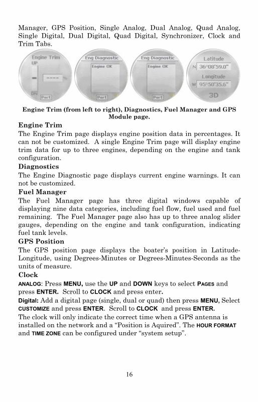
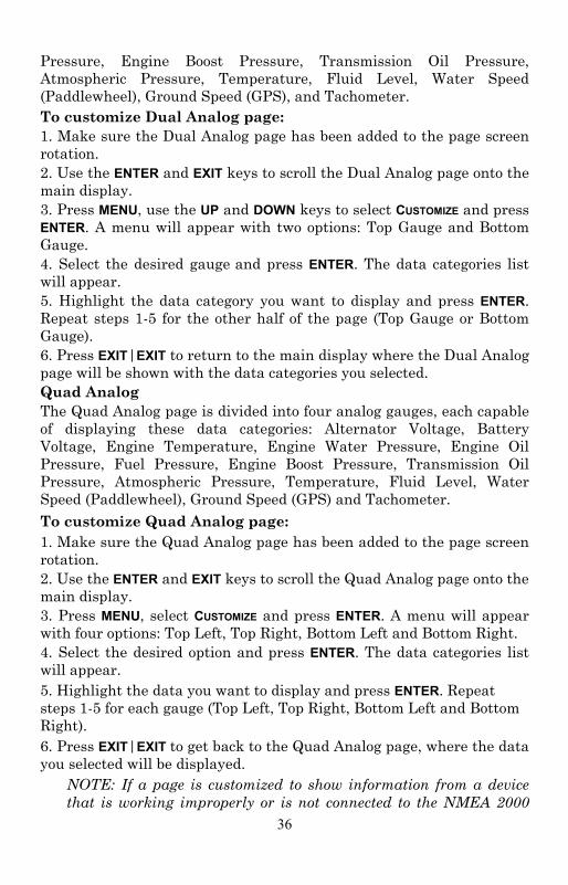
Manager, GPS Position, Single Analog, Dual Analog, Quad Analog, Single Digital, Dual Digital, Quad Digital, Synchronizer, Clock and Trim Tabs.
Engine Trim (from left to right), Diagnostics, Fuel Manager and GPS
Module page. Engine Trim The Engine Trim page displays engine position data in percentages. It can not be customized. A single Engine Trim page will display engine trim data for up to three engines, depending on the engine and tank configuration. Diagnostics The Engine Diagnostic page displays current engine warnings. It can not be customized. Fuel Manager The Fuel Manager page has three digital windows capable of displaying nine data categories, including fuel flow, fuel used and fuel remaining. The Fuel Manager page also has up to three analog slider gauges, depending on the engine and tank configuration, indicating fuel tank levels. GPS Position The GPS position page displays the boater’s position in Latitude-Longitude, using Degrees-Minutes or Degrees-Minutes-Seconds as the units of measure. Clock ANALOG: Press MENU, use the UP and DOWN keys to select PAGES and press ENTER. Scroll to CLOCK and press enter. Digital: Add a digital page (single, dual or quad) then press MENU, Select CUSTOMIZE and press ENTER. Scroll to CLOCK and press ENTER. The clock will only indicate the correct time when a GPS antenna is installed on the network and a “Position is Aquired”. The HOUR FORMAT and TIME ZONE can be configured under “system setup”.
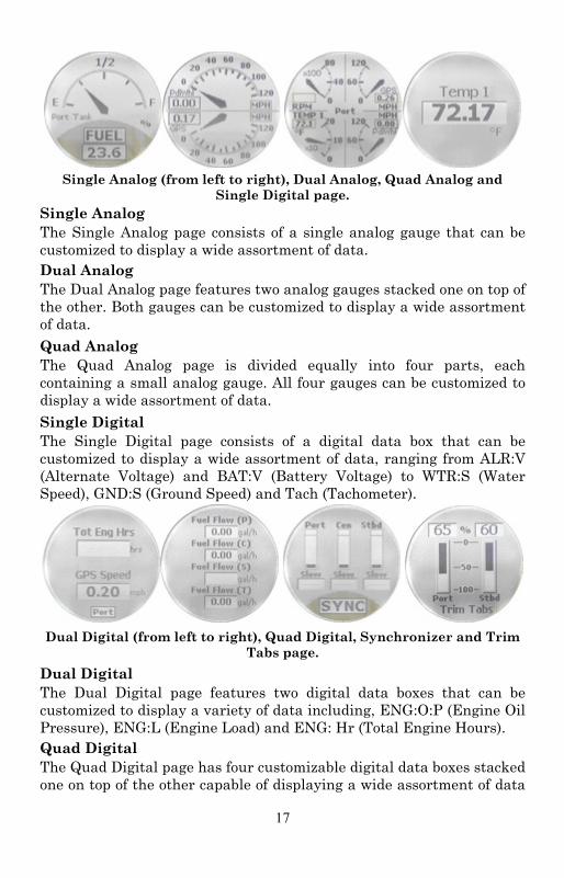
17
Single Analog (from left to right), Dual Analog, Quad Analog and
Single Digital page. Single Analog The Single Analog page consists of a single analog gauge that can be customized to display a wide assortment of data. Dual Analog The Dual Analog page features two analog gauges stacked one on top of the other. Both gauges can be customized to display a wide assortment of data. Quad Analog The Quad Analog page is divided equally into four parts, each containing a small analog gauge. All four gauges can be customized to display a wide assortment of data. Single Digital The Single Digital page consists of a digital data box that can be customized to display a wide assortment of data, ranging from ALR:V (Alternate Voltage) and BAT:V (Battery Voltage) to WTR:S (Water Speed), GND:S (Ground Speed) and Tach (Tachometer).
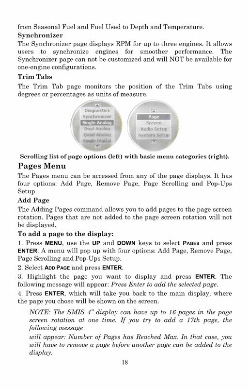
Dual Digital (from left to right), Quad Digital, Synchronizer and Trim
Tabs page. Dual Digital The Dual Digital page features two digital data boxes that can be customized to display a variety of data including, ENG:O:P (Engine Oil Pressure), ENG:L (Engine Load) and ENG: Hr (Total Engine Hours). Quad Digital The Quad Digital page has four customizable digital data boxes stacked one on top of the other capable of displaying a wide assortment of data
18
from Seasonal Fuel and Fuel Used to Depth and Temperature. Synchronizer The Synchronizer page displays RPM for up to three engines. It allows users to synchronize engines for smoother performance. The Synchronizer page can not be customized and will NOT be available for one-engine configurations. Trim Tabs The Trim Tab page monitors the position of the Trim Tabs using degrees or percentages as units of measure.
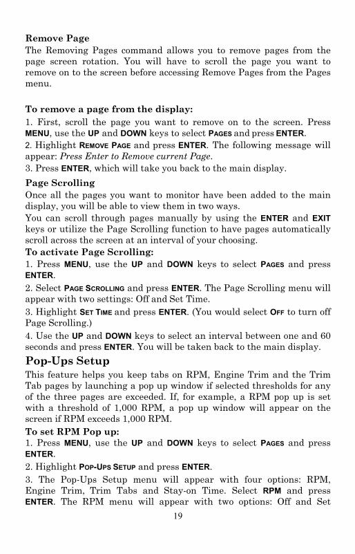
Scrolling list of page options (left) with basic menu categories (right).
Pages Menu The Pages menu can be accessed from any of the page displays. It has four options: Add Page, Remove Page, Page Scrolling and Pop-Ups Setup. Add Page The Adding Pages command allows you to add pages to the page screen rotation. Pages that are not added to the page screen rotation will not be displayed. To add a page to the display: 1. Press MENU, use the UP and DOWN keys to select PAGES and press ENTER. A menu will pop up with four options: Add Page, Remove Page, Page Scrolling and Pop-Ups Setup. 2. Select ADD PAGE and press ENTER. 3. Highlight the page you want to display and press ENTER. The following message will appear: Press Enter to add the selected page. 4. Press ENTER, which will take you back to the main display, where the page you chose will be shown on the screen.
NOTE: The SMIS 4” display can have up to 16 pages in the page screen rotation at one time. If you try to add a 17th page, the following message will appear: Number of Pages has Reached Max. In that case, you will have to remove a page before another page can be added to the display.
19
Remove Page The Removing Pages command allows you to remove pages from the page screen rotation. You will have to scroll the page you want to remove on to the screen before accessing Remove Pages from the Pages menu. To remove a page from the display: 1. First, scroll the page you want to remove on to the screen. Press MENU, use the UP and DOWN keys to select PAGES and press ENTER. 2. Highlight REMOVE PAGE and press ENTER. The following message will appear: Press Enter to Remove current Page. 3. Press ENTER, which will take you back to the main display. Page Scrolling Once all the pages you want to monitor have been added to the main display, you will be able to view them in two ways. You can scroll through pages manually by using the ENTER and EXIT keys or utilize the Page Scrolling function to have pages automatically scroll across the screen at an interval of your choosing. To activate Page Scrolling: 1. Press MENU, use the UP and DOWN keys to select PAGES and press ENTER. 2. Select PAGE SCROLLING and press ENTER. The Page Scrolling menu will appear with two settings: Off and Set Time. 3. Highlight SET TIME and press ENTER. (You would select OFF to turn off Page Scrolling.) 4. Use the UP and DOWN keys to select an interval between one and 60 seconds and press ENTER. You will be taken back to the main display. Pop-Ups Setup This feature helps you keep tabs on RPM, Engine Trim and the Trim Tab pages by launching a pop up window if selected thresholds for any of the three pages are exceeded. If, for example, a RPM pop up is set with a threshold of 1,000 RPM, a pop up window will appear on the screen if RPM exceeds 1,000 RPM. To set RPM Pop up: 1. Press MENU, use the UP and DOWN keys to select PAGES and press ENTER. 2. Highlight POP-UPS SETUP and press ENTER. 3. The Pop-Ups Setup menu will appear with four options: RPM, Engine Trim, Trim Tabs and Stay-on Time. Select RPM and press ENTER. The RPM menu will appear with two options: Off and Set
20
Threshold. 4. Highlight SET THRESHOLD and press ENTER. (You would select OFF to turn off a threshold.) 5. Use the UP and DOWN keys to select a threshold between 50 and 3,000 RPM and press ENTER. You will be taken back to the main display. To set Engine Trim Pop-up: 1. Press MENU, use the UP and DOWN keys to select PAGES and press ENTER. 2. Highlight POP-UPS SETUP and press ENTER. 3. Select ENGINE TRIM and press ENTER. The Engine Trim menu will appear with two options: Off and Set Threshold. 4. Highlight SET THRESHOLD and press ENTER. (You would select OFF to turn off a threshold.) 5. Use the UP and DOWN keys to select a threshold between 3% and 50% and press ENTER. You will be taken back to the main display. To set Trim Tabs Pop up: 1. Press MENU, use the UP and DOWN keys to select PAGES and press ENTER. 2. Highlight POP-UPS SETUP and press ENTER. 3. Select TRIM TABS and press ENTER. The Trim Tabs menu will appear with two options: Off and Set Threshold. (You would select OFF to turn off a threshold.) 4. Highlight SET THRESHOLD and press ENTER. 5. Use the UP and DOWN keys to select a threshold between 3% and 50% and press ENTER. You will be taken back to the main display. Stay-On Time: The Stay-On Time command allows you to choose how long a pop up will remain on the screen once it is triggered. The Stay-On Time setting will affect all three Pop-up Pages. 1. Press MENU, use the UP and DOWN keys to select PAGES and press ENTER. Highlight POP-UPS SETUP and press ENTER 2. Select STAY-ON TIME and press ENTER. 3. Use the UP and DOWN keys to input the amount of time a pop up will remain on the screen. The stay-on time for a pop up may be set between 2 and 15. Press ENTER. You will be taken to the main display. Reset Values (Gauge)
21
If you have added, removed or changed pages that are not what you wanted to do, you can reset the gauges back to their factory default by: Press MENU MENU, scroll to RESET VALUES and press ENTER. If you choose PAGES you will go back to the 3 factory default pages. If you choose SETTINGS, it leaves the existing pages but puts all gauge settings back to factory defaults. If you choose ALL, it takes all pages and settings back to original factory default. Lock Pages Allows you to password protect the following pages to prevent tampering with your gauge configuration: CUSTOMIZE, PAGES, FUEL SETUP, ENG/TANK SETUP & BUS DEVICES. The 4 digit password is the last 4 digits of the NMEA serial number listed under SYSTEM SETUP – NMEA INFO. This page can always be accessed and cannot be locked out. To lock any of the listed pages you will press MENU MENU, scroll to LOCK PAGES press ENTER. You will be asked to enter your 4 digit password. The up and down buttons will scroll through numbers 0 ~ 9 and the MENU button will move to the next digit. Once you have the password displayed press ENTER. Select the pages you wish to protect by highlighting the check boxes. You can use the exit key to go back to an existing page when all your selections have been made. Any attempt to access a locked page will require password entry. Sleep Mode When using a quad power node on an SMIS network with multiple devices (GPS / Chartplotters, etc) we have incorporated the ability to put the gauges in sleep mode. When other devices on the active network are being used and the engine ignition key is shut off, the gauges will go into sleep mode after 15 seconds when the feature is activated. Touching any of the buttons on a gauge will turn the gauge back on for 15 seconds or turning the engine ignition key back to the on position will turn the gauge back on until the key is turned back off and then after 10 seconds it will go back into sleep mode. Press MENU MENU and use the UP and DOWN keys to scroll to SLEEP MODE. Press ENTER and you will be able to turn the SLEEP MODE on or off here. Screen Accessing the Screen menu allows you to make adjustments to the appearance of the screen. There are three options: Backlight, Contrast and Reverse Video.

22
Backlight The Backlight feature allows you to brighten or dim the light in the SMIS 4” display.
Basic menu with Screen highlighted (left). Screen option menu
(center) with Set Backlight window (right). To adjust Backlight: 1. Press MENU, use the UP and DOWN keys to select SCREEN and press ENTER. 2. Highlight BACKLIGHT and press ENTER. The Backlight menu will appear with two options: BLight Sync (Backlight Sync) and Adjust. 3. Select ADJUST and press ENTER. 4. A vertical scrollbar will appear. Use the UP and DOWN keys to set the backlight to a desired level. Press EXIT to return to the Backlight menu. Backlight Sync (BLight Sync) (Defaulted ON) By turning on the Backlight Sync function, all the backlight levels for components on the network may be controlled by any of the gauges or head units in the network. If you adjust the backlight on one of the gauges or display units, the backlight levels from the other gauges and display units will be changed, too. To set Backlight Sync 1. Press MENU, use the UP and DOWN keys to select SCREEN and press ENTER. 2. Highlight BACKLIGHT and press ENTER. The Backlight menu will appear with two options: BLight Sync (Backlight Sync) and Adjust. 3. Highlight BLIGHT SYNC and press ENTER, which will open the BLight Sync menu with two options: On and Off. Turning on Backlight Sync will cause the backlight level for all gauges on the network to be synchronized with the backlight level on your SMIS 4” display. 4. Select the desired option (ON or OFF) and press ENTER to be directed to the main display.
23
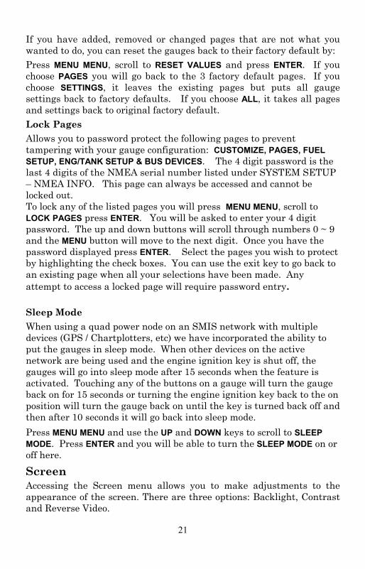
Contrast The Contrast feature allows you to darken or lighten the display screen. To adjust Contrast: 1. Press MENU, use the UP and DOWN keys to select SCREEN and press ENTER. Select CONTRAST from the Screen menu and press ENTER, which will launch the Contrast Adjustment vertical scrollbar. 2. Use the UP and DOWN keys to move the bar to a desired level. 3. Press EXIT to return to the Screen menu or press ENTER to return to the main display.
Contrast is highlighted on the Screen menu (left). The Contrast Adjust window (center). Reverse Video highlighted on Screen menu (right).
Reverse Video (Defaulted OFF) The Reverse Video function swaps the position of dark and light colors. The dark text, which is on top of a light background, will be switched to light text on top of a dark background. This feature, typically, is used to darken the display for nighttime use. Changing the status of Reverse Video on one gauge will change it on all gauges on the network. To turn on Reverse Video: 1. Press MENU, use the UP and DOWN keys to select SCREEN, and press ENTER. 2. Highlight REVERSE VIDEO and press ENTER. You will notice the dark and light colors have been swapped for one another. 3. To switch Reverse Video to its previous setting, return to the Screen menu, select REVERSE VIDEO and press ENTER. 4. Press EXIT|EXIT to return to the main display.
Audio Setup Audio Setup gives you access to the unit's audio functions. There are two options on the Audio Setup menu: Key Sounds and Alarm Sounds. Key Sounds When Key Sounds are turned on, a tone will sound every time you push the UP, DOWN, MENU, ENTER and EXIT keys. When you turn off Key Sounds, no tone will sound when you depress the keys.
24
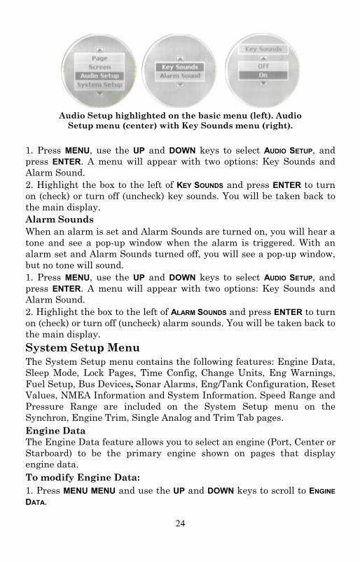
Audio Setup highlighted on the basic menu (left). Audio
Setup menu (center) with Key Sounds menu (right). 1. Press MENU, use the UP and DOWN keys to select AUDIO SETUP, and press ENTER. A menu will appear with two options: Key Sounds and Alarm Sound. 2. Highlight the box to the left of KEY SOUNDS and press ENTER to turn on (check) or turn off (uncheck) key sounds. You will be taken back to the main display. Alarm Sounds When an alarm is set and Alarm Sounds are turned on, you will hear a tone and see a pop-up window when the alarm is triggered. With an alarm set and Alarm Sounds turned off, you will see a pop-up window, but no tone will sound. 1. Press MENU, use the UP and DOWN keys to select AUDIO SETUP, and press ENTER. A menu will appear with two options: Key Sounds and Alarm Sound. 2. Highlight the box to the left of ALARM SOUNDS and press ENTER to turn on (check) or turn off (uncheck) alarm sounds. You will be taken back to the main display. System Setup Menu The System Setup menu contains the following features: Engine Data, Sleep Mode, Lock Pages, Time Config, Change Units, Eng Warnings, Fuel Setup, Bus Devices, Sonar Alarms, Eng/Tank Configuration, Reset Values, NMEA Information and System Information. Speed Range and Pressure Range are included on the System Setup menu on the Synchron, Engine Trim, Single Analog and Trim Tab pages. Engine Data The Engine Data feature allows you to select an engine (Port, Center or Starboard) to be the primary engine shown on pages that display engine data. To modify Engine Data: 1. Press MENU MENU and use the UP and DOWN keys to scroll to ENGINE DATA.
25
2. Highlight ENGINE DATA and press ENTER to open the Select Engine menu with up to three options: Port, Center and Starboard. 3. Select the primary engine (Port, Center or Starboard) to be displayed and press ENTER. A confirmation message will appear. If, for example, you selected the Port engine the following message will appear: Press Enter to change to Port Engine. 4. Press ENTER. Pages that display engine data will now pull the data from the Port engine. Engine Warnings The Engine Warnings feature allows you to set an alarm for one or more engines. There are up to five options in the Engine Alarms menu, depending on the number of engines chose during Boat Setup. The options are All Engines, Port, Center, Starboard and Off. The default setting is All Engines. (If you have a single-engine configuration, the only options on the Engine Warning menu will be on and off.) 1. Press MENU MENU and use the UP and DOWN keys to scroll to ENGINE WARNINGS. 2. Highlight ENGINE WARNINGS and press ENTER to access the Engine Warnings menu.
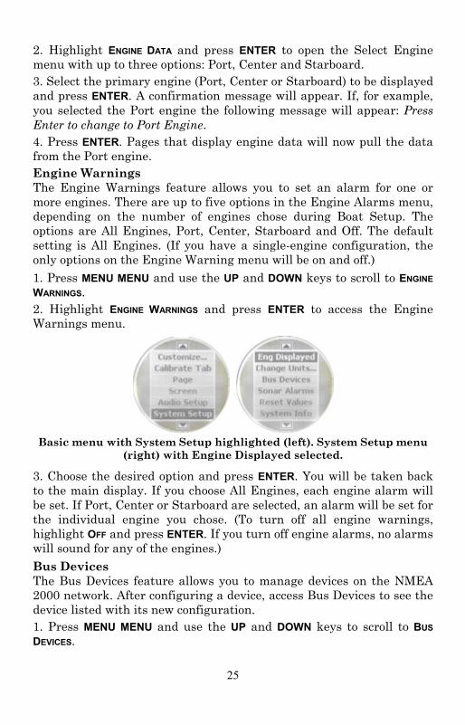
Basic menu with System Setup highlighted (left). System Setup menu
(right) with Engine Displayed selected.
3. Choose the desired option and press ENTER. You will be taken back to the main display. If you choose All Engines, each engine alarm will be set. If Port, Center or Starboard are selected, an alarm will be set for the individual engine you chose. (To turn off all engine warnings, highlight OFF and press ENTER. If you turn off engine alarms, no alarms will sound for any of the engines.) Bus Devices The Bus Devices feature allows you to manage devices on the NMEA 2000 network. After configuring a device, access Bus Devices to see the device listed with its new configuration. 1. Press MENU MENU and use the UP and DOWN keys to scroll to BUS DEVICES.
26
2. Highlight BUS DEVICES and press ENTER. The Bus Devices list will appear, showing all devices detected on the network. 3. Press EXIT repeatedly to get back to the main display. Sonar Alarms Sonar alarms allow you to set alarms that will alert you as water depth changes around your vessel. If the depth rises above (Deep Alarm) or falls below (Shallow Alarm) a depth threshold of your choosing, an alarm will sound. To set the Shallow Alarm: The shallow alarm will sound when your vessel enters water more shallow than the selected shallow alarm threshold. 1. Press MENU MENU and use the UP and DOWN keys to scroll to SONAR ALARMS. 2. Highlight Sonar Alarms and press ENTER to open the Sonar Alarms menu with two options: Shallow and Deep. 3. Select SHALLOW and press ENTER. The Shallow menu will appear with two options: Off and Set Depth. 4. Select SET DEPTH and press ENTER to open the Set Depth menu. (Choose OFF to turn off the Shallow Alarm). 5. Use the UP and DOWN keys to set the alarm to the desired depth and press ENTER. Press EXIT to return to the Sonar Alarms menu. To set the Deep Alarm: The deep alarm will sound when your vessel enters water deeper than the selected deep alarm threshold. 1. Press MENU MENU and use the UP and DOWN keys to scroll to SONAR ALARMS. 2. Highlight Sonar Alarms and press ENTER to open the Sonar Alarms menu with two options: Shallow and Deep. 3. Select DEEP and press ENTER. The Shallow menu will appear with two options: Off and Set Depth. 4. Select SET DEPTH and press ENTER. (Choose OFF to turn off the Deep Alarm). 5. Use the UP and DOWN keys to set the alarm to the desired depth, then press EXIT repeatedly to get back to the main display.
27
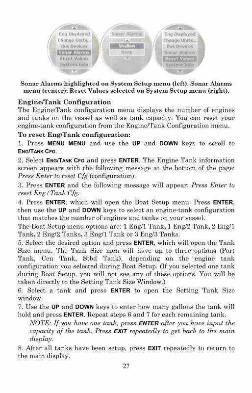
Sonar Alarms highlighted on System Setup menu (left). Sonar Alarms menu (center); Reset Values selected on System Setup menu (right).
Engine/Tank Configuration The Engine/Tank configuration menu displays the number of engines and tanks on the vessel as well as tank capacity. You can reset your engine-tank configuration from the Engine/Tank Configuration menu. To reset Eng/Tank configuration: 1. Press MENU MENU and use the UP and DOWN keys to scroll to ENG/TANK CFG. 2. Select ENG/TANK CFG and press ENTER. The Engine Tank information screen appears with the following message at the bottom of the page: Press Enter to reset Cfg (configuration). 3. Press ENTER and the following message will appear: Press Enter to reset Eng/Tank Cfg. 4. Press ENTER, which will open the Boat Setup menu. Press ENTER, then use the UP and DOWN keys to select an engine-tank configuration that matches the number of engines and tanks on your vessel. The Boat Setup menu options are: 1 Eng/1 Tank, 1 Eng/2 Tank, 2 Eng/1 Tank, 2 Eng/2 Tanks, 3 Eng/1 Tank or 3 Eng/3 Tanks. 5. Select the desired option and press ENTER, which will open the Tank Size menu. The Tank Size men will have up to three options (Port Tank, Cen Tank, Stbd Tank), depending on the engine tank configuration you selected during Boat Setup. (If you selected one tank during Boat Setup, you will not see any of these options. You will be taken directly to the Setting Tank Size Window.) 6. Select a tank and press ENTER to open the Setting Tank Size window. 7. Use the UP and DOWN keys to enter how many gallons the tank will hold and press ENTER. Repeat steps 6 and 7 for each remaining tank.
NOTE: If you have one tank, press ENTER after you have input the capacity of the tank. Press EXIT repeatedly to get back to the main display.
8. After all tanks have been setup, press EXIT repeatedly to return to the main display.
28
Reset Values: The Reset command allows you to reset all values back to factory default settings. To reset values: 1. Press MENU MENU and use the UP and DOWN keys to scroll to RESET VALUES. 2. The next screen will have three options: Settings, Pages, and ALLSelect RESET VALUES and press ENTER. The following message will appear: Press Enter to Reset All Values.
1. Selecting “Settings” will reset the settings of the gauge to factory defaults, e.g. pop-ups, speed range, pressure range, fuel remaining source, fuel economy source, etc. 2. Selecting “Pages” will reset the pages of the gauge to the factory defaults. 3. Selecting “All” will reset both the settings and the pages of the gauge to factory defaults.
3. Press ENTER to reset values. You will be taken back to the main display.
NOTE: Resetting values does not affect engine/tank configuration or the calibration and configuration settings of devices on the bus.
NMEA Info The NMEA information screen displays information about your NMEA network, including address, instance, serial number, database version and Network Voltage. To access the NMEA Information screen: 1. Press MENU MENU and use the UP and DOWN keys to scroll to NMEA INFO. 2. Highlight NMEA INFO and press MENU. Press Exit repeatedly to get back to the main display. System Information Access the system information screen to see what version of software you have in your SMIS 4” display.. To access the System Information screen: 1. Press MENU MENU and use the UP and DOWN keys to scroll to SYS INFO. 2. Highlight SYS INFO and press MENU. The menu will time out and you will be taken back to the main display. Speed Range The Speed Range function is included in the System Setup menus of the following pages: Synchronizer, Engine Trim and Single Analog. The
29
Speed Range feature can make on-screen gauges easier to read by allowing you to choose a range that will better fit your vessel’s speed range. If, for example, your vessel's speed range is 0-40, the unnecessary figures (41-120) will only crowd the gauge display, making it harder to read. Using the Speed Range feature allows you to eliminate unnecessary figures from the display, giving the gauge better resolution. To set Speed Range: 1. With the single analog, dual analog, quad analog or synchronization page on the screen, Press MENU MENU and use the UP and DOWN keys to scroll to SPEED RANGE.. 2. Highlight SPEED RANGE and press ENTER, which will open the Speed range menu. 3. The Speed Range menu will appear with three options: 0-40, 0-80 and 0-120. 4. Select the desired range and press ENTER, which will take you back to the main display. Pressure Ranges The Pressure Range screen is included in the System Setup menus of the following pages: Synchronizer, Engine Trim and Single Analog. Pressure Range can make on-screen gauges easier to read by allowing you to select a range that will better fit your vessel’s pressure range. If, for example, your vessel's pressure range is 0-30 psi, the unnecessary figures (31-100 psi) will only crowd the gauge display, making it harder to read. Using the Pressure Range feature allows you to eliminate unnecessary figures from the display, giving the gauge better resolution. To set Pressure Range: 1. With the single analog, dual analog, quad analog, synchronization page on the screen, press Press MENU MENU and use the UP and DOWN keys to scroll to PRESS RANGES.. 2. Highlight PRESS RANGES (Pressure Ranges) and press ENTER, which will open the Pressure range menu with the following options: Eng Wtr Press (Engine Water Pressure), Eng Oil Press (Engine Oil Pressure), Fuel Pressure, Eng Bst Press (Engine Boost Pressure) and Trns Oil Press (Transmission Oil Pressure). 3. Select the desired pressure category and press ENTER. A menu will appear with these options: 0-15 psi, 0-30 psi, 0-60 psi, 0-80 psi, 0-100 psi. 4. Highlight the desired pressure range and press ENTER. You will be taken back to the main display.
30
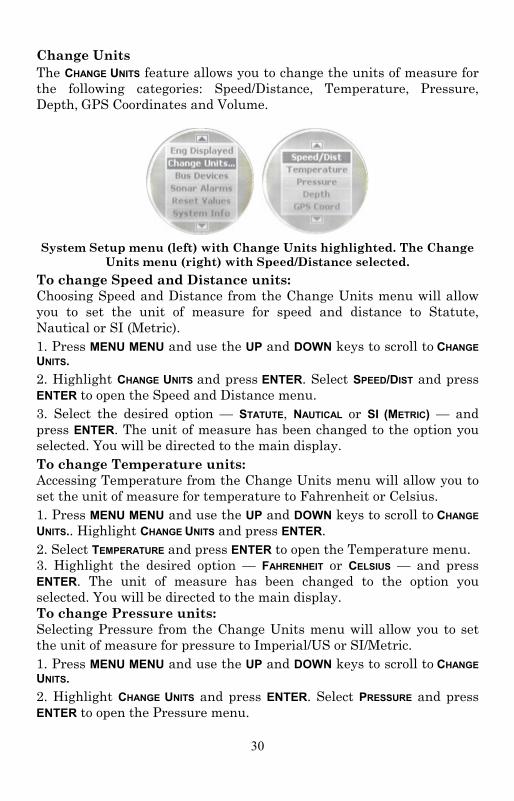
Change Units The CHANGE UNITS feature allows you to change the units of measure for the following categories: Speed/Distance, Temperature, Pressure, Depth, GPS Coordinates and Volume.
System Setup menu (left) with Change Units highlighted. The Change
Units menu (right) with Speed/Distance selected. To change Speed and Distance units: Choosing Speed and Distance from the Change Units menu will allow you to set the unit of measure for speed and distance to Statute, Nautical or SI (Metric). 1. Press MENU MENU and use the UP and DOWN keys to scroll to CHANGE UNITS. 2. Highlight CHANGE UNITS and press ENTER. Select SPEED/DIST and press ENTER to open the Speed and Distance menu. 3. Select the desired option — STATUTE, NAUTICAL or SI (METRIC) — and press ENTER. The unit of measure has been changed to the option you selected. You will be directed to the main display. To change Temperature units: Accessing Temperature from the Change Units menu will allow you to set the unit of measure for temperature to Fahrenheit or Celsius. 1. Press MENU MENU and use the UP and DOWN keys to scroll to CHANGE UNITS.. Highlight CHANGE UNITS and press ENTER. 2. Select TEMPERATURE and press ENTER to open the Temperature menu. 3. Highlight the desired option — FAHRENHEIT or CELSIUS — and press ENTER. The unit of measure has been changed to the option you selected. You will be directed to the main display. To change Pressure units: Selecting Pressure from the Change Units menu will allow you to set the unit of measure for pressure to Imperial/US or SI/Metric. 1. Press MENU MENU and use the UP and DOWN keys to scroll to CHANGE UNITS. 2. Highlight CHANGE UNITS and press ENTER. Select PRESSURE and press ENTER to open the Pressure menu.

31
3. Choose the desired option — IMPERIAL/US or SI/METRIC — and press ENTER. The unit of measure has been changed to the option you selected. You will be directed to the main display. To change Depth units: Choosing Depth from the Change Units menu will allow you to set the unit of measure for depth to Feet, Fathoms or Meters. 1. Press MENU MENU and use the UP and DOWN keys to scroll to CHANGE UNITS. 2. Highlight CHANGE UNITS and press ENTER. Select DEPTH and press ENTER to open the Depth menu. 3. Choose the desired option — FEET, FATHOMS or METERS — and press ENTER. The unit of measure has been changed to the option you selected. You will be directed to the main display. To change GPS units: Selecting GPS Coord from the Change Units menu will allow you to set the unit of measure for GPS coordinates to Deg/Min or Deg/Min/Sec. 1. Press MENU MENU and use the UP and DOWN keys to scroll to CHANGE UNITS. 2. Highlight Change Units and press ENTER. Select GPS COORD and press ENTER to open the GPS Coordinates menu. 3. Select the desired option — DEG/MIN or DEG/MIN/SEC — and press ENTER. The unit of measure has been changed to the option you selected. You will be directed to the main display. To change Volume units: Choosing Volume from the Change Units menu will allow you to set the unit of measure for volume to US Gallons or Liters. 1. Press MENU MENU and use the UP and DOWN keys to scroll to CHANGE UNITS. 2. Highlight CHANGE UNITS and press ENTER. Select VOLUME and press ENTER to open the Volume menu. 3. Select the desired option — US GALLONS or LITERS — and press ENTER. The unit of measure has been changed to the option you selected. You will be directed to the main display. Fuel Setup The following options may be accessed through the Fuel Setup menu: Refill Tank, Partial Fill, Economy Speed Source, Fuel Remaining Source, Reset Trip Fuel and Reset Seasonal Fuel. Refill Tank The Refill Tank command ensures the SMIS 4” display fuel reading is consistent with the actual amount of fuel in your tank(s). The Refill Tank command is used with the Suzuki NMEA 2000 Engine Interface.

32
The Refill Tank command is NOT used when the Fluid Level sensor is used to read the fuel level. To refill tank: 1. Press MENU MENU, and FUEL SETUP is the default location. 2. FUEL SETUP is Highlighted and you can press ENTER. 3. Select REFILL TANK and press ENTER. The select Tank menu will appear with up to three options (Port, Center and Starboard), depending on the engine-tank configuration you chose during Boat Setup. Select the tank you refilled and press ENTER. (If you have one tank, you will be taken directly to the recalibration window mentioned in step 4.)
NOTE: If a Suzuki NMEA 2000 Engine Interface is being used, a menu will appear giving you the option to calibrate fuel calculations. We will discuss calibration in Section 4: Configuration and Calibration.
4. A recalibration window will appear with two options: Yes and No. Select NO and press ENTER. The following message will appear: Press Enter after refilling the fuel tank.
NOTE: You will only recalibrate the tank when greater accuracy is necessary or when the accuracy of default settings appears to be off. We will discuss calibration in detail in Section 4: EP Configuration and Calibration.
5. Press ENTER. You will be directed back to the main display. Partial Fill Partial Fill helps maintain the accuracy of fuel used and remaining by allowing you to input the amount of fuel added to your tank(s). The Partial Fill command can be used with the Suzuki NMEA 2000 Engine Interface. The Partial Fill command is used with the Suzuki NMEA 2000 Engine Interface. It is NOT used when the Fluid Level sensor is used to read the fuel level.
NOTE: When using the Partial Fill command, you will only be able to input into the gauge, an amount of fuel less or equal to the fuel used figure. The unit will not allow you to input a fuel amount greater than the fuel used figure.
To use Partial Fill: 1. Press MENU MENU, and FUEL SETUP is the default location. FUEL SETUP is Highlighted and you can press ENTER. 2. Select PARTIAL FILL and press ENTER. The Select Tank menu will appear with up to three options (Port, Center and Starboard), depending on the engine-tank configuration you selected during Boat
33
Setup. (If you have one tank, you will be taken directly to the Adding Fuel window.) 3. Select the desired tank and press ENTER. The Adding Fuel window will appear.
NOTE: When using the Partial Fill command, you will only be able to input into the gauge, an amount of fuel less or equal to the fuel used figure. The unit will not allow you to enter a fuel amount greater than the fuel used figure.
4. Use the UP and DOWN keys to input the amount of fuel added to the tank and press ENTER. You will be taken back to the main display. Economy Speed Source The Economy Speed menu allows you to choose what speed source the SMIS 4” display will use to calculate Fuel Economy and Fuel Range. An NMEA 2000 GPS module measures ground speed, an NMEA 2000 paddlewheel measures water speed, and an NMEA 2000 Pressure Sensor measures Pitot Speed. To change Economy Speed source: 1. Press MENU MENU, and FUEL SETUP is the default location. 2. FUEL SETUP is Highlighted and you can press ENTER. Scroll to ECO SPEED SRC. 3. Highlight ECO SPEED SRC and press ENTER to open the Economy Speed menu. The menu has two options: Water Speed (Paddlewheel) and Ground Speed (GPS). 4. Select the desired speed source and press ENTER. You will be taken back to the main display. Fuel Remaining Source
The Fuel Remaining Source is set, by default, to fluid level for fuel level information.. It can also be set to Fuel Flow if desired. NOTE: If you want to use the NMEA 2000 Suzuki Engine Interface to measure fuel remaining, select Engine/FFlow from the Fuel Remaining Source menu.
To change Fuel Remaining Source: 1. Press MENU MENU, and FUEL SETUP is the default location. 2. FUEL SETUP is Highlighted and you can press ENTER. 3. Select FUEL REM SRC (Fuel Remaining Source) and press ENTER. 4. Highlight the device you want to use to measure remaining fuel — ENG/FFLOW (Engine Fuel Flow) or FLUID LEV SNSR (Fluid Level Sensor) — and press ENTER. You will be taken back to the main display.
34
Reset Trip Fuel By using the Reset Trip command, you can reset to zero the running total of fuel used on a particular trip. To reset trip fuel: 1. Press MENU MENU, and FUEL SETUP is the default location. 2. FUEL SETUP is Highlighted and you can press ENTER. 3. Highlight RST TRIP FUEL and press ENTER. The Select Engine menu will appear with up to four options (Port, Center, Starboard and All Engines), depending on the engine-tank configuration you selected during Boat Setup. (If you have one tank, the Press Enter to reset Trip Fuel message will appear.) 4. Select the desired option and press ENTER. The following message will appear: Press Enter to reset Trip Fuel. 5. Press ENTER, which will reset the trip fuel and take you back to the main display. Reset Seasonal The SMIS 4” display can keep a running total of the amount of fuel used during a season. The Resetting Seasonal fuel command resets the seasonal fuel used figure to zero. To reset seasonal fuel: 1. Press MENU MENU, and FUEL SETUP is the default location. 2. FUEL SETUP is Highlighted and you can press ENTER. 3. Select RST SEASONAL (Reset Seasonal) and press ENTER. The Select Engine menu will appear with up to four options (Port, Center, Starboard and All Engines), depending on the engine-tank configuration you chose during Boat Setup. (If you have one engine, the reset seasonal fuel message will appear.) 4. Select the desired option and press ENTER. The following message will appear: Press Enter to reset Seasonal Fuel. 5. Press ENTER to reset seasonal fuel. You will be taken back to the main display. Customizing Pages The customizing pages feature allows you to choose what data will be displayed on selected pages. Pages that can be customized include: Single Analog, Dual Analog, Quad Analog, Single Digital, Dual Digital, Quad Digital, and Fuel Manager. The Engine Trim, Engine Diagnostic, GPS Position, Trim Tab, and Synchronizer pages cannot be customized.
35
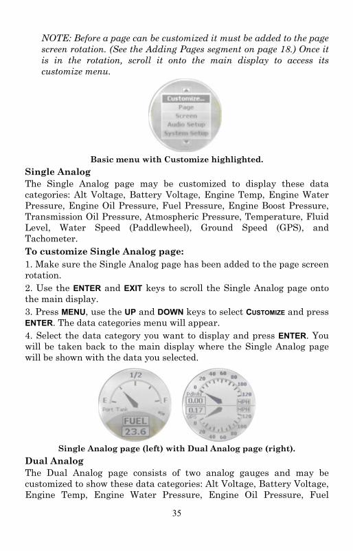
NOTE: Before a page can be customized it must be added to the page screen rotation. (See the Adding Pages segment on page 18.) Once it is in the rotation, scroll it onto the main display to access its customize menu.
Basic menu with Customize highlighted.
Single Analog The Single Analog page may be customized to display these data categories: Alt Voltage, Battery Voltage, Engine Temp, Engine Water Pressure, Engine Oil Pressure, Fuel Pressure, Engine Boost Pressure, Transmission Oil Pressure, Atmospheric Pressure, Temperature, Fluid Level, Water Speed (Paddlewheel), Ground Speed (GPS), and Tachometer. To customize Single Analog page: 1. Make sure the Single Analog page has been added to the page screen rotation. 2. Use the ENTER and EXIT keys to scroll the Single Analog page onto the main display. 3. Press MENU, use the UP and DOWN keys to select CUSTOMIZE and press ENTER. The data categories menu will appear. 4. Select the data category you want to display and press ENTER. You will be taken back to the main display where the Single Analog page will be shown with the data you selected.
Single Analog page (left) with Dual Analog page (right).
Dual Analog The Dual Analog page consists of two analog gauges and may be customized to show these data categories: Alt Voltage, Battery Voltage, Engine Temp, Engine Water Pressure, Engine Oil Pressure, Fuel
36
Pressure, Engine Boost Pressure, Transmission Oil Pressure, Atmospheric Pressure, Temperature, Fluid Level, Water Speed (Paddlewheel), Ground Speed (GPS), and Tachometer. To customize Dual Analog page: 1. Make sure the Dual Analog page has been added to the page screen rotation. 2. Use the ENTER and EXIT keys to scroll the Dual Analog page onto the main display. 3. Press MENU, use the UP and DOWN keys to select CUSTOMIZE and press ENTER. A menu will appear with two options: Top Gauge and Bottom Gauge. 4. Select the desired gauge and press ENTER. The data categories list will appear. 5. Highlight the data category you want to display and press ENTER. Repeat steps 1-5 for the other half of the page (Top Gauge or Bottom Gauge). 6. Press EXIT|EXIT to return to the main display where the Dual Analog page will be shown with the data categories you selected. Quad Analog The Quad Analog page is divided into four analog gauges, each capable of displaying these data categories: Alternator Voltage, Battery Voltage, Engine Temperature, Engine Water Pressure, Engine Oil Pressure, Fuel Pressure, Engine Boost Pressure, Transmission Oil Pressure, Atmospheric Pressure, Temperature, Fluid Level, Water Speed (Paddlewheel), Ground Speed (GPS) and Tachometer. To customize Quad Analog page: 1. Make sure the Quad Analog page has been added to the page screen rotation. 2. Use the ENTER and EXIT keys to scroll the Quad Analog page onto the main display. 3. Press MENU, select CUSTOMIZE and press ENTER. A menu will appear with four options: Top Left, Top Right, Bottom Left and Bottom Right. 4. Select the desired option and press ENTER. The data categories list will appear. 5. Highlight the data you want to display and press ENTER. Repeat steps 1-5 for each gauge (Top Left, Top Right, Bottom Left and Bottom Right). 6. Press EXIT|EXIT to get back to the Quad Analog page, where the data you selected will be displayed.
NOTE: If a page is customized to show information from a device that is working improperly or is not connected to the NMEA 2000
37
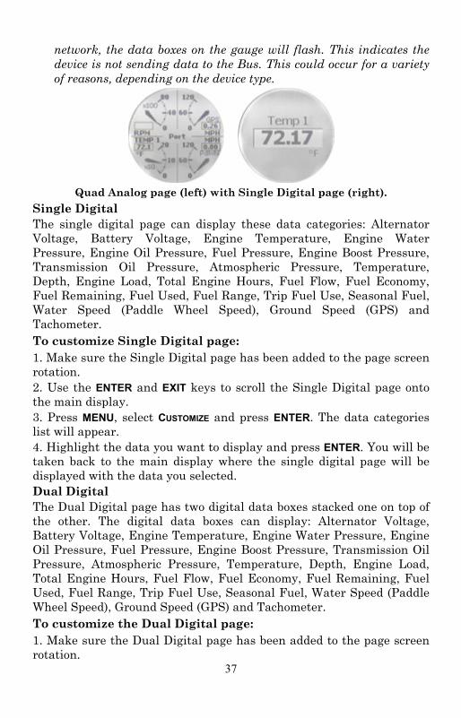
network, the data boxes on the gauge will flash. This indicates the device is not sending data to the Bus. This could occur for a variety of reasons, depending on the device type.
Quad Analog page (left) with Single Digital page (right).
Single Digital The single digital page can display these data categories: Alternator Voltage, Battery Voltage, Engine Temperature, Engine Water Pressure, Engine Oil Pressure, Fuel Pressure, Engine Boost Pressure, Transmission Oil Pressure, Atmospheric Pressure, Temperature, Depth, Engine Load, Total Engine Hours, Fuel Flow, Fuel Economy, Fuel Remaining, Fuel Used, Fuel Range, Trip Fuel Use, Seasonal Fuel, Water Speed (Paddle Wheel Speed), Ground Speed (GPS) and Tachometer. To customize Single Digital page: 1. Make sure the Single Digital page has been added to the page screen rotation. 2. Use the ENTER and EXIT keys to scroll the Single Digital page onto the main display. 3. Press MENU, select CUSTOMIZE and press ENTER. The data categories list will appear. 4. Highlight the data you want to display and press ENTER. You will be taken back to the main display where the single digital page will be displayed with the data you selected. Dual Digital The Dual Digital page has two digital data boxes stacked one on top of the other. The digital data boxes can display: Alternator Voltage, Battery Voltage, Engine Temperature, Engine Water Pressure, Engine Oil Pressure, Fuel Pressure, Engine Boost Pressure, Transmission Oil Pressure, Atmospheric Pressure, Temperature, Depth, Engine Load, Total Engine Hours, Fuel Flow, Fuel Economy, Fuel Remaining, Fuel Used, Fuel Range, Trip Fuel Use, Seasonal Fuel, Water Speed (Paddle Wheel Speed), Ground Speed (GPS) and Tachometer. To customize the Dual Digital page: 1. Make sure the Dual Digital page has been added to the page screen rotation.
38
2. Use the ENTER and EXIT keys to scroll the Dual Digital page onto the main display. 3. Press MENU, select CUSTOMIZE and press ENTER. A menu will appear with two options: Top Data and Bottom Data. 4. Highlight the desired option and press ENTER. The data categories list will appear. 5. Select the data you want to display and press ENTER. One of two things will happen, depending on the data category you selected.
1. If you chose Atmospheric Pressure, Temperature, Depth, Water Speed or Ground Speed, you will be taken back to the Top Data-Bottom Data menu. Repeat Steps 4-5 for the other uncustomized data box. 2. If you selected Alternator Voltage, Battery Voltage, Engine Temp, Engine Water Pressure, Engine Oil Pressure, Fuel Pressure, Engine Boost Pressure, Transmission Oil Pressure, Engine Load, Total Engine Hours, Fuel Flow, Fuel Economy, Fuel Remaining, Fuel Used, Fuel Range, Trip Fuel Used, Seasonal Fuel or Tachometer, you will be taken to the Select Engine menu where there will be up to three options: Port, Center and Starboard. The data category you selected will retrieve data from the engine you choose. Select the desired engine and press ENTER. You will be taken back to the Top Data-Bottom Data menu. Highlight the other uncustomized data box and repeat steps 4-5.
6. When both digital data boxes are customized, press EXIT|EXIT to return to the main display, where the dual digital page will be shown with the data you chose.
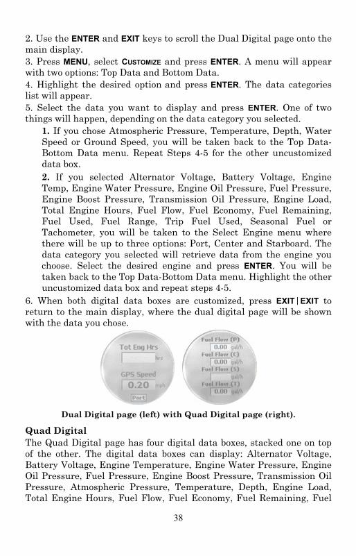
Dual Digital page (left) with Quad Digital page (right).
Quad Digital The Quad Digital page has four digital data boxes, stacked one on top of the other. The digital data boxes can display: Alternator Voltage, Battery Voltage, Engine Temperature, Engine Water Pressure, Engine Oil Pressure, Fuel Pressure, Engine Boost Pressure, Transmission Oil Pressure, Atmospheric Pressure, Temperature, Depth, Engine Load, Total Engine Hours, Fuel Flow, Fuel Economy, Fuel Remaining, Fuel

39
Used, Fuel Range, Trip Fuel Use, Seasonal Fuel, Water Speed (Paddle Wheel Speed), Ground Speed (GPS) and Tachometer. To customize Quad Digital page: 1. Make sure the Quad Digital page has been added to the page display. 2. Use the ENTER and EXIT keys to scroll the Quad Digital page onto the main display. 3. Press MENU, select CUSTOMIZE and press ENTER. The Data Box menu will appear with four options: Data Box 1, Data Box 2, Data Box 3 and Data Box 4. 4. Highlight the desired data box and press ENTER. A list of data categories will appear. 5. Select the data you want to display and press ENTER. One of two things will happen, depending on the data category you selected.
1. If you chose Atmospheric Pressure, Temperature, Depth, Water Speed or Ground Speed, you will be taken back to the Data Box menu. Repeat Steps 4-5 for the other uncustomized digital data boxes. 2. If you selected Alternator Voltage, Battery Voltage, Engine Temp, Engine Water Pressure, Engine Oil Pressure, Fuel Pressure, Engine Boost Pressure, Transmission Oil Pressure, Engine Load, Total Engine Hours, Fuel Flow, Fuel Economy, Fuel Remaining, Fuel Used, Fuel Range, Trip Fuel Used, Seasonal Fuel or Tachometer, you will be taken to the Select Engine menu which will have up to three options: Port, Center and Starboard. The data you selected will originate from the engine you choose. Select the desired engine and press ENTER. You will be taken back to the Data Box menu. Highlight the other uncustomized digital data boxes and repeat steps 4-5.
6. When all Data boxes have been customized, press EXIT|EXIT to return to the main display, where the Quad Digital page will be shown with the data you selected. Trim Tabs The Trim Tab page can display Trim Tabs position in percentages and degrees. Customize Trim Tabs: 1. Make sure the Trim Tabs page has been added to the page screen rotation. 2. Use the ENTER and EXIT keys to scroll the Trim Tabs page onto the main display.
40
3. Press MENU, select CUSTOMIZE and press ENTER. The Trim Tabs Customize menu will appear with two options: Percentage or Degrees. 4. Select the desired option and press ENTER. You will be taken back to the main display, where trim tab information will be displayed in the unit of measure you chose.
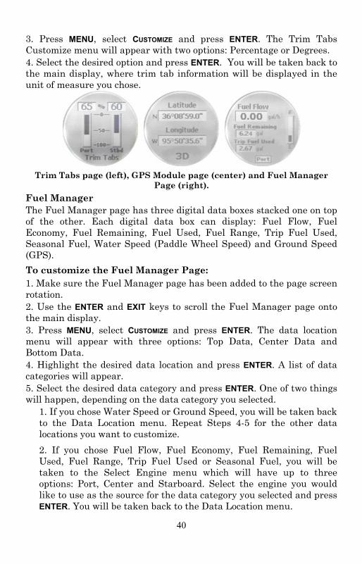
Trim Tabs page (left), GPS Module page (center) and Fuel Manager
Page (right). Fuel Manager The Fuel Manager page has three digital data boxes stacked one on top of the other. Each digital data box can display: Fuel Flow, Fuel Economy, Fuel Remaining, Fuel Used, Fuel Range, Trip Fuel Used, Seasonal Fuel, Water Speed (Paddle Wheel Speed) and Ground Speed (GPS). To customize the Fuel Manager Page: 1. Make sure the Fuel Manager page has been added to the page screen rotation. 2. Use the ENTER and EXIT keys to scroll the Fuel Manager page onto the main display. 3. Press MENU, select CUSTOMIZE and press ENTER. The data location menu will appear with three options: Top Data, Center Data and Bottom Data. 4. Highlight the desired data location and press ENTER. A list of data categories will appear. 5. Select the desired data category and press ENTER. One of two things will happen, depending on the data category you selected.
1. If you chose Water Speed or Ground Speed, you will be taken back to the Data Location menu. Repeat Steps 4-5 for the other data locations you want to customize. 2. If you chose Fuel Flow, Fuel Economy, Fuel Remaining, Fuel Used, Fuel Range, Trip Fuel Used or Seasonal Fuel, you will be taken to the Select Engine menu which will have up to three options: Port, Center and Starboard. Select the engine you would like to use as the source for the data category you selected and press ENTER. You will be taken back to the Data Location menu.

41
6. Repeat Steps 4 and 5 for each of the other data locations you want to customize. When all have been customized, press EXIT|EXIT to get back to the Fuel Manager page.
42
Section 4: Electronic Sensor Configuration & Calibration
To configure items connected to the network, press MENU MENU, scroll to BUS DEVICES and press ENTER to open the Bus Devices list. A list of devices on the network will appear. Bus Devices works as the device manager for the bus, allowing you to configure and unconfigure devices and set and reset critical values such as alarms and calibration. When you configure or reconfigure a sensor, you are assigning or reassigning its configuration name in the SMIS 4” display to a different sensor location on the boat.
NOTE: The Temperature sensor and Fluid Level are the only sensors that can be configured.
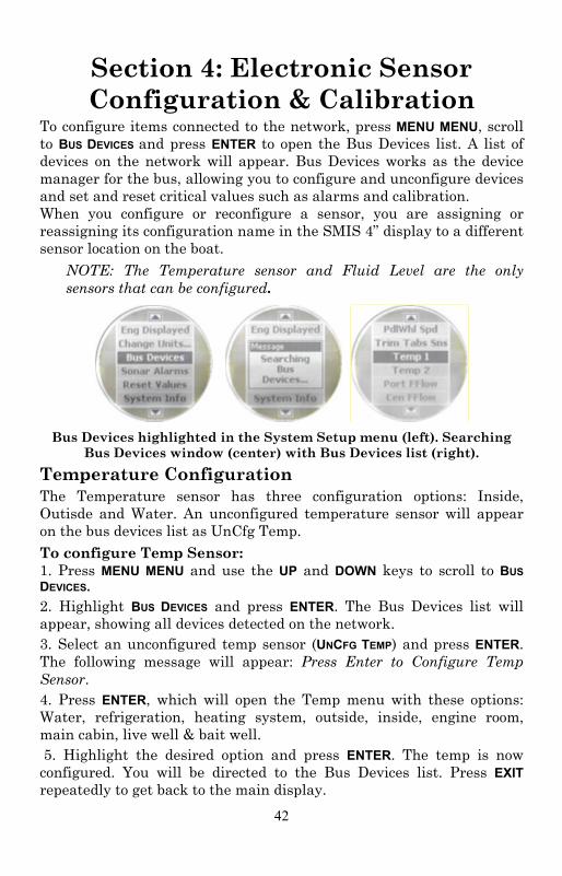
Bus Devices highlighted in the System Setup menu (left). Searching
Bus Devices window (center) with Bus Devices list (right). Temperature Configuration The Temperature sensor has three configuration options: Inside, Outisde and Water. An unconfigured temperature sensor will appear on the bus devices list as UnCfg Temp. To configure Temp Sensor: 1. Press MENU MENU and use the UP and DOWN keys to scroll to BUS DEVICES. 2. Highlight BUS DEVICES and press ENTER. The Bus Devices list will appear, showing all devices detected on the network. 3. Select an unconfigured temp sensor (UNCFG TEMP) and press ENTER. The following message will appear: Press Enter to Configure Temp Sensor. 4. Press ENTER, which will open the Temp menu with these options: Water, refrigeration, heating system, outside, inside, engine room, main cabin, live well & bait well. 5. Highlight the desired option and press ENTER. The temp is now configured. You will be directed to the Bus Devices list. Press EXIT repeatedly to get back to the main display.
43
To unconfigure an temp sensor: 1. Press MENU MENU and use the UP and DOWN keys to scroll to BUS DEVICES. 2. Highlight BUS DEVICES and press ENTER. The Bus Devices list will appear, showing all devices detected on the network. 3. Choose the temp sensor you want to unconfigure and press ENTER. Select UNCONFIGURE from the temp configuration menu and press ENTER. The following message will appear: Press Menu to UnConfig Device Name. 4. Press ENTER to unconfigure the sensor and be directed back to the Bus Devices list where the temp now will be listed as UnCfg Temp. To reconfigure an temp sensor: To reconfigure a sensor, there must be a configuration name available (Water, Outside or Inside). If all three temp sensors have been configured, you first will have to unconfigure a temp sensor to make its name available for reconfiguration. If you try to reconfigure a sensor when the desired configuration name (Water, Outside and Inside) is in use, a Name Already Selected message will appear. If all three temps are configured, which means there is no name configuration available, follow the first set of instructions. If the desired configuration name is available, follow the second set of instructions. The steps below will show you how to switch the configuration of a water temp to an outside temp. If all temps configured (Configuration name unavailable): 1. Press MENU MENU and use the UP and DOWN keys to scroll to BUS DEVICES. 2. Highlight BUS DEVICES and press ENTER. Select OUT: T (Outside Temp) and press ENTER to open the temp configuration menu. 3. Select UNCONFIGURE and press ENTER. The following message will pop up: Press Enter to UnConfig Device Name. 4. Press ENTER to unconfigure the sensor and be taken back to the Bus Devices list. The Outside temp is now unconfigured and will be displayed as UnCfg Temp. Its configuration name (Outside) is now available, so you will be able to use it to reconfigure the Water temp sensor. 5. Highlight WTR: T and press ENTER, which will open the temp configuration menu. Select RECONFIGURE and press ENTER. That will direct you to the Temp Selection menu. Scroll to your choice of remaining temperature designations.
44
6. Select OUTSIDE and press ENTER. You will be taken back to the Bus Devices list. The temp you just reconfigured (formerly water temp) will now be displayed as Out: T 7. To configure the unconfigured Temp (formerly Outside temp), highlight UNCFG TEMP from the Bus Devices list and press ENTER to open the Temp Selection menu, and make your choice. Highlight WATER and press ENTER. You will be taken back to the Bus Devices list, where the temp you just configured will be displayed as WTR: T. If desired configuration name available: 1. Press MENU MENU and use the UP and DOWN keys to scroll to BUS DEVICES. 2. Highlight BUS DEVICES and press ENTER. Select WTR: T and press ENTER to open the configuration options menu. 3. Select RECONFIGURE and press ENTER to open the Temp Selection menu, which will have three options: Water, Outside and Inside. 4. Highlight OUTSIDE and press ENTER. You will be taken back to the Bus Devices list where the temp will now be shown as Out T. Calibrating Fuel Flow in an Engine Interface The default calibration for a Suzuki Engine Interface is adequate in most cases, but if fuel used readings are off by more than 3 percent, calibration is recommended. NOTE:
Make sure the fuel flow has been set as the Fuel Remaining Source; otherwise, you will not be able to calibrate the engine interface.
Engine Interface Accuracy To check the accuracy of an engine interface, add the Fuel Manager page to the page screen rotation then customize it to show Fuel Used data. To check engine adapter accuracy: 1. Fill up the tank connected to engine that is attached to your engine interface. 2. Press MENU MENU, and FUEL SETUP is the default location. 3. FUEL SETUP is Highlighted and you can press ENTER. 4. Select REFILL TANK and press ENTER. If your unit is configured for more than one tank, the Select Tank menu will open with up to three options: Port, Center and Starboard. (If your vessel is configured for one engine, you will be directed to the recalibration menu.)
45
5. Select the tank you refilled and press ENTER. The Recalibration menu will appear with two options: Yes and No. Select NO and press ENTER. The following message will appear: Press Enter after refilling the fuel tank. Press ENTER. 6. Take your boat out, but run only ONE engine — the engine connected to the engine interface. Burn at least 5 gallons of fuel, then fill up the tank again, noting how much fuel was added to the tank. Check the Fuel Manager page for the fuel used figure calculated by engine interface. 7. Compare the amount of fuel added when you filled up the tank with the Fuel Used figure shown on your gauge. If the difference between these two numbers is greater than 3 percent, you need to calibrate the unit. To calibrate an engine interface: 8. Fill up the fuel tank connected to the engine that is attached to your engine interface. 9. Press MENU MENU, and FUEL SETUP is the default location. 10. FUEL SETUP is Highlighted and you can press ENTER. 11. Select REFILL TANK and press ENTER. If your unit is configured for more than one tank, the Select Tank menu will open with up to three options: Port, Center and Starboard. (If your vessel is configured for one engine, you will be directed to the recalibration menu.) Select the tank you refilled and press ENTER. 12. The Recalibration menu will appear with two options: Yes and No. Select YES and press ENTER. 13. The Filled Quantity window will appear. Use the UP and DOWN keys to input the amount of fuel you added to the tank and press ENTER. 14. Repeat these steps for each engine interface you want to calibrate. Calibrating Engine Trim You must add the Engine Trim page to the main display before you will be able to proceed with engine trim calibration. NOTE:
You will not use the engine trim feature with DF300 engines of any year, 2009 DF70/80/90 engines, or 2010 DF60/70/80/90 engines.
To calibrate Engine Trim: 1. Use the ENTER and EXIT keys to scroll the Engine Trim on to the main display. Press MENU. 2. Highlight TRIM CAL and press ENTER. The Select Engine menu will
46
appear with up to three options: Port, Center and Starboard. (If you selected a single-engine tank configuration you will be taken to the engine's Trim Calibration menu.) 3. Select the engine connected to the engine interface and press ENTER. The engine's Trim Calibration menu will appear with two options: Lower Limit and Upper Limit. 4. Select LOWER LIMIT and press ENTER. The following Trim Cal message will appear: Set Engine All Down and Press Enter. Put your engine in the full down position, then press ENTER. 5. Highlight UPPER LIMIT and press ENTER. The following Trim Cal message will appear: Set Engine All Up and Press Enter. Put your engine in the full up position, then press ENTER. Press EXIT repeatedly to return to the main display. Reset Calibration The Reset Fuel Calibration command allows you to reset engine interface fuel calibration back to default settings. The Reset Trim Calibration command allows you to set engine interface engine trim calibration settings back to default settings. To reset fuel calibration: 1. Press MENU MENU and use the UP and DOWN keys to scroll to BUS DEVICES. 2. Highlight BUS DEVICES and press ENTER. Highlight the engine connected to the engine interface you want to reset and press ENTER. 3. Select RST FUEL CAL from the engine interface menu and press ENTER. The following message will appear: Press Enter to reset the Fuel Cal. 4. Press ENTER to set calibration back to default settings. To recalibrate the engine interface, follow the steps in the previous segment regarding engine interface calibration. To reset engine trim calibration: 1. Press MENU MENU and use the UP and DOWN keys to scroll to BUS DEVICES. 2. Highlight BUS DEVICES and press ENTER. Highlight the engine connected to the engine interface you want to reset and press ENTER. 3. Select RST TRIM CAL from the engine interface menu and press ENTER. The following message will appear: Press Enter to reset the Trim Cal. 4. Press ENTER to set calibration back to default settings. To recalibrate the engine interface, follow the steps in the previous segment covering engine interface calibration.
47
Fluid Level Configuration The SMIS 4” display will support up to three tanks for each Fluid Level type which includes: Fuel, Fresh Water, Oil, Black Water, Waste Water (Gray Water) and Live Well. On the Bus Devices list, the fuel tanks will be displayed as Fuel Tank (P) — Portside, Fuel Tank (C) — Center, and Fuel Tank (S) —Starboard. If you chose a one-tank configuration in Boat Setup, the tank will be listed as Fuel Tank. Like a fuel tank, the Oil Tank will also be appended with its engine location — Oil Tank (P), Oil Tank (C) or Oil Tank (S). When setting fluid level configuration for the other fluid types you will be given the opportunity to assign the tank a number in case you have more than one tank of that fluid type. The tanks will be appended with a tank number of your choosing. By default, the tank number is set to 1. The other fluid types will be displayed as BlkWtr Tnk (1, 2 or 3), FrshWtr Tnk (1, 2 or 3), LWell Tnk (1, 2 or 3) and WsteWtr Tnk (1, 2 or 3). If the fluid level has not been configured, it will be listed as Unfcg F Lev on the bus devices list.
NOTE: The Fuel Remaining Source must be set to fluid level for the unit to correctly display fuel level information. It is set to Engine/Fuel Flow by default.
Fluid Level menu The Fluid Level menu contains the following features: Configure, Unconfigure, Reconfigure, Level Warning, Calibrate, Reset Calibration and Reset Values. Calibration and Reset Calibration will be addressed in the calibration portion of this section.
NOTE: If you select fuel remaining source as fluid level you will NOT be able to get a fuel range reading. Fuel Range will NOT be calculated with a fluid level sensor. It will only be calculated with an engine interface.
To configure Fluid Level sensor for Fuel: 1. Make sure the Fuel Remaining Source has been set to Fluid Level. Press MENU MENU and use the UP and DOWN keys to scroll to BUS DEVICES. 2. Highlight BUS DEVICES and press ENTER to bring up the Bus Devices list. 3. Select UNFCG F LEV and press ENTER. The following message will appear: Press Enter to configure Fluid Lev Snsr. 4. Press ENTER and the Fluid Level configuration menu will appear.
48
5. Choose FUEL and press ENTER, which will open the Select Tank menu with up to three options: Port Tank, Center Tank and Starboard Tank. The number of tank options depends on the engine-tank configuration you chose during Boat Setup. 6. Select the tank connected to the fluid level you are configuring and press ENTER. You will be taken back to the Bus Devices list, where the tank will be displayed as Fuel Tank (P), Fuel Tank (C) or Fuel Tank (S). Press EXIT repeatedly to return to the main display. To configure for Fresh Water: 1. Press MENU MENU and use the UP and DOWN keys to scroll to BUS DEVICES. 2. Highlight BUS DEVICES and press ENTER. The Bus Devices list will appear. 3. Select UNFCG F LEV and press ENTER. The following message will appear: Press Enter to configure Fluid Lev Snsr. Press ENTER and the Fluid Level configuration menu will appear. 4. Choose FRESH WATER and press ENTER. The Tank Number window will appear. 5. Use the UP and DOWN keys to input the number you want to assign the tank and press ENTER. The Setting Tank Size window will appear on the screen. 6. Use the UP and DOWN keys to input the size of the tank and press ENTER. You will be taken back to the Bus Devices list, where the tank will be displayed as FrshWtr Tnk (1, 2 or 3). To configure for Waste Water (Gray Water): 1. Press MENU MENU and use the UP and DOWN keys to scroll to BUS DEVICES. 2. Highlight BUS DEVICES and press ENTER. The Bus Devices list will appear. 3. Select UNFCG F LEV and press ENTER. The following message will appear: Press Enter to configure Fluid Lev Snsr. Press ENTER and the Fluid Level configuration menu will appear. 4. Choose WASTE WATER and press ENTER. The Tank Number window will appear. 5. Use the UP and DOWN keys to input the number you want to assign the tank and press ENTER. The Setting Tank Size window will appear on the screen. 6. Use the UP and DOWN keys to input the size of the tank and press ENTER. You will be taken back to the Bus Devices list, where the tank will be displayed as WstWtr Tnk (1, 2 or 3). Press EXIT repeatedly to get back to the main display.
49
To configure for Live Well: 1. Press MENU MENU and use the UP and DOWN keys to scroll to BUS DEVICES. 2. Highlight BUS DEVICES and press ENTER. The Bus Devices list will appear. 3. Select UNFCG F LEV and press ENTER. The following message will appear: Press Enter to configure Fluid Lev Snsr. Press ENTER and the Fluid Level configuration menu will appear. 4. Choose LIVE WELL and press ENTER. The Tank Number window will appear. 5. Use the UP and DOWN keys to input the number you want to assign the tank and press ENTER. The Setting Tank Size window will appear on the screen. 6. Use the UP and DOWN keys to input the size of the tank and press ENTER. You will be taken back to the Bus Devices list, where the tank will be displayed as LWell Tnk (1, 2 or 3). To configure for Oil: 1. Press MENU MENU and use the UP and DOWN keys to scroll to BUS DEVICES. 2. Highlight BUS DEVICES and press ENTER. The Bus Devices list will appear. 3. Select UNFCG F LEV and press ENTER. The following message will appear: Press Enter to configure Fluid Lev Snsr. 4. Press ENTER and the Fluid Level configuration menu will appear. 5. Choose OIL and press ENTER, which will open the Select Tank menu with up to three options: Port Tank, Cen Tank and Stbd Tank. The number of tank options depends on the number of tanks you chose during Boat Setup. 6. Select the desired tank and press ENTER. 7. The Tank Size window will appear. Use the UP and DOWN keys to input the size of the tank and press ENTER. You will be taken back to the Bus Devices list, where the tank will be displayed as Oil Tank (P), Oil Tank (C) or Oil Tank (S). To configure for Black Water: 1. Press MENU MENU and use the UP and DOWN keys to scroll to BUS DEVICES. 2. Highlight BUS DEVICES and press ENTER. The Bus Devices list will appear.
50
3. Select UNFCG F LEV and press ENTER. The following message will appear: Press Enter to configure Fluid Lev Snsr. Press ENTER and the Fluid Level configuration menu will appear. 4. Choose BLACK WATER and press ENTER. The Tank Number window will appear. 5. Use the UP and DOWN keys to input the number you want to assign to the tank and press ENTER. The Setting Tank Size window will appear on the screen. 6. Use the UP and DOWN keys to input the size of the tank and press ENTER. You will be taken back to the Bus Devices list, where the tank will be displayed as BlkWtr Tnk (1, 2 or 3). To unconfigure Fluid Level: 1. Press MENU MENU and use the UP and DOWN keys to scroll to BUS DEVICES. 2. Highlight BUS DEVICES and press ENTER, which will open the Bus Devices list. 3. Choose a configured Fluid Level from the Bus Devices list and press ENTER. The Fluid Level will appear with the following options: Level Warning, Unconfigure, Reconfigure, Calibrate, Reset Cal and Reset Values. 4. Highlight UNCONFIGURE and press ENTER, which will launch the following message: Press Enter to Unconfig Device name. 5. Press ENTER and you will be taken back to the Bus Devices list where the fluid level you unconfigured will be displayed as UnCfg F Level. To reconfigure Fluid Level: 1. Press MENU MENU and use the UP and DOWN keys to scroll to BUS DEVICES. 2. Highlight BUS DEVICES and press ENTER. The Bus Devices list will appear. 3. Select the Fluid Level you want to configure and press ENTER. 4. The Fluid Level menu will appear with the following options: Level Warning, Unconfigure, Reconfigure, Calibrate, Reset Cal and Reset Values. 5. Choose RECONFIGURE and press ENTER. Use the UP and DOWN keys to input the tank number you want to assign the fluid level and press ENTER. The Setting Tank Size window will appear on the screen. 6. Use the UP and DOWN keys to input the size of the tank and press ENTER. You will be taken back to the Bus Devices list, where the fluid level will be displayed with its new configuration.
51
Level Warning A Level Warning alerts you when the fluid level rises above or falls below a preset percentage of tank capacity. The Level Warning menu has two options: Low Level and High Level. A low level warning is used for fluid types like fuel and freshwater, whereas a high level warning is best suited for black water and Waste Water (Gray Water). To set a Level Warning: 1. Press MENU MENU and use the UP and DOWN keys to scroll to BUS DEVICES. 2. Highlight BUS DEVICES and press ENTER. The Bus Devices list will appear. 3. Select the desired fluid level and press ENTER. 4. Choose LEVEL WRNG and press ENTER. The Level Warning menu will appear with two options: Low Level and High Level. 5. Select the desired alarm level and press ENTER. The Set Level Percentage window will appear. By default, it will be set to Off. (You can turn off a level warning by setting the Set Level percentage window to Off.) 6. Use the UP and DOWN keys to set the alarm to the desired percentage of tank capacity. Press ENTER. You will be taken back to the Bus Devices list. Press EXIT repeatedly to get back to the main display.
NOTE: If you configure a tank for fuel, you should choose a LOW
LEVEL warning, which will warn you when the fuel level drops below a preset percentage of the tank's capacity. A Low Level alarm will also work best for Fresh Water and Oil configurations. When a tank is configured for Black Water or Waste Water, the Level Warning should be set to the High Level. If, for example, you set the High Level warning to 3 quarters of a tank, you would be alerted before the tank's capacity had been exceeded, allowing you to empty the tanks before they fill up.
Reset Values Accessing the Reset Values command from the Fluid Level menu, allows you to reset the values of an individual fluid level without affecting the settings of any other sensor. To Reset Values: 1. Press MENU MENU and use the UP and DOWN keys to scroll to BUS DEVICES. 2. Highlight BUS DEVICES and press ENTER. The Bus Devices list will appear.
52
4. Select the fluid level you want to reset and press ENTER. The Fluid Level menu will appear with the following options: Level Warning, Unconfigure, Reconfigure, Calibrate, Reset Cal and Reset Values. 5. Choose RESET VALUES and press ENTER. The following message will appear: Press Enter to Reset Device Values. 6. Press ENTER to reset the fluid level's settings back to factory defaults.
NOTE: If you reset values from a fluid level menu, you will only restore default settings for that particular fluid level sensor. Executing the Reset Values command will also clear configuration and calibration settings.
Calibrating Electronic Sensors The default calibration for the Fluid Level is for the standard US marine fluid level senders and is as accurate as standard fluid level gauges. If, however, the tank has an irregular shape or greater accuracy is needed, calibration is recommended. Calibrating Fluid Level The Fluid Level has three calibration options: 2 point, 3 point and 5 point. 2-Point Calibration A 2-point calibration is best suited for rectangular or square-shaped tanks, where the capacity of the top half of the tank matches the capacity in the lower half of the tank. In a two-point calibration, you will set two points, one each for empty and full levels. You can begin calibration at either of the two points, but we recommend starting with an empty tank. You will fill the tank to complete calibration. To execute 2-Point calibration: 1. Before following the steps below, make sure your fuel tank is empty. 2. Press MENU MENU and use the UP and DOWN keys to scroll to BUS DEVICES. 3. Highlight BUS DEVICES and press ENTER. Chose the fluid level you want to calibrate and press ENTER. 4. Select CALIBRATE and press ENTER. The Number of Points menu will appear with three options: 2, 3 and 5. Select 2, for two-point calibration, and press ENTER. 5. The Levels menu will appear with two choices: Empty Level and Full Level. Choose EMPTY LEVEL and press ENTER. 6. The following message will appear: Set Tank to Empty Level Press Enter. Press ENTER. You will be taken back to the Levels menu. 7. Fill up your tank.
53
8. Select FULL LEVEL and press ENTER. The following message will appear: Set Tank to Full Level Press Enter. 9. Press ENTER. Press EXIT repeatedly to return to the main display. 3-Point Calibration 3-point calibration is designed for tanks that vary in shape from the top to the bottom. You can begin calibration at any point in the 3-point process, but we recommend starting calibration with an empty tank. In a 3-point calibration, you will set three points, one each for empty, half and full levels. To execute 3-Point calibration: 1. Before following the steps below, make sure your fuel tank is empty. 2. Press MENU MENU and use the UP and DOWN keys to scroll to BUS DEVICES. 3. Highlight BUS DEVICES and press ENTER. Chose the fluid level you want to calibrate and press ENTER. 4. Select CALIBRATE and press ENTER. The Number of Points menu will appear with three options: 2, 3 and 5. Select 3, for three-point calibration, and press ENTER. 5. Highlight EMPTY LEVEL and press ENTER. The following message will appear: Set Tank to Empty Level Press Enter. 6. Press ENTER. You will be taken back to the Levels menu. 7. Add half a tank of fuel. (If you had a 100 gallon tank, you would add 50 gallons.) 8. Select HALF LEVEL and press ENTER. The following message will appear: Set Tank to Half Level Press Enter. 9. Press ENTER. You will be taken back to the Levels menu. 10. Fill up your tank. 11. Highlight FULL LEVEL and press ENTER. The following message will appear: Set Tank to Full Level Press Enter. 12. Press ENTER. You will be taken back to the Levels menu. Press EXIT repeatedly to get back to the main display. 5-Point Calibration 5-point calibration is best suited tanks that vary greatly in shape from top to bottom. You can begin calibration at any point in the 5-point calibration process. We recommend starting calibration with an empty tank. In a five-point calibration you will set five points: Empty Level, 1 Qtr Level, Half Level, 3 Qtr Level and Full Level.’
54
To execute 5-Point calibration: 1. Press MENU MENU and use the UP and DOWN keys to scroll to BUS DEVICES. 2. Highlight BUS DEVICES and press ENTER. Chose the fluid level you want to calibrate and press ENTER. Select CALIBRATE and press ENTER. The Number of Points menu will appear with three options: 2, 3 and 5. Select 5, for three-point calibration, and press ENTER. 3. The Levels menu will appear with five options: Empty Level, 1 Qtr Level, Half Level, 3 Qtr Level and Full level. Select EMPTY LEVEL and press ENTER. The following message will appear: Set Tank to Empty Level Press Enter. 4. Press ENTER. You will be taken back to the Levels menu. Add 1-quarter tank of fuel. (If you have a 100 gallon tank, add 25 gallons of fuel.) 5. Highlight 1 QTR LEVEL and press ENTER. The following message will appear: Set Tank to 1 Qtr Level Press Enter. 6. Press ENTER. You will be taken back to the Levels menu. Fill your tank up halfway. (If you have a 100 gallon tank, add another 25 gallons of fuel.) 7. Highlight HALF LEVEL and press ENTER. The following message will appear: Set Tank to Half Level Press Enter. Press ENTER. You will be taken back to the Levels menu. 8. Fill your tank to the 3 quarter level. (If you have a 100 gallon tank, add another 25 gallons of fuel.) Highlight 3 QTR LEVEL and press ENTER. The following message will appear: Set Tank to 3 Qtr Level Press Enter. 9. Press ENTER. You will be taken back to the Levels menu. Fill up your tank, then select FULL LEVEL and press ENTER. The following message will appear: Set Tank to Full Level Press Enter. 10. Press ENTER. You will be taken back to the Levels menu. Press EXIT repeatedly to get back to the main display. Reset Calibration The Reset Calibration command allows you to reset a fuel flow back to factory default settings. You will only need to reset calibration when you believe your fuel flow has been calibrated incorrectly. To Reset Calibration: 1. Press MENU MENU and use the UP and DOWN keys to scroll to BUS DEVICES. 2. Highlight BUS DEVICES and press ENTER. Chose the fluid level you want to calibrate and press ENTER.
55
3. Highlight RESET CAL from the fluid level menu and press ENTER. The following message will appear: Press Enter to reset Calibration. 4. Press ENTER to set calibration back to factory default settings. You, then, will be returned to the bus devices list.
NOTE: If you have calibrated your fluid level sensor and are having problems with the sensor's performance, be sure to check the sending unit. You can do this by using an ohm meter to test the resistance of the unit. Connect the sending unit pink wire and the ship or sending unit ground wire to the ohm meter. With the tank full, the resistance should be 33-1/2 ohms. When the tank is the empty, the resistance should be 240 ohms. If, when the tank is full or empty, the ohm readings are significantly different from the standard full (33-1/2) and empty (240) ohms levels, there is a problem with the sending unit. If the ohm readings are the same in both cases, the sending unit is stuck.
Pressure Sensor Calibration The Pressure Sensor can only be calibrated when it is configured as a pitot speed sensor. The speed needs to be able to be calibrated because different boat hull designs create different pressure readings by the pitot tube. The speed is calibrated up or down by percentage points. The default is 0%. Calibrating Trim Tabs Trim Tabs are calibrated though the Trim Tab pages menu. If the Trim Tab page is not displayed in the page screen rotation, refer to Section 2: Operation section for information on how to add the Trim Tab page to the page screen rotation. To calibrate Trim Tabs: 1. Make sure the Trim Tabs page is on the main display 2. Press MENU, select CALIBRATE TAB and press ENTER. The following message will appear: Bring Tabs Full Up Press Enter. 3. Adjust the position of the Trim Tabs to the Full Up Position and press ENTER. A second message will appear: Run Tabs Full DN (Down). 4. Move the Trim Tabs into the full down position. The Trim Tabs are now calibrated. You will be taken back to the main display.

56
Trim Tabs menu (left). When calibrating Trim Tabs, the Full Up
message (center) appears first. It is followed by the Run Tabs Full Down message (right).
57
How to Obtain Service… …in the USA: Contact your nearest Suzuki Marine Dealer …in Canada: Contact your nearest Suzuki Marine Dealer …outside Canada and the USA: Contact the dealer in the country where you purchased your unit.
Accessory Ordering Information Please contact your local Suzuki Marine dealer. To locate a Suzuki Marine dealer, visit the web site, www.suzukimarine.com, and look for the Dealer Locator. To locate a Canadian Suzuki Marine dealer, visit the web site, http://www.suzuki.ca, and look for the Dealer Locator. Or, consult your telephone directory for listings.

58
© Copyright 2009 All Rights Reserved American Suzuki Motor Corp. *988-0151-38B*