techinical specifications
TRANSCRIPT
TECHINICAL SPECIFICATIONS
GROUP A
1. 9 Mtr 300Kg long PSC Pole 2. 8 Mtr long PSC Pole
GROUP B
3 11KV F Clamp
4 11 KV 'V' Cross Arm
5 Back Clamp for 'V'
6 11 KV GI Pin
7 11KV T&C H.W Fitting
8 20mm HT Stay Set
9 7/10 SWG GI Stay Wire
10 7/12 SWG GI Stay Wire
11 HT Stay Clamps
12 Pipe Earthing ( 40 mm Dia)
13 Earthing coil
14 Cable socket for 35mm² Cable
15 Cable socket for 95mm² Cable
16 Cable Socket for 120mm²
17 Suspension Clamps
18 Dead End Clamps
19 Pole clamp with Eye hook
20 16mm LT Stay Set
21 LT Stay Clamp
22 Pearcing connector
23 Neutral connector
24 Danger Board
25 Barbed Wire
26 No SWG 6 GI wire
27 No SWG 8 GI wire
28 11KV 120mm2 3 Core O/D type end Jointing Kit
GROUP C 29 11 KV Pin Insulator
30 11KV T&C Disc Insulator
31 HT Stay Insulator
32 LT Stay Insulator
GROUP D
33 35mm2 Single Core XLPE Cable
34 95mm2 Single Core LT XLPE Cable
35 120mm2 Single Core LT XLPE Cable 36 11KV 120mm2 3-Core XLPE insulated overhead Cable
GROUP A
TECHNICAL SPECIFICATION OF
1. 8MTR 200KG PSC POLE
2. 9MTR 300KG PSC POLE
TECHNICAL SPECIFICATIONS
Applicable Standard: The Poles shall comply with latest standards as under: REC Specification No. 15/1979, REC Specification No. 24/1983, IS 1678, IS 2905, IS 7321.
II. Materials:
Cement: Cement to be used in the manufacture of pre-stressed concrete poles shall be ordinary for rapid hardening Portland cement confirming to IS: 269-1976 (Specification for ordinary and low heat Portland cement) or IS: 8041 E-1978 (Specification for rapid hardening Portland cement).
Aggregates: Aggregates to be used for the manufacture of pre-stressed concrete poles shall confirm
to IS:383 (Specification for coarse and fine aggregates from natural sources for concrete) The
nominal maximum sizes of aggregates shall in no case exceed 12 mm.
Water: Water should be free from chlorides, sulphates, other salts and organic matter. Potable
water will be generally suitable.
Admixture: Admixture should not contain Calcium Chloride or other chlorides and salts which are likely
to promote corrosion of pre-stressing steel. The admixture shall conform to IS: 9103.
Pres-Stressing Steel: Pre-stressing steel wires including those used as un tensioned wires should
conform to IS:1785 (Part-I) (Specification for plain hard-drawn steel wire for pre-stressed concrete,
Part-I cold drawn stress relieved wire).IS:1785 (Part-II)(Specification for plain hard-drawn steel wire)
or IS:6003 (Specification for indented wire for pre-stressed concrete).The type design given in the
annexure are for plain wires of 4 mm diameter with a guaranteed ultimate strength of 160
kg/mm². All pre-stressing steel shall be free from splits, harmful scratches, surface flaw, rough, aged
and imperfect edges and other defects likely to impair its use in pre-stressed concrete.
Concrete Mix: Concrete mix shall be designed to the requirements laid down for controlled
concrete (also called design mix concrete) in IS: 1343-1980 (Code of practice for pre-stressed
concrete) and IS: 456 – 1978 (Code of practice for plain and reinforced concrete) subject to the
following special conditions:
Minimum works cube strength at 28 days should be at least 420 Kg/cm². The concrete strength at
transfer should be at least 210 Kg/cm².
The mix should contain at least 380 Kg of cement per cubic meter of concrete.
The mix should contain as low water content as is consistent with adequate workability.
It becomes necessary to add water to increase the workability the cement content also should be
raised in such a way that the original value of water cement ratio is maintained.
III. Design Requirements
The poles shall be designed for the following requirements:
The poles shall be planted directly in the ground with a planting depth as per IS: 1678.
Wherever, planting depth is required to be increased beyond the specified limits or alternative
arrangements are required to be made on account of ground conditions e.g. water logging etc., the
same shall be in the scope of the bidder at no extra cost to owner. The bidder shall furnish necessary
design calculations/details of alternative arrangements in this regard.
The working load on the poles should correspond to those that are likely to come on the pole during
their service life.
The factor of safety for all poles 9.0Mts. Shall not be less than 2.0 and for 8.0 M poles, the factor
of safety shall not be less than 2.5.
The average permanent load shall be 40% of the working load.
The F.O.S. against first load shall be 1.0.
At average permanent load, permissible tensile stress in concrete shall be 30 kg/cm². At the design
value of first crack load, the modulus of rupture shall not exceed 53.0kg/cm² for M-40.
The ultimate moment capacity in the longitudinal direction should be at least one fourth of that in the
transverse direction.
The maximum compressive stress in concrete at the time of transfer of pre-stress should not
exceed 0.8 times the cube strength.
The concrete strength at transfer shall not be less than half, the 28 days strength ensured in the
design, i.e. 420x0.5=210kg/cm². For model check calculations on the design of poles, referred to in
the annexure, a reference may be made to the REC ―Manual on Manufacturing of solid PCC poles,
Part-I-Design Aspects‖.
IV. Dimensions and Reinforcement
The cross-sectional dimensions and the details of pre-stressing wires should conform to the
particulars given in the enclosed drawing. The provisions of holes for fixing cross-arms and other
fixtures should conform to the REC specification No.15/1979.
All pre-stressing wires and reinforcements shall be accurately fixed as shown in drawings and
maintained in position during manufacture. The un-tensioned reinforcement as indicated in the
drawings should be held in position by the use of stirrups which should go round all the wires.
All wires shall be accurately stretched with uniform pre-stressed in each wire. Each wire or group of
wires shall be anchored positively during casing. Care should be taken to see that the anchorages do
not yield before the concrete attains the necessary strength.
V. Cover
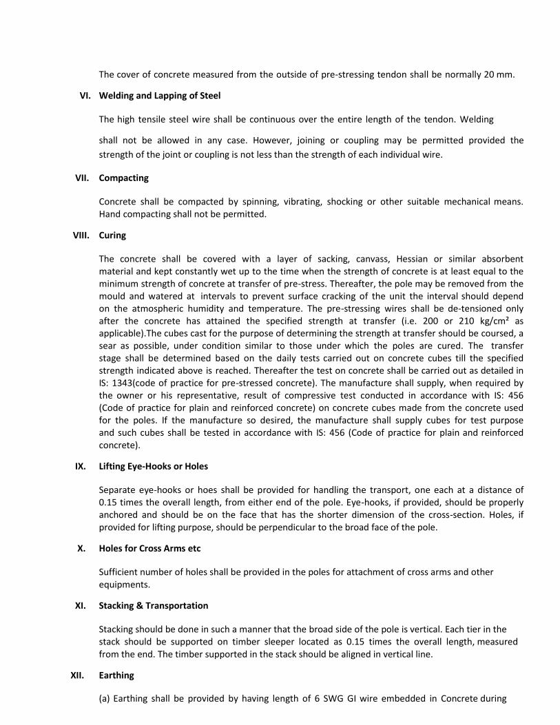
The cover of concrete measured from the outside of pre-stressing tendon shall be normally 20 mm.
VI. Welding and Lapping of Steel
The high tensile steel wire shall be continuous over the entire length of the tendon. Welding
shall not be allowed in any case. However, joining or coupling may be permitted provided the
strength of the joint or coupling is not less than the strength of each individual wire.
VII. Compacting
Concrete shall be compacted by spinning, vibrating, shocking or other suitable mechanical means. Hand compacting shall not be permitted.
VIII. Curing
The concrete shall be covered with a layer of sacking, canvass, Hessian or similar absorbent material and kept constantly wet up to the time when the strength of concrete is at least equal to the minimum strength of concrete at transfer of pre-stress. Thereafter, the pole may be removed from the mould and watered at intervals to prevent surface cracking of the unit the interval should depend on the atmospheric humidity and temperature. The pre-stressing wires shall be de-tensioned only after the concrete has attained the specified strength at transfer (i.e. 200 or 210 kg/cm² as applicable).The cubes cast for the purpose of determining the strength at transfer should be coursed, a sear as possible, under condition similar to those under which the poles are cured. The transfer stage shall be determined based on the daily tests carried out on concrete cubes till the specified strength indicated above is reached. Thereafter the test on concrete shall be carried out as detailed in IS: 1343(code of practice for pre-stressed concrete). The manufacture shall supply, when required by the owner or his representative, result of compressive test conducted in accordance with IS: 456 (Code of practice for plain and reinforced concrete) on concrete cubes made from the concrete used for the poles. If the manufacture so desired, the manufacture shall supply cubes for test purpose and such cubes shall be tested in accordance with IS: 456 (Code of practice for plain and reinforced concrete).
IX. Lifting Eye-Hooks or Holes
Separate eye-hooks or hoes shall be provided for handling the transport, one each at a distance of 0.15 times the overall length, from either end of the pole. Eye-hooks, if provided, should be properly anchored and should be on the face that has the shorter dimension of the cross-section. Holes, if provided for lifting purpose, should be perpendicular to the broad face of the pole.
X. Holes for Cross Arms etc
Sufficient number of holes shall be provided in the poles for attachment of cross arms and other equipments.
XI. Stacking & Transportation
Stacking should be done in such a manner that the broad side of the pole is vertical. Each tier in the stack should be supported on timber sleeper located as 0.15 times the overall length, measured from the end. The timber supported in the stack should be aligned in vertical line.
XII. Earthing
(a) Earthing shall be provided by having length of 6 SWG GI wire embedded in Concrete during
manufacture and the ends of the wires left projecting from the pole to a length of 100mm at
250 mm from top and 1000 mm below ground level.
(b) Earth wire shall not be allowed to come in contract with the pre-stressing wires
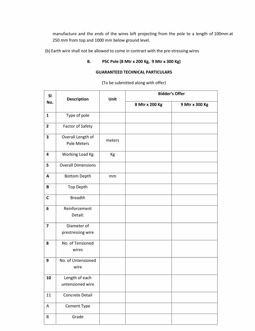
B. PSC Pole (8 Mtr x 200 Kg, 9 Mtr x 300 Kg)
GUARANTEED TECHNICAL PARTICULARS
(To be submitted along with offer)
Sl
No. Description Unit
Bidder’s Offer
8 Mtr x 200 Kg 9 Mtr x 300 Kg
1 Type of pole
2 Factor of Safety
3 Overall Length of
Pole Meters meters
4 Working Load Kg Kg
5 Overall Dimensions
A Bottom Depth mm
B Top Depth
C Breadth
6 Reinforcement
Detail:
7 Diameter of
prestressing wire
8 No. of Tensioned
wires
9 No. of Untensioned
wire
10 Length of each
untensioned wire
11 Concrete Detail
A Cement Type
B Grade
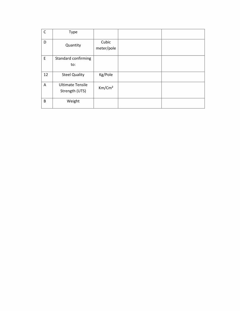
C Type
D Quantity
Cubic
meter/pole
E Standard confirming
to:
12 Steel Quality Kg/Pole
A Ultimate Tensile
Strength (UTS) Km/Cm²
B Weight
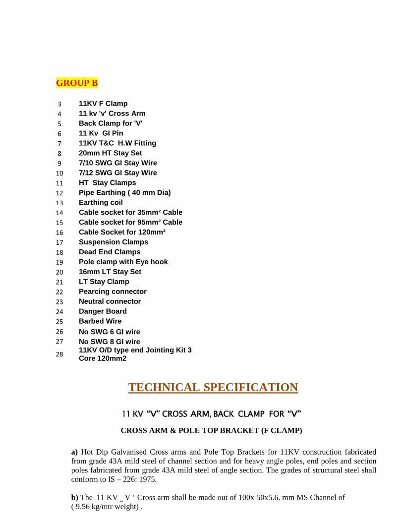
GROUP B
3 11KV F Clamp
4 11 kv 'v' Cross Arm
5 Back Clamp for 'V'
6 11 Kv GI Pin
7 11KV T&C H.W Fitting
8 20mm HT Stay Set
9 7/10 SWG GI Stay Wire
10 7/12 SWG GI Stay Wire
11 HT Stay Clamps
12 Pipe Earthing ( 40 mm Dia)
13 Earthing coil
14 Cable socket for 35mm² Cable
15 Cable socket for 95mm² Cable
16 Cable Socket for 120mm²
17 Suspension Clamps
18 Dead End Clamps
19 Pole clamp with Eye hook
20 16mm LT Stay Set
21 LT Stay Clamp
22 Pearcing connector
23 Neutral connector
24 Danger Board
25 Barbed Wire
26 No SWG 6 GI wire
27 No SWG 8 GI wire
28 11KV O/D type end Jointing Kit 3 Core 120mm2
TECHNICAL SPECIFICATION
11 KV “V” CROSS ARM, BACK CLAMP FOR “V”
CROSS ARM & POLE TOP BRACKET (F CLAMP)
a) Hot Dip Galvanised Cross arms and Pole Top Brackets for 11KV construction fabricated
from grade 43A mild steel of channel section and for heavy angle poles, end poles and section
poles fabricated from grade 43A mild steel of angle section. The grades of structural steel shall
conform to IS – 226: 1975.
b) The 11 KV ‗ V „ Cross arm shall be made out of 100x 50x5.6. mm MS Channel of
( 9.56 kg/mtr weight) .
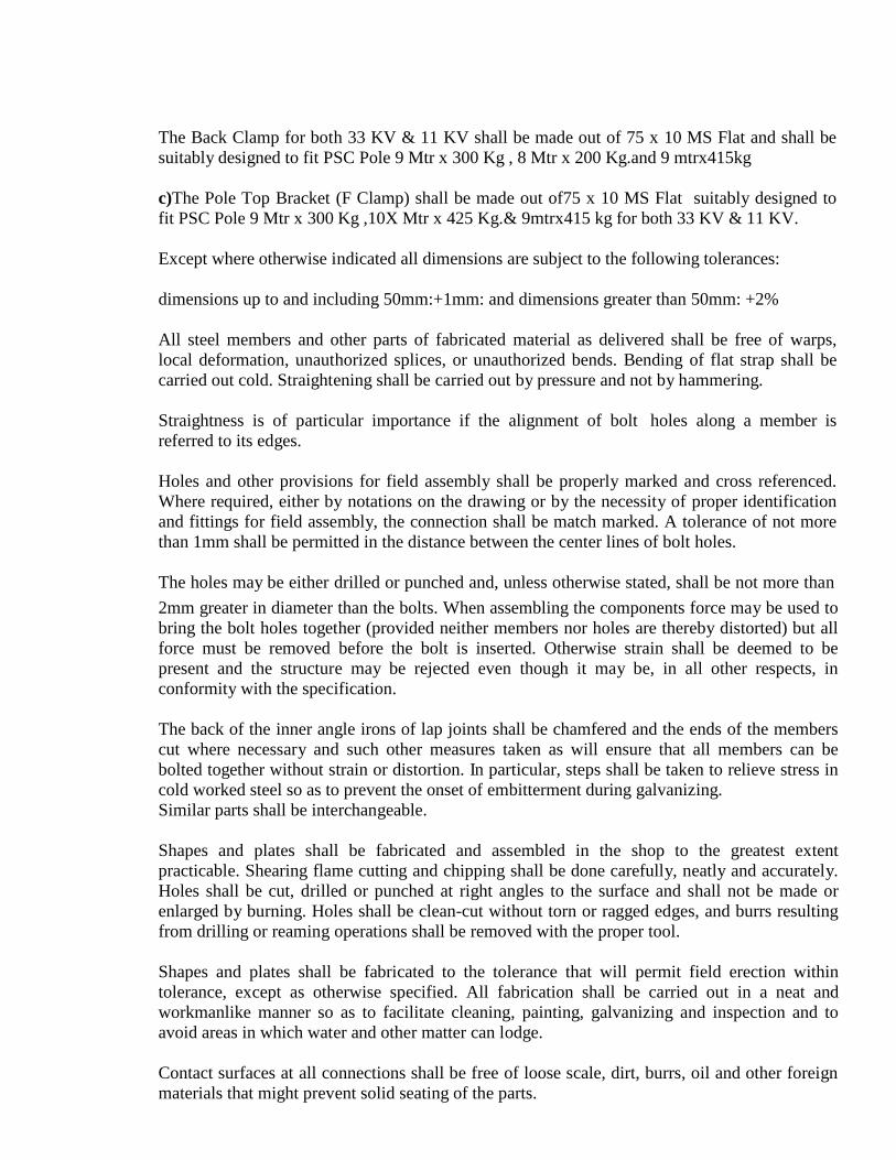
The Back Clamp for both 33 KV & 11 KV shall be made out of 75 x 10 MS Flat and shall be
suitably designed to fit PSC Pole 9 Mtr x 300 Kg , 8 Mtr x 200 Kg.and 9 mtrx415kg
c)The Pole Top Bracket (F Clamp) shall be made out of75 x 10 MS Flat suitably designed to
fit PSC Pole 9 Mtr x 300 Kg ,10X Mtr x 425 Kg.& 9mtrx415 kg for both 33 KV & 11 KV.
Except where otherwise indicated all dimensions are subject to the following tolerances:
dimensions up to and including 50mm:+1mm: and dimensions greater than 50mm: +2%
All steel members and other parts of fabricated material as delivered shall be free of warps,
local deformation, unauthorized splices, or unauthorized bends. Bending of flat strap shall be
carried out cold. Straightening shall be carried out by pressure and not by hammering.
Straightness is of particular importance if the alignment of bolt holes along a member is
referred to its edges.
Holes and other provisions for field assembly shall be properly marked and cross referenced.
Where required, either by notations on the drawing or by the necessity of proper identification
and fittings for field assembly, the connection shall be match marked. A tolerance of not more
than 1mm shall be permitted in the distance between the center lines of bolt holes.
The holes may be either drilled or punched and, unless otherwise stated, shall be not more than
2mm greater in diameter than the bolts. When assembling the components force may be used to
bring the bolt holes together (provided neither members nor holes are thereby distorted) but all
force must be removed before the bolt is inserted. Otherwise strain shall be deemed to be
present and the structure may be rejected even though it may be, in all other respects, in
conformity with the specification.
The back of the inner angle irons of lap joints shall be chamfered and the ends of the members
cut where necessary and such other measures taken as will ensure that all members can be
bolted together without strain or distortion. In particular, steps shall be taken to relieve stress in
cold worked steel so as to prevent the onset of embitterment during galvanizing.
Similar parts shall be interchangeable.
Shapes and plates shall be fabricated and assembled in the shop to the greatest extent
practicable. Shearing flame cutting and chipping shall be done carefully, neatly and accurately.
Holes shall be cut, drilled or punched at right angles to the surface and shall not be made or
enlarged by burning. Holes shall be clean-cut without torn or ragged edges, and burrs resulting
from drilling or reaming operations shall be removed with the proper tool.
Shapes and plates shall be fabricated to the tolerance that will permit field erection within
tolerance, except as otherwise specified. All fabrication shall be carried out in a neat and
workmanlike manner so as to facilitate cleaning, painting, galvanizing and inspection and to
avoid areas in which water and other matter can lodge.
Contact surfaces at all connections shall be free of loose scale, dirt, burrs, oil and other foreign
materials that might prevent solid seating of the parts.
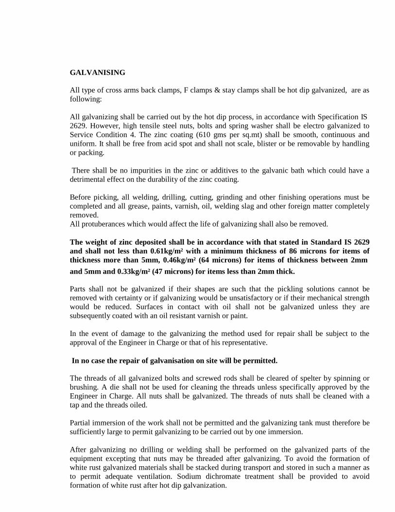
GALVANISING
All type of cross arms back clamps, F clamps & stay clamps shall be hot dip galvanized, are as
following:
All galvanizing shall be carried out by the hot dip process, in accordance with Specification IS
2629. However, high tensile steel nuts, bolts and spring washer shall be electro galvanized to
Service Condition 4. The zinc coating (610 gms per sq.mt) shall be smooth, continuous and
uniform. It shall be free from acid spot and shall not scale, blister or be removable by handling
or packing.
There shall be no impurities in the zinc or additives to the galvanic bath which could have a
detrimental effect on the durability of the zinc coating.
Before picking, all welding, drilling, cutting, grinding and other finishing operations must be
completed and all grease, paints, varnish, oil, welding slag and other foreign matter completely
removed.
All protuberances which would affect the life of galvanizing shall also be removed.
The weight of zinc deposited shall be in accordance with that stated in Standard IS 2629
and shall not less than 0.61kg/m² with a minimum thickness of 86 microns for items of
thickness more than 5mm, 0.46kg/m² (64 microns) for items of thickness between 2mm
and 5mm and 0.33kg/m² (47 microns) for items less than 2mm thick.
Parts shall not be galvanized if their shapes are such that the pickling solutions cannot be
removed with certainty or if galvanizing would be unsatisfactory or if their mechanical strength
would be reduced. Surfaces in contact with oil shall not be galvanized unless they are
subsequently coated with an oil resistant varnish or paint.
In the event of damage to the galvanizing the method used for repair shall be subject to the
approval of the Engineer in Charge or that of his representative.
In no case the repair of galvanisation on site will be permitted.
The threads of all galvanized bolts and screwed rods shall be cleared of spelter by spinning or
brushing. A die shall not be used for cleaning the threads unless specifically approved by the
Engineer in Charge. All nuts shall be galvanized. The threads of nuts shall be cleaned with a
tap and the threads oiled.
Partial immersion of the work shall not be permitted and the galvanizing tank must therefore be
sufficiently large to permit galvanizing to be carried out by one immersion.
After galvanizing no drilling or welding shall be performed on the galvanized parts of the
equipment excepting that nuts may be threaded after galvanizing. To avoid the formation of
white rust galvanized materials shall be stacked during transport and stored in such a manner as
to permit adequate ventilation. Sodium dichromate treatment shall be provided to avoid
formation of white rust after hot dip galvanization.
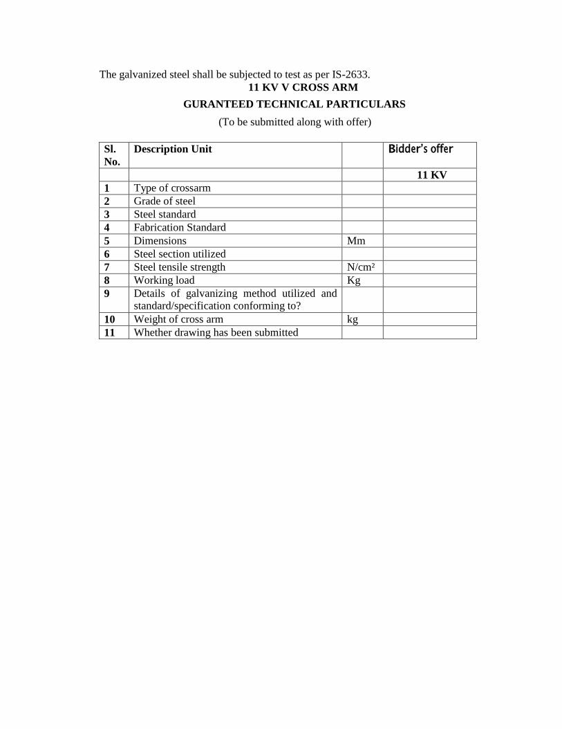
The galvanized steel shall be subjected to test as per IS-2633.
11 KV V CROSS ARM
GURANTEED TECHNICAL PARTICULARS
(To be submitted along with offer)
Sl.
No.
Description Unit Bidder’s offer
11 KV
1 Type of crossarm
2 Grade of steel
3 Steel standard
4 Fabrication Standard
5 Dimensions Mm
6 Steel section utilized
7 Steel tensile strength N/cm²
8 Working load Kg
9 Details of galvanizing method utilized and standard/specification conforming to?
10 Weight of cross arm kg
11 Whether drawing has been submitted
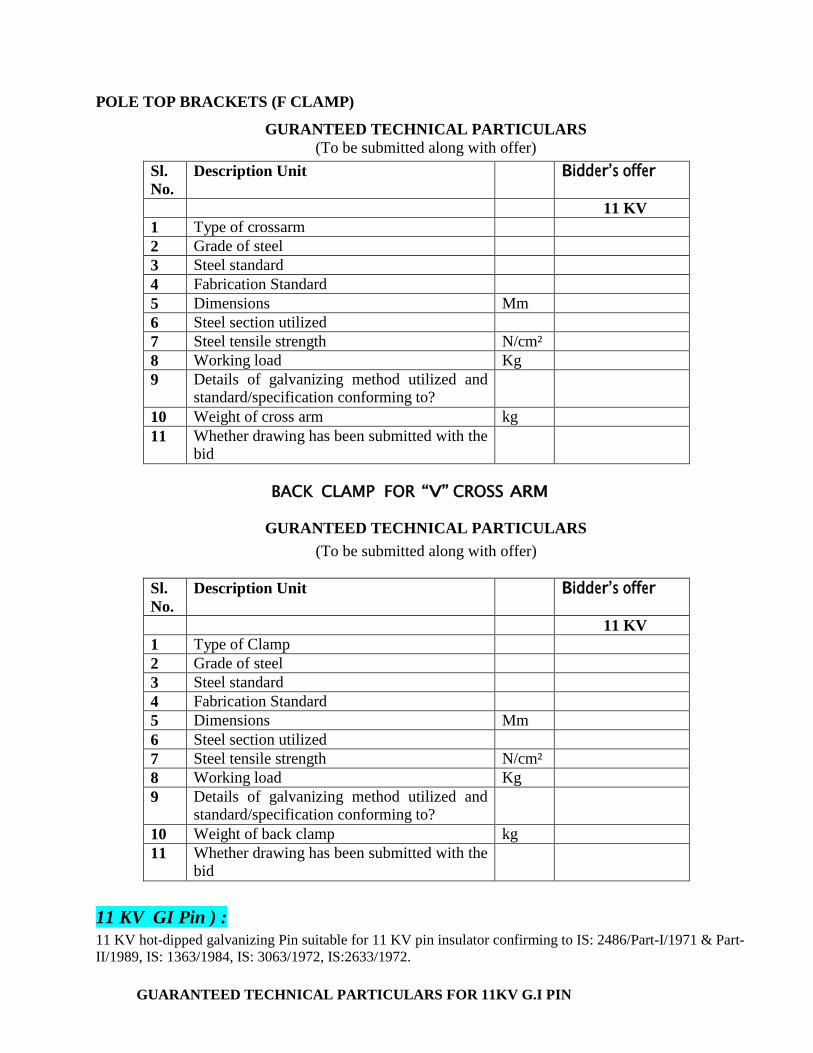
POLE TOP BRACKETS (F CLAMP)
GURANTEED TECHNICAL PARTICULARS
(To be submitted along with offer)
Sl.
No.
Description Unit Bidder’s offer
11 KV
1 Type of crossarm
2 Grade of steel
3 Steel standard
4 Fabrication Standard
5 Dimensions Mm
6 Steel section utilized
7 Steel tensile strength N/cm²
8 Working load Kg
9 Details of galvanizing method utilized and standard/specification conforming to?
10 Weight of cross arm kg
11 Whether drawing has been submitted with the bid
BACK CLAMP FOR “V” CROSS ARM
GURANTEED TECHNICAL PARTICULARS
(To be submitted along with offer)
Sl.
No.
Description Unit Bidder’s offer
11 KV
1 Type of Clamp
2 Grade of steel
3 Steel standard
4 Fabrication Standard
5 Dimensions Mm
6 Steel section utilized
7 Steel tensile strength N/cm²
8 Working load Kg
9 Details of galvanizing method utilized and standard/specification conforming to?
10 Weight of back clamp kg
11 Whether drawing has been submitted with the bid
11 KV GI Pin ) :
11 KV hot-dipped galvanizing Pin suitable for 11 KV pin insulator confirming to IS: 2486/Part-I/1971 & Part-
II/1989, IS: 1363/1984, IS: 3063/1972, IS:2633/1972.
GUARANTEED TECHNICAL PARTICULARS FOR 11KV G.I PIN
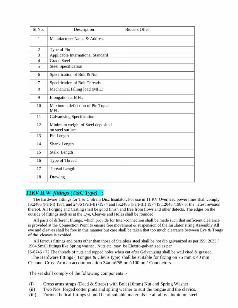
Sl.No. Description Bidders Offer
1 Manufacturer Name & Address
2 Type of Pin
3 Applicable International Standard
4 Grade Steel
5 Steel Specification
6 Specification of Bolt & Nut
7 Specification of Bolt Threads
8 Mechanical falling load (MFL)
9 Elongation at MFL
10 Maximum deflection of Pin Top at
MFL
11 Galvanising Specification
12 Minimum weight of Steel deposited
on steel surface
13 Pin Length
14 Shank Length
15 Stalk Length
16 Type of Thread
17 Thread Length
18 Drawing
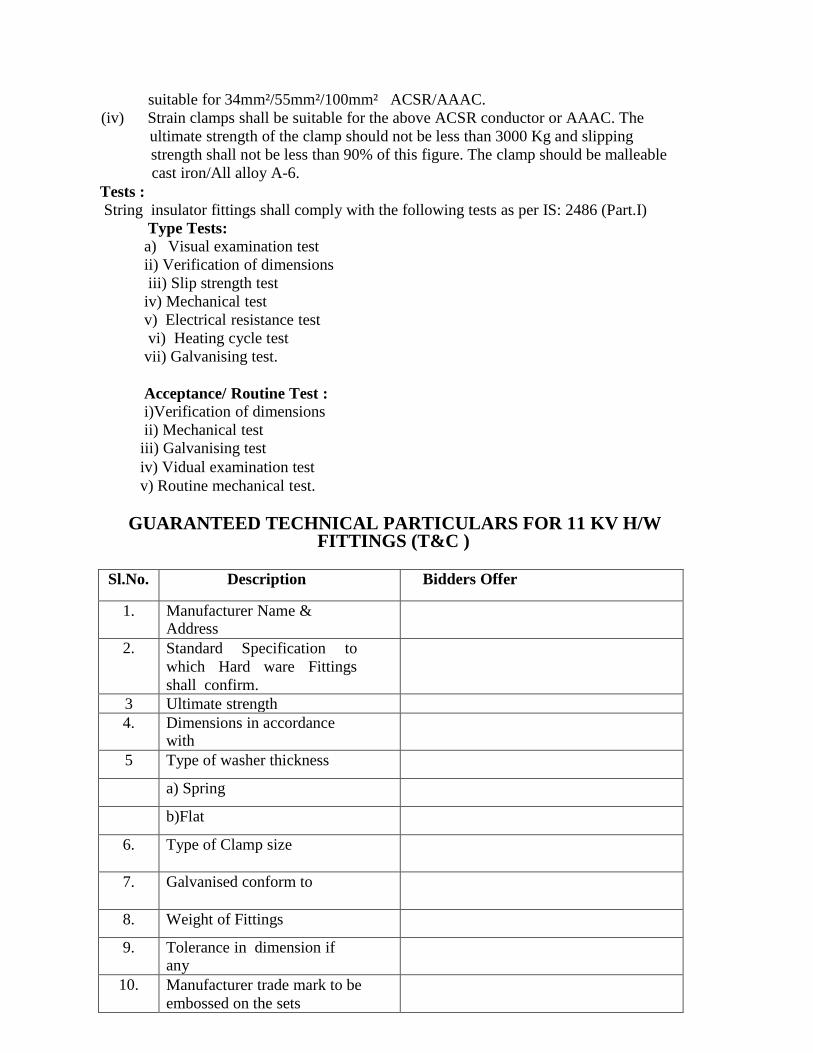
11KV H.W fittings (T&C Type) :
The hardware fittings for T & C Strain Disc Insulator. For use in 11 KV Overhead power lines shall comply
IS:2486 (Part-I) 1971 and 2486 (Part-II) /1974 and IS:2486 (Part-III) 1974 IS:12048 /1987 or the latest revision
thereof. All Forging and Casting shall be good finish and free from flows and other defects. The edges on the
outside of fittings such as at the Eye, Cleaves and Holes shall be rounded.
All parts of different fittings, which provide for Inter-connection shall be made such that sufficient clearance
is provided at the Connection Point to ensure free movement & suspension of the Insulator string Assembly.All
eye and cleaves shall be free in this manner but care shall be taken that too much clearance between Eye & Tongs
of the cleaves is avoided.
All ferrous fittings and parts other than those of Stainless steel shall be hot dip galvanized as per ISS: 2633 /
1964.Small fittings like Spring washer , Nuts etc. may be Electro-galvanized as per
IS-6745 / 72.The threads of nuts and topped holes when cut after Galvanizing shall be well cited & grassed.
The Hardware fittings ( Tongue & Clevis type) shall be suitable for fixing on 75 mm x 40 mm
Channel Cross Arm an accommodation 34mm²/55mm²/100mm² Conductors.
The set shall comply of the following components :-
(i) Cross arms straps (Dead & Straps) with Bolt (16mm) Nut and Spring Washer.
(ii) Two Nos. forged cotter pints and spring washer to suit the tongue and the clevics.
(iii) Formed helical fittings should be of suitable materials i.e all alloy aluminum steel
suitable for 34mm²/55mm²/100mm² ACSR/AAAC.
(iv) Strain clamps shall be suitable for the above ACSR conductor or AAAC. The
ultimate strength of the clamp should not be less than 3000 Kg and slipping
strength shall not be less than 90% of this figure. The clamp should be malleable
cast iron/All alloy A-6.
Tests :
String insulator fittings shall comply with the following tests as per IS: 2486 (Part.I)
Type Tests:
a) Visual examination test
ii) Verification of dimensions
iii) Slip strength test
iv) Mechanical test
v) Electrical resistance test
vi) Heating cycle test
vii) Galvanising test.
Acceptance/ Routine Test :
i)Verification of dimensions
ii) Mechanical test
iii) Galvanising test
iv) Vidual examination test
v) Routine mechanical test.
GUARANTEED TECHNICAL PARTICULARS FOR 11 KV H/W FITTINGS (T&C )
Sl.No. Description Bidders Offer
1. Manufacturer Name & Address
2. Standard Specification to
which Hard ware Fittings
shall confirm.
3 Ultimate strength
4. Dimensions in accordance with
5 Type of washer thickness
a) Spring
b)Flat
6. Type of Clamp size
7. Galvanised conform to
8. Weight of Fittings
9. Tolerance in dimension if any
10. Manufacturer trade mark to be
embossed on the sets
11. Specific drawing to be enclosed.
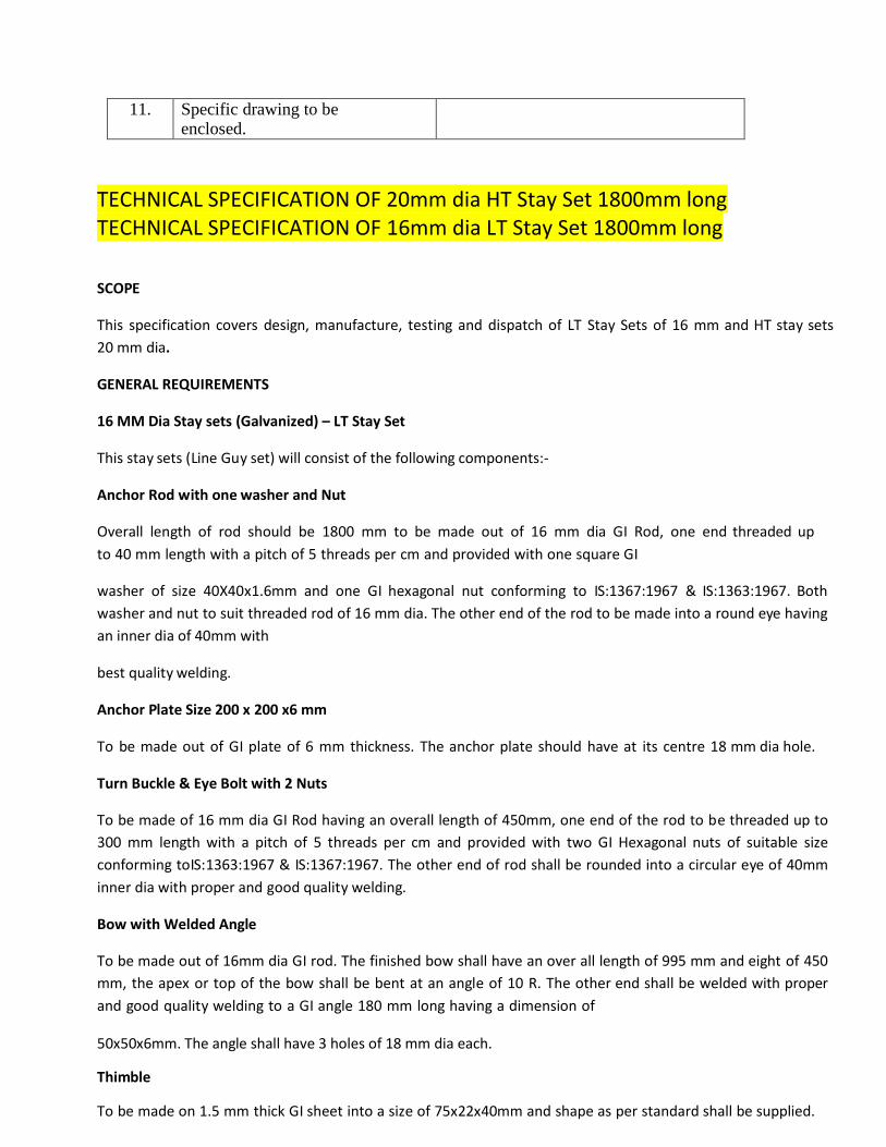
TECHNICAL SPECIFICATION OF 20mm dia HT Stay Set 1800mm long
TECHNICAL SPECIFICATION OF 16mm dia LT Stay Set 1800mm long
SCOPE
This specification covers design, manufacture, testing and dispatch of LT Stay Sets of 16 mm and HT stay sets
20 mm dia.
GENERAL REQUIREMENTS
16 MM Dia Stay sets (Galvanized) – LT Stay Set
This stay sets (Line Guy set) will consist of the following components:-
Anchor Rod with one washer and Nut
Overall length of rod should be 1800 mm to be made out of 16 mm dia GI Rod, one end threaded up
to 40 mm length with a pitch of 5 threads per cm and provided with one square GI
washer of size 40X40x1.6mm and one GI hexagonal nut conforming to IS:1367:1967 & IS:1363:1967. Both
washer and nut to suit threaded rod of 16 mm dia. The other end of the rod to be made into a round eye having
an inner dia of 40mm with
best quality welding.
Anchor Plate Size 200 x 200 x6 mm
To be made out of GI plate of 6 mm thickness. The anchor plate should have at its centre 18 mm dia hole.
Turn Buckle & Eye Bolt with 2 Nuts
To be made of 16 mm dia GI Rod having an overall length of 450mm, one end of the rod to be threaded up to
300 mm length with a pitch of 5 threads per cm and provided with two GI Hexagonal nuts of suitable size
conforming toIS:1363:1967 & IS:1367:1967. The other end of rod shall be rounded into a circular eye of 40mm
inner dia with proper and good quality welding.
Bow with Welded Angle
To be made out of 16mm dia GI rod. The finished bow shall have an over all length of 995 mm and eight of 450
mm, the apex or top of the bow shall be bent at an angle of 10 R. The other end shall be welded with proper
and good quality welding to a GI angle 180 mm long having a dimension of
50x50x6mm. The angle shall have 3 holes of 18 mm dia each.
Thimble
To be made on 1.5 mm thick GI sheet into a size of 75x22x40mm and shape as per standard shall be supplied.
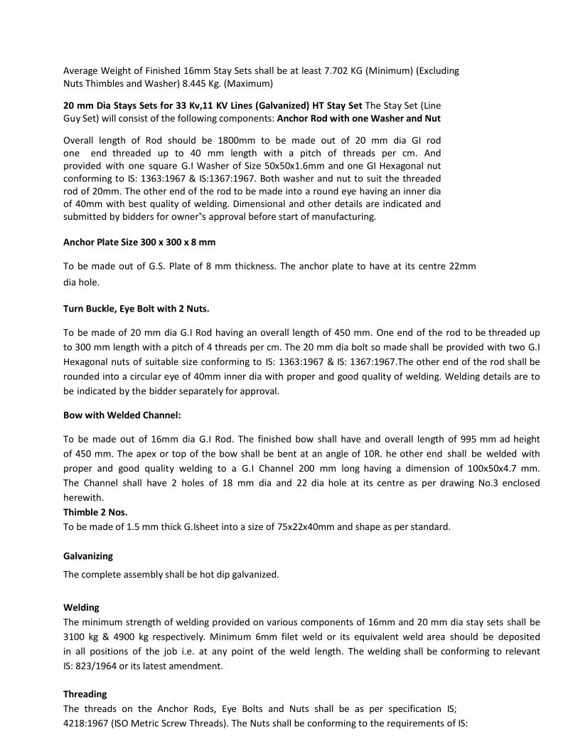
Average Weight of Finished 16mm Stay Sets shall be at least 7.702 KG (Minimum) (Excluding Nuts Thimbles and Washer) 8.445 Kg. (Maximum)
20 mm Dia Stays Sets for 33 Kv,11 KV Lines (Galvanized) HT Stay Set The Stay Set (Line Guy Set) will consist of the following components: Anchor Rod with one Washer and Nut
Overall length of Rod should be 1800mm to be made out of 20 mm dia GI rod one end threaded up to 40 mm length with a pitch of threads per cm. And provided with one square G.I Washer of Size 50x50x1.6mm and one GI Hexagonal nut conforming to IS: 1363:1967 & IS:1367:1967. Both washer and nut to suit the threaded rod of 20mm. The other end of the rod to be made into a round eye having an inner dia of 40mm with best quality of welding. Dimensional and other details are indicated and submitted by bidders for owner‟s approval before start of manufacturing. Anchor Plate Size 300 x 300 x 8 mm
To be made out of G.S. Plate of 8 mm thickness. The anchor plate to have at its centre 22mm
dia hole.
Turn Buckle, Eye Bolt with 2 Nuts.
To be made of 20 mm dia G.I Rod having an overall length of 450 mm. One end of the rod to be threaded up
to 300 mm length with a pitch of 4 threads per cm. The 20 mm dia bolt so made shall be provided with two G.I
Hexagonal nuts of suitable size conforming to IS: 1363:1967 & IS: 1367:1967.The other end of the rod shall be
rounded into a circular eye of 40mm inner dia with proper and good quality of welding. Welding details are to
be indicated by the bidder separately for approval.
Bow with Welded Channel:
To be made out of 16mm dia G.I Rod. The finished bow shall have and overall length of 995 mm ad height
of 450 mm. The apex or top of the bow shall be bent at an angle of 10R. he other end shall be welded with
proper and good quality welding to a G.I Channel 200 mm long having a dimension of 100x50x4.7 mm.
The Channel shall have 2 holes of 18 mm dia and 22 dia hole at its centre as per drawing No.3 enclosed
herewith.
Thimble 2 Nos.
To be made of 1.5 mm thick G.Isheet into a size of 75x22x40mm and shape as per standard.
Galvanizing
The complete assembly shall be hot dip galvanized.
Welding
The minimum strength of welding provided on various components of 16mm and 20 mm dia stay sets shall be
3100 kg & 4900 kg respectively. Minimum 6mm filet weld or its equivalent weld area should be deposited
in all positions of the job i.e. at any point of the weld length. The welding shall be conforming to relevant
IS: 823/1964 or its latest amendment.
Threading
The threads on the Anchor Rods, Eye Bolts and Nuts shall be as per specification IS;
4218:1967 (ISO Metric Screw Threads). The Nuts shall be conforming to the requirements of IS:
1367:1967 and have dimension as per IS 1363:1967. The mechanical property requirement of fasteners shall
confirm to the properly clause 4.6 each for anchor rods and Eye bolt and property clause 4 for nuts as per IS:
1367:1967.
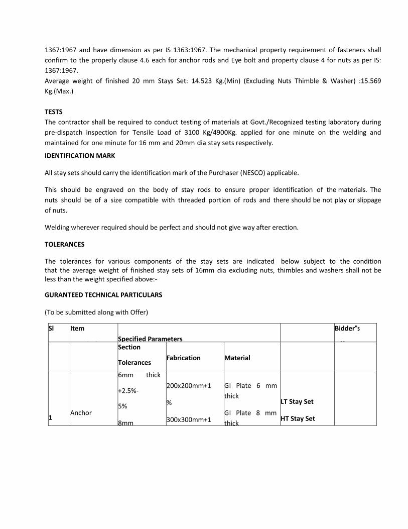
Average weight of finished 20 mm Stays Set: 14.523 Kg.(Min) (Excluding Nuts Thimble & Washer) :15.569
Kg.(Max.)
TESTS
The contractor shall be required to conduct testing of materials at Govt./Recognized testing laboratory during
pre-dispatch inspection for Tensile Load of 3100 Kg/4900Kg. applied for one minute on the welding and
maintained for one minute for 16 mm and 20mm dia stay sets respectively.
IDENTIFICATION MARK
All stay sets should carry the identification mark of the Purchaser (NESCO) applicable.
This should be engraved on the body of stay rods to ensure proper identification of the materials. The
nuts should be of a size compatible with threaded portion of rods and there should be not play or slippage
of nuts.
Welding wherever required should be perfect and should not give way after erection.
TOLERANCES
The tolerances for various components of the stay sets are indicated below subject to the condition that the average weight of finished stay sets of 16mm dia excluding nuts, thimbles and washers shall not be less than the weight specified above:-
GURANTEED TECHNICAL PARTICULARS
(To be submitted along with Offer)
Sl
No.
Item
Description
Specified Parameters
Bidder‟s
Offer Section
Tolerances
Fabrication
Tolerances
Material
1
Anchor
Plate
6mm thick
+2.5%-
5%
8mm
thick+2.5%-
5%
200x200mm+1
%
300x300mm+1
%
GI Plate 6 mm
thick
GI Plate 8 mm
thick
LT Stay Set
HT Stay Set
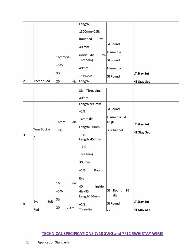
2
Anchor Rod
16mmdia
+5%-
3%
20mm dia
+3%-
2%
Length
1800mm+0.5%
Rounded Eye
40 mm
inside dia + 3%
Threading
40mm
+11%-5%
Length
1800mm
+0.5% Round
Eye
40mm inside
dia +
GI Round
16mm dia
GI Round
16mm dia
GI Round
20mm dai
GI Round
20mm dia
LT Stay Set
HT Stay Set
3%. Threading
40mm
+11%-5%
3
Turn Buckle
Bow
16mm dia
+5%-
3%
Length 995mm
+1%
16mm dia
Length180mm
+1%
50x50x6mm
Channel length
200mm + 1%
GI Round
16mm dia. GI
Angle
G I Channel
100x50x4.7m m
LT Stay Set
HT Stay Set
4
Eye Bolt
Rod
16mm dia
+5%-
3%
20mm dia +
3% -
2%
Length 450mm
+ 1%
Threading
300mm
+1% Round
Eye
40mm inside
dia+3%
Length450mm
+1%
Threading
300mm
+1% Round
Eye 40
mm inside dia
+3%
GI Round 16
mm dia
GI Round
20mm dia.
LT Stay Set
HT Stay Set
TECHNICAL SPECIFICATIONS 7/10 SWG and 7/12 SWG STAY WIRE)
1. Application Standards
Except when they conflict with the specific requirements of this specification, the
G.I Stay Stranded Wires shall comply with the specific requirements of IS: 2141-
1979. IS: 4826-1979 & IS: 6594-1974 or the latest versions thereof.
2. Application and Sizes
a) The G.I. stranded wires covered in this Specification are intended for use on the overhead power line poles, distribution transformer structures etc.
b) The G.I stranded wires shall be of 7/8 SWG ( 7/4.0 mm for 33 KV lines), 7/12 SWG( 7/3.15 mm for 11KV lines) and 7/12 SWG (7/2.5 mm for LT lines) standard sizes.
3. Materials
The wires shall be drawn from steel made by the open hearth basic oxygen or electric furnace process and of such quality that when drawn to the size of wire specified and coated with zinc, the finished strand and the individual wires shall be of uniform quality and have the properties and characteristics as specified in this specification. The wires shall not contain sulphur and phosphorus exceeding 0.060% each.
3.1 Tensile Grade
The wires shall be of tensile grade 4, having minimum tensile strength of 700
N/mm² conforming to 1S:2141.
3.2 General Requirements
a) The outer wire of strands shall have a right-hand lay.
b) The lay length of wire strands shall be 12 to 19 times the strand diameter.
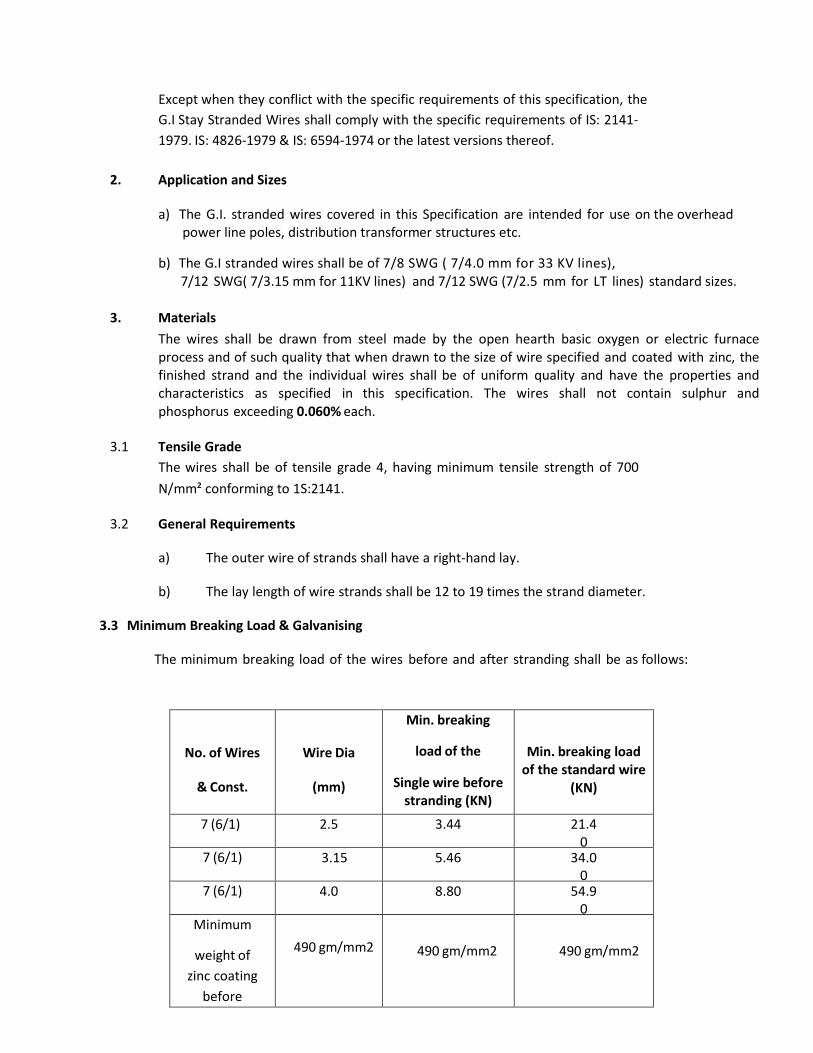
3.3 Minimum Breaking Load & Galvanising
The minimum breaking load of the wires before and after stranding shall be as follows:
No. of Wires
& Const.
Wire Dia
(mm)
Min. breaking
load of the
Single wire before stranding (KN)
Min. breaking load of the standard wire
(KN)
7 (6/1) 2.5 3.44 21.40
7 (6/1) 3.15 5.46 34.00
7 (6/1) 4.0 8.80 54.90
Minimum
weight of
zinc coating
before
stranding
490 gm/mm2
490 gm/mm2
490 gm/mm2
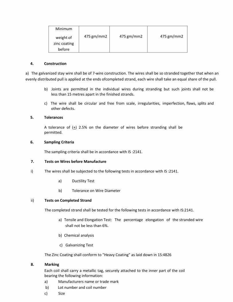
Minimum
weight of
zinc coating
before
stranding
475 gm/mm2
475 gm/mm2
475 gm/mm2
4. Construction
a) The galvanized stay wire shall be of 7-wire construction. The wires shall be so stranded together that when an
evenly distributed pull is applied at the ends ofcompleted strand, each wire shall take an equal share of the pull.
b) Joints are permitted in the individual wires during stranding but such joints shall not be less than 15 metres apart in the finished strands.
c) The wire shall be circular and free from scale, irregularities, imperfection, flaws, splits and other defects.
5. Tolerances
A tolerance of (+) 2.5% on the diameter of wires before stranding shall be permitted.
6. Sampling Criteria
The sampling criteria shall be in accordance with IS :2141.
7. Tests on Wires before Manufacture
i) The wires shall be subjected to the following tests in accordance with IS :2141.
a) Ductility Test
b) Tolerance on Wire Diameter
ii) Tests on Completed Strand
The completed strand shall be tested for the following tests in accordance with IS:2141.
a) Tensile and Elongation Test: The percentage elongation of the stranded wire
shall not be less than 6%.
b) Chemical analysis
c) Galvanizing Test
The Zinc Coating shall conform to "Heavy Coating" as laid down in 1S:4826
8. Marking
Each coil shall carry a metallic tag, securely attached to the inner part of the coil bearing the following information:
a) Manufacturers name or trade mark
b) Lot number and coil number
c) Size
d) Construction
e) Tensile Designation
f) Lay
g) Coating
h) Length
i) Mass
j) ISI certification mark, if any
9. Packing
The wires shall be supplied in 75-100 Kg. coils. The packing should be done in
accordance with the provisions of IS:6594.
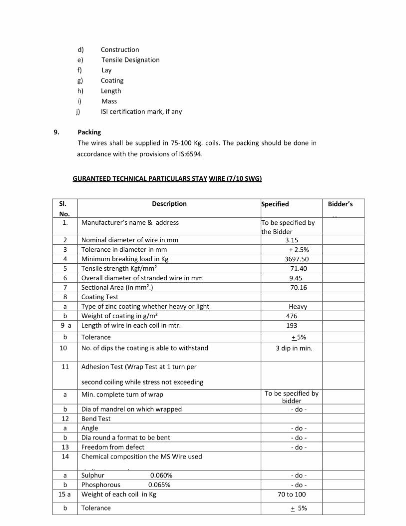
GURANTEED TECHNICAL PARTICULARS STAY WIRE (7/10 SWG)
Sl.
No.
Description Specified Bidder’s
offer 1. Manufacturer’s name & address To be specified by the Bidder
2 Nominal diameter of wire in mm 3.15
3 Tolerance in diameter in mm + 2.5%
4 Minimum breaking load in Kg 3697.50
5 Tensile strength Kgf/mm² 71.40
6 Overall diameter of stranded wire in mm 9.45
7 Sectional Area (in mm².) 70.16
8 Coating Test
a Type of zinc coating whether heavy or light Heavy
b Weight of coating in g/m² 476
9 a Length of wire in each coil in mtr. 193
b Tolerance + 5%
10 No. of dips the coating is able to withstand
as 18 ± 20ºC
3 dip in min.
11 Adhesion Test (Wrap Test at 1 turn per
second coiling while stress not exceeding
% nominal tensile strength)
a Min. complete turn of wrap To be specified by bidder
b Dia of mandrel on which wrapped - do -
12 Bend Test
a Angle - do -
b Dia round a format to be bent - do -
13 Freedom from defect - do -
14 Chemical composition the MS Wire used
shall not exceed
a Sulphur 0.060% - do -
b Phosphorous 0.065% - do -
15 a Weight of each coil in Kg 70 to 100
b Tolerance + 5%
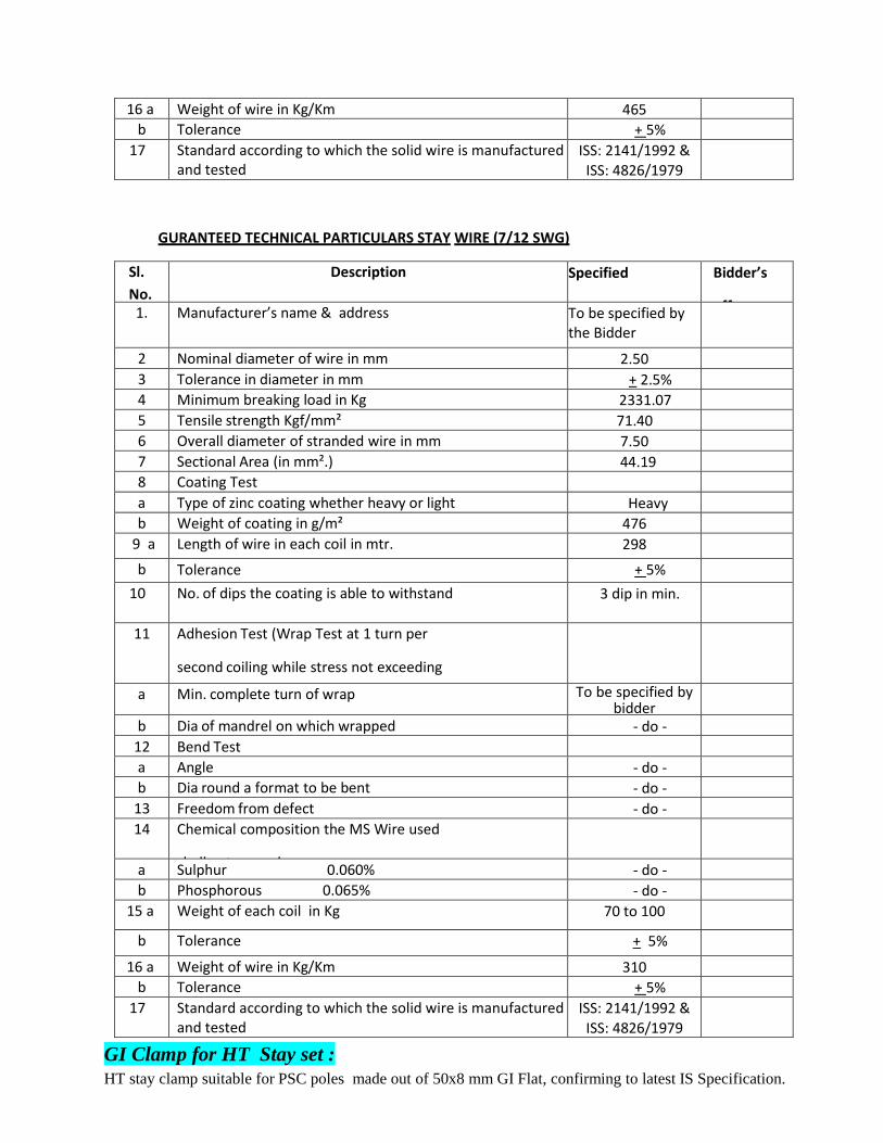
16 a Weight of wire in Kg/Km 465
b Tolerance + 5%
17 Standard according to which the solid wire is manufactured and tested
ISS: 2141/1992 & ISS: 4826/1979
GURANTEED TECHNICAL PARTICULARS STAY WIRE (7/12 SWG)
Sl.
No.
Description Specified Bidder’s
offer 1. Manufacturer’s name & address To be specified by the Bidder
2 Nominal diameter of wire in mm 2.50
3 Tolerance in diameter in mm + 2.5%
4 Minimum breaking load in Kg 2331.07
5 Tensile strength Kgf/mm² 71.40
6 Overall diameter of stranded wire in mm 7.50
7 Sectional Area (in mm².) 44.19
8 Coating Test
a Type of zinc coating whether heavy or light Heavy
b Weight of coating in g/m² 476
9 a Length of wire in each coil in mtr. 298
b Tolerance + 5%
10 No. of dips the coating is able to withstand
as 18 ± 20ºC
3 dip in min.
11 Adhesion Test (Wrap Test at 1 turn per
second coiling while stress not exceeding
% nominal tensile strength)
a Min. complete turn of wrap To be specified by bidder
b Dia of mandrel on which wrapped - do -
12 Bend Test
a Angle - do -
b Dia round a format to be bent - do -
13 Freedom from defect - do -
14 Chemical composition the MS Wire used
shall not exceed
a Sulphur 0.060% - do -
b Phosphorous 0.065% - do -
15 a Weight of each coil in Kg 70 to 100
b Tolerance + 5%
16 a Weight of wire in Kg/Km 310
b Tolerance + 5%
17 Standard according to which the solid wire is manufactured and tested
ISS: 2141/1992 & ISS: 4826/1979
GI Clamp for HT Stay set :
HT stay clamp suitable for PSC poles made out of 50x8 mm GI Flat, confirming to latest IS Specification.
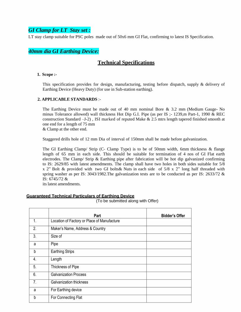
GI Clamp for LT Stay set :
LT stay clamp suitable for PSC poles made out of 50x6 mm GI Flat, confirming to latest IS Specification.
40mm dia GI Earthing Device:
Technical Specifications 1. Scope :-
This specification provides for design, manufacturing, testing before dispatch, supply & delivery of
Earthing Device (Heavy Duty) (for use in Sub-station earthing).
2. APPLICABLE STANDARDS :-
The Earthing Device must be made out of 40 mm nominal Bore & 3.2 mm (Medium Gauge- No
minus Tolerance allowed) wall thickness Hot Dip G.I. Pipe (as per IS ;- 1239,m Part-1, 1990 & REC
construction Standard –J-2) , ISI marked of reputed Make & 2.5 mtrs length tapered finished smooth at
one end for a length of 75 mm
& Clamp at the other end.
Staggered drills hole of 12 mm Dia of interval of 150mm shall be made before galvanization.
The GI Earthing Clamp/ Strip (C- Clamp Type) is to be of 50mm width, 6mm thickness & flange
length of 65 mm in each side. This should be suitable for termination of 4 nos of GI Flat earth
electrodes. The Clamp/ Strip & Earthing pipe after fabrication will be hot dip galvanized confirming
to IS: 2629/85 with latest amendments. The clamp shall have two holes in both sides suitable for 5/8
x 2” Bolt & provided with two GI bolts& Nuts in each side of 5/8 x 2” long half threaded with
spring washer as per IS: 3043/1982.The galvanization tests are to be conducted as per IS: 2633/72 &
IS: 6745/72 &
its latest amendments.
Guaranteed Technical Particulars of Earthing Device
(To be submitted along with Offer)
Sl. No. Particulars
Bidder’s Offer
1. Location of Factory or Place of Manufacture
2. Maker’s Name, Address & Country
3. Size of
a Pipe
b Earthing Strips
4. Length
5. Thickness of Pipe
6. Galvanization Process
7. Galvanization thickness
a For Earthing device
b For Connecting Flat
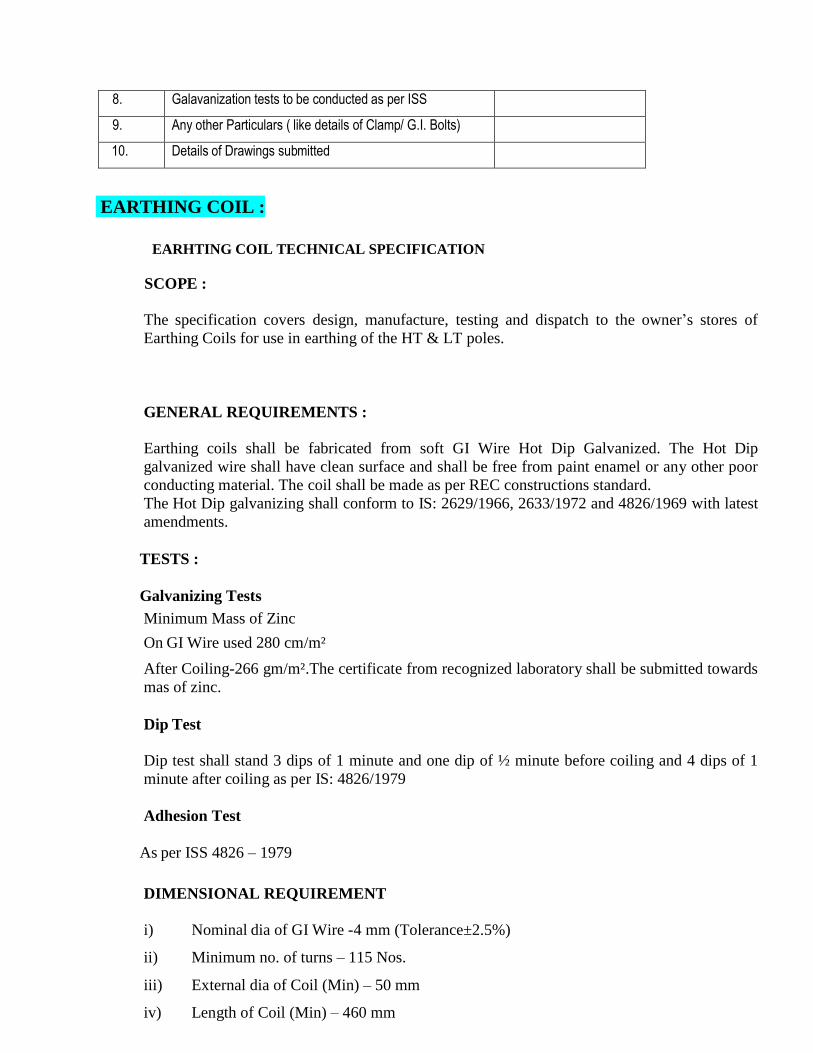
8. Galavanization tests to be conducted as per ISS
9. Any other Particulars ( like details of Clamp/ G.I. Bolts)
10. Details of Drawings submitted
EARTHING COIL :
EARHTING COIL TECHNICAL SPECIFICATION
SCOPE :
The specification covers design, manufacture, testing and dispatch to the owner‟s stores of
Earthing Coils for use in earthing of the HT & LT poles.
GENERAL REQUIREMENTS :
Earthing coils shall be fabricated from soft GI Wire Hot Dip Galvanized. The Hot Dip
galvanized wire shall have clean surface and shall be free from paint enamel or any other poor
conducting material. The coil shall be made as per REC constructions standard.
The Hot Dip galvanizing shall conform to IS: 2629/1966, 2633/1972 and 4826/1969 with latest
amendments.
TESTS :
Galvanizing Tests
Minimum Mass of Zinc
On GI Wire used 280 cm/m²
After Coiling-266 gm/m².The certificate from recognized laboratory shall be submitted towards
mas of zinc.
Dip Test
Dip test shall stand 3 dips of 1 minute and one dip of ½ minute before coiling and 4 dips of 1
minute after coiling as per IS: 4826/1979
Adhesion Test
As per ISS 4826 – 1979
DIMENSIONAL REQUIREMENT
i) Nominal dia of GI Wire -4 mm (Tolerance±2.5%)
ii) Minimum no. of turns – 115 Nos.
iii) External dia of Coil (Min) – 50 mm
iv) Length of Coil (Min) – 460 mm
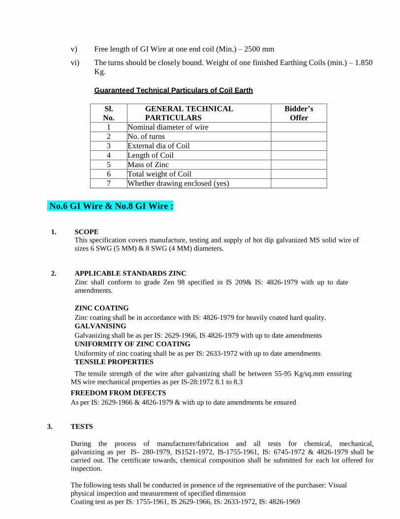
v) Free length of GI Wire at one end coil (Min.) – 2500 mm
vi) The turns should be closely bound. Weight of one finished Earthing Coils (min.) – 1.850
Kg.
Guaranteed Technical Particulars of Coil Earth
Sl.
No.
GENERAL TECHNICAL
PARTICULARS
Bidder’s
Offer
1 Nominal diameter of wire
2 No. of turns
3 External dia of Coil
4 Length of Coil
5 Mass of Zinc
6 Total weight of Coil
7 Whether drawing enclosed (yes)
No.6 GI Wire & No.8 GI Wire :
1. SCOPE This specification covers manufacture, testing and supply of hot dip galvanized MS solid wire of
sizes 6 SWG (5 MM) & 8 SWG (4 MM) diameters.
2. APPLICABLE STANDARDS ZINC
Zinc shall conform to grade Zen 98 specified in IS 209& IS: 4826-1979 with up to date
amendments.
ZINC COATING
Zinc coating shall be in accordance with IS: 4826-1979 for heavily coated hard quality.
GALVANISING
Galvanizing shall be as per IS: 2629-1966, IS 4826-1979 with up to date amendments
UNIFORMITY OF ZINC COATING
Uniformity of zinc coating shall be as per IS: 2633-1972 with up to date amendments
TENSILE PROPERTIES
The tensile strength of the wire after galvanizing shall be between 55-95 Kg/sq.mm ensuring
MS wire mechanical properties as per IS-28:1972 8.1 to 8.3
FREEDOM FROM DEFECTS
As per IS: 2629-1966 & 4826-1979 & with up to date amendments be ensured
3. TESTS
During the process of manufacturer/fabrication and all tests for chemical, mechanical,
galvanizing as per IS- 280-1979, IS1521-1972, IS-1755-1961, IS: 6745-1972 & 4826-1979 shall be
carried out. The certificate towards, chemical composition shall be submitted for each lot offered for
inspection.
The following tests shall be conducted in presence of the representative of the purchaser: Visual
physical inspection and measurement of specified dimension
Coating test as per IS: 1755-1961, IS 2629-1966, IS: 2633-1972, IS: 4826-1969
Adhesion test as per IS: 1755-1961, IS: 2629-1966, IS: 2633-1972, IS: 4826-1969,&
IS:6745-1972
Tensile strength and breaking load and elongation determined as per IS: 1521-1972 with up to date
amendments.
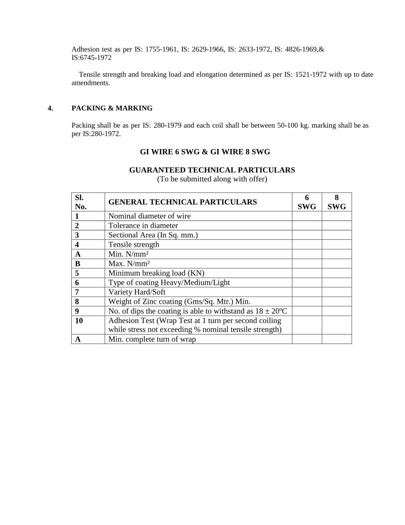
4. PACKING & MARKING
Packing shall be as per IS: 280-1979 and each coil shall be between 50-100 kg. marking shall be as
per IS:280-1972.
GI WIRE 6 SWG & GI WIRE 8 SWG
GUARANTEED TECHNICAL PARTICULARS (To be submitted along with offer)
Sl.
No.
GENERAL TECHNICAL PARTICULARS 6
SWG
8
SWG
1 Nominal diameter of wire
2 Tolerance in diameter
3 Sectional Area (In Sq. mm.)
4 Tensile strength
A Min. N/mm²
B Max. N/mm²
5 Minimum breaking load (KN)
6 Type of coating Heavy/Medium/Light
7 Variety Hard/Soft
8 Weight of Zinc coating (Gms/Sq. Mtr.) Min.
9 No. of dips the coating is able to withstand as 18 ± 20ºC
10 Adhesion Test (Wrap Test at 1 turn per second coiling while stress not exceeding % nominal tensile strength)
A Min. complete turn of wrap
B Dia of mandrel on which wrapped
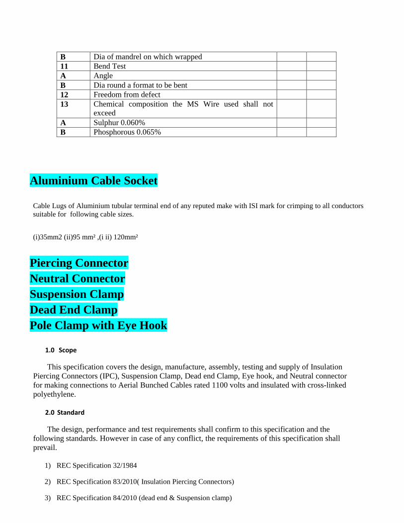
11 Bend Test
A Angle
B Dia round a format to be bent
12 Freedom from defect
13 Chemical composition the MS Wire used shall not exceed
A Sulphur 0.060%
B Phosphorous 0.065%
Aluminium Cable Socket
Cable Lugs of Aluminium tubular terminal end of any reputed make with ISI mark for crimping to all conductors
suitable for following cable sizes.
(i)35mm2 (ii)95 mm² ,(i ii) 120mm²
Piercing Connector
Neutral Connector
Suspension Clamp
Dead End Clamp
Pole Clamp with Eye Hook
1.0 Scope
This specification covers the design, manufacture, assembly, testing and supply of Insulation
Piercing Connectors (IPC), Suspension Clamp, Dead end Clamp, Eye hook, and Neutral connector
for making connections to Aerial Bunched Cables rated 1100 volts and insulated with cross-linked
polyethylene.
2.0 Standard
The design, performance and test requirements shall confirm to this specification and the
following standards. However in case of any conflict, the requirements of this specification shall
prevail.
1) REC Specification 32/1984
2) REC Specification 83/2010( Insulation Piercing Connectors)
3) REC Specification 84/2010 (dead end & Suspension clamp)
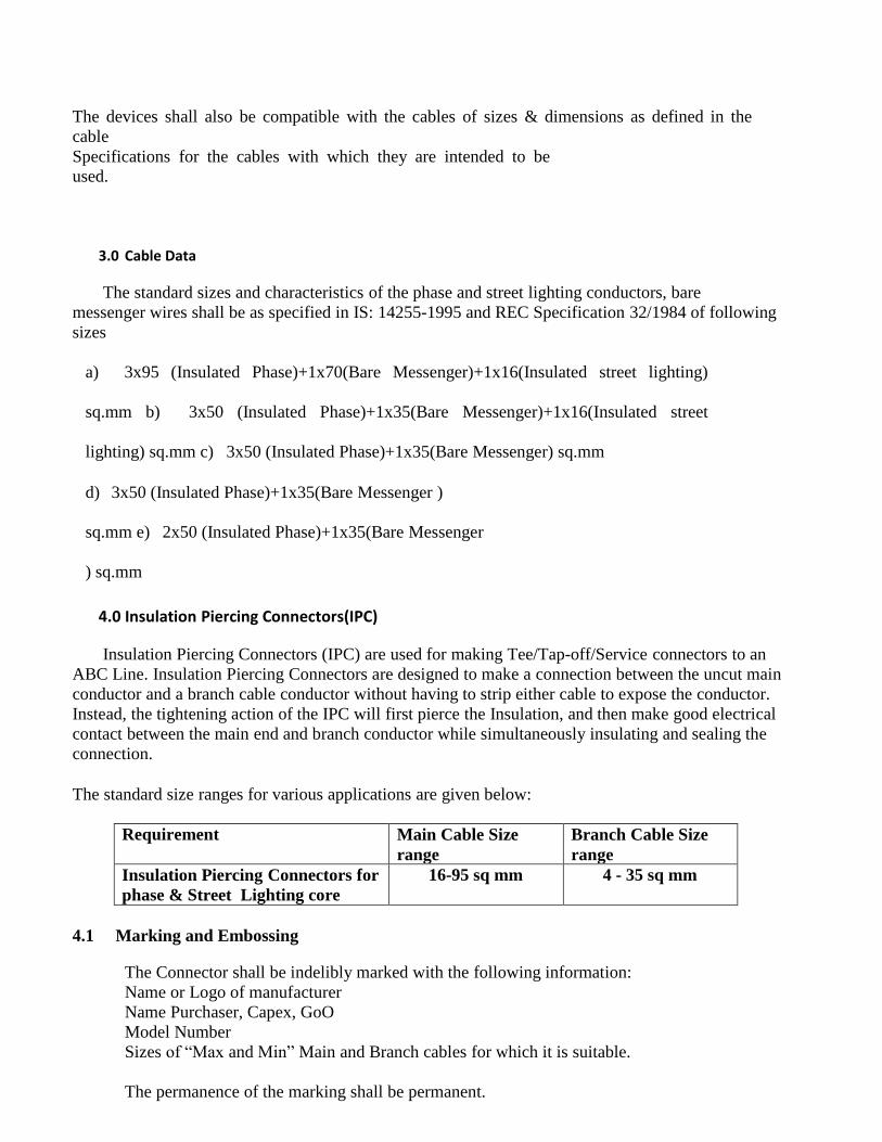
The devices shall also be compatible with the cables of sizes & dimensions as defined in the
cable
Specifications for the cables with which they are intended to be
used.
3.0 Cable Data
The standard sizes and characteristics of the phase and street lighting conductors, bare
messenger wires shall be as specified in IS: 14255-1995 and REC Specification 32/1984 of following
sizes
a) 3x95 (Insulated Phase)+1x70(Bare Messenger)+1x16(Insulated street lighting)
sq.mm b) 3x50 (Insulated Phase)+1x35(Bare Messenger)+1x16(Insulated street
lighting) sq.mm c) 3x50 (Insulated Phase)+1x35(Bare Messenger) sq.mm
d) 3x50 (Insulated Phase)+1x35(Bare Messenger )
sq.mm e) 2x50 (Insulated Phase)+1x35(Bare Messenger
) sq.mm
4.0 Insulation Piercing Connectors(IPC)
Insulation Piercing Connectors (IPC) are used for making Tee/Tap-off/Service connectors to an
ABC Line. Insulation Piercing Connectors are designed to make a connection between the uncut main
conductor and a branch cable conductor without having to strip either cable to expose the conductor.
Instead, the tightening action of the IPC will first pierce the Insulation, and then make good electrical
contact between the main end and branch conductor while simultaneously insulating and sealing the
connection.
The standard size ranges for various applications are given below:
Requirement Main Cable Size
range
Branch Cable Size
range
Insulation Piercing Connectors for
phase & Street Lighting core
16-95 sq mm 4 - 35 sq mm
4.1 Marking and Embossing
The Connector shall be indelibly marked with the following information:
Name or Logo of manufacturer
Name Purchaser, Capex, GoO
Model Number
Sizes of “Max and Min” Main and Branch cables for which it is suitable.
The permanence of the marking shall be permanent.
4.2 Type Test
For all accessories, the Type Test Report should be submitted from an Independent NABL Accredited Laboratory like CPRI
The installation of the connectors shall be done in the laboratory following instructions provided by the
manufacturer.
The Test report shall include the Model Number, Applicable size Range, and GA Drawing showing the
principal parts and dimensions of the connector.
The following shall constitute Type Tests for Insulation Piercing Connectors.
a) Electrical Ageing Test
b) Dielectric and Water Tightness Test
c) Mechanical Tightening Test & Shear – head behavior
d) Effect of tightening on main core
e) Effect of tightening on branch core
f) Climatic test in accordance with NFC20-540
g) Corrosion Test in accordance with NFC 33-003
4.3 Acceptance Test
The Acceptance Tests & sampling plan to be conducted as per REC Spec. 83/ 2010 and as per relevant
IS
Specifications.
4.4 Drawings &
Samples:
GA drawing and other particulars along with samples are to be submitted along with
offer.
ANCHOR (DEAD END) & SUSPENSION CLAMPS
5.0
Scope
This specification covers the design, manufacture, assembly, testing and supply of Accessories for
anchoring & suspending Aerial Bunched Cables rated 1100 volts and insulated with cross-linked
polyethylene and aluminum alloy bare messenger.
Description Application
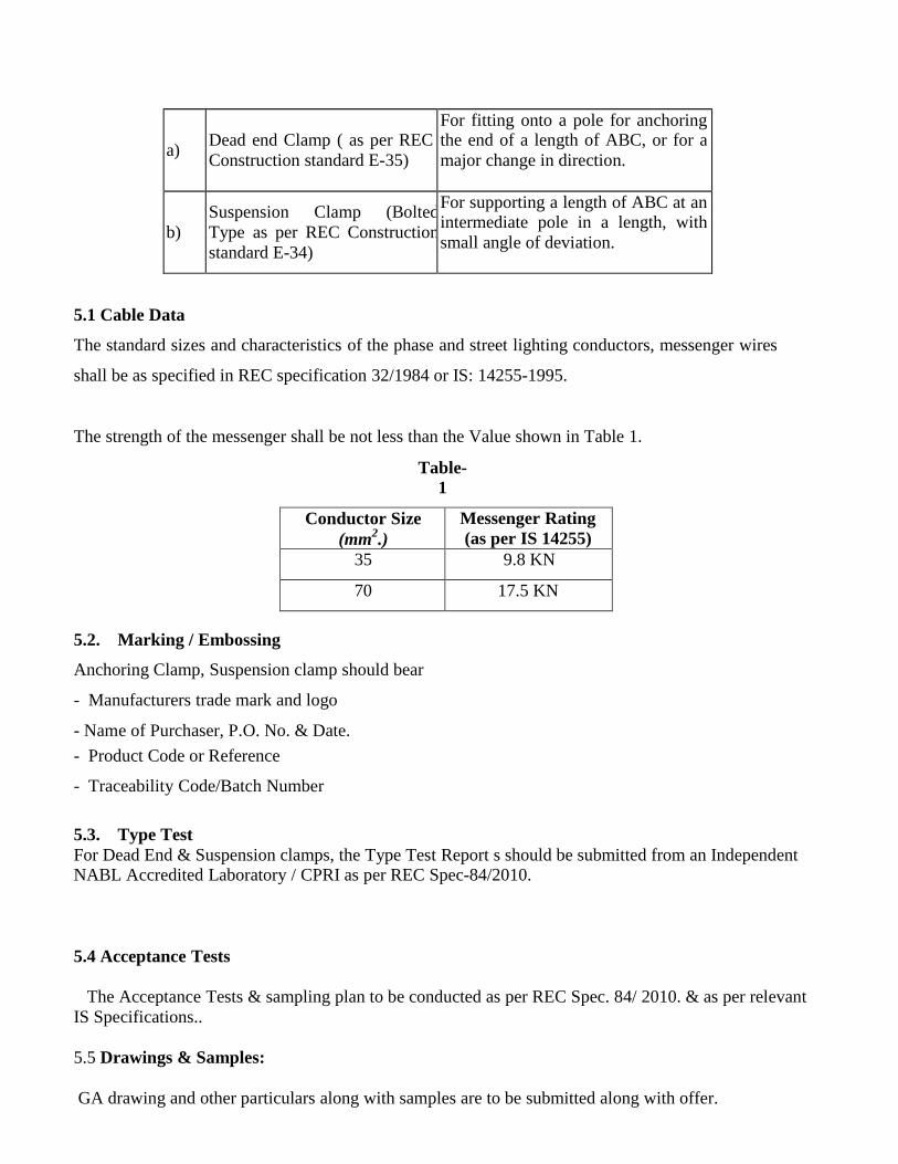
a)
Dead end Clamp ( as per REC
Construction standard E-35)
For fitting onto a pole for anchoring the end of a length of ABC, or for a
major change in direction.
b)
Suspension Clamp (Bolted
Type as per REC Construction
standard E-34)
For supporting a length of ABC at an intermediate pole in a length, with
small angle of deviation.
5.1 Cable Data
The standard sizes and characteristics of the phase and street lighting conductors, messenger wires
shall be as specified in REC specification 32/1984 or IS: 14255-1995.
The strength of the messenger shall be not less than the Value shown in Table 1.
Table-
1
Conductor Size
(mm2.)
Messenger Rating
(as per IS 14255)
35 9.8 KN
70 17.5 KN
5.2. Marking / Embossing
Anchoring Clamp, Suspension clamp should bear
- Manufacturers trade mark and logo
- Name of Purchaser, P.O. No. & Date.
- Product Code or Reference
- Traceability Code/Batch Number
5.3. Type Test
For Dead End & Suspension clamps, the Type Test Report s should be submitted from an Independent NABL Accredited Laboratory / CPRI as per REC Spec-84/2010.
5.4 Acceptance Tests
The Acceptance Tests & sampling plan to be conducted as per REC Spec. 84/ 2010. & as per relevant
IS Specifications..
5.5 Drawings & Samples:
GA drawing and other particulars along with samples are to be submitted along with offer.
6.0 EYE HOOKS
a) Eye hooks shall be as per REC construction standard E-35 (Type – A)
b) It should be made of forged hot dip galvanized steel as per IS-1570
c) The clamp corrosion resistance should conform to standards IS 2629 & IS 2633.
d) Minimum breaking Load should be 20 KN.
6.1 Type Test
For Eye hooks, the Type Test Report s should be submitted from an Independent NABL Accredited Laboratory / CPRI as REC Spec-32/1984 & 84/2010 and as per relevant IS Specifications.
6.2 Acceptance Tests
The Acceptance Tests & sampling plan to be conducted as per REC Spec. 32/ 1984. & 84/2010 and as
per relevant IS Specifications.
6.2 Drawings & Samples:
GA drawing and other particulars along with samples are to be submitted along with offer.
7.0 NEUTRAL CONNECTOR
a) The Neutral Connector shall be as per REC Construction standard E-36
b) It should be consist of corrosion resistant extruded Aluminum Alloy body suitable for
messenger wire as mentioned under clause-3 above.
7.1 Type Test
For Eye hooks, the Type Test Report s should be submitted from an Independent NABL Accredited Laboratory / CPRI as REC Spec-32/1984 & 84/2010 and as per relevant IS Specifications.
7.2 Acceptance Tests
The Acceptance Tests & sampling plan to be conducted as per REC Spec. 32/ 1984. & 84/2010 and as
per relevant IS Specifications.
7.3 Drawings & Samples:
GA drawing and other particulars along with samples are to be submitted along with offer.
GUARANTEED TECHNICAL PARTICULARS FOR INSULATION PIERSING CONNECTOR
Sl. No.
Description Guaranteed particulars to be submitted by the
Vendors along with offer
1 Name and address of the
Manufacturer
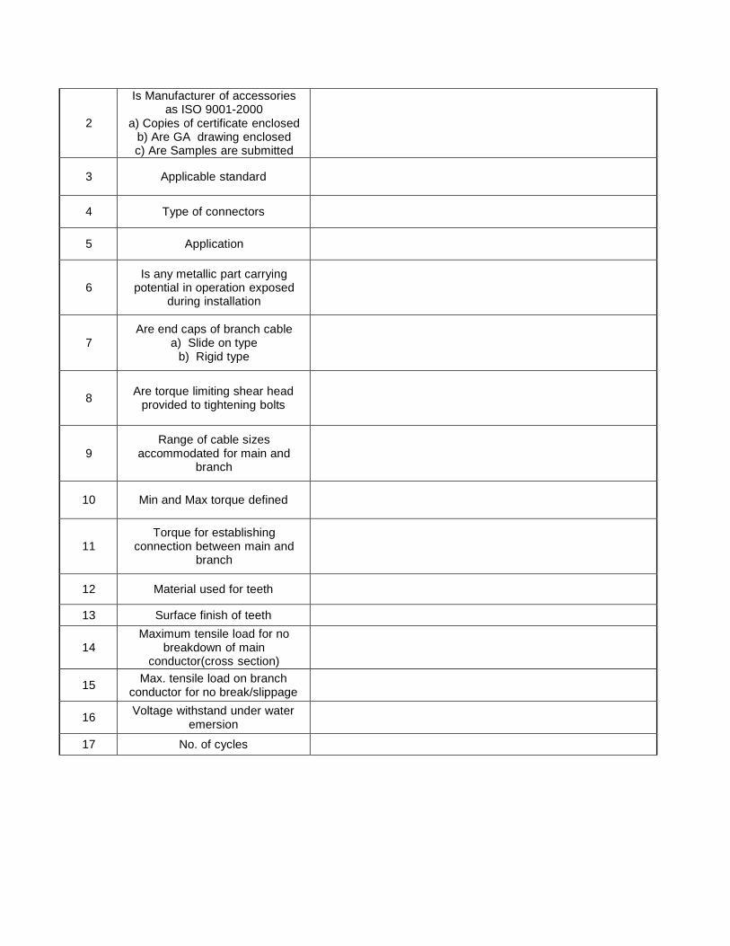
2
Is Manufacturer of accessories as ISO 9001-2000
a) Copies of certificate enclosed b) Are GA drawing enclosed c) Are Samples are submitted
3
Applicable standard
4
Type of connectors
5
Application
6
Is any metallic part carrying potential in operation exposed
during installation
7
Are end caps of branch cable a) Slide on type
b) Rigid type
8
Are torque limiting shear head
provided to tightening bolts
9
Range of cable sizes accommodated for main and
branch
10
Min and Max torque defined
11
Torque for establishing connection between main and
branch
12
Material used for teeth
13 Surface finish of teeth
14
Maximum tensile load for no breakdown of main
conductor(cross section)
15 Max. tensile load on branch
conductor for no break/slippage
16 Voltage withstand under water
emersion
17 No. of cycles
18 Max temp at each cycle
19 Marking and embossing on the
connector
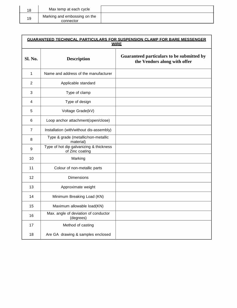
GUARANTEED TECHNICAL PARTICULARS FOR SUSPENSION CLAMP FOR BARE MESSENGER WIRE
Sl. No.
Description
Guaranteed particulars to be submitted by
the Vendors along with offer
1
Name and address of the manufacturer
2
Applicable standard
3
Type of clamp
4
Type of design
5
Voltage Grade(kV)
6
Loop anchor attachment(open/close)
7
Installation (with/without dis-assembly)
8 Type & grade (metallic/non-metallic
material)
9 Type of hot dip galvanizing & thickness
of Zinc coating
10
Marking
11
Colour of non-metallic parts
12
Dimensions
13
Approximate weight
14
Minimum Breaking Load (KN)
15
Maximum allowable load(KN)
16 Max. angle of deviation of conductor
(degrees)
17
18
Method of casting
Are GA drawing & samples enclosed
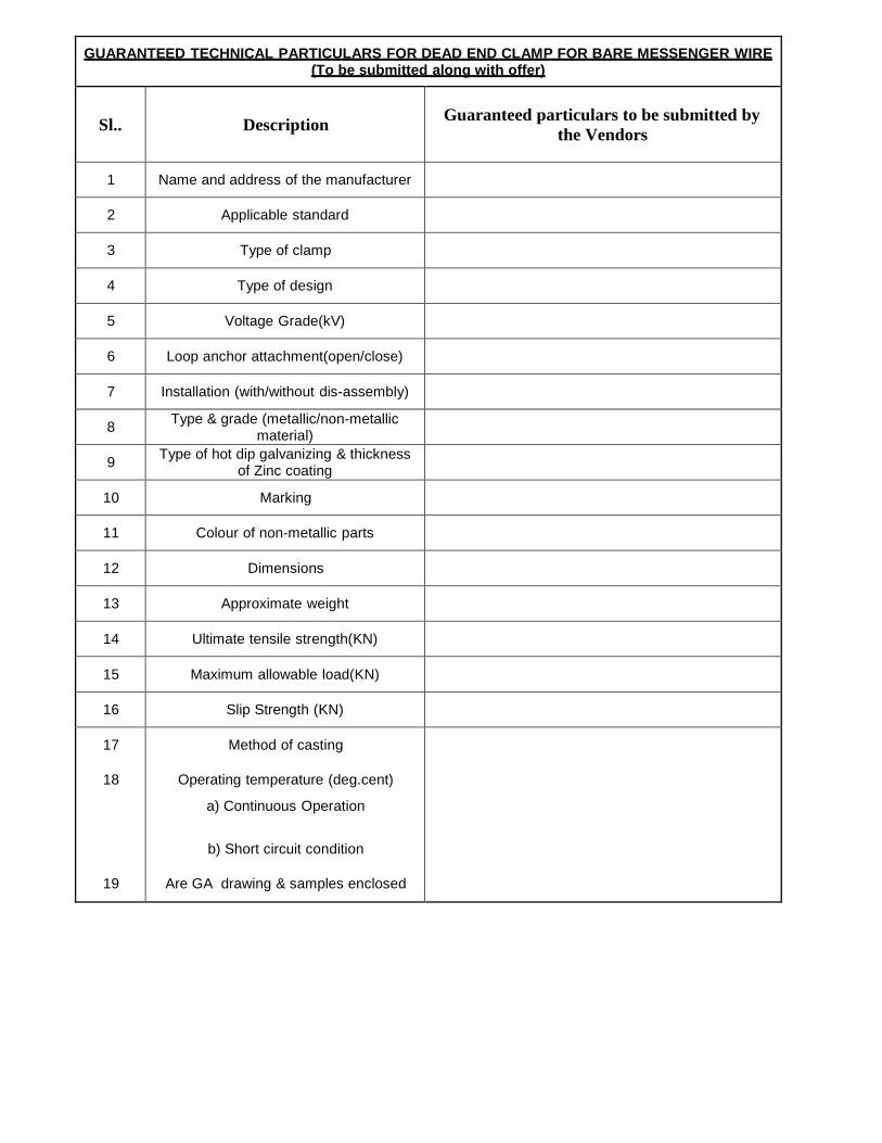
GUARANTEED TECHNICAL PARTICULARS FOR DEAD END CLAMP FOR BARE MESSENGER WIRE (To be submitted along with offer)
Sl..
Description
Guaranteed particulars to be submitted by
the Vendors
1
Name and address of the manufacturer
2
Applicable standard
3
Type of clamp
4
Type of design
5
Voltage Grade(kV)
6
Loop anchor attachment(open/close)
7
Installation (with/without dis-assembly)
8 Type & grade (metallic/non-metallic
material)
9 Type of hot dip galvanizing & thickness
of Zinc coating
10
Marking
11
Colour of non-metallic parts
12
Dimensions
13
Approximate weight
14
Ultimate tensile strength(KN)
15
Maximum allowable load(KN)
16
Slip Strength (KN)
17
18
19
Method of casting
Operating temperature (deg.cent)
a) Continuous Operation
b) Short circuit condition
Are GA drawing & samples enclosed
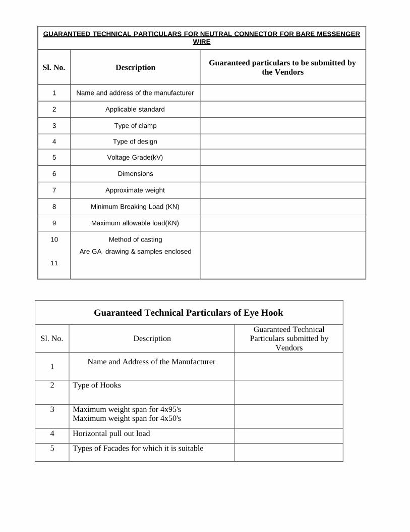
GUARANTEED TECHNICAL PARTICULARS FOR NEUTRAL CONNECTOR FOR BARE MESSENGER WIRE
Sl. No.
Description
Guaranteed particulars to be submitted by
the Vendors
1
Name and address of the manufacturer
2
Applicable standard
3
Type of clamp
4
Type of design
5
Voltage Grade(kV)
6
Dimensions
7
Approximate weight
8
Minimum Breaking Load (KN)
9
Maximum allowable load(KN)
10
11
Method of casting
Are GA drawing & samples enclosed
Guaranteed Technical Particulars of Eye Hook
Sl. No.
Description
Guaranteed Technical Particulars submitted by
Vendors
1
Name and Address of the Manufacturer
2 Type of Hooks
3 Maximum weight span for 4x95's Maximum weight span for 4x50's
4 Horizontal pull out load
5 Types of Facades for which it is suitable
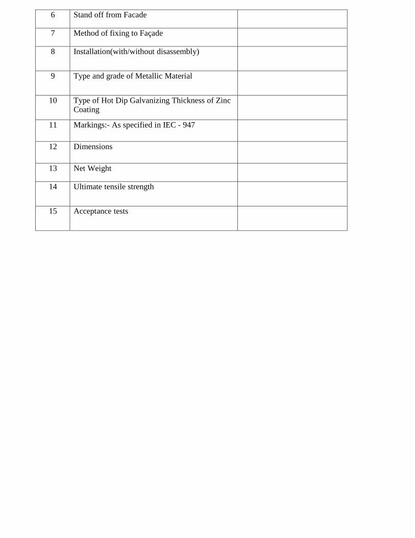
6 Stand off from Facade
7 Method of fixing to Façade
8 Installation(with/without disassembly)
9 Type and grade of Metallic Material
10 Type of Hot Dip Galvanizing Thickness of Zinc Coating
11 Markings:- As specified in IEC - 947
12 Dimensions
13 Net Weight
14 Ultimate tensile strength
15 Acceptance tests
TECHNICAL SPECIFICATION OF DANGER NOTICE PLATE :
The danger plate shall be affixed in a permanent manner on operating side of the panel, Substations, Distribution
Boards , Electric poles etc..
The danger notice plate shall indicate danger notice both in English and Odiya , English & Hindi and with a sign
of skull and bones.
The letter, the figure, the conventional skull and bones shall etc. shall be positioned on
the plate as per recommendations of IS : 2551-1982.
The said letter, the figure and the sign of skull and bones be painted in single red colour
as per IS : 5-1978.
Standards of Danger Plate: The Danger Notice Plates shall comply with IS:2551-1982 or the latest
amendment.
The following tests shall be carried out on Danger Plate:
I) Visual examination as per IS:2551-1982
II) Dimensional check as per IS:2551-1982
III) Test for weather proofness as per IS:8709-1977 (or its latest version)
Barbed Wire (2Ply) TECHNICAL SPECIFICATION FOR G.I. BARBED WIRE
STANDARDS:
Unless otherwise specified elsewhere in this specification, the rating as well as
performance and testing of the G.I.Barbed wire shall conform to the latest revisions
available at the time of placement of order of all the relevant standards but not
limited to as listed below.
IS:280:1978 Mild steel wire for general engineering purposes (third revision)
IS:1340:1977 Code of practice for chromate conversion coating of zinc and cadmium
coated articles and zinc base alloys (first revision)
IS:1521:1972 Method for tensile testing of steel wire (first revision)
IS:1755:1983 Method for wrapping test for metallic wire (first revision)
IS:2633:1986 Method for testing uniformity of coating of zinc coated articles(second revision)
IS:4826:1979 Hot dipped galvanized coating on round steel wires (first revision)
IS:12753:1989 Electro galvanized coatings on round steel wire - Specification
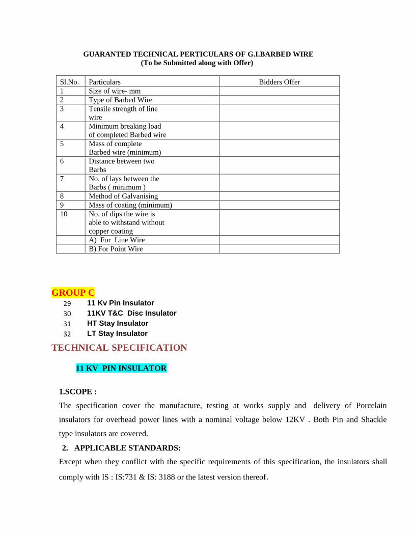
GUARANTED TECHNICAL PERTICULARS OF G.I.BARBED WIRE
(To be Submitted along with Offer)
Sl.No. Particulars Bidders Offer
1 Size of wire- mm
2 Type of Barbed Wire
3 Tensile strength of line
wire
4 Minimum breaking load
of completed Barbed wire
5 Mass of complete
Barbed wire (minimum)
6 Distance between two
Barbs
7 No. of lays between the
Barbs ( minimum )
8 Method of Galvanising
9 Mass of coating (minimum)
10 No. of dips the wire is
able to withstand without
copper coating
A) For Line Wire
B) For Point Wire
GROUP C 29 11 Kv Pin Insulator
30 11KV T&C Disc Insulator
31 HT Stay Insulator
32 LT Stay Insulator TECHNICAL SPECIFICATION
11 KV PIN INSULATOR
1.SCOPE :
The specification cover the manufacture, testing at works supply and delivery of Porcelain
insulators for overhead power lines with a nominal voltage below 12KV . Both Pin and Shackle
type insulators are covered.
2. APPLICABLE STANDARDS:
Except when they conflict with the specific requirements of this specification, the insulators shall
comply with IS : IS:731 & IS: 3188 or the latest version thereof.
3. GENERAL REQUIREMENTS:
The porcelain shall be sound, free from defects, thoroughly vitrified and smoothly glazed. The
design of the insulators shall be such that the stresses due to expansion and contraction in any
part of the insulator shall not lead to its deterioration. The glaze shall be brown in color for
insulators. The glaze shall cover the entire porcelain surface parts except those areas that serve as
supports during firing. The insulators shall be suitable for use with all Aluminum Conductor or
Copper conductor or ACSR upto 100 sq.mm. The insulators should withstand the conductor tension
the reversible wind load as well as the high frequency vibrations set due to wind.
4. SYSTEM CONDITIONS:
Frequency : 50 Hz
Nominal System Voltage : 11KV
Maximum System Voltage LT System : 12 KV
Minimum LT Voltage : 11KV
Power frequency one minute withstand Voltage(wet): 35KV
5. TYPE OF INSULATORS:
The standard Pin insulators shall be of designation Type –B of IS : 731 or its latest revision.
6. TESTS:
a. Type tests:
a) Visual examination
b) Verification of dimensions
c) Temperature cycle test
d) Dry one minute power frequency withstand test
e) Wet one minute power frequency withstand test
f) Mechanical strength test
g) Porosity test
6.2 Acceptance test:
The insulators, after having withstood the routine test shall be
subjected to the following acceptance tests in the order given below:
a) Verification of Dimensions.
b) Temperature cycle test
c) Mechanical strength test
d) Porosity test
6.3 Routine tests:
i) Visual examination
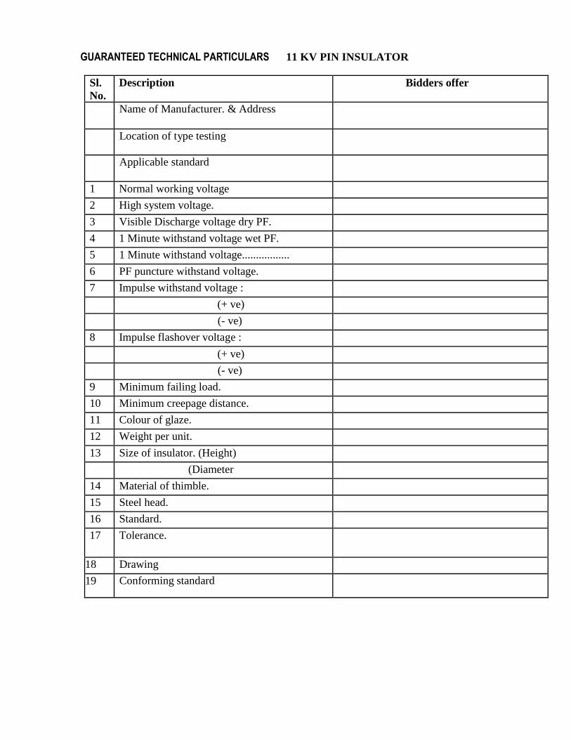
GUARANTEED TECHNICAL PARTICULARS 11 KV PIN INSULATOR
Sl.
No.
Description Bidders offer
Name of Manufacturer. & Address
Location of type testing
Applicable standard
1 Normal working voltage
2 High system voltage.
3 Visible Discharge voltage dry PF.
4 1 Minute withstand voltage wet PF.
5 1 Minute withstand voltage.................
6 PF puncture withstand voltage.
7 Impulse withstand voltage :
(+ ve)
(- ve)
8 Impulse flashover voltage :
(+ ve)
(- ve)
9 Minimum failing load.
10 Minimum creepage distance.
11 Colour of glaze.
12 Weight per unit.
13 Size of insulator. (Height)
(Diameter
)
14 Material of thimble.
15 Steel head.
16 Standard.
17 Tolerance.
18 Drawing
19 Conforming standard
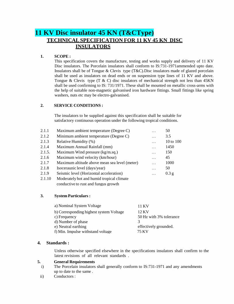
11 KV Disc insulator 45 KN (T&CType)
TECHNICAL SPECIFICATION FOR 11 KV 45 KN DISC
INSULATORS
1. SCOPE :
This specification covers the manufacture, testing and works supply and delivery of 11 KV
Disc insulators. The Porcelain insulators shall conform to IS:731-1971ammended upto date.
Insulators shall be of Tongue & Clevis type (T&C).Disc insulators made of glazed porcelain
shall be used as insulators on dead ends or on suspension type lines of 11 KV and above.
Tongue & Clevis type (T & C) disc insulators of mechanical strength not less than 45KN
shall be used confirming to IS: 731/1971. These shall be mounted on metallic cross-arms with
the help of suitable non-magnetic galvanised iron hardware fittings. Small fittings like spring
washers, nuts etc may be electro-galvanised.
2. SERVICE CONDITIONS :
The insulators to be supplied against this specification shall be suitable for
satisfactory continuous operation under the following tropical conditions.
2.1.1 Maximum ambient temperature (Degree C) … 50
2.1.2 Minimum ambient temperature (Degree C) … 3.5
2.1.3 Relative Humidity (%) … 10 to 100
2.1.4 Maximum Annual Rainfall (mm) … 1450
2.1.5. Maximum Wind pressure (kg/m.sq.) … 150
2.1.6 Maximum wind velocity (km/hour) … 45
2.1.7 Maximum altitude above mean sea level (meter) … 1000
2.1.8 Isoceraunic level (days/year) … 50
2.1.9 Seismic level (Horizontal acceleration) … 0.3 g
2.1.10 Moderately hot and humid tropical climate
conductive to rust and fungus growth
3. System Particulars :
a) Nominal System Voltage
11 KV
b) Corresponding highest system Voltage
c) Frequency
d) Number of phase
e) Neutral earthing
f) Min. Impulse withstand voltage
12 KV
50 Hz with 3% tolerance
3
effectively grounded.
75 KV
4. Standards :
Unless otherwise specified elsewhere in the specifications insulators shall confirm to the
latest revisions of all relevant standards .
5. General Requirements i) The Porcelain insulators shall generally conform to IS:731-1971 and any amendments
up to date to the same .
ii) Conductors :
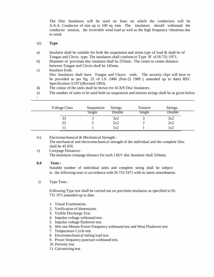
The Disc Insulators will be used on lines on which the conductors will be
A.A.A. Conductor of size up to 100 sq. mm. The insulators should withstand the
conductor tension, the reversible wind load as well as the high frequency vibrations due
to wind.
iii) Type
a) Insulator shall be suitable for both the suspension and strain type of load & shall be of
Tongue and Clevis type. The insulators shall conform to Type „B‟ of IS:731-1971.
b) Diameter of porcelain disc insulator shall be 255mm . The center to center distance
between Tongue and Clevis shall be 145mm.
c) Insulator Ends.
Disc Insulators shall have Tongue and Cleave ends. The security clips will have to
be provided as per fig. 25 of I.S. 2486 (Part-2) 1989 ( amended up to date) REC
Specification 3/1971(Revised 1993).
d) The colour of the units shall be brown for 45 KN Disc Insulators .
e) The number of units to be used both on suspension and tension strings shall be as given below
:
Voltage Class Suspension Strings Tension Strings.
Single Double Single Double
33 3 3x2 3 3x2 22 2 2x2 2 2x2
11 1 1x2 1 1x2
iv). Electromechanical & Mechanical Strength :
The mechanical and electromechanical strength of the individual and the complete Disc
shall be 45 KN.
v) Creepage Distances :
The minimum creepage distance for each 11KV disc Insulator shall 320mm.
6.0 Tests :
Suitable number of individual units and complete string shall be subject
to the following tests in accordance with IS:731/1971 with its latest amendments.
i) Type Tests :
Following Type test shall be carried out on porcelain insulators as specified in IS:
731 /971 amended up to date.
1. Visual Examination.
2. Verification of dimensions.
3. Visible Discharge Test.
4. Impulse voltage withstand test.
5. Impulse voltage flashover test.
6. Wet one Minute Power Frequency withstand test and West Flashover test. 7. Temperature Cycle test.
8. Electromechanical failing load test.
9. Power frequency puncture withstand test.
10. Porosity test.
11. Galvanizing test.
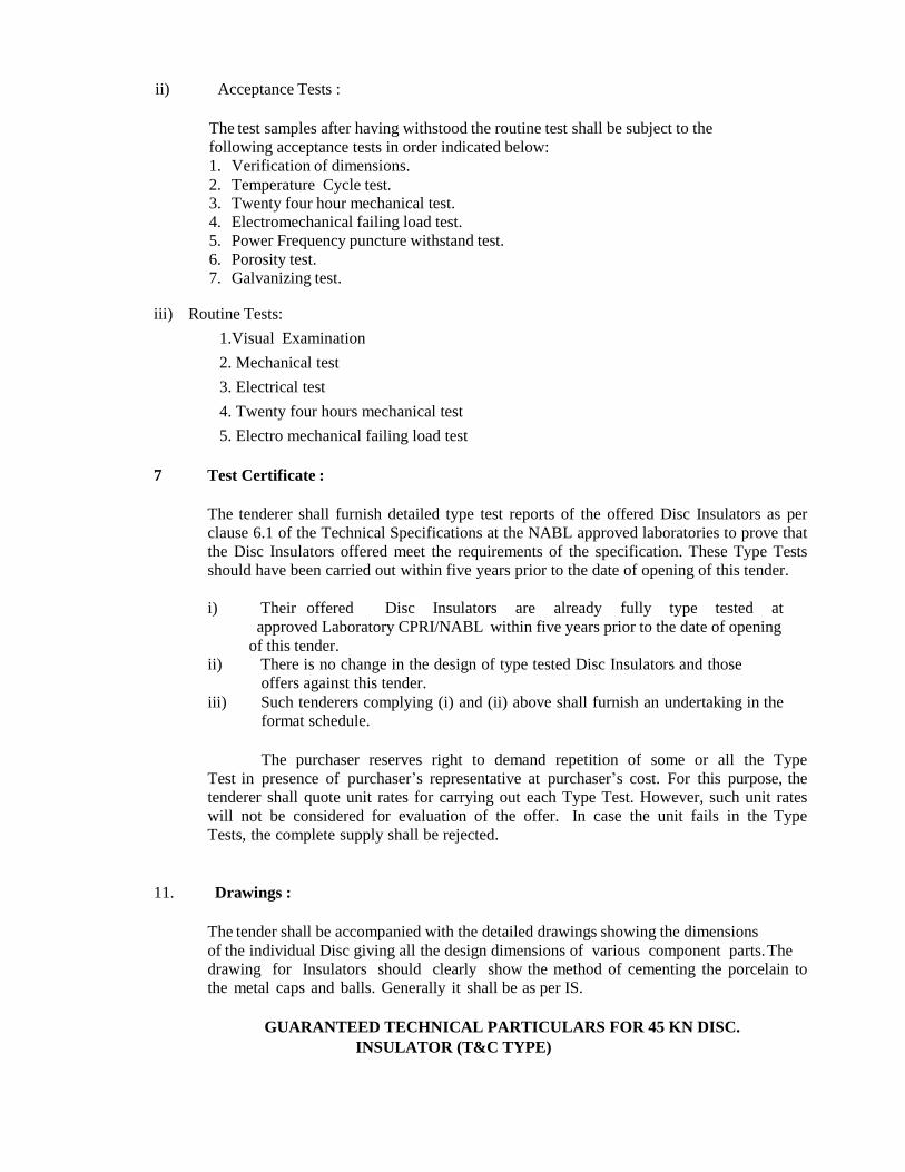
ii) Acceptance Tests :
The test samples after having withstood the routine test shall be subject to the
following acceptance tests in order indicated below:
1. Verification of dimensions.
2. Temperature Cycle test. 3. Twenty four hour mechanical test.
4. Electromechanical failing load test.
5. Power Frequency puncture withstand test.
6. Porosity test.
7. Galvanizing test.
iii) Routine Tests:
1.Visual Examination
2. Mechanical test
3. Electrical test
4. Twenty four hours mechanical test
5. Electro mechanical failing load test
7 Test Certificate :
The tenderer shall furnish detailed type test reports of the offered Disc Insulators as per
clause 6.1 of the Technical Specifications at the NABL approved laboratories to prove that
the Disc Insulators offered meet the requirements of the specification. These Type Tests
should have been carried out within five years prior to the date of opening of this tender.
i) Their offered Disc Insulators are already fully type tested at
approved Laboratory CPRI/NABL within five years prior to the date of opening
of this tender. ii) There is no change in the design of type tested Disc Insulators and those
offers against this tender.
iii) Such tenderers complying (i) and (ii) above shall furnish an undertaking in the
format schedule.
The purchaser reserves right to demand repetition of some or all the Type
Test in presence of purchaser‟s representative at purchaser‟s cost. For this purpose, the
tenderer shall quote unit rates for carrying out each Type Test. However, such unit rates
will not be considered for evaluation of the offer. In case the unit fails in the Type
Tests, the complete supply shall be rejected.
11. Drawings :
The tender shall be accompanied with the detailed drawings showing the dimensions
of the individual Disc giving all the design dimensions of various component parts. The
drawing for Insulators should clearly show the method of cementing the porcelain to
the metal caps and balls. Generally it shall be as per IS.
GUARANTEED TECHNICAL PARTICULARS FOR 45 KN DISC.
INSULATOR (T&C TYPE)
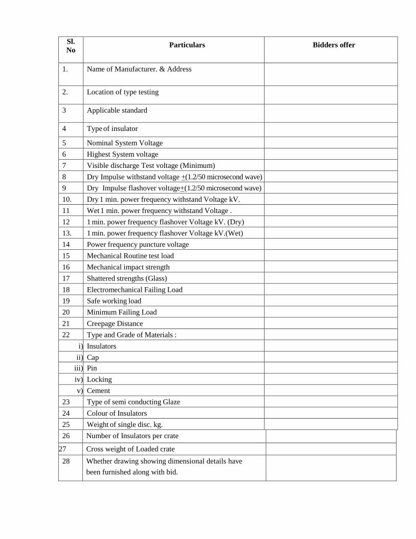
Sl.
No
Particulars
Bidders offer
1. Name of Manufacturer. & Address
2. Location of type testing
3 Applicable standard
4 Type of insulator
5 Nominal System Voltage
6 Highest System voltage
7 Visible discharge Test voltage (Minimum)
8 Dry Impulse withstand voltage +(1.2/50 microsecond wave)
9 Dry Impulse flashover voltage+(1.2/50 microsecond wave)
10. Dry 1 min. power frequency withstand Voltage kV.
11 Wet 1 min. power frequency withstand Voltage .
12 1 min. power frequency flashover Voltage kV. (Dry)
13. 1 min. power frequency flashover Voltage kV.(Wet)
14 Power frequency puncture voltage
15 Mechanical Routine test load
16 Mechanical impact strength
17 Shattered strengths (Glass)
18 Electromechanical Failing Load
19 Safe working load
20 Minimum Failing Load
21 Creepage Distance
22 Type and Grade of Materials :
i) Insulators
ii) Cap
iii) Pin
iv) Locking
v) Cement
23 Type of semi conducting Glaze
24 Colour of Insulators
25 Weight of single disc. kg.
26 Number of Insulators per crate
27 Cross weight of Loaded crate
28 Whether drawing showing dimensional details have
been furnished along with bid.
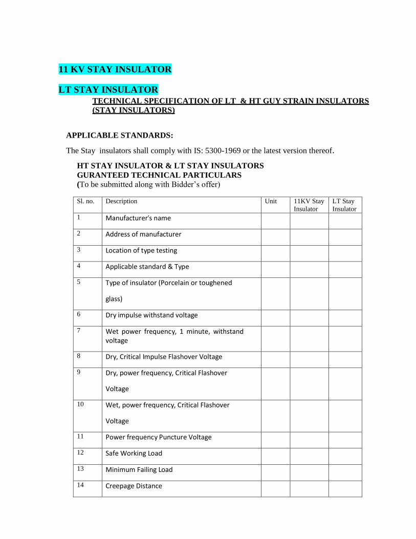
11 KV STAY INSULATOR
LT STAY INSULATOR
TECHNICAL SPECIFICATION OF LT & HT GUY STRAIN INSULATORS
(STAY INSULATORS)
APPLICABLE STANDARDS:
The Stay insulators shall comply with IS: 5300-1969 or the latest version thereof.
HT STAY INSULATOR & LT STAY INSULATORS
GURANTEED TECHNICAL PARTICULARS
(To be submitted along with Bidder‟s offer)
Sl. no. Description Unit 11KV Stay
Insulator
LT Stay
Insulator
1 Manufacturer’s name
2 Address of manufacturer
3 Location of type testing
4 Applicable standard & Type
5 Type of insulator (Porcelain or toughened
glass)
6 Dry impulse withstand voltage
7 Wet power frequency, 1 minute, withstand voltage
8 Dry, Critical Impulse Flashover Voltage
9 Dry, power frequency, Critical Flashover
Voltage
10 Wet, power frequency, Critical Flashover
Voltage
11 Power frequency Puncture Voltage
12 Safe Working Load
13 Minimum Failing Load
14 Creepage Distance
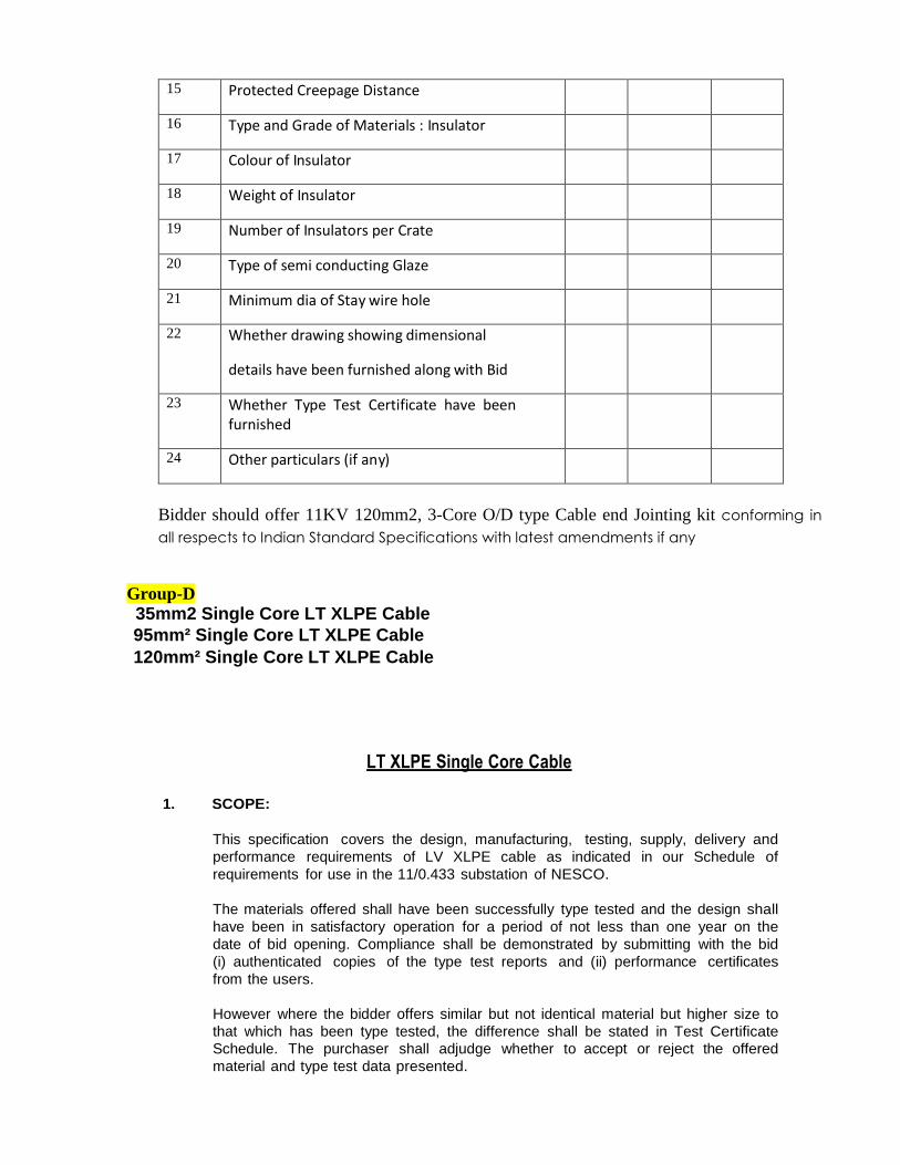
15 Protected Creepage Distance
16 Type and Grade of Materials : Insulator
17 Colour of Insulator
18 Weight of Insulator
19 Number of Insulators per Crate
20 Type of semi conducting Glaze
21 Minimum dia of Stay wire hole
22 Whether drawing showing dimensional
details have been furnished along with Bid
23 Whether Type Test Certificate have been furnished
24 Other particulars (if any)
Bidder should offer 11KV 120mm2, 3-Core O/D type Cable end Jointing kit conforming in
all respects to Indian Standard Specifications with latest amendments if any
Group-D
35mm2 Single Core LT XLPE Cable
95mm² Single Core LT XLPE Cable
120mm² Single Core LT XLPE Cable
LT XLPE Single Core Cable
1. SCOPE:
This specification covers the design, manufacturing, testing, supply, delivery and
performance requirements of LV XLPE cable as indicated in our Schedule of
requirements for use in the 11/0.433 substation of NESCO.
The materials offered shall have been successfully type tested and the design shall
have been in satisfactory operation for a period of not less than one year on the
date of bid opening. Compliance shall be demonstrated by submitting with the bid
(i) authenticated copies of the type test reports and (ii) performance certificates
from the users.
However where the bidder offers similar but not identical material but higher size to
that which has been type tested, the difference shall be stated in Test Certificate
Schedule. The purchaser shall adjudge whether to accept or reject the offered
material and type test data presented.
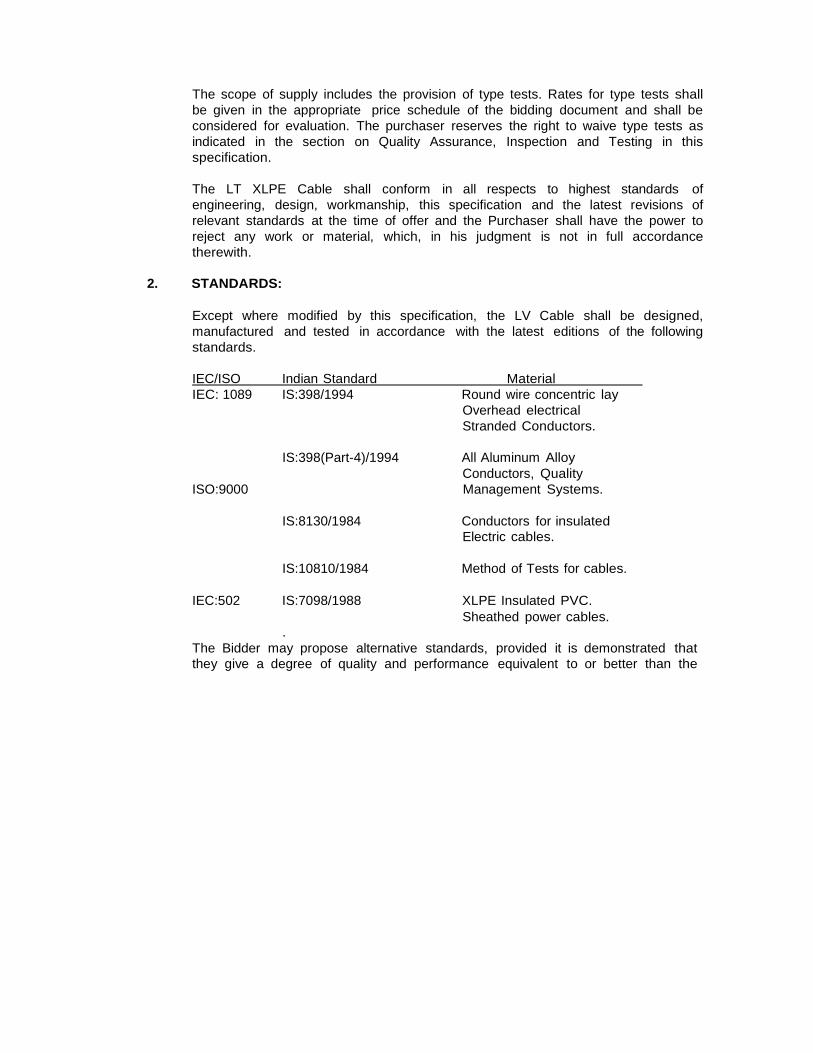
The scope of supply includes the provision of type tests. Rates for type tests shall
be given in the appropriate price schedule of the bidding document and shall be
considered for evaluation. The purchaser reserves the right to waive type tests as
indicated in the section on Quality Assurance, Inspection and Testing in this
specification.
The LT XLPE Cable shall conform in all respects to highest standards of
engineering, design, workmanship, this specification and the latest revisions of
relevant standards at the time of offer and the Purchaser shall have the power to
reject any work or material, which, in his judgment is not in full accordance
therewith.
2. STANDARDS:
Except where modified by this specification, the LV Cable shall be designed,
manufactured and tested in accordance with the latest editions of the following
standards.
IEC/ISO Indian Standard Material
IEC: 1089 IS:398/1994 Round wire concentric lay
Overhead electrical
Stranded Conductors.
IS:398(Part-4)/1994 All Aluminum Alloy
Conductors, Quality
ISO:9000 Management Systems.
IS:8130/1984 Conductors for insulated
Electric cables.
IS:10810/1984 Method of Tests for cables.
IEC:502 IS:7098/1988 XLPE Insulated PVC.
Sheathed power cables.
.
The Bidder may propose alternative standards, provided it is demonstrated that
they give a degree of quality and performance equivalent to or better than the
referenced standards. The purchaser shall adjudge whether to accept or reject any
standards.
In case of conflict the order of the precedence shall be (1) IEC or ISO standards,
(2) Indian Standards, (3) Other alternative standards. This list is not to be
considered exhaustive and reference to a particular standard or recommendation
in this specification does not relieve the Manufacturer or the necessity of providing
the goods complying with other relevant standards or recommendation.
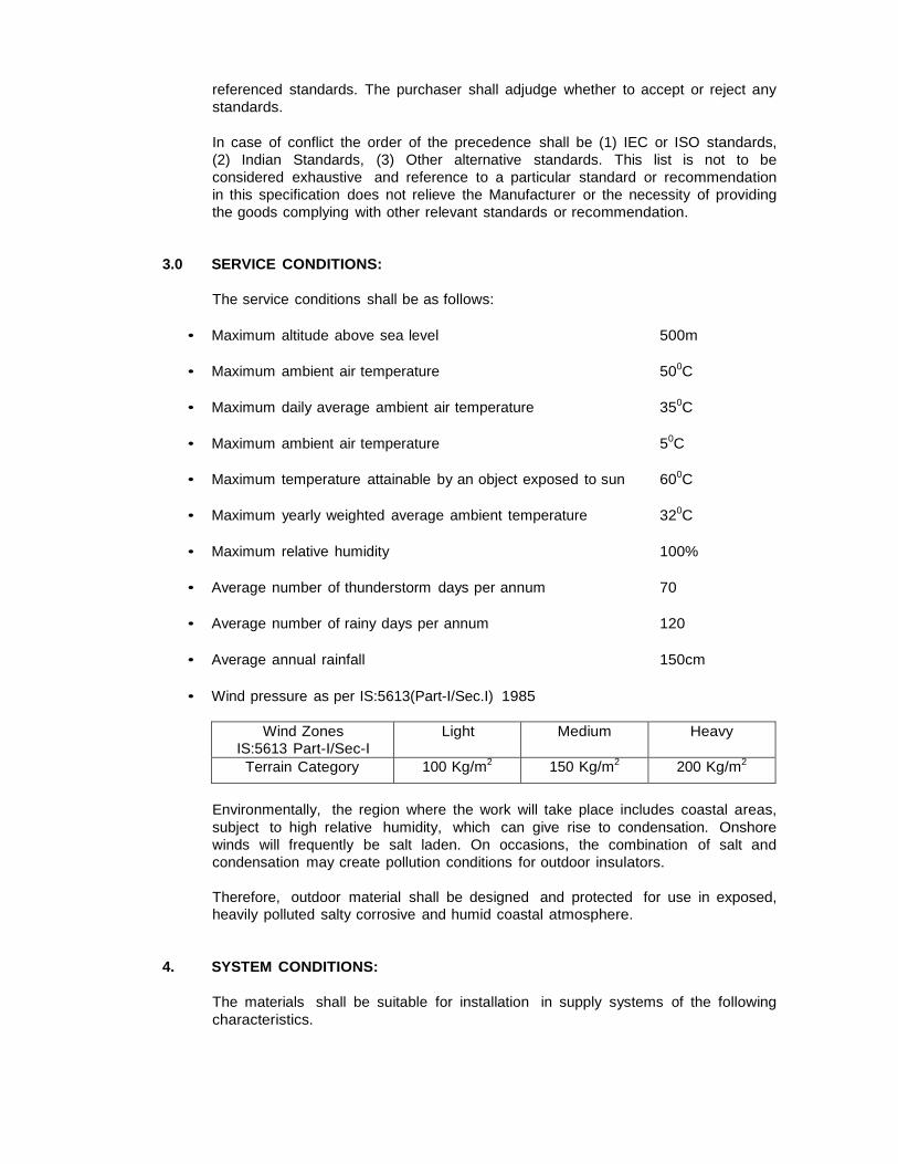
3.0 SERVICE CONDITIONS:
The service conditions shall be as follows:
• Maximum altitude above sea level 500m
• Maximum ambient air temperature 500C
• Maximum daily average ambient air temperature 350C
• Maximum ambient air temperature 50C
• Maximum temperature attainable by an object exposed to sun 600C
• Maximum yearly weighted average ambient temperature 320C
• Maximum relative humidity 100%
• Average number of thunderstorm days per annum 70
• Average number of rainy days per annum 120
• Average annual rainfall 150cm
• Wind pressure as per IS:5613(Part-I/Sec.I) 1985
Wind Zones
IS:5613 Part-I/Sec-I Light Medium Heavy
Terrain Category 100 Kg/m2 150 Kg/m2 200 Kg/m2
Environmentally, the region where the work will take place includes coastal areas,
subject to high relative humidity, which can give rise to condensation. Onshore
winds will frequently be salt laden. On occasions, the combination of salt and
condensation may create pollution conditions for outdoor insulators.
Therefore, outdoor material shall be designed and protected for use in exposed,
heavily polluted salty corrosive and humid coastal atmosphere.
4. SYSTEM CONDITIONS:
The materials shall be suitable for installation in supply systems of the following
characteristics.
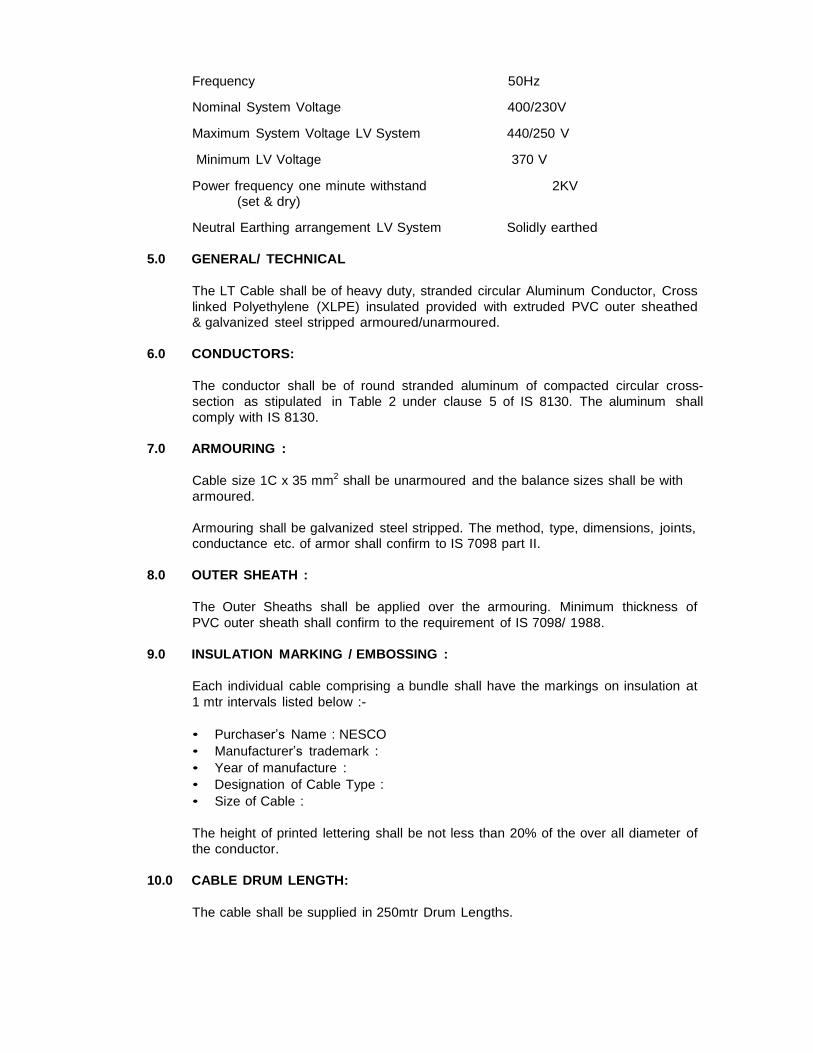
Frequency 50Hz
Nominal System Voltage 400/230V
Maximum System Voltage LV System 440/250 V
Minimum LV Voltage 370 V
Power frequency one minute withstand 2KV
(set & dry)
Neutral Earthing arrangement LV System Solidly earthed
5.0 GENERAL/ TECHNICAL
The LT Cable shall be of heavy duty, stranded circular Aluminum Conductor, Cross
linked Polyethylene (XLPE) insulated provided with extruded PVC outer sheathed
& galvanized steel stripped armoured/unarmoured.
6.0 CONDUCTORS:
The conductor shall be of round stranded aluminum of compacted circular cross-
section as stipulated in Table 2 under clause 5 of IS 8130. The aluminum shall
comply with IS 8130.
7.0 ARMOURING :
Cable size 1C x 35 mm2 shall be unarmoured and the balance sizes shall be with
armoured.
Armouring shall be galvanized steel stripped. The method, type, dimensions, joints,
conductance etc. of armor shall confirm to IS 7098 part II.
8.0 OUTER SHEATH :
The Outer Sheaths shall be applied over the armouring. Minimum thickness of
PVC outer sheath shall confirm to the requirement of IS 7098/ 1988.
9.0 INSULATION MARKING / EMBOSSING :
Each individual cable comprising a bundle shall have the markings on insulation at
1 mtr intervals listed below :-
• Purchaser’s Name : NESCO
• Manufacturer’s trademark :
• Year of manufacture :
• Designation of Cable Type :
• Size of Cable :
The height of printed lettering shall be not less than 20% of the over all diameter of
the conductor.
10.0 CABLE DRUM LENGTH:
The cable shall be supplied in 250mtr Drum Lengths.
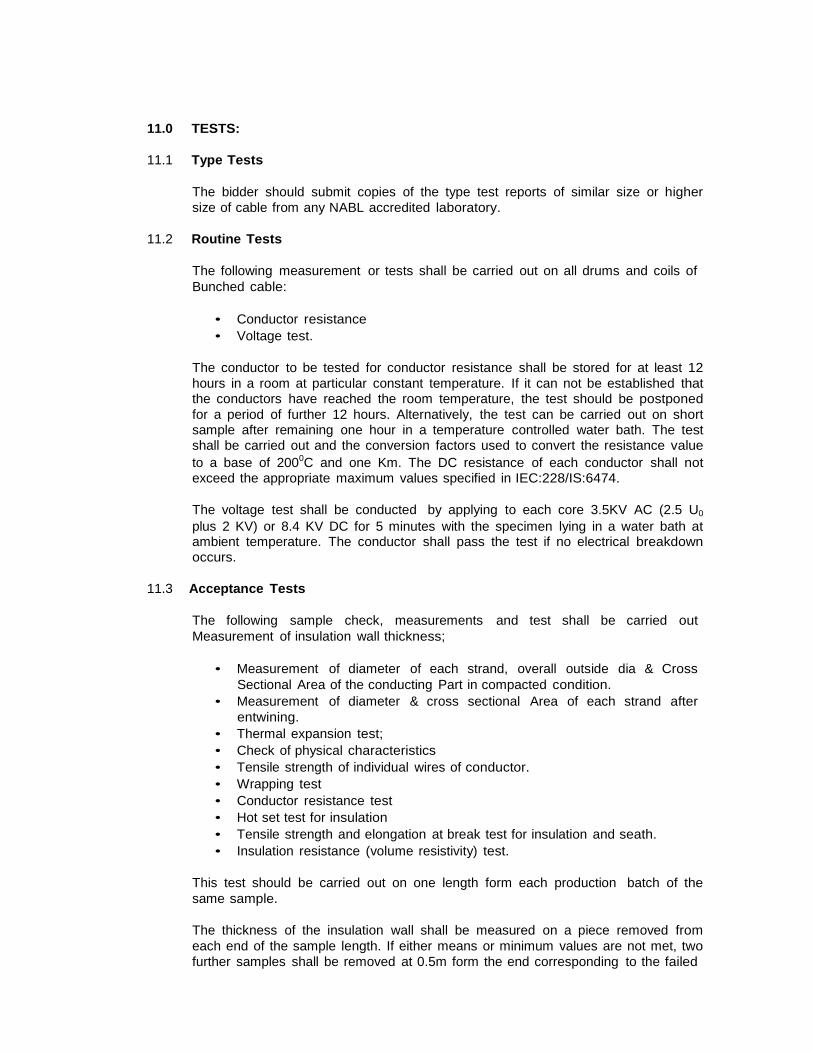
11.0 TESTS:
11.1 Type Tests
The bidder should submit copies of the type test reports of similar size or higher
size of cable from any NABL accredited laboratory.
11.2 Routine Tests
The following measurement or tests shall be carried out on all drums and coils of
Bunched cable:
• Conductor resistance
• Voltage test.
The conductor to be tested for conductor resistance shall be stored for at least 12
hours in a room at particular constant temperature. If it can not be established that the conductors have reached the room temperature, the test should be postponed
for a period of further 12 hours. Alternatively, the test can be carried out on short sample after remaining one hour in a temperature controlled water bath. The test shall be carried out and the conversion factors used to convert the resistance value
to a base of 2000C and one Km. The DC resistance of each conductor shall not exceed the appropriate maximum values specified in IEC:228/IS:6474.
The voltage test shall be conducted by applying to each core 3.5KV AC (2.5 U0
plus 2 KV) or 8.4 KV DC for 5 minutes with the specimen lying in a water bath at ambient temperature. The conductor shall pass the test if no electrical breakdown occurs.
11.3 Acceptance Tests
The following sample check, measurements and test shall be carried out
Measurement of insulation wall thickness;
• Measurement of diameter of each strand, overall outside dia & Cross
Sectional Area of the conducting Part in compacted condition.
• Measurement of diameter & cross sectional Area of each strand after
entwining.
• Thermal expansion test;
• Check of physical characteristics
• Tensile strength of individual wires of conductor.
• Wrapping test
• Conductor resistance test
• Hot set test for insulation
• Tensile strength and elongation at break test for insulation and seath.
• Insulation resistance (volume resistivity) test.
This test should be carried out on one length form each production batch of the
same sample.
The thickness of the insulation wall shall be measured on a piece removed from
each end of the sample length. If either means or minimum values are not met, two
further samples shall be removed at 0.5m form the end corresponding to the failed
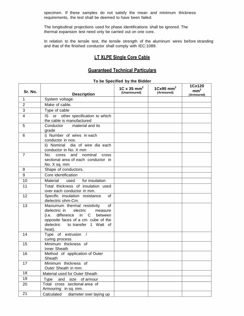
specimen. If these samples do not satisfy the mean and minimum thickness
requirements, the test shall be deemed to have been failed.
The longitudinal projections used for phase identifications shall be ignored. The
thermal expansion test need only be carried out on one core.
In relation to the tensile test, the tensile strength of the aluminum wires before stranding
and that of the finished conductor shall comply with IEC:1089.
LT XLPE Single Core Cable
Guaranteed Technical Particulars
To be Specified by the Bidder
Sr. No.
Description
1C x 35 mm2
(Unarmoured) 1Cx95 mm2
(Armoured)
1Cx120
mm2
(Armoured) 1 System voltage.
2 Make of cable.
3 Type of cable
4 IS or other specification to which
the cable is manufactured
5 Conductor material and its
grade
6 i) Number of wires in each
conductor in nos.
ii) Nominal dia of wire dia each
conductor in No. X mm
7 No. cores and nominal cross
sectional area of each conductor in
No. X sq. mm
8 Shape of conductors.
9 Core identification
10 Material used for insulation
11 Total thickness of insulation used
over each conductor in mm.
12 Specific insulation resistance of
dielectric ohm-Cm.
13 Maxiumum thermal resistivity of
dielectric in electric measure
(i.e. difference in C between
opposite faces of a cm. cube of the
dielectric to transfer 1 Watt of
heat).
14 Type of extrusion /
curing process
15 Minimum thickness of
Inner Sheath
16 Method of application of Outer
Sheath
17 Minimum thickness of
Outer Sheath in mm.
18 Material used for Outer Sheath
19 Type and size of armour
20 Total cross sectional area of Armouring in sq. mm.
21 Calculated diameter over laying up
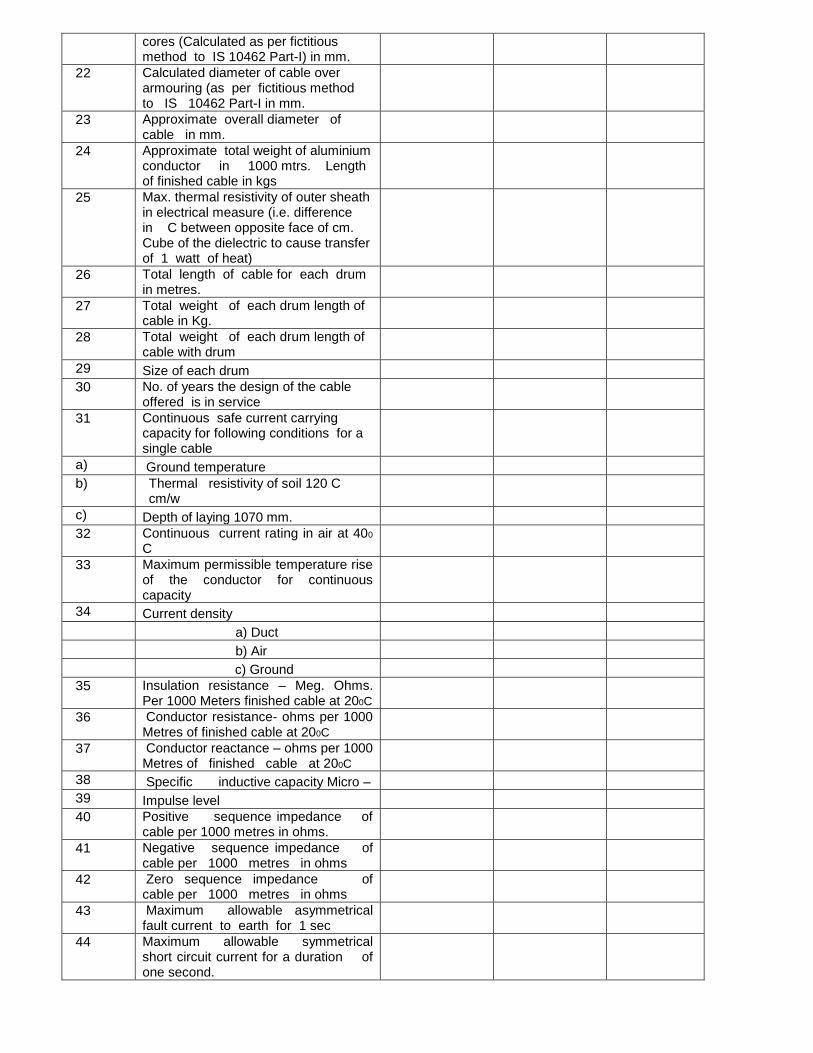
cores (Calculated as per fictitious method to IS 10462 Part-I) in mm.
22 Calculated diameter of cable over armouring (as per fictitious method to IS 10462 Part-I in mm.
23 Approximate overall diameter of cable in mm.
24 Approximate total weight of aluminium conductor in 1000 mtrs. Length of finished cable in kgs
25 Max. thermal resistivity of outer sheath in electrical measure (i.e. difference in C between opposite face of cm. Cube of the dielectric to cause transfer of 1 watt of heat)
26 Total length of cable for each drum in metres.
27 Total weight of each drum length of cable in Kg.
28 Total weight of each drum length of cable with drum
29 Size of each drum
30 No. of years the design of the cable offered is in service
31 Continuous safe current carrying capacity for following conditions for a single cable
a) Ground temperature
b) Thermal resistivity of soil 120 C cm/w
c) Depth of laying 1070 mm.
32 Continuous current rating in air at 400
C
33 Maximum permissible temperature rise of the conductor for continuous capacity
34 Current density
a) Duct
b) Air
c) Ground
35 Insulation resistance – Meg. Ohms. Per 1000 Meters finished cable at 200C
36 Conductor resistance- ohms per 1000 Metres of finished cable at 200C
37 Conductor reactance – ohms per 1000 Metres of finished cable at 200C
38 Specific inductive capacity Micro –
39 Impulse level
40 Positive sequence impedance of cable per 1000 metres in ohms.
41 Negative sequence impedance of cable per 1000 metres in ohms
42 Zero sequence impedance of cable per 1000 metres in ohms
43 Maximum allowable asymmetrical fault current to earth for 1 sec
44 Maximum allowable symmetrical short circuit current for a duration of one second.
11KV 120mm² 3-Core XLPE insulated overhead cables:
Bidder should offer 11KV 120mm2 3 Core XLPE insulated overhead cables conforming in all respects
to Indian Standard Specifications with latest amendments if any,