the apri 4 (accident phenomena of risk importance
TRANSCRIPT

The APRI 4 (Accident Phenomena of Risk Importance) research project isaccomplished by:
• Swedish Nuclear Power Inspectorate
• Ringhals AB
• OKG Aktiebolag
• Forsmarks Kraftgrupp AB
• Barsebäck Kraft AB
• Teollisuuden Voima Oy (TVO)
and supervised by the Project Board, consisting of:
OKG Aktiebolag Mauritz Gärdinge, chairmanSwedish Nuclear Power Inspectorate Oddbjörn SandervågRinghals AB Anders HenochForsmarks Kraftgrupp AB Ingvar BerglundBarsebäcks Kraft AB Erik LarsenTVO Heikki Sjövall


Contents
Abstract v
1 Introduction 1
1.1 Study objectives and workscope . . . . . . . . . . . . . . . . . . . . . . . 2
1.2 References . . . . . . . . . . . . . . . . . . . . . . . . . . . . . . . . . . . 3
2 Task 1: A general review of the phenomenology of a steam explosion during apostulated severe accident in nuclear power plants 4
2.1 General picture on MFCI . . . . . . . . . . . . . . . . . . . . . . . . . . . 4
2.1.1 Fuel Coolant Interaction (FCI) . . . . . . . . . . . . . . . . . . . . 5
2.2 Molten fuel-coolant premixing . . . . . . . . . . . . . . . . . . . . . . . . 7
2.2.1 Status of current research and recent results . . . . . . . . . . . . . 7
2.2.2 Inter-relations and uncertainties of molten fuel-coolant premixing . 9
2.2.3 Self-limiting mechanisms in melt-water premixing . . . . . . . . . 11
2.3 Molten fuel-coolant triggering . . . . . . . . . . . . . . . . . . . . . . . . 12
2.3.1 Status of current research and recent results . . . . . . . . . . . . . 12
2.3.2 Triggering experiments . . . . . . . . . . . . . . . . . . . . . . . . 14
2.3.3 Analytical work on triggering . . . . . . . . . . . . . . . . . . . . 17
2.3.4 Conclusions . . . . . . . . . . . . . . . . . . . . . . . . . . . . . . 18
i
2.4 Results from steam explosion experiments with different melt materials . . 19
2.5 Computational investigation of steam explosion . . . . . . . . . . . . . . . 20
2.5.1 PM-ALPHA and ESPROSE.m codes . . . . . . . . . . . . . . . . 20
2.5.2 MC3D code . . . . . . . . . . . . . . . . . . . . . . . . . . . . . . 22
2.5.3 Computations of the KROTOS tests with the codes COMETA, TEXASand SEURBNUK/EURDYN . . . . . . . . . . . . . . . . . . . . . 23
2.6 Summary . . . . . . . . . . . . . . . . . . . . . . . . . . . . . . . . . . . 24
2.6.1 Premixing/Quenching . . . . . . . . . . . . . . . . . . . . . . . . 24
2.6.2 Triggering-Propagating-Expansion . . . . . . . . . . . . . . . . . . 25
2.7 References . . . . . . . . . . . . . . . . . . . . . . . . . . . . . . . . . . . 26
3 Task 2. Ex-vessel steam explosion for the Swedish and Finnish BWRs and itsimpact on the melt coolability 30
3.1 Chapter objectives . . . . . . . . . . . . . . . . . . . . . . . . . . . . . . . 30
3.2 A review on the assessment of ex-vessel steam explosion for ABB BWRplants by the PM-ALPHA and ESPROSE.m codes . . . . . . . . . . . . . 31
3.2.1 Structural response of containment to dynamical loading . . . . . . 31
3.2.2 Previous assessment of ex-vessel steam explosions in the ABBBWR plants . . . . . . . . . . . . . . . . . . . . . . . . . . . . . . 34
3.2.3 Summary . . . . . . . . . . . . . . . . . . . . . . . . . . . . . . . 37
3.3 Limiting mechanisms and assessment methodology . . . . . . . . . . . . . 38
3.3.1 Limiting mechanisms . . . . . . . . . . . . . . . . . . . . . . . . . 38
3.3.2 Failure behavior of reactor pressure vessel . . . . . . . . . . . . . . 38
3.3.3 Metallic melt discharge to the drywell water pool . . . . . . . . . . 39
3.3.4 Steam explosion potential . . . . . . . . . . . . . . . . . . . . . . 40
3.4 Effect of steam explosion on debris bed formation . . . . . . . . . . . . . . 43
ii
3.4.1 Background on ex-vessel debris bed formation and coolability . . . 43
3.4.2 The effect of a steam explosion on debris bed characteristics . . . . 44
3.4.3 Coolability of inhomogeneous debris bed . . . . . . . . . . . . . . 44
3.4.4 Summary . . . . . . . . . . . . . . . . . . . . . . . . . . . . . . . 46
3.5 Effect of the ex-vessel water pool parameters on debris coolability . . . . . 46
3.5.1 Effect of the water pool parameters . . . . . . . . . . . . . . . . . 46
3.5.2 Current knowledge and uncertainties . . . . . . . . . . . . . . . . . 47
3.5.3 Quantification of ex-vessel debris coolability . . . . . . . . . . . . 49
3.5.4 Summary . . . . . . . . . . . . . . . . . . . . . . . . . . . . . . . 52
3.6 References . . . . . . . . . . . . . . . . . . . . . . . . . . . . . . . . . . . 52
4 Task 3: Assessment of steam explosions in the Swedish and Finnish BWRplants 55
4.1 Chapter objectives and approach . . . . . . . . . . . . . . . . . . . . . . . 55
4.2 Assessment of energetics of a steam explosion . . . . . . . . . . . . . . . . 55
4.2.1 Energetics of a steam explosion . . . . . . . . . . . . . . . . . . . 59
4.3 Evaluation of uncertainties in the assessment of steam explosions in theABB BWR plants . . . . . . . . . . . . . . . . . . . . . . . . . . . . . . 64
4.4 Benchmark calculations . . . . . . . . . . . . . . . . . . . . . . . . . . . . 66
4.5 Results of probabilistic assessment of premixing . . . . . . . . . . . . . . . 68
4.5.1 Oxidic melt release scenario O-1 . . . . . . . . . . . . . . . . . . . 68
4.5.2 Metallic melt release scenario M-1 . . . . . . . . . . . . . . . . . . 72
4.6 Results of probabilistic assessment of steam explosion energetics . . . . . . 75
4.6.1 Oxidic-melt release scenario O-1 . . . . . . . . . . . . . . . . . . . 75
4.6.2 Metallic-melt release scenario M-1 . . . . . . . . . . . . . . . . . 76
iii
4.7 Sensitivity analysis . . . . . . . . . . . . . . . . . . . . . . . . . . . . . . 77
4.7.1 Cases O-2: Oxidic melt flow rate . . . . . . . . . . . . . . . . . . . 78
4.7.2 Cases O-3 and O-4: Water pool depth . . . . . . . . . . . . . . . . 79
4.7.3 Case M-2: High melt superheat . . . . . . . . . . . . . . . . . . . 80
4.7.4 Case M-3: High melt superheat, lower melt flowrate . . . . . . . . 81
4.8 Series of explosions . . . . . . . . . . . . . . . . . . . . . . . . . . . . . . 82
4.8.1 Physical picture and current knowledge . . . . . . . . . . . . . . . 82
4.8.2 Evaluation of uncertainties and assessment . . . . . . . . . . . . . 83
4.9 Geometry effect . . . . . . . . . . . . . . . . . . . . . . . . . . . . . . . . 85
4.9.1 Geometrical characteristics . . . . . . . . . . . . . . . . . . . . . . 85
4.9.2 Geometry effects on steam explosion . . . . . . . . . . . . . . . . 86
4.10 Chapter summary . . . . . . . . . . . . . . . . . . . . . . . . . . . . . . . 86
4.11 References . . . . . . . . . . . . . . . . . . . . . . . . . . . . . . . . . . . 88
5 Task 4: Remaining uncertainties and future work 92
5.1 Chapter objectives and approach . . . . . . . . . . . . . . . . . . . . . . . 92
5.2 Melt-vessel interactions and melt discharge conditions . . . . . . . . . . . 92
5.3 Molten fuel-coolant interactions . . . . . . . . . . . . . . . . . . . . . . . 93
5.4 Debris coolability . . . . . . . . . . . . . . . . . . . . . . . . . . . . . . . 93
5.5 Summary . . . . . . . . . . . . . . . . . . . . . . . . . . . . . . . . . . . 94
6 Concluding remarks 95
iv
Abstract
The objective of the present study is to perform a critical review of ex-vessel steam explo-sion in Swedish and Finnish reactor containments in a hypothetical severe accident. Thereview performed is related to a broader program funded by APRI whose focus is relatedto severe accidents.
A critical review of the current knowledge base on the subject is performed, includingthose results obtained from other studies and assessments conducted earlier under aus-pice of APRI. Several limiting mechanisms which may significantly impact the assessmentof steam explosion loads are identified, taking into account specific reactor-design featuresand accident progression scenarios. In addition, generic discussion is provided on the effectof melt physical properties on the steam explosion energetics. Thermal hydraulic condi-tions of pre-mixture and its explosivity are evaluated using models and methods developedby the researchers at Royal Institute of Technology (RIT).
The report includes a wealth of information on details with respect to quantificationof vessel melt sources for ex-vessel FCIs; and with respect to the models of steam explo-sion premixing, triggerability and explosivity employed in the present assessment. Theseand other models e.g. on vessel failure, melt jet fragmentation etc. are products of thecontinuing research conducted at the Division of Nuclear Power Safety at RIT.
The general conclusion of the present study can be summarized as:
� Though substantial progress have been made in premixing research verifying themixing limit concept, there is still a need to improve jet breakup models and validatethe existing models against melt jet experiments.
� The understanding of the triggering mechanisms is still very pool. Though variousanalytical models have been developed based on the thermal detonation concepts, theneed still exists in both experimental and analytical research to understand better thedroplet fragmentation during the explosion or propagation phase, to develop and/orimprove fine fragmentation models, and to assess these models for use in reactorapplications.
� The effects of a steam explosion of large or small yield on the debris coolability havebeen assessed, a low-porosity deep debris bed, which may be hard to cool, may be
v

generated.
� An engineering assessment of the steam explosion energetics has been performed.The assessment covers a broader scope of scenarios of ex-vessel FCIs, i.e. includingmetallic-melt release scenarios. Results of the assessment indicate that the dynamic-loadings resulting from ex-vessel steam explosions in the ABB BWR plants may besmaller than the values predicted in a previous assessment.
vi
Chapter 1
Introduction
Much research has been performed in the last 20 years on energetic steam explosions. Themain focus of the study has been on in-vessel steam explosions caused by a melt masspouring from the core into the vessel water pool. The probability of a large in-vessel steamexplosion, which could fail the containment (�-mode failure), has recently been judged tobe extremely small (see e.g. Theofanous, 1995, Turland et al., 1993 and Speis and Basu,1997).
The ex-vessel steam explosion remains to be a critical issue since it could cause earlyfailure for some containments. Such a hypothetical situation may arise in the newer ABBboiling water reactor (BWR) plants, which are located in Sweden and Finland. These plantsemploy a severe accident management procedure, in which a deep, highly-subcooled, waterpool is established under the vessel, as soon as it becomes clear that the water level in thecore may fall below the top of the fuel. The motivation for this strategy is the engineeringjudgement that the core melt jet will break up during its passage through the water and thatthe particles formed can be cooled permanently within the water pool. The success of thisprocedure is also predicated upon the judgement that a large steam explosion, which couldthreaten the containment integrity during the melt-water interaction, will not occur. Thecurrent knowledge base indicates that an ex-vessel steam explosion event may have a lowerprobability than in some previous evaluations (Sehgal et al. 1999), however, it cannot, yet,be excluded.
Breakup of melt jets, which is a precursor of a steam explosion generates small sizeparticles. In addition, if a steam explosion occurs and involves even a hundred kilogramsof melt, there will be a large number of submicron size particles, which could be levitatedby the steam generation and would settle down later on the debris bed initially formed.The breakup and the fragmentation process could result in a deep, stratified low porositydebris bed which would be very difficult to cool in the pool. The decay heat generatedin the debris bed could, in time, remelt the debris bed, resulting in attack on the concretesubstrate, which in the case of some of the Swedish BWR containment would attack thepenetrations in the basemat, although some protection has been provided with covers back-
1
fitted in the dry well.
The Swedish and Finnish BWR dry wells have construction details which may be vul-nerable to an energetic steam explosion. In the TVO plant, the lower dry well contains thepersonal access door which is not as strong as the walls of the dry well. There are plantspecific vulnerabilities in other plants as well. For a postulated large steam explosion, theimpulse loads may be large enough to displace the dry well walls which support the vesseland the condensation pool. Thus the evolution of structural loading of the specific dry wellsalso becomes an important part of the study of risks of steam explosions for the Swedishand Finnish BWRs.
In this critical review of the steam explosions, we will confine ourselves to those aspectsof the phenomenology of steam explosions, which are important for the Swedish and FinishBWRs. However, we will not review structural response, since our competence does not,particularly, extend to those aspects. We suggest that response of specific dry wells in theseplants to dynamic loads imposed by postulated steam explosions be conducted separately.
1.1 Study objectives and workscope
The details of the workscope is provided in the form of tasks below. The study will befocused primarily, on the ex-vessel steam explosions and, in particular, on the probabilityof their occurrence and the most probable dynamic loadings they may generate for theSwedish and Finnish BWRs containments.
Task 1
A review of the recent and significant literature will be performed to gather knowledgeof the state of the art on all steam explosion phenomena. This review will employ publishedand unpublished information and will update the previous studies. Unfortunately, most ofthe previous studies are directed towards the conditions of the in-vessel steam explosions,i.e. saturated pools at somewhat elevated pressures. In this task the emphasis will be on,large depth, subcooled to saturated water pools at pressure level of up to 5 bars and coriummelt jets discharged from the vessel, which would start with small diameters but grow to belarge diameter. Various possible corium compositions and the sequences of the dischargeof the compositions from the vessel will be considered.
Task 2
A review of the results of any ex-vessel steam explosion studies which have relevanceto the Swedish and Finnish BWRs. In this context results of these studies with respectto the coolability issue will also be reviewed. Any conclusions reported, so far, will beexamined critically.
2
Task 3
This task and the next task will be concerned with the resolution of the ex-vessel steamexplosion issue. In this task the open issues that remain to be resolved in the steam ex-plosion phenomenology will be described and examined critically. Their impact on theprobability of occurrance and the consequences of the ex-vessel steam explosions in theSwedish and Finnish plants will be assessed.
Task 4
In this task research work that could provide the requisite insight and information toresolve the remaining issues in the steam explosion phenomena will be examined. Theobjectives will be to reduce the probabilities and consequences of steam explosions to theextent desired.
1.2 References
Theofanous, T.G., ”The Study of Steam Explosions in Nuclear Systems”, Nuclear Engi-neering Design, v. 155, pp. 1-26, 1995.
Turland et al., ”Quantification of the Probability of Containment Failure Caused by In-Vessel Steam Explosion for the Sizwell B PWR”, CSNI Specialist Meeting on FuelCoolant Interactions, Santa Barbara, CA, 1993.
Speis, T.P. and Basu, S., ”Fuel Coolant Interaction (FCI) Phenomena in Reactor Safety:Current Understanding and Future Research Needs” Proceedings of the OECD/CSNI/NEASpecialist Meeting on Fuel Coolant Interactions, Tokai-Mura, Japan, 1997.
Sehgal, B.R., ” Accomplishments and Challenges of the Severe Accident Research”,Ninth International Topical Meeting on Nuclear Reactor Thermal Hydraulics, SanFrancisco, CA, 1999.
3
Chapter 2
Task 1: A general review of thephenomenology of a steam explosionduring a postulated severe accident innuclear power plants
In this chapter, a general review of the recent and important literature will be performedto gather knowledge of the state of the art on steam explosions phenomena. This reviewwill employ published and unpublished information and will update the previous studies.Unfortunately, most of the previous studies are directed towards the conditions of the in-vessel steam explosions, i.e. saturated pools at somewhat elevated pressures. This chapteris organized as follows: first, a general picture on MFCI will be presented, in which ashort review on the premixing stage of MFCI process is also presented. Then extensivereviews on the premixing and triggering stages of MFCI process will be presented. Finally,information on recent experimental results on steam explosion will be summarized.
2.1 General picture on MFCI
The introduction of a hot, molten liquid into a volatile coolant can, under certain con-ditions, result in explosive interactions. Such fuel-coolant interactions (FCI) are charac-terised by an initial premixing phase during which the molten liquid, metallic or oxidic innature, undergoes a fragmentation process which significantly increases the area availablefor melt-coolant contact, and thus energy transfer. Although substantial progress in the un-derstanding of phenomenology of the FCI events has been achieved in recent years, thereremain uncertainties in describing the fragmentation processes. The scale of interest canvary from a single droplet up to a large diameter, high temperature, jet falling into water.Such fuel-coolant interactions are of interest to the nuclear, chemical, metal, glass and pa-
4
per industries as well as to the study of volcanic eruption. Of particular relevance to thiswork are those situations, during a hypothetical severe accident in a nuclear power plantin which molten oxidic-metallic melts at temperatures in excess of 2800 K interact withcoolant either inside or outside the reactor pressure vessel.
2.1.1 Fuel Coolant Interaction (FCI)
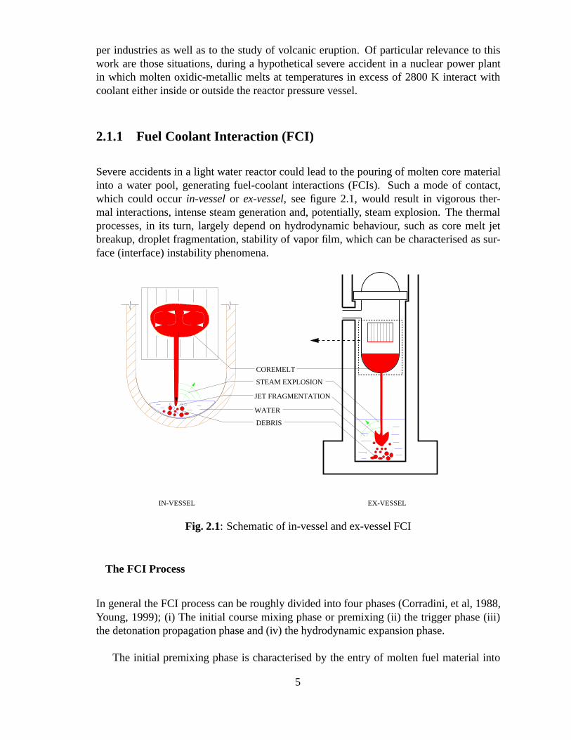
Severe accidents in a light water reactor could lead to the pouring of molten core materialinto a water pool, generating fuel-coolant interactions (FCIs). Such a mode of contact,which could occur in-vessel or ex-vessel, see figure 2.1, would result in vigorous ther-mal interactions, intense steam generation and, potentially, steam explosion. The thermalprocesses, in its turn, largely depend on hydrodynamic behaviour, such as core melt jetbreakup, droplet fragmentation, stability of vapor film, which can be characterised as sur-face (interface) instability phenomena.
EX-VESSEL
DEBRIS
WATER
JET FRAGMENTATION
STEAM EXPLOSION
COREMELT
IN-VESSEL
Fig. 2.1: Schematic of in-vessel and ex-vessel FCI
The FCI Process
In general the FCI process can be roughly divided into four phases (Corradini, et al, 1988,Young, 1999); (i) The initial course mixing phase or premixing (ii) the trigger phase (iii)the detonation propagation phase and (iv) the hydrodynamic expansion phase.
The initial premixing phase is characterised by the entry of molten fuel material into
5
the water coolant. The fuel enters in the form of jets or drops which interact with thewater, with accompanying vapor generation, mixing of melt material, vapor and water.The melt jets and drops break up into smaller diameter drops. The breakup process ismainly governed by two types of hydrodynamic instabilities, namely; the Rayleigh-Taylorand Kelvin-Helmholtz instabilities. The breakup process is either driven by acceleration orvelocity difference between the molten fuel and the coolant surrounding. The vapor filmaround the molten fuel insulates it from the water. This lowers the cooling rate of the fuelparticles.
The process enters the triggering phase when the vapor film, around the molten fuel,collapses due to local perturbation. The collapse of the vapor film allows the water to comein near contact or in contact with the molten fuel which enhances the heat transfer betweenthe molten fuel and the surrounding water and increases the velocity in the vicinity of thetrigger. If the triggering event is energetic enough the MFCI process enters the next phase,the detonation propagation phase.
The detonation propagation phase is characterised by the sharp micro-interaction zonewhich propagate through the entire mixing zone. In the micro interaction zone the moltenfuel is fragmented to small particles, resulting in rapid increase in interfacial area of the fueland coolant. This increases the release of heat to the surrounding water, the intensive steamgeneration then may generate the shock waves. The same instabilities as in the premixingphase could be responsible for the rapid fine fragmentation of the molten fuel during thedetonation propagation phase.
In the expansion phase the thermal energy is converted into mechanical energy whichacts on the surroundings.
The in-vessel and ex-vessel scenarios
The in-vessel stage of FCI is of great importance from two points of view. First, the en-ergetics and destructive forces of a potential in vessel steam explosion (� - mode) couldpresent a potential threat to the vessel and the surrounding containment integrity. Recentstudies, see e.g. Theofanous and Yuen (1995), Speis and Basu (1991) and Turland et.al.(1993) on in-vessel FCI have led to the conclusion that vessel failure due to potential steamexplosion is highly unlikely or may be impossible. This conclusion has reduced the signif-icance of the in-vessel steam explosion. Secondly, fragmentation behaviour and interfacearea evolution of the fragmented core melt determines the configuration of the debris bedformed in the lower plenum of the reactor pressure vessel. Furthermore, if the moltencorium jet breaks up during its interaction with the water, it does not impinge on the vesselwall and hence reduce the potential danger to the vessel wall.
The ex-vessel scenario is important for plants in which water may accumulate in thecontainment below the vessel. Such a hypothetical situation may arise in the ABB boilingwater reactor (BWR) plants which are located in Sweden and Finland. These plants employ
6
a severe accident management procedure, in which a deep, highly-subcooled, water poolis established under the vessel, as soon as it becomes clear that the water level in the coremay fall below the top of the fuel. The motivation for this strategy is the engineeringjudgement that the core melt jet will break up during its passage through the water and thatthe debris bed formed can be cooled permanently within the water pool. The success ofthis procedure is predicated upon the engineering judgement that a large steam explosion,which could threaten the containment integrity during the melt-water interaction, will notoccur.
2.2 Molten fuel-coolant premixing
2.2.1 Status of current research and recent results
Although remarkable progress in the description of the pre-mixing and expansion phases ofthe steam explosion has been achieved in recent years, the initial phase of the FCI processis not yet well understood. This includes jet break up, droplet formation and subsequentfragmentation. Several large-scale experimental programs and analyses efforts are under-way to determine physical mechanisms associated with FCIs and to provide models andmethods, which could be used to predict the consequences of FCIs in reactor accident situ-ations; see e.g. recent reviews by Turland and Dobson (1996), Berthoud (1996), Magallonet al. (1995a). In the experimental investigation, both prototypic and simulant materialswere employed.
The objective of the experiments with prototypic material was to characterise the breakupand mixing of corium melt jets falling into water. The role of the melt physical propertiesin these processes were assessed and the adequacy of the premixing models to describe thebehaviour of prototypical corium at different scales were verified. The experiments wereconducted at JRC-lspra in the KROTOS and FARO facilities, by using up to 175 kg ofmolten UOz-Zr02 at 3000 K.
The objective of the experiments with simulant materials was to fully understand therole of the melt physical properties in the FCI processes and their influence over a largerrange of values to determine the dominant factors. At FZK, the experiments were con-ducted by using up to 60 kg of molten alumina at 2600 K in the PREMIX facility, andat RIT with tests involving up to 30 kg of different molten binary oxides (CaO � B203,MnOz-TiOz andW3�CaO) at various temperatures up to 1600 K in the MIRA facility. TheMIXA (Corradini, et al., 1988), MAGICO (Angelini, et al., 1995), BILLEAU (Berthoud, etal., 1996a), and QUEOS (Meyer, 1996) tests were conducted, using jet-like configurationsof hot spheres, in order to obtain data for validation of the pre-mixing models and codessee e.g. Theofanous et al. (1996) and Berthoud (1996). In JEFRI tests (IKE, Stuttgart,Germany) (Burger, 1995) the low temperature experiments were performed using Wood’smetal as jet simulant fluid and freon R113 as coolant.
7
The KROTOS tests of JRC-Ispra specifically aimed at understanding whether steam ex-plosions could be triggered with UO2 � ZrO2 melt pouring into water and what were theenergetics involved. Melt jets had an initial diameter of 30 mm for a melt mass around 4 kg.The water was contained in a test section of diameter 200 mm and had a depth of the orderof 1 m. An external trigger could be applied at the bottom of the water column. The dy-namic pressurisation of the test section during the propagation phase and the pressurisationof the test vessel during the expansion phase were measured. Visual observations of meltinjection and fall through the water were performed with different video cameras, up to1000 f/s. The four tests performed showed that a coherent melt jet penetrated deep into thewater as opposed to alumina melt jets, which typically experience complete break-up in theuppermost region of the water column. No spontaneous explosion occurred in the coriumtests, but it has been possible to trigger energetic events by reducing the void fraction in thepre-mixing phase by increasing the system pressure. However, the work outcome of theseinteractions was low (0.15% of the melt thermal energy maximum).
The FARO tests of JRC-Ispra provided the project with data on quenching large massesof corium melt in 3-D configurations. No external trigger was applied. The water depthwas typically 1.5 m and the water pool had a diameter of 0.71 m. In addition to the jetbreakup and mixing aspects, the tests in FARO provided global data on quenching anddebris bed characteristics. The tests were performed in the FAT vessel provided with viewports for visualisations, which allowed to characterise the melt entry conditions. Two testswere performed in saturated (in-vessel typical, L-28) and subcooled (ex-vessel typical, L-31) water. No spontaneous steam explosion occurred. In tests L-28 performed at 0.5 MPa,a long (6 s) quasi-steady pour was obtained by using a jet diameter of 5 cm melt jet anda melt mass of 175 kg. The test demonstrated an important feature never yet obtainedexperimentally, i.e., that the quenching rate rapidly stabilised to a constant value (-30 MW)for all the duration of the jet. In the conditions of the test this value corresponds to aboutI MJ/kg of melt, i.e. 2/3 of the energy content of the melt. Subcooled water test L-31was performed at 0.2 MPa and a reduced quantity of melt (92 kg) for safety reasons. Nofundamental differences in quenching were observed with respect to saturated water tests.The particle size of the debris was of the same order as that for the particulate debris foundin saturated water tests. No cake was present in test L-31. However, a preliminary test insubcooled conditions (L-29) revealed little fragmentation during melt fall through water,inducing the melt to collect largely unquenched on the bottom. The reasons for such anunexpected behaviour were attributed to the initial conditions and raised the question of theconsequences on resolving debris coolability issues.
In the PREMIX tests of FZK the alumina melt was poured into about 1.3-m-depth sat-urated and subcooled water at velocity up to 4.3 m/s from nozzles of diameter rangingbetween 48 and 60 mm and at system pressures from 0.1 to 0.5 MPa. Tests performedat different pressures and similar other conditions showed that increasing the system pres-sure keeps the steam mass generation rate quasi unchanged, produces larger fragments andresults in a narrower and less violent mixing zone. A narrower mixing zone was also ev-idenced in subcooled water with respect to saturated water. In tests performed in sameconditions but different melt masses, the test performed with 60 kg of melt (P1, long pour)produced much more steam than what could have been expected from the test performed
8
with 23 kg of melt (P3), A cake formed in P1 (half cake, half loose debris). No steamexplosion occurred in any of the tests and negligible amount of hydrogen was produced.
The result obtained from the MIRA experiments with simulant materials at RIT is thatthe melt jet fragmentation may be classified into two regimes of either fragmentation-controlled or solidification-controlled. The delineation between these two regimes was re-alised from the characterisation of the solidified debris. The coolant temperature was foundto have a primary role in these fragmentation regimes. At low subcooling (solidification-controlled regime) the fragments are relatively large and irregular compared to smallerparticles produced at high subcooling (fragmentation-controlled regime). It was also foundthat as the melt density increases smaller particles are produced during the jet breakup.Within the range of melt temperature tested, the melt superheat was found to have little ef-fect on the debris particle size distribution produced during the melt jet fragmentation. Theimpingement velocity of the jet was found to have significant impact on the fragmentationprocess. At lower jet velocity the larger size particles are formed and they are found toagglomerate and form a cake of low porosity as observed in the FARO tests. When the jetvelocity is high, more complete fragmentation is obtained.
For BWR plants, there exists a large amount of metal melt which may be dischargedto the drywell water pool in form of jets. It was also postulated that the prototypic meltwith a metallic component may be more conducive to fragmentation. On the other hand,it has also been postulated that hydrogen may play a role in suppressing augmentation.The experimental program at the Argonne National Laboratory has focused on whetherchemical augmentation of the energetics can occur in Zr-water and Zr-ZrO2-water steamexplosion. Melt quantities up to 1 kg of both Zr-water and Zr-ZrO2-water were droppedinto a column of subcooled water. Explosions took place only when an external trigger wasused. In the triggered tests, the extent of oxidation of zirconium melt was very extensive.However, the measured explosion energetics were much less than the potential chemicalenergy available from the oxidation reaction. This indicates limited chemical augmentationduring the explosion time scale.
2.2.2 Inter-relations and uncertainties of molten fuel-coolant premix-ing
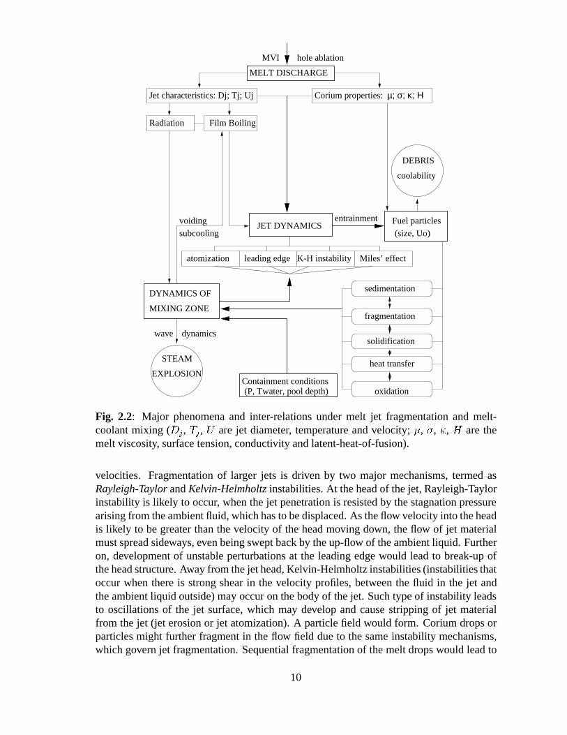
A large number of heat and mass transfer phenomena occur during MFCIs. Phenomeno-logical uncertainties associated with melt-water interactions are contributed by the complexnature of, and feedbacks between, melt-water hydrodynamic and thermal interactions. Theschematic representation of these interactions, and feedbacks is shown in Fig.2.2.
In the premixing phase, the fragmentation behaviour of the core melt is governed byvarious instability mechanisms, developed as a result of (liquid-liquid) contact and relativemovement between corium and coolant. Fragmentation of narrow melt jets, for instance,is governed by the capillary instability, brought about by surface tension effects at low
9
(P, Twater, pool depth)
MELT DISCHARGE
coolability
DEBRIS
JET DYNAMICS(size, Uo)
Fuel particles
Jet characteristics: Dj; Tj; Uj Corium properties: µ; σ; κ; Η
Radiation Film Boiling
EXPLOSION
STEAM
dynamicswave
DYNAMICS OF
MIXING ZONE
hole ablationMVI
voidingsubcooling
atomization leading edge Miles’ effect
sedimentation
fragmentation
solidification
heat transfer
oxidation
entrainment
K-H instability
Containment conditions
Fig. 2.2: Major phenomena and inter-relations under melt jet fragmentation and melt-coolant mixing (Dj, Tj , U are jet diameter, temperature and velocity; �, �, �, H are themelt viscosity, surface tension, conductivity and latent-heat-of-fusion).
velocities. Fragmentation of larger jets is driven by two major mechanisms, termed asRayleigh-Taylor and Kelvin-Helmholtz instabilities. At the head of the jet, Rayleigh-Taylorinstability is likely to occur, when the jet penetration is resisted by the stagnation pressurearising from the ambient fluid, which has to be displaced. As the flow velocity into the headis likely to be greater than the velocity of the head moving down, the flow of jet materialmust spread sideways, even being swept back by the up-flow of the ambient liquid. Furtheron, development of unstable perturbations at the leading edge would lead to break-up ofthe head structure. Away from the jet head, Kelvin-Helmholtz instabilities (instabilities thatoccur when there is strong shear in the velocity profiles, between the fluid in the jet andthe ambient liquid outside) may occur on the body of the jet. Such type of instability leadsto oscillations of the jet surface, which may develop and cause stripping of jet materialfrom the jet (jet erosion or jet atomization). A particle field would form. Corium drops orparticles might further fragment in the flow field due to the same instability mechanisms,which govern jet fragmentation. Sequential fragmentation of the melt drops would lead to
10
the formation of very fine debris structure.
Thermal interactions between core melt and water are governed by the heat transferfrom the melt to water by film boiling and/or heat radiation. Under the thermal exchangethe melt would cool down and solidify, while the water would heat up and vaporise. Thechange of melt properties during its solidification and the formation of a two-phase (water-steam) zone around the melt field would provide significant feedbacks to further melt frag-mentation and mixing.
Parameters of importance are also specified in Fig.2.2. Complex feedbacks and lackof appropriate database at high temperatures are the major obstacles to development ofmechanistic models of MFCIs.
The key scenario uncertainties for ex-vessel melt-coolant premixing can be categorisedinto two groups.
1. Water pool conditions, which can vary depending on the water available, the geomet-rical characteristics of the drywell, and the accident management actions undertaken.
2. Melt conditions. The mode and length scale (diameter) of melt discharge, the meltsuperheat and composition, the number of simultaneous jets, etc. largely depend onin-vessel melt progression scenarios.
2.2.3 Self-limiting mechanisms in melt-water premixing
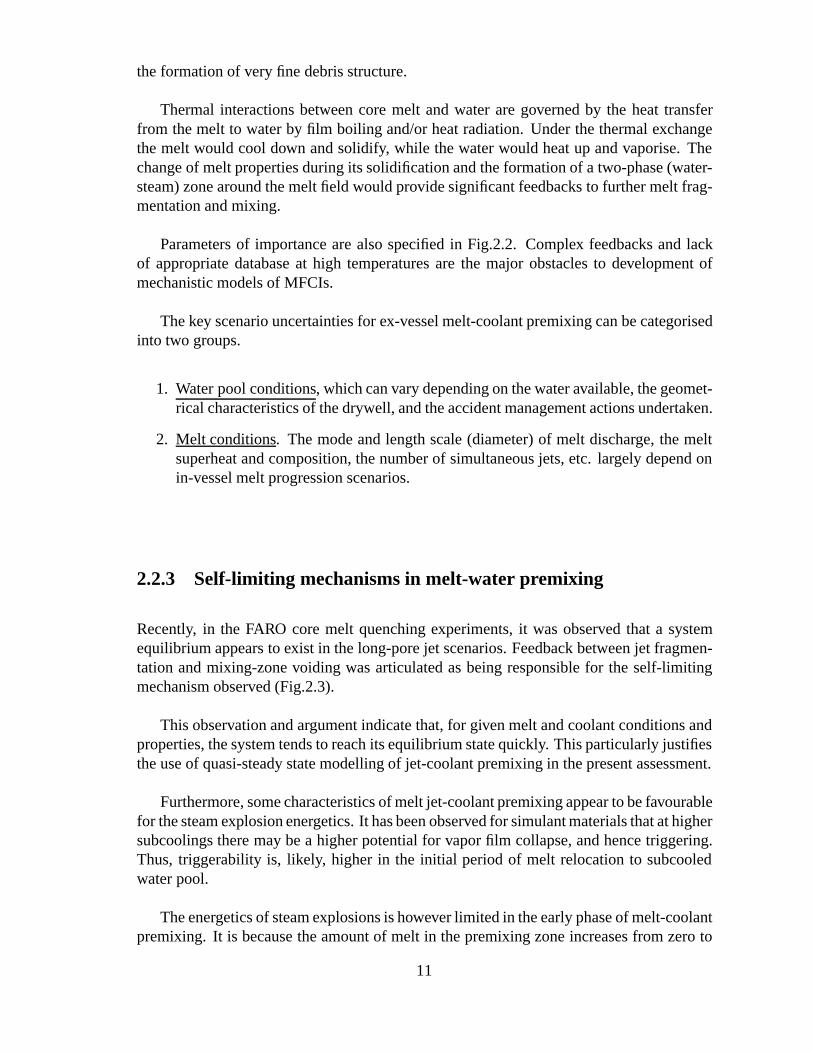
Recently, in the FARO core melt quenching experiments, it was observed that a systemequilibrium appears to exist in the long-pore jet scenarios. Feedback between jet fragmen-tation and mixing-zone voiding was articulated as being responsible for the self-limitingmechanism observed (Fig.2.3).
This observation and argument indicate that, for given melt and coolant conditions andproperties, the system tends to reach its equilibrium state quickly. This particularly justifiesthe use of quasi-steady state modelling of jet-coolant premixing in the present assessment.
Furthermore, some characteristics of melt jet-coolant premixing appear to be favourablefor the steam explosion energetics. It has been observed for simulant materials that at highersubcoolings there may be a higher potential for vapor film collapse, and hence triggering.Thus, triggerability is, likely, higher in the initial period of melt relocation to subcooledwater pool.
The energetics of steam explosions is however limited in the early phase of melt-coolantpremixing. It is because the amount of melt in the premixing zone increases from zero to
11
Existence of System Equilibrium State (SES)
System Equilibrium Analysisfor MFCI with long-pour jet
Evolution of Heat Transfer
(Melt-Coolant) Interfacial Area
Energy Input intoCoolant Media
Coolant Voidingwith voiding increase)
Steam Production &
Negative feedback
Drop Fragmentation
(drop size decreases
Debris Volume Fraction
(debris fraction decreases
with voiding increase)
Method for Determining Parameters of the SES
Fig. 2.3: Feedback relations and system equilibrium.
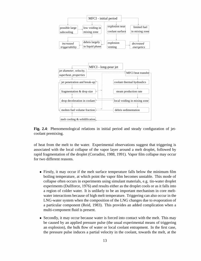
establish a quasi steady-state value. Concurrently, the more the melt mass in the premixingzone, the less the coolant subcooling in the melt-water interaction zone. Therefore, it isexpected that the increased triggerability in the initial mixing period is coupled with thedecreased energetics due to the melt mass limitation discussed above (see Fig.2.4).
2.3 Molten fuel-coolant triggering
2.3.1 Status of current research and recent results
Triggering is a complex process which is poorly understand. In any experiment, it is obvi-ous whether a trigger which is sufficient to cause propagation has occurred or not. But if anexplosion does not occur, it is not possible to conclude that a trigger did not occur; it maybe that the mixture conditions were not ”right” and a propagating wave did not develop.
Triggering is the event which initiates the rapid local heat transfer and pressure risewhich is necessary if a propagating wave is to develop and to lead to the rapid transfer
12
superheat, properties
coolant thermal hydraulicsjet penetration and break-up
fragmentation & drop size
drop deceleration in coolant
molten fuel volume fraction
local voiding in mixing zone
steam production rate
MFCI heat transfer
debris sedimentation
melt cooling & solidification
MFCI - long-pour jet
MFCI - initial period
possible large
subcooling
low voiding inmixing zone
debris largely
in liquid phasetriggerabilityincreased
limited fuel
in mixing zone
explosion near
coolant surface
explosionventing energetics
decreased
jet diameter, velocity,
Fig. 2.4: Phenomenological relations in initial period and steady configuration of jet-coolant premixing.
of heat from the melt to the water. Experimental observations suggest that triggering isassociated with the local collapse of the vapor layer around a melt droplet, followed byrapid fragmentation of the droplet (Corradini, 1988, 1991). Vapor film collapse may occurfor two different reasons.
� Firstly, it may occur if the melt surface temperature falls below the minimum filmboiling temperature, at which point the vapor film becomes unstable. This mode ofcollapse often occurs in experiments using simulant materials, e.g. tin-water dropletexperiments (Dullforce, 1976) and results either as the droplet cools or as it falls intoa region of colder water. It is unlikely to be an important mechanism in core melt-water interactions because of high melt temperature. Triggering can also occur in theLNG-water system when the composition of the LNG changes due to evaporation ofa particular component (Reid, 1983). This provides an added complication when amulti-component fluid is present.
� Secondly, it may occur because water is forced into contact with the melt. This maybe caused by an applied pressure pulse (the usual experimental means of triggeringan explosion), the bulk flow of water or local coolant entrapment. In the first case,the pressure pulse induces a partial velocity in the coolant, towards the melt, at the
13
liquid-vapour interface. If this motion is sufficient to drive the water into contactwith the melt, triggering occurs. In the second case, the bulk flow of water pasta droplet (without a pressure wave present) causes the vapor layer to be convectedaway from the melt, causing film collapse. In the third case, water is entrapped withinthe melt, and is superheated until its temperature rises to the homogeneous nucleationtemperature, at which point it flashes into steam throwing the melt surrounding it intocontact with water, and triggering occurs.
Explosions which result from a known trigger are usually referred to as triggered ex-plosions, and those occurring because of some uncontrolled event are usually referred toas spontaneous explosions. If the trigger is provided by some artificial means, such asa detonator, the explosion is said to be externally triggered. The triggering is a compli-cated phenomenon, which is difficult to model and quantify. In the following sections, allavailable experimental data and analytical modelling work are summarized.
2.3.2 Triggering experiments
Experiments using a solid hot surface
In order to study the vapor film collapse process, some workers have used a solid heater.This has the advantages that the geometry is well-defined, and it is possible to control andmeasure the surface temperature of the ”melt”, and explosions can not occur. Thus thiskind of experiments decouple the processed of vapor film collapse and droplet fragmenta-tion. Early experiments of a qualitative nature are described by Naylor (1985). Inoue andBankoff (1981), Inoue (1982) investigated the triggered collapse of film boiling of differ-ent liquids (Freon-113, ethanol and water). It was found that the vapor film collapse wasobserved when the pressure rise time is very small.
Naylor (1985) studied untriggered and triggered film boiling collapse on the surface ofa brass rod with a hemispherical end immersed in a pool of water. Metal temperatures up to770K and water subcoolings at ambient pressure ranging from 0 to 80K were considered.They were instrumented using a variety of photographic means (including an IMACONcamera), a contact resistance device which allowed the fraction of the film area which hadcollapsed to be estimated, thermocouples to determine the metal and water temperaturesand pressure transducers. He observed that the film could be collapsed by either a pressurepulse or by the bulk flow of liquid. The collapse of the film was often accompanied by aloud noise which resembled a ”rifle shot”. Observations suggested that collapse occurredwhen the average film thickness was less than the sum of the surface roughness plus theamplitudes of interfacial waves on the liquid-vapor interface.
14
Single droplet tests
The behavior of single droplets of melt released into a tank of water has been studied bynumerous workers. Experiments using tin (Dullforce, 1976), iron oxide (Nelson, 1982),lead (Frolich, 1976), copper (Zyszkowski, 1976) and a host of other materials have allyielded information on the vapor film collapse and subsequent fragmentation process. Therole of the interface temperature in determining the fragmentation behavior has been ex-amined for a variety of molten metals by Watts et al. (1993). This type of experimentyields information not only on the vapor film collapse process but also on the violence ofthe fragmentation event which follows.
Dullforce et al. (1976) developed the concept of a temperature interaction zone (TIZ).They performed hundreds of experiments in which molten tin droplets were released intowater, and determined the region in melt temperature-water temperature space in whichspontaneous explosions occurred. The region in which they occurred was termed the TIZ.The boundary of the TIZ depends on (1) the chosen melt, (2) the melt mass, (3) the timeavailable for film collapse to occur. In addition, it is possible to trigger interactions for thesituation in which a spontaneous interaction does not occur. Various theories have been ad-vanced to explain the boundaries of this region, usually based on the need for the interfacecontact temperature to be above the spontaneous nucleation temperature (see Corradini etal. (1988) for details).
Corradini (1981) has analysed the data from over 300 single droplet experiments per-formed by Nelson at Sandia National Laboratories. The experiments involved the releaseof small droplets of various melts (stainless steel, metallic corium and oxix corium) intowater. Two different triggers were used. The first was an exploding bridgewire, giving apeak pressure of 1 MPa at a distance of 40 mm and a rise time of � 1�s. The second wasa detonator, giving a pressure of 10MPa at a distance of 40 mm and a rise time of � 20�s.Following conclusions were made:
� Certain melt compositions did not lead to explosions and this could be explained bythe presence of non-condensible gases, particularly hydrogen in the case of metallicmelts.
� Explosions were suppressed at high ambient pressures because of the increased vaporfilm stability.
� Increasing the trigger magnitude can result in an explosion for a case where an ex-plosion did not occur for a weaker trigger.
Experiments performed at Sandia National Laboratories have identified a trigger thresh-old for efficient fragmentation of a single droplet melt (Beck, 1991, Berman, 1989). A threeorder of magnitude increase in the volume of the vapor bubble formed following the frag-mentation of a single melt droplet was observed when the trigger strength, defined as theproduct of the trigger pressure and impulse, exceeded a critical value. Berman and Beck
15
(1989) have developed an empirical parameterization of trigger strength, based on an anal-ogy with explosive welding. and believe that the trigger strength can be characterized bythe product of the trigger pressure and impulse.
These experiments have lead to the development of a vast number of models of frag-mentation (Corradini, 1988). However, these mechanisms are applicable to isolated dropletswhich either spontaneously explode or are subjected to rather short duration pressure pulse.Thus the mechanism identified in this kind of experiments may not necessarily apply duringthe propagation stage of an explosion. Such concerns have motivated Theofanous and co-workers to investigate the fragmentation of droplets following sustained pressure loadings(Yuen, 1992).
Triggering in integral experiments
In this section the triggering behavior observed in medium-scale experiments are summa-rized.
The experimental programmes performed at AEA Winfrith, Argonne National Labo-ratory, Sandia National Laboratory, JRC Ispra and JAERI all provide useful informationon triggering. The difficulty with extracting data from such tests is that the occurrence ornot of an explosion is rather uncontrolled, unless the system (by which it is meant the meltcomposition, melt temperature, water subcooling, ambient pressure and contact mode) isin a certain region of parameter space, which will have been determined from previousexperiments of a similar kind.
The following conclusions can be drawn after the examination of the data from theseintegral experiments (Fletcher, 1995):
� Experimental data show very clearly the random nature of the triggering process.
� Explosions can be triggered as the melt enters the water pool, as it is falling, uponbase contact or after melt has collected on the base of the mixing vessel. Explosionsfrequently occur without an applied external trigger.
� The spontaneous explosions which occur when melt contacts the water can be sup-pressed by a small increase in the ambient pressure (as little as 0.5 - 1.0 MPa is oftensufficient). Data from the Sandia (FITS) and Winfrith (SUW) support this view.
� There is no clear evidence for a triggered explosion occurring at pressures aboveabout 3 MPa. An explosion was triggered at 5.8 MPa in the (HPTR) experimentsperformed at Winfrith but this involved the injection of a slug of cold water intothe mixture. An explosion was triggered at a pressure of 1.0 MPa in the (SUW)experiments when the end-cap from the charge container hit the base of the mixingvessel.
16
� Explosions are much more likely to occur in subcooled conditions compared withsaturated conditions. This conclusion is supported by the results from the experi-mental series performed at Sandia (e.g. CM, OM, FITS), Winfrith (WUMT), Ispra(KROTOS) and JAERI.
� There is considerable evidence that if the melt is pre-dispersed it is much less likelythat an explosion will trigger. Again results from experiments performed at Sandia(Open Geometry Tests), Winfrith (MIXA) and JAERI support this statement.
� There is evidence that if the melt has a low superheat, partial solidification during themelt/water interaction can inhibit triggering.
2.3.3 Analytical work on triggering
Most modelling attempts have followed a very similar approach. A one-dimensional modelconsisting of a melt layer, a vapor layer and a liquid slug, is usually assumed. The idealisedgeometry represents a section of the vapor film surrounding a melt droplet. Steady-statefilm boiling is assumed to be established prior to the arrival of a pressure wave at theliquid-vapor interface. Conservation equations for mass, momentum and energy are thenused to model that transient evolution of the system. The main difference between thevarious models is in the level of complexity of the equation system used and in the physicalprocesses modelled.
The earliest model appears to be that of Drumheller (1979), who considered the sym-metric collapse of film boiling around a sphere. The liquid was assumed to be incompress-ible and energy considerations were used to derive an equation similar to Rayleigh’s classi-cal bubble collapse equation, but with phase change terms. The assumption of sphericallysymmetric collapse would appear to be questionable because of the finite time required fora pressure pulse to pass the sphere. No comparisons with experimental data were madeusing this model.
The first detailed model to be developed and compared with experiment was that ofInoue et al. (1981b). In their model, a full non-equilibrium kinetic theory treatment ofevaporation and condensation was used at the vapor-liquid interface and a Knudsen layerwas modelled at the melt-vapor interface. The heat conduction equation was solved in themoving liquid slug by assuming a temperature profile which was a quadratic function of thedistance from the vapor-liquid interface. A newtonian model of the slug dynamics was usedto determine the motion of the liquid. No vapor flow out of the film was modelled. Theresults of the calculations for a liquid of Freon-113 highlighted the importance of choosingthe evaporation-condensation accommodation coefficient correctly.
A simplified model was also developed by the above workers in which the heat storagein the vapor film was neglected and a heat balance was applied at the liquid-vapor interfaceto determine the condensation or evaporation rate, with the liquid-vapor interface temper-
17
ature set to the local saturation temperature. This resulted in a much simpler set of modelequations. The model was found to give bether agreement with measured heat flux datafrom Freon-113 vapor film collapse experiments. For any applied pressure pulse, the cal-culated response of the system was either total collapse of the film or oscillation of the filmthickness, with the pressure in the film rising sufficiently as collapse started to occur that itpushed the slug away.
Knowles (1985) developed a one-dimensional model based on similar assumptions tothose of Inoue et al. (1981b). However, his model employed a more rigorous treatmentfor the slug dynamics and heat transfer into the vapor layer. The detailed behavior ofthe incident pressure pulse could be modelled. Equations from kinetic theory were usedto simulate evaporation/condensation processes, with the kinetic theory equations beingmodified to allow for the net velocity of the interface. The analytical results showed thatif the particle velocity of the liquid at the slug-vapor interface multiplied by the durationof the pressure pulse is greater than the thickness of the vapor film, collapse will occur.The simulation also showed that at higher melt temperatures, stability was maintained byevaporation from the advancing slug. Since the vapor flux from the slug would mix up anypermanent gas present, it would not produce a mass transfer barrier.
Although a number of models have been developed, because of the assumptions em-ployed in the models, they are difficult to apply in any real situation because of uncertaintiesin the initial vapor film thickness and the geometry, and the poor knowledge of the triggercharacteristics. The evidence from model predictions is that triggering becomes more dif-ficult at higher pressure and for higher melt temperature. As the pressure increases, thevapor mass and the energy densities increase and the latent heat of vaporation decreases sothat it becomes more difficult to compress the film, more difficult to condense the vaporand easier to evaporate the leading edge of the water slug.
2.3.4 Conclusions
Base on the review by Fletcher (1995), the following conclusions and judgments can bemade:
� Triggering probability: The available data and modeling do not justify making strongclaims using triggering arguments in steam explosion assessments. They do, how-ever, allow modest claims for the lack of an effective trigger and allow the relativelikelihood of triggering during the various stages of the melt-water interaction to beestimated. Any estimates of triggering probability are subjective, but there is a rela-tively large pool of data from experiments of the order of 10 kg of prototypical melton which to base this judgment.
� Influence of pressure and subcooling: Data available do not support the hypothesesthat early triggering is virtually certain and that triggering at high pressure is impos-sible. The available data do, however, suggest that triggering becomes more difficult
18
with increased pressure. Experimental results show that even a small increase inpressure from 0.1 to 0.5 MPa can inhibit spontaneous triggering. If melt-water mix-ing occurs in subcooled water, as is likely in ex-vessel melt-water interactions, thelikelihood of triggering is increased significantly.
� Models and mechanisms: No validated triggering model exists. Experimental ob-servations suggest that triggering is associated with the local collapse of the vaporlayer around a melt droplet followed by rapid fragmentation of the droplet. Vaporfilm collapse may occur for a number of reasons: interface contact temperature fallsbelow minimum film boiling temperature (unlikely in core melt-water interactions);water is forced into contact with melt by applied pressure pulse (used often in exper-iments), by forced flow of water collapsing the vapor film (low melt temperature orhigh water subcooling) or by local coolant entrapment (water entrapped within themelt or against the pool base).
It should be noted, from the review of Fletcher, that the ex-vessel conditions in theSwedish BWRs could lead to triggering near the pool surface. In fact, this high melt ve-locity and water subcooling-induced triggering sensitivity has already been suggested byTheofanous (1994). He also acknowledged the fact that only in special cases can one pre-dict the occurrence of triggering, and it is thus reasonable to consider a spectrum of timingsand positions.
2.4 Results from steam explosion experiments with differ-ent melt materials
In this section, the results from steam explosion experiments with different melt materialsare briefly summarized.
Bird and Millington (1979) and Bird (1984) performed two series of experiments toinvestigate interactions between thermite-generated uranium-dioxide-molybdenum meltswith water. Berman et al (1984) performed a similar series of experiments at Sandia withcorium melt using a thermitic reaction in which a substantial fraction of stainless steel waspresent. In all of these experiments, both spontaneous and triggered steam explosions wereobserved.
Steam explosion experiments were performed in KROTOS facility at Ispra (Italy). Boththermite alumina Al2O3 melt and core melt UO2-ZrO2 were employed (Huhtiniemi andMagallon, 1997). Spontaneous and triggered steam explosions were observed in most of theexperiments using alumina melt. No propagating energetic event has been observed, so far,in KROTOS experiments employing binary oxidic core melt, with and without triggering.FARO experiments employing up to 200 kg of binary oxidic core melt have been performedat Ispra. Although the purpose of the FARO experimental series is to study melt quenchingphenomena, no steam explosion has occurred, so far, even for such a large pre-mixture.
19
ZREX experiments, performed in Argonne National Laboratory and employing almostpure metallic zirconium melt, consistently produced steam explosions. Presence of metalmelt appears to create favorable conditions for steam explosion. Chemical augmentationof the explosion energetics due to metal oxidation was found to be quite small (Cho et al.,1997).
PREMIX experiments performed in Karlsruhe (Kaiser et al., 1997) employed aluminamelts generated by thermitic reaction. The melt was however not pure alumina, but con-tained variable fractions of iron oxide, Fe2O3, and in some cases, other oxides like CaO andSiO2. No triggering was applied. From 13 experiments performed, only one mild explosionwas observed, when melt was delivered to water pool as multiple (three) jets.
It appears that while metal melt and alumina melt are vulnerable to explosions, i.e.have high explosivity, binary and multi-component oxidic melts have low explosivity. Re-sults of the KROTOS experiments with corium compared to those with alumina in whichno explosion occurred showed that corium melt fragments into much finer particles thandoes the alumina melt. KROTOS alumina experiments, without explosion, generate large-diameter particle (8-10 mm). From PREMIX experiments, the size of debris particles waseven larger (17-20 mm). This appears to be a direct result of the much higher density ofthe corium melt (' 8000 kg/m3) versus that of the alumina melt (' 2700 kg/m3).
2.5 Computational investigation of steam explosion
In this section, the representative computer codes for steam explosion are introduced, theirperformances of steam explosion estimation are also presented.
2.5.1 PM-ALPHA and ESPROSE.m codes
The progression of a steam explosion scenario has been modeled in two phases, namely thepremixing and the propagation phases. The PM-ALPHA code model the first phase, whilethe ESPROSE.m code simulates the second phase. Both codes employ advanced multi-fluidmulti-dimensional models, computational techniques and physical understandings aboutthe steam explosion phenomenology.
The PM-ALPHA code employs a multifluid approach to describe the system consistingof melt and coolant (water and vapor). The emphasis of the code is placed on addressingthe multifield behavior and interactions. A very (cautious) phenomenological approachwas developed and applied to treat melt breakup and fragmentation, based on the conceptof interfacial area evolution.
The multifield treatment in the PM-ALPHA code consists of the field conservation
20
equations in a 2D formulation and the constitutive laws that describe interfacial transfers.The constitutive laws allow for some inhomogeneities as distinguished by applicable flowregimes. In particular, a flow regime map was employed to describe the changes in interfa-cial interactions for different vapor contents.
In the PM-ALPHA code, only two melt length scales are recognized: one fine enoughto yield fragments that can be captured by the liquid field, and one large enough to continuewith the continuous fuel field. The change in length scale, leading to the formation of ”fine”and ”large” fragments, is caused by processes named as ”fragmentation” and ”breakup”respectively.
The propagation phase of steam explosion is tracked by the ESPROSE.m code. Thecode can follow the propagation of a steam explosion in a given premixture, but not con-sidering any physics of triggering. The major feature of the ESPROSE.m code is its ”mi-crointeractions” concept, which is claimed to be able to provide correct descriptions of meltfragmentation, mixing of the resulting debris with some of the surrounding coolant, and theassociated heat transfer, thermal expansion, and even phase change. In realization of thisconcept, a special field, generically called ”m-field”, which is made up of coolant and meltdebris, is employed. Intense thermal interactions are assumed to occur in the m-fluid. It isalso assumed that heat transfer from the debris to the coolant in the m-fluid is instantaneousand that the coolant is in local thermodynamic equilibrium.
In difference to the other steam explosion codes, the ESPROSE.m code is based ona 2D formulation, which makes the code suitable to describe the propagation of shockwaves in complex geometries, while accounting for the multidimensional reflections on theboundaries.
Both PM-ALPHA and ESPROSE.m codes were validated against a selected set of avail-able experimental data. The PM-ALPHA code, for instance, was claimed to provide excel-lent prediction for the FARO and MAGICO-2000 experiments, while good comparisons ofthe ESPROSE.m predictions with the SIGMA-2000 and KROTOS data were also reported.
Recent improvements of the codes and potential impact
Recently, both the PM-ALPHA and the ESPROSE.m codes have been extented to 3D for-mulations, which, however, have a small effect on the PM-ALPHA premixing prediction.The PM-ALPHA code was significantly improved with a new Lagrangian treatment forthe melt phase, which helps to mitigate numerical diffusion, which can quickly spoil thesharpness of the melt front during its progression into coolant. Moreover, the premixingcode is also equipped with a shell-freezing model for the melt and a model of the fullturbulence-controlled heat transfer on the liquid side of the interfaces. Some improvementof the heat radiation transport model was also reported. A better description of melt-coolantheat transfer and melt solidification would certainly affect the steam explosion predictionresults.
21
The new versions of the PM-ALPHA and the ESPROSE.m codes have been testedagainst the QUEOS, FARO, MAGICO (for PM-ALPHA) and SIGMA (for ESPROSE.m)experimental data.
2.5.2 MC3D code
MC3D developed by CEA-Grenoble in France is a three-dimensional, multi-component,semi-implicit, Eulerian computer code. Its purpose is to model fuel-coolant interactionfrom the beginning (the premixing of fuel drops with water) to the end (the fragmentationinto small fuel droplets and the escalation and propagation of the steam explosion). MC3Dpossesses a common kernel (including solvers, input...) and several modules written tomodel particular problems.
The explosion module of MC3D is dedicated to model the fine fragmentation phaseand the explosion. The code models four fields: liquid coolant, vapor, fuel drops andfuel fragments. The code distinguishes the small fuel fragments from the large fuel dropsbecause the heat transfer process with water is different for both kinds of fuel. For eachfield, the code solves a mass equation, a momentum equation for each of the three directionsand an energy equation. An additional volume conservation completes the equation set.Pressure can be either subcritical or supercritical.
The mass equations account for two fuel fragmentation mechanisms:
� the thermal fragmentation is caused by the destabilization of the vapor film surround-ing the fuel drops, which is induced by the pressure wave. This fragmentation processcan only occur when the liquid is continuous and when the pressure is subcritical. Ithas a great influence at the begining of the explosion when the velocities are weakand when the pressure increases rapidly.
� The hydrodynamic fragmentation is induced by the velocity difference between thefuel drops and the coolant. This mechanism occurs when the fluids are accelerated bythe pressure wave. This is the only fragmentation mechanism for the super-criticalpressures.
The momentum equations contain interfacial friction terms. Four models of friction forcesare used according to the flow regime: Stokes, viscous, distorted particle or churn turbulentregime. In the energy equation, heat transfer is assumed to be effective from one fluid toanother, except between the liquid coolant and the vapor, where the interface is supposedto be at saturation. The code models convective, conductive and radiative heat transfers.The heat transfer coefficients are different when the pressure is subcritical or supercritical.
The ability of MC3D to perform calculations of the propagation of a shock wave wasfirst tested. The test consisted of a shock tube closed at both ends and divided in the
22
middle by a diaphragm. One section was filled with a high-pressure mixture of argon andwater and the other with a low pressure mixture. The computations were isothermal andhomogeneous. The propagation of the shock wave into the low pressure section and of therarefaction wave into the high pressure section is compared with the analytical solution in1D and 2D.
The MC3D code was employed to calculate the propagation of a steam explosion in thelower plenum of a PWR with a 2D axisymmetric geometry. The calculations were realizedwith the thermal fragmentation mechanism only. The MC3D code was also employed tosimulate the KROTOS test 21 with tin and water. In 1D calculation, two initial uniformsteam volume fractions and initial fuel drops of 1 cm diameter were involved. The numer-ical results were compared to the experimental ones for the pressure wave increase and thecelerity of the propagation. The 2D computations with an axisymmetric geometry matchedbetter the experimental pressure.
2.5.3 Computations of the KROTOS tests with the codes COMETA,TEXAS and SEURBNUK/EURDYN
The code COMETA (COre MElt Thermal Hydraulic Analysis) developed by JRC-Ispra isa coupled thermalhydraulic and fuel fragmentation code conceived for the simulation offuel coolant interaction and quenching as represented in the FARO test facility. AlthoughCOMETA was not developed to model energetic fuel coolant interactions as configured inKROTOS, some scoping calculations were performed.
The code is composed of a two-phase flow field which is described by 6+n equations(mass, momentum and energy for each phase and n mass conservation equations for non-condensable gases) and a corium field with three phases: the jet, the droplets and the debris.The two-phase field is described in Eulerian while the corium field in Lagrangian coordi-nates.
The fuel is released in the form of a coherent jet which is conical shaped with a wavyand rough surface. Three models for jet fragmentation and fragment creation are included:the original COMETA model based on the jet breakup length concept, the Corradini-Tangmodel similar to the model present in the TEXAS code, and the IKEJET model developedby Burger.
The stability of the code to fast transients was examined against specific characteriza-tion tests (Annunziato, 1997), which are basically hydraulic with a test section filled withwater. Upon rupture of the trigger membrane, the trigger pulse propagated through the testsection. The agreement between the test results and calculation was good.
Some KROTOS tests were analyzed with the aim to characterize void condition as influ-enced by hydrogen generation. Calculations with saturated and subcooled conditions were
23
performed with the COMETA jet fragmentation model and with and without the hydro-gen generation model. The KROTOS tests 45 and 37 were simulated. With the hydrogengeneration model, the experimental results were considerably better reproduced.
The code COMETA is being upgraded according the FCI test requirements and ex-tended to 3D for calculating reactor cases. The chemical reaction kinetics during FCI isbeing considered.
The code TEXAS was developed to simulate the fuel-coolant interaction during itsmixing, triggering and explosion phases. To simulate the KROTOS tests 38, 42 and 44,the coarse mixing calculation was stopped when the leading edge of the melt arrived at aparticular penetration depth. After saving the output data, the computation was continuedas an explosion calculation. The mechanical trigger was modeled by adding a small Eu-lerian cell, filled with highly pressurized steam. The comparison of the TEXAS pressurepredictions with experimental ones was generally good. Those computations also showedthat fragmentation time was an important parameter of the fragmentation model.
The base-plate deformation observed in the violent explosion KROTOS test 43 wascalculated with codes SEURBNUK/EURDYN (Magallon, 1995). The experimental platewas represented by a simplified axisymmetric uniformly thick plate and the six bolts bya complete annulus. The computed pressure at the center of the base plate was in goodagreement with the measured one.
2.6 Summary
For the four ”stages” in a steam explosion: premixing, triggering, propagation and ex-pansion, the knowledge of the first two is the most important for evaluation of the steamexplosion probability, while the knowledge of the last two is basic for an estimate of po-tential consequences. The scenario considered the most challenging for the vessel andcontainment is when a molten core drops into lower head or into the cavity filled withwater.
2.6.1 Premixing/Quenching
The premixing phase is characterised by a (partial) breakup of the jet into droplets duringits fall in the water and further fragmentation of the droplets. In this phase, the melt and thecoolant are in a meta-stable equilibrium characterised by film boiling of the coolant. Thekinetics of this mixing process and relative heat transfer have been and are being extensivelystudied 1) because it is the initial condition from which a steam explosion may trigger and2) because of its implication for debris coolability in the lower head in case of no steamexplosion (quenching).
24
Of particular importance is the FARO programme, which has been providing experi-mental data on quenching of large masses of prototypic core melt. The initial and boundaryconditions for these experiments are mostly representative of in-vessel conditions duringan accident progression, while two tests have been performed with subcooled water at lowpressure (ex-vessel conditions). NUPEC of Japan has conducted ex-vessel FCI in COTELSproject, in which typical ex-vessel conditions of BWR, including relatively high content ofmetallic components in the corium melt and nearly saturated water, were simulated.
The results to date from these programmes indicate that prototypic core melt shows nopotential for a spontaneous explosion. Due to increasing void fraction and inert gas (hy-drogen) production by chemical reaction during the interaction, corium melts with metalliccomponents exhibit, from the thermal-hydraulic point of view, even less propensity thanpure oxidic corium to induce steam explosion. Recent tests with melts involving more than60% of zirconium, the rest being zirconium oxide (ZREX series at ANL), have also shownthat no spontaneous steam explosion occurred. However, steam explosion occurred whenan external trigger was applied to these mixtures, and the explosion energetics, althoughlow, were augmented by the zirconium-water interaction.
It may be concluded that in the absence of any external trigger mechanism, the lowerhead integrity is not likely to be challenged by an in-vessel FCI. However, the experimentsto date have only been performed in a very limited range of ex-vessel conditions and moreexperiments involving melt compositions with metallic components, and possibly, highermelt release rates or higher melt mass would be necessary. Therefore, a definite statementcannot be made at present regarding the potential of a spontaneous steam explosion underthese conditions; nor can a definite statement be made regarding debris quenching and theresulting thermal load on the reactor cavity.
Though substantial progress had been made in premixing research verifying the mixinglimit concept, and a number of premixing models and/or codes have been developed andvalidated against these separate effect experiments, none of the codes performed consis-tently well in post-test prediction of all measured quantities. The calculated energy releaseto the steam/water system was in general too low with respect to the experiment. This poorperformance of the codes was attributed mainly to a deficiency in modelling the energypartitioning between steam and water, and the heat transfer at the steam/water interface.Actually, most of these codes either do not have jet breakup models at all or do not havewell validated models. Consequently, there is a need to improve jet breakup models andvalidate these models against melt jet experiments.
2.6.2 Triggering-Propagating-Expansion
Generally, the understanding of the triggering mechanisms is still poor. It has been ob-served that a steam explosion may spontaneously trigger when the melt comes in contactwith structures, and may be artificially triggered by pressure waves induced by firing asmall amount of explosive or by the rupture of a gas capsule. So far, the few experiments
25
performed at a system pressure of 0.1MPa and subcooled water with small masses of proto-typic core melt in the KROTOS facility did not produce an explosion even when an artificialtrigger was applied. A mild propagation was observed in one KROTOS test with coriumemploying subcooled water. A large scale experiment was recently performed with �170kg of corium in subcooled water in the FARO test vessel, which also produced a very mildpropagation. The few higher pressure experiments performed at system pressures in therange of 0.2 to 0.4 MPa showed very weak explosive events when artificially triggered.Conversely, very energetic steam explosions easily occurred when pure alumina melt wasused in similar geometrical conditions.
While the KROTOS data demonstrates that it is difficult to trigger an explosion involv-ing prototypic core melt, both the SERG-2 and the CSNI FCI meetings concluded that dueto its very stochastic nature, such an event could not be positively excluded at present inreactor geometries under all accident conditions of interest. Consequently, a conservativeapproach to triggering is recommended by the experts, i.e., steam explosion energetics andpotential consequences must be assessed under the assumption that an explosion will betriggered at the worst time during the premixing transient.
It is believed that the material characteristics play a fundamental role in steam explo-sion triggerability and explosivity, possibly explaining the low yield observed in coriumtests. However, there is still a lack of understanding on the exact role each single materialproperty may have in this process. The role of non-condensable gases is poorly understood.In general, the kinetics of chemical interactions during the time-scale of the pre-mixing isnot known and, consequently, not modelled in the codes. Leaving aside the possible roleof chemical reactions during the propagation, non-condensable gases in the premixture arebelieved to make the triggering of an explosion more difficult and to limit the energetics.Venting possibilities exist in a reactor, which may decrease the constraint during the prop-agation thus reducing the dynamic loading of the structure and/or absorb part of the energyduring the expansion phase.
Various analytical models have been developed based on the thermal detonation con-cept. However, the phenomenology of fine fragmentation of droplets and resulting rapidheat transfer is believed to be not thoroughly understood for lack of appropriate experi-mental data involving prototypic core melt. Therefore, the need exists in both experimentaland analytical research to understand better the droplet fragmentation during the explosionor propagation phase, to develop and/or improve fine fragmentation models, and to assessthese models for use in reactor applications.
2.7 References
Angelini, S., Yuen, W.W., and Theofanous, T.G., 1995, Premixing-Related Behaviour ofSteam Explosions, Nuclear Engineering and Design, v.155, pp.115-157.
Annunziato, A., et al., Effect of uncondensables in fuel coolant interaction and quenching,
26
Proc. ICONE5, Paper 2593, 1997.
Beck, D.F., et al., Steam explosion studies with molten iron-alumina generated by thermitereactions, Prog. Astronaut. Aeronaut. 134, 326-355, 1991.
M. Berman , ”Light Water Reactor Safety Research Program Quarterly and Semi-annualReport”, Sandia National Laboratories Report, SAND84-2500, 1984.
Berman, M. and Beck., D.F., 1989, Steam explosion triggering and propagation: hypoth-esis and evidence, 3rd International Seminar on Containment of Nuclear Reactors,UCLA, CA, 1989.
Berthoud G., 1996, ”Progress Made in the Area of Molten Fuel Coolant Interaction”,Proceeding of the FISA 95 Symposium on EU Research on Severe Accidents, pp.119-139, 20-22 November 1995, Luxembourg; also ”Molten Fuel-Coolant Interactions”in EUR-17126 EN, Luxembourg, 1996.
Berthoud, G., Oulmann, T. and Valette, M.,1996a Corium-Water Interaction Studies inFrance, Proceeding of the FISA 95 Symposium on EU Research on Severe Accidents,Luxembourg, 1996.
M. J. Bird and R. A. Millington , ”Fuel Coolant Interaction Studies with Water andThermite-Generated Molten Uranium Dioxide”, 4th CSNI Spec. Mtg. on FCI inNuclear Reactor Safety, Bournemouth, UK, 1979.
M. J. Bird, ”An Experimental Study of Scaling in Core Melt/Water Interaction”, 22ndNational Heat Transfer Conference, Niagara Falls, 1984.
Burger M, S.H. Cho, Berg, E.v., and Schatz, A., ”Breakup of Melt Jets as Pre-conditionfor Premixing: Modeling and Experimental Verification”. Nuclear Engineering andDesign, Vol.155 (1995), pp.215-251.
D.H. Cho, D.R. Amstrong, W.H. Gunther and S. Basu, ”Experiments on Interactionsbetween Zirconium-containing Melt and Water (ZREX): Hydrogen Generation andChemical Augmentation of Energetics”, Proceedings of the OECE/CSNI SpecialistMeeting on Fuel Coolant Interactions, Tokai-Mura, Japan, May 1997.
Corradini, M.L., Phenomenological modelling of the triggering phase of small scale steamexplosion experiments, Nuclear Sci. Eng. 78, 154-170, 1981.
Corradini, M.L., Kim, B.J. and Oh, M.D., ”Vapor Explosions in Light Water Reactors: AReview of Theory and Modeling”, Progress in Nuclear Energy, Vol. 22, 1988, pp.1-117.
Corradini, M.L., 1991, Vapor explosions: a review of experiments for accident analysis,Nucl. Safety 32, 337-362.
Drumheller, D.S., 1979, The initiation of melt fragmentation in fuel-coolant interactions,Nucl. Sci. Eng. 72, 347-356. (1979
27
Dullforce, T.A., Buchanan, A.J., and Peckover, R.S., 1976, Self-triggering of small scalefuel-coolant interactions: 1. Experiments, J.Phys. D: Appl. Phys. 9, 1295-1303.
Fletcher, D.F., Steam explosion triggering: a review of theoretical and experimental in-vestigations, N.E.D., 155, 27-36, 1995.
Frolich, G., et al., 1976, Experiments with water and hot melts of lead, J. Non-Equilib.Thermodyn., 1, 91-103.
I. Huhtiniemi, D. Magallon and H. Hohmann, ”Results of Recent KROTOS FCI Tests:Alumina vs. Corium Melts”, Proceedings of the OECE/CSNI Specialist Meeting onFuel Coolant Interactions, Tokai-Mura, Japan, May 1997.
Inoue, A., and Bankoff, S.G., 1981, Destabilization of film boiling due to arrival of apressure shock: Part I experimental, J. Heat Trans. 103, 459-464.
Inoue, A., et al., 1981b, Destabilization of film boiling due to arrival of a pressure shock:Part II analytical, J. Heat Trans. 103, 465-471.
Inoue, A., et al., 1982, Study on transient heat transfer of film boiling due to arrival ofpressure shock, Paper FB39, Proc. 7th Int. Heat Transfer Conf., Munich, Germany,1982.
A. Kaiser, ”Melt Water Interaction Tests (PREMIX Tests PM10 and PM11)”, Proceedingsof the OECD/CSNI Specialist Meeting on Fuel Coolant Interactions, Tokai-Mura,Japan, May 1997.
Knowles, J.B., 1985, A mathematical model of vapor film destabilization, AEE WinfrithReport: AEEW-R1933, 1985.
Magallon D., Will H., Turland B.D., Annunziato A., Dobson G.P., Horvath G.L., Lum-mer M., Vath L., Valette M., and Valisi M., 1995a, ”High Temperature Melt/WaterMixing: Results and Calculations of FARO, PREMIX and MIXA Experiments”, Pro-ceeding of the FISA 95 Symposium on EU Research on Severe Accidents, pp.140-164,20-22 November 1995, Luxembourg.
Magallon, D., Huhtiniemi, I. and Hohmann, H., ”An Overview of FARO and KROTOSTest Results”, Proceedings of PSA ’96, Utah, USA.
Magallon, D., Huhtiniemi, I. and Hohmann, H., ”Lessons Learned from FARO/TERMOSCorium Melt Quenching Experiments”, Nuclear engineering and Design, Vol. 189,pp. 223-238, 1999.
Meyer, L., The Interaction of a Falling Mass of Hot Spheres with Water, ANS Proceedingsof 1996 National Heat Transfer Conference, August 3-6 1996, pp. 105-116.
Naylor, P., Film boiling destabilization, Ph.D Thesis, University of Exeter, 1985.
Nelson, L.S. and Duda, P.M., Steam explosion experiments with single drops of iron oxidemelted with a CO2 laser, High Temperature - High Pressures, 14, 259-281, 1982.
28
Reid, R.C., 1983, Rapid phase transitions from liquid to vapor, Adv. Chem. Eng. 12,105-207.
Speis, T. P., and Basu, S., 1997, Fuel Coolant Interaction (FCI) Phenomena in Reac-tor Safety: Current Understanding and Future Research Needs, Proceedings of theOECD/CSNI/NEA Specialist Meeting on Fuel Coolant Interactions, Tokai-Mura,Japan, May 1997.
Theofanous, T.G., et al. A Study of Ex-Vessel Steam Explosions in Swedish BWRs. Pro-ceedings of the CSNI Specialist Meeting on Selected Containment Severe AccidentManagement Strategies, Stockholm, Sweden, June 13-15, 1994.
Theofanous, T.G., and Yuen, W.W., 1995, The Probability of Alpha-Mode ContainmentFailure Updated, Nuclear Engineering and Design, v.155, pp.459-473.
Theofanous, T.G., et al., 1996, Lower Head Integrity under In-Vessel Steam ExplosionsLoads, DOE/ID-10541, (June 1996).
Turland, B.D. and Dobson, G.P., 1996, ”Molten Fuel Coolant Interactions: A State of theArt Report”, EUR 16874 EN, Luxembourg, 1996.
Turland, B.D., Fletcher, D.F., Hodges, K.I., and Attwood, G.J, 1993, Quantification ofthe Probability of Containment Failure Caused by an In-Vessel Steam Explosion forthe Sizewell B PWR, CSNI Specialists Meeting on Fuel-Coolant Interactions, SantaBarbara, CA.
Watts, P., et al., 1993, Influence of fluid properties on the characteristics of single dropfuel-coolant interactions. 29th National Heat Transfer Conference, Atlanta, GA,1993.
Young, M.F., ”Integrated Fule-Coolant Interaction (IFCI-7.0) Code User’s Manual”, San-dia Report, SAND99-0999, May, 1999.
Yuen, W.W., Chen, X., and Theofanous, T.G., 1992, On the fundamental micro-interactionsthat support the propagation process, ANS Proc, NURETH-5, Salt Lake City, 1992,V.II, pp. 627-636.
Zyszkowski, W., 1976, Study of the thermal explosion phenomenon in molten copper-water system, Int. J. Heat Mass Trans. 19, 849-868.
29
Chapter 3
Task 2. Ex-vessel steam explosion for theSwedish and Finnish BWRs and itsimpact on the melt coolability
3.1 Chapter objectives
In this Chapter, an extensive review on the assessment of steam explosions in the Swedishand Finnish BWR plants will be performed. The limiting mechanisms in assessment ofsteam explosions are identified, which includes the factors, phenomena, and uncertain-ties which affect the ex-vessel steam explosion loads. In this respect, we examine events,phenomena, and material aspects in the severe accident scenarios, which may reduce theprobability of, and the energy release in, an ex-vessel steam explosion in the ABB BWRplants.
The effects of a steam explosion of large or small yield on the debris coolability, andthe effect of the depth and sub-cooling of the ex-vessel water pool on the fragmentationof a melt jet and the subsequent coolability of a debris bed comprised of the combinationof a 3D corium melt pool surrounded by a particulate bed are also analysed. Engineeringjudgement, literature-based and KTH experiments-based estimates will be provided on thepotential for coolability of the debris bed.
30
3.2 A review on the assessment of ex-vessel steam explo-sion for ABB BWR plants by the PM-ALPHA and ES-PROSE.m codes
In this section, a review has been performed of the previous studies completed on the as-sessment of ex-vessel steam explosions for ABB BWR plants. Three different studies werereviewed: ”TVO Olkiluoto Plants 1 and 2 Steam Explosion Study”, VBB, 21007077-1,December 1996 by VBB, ”Consideration of Ex-Vessel Steam Explosion in the OlkiluotoPlant”, TcI-95/01, September 1995 by Theofanous and Yuen, and ”A study of ex-vesselsteam explosions in Swedish BWRs, NEA/CSNI Specialist Meeting on Selected Contain-ment Severe Accident Management Strategies, 1994, by T.G. Theofanous, W.W. Yuen,Z/Hao, I. Jansson and W.Frid.
The objective of the review is to discuss the methodologies employed in these studiesand their major results, and to evaluate related uncertainties.
3.2.1 Structural response of containment to dynamical loading
Dynamic loading conditions
The analysis performed by VBB was aimed at investigating the response of the drywell andcontainment concrete walls to pressure waves generated by an ex-vessel steam explosionin the flooded drywell cavity.
The analysis was carried out specifically for the Olkiluoto NPP with use of the im-pulse loads provided by the PM-ALPHA and ESPROSE.m calculations (Theofanous andYuen, 1993). In the analysis, only one water pool depth equal to 11 m was considered.As demonstrated by the PM-ALPHA and ESPROSE.m calculations, a steam explosion forsuch a pool depth imposes the strongest pressure impulse on the drywell walls (in com-parison to other cases of smaller pool depths). The load information obtained from thePM-ALPHA and ESPROSE.m calculations was taken as the Base-Load (BL) and the otherload cases have been related to the base-load by reduction or magnification factors. Partic-ularly, three load cases, equal to 0.5-, 1- and 2-fold base-load, were considered. Scenarioswith multiple steam explosions were not considered.
Models and major assumptions
Taking into account the fact that the concrete itself is easy to crack, it was assumed in themodels that the concrete was already pre-cracked when affected by the strongest impulses.
31
Moreover, the energy consumed in concrete cracking was also neglected.
In the analysis, the ex-vessel structures was modeled with above assumption aboutconcrete pre-cracking as a number of concrete beams, plates and shells, kept together byrebars and other steel elements running through the cracks. The ex-vessel structures weretherefore composed of: (i) 8 vertical strips of the inner wall above the Condensation Poolbottom; (ii) 8 lower most sections of the inner wall below the Condensation Pool; (iii)sections of the Condensation Pool bottom slab; and (iv) outer wall. The described structuresexhibit an axi-symmetric character, which was used in order to simplify the analysis. Theabove structure components were simulated by multilinear elastic elements, while bindingsbetween the components (by rebar connections) was modelled by shear resisting elastic-plastic springs for the axi-symmetric cracks and elasto-plastic truss elements for the hoopand vertical cracks.
In the simulations, the effect of non-rigidity (due to displacements) of the cylindricalwall, which can reduce the amplification of the shock wave at the wall, was also taken intoaccount. Such wall displacements would reduce the magnitude of the reflected wave up to16%. Displacements of the access lock was treated differently due to its more flexibility.
Calculations were performed by employing the finite-element code SOLVIA and empir-ical material properties (strain-stress relations). Assessment of the access lock was carriedout in a separate analysis. It is, however, not clear from the report what kind of structural-mechanics models are employed in the SOLVIA code. In the simulations, tearing of theembedded steel liner of the containment was considered as the load-limiting response.
Based on the median value of the ultimate resistance determined from numerical calcu-lations, probabilistic framework was built by assessing the modelling uncertainties, such asthe variation of stress and strain properties of steel and concrete elements, randomness ofconcrete cracking, etc. Since statistical data on many uncertainties are absent, the proba-bility assessment was also based a great deal on subjective, but ”conservative” judgements.
Major results on the containment fragility
With a Basic Load scenario, provided by the PM-ALPHA and ESPROSE.m assessment for11 m depth water pool, the VBB SOLVIA simulations showed that the access lock wouldbe the weakest point of the drywell under a steam explosion. The ultimate load impulse forthe lock is 6.3 kPas, which corresponds to a rigid wall impulse of 9.5 kPas, i.e. only about10% of the rigid wall Basic Load impulse. Such an impulse corresponds to a pressure of1.26 MPa acting during 5 ms.
The containment concrete walls were shown to be able to resist a higher pressure im-pulse in comparison to the lock. In this case it is 54 kPas, which corresponds to 60% ofthe rigid wall Basic Load impulse. Since the PM-ALPHA and ESPROSE.m calculationsprovided a shock pressure distribution highest at the lowermost part of the containment,
32
this part was found as the most vulnerable part of the drywell under steam explosion.
In the simulations, the pipe penetrations located at the lowermost drywell wall sec-tions were taken into consideration, but was found to have negligible effect on the ultimatecapacities of the concrete structures.
”Fragility curves” were derived for the liner in the lowermost drywell wall sections andthe pedestal wall. The ultimate capacity of the structure to withstand dynamic loadings wasevaluated for a range of the impulse up to 100 kPas for the lowermost drywell wall sectionsand up to 250 kPas for the pedestal wall. Analysis results indicate that a high confidence oflow probability of failure load (95% confidence of failure frequency of 0.05) corresponds toabout 33 kPas for the drywell liner failure and 65 kPas for the collapse of the drywell wall.Similarly, the pedestal wall failure can be considered as of low-probability under impulsesless than 120 kPas.
Related uncertainties and implications
First, we note that there are significant uncertainties in material properties under dynamic-loading conditions. The assumptions employed in the VBB SOLVIA modeling have yet tobe verified. For example, the simulations were carried out without accounting for the effectof an echelon of shockwaves or secondary shockwaves appearing as a result of multiplereflection on the structures. Further studies deem desirable to substantiate the above andother modeling assumptions.
Nonetheless, it should be noted that the VBB study of the containment structural re-sponse in ex-vessel steam explosion is quite comprehensive and provides very valuableinformation on steam explosion consequences in the TVO BWR plants. Currently, it isbelieved that until relevant experimental data be obtained in a well-scaled test program, theVBB calculated results and engineering judgements offer the best-estimate approximatebounding values for the TVO containment fragility.
It is interesting to note that the lowermost drywell walls were found as the most critical,load-limiting concrete structures (33 kPas). The most vulnerable element in the contain-ment is however the access lock, which is shown to withstand only very mild explosion,i.e. 6.3 kPas. As it will be shown later, there is much higher probability for small to mildsteam explosions (less than 20 kPas) than large-scale explosions (more than 50 kPas). Inthis context, the reinforcement of the access lock would largely improve characteristics ofthe general performance of the containment in case of ex-vessel steam explosions.
In any case, the ex-vessel steam explosions, if they occur in large scales (as predicted inPM-ALPHA and ESPROSE.m code calculations) or in multiples, early containment failurecan not be ruled out. It is therefore important to examine, again, the energetics, and limitingmechanisms, of an ex-vessel steam explosion.
33
3.2.2 Previous assessment of ex-vessel steam explosions in the ABBBWR plants
Problem formulation (melt delivery and coolant conditions)
In the TcI-95/01 report by Theofanous and Yuen (1995) ex-vessel steam explosion calcula-tions using the PM-ALPHA and ESPROSE.m codes are presented. The calculations wereperformed specifically for the Olkiluoto nuclear power plant with three ex-vessel waterpool depths - 2, 5.5, 11 meters - considered. The melt pour rates were chosen as 400 kg/sand 1600 kg/s, which correspond to discharge of core melt accumulated in the vessel lowerhead. The discharge process is assumed to be driven by hydrodynamic forces only.
The report presents the four sets of calculations carried out for Olkiluoto ex-vesselgeometries. The first two were generic illustrations of the assessment methodology, the 3rdset was carried out specifically for the Swedish BWRs. The 4th set was aimed to investigatethe feasibility of ”managing” the pool depth as a steam explosion loads mitigation measure.Some insights into the complex shock wave dynamics under interactions with the poolboundaries as well as the interplay of the mixing zone voiding and interface dynamicswere obtained.
Modeling assumptions and uncertainties
With respect to the PM-ALPHA model, the utilization of uniform temperature formulationfor fuel drop and debris particle may lead to significantly later solidification than it mayfeature in reality, and hence overpredict the fragmentation rate of fuel drop. Especially,the oxidic binary material has a low conductivity and large (temperature range in) mushyphase, so that the use of single temperature for the whole melt drop has to be supportedrather than just assumed.
When a core (high-density) melt jet penetrates a water pool, fine fragmentation is likelyto occur. The length scale of melt drop in the particle cloud is very fine. The physical pic-ture therefore differs from what is basically assumed in the PM-ALPHA that the fuel phasehas large length scale. Such a treatment of the fuel may lead to incorrect determination offuel ’internal energy’ (i.e. temperature) as well as of vaporization rate (strongly coupledwith interfacial area).
Notably, the validation efforts for PM-ALPHA model did not reveal or resolve this is-sue, since they (validations) were mainly concerned with multifield aspects in solid-spherepremixing experiments, where the fragmentation and breakup aspects are not present.
Another concern is related to the treatment of ’single’ velocity for fragment and water.Due to the significant difference in density, It is believed that the fragment will sediment,
34
while water may have its own way to ascend due to vapor flow. This may lead to overpre-diction of debris accumulation in the mixing zone, beside the above-mentioned effect ofdrag coefficient. In general, the PM-ALPHA model on the drag force between fuel dropand two-phase media has yet no justification or sufficient validation.
Parametric treatment is employed in the PM-ALPHA when analyzing situations involv-ing jet fragmentation. It is a useful method, but it is bound to have significant drawbackswhen real physics is not present.
As to the ESPROSE.m model, Yuen & Theofanous (1993) have assumed the local-ized microinteractions. Although we agree that ”micro-interactions” is perhaps the wayto go, the ’m-fluid’ concept currently involves highly empirical fragmentation rate, liquid-entrainment and thermal enhancement factors. The ”m-fluid” concept is yet to be validated.
Assumptions on initial and boundary conditions
A cylindrical geometry with dimensions similar to the lower drywell of Olkiluoto (9 metersin diameter and 20 meters in height) is used in the TcI PM-ALPHA and ESPROSE.mcalculations.
Breakup of the melt in coolant is determined in a parametric manner with use of abreakup parameter �. Most calculations were performed under the assumption of fastbreakup (� = 2). The expansion of the premixing zone to a certain penetration depth un-der fast breakup takes longer time as indicated in the report. The melt particle size wasassumed to change from 2 cm to 3 mm during sequential fragmentation.
The melt pour rate is given as 400 kg/s or 1600 kg/s, which are rather high for thecase of melt discharge driven by the remelting process. The corresponding pour diametersfor these two pour rates, are 20 cm and 40 cm respectively. The velocity of the melt atdischarge is 11 m/s and, after acceleration due to freefall in the air, the inlet melt velocityis approximately equal to 20 m/s.
For the start of the propagation calculation by the ESPROSE.m code, triggering wasassumed to occur at the time the premixture front reached the pool bottom (unless a va-por bubble was seen to develop earlier). This assumption is probably taken to provide aconservative prediction (the larger the premixing zone, the more energetic the resulting ex-plosion). However, the correctness of this interdependence may be limited as melt freezingtakes place. A certain fraction of frozen melt (� 15%) is enough to prevent effective partic-ipation of the core liquid melt of a droplet in steam explosion propagation. However, thiseffect could hardly be accounted for in the framework of the PM-ALPHA and ESPROSE.mmultifluid formulation. Triggering was accomplished by releasing 100 bar pressure fromone computational cell, located at the center of the premixing zone.
35
Simulation results and uncertainties
In the premixing calculations, the PM-ALPHA code could provide the parameters of in-terest, such as melt and void volume fraction distributions. Appropriate trigger time isobtained as the time of melt arrival at the pool bottom for shallow pools or the time of a va-por bubble appearance for deep pools. As noted in the report, such a bubble in a subcoolingpool is highly unstable and its violent collapse could be the trigger for a steam explosion.
It is interesting to note that the calculated melt penetration depth (for the melt volumefraction larger than 0.85) seems to decrease with the increase of the pouring rate and di-ameter. For the pool depth bigger than 5.5 m, the vapor bubble appears as expected, whichwas taken as a trigger to a start steam explosion. A snapshot of the mixing zone qualitiesat the moment of trigger was taken and used as the initial conditions for the ESPROSE.mcalculations.
The results of propagation calculations show a complex dependency of the peak wallpressures and impulses on the pouring rate and diameter. However, it is shown from thecalculations that the peak pressure imposed on the drywell wall is highest for the shallowpools (< 2m in depth). In difference to the case of deep pools, the most vulnerable part ofthe drywell with a shallow pool is its bottom wall. Amplification of the shock wave underits interaction with the pool boundaries is also an important factor contributing to the peakwall pressure.
The most important process which may greatly affect the simulation results is the meltbreakup/fragmentation, which seems to be not well modeled in the codes. Since melt frag-mentation will strongly augment the melt-coolant interfaces and thermal interactions, the”fast breakup” assumption used in the simulations may be inappropriate in general. More-over, since there is no good model for evaluation of the melt fragment size, this importantparameter was taken parametrically in the range (2cm - 0.3mm).
One more important problem, which was not well addressed in the models used in thesimulations, is melt solidification. Even though the time scale of melt solidification maybe quite large, melt solidification always starts at the melt-coolant interfaces, leading to theformation of a hard shell with low thermal conductivity. This process would strongly affectthe melt-coolant heat transfer (through boiling and heat radiation) as well as fragmentationdynamics of the melt. A proper prediction of melt solidification requires correct descrip-tions of melt scale evolution and an at least two-dimensional treatment of heat conductioninside fragments (it is especially important for the low heat conductivity melt), which, un-fortunately, are outside the reach of the used codes.
In the Olkuluoto simulations, the choices of triggering location and pressure may alsobe questionable. Since the mechanism of triggering is not well understood yet, there arenot any triggering models better than those proposed in the report. Nevertheless, these as-sumptions should be verified in future work. It is also desirable to perform some sensitivityanalyses to verify the effects of these assumptions on the resulting pressure and impulse
36
loads on the drywell walls.
On the hydrodynamics of the premixing, the flow regime (mainly relevant to the steamphase) would need more careful treatment and more data to develop a reliable set of regime-transition criteria. In the framework of a multifluid formulation, specification of heat trans-fer and hydrodynamic characteristics is relied on indicators, such as averaging volumefractions, and an associated regime map. However, this approach is not rigorous and cannot reflect the physics of a heterogeneous multiphase flow. Unfortunately, such a formula-tion would strongly affect the prediction of the hydrodynamics of the fields and the thermalinteractions between them.
Finally, it should be noted that the melt delivery conditions are largest scenario uncer-tainties, which were shown to have an effect on the resulting pressure impulse. An increaseby 4 times of the melt delivery rate (from 400 to 1600 kg/s) was found to increase the max-imum pressure impulse (on the drywell bottom wall) by 50%. No information is availablefrom the report about the dependence of the pressure impulse on the melt delivery rate formelt flow rate from 100 to 400 kg/s. It was stated however that the behavior is complex andnon-linear.
3.2.3 Summary
The review performed in this section indicates that the containment failure is probable in theevent of ex-vessel steam explosions when large melt quantity is discharged to the drywellcavity water pool. The access lock is the most vulnerable element, which could be damagedeven in a mild steam explosion. It appears that, although uncertainties may be significant inevaluating the containment structural responses (access lock, in particular) under dynamic-loading conditions, the VBB calculated results should be treated as bounding, first-order,approximate, until further insights (experimental, calculational, role of physical properties,etc.) are gained.
The assessment of steam explosion energetics was performed using a number of as-sumptions, although the modeling tools were certainly state-of-the-art. It should be notedhowever that some assumptions may well be overwhelming and make the results unneces-sarily conservative. It is seen that examination of the assumptions (melt delivery conditions,melt solidification and role of melt physical properties, etc.) may be beneficial to reduce thepressure impulse on the ABB BWR containment during ex-vessel fuel-coolant interactions.
37
3.3 Limiting mechanisms and assessment methodology
3.3.1 Limiting mechanisms
Despite considerable phenomenological and scenario dependent uncertainties, it appearsto us that, due to the elevated location (and welding) of the instrumentation tubes in theSwedish BWRs, their failure may occur at an early stage of the in-vessel debris remelting.As a result, it is likely that only a limited amount of melt is available for the initial meltdischarge from the RPV to the drywell. The magnitude of the subsequent melt source forex-vessel MFCIs will be a function of several parameters, which will need further analysis.It is obvious, however, that for evaluation of ex-vessel steam explosion, it is necessary toreduce the uncertainty on the amount of melt available at the time of vessel penetrationfailure(s).
There is growing evidence that high-density binary oxidic corium melt may featureboth low triggerability and low explosivity. Metal additions appear to significantly increasefragmentation and, perhaps, explosivity. Presence of the metal structures in the path of coremelt jet discharged from the BWR RPV to the containment may change its direction andcause its partial solidification. The present knowledge base indicates that an ex-vesselsteam explosion event may be less likely, however, it cannot be excluded. Our view is thatthe investigation of the effect of the core melt physical properties may be the key to confirmvery low probability for a large steam explosion event. Explosion venting will prevent highdynamic structural loadings.
Scenarios with metallic melt release were believed to have significant potential for en-ergetic steam explosions. Estimation of the quantity of metallic melt and its superheat upondischarge from the RPV to the drywell water pool is important. The failure behavior of theBWR RPV might, again, serve as a limiting mechanism in this case.
In the following sections, we will provide summary results of the analysis of the limitingmechanisms identified and evaluate their impact on the assessment of the ex-vessel steamexplosion dynamic loadings. The assessment of steam explosion energetics will then bemade in the next chapter.
3.3.2 Failure behavior of reactor pressure vessel
The current knowledge base allows a mechanistic and full-scope assessment of the vesselfailure associated with the vessel wall meltthrough upon core melt jet impingement. It wasfound that this mode is unlikely in the Swedish BWR plants. The impact of an in-vesselsteam explosion on the vessel lower head integrity was briefly considered. Although nomechanistic evaluation was performed, the current engineering judgement is that the steamexplosion may not pose a significant threat to the vessel lower head as a whole, but can
38
cause damage to a vessel penetration, with a subsequent loss of the lower head integrityand coolant leakage. The vessel penetrations are found to be the most vulnerable elementssubject to thermal attack of core melt. Results of analysis performed show that the failureof the vessel penetrations largely depends on the thermal state of the surrounding debris.Provided that the debris is quenched by water, dried out and re-heated up to 2000K bythe decay heat generation, it was found that the vessel penetration (instrumentation tubes)failure is bound to occur in relatively short time.
It was found that global vessel failure is unlikely in the Swedish BWRs The studyidentified localized vessel failure modes to be the dominant modes. The evaluation us-ing SAPHIRA (Severe Accident PHenomenological and Integrated Risk Analyzer) code atKTH demonstrated that the failure of the instrument tubes could happen at an early stageof the melt-structure interactions.
In the very low-probability event of the global vessel failure, the energetic steam explo-sions remain the major threat to the containment integrity.
3.3.3 Metallic melt discharge to the drywell water pool
There exist a large amount of metallic materials in the BWR core (40 tones of Zr and20 tones of steel), part of which may be relocated to the RPV lower plenum in the earlyphase of core degradation. Subsequent relocation of oxidic, decay-heated, core melt causesthe metallic debris to heat up, and remelt and superheat. Upon the failure of the vesselpenetrations, superheated metallic melt may be discharged to the containment.
It is known that Zirconium melt is prone to trigger and explosion in water. Chemicalaugmentation was recently studied in ZREX experiments in Argonne. The metallic-meltdischarge scenarios should be analyzed in more detail.
The following limiting mechanisms of potential importance to the FCIs involving metallic-melt jets are identified:
� if the metallic core materials are relocated first to the lower head, they will be situatedin the lowermost portion of the vessel lower head. As such, the metallic materialsmay not be discharged first from the RPV upon the vessel penetration failure. It isbecause the probable failure location (weld) is elevated above the vessel wall.
� the metallic layer superheat may be in the range of 500-1000 K since the meltingpoint of the metals is much lower than that of the oxidic core materials. It shouldbe recalled however that the steel has slightly lower melting point (Tmp,Fe=1808 K)than that of the molten Zr cladding material (Tmp,Zr=2123 K). Therefore, the vesselfailure is likely to occur at temperatures lower than the metallic-material meltingpoint. Heat transfer from the oxidic debris to the lower layer of metal debris is
39
governed by conduction. Therefore, the metallic materials in the lower portion of theRPV lower head are mostly solid or at least not highly superheated (high-superheatmetal melt would cause an immediate localized vessel failure).
The current judgement is that it may not be possible to rule out scenarios involvingdischarge of molten metals to the drywell cavity water pool. However, the discharge rateand superheat of the molten metal (mainly, Zirconium) are likely limited, which largelyreduce the triggerability and explosivity of the premixtures.
3.3.4 Steam explosion potential
Current knowledge and uncertainty
Steam explosions [or energetic fuel-coolant interactions (FCIs)] have been investigated formore than two decades, with the main focus on in-vessel explosions caused by a meltmass pouring from the core into the vessel water pool. Much understanding has beengained and analytical representation of the component phenomena have been developed.The probability of a large in-vessel steam explosion, which could fail the containment (�mode failure), which has featured prominently in the WASH-1400 evaluation of the risksof accidents, has recently (Speis and Basu, 1997) been judged to be extremely small.
While significant accomplishments have been made with respect to modeling of melt-coolant premixing and predictions of explosion propagation, there remains a lack of un-derstanding of the physical mechanisms which determine triggering and explosivity. Theinfluences of the coolant pressure, of the coolant subcooling, of the melt superheat (overliquidus) and of melt temperature are not clearly understood. More importantly, the influ-ence of melt physical properties remains unexplained. The recent results of the KROTOSexperiments showing almost spontaneous triggerability of aluminum-oxide melts and thealmost non-triggerability of the corium melts has aroused much interest in investigating theeffects of melt physical properties on the component processes in a steam explosion and,in particular, on their influence on the triggerability and explosivity of a melt material.
That is to say, large uncertainties remain with respect to effects of melt physical prop-erties on the potential for a steam explosion. There is also a clear need for deriving acorrelation for the conversion ratio, i.e. the ratio of the mechanical work to the thermalenergy, which includes the effect of the pre-mixture thermal hydraulic conditions and ofthe physical properties of melt and coolant.
40
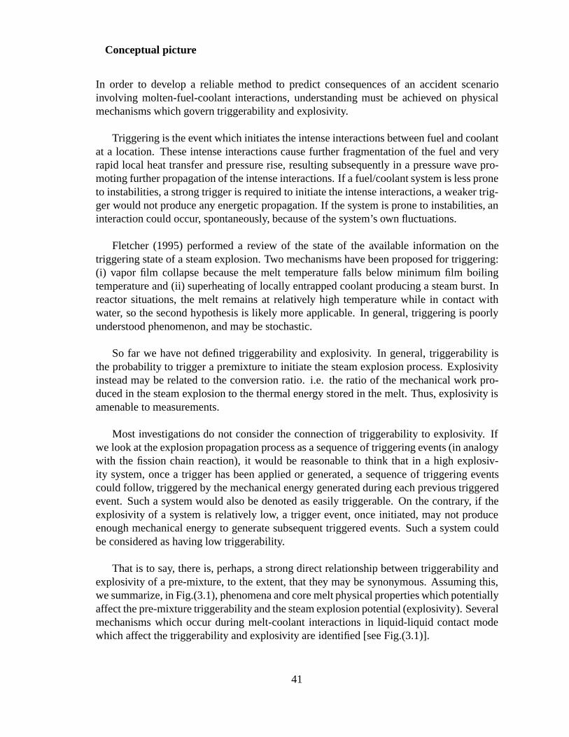
Conceptual picture
In order to develop a reliable method to predict consequences of an accident scenarioinvolving molten-fuel-coolant interactions, understanding must be achieved on physicalmechanisms which govern triggerability and explosivity.
Triggering is the event which initiates the intense interactions between fuel and coolantat a location. These intense interactions cause further fragmentation of the fuel and veryrapid local heat transfer and pressure rise, resulting subsequently in a pressure wave pro-moting further propagation of the intense interactions. If a fuel/coolant system is less proneto instabilities, a strong trigger is required to initiate the intense interactions, a weaker trig-ger would not produce any energetic propagation. If the system is prone to instabilities, aninteraction could occur, spontaneously, because of the system’s own fluctuations.
Fletcher (1995) performed a review of the state of the available information on thetriggering state of a steam explosion. Two mechanisms have been proposed for triggering:(i) vapor film collapse because the melt temperature falls below minimum film boilingtemperature and (ii) superheating of locally entrapped coolant producing a steam burst. Inreactor situations, the melt remains at relatively high temperature while in contact withwater, so the second hypothesis is likely more applicable. In general, triggering is poorlyunderstood phenomenon, and may be stochastic.
So far we have not defined triggerability and explosivity. In general, triggerability isthe probability to trigger a premixture to initiate the steam explosion process. Explosivityinstead may be related to the conversion ratio. i.e. the ratio of the mechanical work pro-duced in the steam explosion to the thermal energy stored in the melt. Thus, explosivity isamenable to measurements.
Most investigations do not consider the connection of triggerability to explosivity. Ifwe look at the explosion propagation process as a sequence of triggering events (in analogywith the fission chain reaction), it would be reasonable to think that in a high explosiv-ity system, once a trigger has been applied or generated, a sequence of triggering eventscould follow, triggered by the mechanical energy generated during each previous triggeredevent. Such a system would also be denoted as easily triggerable. On the contrary, if theexplosivity of a system is relatively low, a trigger event, once initiated, may not produceenough mechanical energy to generate subsequent triggered events. Such a system couldbe considered as having low triggerability.
That is to say, there is, perhaps, a strong direct relationship between triggerability andexplosivity of a pre-mixture, to the extent, that they may be synonymous. Assuming this,we summarize, in Fig.(3.1), phenomena and core melt physical properties which potentiallyaffect the pre-mixture triggerability and the steam explosion potential (explosivity). Severalmechanisms which occur during melt-coolant interactions in liquid-liquid contact modewhich affect the triggerability and explosivity are identified [see Fig.(3.1)].
41
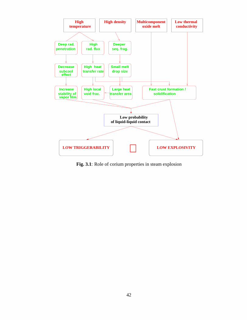
LOW EXPLOSIVITY
solidificationFast crust formation /
conductivityLow thermalMulticomponent
oxide meltHigh densityHigh
temperature
seq. frag.Deeper
Small meltdrop size
Large heattransfer area
High rad. flux
Deep rad.penetration
Decreasesubcool
effecttransfer rate
Increasestability ofvapor film
heatHigh
High localvoid frac.
LOW TRIGGERABILITY
Low probability of liquid-liquid contact
∼Fig. 3.1: Role of corium properties in steam explosion
42
These are:
� At high temperatures, radiative heat flux can penetrate deeply into subcooled water,heating it up, thereby, reducing the effect of water subcooling and increasing thestability of vapor film around a molten corium drop;
� High emissivity and high temperature of core melt also lead to high rate of heattransfer from fuel to water and, therefore, local voiding, which lowers the probabilityof liquid-liquid contact between melt and water even for a mild shock wave;
� High density of core melt appears to cause deeper sequential fragmentation of meltdrops. This results in much smaller drop sizes and significantly larger heat transfersurface area. The latter generates excessive boiling and local voiding.
� High heat removal rate from the surface of a corium melt drop also hastens its solid-ification and surface crust formation.
� Binary oxidic melt reaches a ’stiff’ state in a very short time which prevents furtherdeformation and fragmentation of the melt drop.
3.4 Effect of steam explosion on debris bed formation
3.4.1 Background on ex-vessel debris bed formation and coolability
Due to melt breakup and quenching in water, particulate (solidified) debris would be formedupon the flooded containment basemat. Current knowledge is, however, insufficient to pre-clude penetration of the melt without completely quenching through the water pool, and thesubsequent formation of a core melt pool and solidified debris cake. In addition, a melt poolcould be generated through remelting of a non-coolable particulate bed. Consequently, theconfigurations of core debris that have to be considered include (i) a bed of hot particulatedebris; (ii) a pool of molten core material; (iii) a debris cake; and (iv) various combinationsand transformations (from one to another) of the basic configurations.
A comprehensive review of knowledge base of ex-vessel debris coolability in a BWRplant was performed in the previous scoping study (Okkonen et al., 1996). It was foundthat ex-vessel melt (debris) coolability is a critical safety issue for the current and the futurelight water reactor plants, with respect to management, and termination, of a postulatedsevere (core melt) accident. After vessel failure, the core melt pool attacks the concretebasemat, whose ablation can be terminated only by cooling the melt to below the concretedissolution temperature.
The phenomenological and scenario uncertainties related to assessment of ex-vesseldebris coolability can be categorized into the following groups:
43
� melt relocation and initial conditions for ex-vessel debris cooling
– melt fragmentation in coolant and the formation of debris bed
– melt spreading
� design characteristics of drywell and core catchers
� accident management concept
– coolant injection scheme
– coolant injection timing
� thermal hydraulic conditions and physical properties of
– coolant
– concrete
– core melt (mixed with other materials)
Of interest to the present study is the effect of steam explosion and of water pool pa-rameters on the debris coolability.
3.4.2 The effect of a steam explosion on debris bed characteristics
Steam explosions in the drywell cavity, if they occur, produce small-size particles. Steamexplosions are more likely to occur in the early phase of melt relocation, when water sub-cooling is largest and the melt mass discharge rate may also be largest. The small-sizeparticles would further decrease the porosity of the particle bed in the drywell cavity. Also,layers of particles of different characteristic sizes may form. Such a debris bed is difficultto cool.
3.4.3 Coolability of inhomogeneous debris bed
The physical picture of thermal hydraulics in particle bed was reviewed by the authors early,e.g. Okkonen et al. (1995). Selected aspects were discussed, with particular emphasis oncoolability of an inhomogeneous debris bed.
In fact, hydrodynamics and heat transfer in particulate debris beds with volumetric orbottom heating have been studied extensively in the past. The most important physicalmechanism limiting the coolability of a particulate debris bed is related to the dryout phe-nomenon. Bed dry-out can occur when vapor jets leaving the top surface of the bed limitthe liquid counter flow below the level necessary to quench and cool the bed. This floodinglimitation has been adopted as the governing mechanism for the dryout models, in which
44
the dryout heat flux forms the coolability criterion; when the power generation rate in thecore debris exceeds the dryout heat flux (defined against the cross-sectional bed area), alocal or global dryout occurs. The dryout heat flux depends on a number of factors, inparticular, the bed height, the size, shape and spatial distribution of particles, as well asambient pressure and liquid pool subcooling. The dryout heat flux increases with particlediameter, bed porosity, ambient pressure and liquid mass flux entering the bottom of thebed. For beds with large particles (say, 1 cm), the dryout heat flux can even exceed theflat plate critical heat flux (1.2 MW/m2), due to the influence of debris bed heterogene-ity on vapor evacuation and hydrodynamic stability. Particularly low dryout heat fluxes,on the other hand, have been observed for stratified beds, which could be formed as a re-sult of melt fragmentation in the water pool due to size dependence of the particle terminalspeed. In this context, the large reduction of dryout heat flux has been explained by reducedporosity (small particles within larger ones particularly at the interface of layers) and theinfluence of capillary forces. Most strikingly, a stratified bed could be non-coolable even ifa homogeneous bed containing only the smaller particles would be coolable.
Most of the experimental and theoretical studies have been focused on an idealized,one-dimensional configuration, instead of the potentially wide spectrum of prototypicalparticulate beds in ex-vessel reactor cases. In fact, multi-dimensional effects provide betterconditions for debris bed coolability. The potential effects would, of course, depend onthe type (debris bed form, particle distribution, etc.) and the extent (magnitude) of multi-dimensionality. If a bed on the containment basemat were radially stratified, for example,water could ingress through zones with higher local particle size and porosity, lower heatgeneration rate (no decay heat generation), or some specific measures such as downcomertubes (or other structures designed for the flooding purpose). After that, the debris coolingcould be driven by bottom flooding and radial flow of coolant.
The physical picture of particulate bed thermal-hydraulics becomes more complicated,when taking into account gas release from zones where hot debris interacts with concrete.Large-scale gas flows might be capable of preventing penetration of water into lower re-gions of the debris bed, though gas flows might also cause strong oscillations of the liquidpool above the bed. Such oscillations could lead to unusually high dryout heat fluxes par-ticularly with deep water pools and shallow beds of fine particles. However, low gas releaserates are expected in cases of interest here because of the silicate-dominated compositionof the basaltic concrete used in the ABB-Atom BWR containments. The molten concreteslag could, on the other hand, form a crust layer that could move towards the top of the par-ticulate core debris bed. Limited experimental observations show that the crust formed bybasaltic concrete slag is mechanically unstable, however the crust would, to some extent,isolate debris from the overlying water pool and decrease its permeability.
In general, the assessment by the authors indicates that an upper water layer aloneappears unable to cool a prototypical debris bed (with particle 1-5 mm size). Additionof sub-millimiter size particles would certainly make coolability more difficult. Perhaps,it would make the bed become uncoolable early than in the case of the absence of steamexplosion. Nonetheless, the expected low frequency of steam explosion and its likelihoodin early phase of melt relocation make it less noticeable effect on the already difficult issue
45
of ex-vessel debris coolability.
3.4.4 Summary
Generally speaking, ex-vessel steam explosions have negative effect on the debris coola-bility by bringing in small-size particles. However, due to the low probability of steamexplosion the effect may be marginal.
3.5 Effect of the ex-vessel water pool parameters on debriscoolability
3.5.1 Effect of the water pool parameters
The depth of water pool established in the drywell cavity may be different (varying from4 m to 10 m), depending on the containment design features, severe accident managementactions and eventually severe accident progression. In a previous study (Okkonen et al.,1995), effect of water pool depth on the debris bed formation was examined for scenariosof coherent melt release. It was pointed out that for 4-m depth pool a large fraction of meltmay reach the cavity bottom unfragmented. Even for the 7-m deep water pool, some frac-tion of melt may remain unfragmented. In particular, a relatively high local void fractionin the region of jet penetration may reduce the fragmentation efficiency of the jet. It shouldbe noted, however, that in the study mentioned (Okkonen et al., 1995), the selected acci-dent progression scenarios featured large, superheated, core melt pool in the vessel lowerplenum. Thus, large jet diameters were predicted to occur (0.3 to 0.7 m). In the presentstudy, it was shown that the jet diameters are most likely to be 5 to 10 cm at entry to thepool surface. The jet break-up length is therefore essentially shorter, and melt is predictedto fragment long before it reaches the cavity bottom, regardless whether shallow (4 m) ordeep (7 to 10 m) water pools are established beneath the reactor vessel.
The initial water subcooling is very high (100-120 degrees centigrades), which canhowever decrease very soon during the course of melt discharge and deposition in thedrywell cavity. In particular, the central part of the cavity may be heated to saturation dueto the large radiation heat transfer from the melt jet and corium particles in the mixing zoneas well as from the surface of the debris formed on the floor.
It should be noted however that natural circulation in the water pool could be veryeffective, in the long-term, to carry the heat from the central region to the peripheral re-gion. Estimates based on heat balance indicate that the pool average temperature increasesslowly, since significant part of the melt/debris energy release is removed by steam in themixing region. For 100K subcooling, the time period required for heating up the 300 m3
46
water pool (1.25 GJ for 1K) by the energy removed from the surface of the debris of 12 m2
(300 kW/m2) bed is roughly 10 hours.
In general, relatively small-size particles are expected to form in the water pool due tohigh velocity of melt upon contact with water and the high melt density. The quenchingof small melt particles is very efficient in subcooled water. During gradual release, inparticular, the water pool may be closer to saturation, but the long fall distances (throughthe whole pool) can effect good quenching. Oxidation of metallic melt constituents, whichhas not been quantified, could be efficient in case of small particles (and saturated coolantconditions) and contribute also to the heat transferred to the water pool. Both quenchingand oxidation would be less efficient if the particle sizes were larger, because the surface-to-volume ratio would be smaller and the particles could also fall faster through the pool.
3.5.2 Current knowledge and uncertainties
Thermal-hydraulics in particulate beds
The dryout of a particulate bed submerged in a water pool is a local phenomenon. Theonset of dryout occurs when the local boiling rate exceeds the liquid inflow rate. In thedryout state a vapor pocket surrounds the particles, and deficient cooling causes increasein debris temperature, which in turn causes an expansion of the dryout region (Dhir, 1983).The dryout heat flux phenomenon in debris beds of small-diameter (Dp < 1 mm) andlarge-diameter (Dp > 1 mm) particles is fairly well understood; a comprehensive re-view of the debris dryout models has been presented by Lipinski (1983). Most modellingefforts are based on a steady-state, lumped parameter (point-model) approach, but alsoone-dimensional and time-dependent models have been developed. The most sophisticatedmodels include treatment of both laminar and turbulent flow regimes, capillary force, two-phase friction, channels at the top of the debris, and cooling by liquid entering into thebed from the bottom. The effects of particle size (in a homogeneous bed), stratification,ambient pressure, liquid subcooling and amount of liquid entering from the bottom canbe predicted by the coolability model developed by Lipinski (1984). The average error inpredicting the dryout power for a given bed configuration is around 33 % for moderatelydeep beds of spheres (comprising most of the existing data base).
The behavior of particulate beds has been investigated, experimentally and numerically,for the pre-dryout transient (before generation of the first dry spot; see, e.g., Hofmann &Schulenberg (1983) and quenching transients in superheated debris beds. Quench coolabil-ity maps developed in Ginsberg & Chen (1984) show strong dependence of coolability oninitial bed temperature, bed height and particle size. The deeper are the particulate beds,the easier does the bed melting occur (before the quench process is complete). For 1-mm-diameter particle beds, the height of the debris bed with a moderate initial temperature (say,2000K) must be less than 0.2 m to provide debris quenching (with volumetric heat gener-ation in the range of 1-1.5 MW=m
3). Such calculational results have not been validated
47
experimentally.
Some experimental studies have been performed to investigate dryout phenomena inheterogeneous and multi-dimensional particulate beds; see, e.g., refs. (Tsai, 1983) and(Wang & Schrock, 1989). It is likely that with multi-dimensional beds the chances forcoolability are better. The experimental observations are preliminary and applicable onlyfor some specific cases. Several types of debris bed configurations, which are relevant toex-vessel cases of interest (such as beds consisting of stratified layers of metallic particlesand decay-heated oxidic particles), have not been investigated.
Related uncertainties
When analyzing debris bed coolability, one has to deal with large uncertainties in initial andboundary conditions of the debris bed. Uncertainties accumulate from those of in-vesselmelt progression, vessel lower head failure and ablation, melt-water interactions (fragmen-tation and steam explosion) and debris bed formation. Furthermore, the plant-specific de-sign (and accident management) features and feedbacks from debris coolability-relatedphenomena diversify the (transient) boundary conditions of interest. A set of parametersimportant for debris bed coolability problems is presented below (numerical values areapproximate and selected for conditions of interest here):
Initial conditions- Initial debris configuration (including stratification pattern)- Height of stratified layers (particle beds, melt pool, metallic vs. oxidic layers)- Characterization of particle layers (porosity, particle size, shape and distribution)- Decay heat generation rate (� 1MW=m
3)- Debris composition (UO2=ZrO2=Zr=SS) and temperature- Volume of the core melt pool (up to � 30 m3) or particulate bed- Spreading area of the core melt pool (up to � 40 m2) or particulate bedBoundary conditions- Containment pressure (� 0:1� 0:7MPa)- Depth (4-10 m) and subcooling (� 0� 100 K) of the water pool- Concrete type (composition, properties)- Scenarios of melt release in later phase (physical impact)- Design features of the containment floor
As obvious, the parameters for debris coolability analysis are strongly scenario-dependent.
There exists a wide spectrum of thermal-hydraulic and physicochemical phenomenainvolved in the debris coolability issue. The idea of injecting water above ex-vessel coredebris was proposed and subjected to intensive research some years ago, whereas the de-graded core (in-vessel debris) coolability and MCCI have been investigated for more than adecade. Studies of similar heat transfer problems (natural convection in melt pool, crust for-mation and dynamics, etc.) are being simultaneously pursued for other safety issues such
48
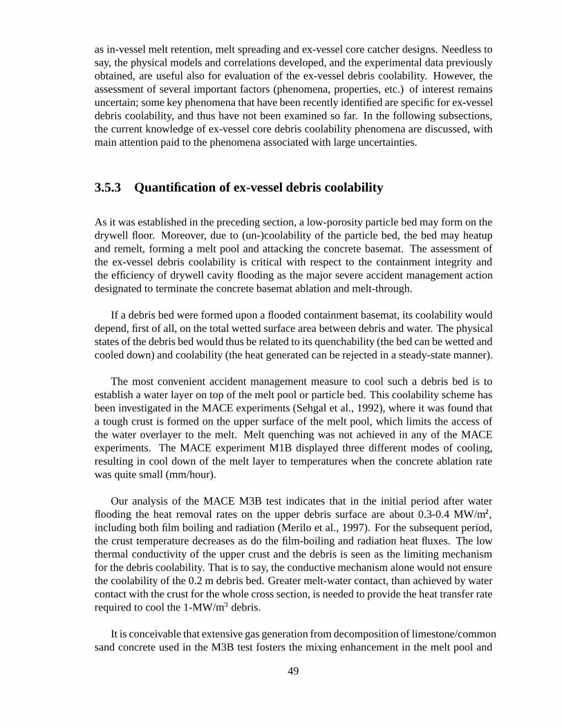
as in-vessel melt retention, melt spreading and ex-vessel core catcher designs. Needless tosay, the physical models and correlations developed, and the experimental data previouslyobtained, are useful also for evaluation of the ex-vessel debris coolability. However, theassessment of several important factors (phenomena, properties, etc.) of interest remainsuncertain; some key phenomena that have been recently identified are specific for ex-vesseldebris coolability, and thus have not been examined so far. In the following subsections,the current knowledge of ex-vessel core debris coolability phenomena are discussed, withmain attention paid to the phenomena associated with large uncertainties.
3.5.3 Quantification of ex-vessel debris coolability
As it was established in the preceding section, a low-porosity particle bed may form on thedrywell floor. Moreover, due to (un-)coolability of the particle bed, the bed may heatupand remelt, forming a melt pool and attacking the concrete basemat. The assessment ofthe ex-vessel debris coolability is critical with respect to the containment integrity andthe efficiency of drywell cavity flooding as the major severe accident management actiondesignated to terminate the concrete basemat ablation and melt-through.
If a debris bed were formed upon a flooded containment basemat, its coolability woulddepend, first of all, on the total wetted surface area between debris and water. The physicalstates of the debris bed would thus be related to its quenchability (the bed can be wetted andcooled down) and coolability (the heat generated can be rejected in a steady-state manner).
The most convenient accident management measure to cool such a debris bed is toestablish a water layer on top of the melt pool or particle bed. This coolability scheme hasbeen investigated in the MACE experiments (Sehgal et al., 1992), where it was found thata tough crust is formed on the upper surface of the melt pool, which limits the access ofthe water overlayer to the melt. Melt quenching was not achieved in any of the MACEexperiments. The MACE experiment M1B displayed three different modes of cooling,resulting in cool down of the melt layer to temperatures when the concrete ablation ratewas quite small (mm/hour).
Our analysis of the MACE M3B test indicates that in the initial period after waterflooding the heat removal rates on the upper debris surface are about 0.3-0.4 MW/m2,including both film boiling and radiation (Merilo et al., 1997). For the subsequent period,the crust temperature decreases as do the film-boiling and radiation heat fluxes. The lowthermal conductivity of the upper crust and the debris is seen as the limiting mechanismfor the debris coolability. That is to say, the conductive mechanism alone would not ensurethe coolability of the 0.2 m debris bed. Greater melt-water contact, than achieved by watercontact with the crust for the whole cross section, is needed to provide the heat transfer raterequired to cool the 1-MW/m3 debris.
It is conceivable that extensive gas generation from decomposition of limestone/commonsand concrete used in the M3B test fosters the mixing enhancement in the melt pool and
49
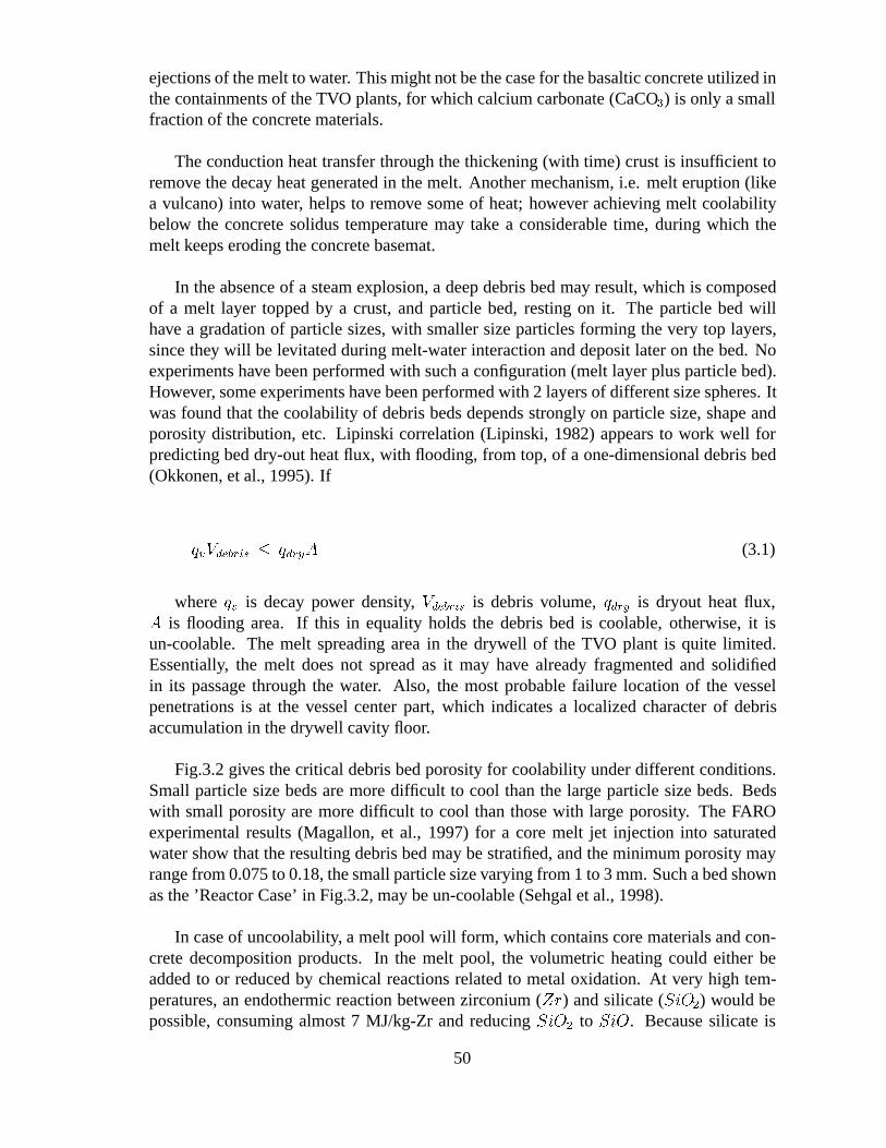
ejections of the melt to water. This might not be the case for the basaltic concrete utilized inthe containments of the TVO plants, for which calcium carbonate (CaCO3) is only a smallfraction of the concrete materials.
The conduction heat transfer through the thickening (with time) crust is insufficient toremove the decay heat generated in the melt. Another mechanism, i.e. melt eruption (likea vulcano) into water, helps to remove some of heat; however achieving melt coolabilitybelow the concrete solidus temperature may take a considerable time, during which themelt keeps eroding the concrete basemat.
In the absence of a steam explosion, a deep debris bed may result, which is composedof a melt layer topped by a crust, and particle bed, resting on it. The particle bed willhave a gradation of particle sizes, with smaller size particles forming the very top layers,since they will be levitated during melt-water interaction and deposit later on the bed. Noexperiments have been performed with such a configuration (melt layer plus particle bed).However, some experiments have been performed with 2 layers of different size spheres. Itwas found that the coolability of debris beds depends strongly on particle size, shape andporosity distribution, etc. Lipinski correlation (Lipinski, 1982) appears to work well forpredicting bed dry-out heat flux, with flooding, from top, of a one-dimensional debris bed(Okkonen, et al., 1995). If
qvVdebris � qdryA (3.1)
where qv is decay power density, Vdebris is debris volume, qdry is dryout heat flux,A is flooding area. If this in equality holds the debris bed is coolable, otherwise, it isun-coolable. The melt spreading area in the drywell of the TVO plant is quite limited.Essentially, the melt does not spread as it may have already fragmented and solidifiedin its passage through the water. Also, the most probable failure location of the vesselpenetrations is at the vessel center part, which indicates a localized character of debrisaccumulation in the drywell cavity floor.
Fig.3.2 gives the critical debris bed porosity for coolability under different conditions.Small particle size beds are more difficult to cool than the large particle size beds. Bedswith small porosity are more difficult to cool than those with large porosity. The FAROexperimental results (Magallon, et al., 1997) for a core melt jet injection into saturatedwater show that the resulting debris bed may be stratified, and the minimum porosity mayrange from 0.075 to 0.18, the small particle size varying from 1 to 3 mm. Such a bed shownas the ’Reactor Case’ in Fig.3.2, may be un-coolable (Sehgal et al., 1998).
In case of uncoolability, a melt pool will form, which contains core materials and con-crete decomposition products. In the melt pool, the volumetric heating could either beadded to or reduced by chemical reactions related to metal oxidation. At very high tem-peratures, an endothermic reaction between zirconium (Zr) and silicate (SiO2) would bepossible, consuming almost 7 MJ/kg-Zr and reducing SiO2 to SiO. Because silicate is
50
0.000 0.002 0.004 0.006 0.008 0.010Particle diameters, m
0.00
0.10
0.20
0.30
0.40
0.50
Crit
ical
por
osity
P = 0.8MW/m3P = 0.9MW/m3P = 1.0MW/m3P = 1.1MW/m3P = 1.2MW/m3P = 1.3MW/m3P = 1.4MW/m3
Reactor case
coolable regime
un−coolable regime
Fig. 3.2: The critical porosity for debris bed coolability (1D estimates).
the main constituent of the basaltic concrete of the ABB-Atom BWR containments, andits density is much less than the initial core melt density, the extent ofZr � SiO2 reac-tions might be high. Due to the high energy consumption (could exceed the decay heatingrate), this reaction could form another mechanism causing fast melt temperature drop to alevel where the reaction would cease. In contrast, at a temperature range below 2200 K theZr � SiO2 would produce metallicSi, exothermically. The oxidation reactions of zirco-nium, chromium and iron with reducing gases (steam and carbon dioxide) are also exother-mic. The actual rate of oxidation reactions would depend on the contact between concretedecomposition gases and melt. The associated limiting processes involve gas-phase dif-fusion, dissolution, and liquid-phase diffusion. Incomplete contact would reduce the rate(and perhaps also the extent) of chemical reactions, and extend the time before the reactants(mainlyZr) became depleted. The manner and extent of contact (mixing) between moltendebris and concrete constituents would depend on the melt pool height, theflow behaviourof (multi-phase, multi-component) melt, the turbulence levels and associated mass transfercoefficients, as well as chemical and phase equilibrium characteristics.
In general, molten corium-concrete interactions are very complex processes, involvingchemical reactions, heat transfer, mass transfer in multiphase systems in porous media. Inthe present work, no attempts are made towards mechanistic prediction. The assessmentmethodology and models developed by the authors and presented elsewhere (Okkonen etal., 1995, also Ph.D. Thesis by V.A. Bui, RIT, 1998) could be employed. Essentially, theconcrete ablation rate can be predicted for different melt pool/debris configurations andparameters (Fig.3.3).
51
0.0 200.0 400.0 600.0 800.0 1000.0TIME (MIN)
0.0
200.0
400.0
600.0
800.0
AB
LAT
ION
DE
PT
H (
CM
)
TOTAL DECAY POWER - 33 MW
DIAMETER OF BED - 6mDIAMETER OF BED - 8mDIAMETER OF BED - 10m
Fig. 3.3: Ablation rates of concrete basemat for cases with 1% steady-state power.
3.5.4 Summary
Due to the high density of the core melt and the relatively long fall path from the reac-tor pressure vessel to the lower dry-well with highly-subcooled water pool, characteristicsizes of debris fragments resulting from molten-fuel-coolant-inter actions may be small.This, likely, leads to formation of a low-porosity deep debris bed, which may be hard tocool. On the other side, the deep and subcooled water pool provides rapid quenching, so-lidification and cooling of the small-size debris fragments. As a result, the fragments settlefrozen and do not agglomerate. The fragment debris may therefore remain in quenched andcoolable state for a long time, until the debris layer becomes sufficiently thick. It shouldalso be noted that the frozen fragments are likely to pile up and the cooling process ismulti-dimensional, with possibility for coolant to penetrate to the bottom layer.
3.6 References
Dhir, V.K. ”On the Coolability of Degraded LWR Cores.” Nuclear Safety, Vol. 24, pp.319-337, 1983
D.F Fletcher,”Steam Explosion Triggering: a Review of Theoretical and ExperimentalInvestigations”, Nuclear Engineering and Design, v155, n1-2, 1995.
Gorham-Bergeron.”A Debris Bed Model to Predict the Effect of Gas Influx from Belowon the Dryout Heat Flux.” Proceedings of the International Meeting on Thermal Nu-
52
clear Reactor Safety, Chicago, Illinois, August 29-September 2, 1982. NUREG/CP-0027.
Ginsberg, T., and J.C. Chen.”Quench Cooling of Superheated Debris Beds in Contain-ment during LWR Core Meltdown Accidents.” Proceedings of the Fifth InternationalMeeting on Thermal Nuclear Reactor Safety, Karlsruhe, FRG, September 9-13, 1984.
Hofmann, G., and T. Schulenberg.”A Quasi-Steady-State Approximation to the TransientDryout Behavior in Debris Beds.” Paper 18.6. Proceedings of the International Meet-ing on Light Water Reactor Severe Accident Evaluation, Cambridge, Massachusetts,August 28-September 1, 1983.
Hofmann, G.”Dryout in Very Deep Particulate Beds - Experimental Results and TheirInterpretation with Measured Axial Pressure Differences.” Paper 19.I. Proceedingsof Third International Topical Meeting on Reactor Thermal Hydraulics, Newport,Rhode Island, October 15-18, 1985.
Jakobsson, J.O., I. Catton and D. Squarer.”The Pressure Dependence of Dryout HeatFlux.” Paper 18.4. Proceedings of the International Meeting on Light Water ReactorSevere Accident Evaluation, Cambridge, Massachusetts, August 28-September 1,1983.
Lipinski R.J., ”A Model for Boiling and Dryout in Particle Beds”, NUREG=CR-2646(SAND80-0765), Sandia National Laboratories, NM, 1982.
Lipinski, R.J.”A Review of Debris Coolability Models.” Paper 18.2. Proceedings of theInternational Meeting on Light Water Reactor Severe Accident Evaluation, Cam-bridge, Massachusetts, August 28-September 1, 1983.
Lipinski, R.J.”A Coolability Model for Postaccident Nuclear Reactor Debris.” NuclearTechnology, Vol.65, pp.53-66, 1984.
Magallon, D., et al.,”The FARO Programme Recent Results and Synthesis”, CSARPMeeting, Bethesda, Maryland, May 5-8, 1997.
M. Merilo, M.T. Farmer and B.W. Spencer,”Status Report on the MACE M3B Experi-ment,” CSARP Meeting, Bethesda, Maryland, May 5-8, 1997.
T. Okkonen, T.N. Dinh, V.A. Bui and B.R. Sehgal,”Quantification of the Ex-vessel SevereAccident Risks for the Swedish Boiling Water Reactor”, SKI Report 95:76, 1995.
T.J. Okkonen and B.R. Sehgal (1996),”Influence of Melt Freezing Characteristics onSteam Explosion Energetics”. Proceedings of the Fourth International Conferenceon Nuclear Engineering (ICONE-4). New Orleans, Louisiana, March 10-14, 1996.
T.J. Okkonen and B.R. Sehgal (1997),”Experiments on Melt Droplets Falling into a WaterPool”, OECD/CSNI Specialist Meeting on Fuel-Coolant Interactions. JAERI-Tokay,Japan, May 19-21, 1997.
53
Sehgal, B.R., and B.W. Spencer.”ACE Program Phase D: Melt Attack and Coolabil-ity Experiments (MACE) Program”. Proceedings of the Second OECD(NEA)CSNISpecialist Meeting on Molten Core Debris-Concrete Interactions, Karlsruhe, Ger-many, April 1-3, 1992. KfK 5108. NEA/CSNI/R(92)10.
B.R. Sehgal, Z.L. Yang, T.N. Dinh and D. Paladino,”Investigation of Ex-Vessel MeltCoolability by Bottom Coolant Injection”, International Conference on Nuclear En-gineering ICONE-6, San Diego, May 1998.
Tarbell, W.W., et al.”Sustained Concrete Attack by Low-Temperature, Fragmented CoreDebris”. NUREG/CR-3024. SAND82-2476. July 1987.
Tsai, F.P., I. Catton and D. Squarer.”On Dryout Heat Flux of an Inductively HeatedHeterogeneous Bed.” Paper 18.3. Proceedings of the International Meeting on LightWater Reactor Severe Accident Evaluation, Cambridge, Massachusetts, August 28-September 1, 1983.
T. P. Speis and S. Basu,”Fuel Coolant Interaction (FCI) Phenomena in Reactor Safety:Current Understanding and Future Research Needs”, Proceedings of the OECE/CSNISpecialist Meeting on Fuel Coolant Interactions, Tokai-Mura, Japan, May 1997.
Wang, C.H., and V.E. Schrock.”Modelling of Debris Bed Cooling.” UCB-NE-4144.University of California at Berkeley. 1989.
Yao, L.S., and K.H. Sun.”On the Prediction of the Hydrodynamics Flooding Criterion.”ASME Journal of Heat Transfer, Vol. 104, November 1982, pp. 803-805.
W.W. Yuen and T.G. Theofanous,”The Prediction of 2D Thermal Detonations and Re-sulting Damage Potential”, Nuclear Engineering and Design, v155, n1-2, 1995.
54
Chapter 4
Task 3: Assessment of steam explosionsin the Swedish and Finnish BWR plants
4.1 Chapter objectives and approach
In this Chapter, the assessment methodology on molten fuel-coolant premixing and onsteam explosion are described. Effects of different parameters and related uncertainties areevaluated. Comparisons are made with results of previous assessments, as well as withbounding values from the containment fragility curve. Concerning the phenomenology ofa series of steam explosions: probability, energy release and loads imposed, the factorse.g. water depletion, debris dispersal, and melt jet disturbance which may fundamentallylimit the probability of, and energy release in, a steam explosion following an earlier oneare analysed. As an example, a drywell geometry of medium power ABB BWR plant isconsidered for assessment of the effects of the pool depth and of non-axisymmetric entryof a melt jet in the pool. In this respect an engineering judgement on the enhancement orreduction of the steam explosion loads due to these geometrical factors is provided.
4.2 Assessment of energetics of a steam explosion
Energetics of a steam explosion depend on pre-mixture conditions prior to the arrival of apressure wave or a triggering event. There are three processes, which are competing witheach other to determine the configuration of a melt drop prior to a triggering event duringthe premixing phase of a steam explosion. They aredeceleration, sequential fragmentation,and solidification. Detailed formulation on these time scales can also be referred to Sehgal,et al (1998).
55
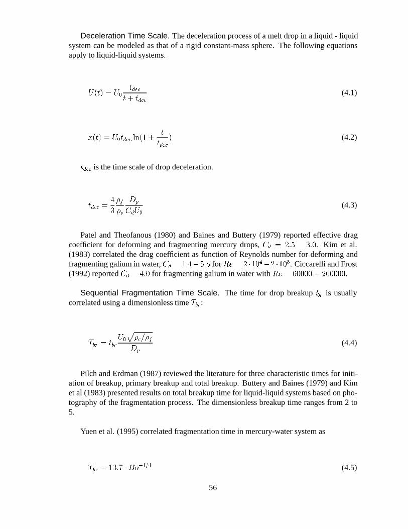
Deceleration Time Scale. The deceleration process of a melt drop in a liquid - liquidsystem can be modeled as that of a rigid constant-mass sphere. The following equationsapply to liquid-liquid systems.
U(t) = U0
tdec
t+ tdec(4.1)
x(t) = U0tdec ln(1 +t
tdec) (4.2)
tdec is the time scale of drop deceleration.
tdec =4
3
�f
�c
Dp
CdU0
(4.3)
Patel and Theofanous (1980) and Baines and Buttery (1979) reported effective dragcoefficient for deforming and fragmenting mercury drops,Cd = 2:5 � 3:0. Kim et al.(1983) correlated the drag coefficient as function of Reynolds number for deforming andfragmenting galium in water,Cd = 1:4�5:6 for Re = 2 �104�2 �105. Ciccarelli and Frost(1992) reportedCd = 4:0 for fragmenting galium in water withRe = 60000� 200000.
Sequential Fragmentation Time Scale. The time for drop breakuptbr is usuallycorrelated using a dimensionless timeTbr:
Tbr = tbrU0
p�c=�f
Dp
(4.4)
Pilch and Erdman (1987) reviewed the literature for three characteristic times for initi-ation of breakup, primary breakup and total breakup. Buttery and Baines (1979) and Kimet al (1983) presented results on total breakup time for liquid-liquid systems based on pho-tography of the fragmentation process. The dimensionless breakup time ranges from 2 to5.
Yuen et al. (1995) correlated fragmentation time in mercury-water system as
Tbr = 13:7 �Bo�1=4 (4.5)
56
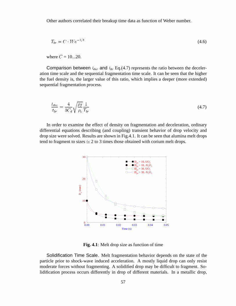
Other authors correlated their breakup time data as function of Weber number.
Tbr = C �We�1=4 (4.6)
whereC = 10...20.
Comparison between tdec and tbr Eq.(4.7) represents the ratio between the deceler-ation time scale and the sequential fragmentation time scale. It can be seen that the higherthe fuel density is, the larger value of this ratio, which implies a deeper (more extended)sequential fragmentation process.
tdec
tbr=
4
3Cd
r�f
�c
1
Tbr(4.7)
In order to examine the effect of density on fragmentation and deceleration, ordinarydifferential equations describing (and coupling) transient behavior of drop velocity anddrop size were solved. Results are shown in Fig.4.1. It can be seen that alumina melt dropstend to fragment to sizes' 2 to 3 times those obtained with corium melt drops.
0.00 0.01 0.02 0.03 0.04 0.05Time (s)
0
10
20
30
Dp
(mm
)
Dp0 = 10, UO2
Dp0 = 10, Al2O3
Dp0 = 30, UO2
Dp0 = 30, Al2O3
Fig. 4.1: Melt drop size as function of time
Solidification Time Scale. Melt fragmentation behavior depends on the state of theparticle prior to shock-wave induced acceleration. A mostly liquid drop can only resistmoderate forces without fragmenting. A solidified drop may be difficult to fragment. So-lidification process occurs differently in drop of different materials. In a metallic drop,
57
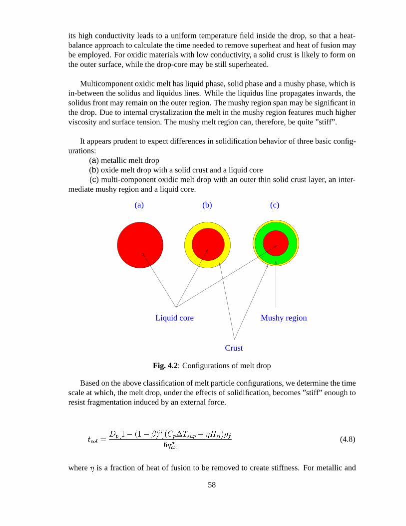
its high conductivity leads to a uniform temperaturefield inside the drop, so that a heat-balance approach to calculate the time needed to remove superheat and heat of fusion maybe employed. For oxidic materials with low conductivity, a solid crust is likely to form onthe outer surface, while the drop-core may be still superheated.
Multicomponent oxidic melt has liquid phase, solid phase and a mushy phase, which isin-between the solidus and liquidus lines. While the liquidus line propagates inwards, thesolidus front may remain on the outer region. The mushy region span may be significant inthe drop. Due to internal crystalization the melt in the mushy region features much higherviscosity and surface tension. The mushy melt region can, therefore, be quite”stiff”.
It appears prudent to expect differences in solidification behavior of three basic config-urations:
(a) metallic melt drop(b) oxide melt drop with a solid crust and a liquid core(c) multi-component oxidic melt drop with an outer thin solid crust layer, an inter-
mediate mushy region and a liquid core.
(c)
Liquid core
Crust
Mushy region
(a) (b)
Fig. 4.2: Configurations of melt drop
Based on the above classification of melt particle configurations, we determine the timescale at which, the melt drop, under the effects of solidification, becomes”stiff” enough toresist fragmentation induced by an external force.
tsol =Dp[1� (1� �)3](Cp�Tsup + �Hsl)�f
6q00av(4.8)
where� is a fraction of heat of fusion to be removed to create stiffness. For metallic and
58
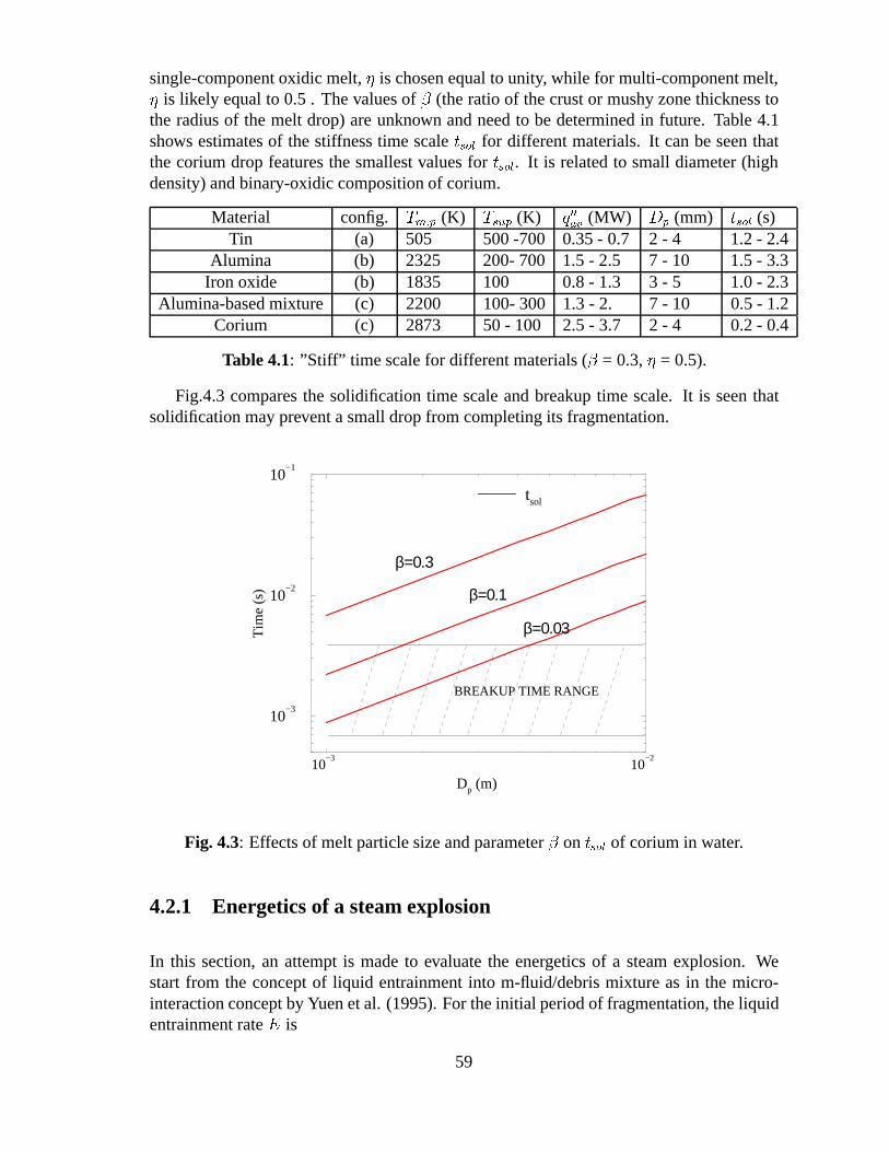
single-component oxidic melt,� is chosen equal to unity, while for multi-component melt,� is likely equal to 0.5 . The values of� (the ratio of the crust or mushy zone thickness tothe radius of the melt drop) are unknown and need to be determined in future. Table 4.1shows estimates of the stiffness time scaletsol for different materials. It can be seen thatthe corium drop features the smallest values fortsol. It is related to small diameter (highdensity) and binary-oxidic composition of corium.
Material config. Tm:p (K) Tsup (K) q00
av (MW) Dp (mm) tsol (s)Tin (a) 505 500 -700 0.35 - 0.7 2 - 4 1.2 - 2.4
Alumina (b) 2325 200- 700 1.5 - 2.5 7 - 10 1.5 - 3.3Iron oxide (b) 1835 100 0.8 - 1.3 3 - 5 1.0 - 2.3
Alumina-based mixture (c) 2200 100- 300 1.3 - 2. 7 - 10 0.5 - 1.2Corium (c) 2873 50 - 100 2.5 - 3.7 2 - 4 0.2 - 0.4
Table 4.1: ”Stiff” time scale for different materials (� = 0.3,� = 0.5).
Fig.4.3 compares the solidification time scale and breakup time scale. It is seen thatsolidification may prevent a small drop from completing its fragmentation.
10−3
10−2
Dp (m)
10−3
10−2
10−1
Tim
e (s
)
tsol
β=0.3
β=0.1
BREAKUP TIME RANGE
β=0.03
Fig. 4.3: Effects of melt particle size and parameter� on tsol of corium in water.
4.2.1 Energetics of a steam explosion
In this section, an attempt is made to evaluate the energetics of a steam explosion. Westart from the concept of liquid entrainment into m-fluid/debris mixture as in the micro-interaction concept by Yuen et al. (1995). For the initial period of fragmentation, the liquidentrainment rateE is
59
E = feFr�c
�f(4.9)
Effect of voiding in the mixing zone may be accounted through the use of void fraction:
E = feFr�c
�f(1� �v) (4.10)
Fr is the fragmentation rate, which can be estimated as
Fr = Mf=tb (4.11)
whereMf is molten fuel mass.
Assuming that all entrained liquid vaporizes in time scale of explosion and produceswork with a thermodynamic efficiency of 1/3, the work produced can be calculated as
W =1
3fe(1� �v)MfHfg
tex
tb
�c
�f(4.12)
wheretb andtex are the characteristic times of drop breakup and steam explosion.
tb = TbDp
U1
s�c(1� �v)
�f(4.13)
For tex we use the Fauske and Epstein (1993) formulation:
Lm
Us
� tex �Lm
Us � U1
(4.14)
whereUs is the shock propagation speed,U1
is the velocity of the mixture acceleratedbehind the shock andLm is the characteristic length of explosion. Assuming
60
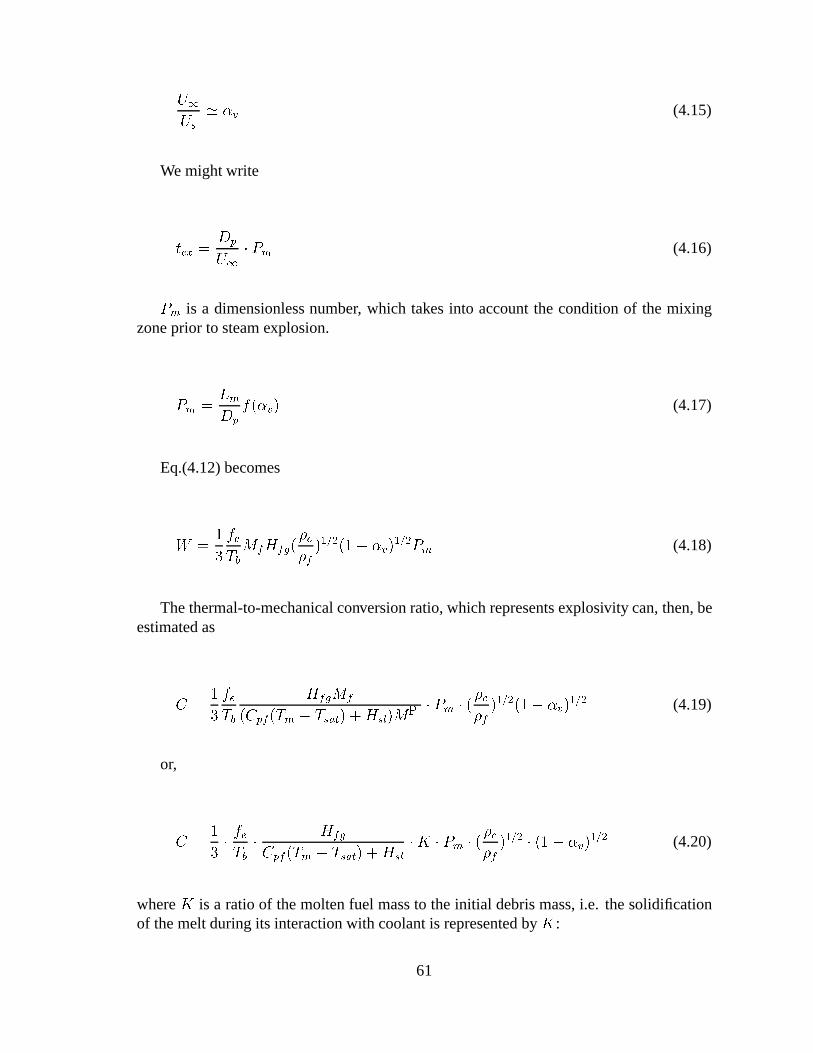
U1
Us
' �v (4.15)
We might write
tex =Dp
U1
� Pm (4.16)
Pm is a dimensionless number, which takes into account the condition of the mixingzone prior to steam explosion.
Pm =Lm
Dp
f(�v) (4.17)
Eq.(4.12) becomes
W =1
3
fe
TbMfHfg(
�c
�f)1=2(1� �v)
1=2Pm (4.18)
The thermal-to-mechanical conversion ratio, which represents explosivity can, then, beestimated as
C =1
3
fe
Tb
HfgMf
(Cpf(Tm � Tsat) +Hsl)MP� Pm � (
�c
�f)1=2(1� �v)
1=2 (4.19)
or,
C =1
3�fe
Tb�
Hfg
Cpf(Tm � Tsat) +Hsl
�K � Pm � (�c
�f)1=2 � (1� �v)
1=2 (4.20)
whereK is a ratio of the molten fuel mass to the initial debris mass, i.e. the solidificationof the melt during its interaction with coolant is represented byK:
61
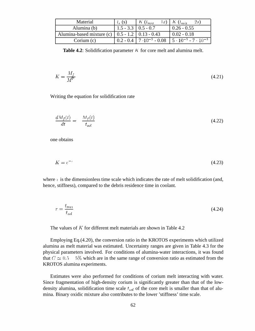
Material ts (s) K (tmix = 1s) K (tmix = 2s)Alumina (b) 1.5 - 3.3 0.5 - 0.7 0.26 - 0.55
Alumina-based mixture (c) 0.5 - 1.2 0.13 - 0.43 0.02 - 0.18Corium (c) 0.2 - 0.4 7 �10�3 - 0.08 5 � 10�5 - 7 � 10�3
Table 4.2: Solidification parameterK for core melt and alumina melt.
K =Mf
MP(4.21)
Writing the equation for solidification rate
dMf (t)
dt= �
Mf (t)
tsol(4.22)
one obtains
K = e�� (4.23)
where� is the dimensionless time scale which indicates the rate of melt solidification (and,hence, stiffness), compared to the debris residence time in coolant.
� =tmix
tsol(4.24)
The values ofK for different melt materials are shown in Table 4.2
Employing Eq.(4.20), the conversion ratio in the KROTOS experiments which utilizedalumina as melt material was estimated. Uncertainty ranges are given in Table 4.3 for thephysical parameters involved. For conditions of alumina-water interactions, it was foundthatC ' 0:5 � 5% which are in the same range of conversion ratio as estimated from theKROTOS alumina experiments.
Estimates were also performed for conditions of corium melt interacting with water.Since fragmentation of high-density corium is significantly greater than that of the low-density alumina, solidification time scaletsol of the core melt is smaller than that of alu-mina. Binary oxidic mixture also contributes to the lower ’stiffness’ time scale.
62
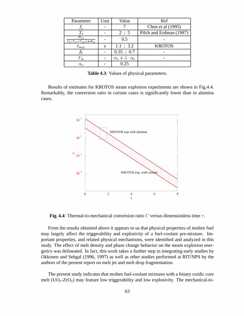
Parameter Unit Value Reffe - 7 Chen et al (1995)Tb - 2� 5 Pilch and Erdman (1987)Hfg
Cp(Tm�Tsat)+Hsl- 0.5 -
tmix s 1.1� 3.2 KROTOSK - 0.35� 0.7 -Pm - �v � 5 � �v -�v - 0.25
Table 4.3: Values of physical parameters.
Results of estimates for KROTOS steam explosion experiments are shown in Fig.4.4.Remarkably, the conversion ratio in corium cases is significantly lower than in aluminacases.
0 2 4 6 8τ
10−4
10−3
10−2
10−1
C
KROTOS exp with alumina
KROTOS exp. with corium
Fig. 4.4: Thermal-to-mechanical conversion ratio C versus dimensionless time � .
From the results obtained above it appears to us that physical properties of molten fuelmay largely affect the triggerability and explosivity of a fuel-coolant pre-mixture. Im-portant properties, and related physical mechanisms, were identified and analyzed in thisstudy. The effect of melt density and phase change behavior on the steam explosion ener-getics was delineated. In fact, this work takes a further step in integrating early studies byOkkonen and Sehgal (1996, 1997) as well as other studies performed at RIT/NPS by theauthors of the present report on melt jet and melt drop fragmentation.
The present study indicates that molten fuel-coolant mixtures with a binary oxidic coremelt (UO2-ZrO2) may feature low triggerability and low explosivity. The mechanical-to-
63
thermal conversion ratio may be very low. It also appears to us that the presence of metalliccomponent in the melt may significantly enhance triggerability and explosivity of moltencorium.
We believe that it is the first time a rational explanation for the non-explosive characterof oxidic core melt has been advanced, and qualitatively verified against existing base ofdata and observations. More experiments using simulant materials are however neededto verify the rationale and the findings of the present study. The arguments on the useof the mechanical-to-thermal conversion ratio as a representation of the triggerability andexplosivity of a melt material could be used towards a scaling law to guide future steamexplosion experiments.
4.3 Evaluation of uncertainties in the assessment of steamexplosions in the ABB BWR plants
Assessment of melt-coolant premixing is performed for Swedish LWRs, when the contain-ment drywell is filled with water, as prescribed by the severe accident management activity.The range of uncertainties are specified and presented in Table 4.3 for scenarios with oxidemelt discharge from the reactor pressure vessel.
Assessment is performed for two cases (O-1 and M-1), with different material compo-sitions for the fuel jet. In one case, the discharged melt is mainly oxidic and, in the othercase, it is metallic. From the scenario point of view, several parameters are of potential im-portance to either safety aspect of dynamic-loading or of debris coolability. These are thewater pool depth, the melt discharge rate for oxidic melt, and the superheat and flowratefor metallic melt. Sensitivity analysis has been performed and its results presented andanalyzed in section 4.7.
The melt discharge rate in the basic cases (O-1 and M-1) is given in the range from 50to 200 kg/s, which correspond to the gradual release scenarios. Such a melt discharge rateis equivalent to the melting rate of an in-vessel debris bed by the decay heating.
In the basic-case calculations, the superheat of oxidic and metallic melts is chosen tovary in the range from 0 to 150K and from 0 to 100K, respectively. As it has been shownearlier in this report, the superheat of both oxidic and metallic melts is limited when thereactor vessel penetrations made of steel fail. The metallic melt has very low viscosity andcan become very fluid already at relatively low values of superheat. The range of the depthof the water pool varies from 4 to 10 m. Such a range is dictated by the consideration thatdeficiencies in the water filling system as well as early containment leakage may result inlower water level than the design specification (11 m). This range is conservative especiallyfor estimating the surface-average and volume-average temperature (enthalpy) of the debrisfragments when they settle on the drywell floor.
64
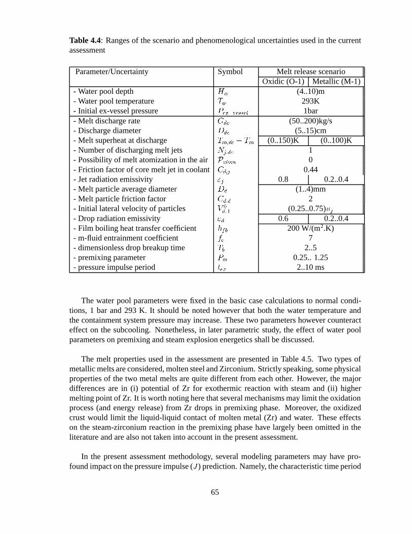
Table 4.4: Ranges of the scenario and phenomenological uncertainties used in the currentassessment
Parameter/Uncertainty Symbol Melt release scenarioOxidic (O-1) Metallic (M-1)
- Water pool depth Hw (4..10)m- Water pool temperature Tw 293K- Initial ex-vessel pressure Pex�vessel 1bar- Melt discharge rate Gdc (50..200)kg/s- Discharge diameter Ddc (5..15)cm- Melt superheat at discharge Tm;dc � Tm (0..150)K (0..100)K- Number of discharging melt jets Nj;dc 1- Possibility of melt atomization in the air Patom 0- Friction factor of core melt jet in coolant Cd;j 0.44- Jet radiation emissivity "j 0.8 0.2..0.4- Melt particle average diameter Dd (1..4)mm- Melt particle friction factor Cd;d 2- Initial lateral velocity of particles V
0d;? (0.25..0.75)uj
- Drop radiation emissivity "d 0.6 0.2..0.4- Film boiling heat transfer coefficient hfb 200 W/(m2.K)- m-fluid entrainment coefficient fe 7- dimensionless drop breakup time Tb 2..5- premixing parameter Pm 0.25.. 1.25- pressure impulse period tex 2..10 ms
The water pool parameters were fixed in the basic case calculations to normal condi-tions, 1 bar and 293 K. It should be noted however that both the water temperature andthe containment system pressure may increase. These two parameters however counteracteffect on the subcooling. Nonetheless, in later parametric study, the effect of water poolparameters on premixing and steam explosion energetics shall be discussed.
The melt properties used in the assessment are presented in Table 4.5. Two types ofmetallic melts are considered, molten steel and Zirconium. Strictly speaking, some physicalproperties of the two metal melts are quite different from each other. However, the majordifferences are in (i) potential of Zr for exothermic reaction with steam and (ii) highermelting point of Zr. It is worth noting here that several mechanisms may limit the oxidationprocess (and energy release) from Zr drops in premixing phase. Moreover, the oxidizedcrust would limit the liquid-liquid contact of molten metal (Zr) and water. These effectson the steam-zirconium reaction in the premixing phase have largely been omitted in theliterature and are also not taken into account in the present assessment.
In the present assessment methodology, several modeling parameters may have pro-found impact on the pressure impulse (J) prediction. Namely, the characteristic time period
65
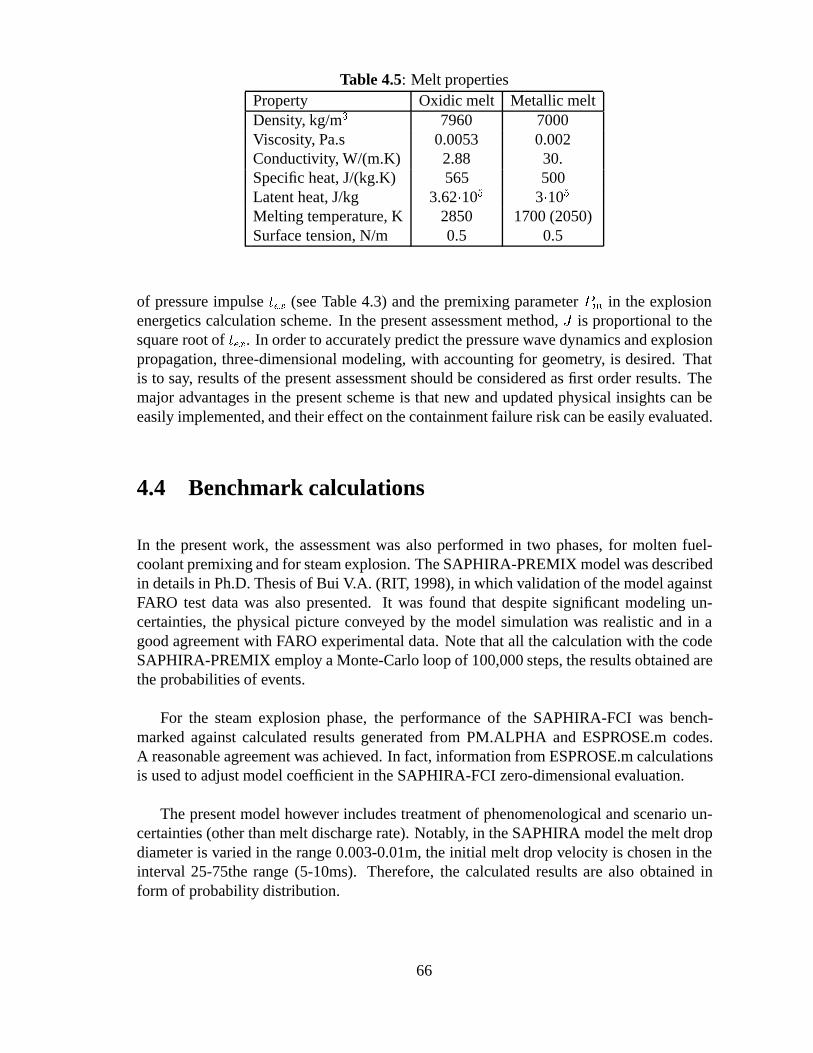
Table 4.5: Melt propertiesProperty Oxidic melt Metallic meltDensity, kg/m3 7960 7000Viscosity, Pa.s 0.0053 0.002Conductivity, W/(m.K) 2.88 30.Specific heat, J/(kg.K) 565 500Latent heat, J/kg 3.62�105 3�105
Melting temperature, K 2850 1700 (2050)Surface tension, N/m 0.5 0.5
of pressure impulse tex (see Table 4.3) and the premixing parameter Pm in the explosionenergetics calculation scheme. In the present assessment method, J is proportional to thesquare root of tex. In order to accurately predict the pressure wave dynamics and explosionpropagation, three-dimensional modeling, with accounting for geometry, is desired. Thatis to say, results of the present assessment should be considered as first order results. Themajor advantages in the present scheme is that new and updated physical insights can beeasily implemented, and their effect on the containment failure risk can be easily evaluated.
4.4 Benchmark calculations
In the present work, the assessment was also performed in two phases, for molten fuel-coolant premixing and for steam explosion. The SAPHIRA-PREMIX model was describedin details in Ph.D. Thesis of Bui V.A. (RIT, 1998), in which validation of the model againstFARO test data was also presented. It was found that despite significant modeling un-certainties, the physical picture conveyed by the model simulation was realistic and in agood agreement with FARO experimental data. Note that all the calculation with the codeSAPHIRA-PREMIX employ a Monte-Carlo loop of 100,000 steps, the results obtained arethe probabilities of events.
For the steam explosion phase, the performance of the SAPHIRA-FCI was bench-marked against calculated results generated from PM.ALPHA and ESPROSE.m codes.A reasonable agreement was achieved. In fact, information from ESPROSE.m calculationsis used to adjust model coefficient in the SAPHIRA-FCI zero-dimensional evaluation.
The present model however includes treatment of phenomenological and scenario un-certainties (other than melt discharge rate). Notably, in the SAPHIRA model the melt dropdiameter is varied in the range 0.003-0.01m, the initial melt drop velocity is chosen in theinterval 25-75the range (5-10ms). Therefore, the calculated results are also obtained inform of probability distribution.
66
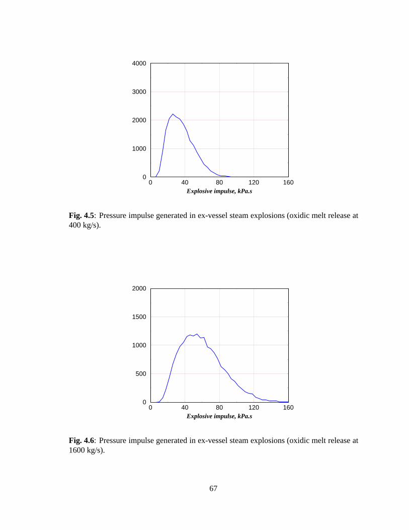
0 40 80 120 160Explosive impulse, kPa.s
0
1000
2000
3000
4000
Fig. 4.5: Pressure impulse generated in ex-vessel steam explosions (oxidic melt release at400 kg/s).
0 40 80 120 160Explosive impulse, kPa.s
0
500
1000
1500
2000
Fig. 4.6: Pressure impulse generated in ex-vessel steam explosions (oxidic melt release at1600 kg/s).
67
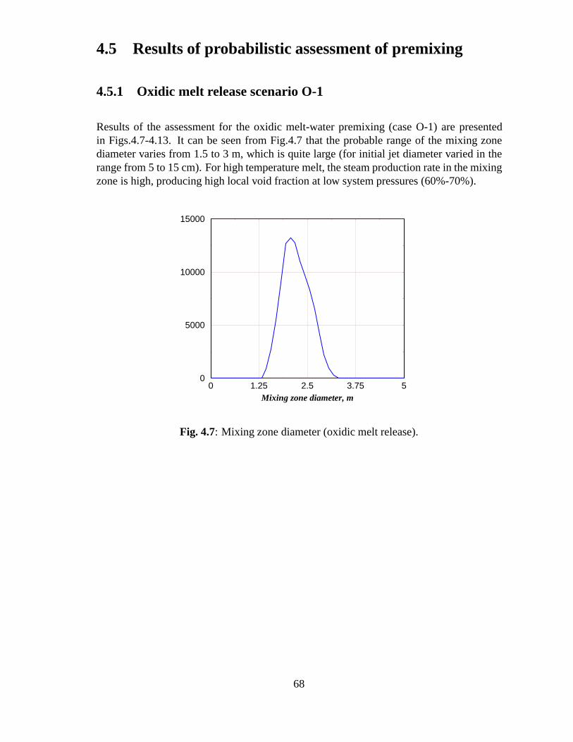
4.5 Results of probabilistic assessment of premixing
4.5.1 Oxidic melt release scenario O-1
Results of the assessment for the oxidic melt-water premixing (case O-1) are presentedin Figs.4.7-4.13. It can be seen from Fig.4.7 that the probable range of the mixing zonediameter varies from 1.5 to 3 m, which is quite large (for initial jet diameter varied in therange from 5 to 15 cm). For high temperature melt, the steam production rate in the mixingzone is high, producing high local void fraction at low system pressures (60%-70%).
0 1.25 2.5 3.75 5Mixing zone diameter, m
0
5000
10000
15000
Fig. 4.7: Mixing zone diameter (oxidic melt release).
68
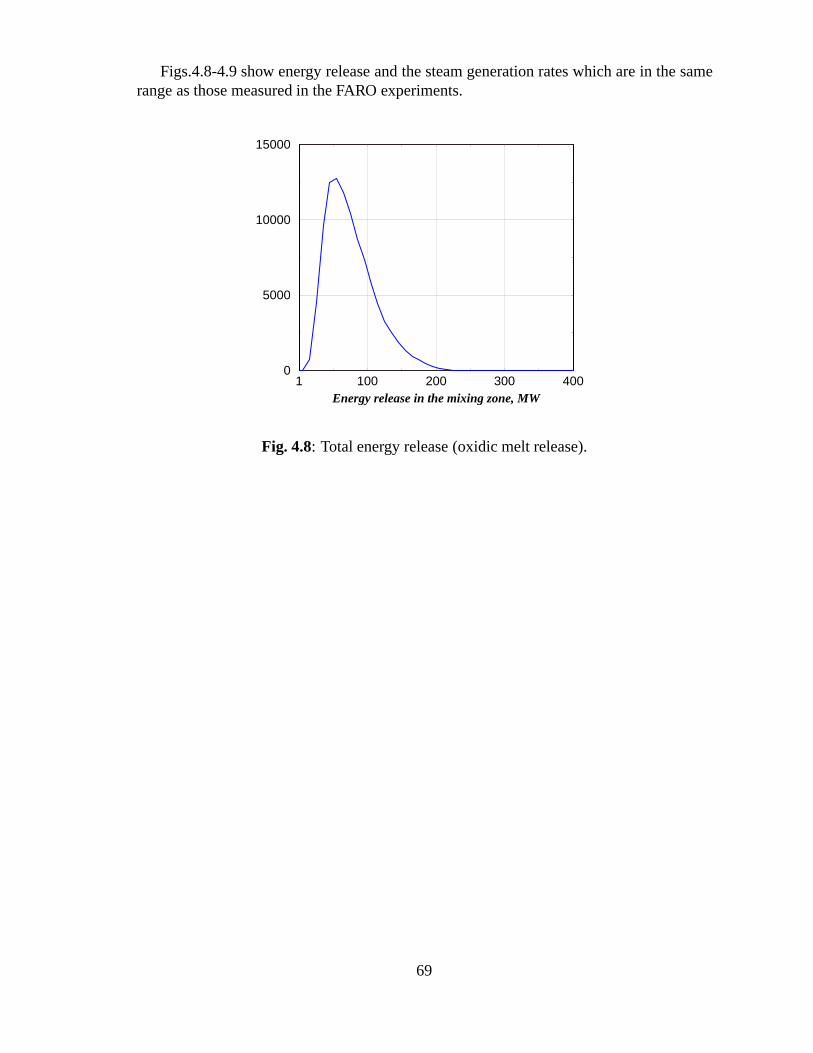
Figs.4.8-4.9 show energy release and the steam generation rates which are in the samerange as those measured in the FARO experiments.
1 100 200 300 400Energy release in the mixing zone, MW
0
5000
10000
15000
Fig. 4.8: Total energy release (oxidic melt release).
69
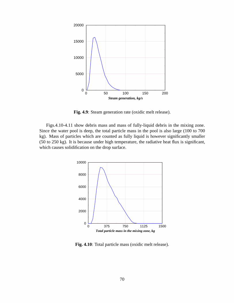
0 50 100 150 200Steam generation, kg/s
0
5000
10000
15000
20000
Fig. 4.9: Steam generation rate (oxidic melt release).
Figs.4.10-4.11 show debris mass and mass of fully-liquid debris in the mixing zone.Since the water pool is deep, the total particle mass in the pool is also large (100 to 700kg). Mass of particles which are counted as fully liquid is however significantly smaller(50 to 250 kg). It is because under high temperature, the radiative heat flux is significant,which causes solidification on the drop surface.
0 375 750 1125 1500Total particle mass in the mixing zone, kg
0
2000
4000
6000
8000
10000
Fig. 4.10: Total particle mass (oxidic melt release).
70
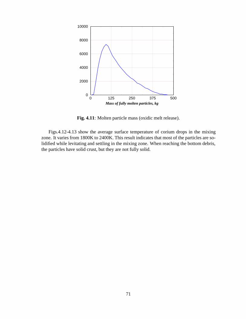
0 125 250 375 500Mass of fully molten particles, kg
0
2000
4000
6000
8000
10000
Fig. 4.11: Molten particle mass (oxidic melt release).
Figs.4.12-4.13 show the average surface temperature of corium drops in the mixingzone. It varies from 1800K to 2400K. This result indicates that most of the particles are so-lidified while levitating and settling in the mixing zone. When reaching the bottom debris,the particles have solid crust, but they are not fully solid.
71
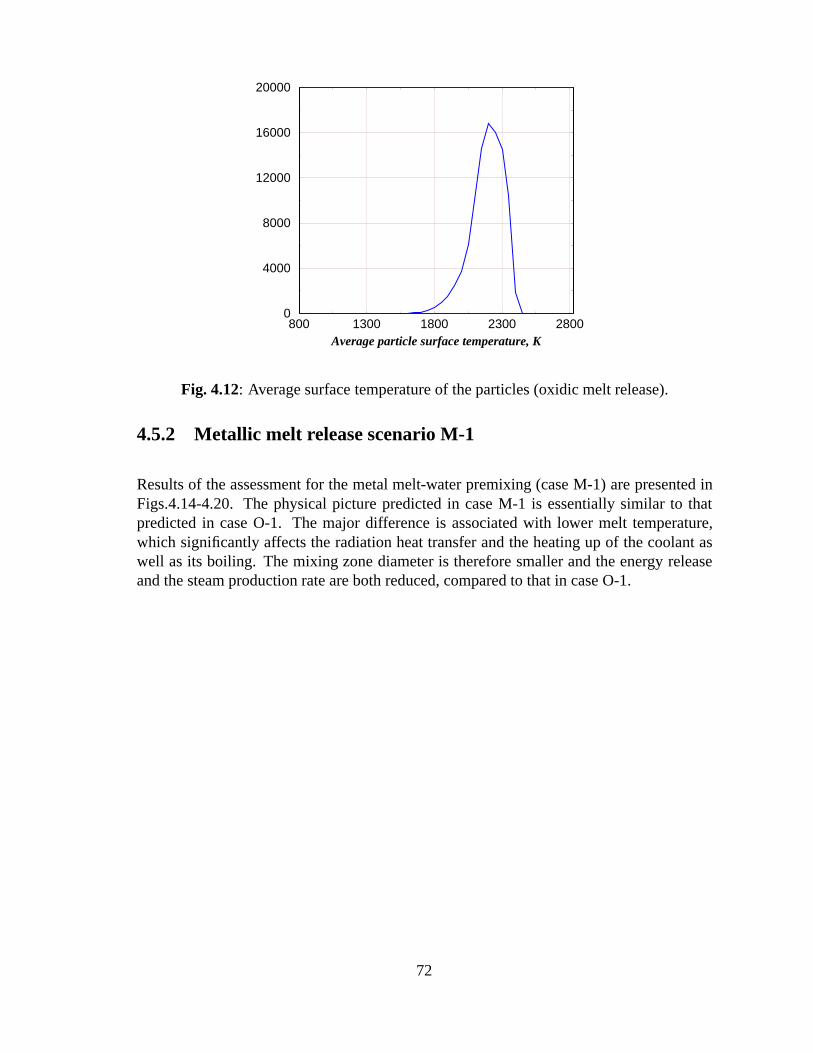
800 1300 1800 2300 2800Average particle surface temperature, K
0
4000
8000
12000
16000
20000
Fig. 4.12: Average surface temperature of the particles (oxidic melt release).
4.5.2 Metallic melt release scenario M-1
Results of the assessment for the metal melt-water premixing (case M-1) are presented inFigs.4.14-4.20. The physical picture predicted in case M-1 is essentially similar to thatpredicted in case O-1. The major difference is associated with lower melt temperature,which significantly affects the radiation heat transfer and the heating up of the coolant aswell as its boiling. The mixing zone diameter is therefore smaller and the energy releaseand the steam production rate are both reduced, compared to that in case O-1.
72
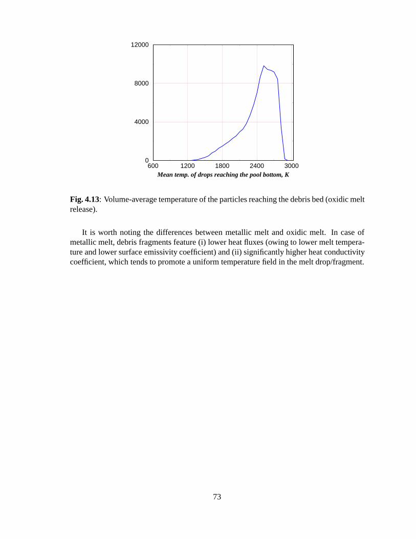
600 1200 1800 2400 3000Mean temp. of drops reaching the pool bottom, K
0
4000
8000
12000
Fig. 4.13: Volume-average temperature of the particles reaching the debris bed (oxidic meltrelease).
It is worth noting the differences between metallic melt and oxidic melt. In case ofmetallic melt, debris fragments feature (i) lower heat fluxes (owing to lower melt tempera-ture and lower surface emissivity coefficient) and (ii) significantly higher heat conductivitycoefficient, which tends to promote a uniform temperature field in the melt drop/fragment.
73
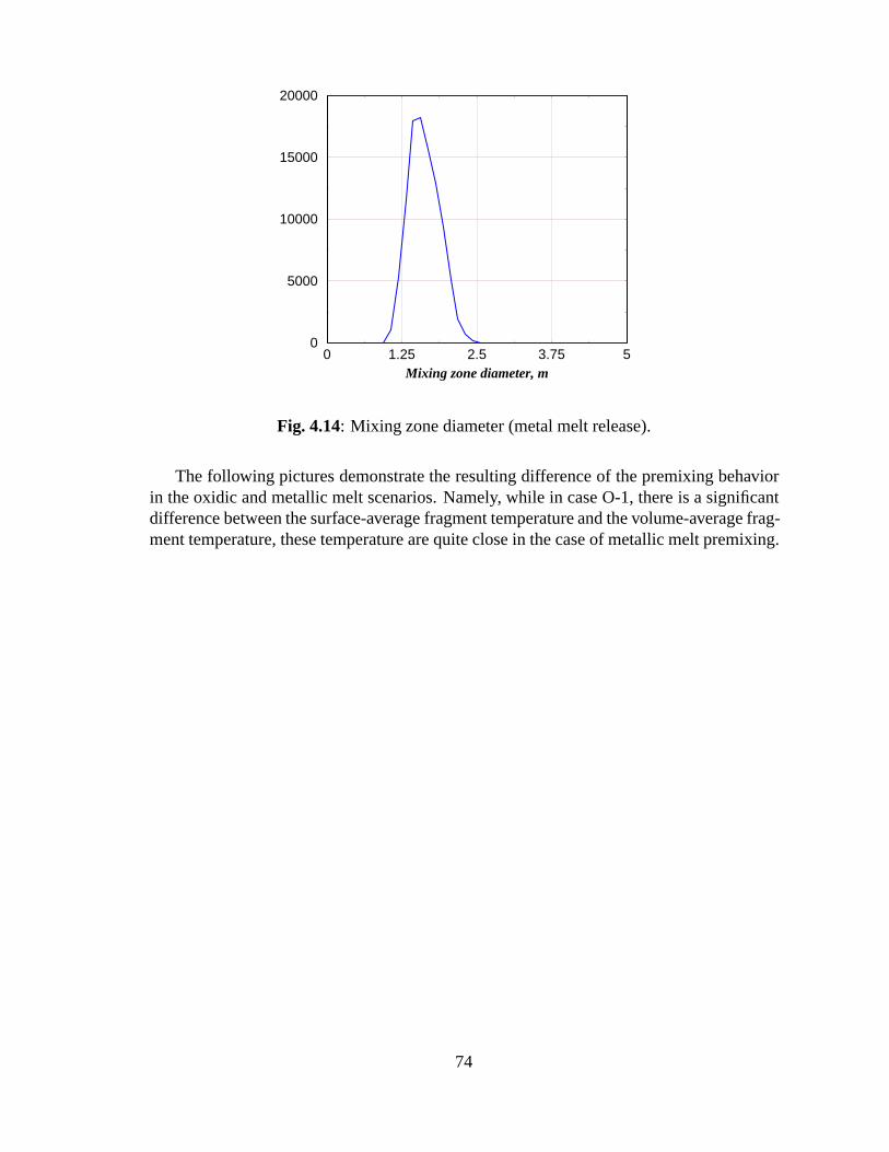
0 1.25 2.5 3.75 5Mixing zone diameter, m
0
5000
10000
15000
20000
Fig. 4.14: Mixing zone diameter (metal melt release).
The following pictures demonstrate the resulting difference of the premixing behaviorin the oxidic and metallic melt scenarios. Namely, while in case O-1, there is a significantdifference between the surface-average fragment temperature and the volume-average frag-ment temperature, these temperature are quite close in the case of metallic melt premixing.
74
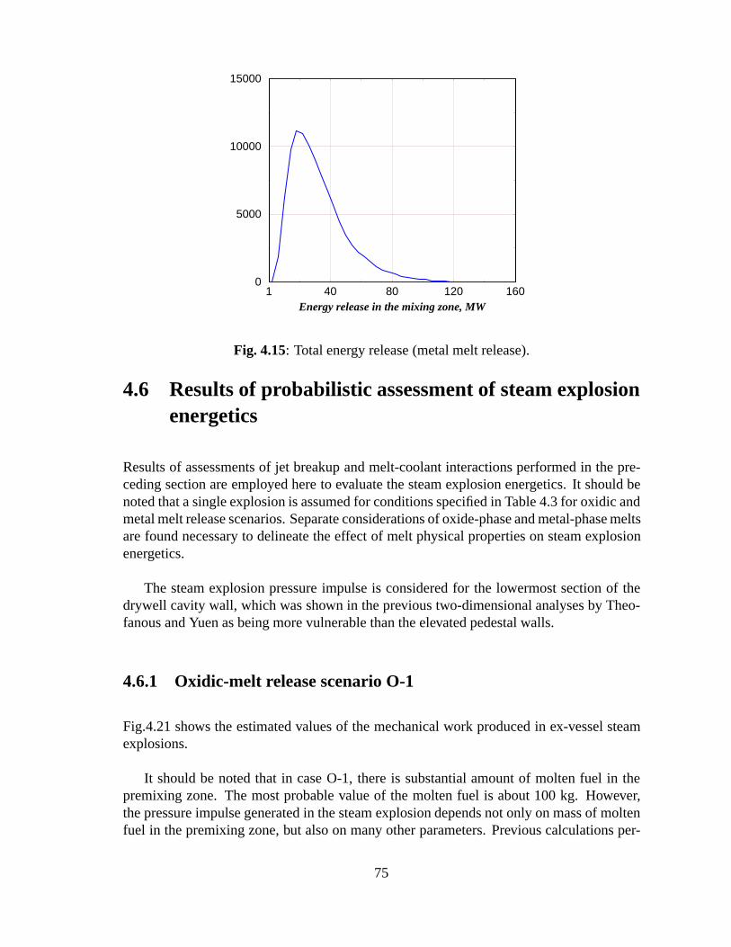
1 40 80 120 160Energy release in the mixing zone, MW
0
5000
10000
15000
Fig. 4.15: Total energy release (metal melt release).
4.6 Results of probabilistic assessment of steam explosionenergetics
Results of assessments of jet breakup and melt-coolant interactions performed in the pre-ceding section are employed here to evaluate the steam explosion energetics. It should benoted that a single explosion is assumed for conditions specified in Table 4.3 for oxidic andmetal melt release scenarios. Separate considerations of oxide-phase and metal-phase meltsare found necessary to delineate the effect of melt physical properties on steam explosionenergetics.
The steam explosion pressure impulse is considered for the lowermost section of thedrywell cavity wall, which was shown in the previous two-dimensional analyses by Theo-fanous and Yuen as being more vulnerable than the elevated pedestal walls.
4.6.1 Oxidic-melt release scenario O-1
Fig.4.21 shows the estimated values of the mechanical work produced in ex-vessel steamexplosions.
It should be noted that in case O-1, there is substantial amount of molten fuel in thepremixing zone. The most probable value of the molten fuel is about 100 kg. However,the pressure impulse generated in the steam explosion depends not only on mass of moltenfuel in the premixing zone, but also on many other parameters. Previous calculations per-
75
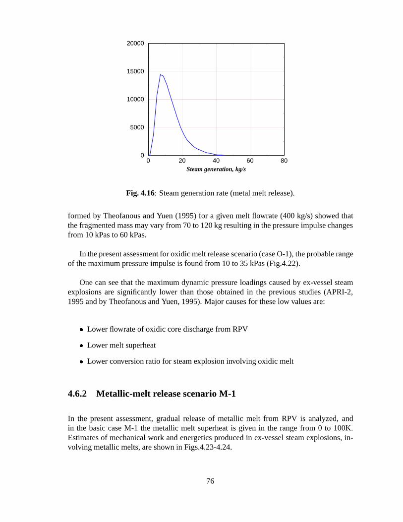
0 20 40 60 80Steam generation, kg/s
0
5000
10000
15000
20000
Fig. 4.16: Steam generation rate (metal melt release).
formed by Theofanous and Yuen (1995) for a given melt flowrate (400 kg/s) showed thatthe fragmented mass may vary from 70 to 120 kg resulting in the pressure impulse changesfrom 10 kPas to 60 kPas.
In the present assessment for oxidic melt release scenario (case O-1), the probable rangeof the maximum pressure impulse is found from 10 to 35 kPas (Fig.4.22).
One can see that the maximum dynamic pressure loadings caused by ex-vessel steamexplosions are significantly lower than those obtained in the previous studies (APRI-2,1995 and by Theofanous and Yuen, 1995). Major causes for these low values are:
� Lower flowrate of oxidic core discharge from RPV
� Lower melt superheat
� Lower conversion ratio for steam explosion involving oxidic melt
4.6.2 Metallic-melt release scenario M-1
In the present assessment, gradual release of metallic melt from RPV is analyzed, andin the basic case M-1 the metallic melt superheat is given in the range from 0 to 100K.Estimates of mechanical work and energetics produced in ex-vessel steam explosions, in-volving metallic melts, are shown in Figs.4.23-4.24.
76
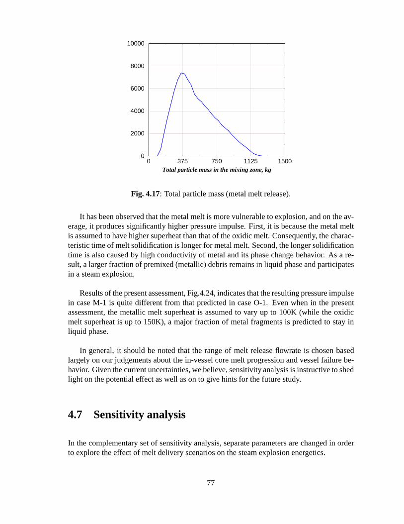
0 375 750 1125 1500Total particle mass in the mixing zone, kg
0
2000
4000
6000
8000
10000
Fig. 4.17: Total particle mass (metal melt release).
It has been observed that the metal melt is more vulnerable to explosion, and on the av-erage, it produces significantly higher pressure impulse. First, it is because the metal meltis assumed to have higher superheat than that of the oxidic melt. Consequently, the charac-teristic time of melt solidification is longer for metal melt. Second, the longer solidificationtime is also caused by high conductivity of metal and its phase change behavior. As a re-sult, a larger fraction of premixed (metallic) debris remains in liquid phase and participatesin a steam explosion.
Results of the present assessment, Fig.4.24, indicates that the resulting pressure impulsein case M-1 is quite different from that predicted in case O-1. Even when in the presentassessment, the metallic melt superheat is assumed to vary up to 100K (while the oxidicmelt superheat is up to 150K), a major fraction of metal fragments is predicted to stay inliquid phase.
In general, it should be noted that the range of melt release flowrate is chosen basedlargely on our judgements about the in-vessel core melt progression and vessel failure be-havior. Given the current uncertainties, we believe, sensitivity analysis is instructive to shedlight on the potential effect as well as on to give hints for the future study.
4.7 Sensitivity analysis
In the complementary set of sensitivity analysis, separate parameters are changed in orderto explore the effect of melt delivery scenarios on the steam explosion energetics.
77
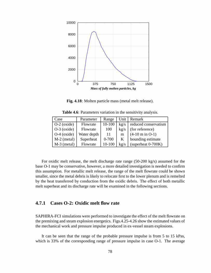
0 375 750 1125 1500Mass of fully molten particles, kg
0
2000
4000
6000
8000
10000
Fig. 4.18: Molten particle mass (metal melt release).
Table 4.6: Parameters variation in the sensitivity analysis.
Case Parameter Range Unit RemarkO-2 (oxide) Flowrate 10-100 kg/s reduced conservatismO-3 (oxide) Flowrate 100 kg/s (for reference)O-4 (oxide) Water depth 11 m (4-10 m in O-1)M-2 (metal) Superheat 0-700 K bounding estimateM-3 (metal) Flowrate 10-100 kg/s (superheat 0-700K)
For oxidic melt release, the melt discharge rate range (50-200 kg/s) assumed for thebase O-1 may be conservative, however, a more detailed investigation is needed to confirmthis assumption. For metallic melt release, the range of the melt flowrate could be shownsmaller, since the metal debris is likely to relocate first to the lower plenum and is remeltedby the heat transferred by conduction from the oxidic debris. The effect of both metallicmelt superheat and its discharge rate will be examined in the following sections.
4.7.1 Cases O-2: Oxidic melt flow rate
SAPHIRA-FCI simulations were performed to investigate the effect of the melt flowrate onthe premixing and steam explosion energetics. Figs.4.25-4.26 show the estimated values ofthe mechanical work and pressure impulse produced in ex-vessel steam explosions.
It can be seen that the range of the probable pressure impulse is from 5 to 15 kPas,which is 33% of the corresponding range of pressure impulse in case O-1. The average
78
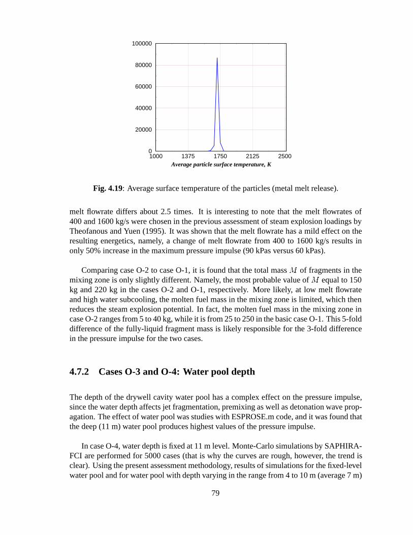
1000 1375 1750 2125 2500Average particle surface temperature, K
0
20000
40000
60000
80000
100000
Fig. 4.19: Average surface temperature of the particles (metal melt release).
melt flowrate differs about 2.5 times. It is interesting to note that the melt flowrates of400 and 1600 kg/s were chosen in the previous assessment of steam explosion loadings byTheofanous and Yuen (1995). It was shown that the melt flowrate has a mild effect on theresulting energetics, namely, a change of melt flowrate from 400 to 1600 kg/s results inonly 50% increase in the maximum pressure impulse (90 kPas versus 60 kPas).
Comparing case O-2 to case O-1, it is found that the total mass M of fragments in themixing zone is only slightly different. Namely, the most probable value of M equal to 150kg and 220 kg in the cases O-2 and O-1, respectively. More likely, at low melt flowrateand high water subcooling, the molten fuel mass in the mixing zone is limited, which thenreduces the steam explosion potential. In fact, the molten fuel mass in the mixing zone incase O-2 ranges from 5 to 40 kg, while it is from 25 to 250 in the basic case O-1. This 5-folddifference of the fully-liquid fragment mass is likely responsible for the 3-fold differencein the pressure impulse for the two cases.
4.7.2 Cases O-3 and O-4: Water pool depth
The depth of the drywell cavity water pool has a complex effect on the pressure impulse,since the water depth affects jet fragmentation, premixing as well as detonation wave prop-agation. The effect of water pool was studies with ESPROSE.m code, and it was found thatthe deep (11 m) water pool produces highest values of the pressure impulse.
In case O-4, water depth is fixed at 11 m level. Monte-Carlo simulations by SAPHIRA-FCI are performed for 5000 cases (that is why the curves are rough, however, the trend isclear). Using the present assessment methodology, results of simulations for the fixed-levelwater pool and for water pool with depth varying in the range from 4 to 10 m (average 7 m)
79
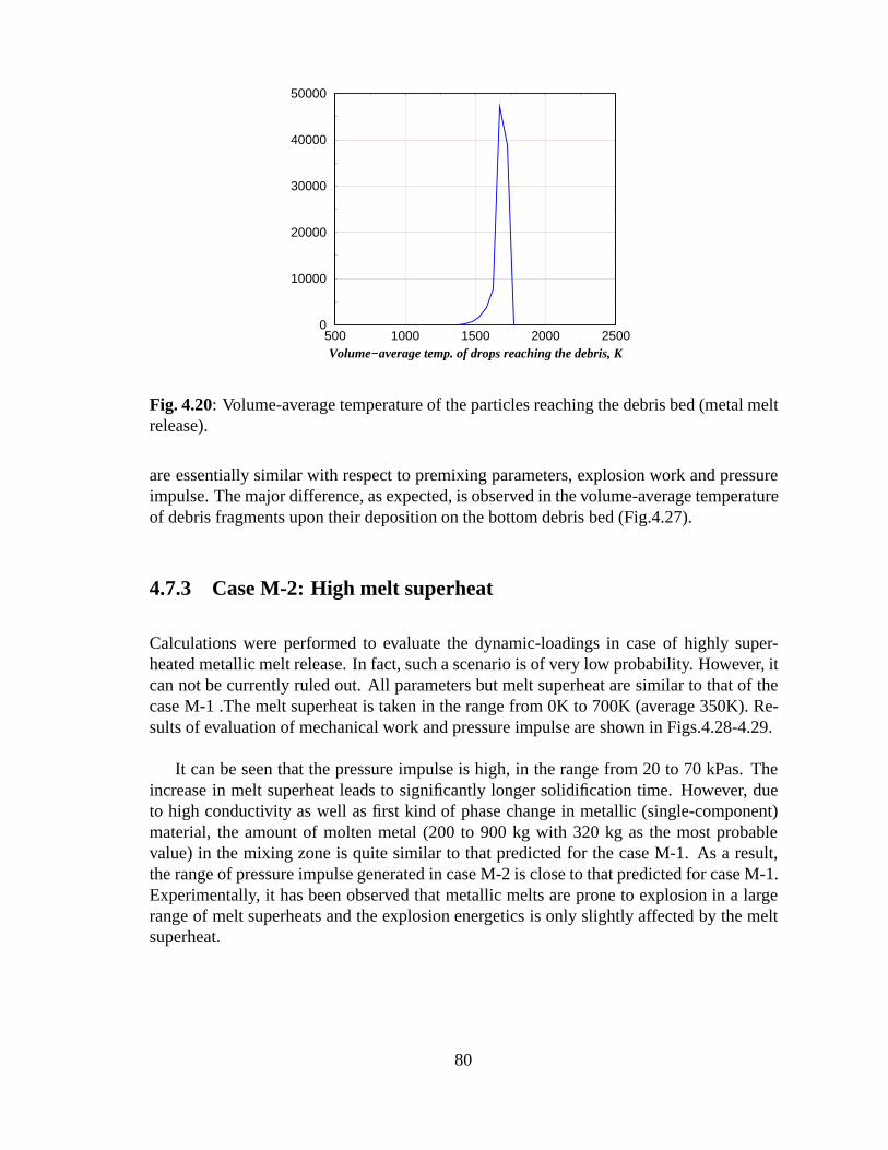
500 1000 1500 2000 2500Volume−average temp. of drops reaching the debris, K
0
10000
20000
30000
40000
50000
Fig. 4.20: Volume-average temperature of the particles reaching the debris bed (metal meltrelease).
are essentially similar with respect to premixing parameters, explosion work and pressureimpulse. The major difference, as expected, is observed in the volume-average temperatureof debris fragments upon their deposition on the bottom debris bed (Fig.4.27).
4.7.3 Case M-2: High melt superheat
Calculations were performed to evaluate the dynamic-loadings in case of highly super-heated metallic melt release. In fact, such a scenario is of very low probability. However, itcan not be currently ruled out. All parameters but melt superheat are similar to that of thecase M-1 .The melt superheat is taken in the range from 0K to 700K (average 350K). Re-sults of evaluation of mechanical work and pressure impulse are shown in Figs.4.28-4.29.
It can be seen that the pressure impulse is high, in the range from 20 to 70 kPas. Theincrease in melt superheat leads to significantly longer solidification time. However, dueto high conductivity as well as first kind of phase change in metallic (single-component)material, the amount of molten metal (200 to 900 kg with 320 kg as the most probablevalue) in the mixing zone is quite similar to that predicted for the case M-1. As a result,the range of pressure impulse generated in case M-2 is close to that predicted for case M-1.Experimentally, it has been observed that metallic melts are prone to explosion in a largerange of melt superheats and the explosion energetics is only slightly affected by the meltsuperheat.
80
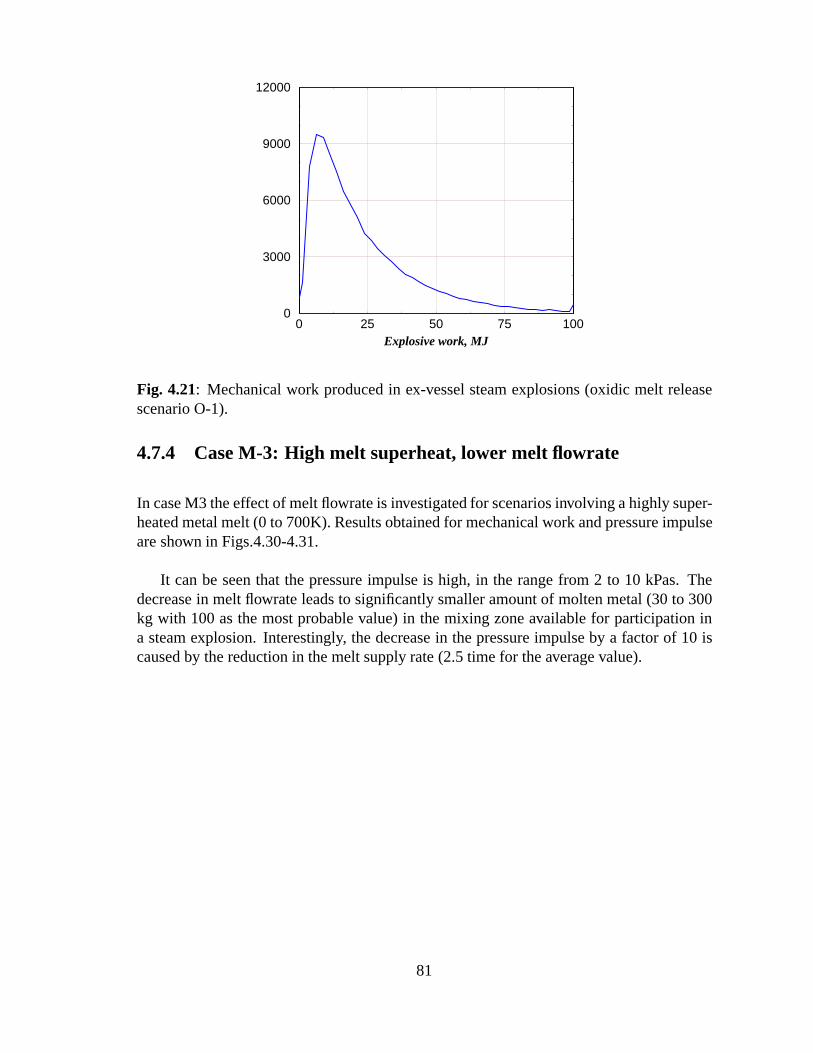
0 25 50 75 100Explosive work, MJ
0
3000
6000
9000
12000
Fig. 4.21: Mechanical work produced in ex-vessel steam explosions (oxidic melt releasescenario O-1).
4.7.4 Case M-3: High melt superheat, lower melt flowrate
In case M3 the effect of melt flowrate is investigated for scenarios involving a highly super-heated metal melt (0 to 700K). Results obtained for mechanical work and pressure impulseare shown in Figs.4.30-4.31.
It can be seen that the pressure impulse is high, in the range from 2 to 10 kPas. Thedecrease in melt flowrate leads to significantly smaller amount of molten metal (30 to 300kg with 100 as the most probable value) in the mixing zone available for participation ina steam explosion. Interestingly, the decrease in the pressure impulse by a factor of 10 iscaused by the reduction in the melt supply rate (2.5 time for the average value).
81
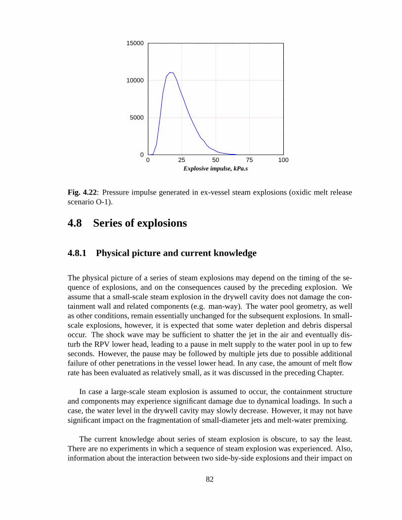
0 25 50 75 100Explosive impulse, kPa.s
0
5000
10000
15000
Fig. 4.22: Pressure impulse generated in ex-vessel steam explosions (oxidic melt releasescenario O-1).
4.8 Series of explosions
4.8.1 Physical picture and current knowledge
The physical picture of a series of steam explosions may depend on the timing of the se-quence of explosions, and on the consequences caused by the preceding explosion. Weassume that a small-scale steam explosion in the drywell cavity does not damage the con-tainment wall and related components (e.g. man-way). The water pool geometry, as wellas other conditions, remain essentially unchanged for the subsequent explosions. In small-scale explosions, however, it is expected that some water depletion and debris dispersaloccur. The shock wave may be sufficient to shatter the jet in the air and eventually dis-turb the RPV lower head, leading to a pause in melt supply to the water pool in up to fewseconds. However, the pause may be followed by multiple jets due to possible additionalfailure of other penetrations in the vessel lower head. In any case, the amount of melt flowrate has been evaluated as relatively small, as it was discussed in the preceding Chapter.
In case a large-scale steam explosion is assumed to occur, the containment structureand components may experience significant damage due to dynamical loadings. In such acase, the water level in the drywell cavity may slowly decrease. However, it may not havesignificant impact on the fragmentation of small-diameter jets and melt-water premixing.
The current knowledge about series of steam explosion is obscure, to say the least.There are no experiments in which a sequence of steam explosion was experienced. Also,information about the interaction between two side-by-side explosions and their impact on
82
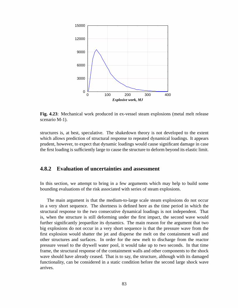
0 100 200 300 400Explosive work, MJ
0
3000
6000
9000
12000
15000
Fig. 4.23: Mechanical work produced in ex-vessel steam explosions (metal melt releasescenario M-1).
structures is, at best, speculative. The shakedown theory is not developed to the extentwhich allows prediction of structural response to repeated dynamical loadings. It appearsprudent, however, to expect that dynamic loadings would cause significant damage in casethe first loading is sufficiently large to cause the structure to deform beyond its elastic limit.
4.8.2 Evaluation of uncertainties and assessment
In this section, we attempt to bring in a few arguments which may help to build somebounding evaluations of the risk associated with series of steam explosions.
The main argument is that the medium-to-large scale steam explosions do not occurin a very short sequence. The shortness is defined here as the time period in which thestructural response to the two consecutive dynamical loadings is not independent. Thatis, when the structure is still deforming under the first impact, the second wave wouldfurther significantly jeopardize its dynamics. The main reason for the argument that twobig explosions do not occur in a very short sequence is that the pressure wave from thefirst explosion would shatter the jet and disperse the melt on the containment wall andother structures and surfaces. In order for the new melt to discharge from the reactorpressure vessel to the drywell water pool, it would take up to two seconds. In that timeframe, the structural response of the containment walls and other components to the shockwave should have already ceased. That is to say, the structure, although with its damagedfunctionality, can be considered in a static condition before the second large shock wavearrives.
83
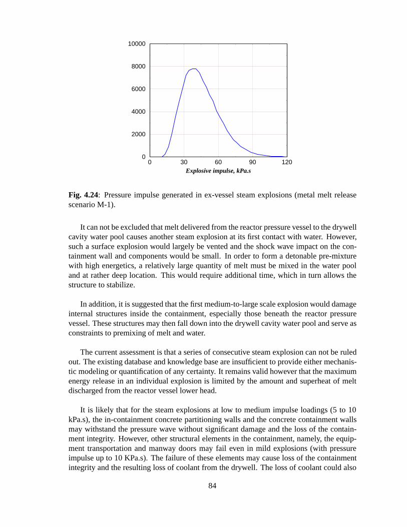
0 30 60 90 120Explosive impulse, kPa.s
0
2000
4000
6000
8000
10000
Fig. 4.24: Pressure impulse generated in ex-vessel steam explosions (metal melt releasescenario M-1).
It can not be excluded that melt delivered from the reactor pressure vessel to the drywellcavity water pool causes another steam explosion at its first contact with water. However,such a surface explosion would largely be vented and the shock wave impact on the con-tainment wall and components would be small. In order to form a detonable pre-mixturewith high energetics, a relatively large quantity of melt must be mixed in the water pooland at rather deep location. This would require additional time, which in turn allows thestructure to stabilize.
In addition, it is suggested that the first medium-to-large scale explosion would damageinternal structures inside the containment, especially those beneath the reactor pressurevessel. These structures may then fall down into the drywell cavity water pool and serve asconstraints to premixing of melt and water.
The current assessment is that a series of consecutive steam explosion can not be ruledout. The existing database and knowledge base are insufficient to provide either mechanis-tic modeling or quantification of any certainty. It remains valid however that the maximumenergy release in an individual explosion is limited by the amount and superheat of meltdischarged from the reactor vessel lower head.
It is likely that for the steam explosions at low to medium impulse loadings (5 to 10kPa.s), the in-containment concrete partitioning walls and the concrete containment wallsmay withstand the pressure wave without significant damage and the loss of the contain-ment integrity. However, other structural elements in the containment, namely, the equip-ment transportation and manway doors may fail even in mild explosions (with pressureimpulse up to 10 KPa.s). The failure of these elements may cause loss of the containmentintegrity and the resulting loss of coolant from the drywell. The loss of coolant could also
84
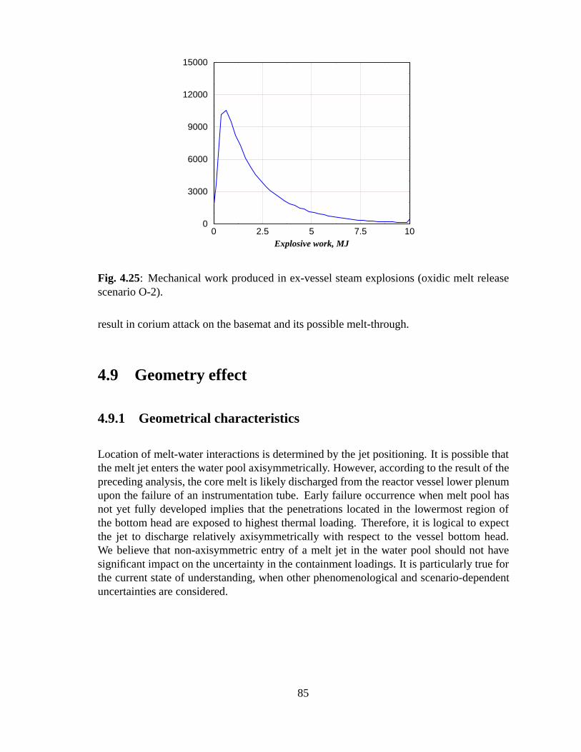
0 2.5 5 7.5 10Explosive work, MJ
0
3000
6000
9000
12000
15000
Fig. 4.25: Mechanical work produced in ex-vessel steam explosions (oxidic melt releasescenario O-2).
result in corium attack on the basemat and its possible melt-through.
4.9 Geometry effect
4.9.1 Geometrical characteristics
Location of melt-water interactions is determined by the jet positioning. It is possible thatthe melt jet enters the water pool axisymmetrically. However, according to the result of thepreceding analysis, the core melt is likely discharged from the reactor vessel lower plenumupon the failure of an instrumentation tube. Early failure occurrence when melt pool hasnot yet fully developed implies that the penetrations located in the lowermost region ofthe bottom head are exposed to highest thermal loading. Therefore, it is logical to expectthe jet to discharge relatively axisymmetrically with respect to the vessel bottom head.We believe that non-axisymmetric entry of a melt jet in the water pool should not havesignificant impact on the uncertainty in the containment loadings. It is particularly true forthe current state of understanding, when other phenomenological and scenario-dependentuncertainties are considered.
85
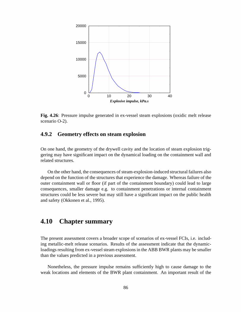
0 10 20 30 40Explosive impulse, kPa.s
0
5000
10000
15000
20000
Fig. 4.26: Pressure impulse generated in ex-vessel steam explosions (oxidic melt releasescenario O-2).
4.9.2 Geometry effects on steam explosion
On one hand, the geometry of the drywell cavity and the location of steam explosion trig-gering may have significant impact on the dynamical loading on the containment wall andrelated structures.
On the other hand, the consequences of steam-explosion-induced structural failures alsodepend on the function of the structures that experience the damage. Whereas failure of theouter containment wall or floor (if part of the containment boundary) could lead to largeconsequences, smaller damage e.g. to containment penetrations or internal containmentstructures could be less severe but may still have a significant impact on the public healthand safety (Okkonen et al., 1995).
4.10 Chapter summary
The present assessment covers a broader scope of scenarios of ex-vessel FCIs, i.e. includ-ing metallic-melt release scenarios. Results of the assessment indicate that the dynamic-loadings resulting from ex-vessel steam explosions in the ABB BWR plants may be smallerthan the values predicted in a previous assessment.
Nonetheless, the pressure impulse remains sufficiently high to cause damage to theweak locations and elements of the BWR plant containment. An important result of the
86
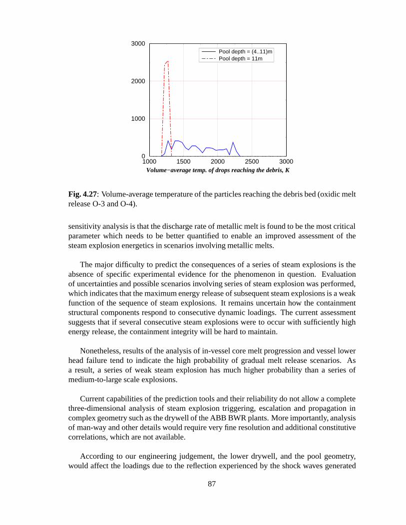
1000 1500 2000 2500 3000Volume−average temp. of drops reaching the debris, K
0
1000
2000
3000Pool depth = (4..11)mPool depth = 11m
Fig. 4.27: Volume-average temperature of the particles reaching the debris bed (oxidic meltrelease O-3 and O-4).
sensitivity analysis is that the discharge rate of metallic melt is found to be the most criticalparameter which needs to be better quantified to enable an improved assessment of thesteam explosion energetics in scenarios involving metallic melts.
The major difficulty to predict the consequences of a series of steam explosions is theabsence of specific experimental evidence for the phenomenon in question. Evaluationof uncertainties and possible scenarios involving series of steam explosion was performed,which indicates that the maximum energy release of subsequent steam explosions is a weakfunction of the sequence of steam explosions. It remains uncertain how the containmentstructural components respond to consecutive dynamic loadings. The current assessmentsuggests that if several consecutive steam explosions were to occur with sufficiently highenergy release, the containment integrity will be hard to maintain.
Nonetheless, results of the analysis of in-vessel core melt progression and vessel lowerhead failure tend to indicate the high probability of gradual melt release scenarios. Asa result, a series of weak steam explosion has much higher probability than a series ofmedium-to-large scale explosions.
Current capabilities of the prediction tools and their reliability do not allow a completethree-dimensional analysis of steam explosion triggering, escalation and propagation incomplex geometry such as the drywell of the ABB BWR plants. More importantly, analysisof man-way and other details would require very fine resolution and additional constitutivecorrelations, which are not available.
According to our engineering judgement, the lower drywell, and the pool geometry,would affect the loadings due to the reflection experienced by the shock waves generated
87

0 100 200 300 400Explosive work, MJ
0
3000
6000
9000
12000
15000
Fig. 4.28: Mechanical work produced in ex-vessel steam explosions (metal melt releasescenario M-2).
by the steam explosion.
4.11 References
H. Almstrom, T. Sundel, W. Frid and A. Engelbrektson, ”Significance of Fluid-StructureInteraction Phenomena for Containment Response to Ex-Vessel Steam Explosions” ,Proceedings of the OECD/CSNI Specialists Meeting on ”Fuel-Coolant Interactions” ,May 19-21, 1997, Tokai-Mura, Japan. NEA/CSNI/R(97)26, pp.120-144.
M. Baines and N.E Buttery , ”Differential Velocity Fragmentation in Liquid-Liquid Sys-tem” , Berkeley Nuclear Labs, RD/B/N 4643.
M. Berman , ”Light Water Reactor Safety Research Program Quarterly and Semi-annualReport” , Sandia National Laboratories Report, SAND84-2500, 1984.
M. J. Bird and R. A. Millington , ”Fuel Coolant Interaction Studies with Water andThermite-Generated Molten Uranium Dioxide” , 4th CSNI Spec. Mtg. on FCI inNuclear Reactor Safety, Bournemouth, UK, 1979.
M. J. Bird, ”An Experimental Study of Scaling in Core Melt/Water Interaction” , 22ndNational Heat Transfer Conference, Niagara Falls, 1984.
V.A. Bui, Phenomenological and mechanistic modeling of melt-structure-water interac-tions in a light water reactor (LWR) severe accident. Ph.D Thesis, RIT, 1998.
88
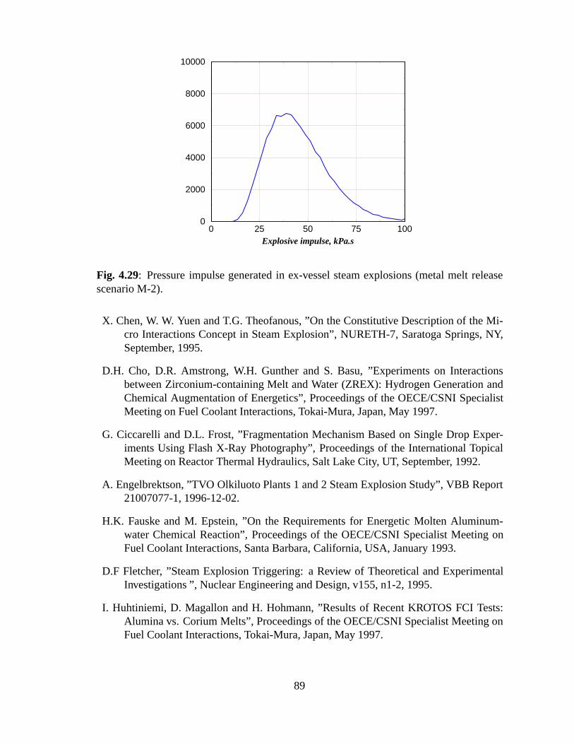
0 25 50 75 100Explosive impulse, kPa.s
0
2000
4000
6000
8000
10000
Fig. 4.29: Pressure impulse generated in ex-vessel steam explosions (metal melt releasescenario M-2).
X. Chen, W. W. Yuen and T.G. Theofanous, ”On the Constitutive Description of the Mi-cro Interactions Concept in Steam Explosion” , NURETH-7, Saratoga Springs, NY,September, 1995.
D.H. Cho, D.R. Amstrong, W.H. Gunther and S. Basu, ”Experiments on Interactionsbetween Zirconium-containing Melt and Water (ZREX): Hydrogen Generation andChemical Augmentation of Energetics” , Proceedings of the OECE/CSNI SpecialistMeeting on Fuel Coolant Interactions, Tokai-Mura, Japan, May 1997.
G. Ciccarelli and D.L. Frost, ”Fragmentation Mechanism Based on Single Drop Exper-iments Using Flash X-Ray Photography” , Proceedings of the International TopicalMeeting on Reactor Thermal Hydraulics, Salt Lake City, UT, September, 1992.
A. Engelbrektson, ”TVO Olkiluoto Plants 1 and 2 Steam Explosion Study” , VBB Report21007077-1, 1996-12-02.
H.K. Fauske and M. Epstein, ”On the Requirements for Energetic Molten Aluminum-water Chemical Reaction” , Proceedings of the OECE/CSNI Specialist Meeting onFuel Coolant Interactions, Santa Barbara, California, USA, January 1993.
D.F Fletcher, ”Steam Explosion Triggering: a Review of Theoretical and ExperimentalInvestigations ” , Nuclear Engineering and Design, v155, n1-2, 1995.
I. Huhtiniemi, D. Magallon and H. Hohmann, ”Results of Recent KROTOS FCI Tests:Alumina vs. Corium Melts” , Proceedings of the OECE/CSNI Specialist Meeting onFuel Coolant Interactions, Tokai-Mura, Japan, May 1997.
89
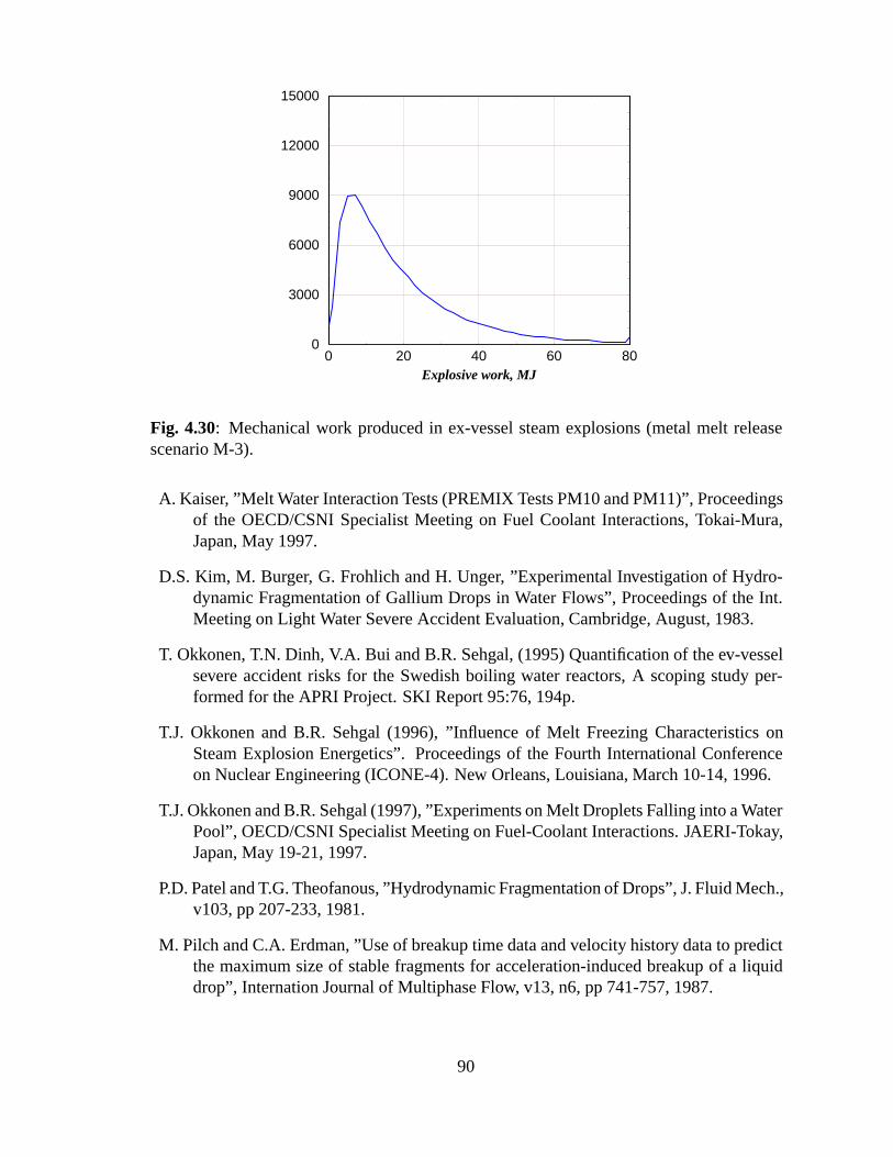
0 20 40 60 80Explosive work, MJ
0
3000
6000
9000
12000
15000
Fig. 4.30: Mechanical work produced in ex-vessel steam explosions (metal melt releasescenario M-3).
A. Kaiser, ”Melt Water Interaction Tests (PREMIX Tests PM10 and PM11)” , Proceedingsof the OECD/CSNI Specialist Meeting on Fuel Coolant Interactions, Tokai-Mura,Japan, May 1997.
D.S. Kim, M. Burger, G. Frohlich and H. Unger, ”Experimental Investigation of Hydro-dynamic Fragmentation of Gallium Drops in Water Flows” , Proceedings of the Int.Meeting on Light Water Severe Accident Evaluation, Cambridge, August, 1983.
T. Okkonen, T.N. Dinh, V.A. Bui and B.R. Sehgal, (1995) Quantification of the ev-vesselsevere accident risks for the Swedish boiling water reactors, A scoping study per-formed for the APRI Project. SKI Report 95:76, 194p.
T.J. Okkonen and B.R. Sehgal (1996), ” Influence of Melt Freezing Characteristics onSteam Explosion Energetics” . Proceedings of the Fourth International Conferenceon Nuclear Engineering (ICONE-4). New Orleans, Louisiana, March 10-14, 1996.
T.J. Okkonen and B.R. Sehgal (1997), ”Experiments on Melt Droplets Falling into a WaterPool” , OECD/CSNI Specialist Meeting on Fuel-Coolant Interactions. JAERI-Tokay,Japan, May 19-21, 1997.
P.D. Patel and T.G. Theofanous, ”Hydrodynamic Fragmentation of Drops” , J. Fluid Mech.,v103, pp 207-233, 1981.
M. Pilch and C.A. Erdman, ”Use of breakup time data and velocity history data to predictthe maximum size of stable fragments for acceleration-induced breakup of a liquiddrop” , Internation Journal of Multiphase Flow, v13, n6, pp 741-757, 1987.
90
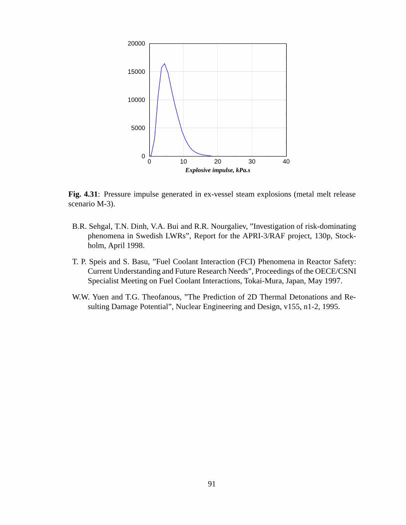
0 10 20 30 40Explosive impulse, kPa.s
0
5000
10000
15000
20000
Fig. 4.31: Pressure impulse generated in ex-vessel steam explosions (metal melt releasescenario M-3).
B.R. Sehgal, T.N. Dinh, V.A. Bui and R.R. Nourgaliev, ” Investigation of risk-dominatingphenomena in Swedish LWRs” , Report for the APRI-3/RAF project, 130p, Stock-holm, April 1998.
T. P. Speis and S. Basu, ”Fuel Coolant Interaction (FCI) Phenomena in Reactor Safety:Current Understanding and Future Research Needs” , Proceedings of the OECE/CSNISpecialist Meeting on Fuel Coolant Interactions, Tokai-Mura, Japan, May 1997.
W.W. Yuen and T.G. Theofanous, ”The Prediction of 2D Thermal Detonations and Re-sulting Damage Potential” , Nuclear Engineering and Design, v155, n1-2, 1995.
91
Chapter 5
Task 4: Remaining uncertainties andfuture work
5.1 Chapter objectives and approach
The objective of this Chapter is to discuss the remaining uncertainties and their impact onresults of the above assessments. The approach attempted is to go through the three criticalsevere accident phenomena, namely (i) the vessel failure mode and timing, and conditionsof melt discharge, (ii) molten fuel-coolant interactions, and (iii) debris coolability. Also,directions for future work are highlighted, and benefits are discussed.
5.2 Melt-vessel interactions and melt discharge conditions
In the case of a core melt accident, release of the melt from RPV (reactor pressure vessel)under moderate pressure of the primary system (less than 20 bars) could generate a moreor less dispersed melt which might be transferred by the blowdown process to the reactorcavity, the reactor compartments, and the containment. The melt dispersion will dependmainly on the geometry of the lower containment, the RPV failure mode and the residualpressure of the primary circuit. Recent experiments have shown that under certain condi-tions large fractions of the melt were expelled from the reactor cavity. Additional, morecomplete and systematic information is needed to quantify the dispersion process and tocontrol the consequences, e.g. by a certain geometry of the cavity or a further reduction ofthe residual pressure in the primary circuit.
Currently, there are two research projects supported by EC’s 5th Framework Programme,they are ARVI (Assessment of Reactor Vessel Integrity) and ECOSTAR (Ex-vessel coremelt stabilization research) projects. In both projects, the pressure vessel failure mode and
92
melt dispersion behavior from RPV will be investigated. We believe that these studies willhelp to reduce significant uncertainties in determining the vessel failure modes, timing,composition, quantity and superheat of oxidic and metallic melts available for dischargefrom RPV upon its failure.
5.3 Molten fuel-coolant interactions
With respect to triggerability and explosivity of corium melts, it is believed that related un-certainties (effect of physical properties, scale effects) can not be resolved easily and settledin a short time frame, despite the remarkable international efforts. Engineering judgementas well as reasonable conservatism should still be employed, while complemented by mech-anistic methods.
Nonetheless, for the purpose of reactor assessment, the following should be empha-sized. Although phenomenological uncertainties in quantifying parameters of molten fuel-coolant premixing and steam explosion triggering and propagation remain significant, thelargest uncertainties in the reactor assessment are related to the prediction of vessel meltsource for ex-vessel FCIs. These uncertainties are dictated by the lack of data and knowl-edge base necessary to verify the quantification. While series of steam explosion can not beruled out, their impact on the containment response, especially, access lock, is largely un-known. Behavior of the damaged structure (breakdown resistance) is believed to be largelynon-linear and deserves more attention and analysis, should the issue of series of steamexplosion be proven as risk-dominant.
Uncertainties in the FCI assessment are also related to the melt delivery configuration,such as multiple jet scenarios, which were found to be more prone to triggering and explo-sion (PREMIX-11 test).
5.4 Debris coolability
Even in case of no steam explosions, debris coolability remains a safety issue for the ABB-ATom BWR plants. However, it is believed that for the TVO plants, whose reactor con-tainments are situated on the clay rock, consequences of debris (un)coolability are limited.The highly subcooled and deep water pool contribute to the melt jet fragmentation and sub-sequent drop fine fragmentation and cooling, which also help to lengthen the time periodduring which the ex-vessel debris remains coolable and to limit the corresponding ablationof the concrete basemat. Again, the gradual melt release is the major limiting mechanism.
The effect of steam explosion on debris coolability is related mainly to the coolantlevel which is associated with the containment damage and coolant leakage behavior. Most
93
likely, small to mild steam explosions could cause such a deformation of the access lockthat some coolant leak occurs. Reinforcement of the access lock is therefore seen as ameasure to improve the containment performance both from the dynamic-loading point ofview and from the concrete basemat-meltthrough point of view.
5.5 Summary
In light of the current knowledge base, database and predictive capability of severe accidentassessment tools at different detail levels, it appears prudent to expect that no significantchanges in the uncertainty level could be achieved in a short, 2-3 years, time frame. Greaterconfidence level in the assessment could however be achieved by concentrating on relatedlimiting mechanisms, such as penetration failure and effect of physical properties of coremelt on the potential of an ex-vessel steam explosion.
94
Chapter 6
Concluding remarks
The present study is generally focussed on the review of ex-vessel steam explosion withparticular application for Swedish and Finnish BWR reactor containments during a hyper-thetical severe accident.
The state-of-art review shows that
(1) Though substantial progress had been made in premixing research verifying the mix-ing limit concept, and a number of premixing models and /or codes have been de-veloped and validated against these separate effect experiments, non of the codesperformed consistently well in post-test prediction of all measured quantities. Thecalculated energy release to the steam/water system was in general too low with re-spect to the experiment.
(2) The understanding of the triggering mechanisms is still poor. It has been observedthat a steam explosion may spontaneously trigger when the melt comes in contactwith structures, and may be artificially triggered by pressure waves induced by firinga small amount of explosive or by the rupture of a gas capsule. The prototypic coremelt has not shown a potential for a spontaneous explosion.
(3) It is believed that the material characteristics play a fundamental role in steam ex-plosion triggerability and explosivity, possibly explaining the low yield observed incorium tests. The role of non-condensable gases is poorly understood. In general,the kinetics of chemical interactions during the time-scale of the pre-mixing is notknown and, consequently, not modelled in the codes. Leaving aside the possible roleof chemical reactions during the propagation, non-condensable gases in the premix-ture are believed to make the triggering of an explosion more difficult and to limitthe energetics.
(4) Various analytical models have been developed based on the thermal detonation con-cept. However, the phenomenology of fine fragmentation of droplets and resulting
95
rapid heat transfer is believed to be not thoroughly understood for lack of extensiveappropriate experimental data involving prototypic core melt. Therefore, the needexists in both experimental and analytical research to understand better the dropletfragmentation during the explosion or propagation phase, to develop and/or improvefine fragmentation models, and to assess these models for reactor applications.
The evaluation of the steam explosion loads on the containment of the ABB BWR inthe event of core melt discharge, during a severe accident, into the pool established in thelower drywell has been performed. The study, however, is much broader in scope, sinceit addresses the events prior to core melt discharge, i.e. in vessel melt progression andthe modes of vessel failure, and the events after the occurrence of a steam explosion, i.e.,the dynamic loads on the containment structures and the coolability of the debris (melt)deposited on the containment basemat.
The study has reviewed the work performed earlier by the authors for the APRI Projects2 and 3, and the work performed by Prof. Theofanous evaluating the steam explosiondynamic loadings on the TVO BWR containment due to melt discharges in the pool, andthe work performed by VBB, a structural analysis organization, on the response of the TVOBWR containment to dynamic loadings.
The approach of the work performed in determining the dynamic loadings generatedby a steam explosion has been to identify mechanism which would limit the efficiency of asteam explosion e.g.:
� the melt conditions (superheat, composition)
� the melt discharge rate
� melt jet breakup/fragmentation
� melt freezing during the jet breakup/fragmentation process
� melt viscosity increases and mushy state effect on jet breakup and sequential frag-mentation
� melt composition effect on triggerability of a steam explosion and its explosivity.
It was found that several of the above mechanisms may limit the triggerability andexplosivity of prototypic, thereby reducing the steam explosion potential and its dynamicloads on the containment structures. The largest limiting contribution, perhaps, comes fromthe chosen range of melt discharge rate from the vessel to the pool. The choice is based onre-evaluating the containment failure scenario(s). The re-evaluation of the scenario and thevessel failure modes indicates that the most probable melt progression scenario leading toa vessel failure would be that of a dry core, in which the gradual melt addition to the lowerhead of a BWR leads to melt quenching.
96
The physical properties of the UO2-Zr-ZrO2 melt were found to be of significant helpin providing mechanisms to limit the steam explosion energetics. The large melt densitywas found to provide deeper sequential fragmentation of melt droplets leading to small sizeof melt droplets in the pre-mix zone. This in turn causes high local voiding and fast cool-down of the droplets and crust formation on their outer surface. The large change in themelt viscosity and surface tension of the melt droplet (mushy melt) hinders the extremelyfine fragmentation needed for generating a large-scale steam explosion.
The above mechanisms of melt drop freezing and the stiffness of the mushy melt are notas active for metallic melts as they are for binary oxide melt mixtures. Thus metallic meltsfor the same melt discharge rate may lead to larger scale steam explosions. There are notreliable experiments or models on the triggerability and explosivity of oxide melts mixedwith metallic melts at different proportions. Thus uncertainties in estimating the steamexplosion loads for prototypic BWR melt discharges into the containment water pool are,therefore, still quite large.
Other parameters and scenarios were assessed employing engineering judgement andprevious knowledge base. These include (a) occurrence of a series of consecutive steamexplosions, (b) multiple jet melt discharges, (c) non-axisymmetric melt jet discharges, (d)effects of pool water depth and (e) effects of a steam explosion on debris coolability. Ourconclusions about each of these are described in the following paragraphs.
(a) The probability of the occurrence of a series of consecutive steam explosions isjudged to be very low. The most probable scenario of melt discharge is judged to be throughpenetration failure, leading to small diameter jets, which would most probably be brokenup by the venting of preceding steam explosion close to the pool surface. There is no database available on either the occurrence of multiple consecutive steam explosions, or onthe effects on structures of multiple explosions. The effects probably are deterministic,however, the magnitude is not known. Data on the effects on structures may be availablefrom military research, unknown to the authors.
(b) Multiple jet discharges e.g. through more than one penetration tube failure scenariois considered likely. There is very little data on the increase or decrease of the probabilityof triggering or of the energetics of a steam explosion. One weak explosion was observedin the PREMIX tests, when melt was discharged in the form of three jets. Our judgementis that the energetics of explosions are primarily a function of the melt volume (mass) inthe pre-mix zone and of the spatial extent of the voiding (steam depletion). With multiplemelt jets, the mass of the melt in the pre-mixing zone may be larger, however, the voided(steam depletion) zone may also be large in spatial extent. Our engineering judgement isthat the effects of multiple jets may be small if any. However, there would be an increasein the magnitude of the uncertainty.
(c) Non-axisymmetric melt jet discharges were considered. In general, it is our judge-ment that for the vessel failure scenario, considered here to be most likely, the penetrationnear the middle of the vessel lower head will fail first and the melt jet discharge would, mostlikely, be axisymmetric. There is very little data on the energetics and on the structural
97
effects of non-axisymmetric steam explosions. Our judgement is that non-axisymmetricsteam explosions could have larger structural consequences because of greater proximityto the walls of the pool in the lower drywell.
(d) The effects of pool water depth on steam explosion energetics, and on structures,are, in general, increasing with the depth of the pool. Steam explosion in pools of depthless than 5 meters can, generally, be vented upwards. We find that beyond that depth theeffects saturate. In addition, for the scenario considered, the small diameter jets, generally,would have relatively short breakup length in the subcooled pool.
(e) Steam explosions could have a large effect on the subsequent coolability of thedebris bed formed, since they generate very fine particles in the melt droplet fragmentationprocess. These fine particles would be levitated during the explosion process and would,later on, settle down on the debris bed, or melt pool, created earlier in pool. Clearly lowporosity heat generating debris beds are much harder to cool with water overlayers. Otherscenarios in which a steam explosion may occur between melt discharges may lead to alow porosity debris layer sandwiched between higher porosity debris beds. In this instancealso debris coolability may become difficult. In general, we have found that even without asteam explosion, the debris bed formed (likely a melt pool covered by a debris bed), wouldbe 30 to 40 cm deep and, not easily coolable with a water overlayer.
The general conclusion of this study can be briefly summarized as:
� Though substantial progress have been made in premixing research verifying themixing limit concept, there is still a need to improve jet breakup models and validatethe existing models against melt jet experiments.
� The understanding of the triggering mechanisms is still very pool. Though variousanalytical models have been developed based on the thermal detonation concepts, theneed still exists in both experimental and analytical research to understand better thedroplet fragmentation during the explosion or propagation phase, to develop and/orimprove fine fragmentation models, and to assess these models for use in reactorapplications.
� The effects of a steam explosion of large or small yield on the debris coolability havebeen assessed, a low-porosity deep debris bed, which may be hard to cool, may begenerated.
� An engineering assessment of the steam explosion energetics has been performed.The assessment covers a broader scope of scenarios of ex-vessel FCIs, i.e. includingmetallic-melt release scenarios. Results of the assessment indicate that the dynamic-loadings resulting from ex-vessel steam explosions in the ABB BWR plants may besmaller than the values predicted in a previous assessment.
98