toxic gas monitoring system operation and maintenance forms... · ge proficy ifix software, ......
TRANSCRIPT

Doc. No. & Rev. EHS-00031 R21
Hard copy of this document, if not marked “CONTROLLED” in red, is by definition uncontrolled and may be out of date.
CNSE Confidential
Created by CNSE on June 26, 2015 Page 1 of 44
Procedure for
Toxic Gas Monitoring System Operation and Maintenance
REVISION
Rev No.
DCN No. Change Summary Release Date
DCN Initiator
Document Owner
21 DCN1215
Added criteria for maintenance mode usage; Update Facility terminology and contact info
7-21-15 Lilia Chen Tom Diamond
Prior revision history, if applicable, is available from the Document Control Office.
Toxic Gas Monitoring System Operation and Maintenance EHS-00031 R21
Printed copies are considered uncontrolled. Verify revision prior to use.
DCN1215 CNSE Confidential Page 2 of 44
1. PURPOSE AND SCOPE
1.1 To establish standard operating and maintenance procedures for the Toxic Gas Monitoring System (TGMS) that uses the following at SUNY Polytechnic Institute’s Colleges of Nanoscale Science and Engineering (CNSE) facility:
Gas sensors to monitor hazardous gases
Heat sensors to monitor flammable/explosive gases.
Pressure transducer to monitor exhaust flow.
1.2 This standard sets forth the procedures for:
1.2.1 Establishing alarm concentration and pressure levels.
1.2.2 Assigning points to a specific detector.
1.2.3 Addition and deletion of monitoring points to the TGMS.
1.3 This standard shall apply to:
1.3.1 All personnel within a designated alarm area when an alarm is activated,
1.3.2 All members of the Emergency Response Team on site,
1.3.3 All facility and tool maintenance support personnel on site responsible for installation and/or deletion of system components, “Authorized Personnel”, and
1.3.4 All Security personnel on site.
2. EXCEPTIONS
2.1.1 The VP of EHS may permit variations from the criteria set forth by this procedure, if equal or greater safety is provided.
3. DEFINITIONS
3.1 Hazardous gas: A gas (or mixture of gases) that is toxic, an irritant, corrosive, combustible, flammable, dangerously reactive, pyrophoric, or that otherwise may cause substantial acute or chronic personal injury or illness during, or as a direct result of, any customary or reasonably foreseeable handling or use.
3.2 Hazardous production area Any area that may reasonably be exposed to a hazardous gas and is continuously occupied by personnel in the normal performance of their job.

Toxic Gas Monitoring System Operation and Maintenance EHS-00031 R21
Printed copies are considered uncontrolled. Verify revision prior to use.
DCN1215 CNSE Confidential Page 3 of 44
3.3 Hazardous Production Material (HPM) Any material that presents a toxicity or safety risk to personnel in the area.
3.4 Permissible Exposure Limit (PEL) The Permissible Exposure Limit is the maximum permitted 8-hour time-weighted average concentration of an airborne contaminant established by the Occupational Safety and Health Administration (OSHA).
3.5 Threshold Limit Value (TLV) The Threshold Limit Value is an 8-hour time-weighted average concentration of a hazardous chemical that an average person may be exposed to day after day without any adverse effect. TLVs are guidelines established by the American Conference of Governmental Industrial Hygienists.
3.6 Lowest Alarm Level (LAL) If the warning set point is lower than the lowest concentration level that can be detected by the sensor the warning set point is set to lowest detectable concentration value.
3.7 Lower Explosive Limit (LEL) The minimum concentration of flammable gas or vapor mixed with air that can be ignited. LEL is typically expressed as a percent of flammable gas or vapor in air.
3.8 Warning Condition: Warning conditions have been set for both gas sensors and pressure transducers and either condition will activate and alarm.
3.8.1 Gas Sensors -The lowest concentration level that will set off an alarm. This concentration is referred as a WARNING and does NOT activate the room alarms. The concentration level should be no more than half the concentration level of the Alarm and when possible, the sample time should not exceed 30 seconds.
3.8.2 Pressure and Flow Transducers – One half (1/2) of the steady state (normal) reading is the warning set point. This condition will NOT activate the room alarms.
3.9 Authorized Personnel – The following personnel are authorized to make alterations, deletions or additions to the TGMS:
CNSE EHS Personnel
CNSE TGMS Services Personnel
CNSE Approved Contractors and their approved designees (sub-contractors)
Toxic Gas Monitoring System Operation and Maintenance EHS-00031 R21
Printed copies are considered uncontrolled. Verify revision prior to use.
DCN1215 CNSE Confidential Page 4 of 44
3.10 Alarm Condition
3.10.1 Gas Sensors – The higher concentration level of the two alarms. The concentration level must never exceed the TLV or 20% of the LEL for the monitored gas. This is referred as the ALARM level concentration and WILL activate the room alarms, signaling the need to evacuate the area.
3.10.2 Pressure Transducers –
Warning levels – Low: 75% of “Normal” Reading, High: 150% of “Normal” Reading
Alarm levels – Low: 50% of “Normal” Reading, High: 175% of “Normal” Reading
This condition will NOT activate the room alarms.
High Alarms are not specifically required by EHS and can be adjusted by authorized personnel to avoid nuisance alarms.
3.10.3 Exhaust Flow Transducers –
Warning levels – Low: 75% of “Normal” Reading
Alarm levels – Low: 50% of “Normal” Reading
This condition will NOT activate the room alarms.
High Flow Alarms are not required.
3.10.4 Heat Sensors - 150F is alarm set point for heat detectors. Temperature alarms will NOT set off room alarms.
3.11 Trouble Condition: Wire breaks and instrument failures are classified as trouble conditions. AAC (see Section 4.11) and Human Machine Interface (HMI) screens notify the operator of trouble conditions, but do NOT set off area alarms and horns.
3.11.1 Trouble Alarms will page to ERT. The AAC and the Human Machine Interface (HMI) screens will notify the operator and Security of the trouble condition(s) after 5 minutes of being in a fault condition. The gas not being monitored due to the fault condition will SHUT OFF after an additional 55 minutes, if the trouble alarm is not cleared. If the fault can be cleared within the given 55 minutes, there will be no impact on the gas and no effect on normal operations.
3.12 Toxic Gas Monitoring System (TGMS): TGMS monitors toxic gas and controls the use of toxic gasses in the CNSE Facility. TGMS also

Toxic Gas Monitoring System Operation and Maintenance EHS-00031 R21
Printed copies are considered uncontrolled. Verify revision prior to use.
DCN1215 CNSE Confidential Page 5 of 44
monitors exhaust flow and heat sensor to ensure safety of work area. When evacuation is required, TGMS sets off strobe lights and horns
3.13 Area Alarm Controller (AAC) AAC touch screens that display local status of fixed gas detectors, heat detectors and pressure transmitters that detect exhaust flow are connected to AAC. The CUB building, South Annex, South and North Lab, East building, Central Lab and Extension Lab area alarms and horns are controlled and monitored by the corresponding AACs, which send signals to the local PLC (Programmable Logic Control) located in communication hubs through Ethernet network, which sets off area alarms and horns.
3.14 Supervisory Control and Data Acquisition (SCADA) computer: A SCADA Computer communicates with the PLCs and AACs through an Ethernet network on a Fiber Optic Cable Network (Backbone). It also monitors the health of the network and displays alarm information and location. GE Proficy iFix software, that is utilized by the SCADA, provides interactive screens to display an overview of the facility, alarm locations and alarm status.
When any TGMS SCADA Screen is found to be NOT 100% functional - contact TGMS Services (TGMS Technicians at 518-620-6GAS or Ray Michael) or EHS (Thomas Diamond, Lilia Chen, and Jen Colavito) immediately and notify them of the situation via EMAIL. TGMS SCADA Screens are located in: NFN, NFC, NFE Security Control Center, NFS, NFSX and NFX.
3.15 Backbone (Fiber Optic Cable Network): The Backbone provides communication between all PLCs and the SCADA. The Fiber Optic network offers fast communication between the hubs in each location monitoring the AACs. The communication hubs contain an Ethernet Switch and Fiber Optic Expansion Modules to support connection between the local Ethernet network and Backbone.
4. ASSOCIATED DOCUMENTS
4.1 EHS-00031-F1: Gas Detector Point Monitoring Request Form
4.2 EHS-00031-F2: Hazardous Gas Monitoring Process Checklist Sign-Off Form
4.3 EHS-00031-F3: Inputs and Outputs Matrix
4.4 EHS-00031-F4: Monitoring Device Calibration Checklist
4.5 EHS-00031-F5: Strobe Lights and Horns Test Checklist
4.6 EHS-00031-F6: Heat Detector Condition Test Checklist
4.7 EHS-00031-F7: Pressure Transducer Condition Test Checklist

Toxic Gas Monitoring System Operation and Maintenance EHS-00031 R21
Printed copies are considered uncontrolled. Verify revision prior to use.
DCN1215 CNSE Confidential Page 6 of 44
4.8 EHS-00031-F8: Gas Detector Condition Test Checklist
4.9 EHS-00031-F9: Maintenance Mode Warning Sign
4.10 EHS-00031-F10: TGMS Testing Sign Location Checklists
4.11 EHS-00031-F11: TGMS Testing Checklist
4.12 EHS-00031-F12: TGMS Tool Signal Worksheet
4.13 EHS-00031- R1: TGMS Approved Gas Detection Table Reference
4.14 EHS-00031-T1: TGMS Testing NOTICE Template
4.15 CFM-00008-F1: TGMS Modification Sub-Permit (Work Permit)
5. TOXIC GAS MONITORING SYSTEM (TGMS)
5.1 All contractors installing TGMS components at the CNSE facility should use Section 6.0 through Section 17.0 to ensure all components are installed in accordance with criteria set forth by CNSE EHS department.
5.2 The TGMS monitors and controls the use of toxic gases in the CNSE Facility and its control system is composed of several interdependent pieces of hardware.
Area Alarm Controller (AAC)
Supervisory Control and Data Acquisition (SCADA)
5.3 AAC panels provide local monitoring and protection on a continuous basis. They distribute this information via the facility’s Ethernet communications system and a central alarm PLC in the CUB, South Annex, South and North Lab.
5.4 Gas level monitoring is performed by gas monitoring sensors, installed at gas usage points, pressure and air flow sensors are used to detect low airflow conditions, and heat sensors are monitored to alarm on high temperatures. The detectors/sensors are connected to the AAC panels which are used to supervise several sensors at each tool location.
5.5 Each AAC is provided with a local status display and alarm strobe to provide local indication of status and alarm conditions on a continuous basis.
5.6 The SCADA Servers are located in NFN and have information transmitted from the Ethernet communication system through a Fiber optic network backbone.

Toxic Gas Monitoring System Operation and Maintenance EHS-00031 R21
Printed copies are considered uncontrolled. Verify revision prior to use.
DCN1215 CNSE Confidential Page 7 of 44
6. TGMS AAC PANEL AS-BUILT DRAWINGS
All new and/or changes/edits to any AAC panels are required to have the complete, up-to-date as-built drawings installed within the AAC panel itself no later than two (2) weeks after EHS/TGMS Services has signed off on TGMS testing.
Also a complete, up-to-date copy of the drawings sent to the TGMS Services department either via email or CD copy.
7. AREA ALARM CONTROL PANEL
7.1 The AAC panels are connected to a facility wide Ethernet communications system. This system ties the monitored areas together to allow monitoring of all areas. Central alarm management PLCs that are located in NFN, NFC, NFS, NFSX and NFE communication hub enclosures, provide control for cleanroom and lab evacuation alarm lights and horns. Whereas, evacuation alarm lights and horns for the CUB, HPM Warehouse, Purification Building, NFN Purification Room, NFN HPM Corridor and NFC HPM Corridor are controlled by the AAC systems in those areas.
7.2 All AAC HMI screens, including remote monitoring screens, are required to have memory cards installed and contain a backup of the installed program for the screen.
7.3 The AAC interfaces with tools, gas cabinets and Valve Manifold Boxes (VMB) in the local area. The AAC receives ‘ready’ signals from gas cabinets and VMBs when gas bottles are installed and ready for operation. One the AAC received the ‘ready’ signal; it enables the tool/process modules and opens the gas valves when tool/process modules request gas. AAC panels do not receive or transmit a ‘ready’ signal if an alarm condition exists.
7.4 TGMS Evacuation Buttons will activate the evacuation (blue) lights for the zone they are located in. They do not shutdown any facilities. The TGMS Evacuation Button will be tested and verified twice yearly during the planned shutdowns.
7.5 TGMS Shutdown Buttons, associated with gas cabinets, shuts down all gas valves in the cabinets. The TGMS Shutdown Button will be tested and verified twice yearly during the planned shutdowns.
7.6 Each tool has an Emergency Manual Off (EMO) that is monitored by TGMS EMO Status signals. These signals are then broadcasted to the AAC panels. When the AAC receives a Tool EMO signal, the AAC closes the valves and disables gas request signals to the corresponding gas cabinets and VMBs.
Toxic Gas Monitoring System Operation and Maintenance EHS-00031 R21
Printed copies are considered uncontrolled. Verify revision prior to use.
DCN1215 CNSE Confidential Page 8 of 44
8. SUPERVISORY CONTROL AND DATA ACQUISITION (SCADA) COMPUTER
A distributed computer system provides cleanroom wide monitoring for all AAC’s and alarm management units. This system is composed of computers running SCADA software (GE Proficy iFix). These computers communicate via the Ethernet network to all of the AAC units and with each other.
When any TGMS SCADA Screen is found to be NOT 100% functional - contact TGMS Services (TGMS Technicians at 518-620-6GAS or Ray Michael) or EHS (Thomas Diamond, Lilia Chen, and Jen Colavito) immediately and notify them of the situation via EMAIL. TGMS SCADA Screens are located in: NFN, NFC, NFS, NFSX and NFX.
8.1 Locations
8.1.1 Main monitoring computer is located in the NFE building Rotunda. From this SCADA Computer, alarms can be viewed, logged, and printed out if detail trends are required for analysis.
8.1.2 Remote monitoring nodes are located in the South building at the rear entry door area to the main hallway; also one in the rear entrance area to the South Annex. Two remote monitoring nodes are located in NFN building – one in NFN Fab level pass through, and one in Sub Fab level pass through area. Three are located in NFC, one near the Sub Fab pass through area, and one in the Fab gowning room, and the third is located near the ERT closet on the Fab level. If an alarm, warning or trouble condition is detected, the AAC status information will be displayed on the computer screens. These remote screens allow ERT personnel to view current conditions in the lab, to acknowledge alarms, and to examine historical trend logs of monitored values. The computer systems and remote screens are password protected to prevent unauthorized personnel from gaining access to the system.
8.2 Screens
8.2.1 The ‘Screen Header Bar’ shows the current screen title, the user logged on, and the current time and date. The screen footer section shows the most recent alarms, and displays navigation buttons to select different screens.
8.2.2 The ‘Main Overview’ screen shows an overview of the facility. Monitored areas are animated based on the status condition in their area. If the area is blinking this indicates that active alarms in the area have not been acknowledged. A solid color area indicates that an alarm in the area has been acknowledged.

Toxic Gas Monitoring System Operation and Maintenance EHS-00031 R21
Printed copies are considered uncontrolled. Verify revision prior to use.
DCN1215 CNSE Confidential Page 9 of 44
8.2.3 The SCADA view nodes show the AAC locations and status of the AAC.
8.2.4 The ‘Alarm Summary’ screen displays all of the alarms that are currently present in the system. The “Acknowledge All” button allows the operator to acknowledge all alarms that are currently present. The Alarm History screen displays a list of cleared alarms.
8.2.5 The AAC ‘Detailed Information’ screens show the analog sensor and digital devices connected to the AAC, the current reading, alarm set points and warning set points.
8.2.6 Historical trends are available for any of the sensor points by clicking the sensor point name in the ‘Detailed Information’ screen.
8.2.7 Alarm, warning, and trouble conditions are indicated on screens by blinking a section, or sections, of the screen. The condition will continue to blink until the alarm has been acknowledged; once the condition has been acknowledged; the section will stop blinking and be displayed as a solid color until the condition is cleared. The following are the colors that are associated with a particular condition:
Alarm – Red
Warning – Yellow
Wire break – Cyan
Trouble – Magenta
Maintenance – Blue
Unacknowledged at Tool AAC – Pink
Communication Failure to AAC - Orange
9. TGMS TESTING
9.1 The following list of Forms and Appendices should be reviewed:
See EHS-00031- EHS-00031-F11: TGMS Testing Checklist prior to all TGMS testing being scheduled and coordinated.
See EHS-00031-F10: TGMS Testing Sign Location Checklists.
See EHS-00031-T1: TGMS Testing NOTICE Template.
See Appendix A: TGMS Text Guideline for AAC, SCADA, and Paging System / ACC Display Definitions.

Toxic Gas Monitoring System Operation and Maintenance EHS-00031 R21
Printed copies are considered uncontrolled. Verify revision prior to use.
DCN1215 CNSE Confidential Page 10 of 44
See Appendix B: TGMS Testing Verification.
All equipment must be tested and verified per the Matrix prior to an “official” TGMS test with TGMS Services. A pre-tested TGMS Matrix must be completed, signed (by IC, EE and TGMS Contractor), and submitted to CNSE prior to “official” TGMS testing.
If a tool or piece of equipment is modified in ANY way that impacts the interface to the TGMS, the connected AAC will be required to have a complete TGMS test performed to verify proper operation.
9.2 Blue Light Bypass and Blue Light Zones – all needs to be confirmed prior to testing by coordinator.
BLUE LIGHT Testing
Blue Light Zones Locations to Evacuate Blue Light Bypass
NFN NFN FAB, NFN Sub-FAB, NFN HPM corridor, Analytical rooms (CNM14, CNM27, CNM44, CNE04), NFC FAB, NFC Sub-Fab, Purification Room
NFN/NFC Switch Blue Light Bypass Includes All
NFC NFN FAB, NFN Sub-FAB, NFC HPM corridor, Analytical rooms, NFC FAB, NFC Sub-Fab, Purification Room
NFN/NFC Switch Blue Light Bypass Includes All
Analytical Room(s) NFN FAB, NFN Sub-FAB, NFN HPM corridor, Analytical room(s), NFC FAB, NFC Sub-Fab, Purification Room
NFN/NFC Switch Blue Light Bypass Includes All
NFN Purification Room NFN Purification Room No Blue Light Bypass
NFS NFS FAB, NFSX FAB NFS/NFSX Switch Blue Light Bypass Includes All
NFSX NFS FAB, NFSX FAB NFS/NFSX Switch Blue Light Bypass Includes All
CUB CUB No Blue Light Bypass
NFE Lab 1903 1903 Lab ONLY No Blue Light Bypass
NFE Lab 1904 1904 Lab ONLY No Blue Light Bypass
Purification Building Purification Building No Blue Light Bypass
NFN HPM Corridor NFN HPM corridor No Blue Light Bypass
NFC HPM Corridor NFC HPM corridor No Blue Light Bypass
HPM Building HPM Building No Blue Light Bypass
CESTM CESTM L233 room ONLY No Blue Light Bypass
PHYSICS LAB Physics Lab No Blue Light Bypass

Toxic Gas Monitoring System Operation and Maintenance EHS-00031 R21
Printed copies are considered uncontrolled. Verify revision prior to use.
DCN1215 CNSE Confidential Page 11 of 44
9.3 TGMS Testing Procedure
TGMS testing is allowed M-F during normal business hours if TGMS BLUE LIGHT BYPASS IS ACTIVE and TGMS Services/ERT/EHS member is monitoring TGMS system during entire TGMS test. If an addition to BLUE LIGHT system (i.e. Adding a new light) is needed to test, testing will be allowable ONLY before 8:00 AM or After 5:00 PM Monday through Thursday.
Exceptions: Any NON BLUE Light test (Heat, Liquid Leak, Pressure, Tool Interlocks, etc.) can be performed with TGMS Services as a witness Monday through Friday during normal business hours.
HIGHLY TOXIC materials and pyrophorics that exceed a ½ IDLH level at exhaust outlet are required to be tied into our house management system and ramp up exhaust to 100% upon a gas detection alarm. CNSE staff will determine if ½ IDLH level is exceeded in a catastrophic release. All testing of related gas detectors for catastrophic releases will need to be coordinated with Cleanroom Management, TGMS Services and EHS prior to commencement of such testing. (Please contact TGMS Services/EHS for clarification).
All gas cabinets and VMB’s in the HPM Corridors/Areas are required to be tied into the TGMS “SHUTDOWN” buttons outside the given areas. The TGMS Shutdown buttons will be tested during the planned shutdowns by TGMS Services.
Local alarms are tool specific alarms and do NOT set off room alarms. Conditions that set off local alarms must be cleared by tool maintenance support personnel, tool owners or their designees. Typically local alarms also flash or appear on the AAC HMI screens. A gas alarm is considered to be a global alarm condition and will set off room alarms, signaling that an evacuation is required.
The following are classified as Local Alarm Conditions:
Heat Sensor alarms (also sends out a page),
Pressure Transmitter alarms,
Wire Breaks (also sends out a page),
Trouble Alarms (also sends out a page),
o Trouble Alarms will page to ERTs. The AAC and the Human Machine Interface (HMI) screens will notify the operator and Security of the trouble condition(s) after 5 minutes of being in a fault condition. The gas not being monitored due to the fault condition will SHUT OFF after an additional 55 minutes,
Toxic Gas Monitoring System Operation and Maintenance EHS-00031 R21
Printed copies are considered uncontrolled. Verify revision prior to use.
DCN1215 CNSE Confidential Page 12 of 44
if the Trouble Alarm is not cleared. If the fault can be cleared within the given 55 minutes, there will be no impact on the gas and no effect on normal operations.
- Page ERT 5 minute all “faults”/”trouble”
- Show “countdown” for 55 minute gas SHUT OFF on AAC and Remote AAC TGMS screens as well as SCADA screens.
- Shut off gas and/or gases that is not being monitored after 55 minute countdown is complete.
Onboard fire detection or suppression or ‘fire alarm’ (also sends out a page), TGMS connection is secondary. Primary connection is to house fire alarm system and is covered by fire system specification documents. Stand-alone Dual IR sensors are handled in TGMS only.
Onboard leak detection (also sends out a page) and/or
Tool EMO or shutdown (also sends out a page).
The following are classified as Global Alarm (TGMS Alarm) Conditions:
Gas Sensor alarms (also sends out a page),
House Exhaust Pressure alarms (in CUB only), and/or
Dual I/R Fire Alarms (in HPM areas only).
10. SYSTEM BACK UP
TGMS server system is to be set up so that it is entirely backed up weekly. (Will be controlled and maintained by TGMS Services).
11. FIXED GAS DETECTION
The following is a listing of the fixed gas detection devices that have been installed at the CNSE facility.
(Honeywell is preferred for all gas detection monitoring.)
Honeywell Satellite 4-20 mA/R Toxic Gas Transmitters
Honeywell Satellite 4-20 mA/R Pyrolyzer Transmitters
Honeywell CM4 (Low Level AsH3)
Honeywell Midas Extractive Units
Toxic Gas Monitoring System Operation and Maintenance EHS-00031 R21
Printed copies are considered uncontrolled. Verify revision prior to use.
DCN1215 CNSE Confidential Page 13 of 44
Honeywell ACM-100 FTIR (CNSE Approved Applications ONLY)
Honeywell Optima (CH4 sensor for IPA Sensing ONLY)
RKI Instruments Riken Highly Sensitive Toxic Gas Monitor – FP260AGZS
DOD Instruments/COSMOS Electric PS-7
11.1 The bulk of the Toxic Gas transmitters at CNSE use electrochemical gas sensors that detect target gases through a series of electrochemical reactions. Detected gas concentration is converted to 4-20mA signal and wired to the AAC. Each Toxic Gas transmitter is set up to be used for the detection of a specific target gas.
11.2 For ALL CO gas detection a Midas gas detection unit provided by Honeywell is required due to cross interference on other units.
11.3 NOTE: During all Hydrogen BULK GAS Deliveries – all SiH4 TGMS sensor “TROUBLE” alarms are to be ignored during entire H2 delivery ONLY. If SiH4 TGMS trouble alarm is still in “trouble” condition after H2 delivery Security must contact ERT members to respond as normal.
CNSE Security team to send ERT page before H2 delivery to ignore all SiH4 TGMS TROUBLE alarms during entire H2 delivery:
“PLEASE IGNORE ALL SiH4 TGMS TROUBLE ALARMS until FURTHER NOTICE as H2 DELIVERY is in progress”
Once H2 delivery is 100% complete Security team to send ERT page to treat all SiH4 TGMS TROUBLE alarms as normal
“H2 delivery is 100% complete, please treat all SiH4 TGMS trouble alarms as NORMAL”
SiH4 SCOTT Sensors give a NEGATIVE RESPONSE during H2 delivery and SiH4 sensors go into “trouble” alarm during delivery (especially CUB)
11.4 For Flourinated compounds that cannot be detected by electrochemical gas sensors directly, pyrolyzers are used to heat the F2 to transform it to a species that can be detected electrochemically.
11.5 An NF3 pyrolyzer is used only for NF3 gas monitoring. NF3 MST pyrolyzer should be fitted with a charcoal filter due to cross sensitivity with Fluorinated compounds like Fluorinert and Galden fluids.
11.6 C4F6 pyrolyzer is used only for C4F6 gas monitoring. C5F8 pyrolyzer is used only for C5F8 gas monitoring. Honeywell Satellite XT with Pyrolyzer for C5F8 monitoring requires an extractive pump calibrated to 350cc/min (0.35 lpm) flow. (NOTE: All pyrolyzer units are tested before sign-off for “fault” alarms).

Toxic Gas Monitoring System Operation and Maintenance EHS-00031 R21
Printed copies are considered uncontrolled. Verify revision prior to use.
DCN1215 CNSE Confidential Page 14 of 44
11.7 For detection of C4F6 and C5F8 a Riken tape unit has been utilized. The Riken tape is based on a colorimetric change and once the change is detected the reading is transmitted to the AAC panel which displays the concentration in part per million (ppm).
11.8 Per New York State Fire Code a minimum of three (3) detection points are required for monitoring a specific piece of equipment and shall be located as follows:
The exhaust of a piece of specific equipment that utilizes a hazardous production material (exhaust).
The gas cabinet or valve manifold box where the gas is stored (exhaust).
The hazardous production area where the equipment or pump packages are used (ambient). A sensor can only monitor on one floor (i.e. a sensor on the Fab level cannot monitor on the Sub-fab level).
If applicable, the generator (ozone or hydrogen) where the gas is produced (exhaust).
11.9 Tool gas cabinets, storage gas cabinets, gas generators and VMBs will have TGMS detector points located in the exhaust connection to each device.
11.9.1 Exhausted enclosures (such as those found in tool gas boxes and GIBs) will be monitored with TGMS points for each specific gas located within the exhausted enclosure.
11.9.2 Combining gas detection into a single point along an exhaust duct (several gas boxes feeding into a common duct) is allowed, provided it can be demonstrated that it meets the code requirement of detecting a leak at the PEL level in the single gas box would still be detected. In order to take advantage of combining detection requirements onto a single detector point calculations showing exhaust dilution rates will need to be supplied to EHS.
11.10 The hazardous production area where the equipment is maintained (Ambient). This requirement will be met by ambient monitoring around chambers or load locks downstream from the air flow pattern.
This may be at the cleanroom level, below the raised floor or just below the waffle slab. Exact location to be determined by tool configuration and air flow pattern studies that will be carried out around the tool.

Toxic Gas Monitoring System Operation and Maintenance EHS-00031 R21
Printed copies are considered uncontrolled. Verify revision prior to use.
DCN1215 CNSE Confidential Page 15 of 44
In the sub-Fab this requirement will be met by monitoring around pump packages and abatement units at a height of 5’ in the ambient air.
Therefore it is anticipated that there will be two ambient points per gas type per tool.
11.11 TGMS detection is not required in pump exhaust, pump skin exhaust or
point -of-use abatement unit process exhausts. Ambient gas detection is utilized in the area of pumps and abatement units instead. Locations to be approved by EHS.
11.12 Gas detectors should be installed at least 5 duct diameters downstream from a gas cabinet vent line.
11.13 Gas detectors should be positioned before the blast gate. If combined gas detection is desired for multiple exhaust ducts, EHS will approve application after receipt of applicable dilution calculations.
11.14 If the hazardous production area is being monitored, and an additional process module using a gas from the same gas family is installed in close proximity to the original process modules, the original monitoring point for the production area may be relocated in such a way as to monitor the load stations of both modules. In this case, the new module would need only two monitoring points, one for the gas box, and one for the cylinder cabinet.
11.15 If onboard gas detection is installed on the tool, it is to be used for the tool controls only. The TGMS shall utilize separate gas detection, supplied as part of the TGMS installation, for the tool or equipment monitored.
11.16 Monitoring of TGMS points for gas cabinets will be on a gas cabinet or vmb dedicated AAC. Tool AAC monitoring of gas cabinets is not allowed.
11.17 Honeywell Satellite gas detection equipment shall be installed with the shield wire connected to the panel ground at the AAC and to the gas detector housing at the field end. This is to minimize noise introduced into the transmitter signal through the transmitter housing.
12. OZONE GAS GENERATORS
12.1 For the purposes of this document ozone gas generators should be treated as a gas cylinder cabinet, where pressure and gas detectors must be installed and monitored in the exhaust of the generator.
12.1.1 If the ozone generator generates and utilizes ozone as a gas then the approach shall be as such so that it is the same principle that is applied for all gases installed with a hazard rating equal to or greater than 3. For

Toxic Gas Monitoring System Operation and Maintenance EHS-00031 R21
Printed copies are considered uncontrolled. Verify revision prior to use.
DCN1215 CNSE Confidential Page 16 of 44
example: In addition to monitoring the tool’s exhaust an ambient detector shall also be installed at the tool side and at the pump package (if pump package is greater than 5’ from the tool) and in the tool’s combined exhaust duct.
12.2 Ozone gas detectors need to be mounted at 45 degree angle and meet sensor supplier O3 installation standard.
12.2.1 If the ozone generator generates and utilizes ozone as ozonated water, then the approach shall be as such so that in addition to monitoring the tool’s exhaust with a pressure detector, an ambient detector shall also be installed at the tool side.
13. EXHAUST
13.1 Pressure transmitters monitor loss of exhaust airflow, which may cause hazardous gas to be forced out to the production areas. Pressure transducers sense differential or gauge (static) pressure and convert pressure difference to a proportional analog output (4-20mA) used as an input signal to the AAC.
13.1.1 Foxboro Pressure transmitters (IDP10) will be used for all class 1 div 2 installs (See TGMS Services for specs).
13.1.2 Gas Cabinets and VMB’s are required to be monitored for exhaust FLOW butnot static pressure. They will also be tied into our TGMS system (PITOT Tubes are utilized for a default installation – See TGMS Services for specs).
13.1.3 System pressure monitoring does not require the entire tool’s systems to be shutdown – if each system/equipment is monitored by individual pressure transmitters, then that system/equipment is required to shutdown, but not all other systems/equipment on the tool. Tool pressure monitoring requires ALL systems/equipment related to the monitored tool module to shutdown.
13.1.4 Pressure transducers are required to monitor exhaust airflow in the general exhaust header and abatement exhaust. Pressure transducers are required to be placed in the exhaust ducts coming from gas cabinets, VMBs, CDUs, GIBs and exhausted enclosures with HPM connections within.
13.2 Pressure transducer for static pressure monitoring must be capable of measuring 0.010” Water Column (WC) minimum for 0-5” and 0-10” WC transmitters. Static standard accuracy must be within +/- 1.0% full scale in normal ambient temperature environments. 0-5” WC is the standard range for tool/equipment exhausts. 0-10” WC is standard range for house lateral exhausts. 0-0.1”WC is standard range for pitot tube applications for flow measurement.

Toxic Gas Monitoring System Operation and Maintenance EHS-00031 R21
Printed copies are considered uncontrolled. Verify revision prior to use.
DCN1215 CNSE Confidential Page 17 of 44
13.3 Set points for pressure transducers placed in laterals will be as follows:
13.3.1 Alarm – 50% loss of exhaust pressure for 30 seconds before an alarm is initiated (0.50 times the pressure normal value from balancing sticker).
13.3.2 Warning – 25% loss of exhaust pressure for 30 seconds before a warning alarm is initiated (0.75 times the pressure normal value from balancing sticker).
13.4 The static pressure measured in any exhaust, with respect to atmospheric pressure, should be above 0.5” WC to allow sufficient range for alarming.
13.5 The process for the addition and/or removal of exhaust monitoring points, as well as their connection to the TGMS system, is outlined in Section 18. Strict adherence to this process is required.
13.6 Installation of pressure transducers shall be accomplished using materials (e.g. sample tubing, electrical wires, etc.) specified by the manufacturer.
14. PRESSURE/FLOW SWITCHES FOR PURGE SYSTEM
14.1 Purge systems pressurize coaxial jackets that contain toxic/explosive gas to prevent toxic/explosive gas leaks into the atmosphere. Pressure switches are installed in these purge systems to monitor adequate purge pressure.
14.2 The nitrogen vent purge installed in all Silane gas cabinets must be interlocked for all Silane valves, so that if the LPN2 purge flow is low, it will disable the associated Silane valves. Silane vents that route directly to an abatement unit do NOT need an LPN2 purge, but are required to have a check valve installed.
14.3 When the pressure switch detects a loss of pressure, the AAC shuts down the valves associated with the gas that the pressure switch is monitoring.
15. FIRE/HEAT DETECTORS
15.1 Heat detectors monitor explosive/flammable gasses because an explosion/combustion converts the monitored gas into a different state or different substance that is not monitored by fixed gas monitors.
15.2 Heat detectors are set to alarm at 150F to detect fire. When heat detectors sense a high temperature of 150°F or greater, the AAC shuts down the tool and all HPMs that are associated with the tool.
15.3 Heat detectors SHUT down ALL tools/equipment/systems – entire tool/equipment/systems are in SAFE STATE.

Toxic Gas Monitoring System Operation and Maintenance EHS-00031 R21
Printed copies are considered uncontrolled. Verify revision prior to use.
DCN1215 CNSE Confidential Page 18 of 44
15.4 Heat detectors shall be placed in the exhaust ducts coming from gas cabinets, Valve Manifold Boxes (VMBs), CDUs, GIBs and exhausted enclosures that carry flammable and pyrophoric materials.
15.5 The process for the addition and/or removal of heat detectors, as well as their connection to the TGMS system, is outlined in section 9.0. Strict adherence to this process is required.
15.6 IR detectors that are installed are required to signal the AAC of loss of power and/or any trouble alarm. This will page ERT after a 30 second time delay. The power loss and/or trouble alarm will shutdown all HPMs on the tool after a 60-minute shutdown delay. This is to allow the tool to clear loaded materials before tool shutdown. IR detector alarms in the HPM areas/corridors will evacuate personnel from the HPM area/corridor.
15.7 IR detectors should be installed and monitored in gas cabinets, VMBs and tool gas boxes that house pyrophoric gases. Contact EHS for a determination if a gas is considered pyrophoric on-site.
15.8 Installation of heat detectors shall be accomplished using materials (e.g. sample tubing, electrical wires, etc.) specified by the manufacturer.
15.9 Other Signals:
Where applicable, dry contacts for:
On-board liquid leak,
EMO signals,
Abatement faults/alarms,
Fire Detection/suppression and/or,
Other life safety devices shall be made available and monitored by the tool’s AAC, unless the Tool Owner can submit a justification to EHS detailing why this cannot be done.
NOTE: Terminal block connections are preferred for these signals, the tool owner is responsible for any mating connectors required to complete these installations. Signals must be suitable for a 24V circuit.
See EHS-00031-F12 for “TGMS Tool Signal Worksheet”. The tool owner must complete this worksheet before sign off of Phase 1 Hook Up.
NOTE: Any new model device that is installed on the TGMS must be approved by CNSE EHS and TGMS Services before installation. It will be installed with a 6-month review period for performance. If device is deemed unfit for use during this period by CNSE EHS and/or TGMS

Toxic Gas Monitoring System Operation and Maintenance EHS-00031 R21
Printed copies are considered uncontrolled. Verify revision prior to use.
DCN1215 CNSE Confidential Page 19 of 44
Services, then the device will be removed from service and the tool or equipment owner will supply a suitable, approved replacement to be installed in its’ place.
16. ALARM CONCENTRATION LEVELS
16.1 When selecting the concentration levels for monitoring toxic gas, the alarm set point should be set for half the Threshold Limit Value (TLV) when possible or 20% of the LEL for the monitored gas.
16.1.1 If the alarm set point concentration is set for half the TLV, the warning set point concentration should be set for one quarter of the TLV.
16.1.2 If the alarm set point concentration is set for 20% of the LEL for the monitored gas, then the warning set point concentration should be set for 15% of the LEL or the lowest alarm level.
LOW LEVEL AMBIENT ARSINE (ASH3) REQUIRES THE HONEYWELL CM4 ANALYZER. ARSINE (ASH3) IN AN EXHAUST IS MONITORED BY SATELLITE XT UNIT ONLY.
16.1.3 Exception: Alarm and warning set points can be adjusted by the EHS VP based on data that may be available to support the adjustment. The alarm and warning set-points for the following detectors have been adjusted due to interferences with outside sources, and to prevent unnecessary evacuations. See notes in Form EHS-00031-F1.
16.2 The gas monitoring detector assigned to monitor the hazardous production area should be a separate detector than the one monitoring the specific equipment within the room. This is to prevent total loss of monitoring in an area should a detector go down for any reason. If the detector monitoring the equipment goes down, the room is still being monitored by the ambient detector. And vice versa, if the detector monitoring the room goes down, the detector in the equipment is still monitoring for hazardous gas.
16.3 In the event that both detectors go down for maintenance, portable gas detectors must be used to monitor the hazardous production area, until such time as one of the main gas detectors is back on line and fully operational. EHS must approve the use of portable gas detectors in this situation. Portable use must be supervised by an EHS designee to insure proper response to an alarm activated on the portable monitor.
16.4 If there are no portable gas detectors capable of monitoring for the target gas, the hazardous production area must be evacuated until the primary gas detector is back on line and capable of monitoring the room. EHS shall determine the specific course of action to allow occupation of the space by personnel.

Toxic Gas Monitoring System Operation and Maintenance EHS-00031 R21
Printed copies are considered uncontrolled. Verify revision prior to use.
DCN1215 CNSE Confidential Page 20 of 44
17. PLACEMENT OF MONITORING POINTS
The proper placement of the monitoring point is critical to the system’s ability to detect a hazardous gas release; therefore, the following criteria shall be adhered to:
17.1 Extractive Requirements – MST Extractive or other Extractive units MUST be used if:
a) Mounted under the floor and greater than 6” from the outer edge of a removable clear viewing floor tile where gas detection unit is located/mounted;
b) They have to be mounted 6’ or higher (in either ambient or exhaust location);
c) They are over a tool;
d) You need to use fall protection to access unit/sensor.
e) Or otherwise determined by EHS (case by case).
f) Sample tubing, to be of type recommended by manufacturer for type of gas being monitored and device being used, to measure gas concentration.
Extractive unit tubing should be labeled at least at the beginning and end and at 10’ intervals thereafter.
17.2 TGMS Labeling – all units, sensors, and exhaust ducts are required to be labeled as the same. The AAC and SCADA screens are also to match these labels (See example below)
TGMS Sensor Labeling EXAMPLE
TGMS Unit TGMS Sensor TGMS Exhaust
Tool ID_Chemical Formula_EXH/AMB_GD#
Tool ID_Chemical Formula_EXH/AMB_GD#
Tool ID_Chemical Formula_EXH/AMB_GD#
17.3 Exhaust Monitoring – Sensors must be mounted FIVE (5) duct diameters after any elbow and/or transition and FIVE (5) duct diameters before any blast gate. (Example: 4” exhaust – 20” after elbow/transition and 20” before blast gate).
Sensors must be mounted at least TEN (10) duct diameters upstream from a process gas vent line, scrubber bypass vent line and/or scrubber exhaust duct.
Toxic Gas Monitoring System Operation and Maintenance EHS-00031 R21
Printed copies are considered uncontrolled. Verify revision prior to use.
DCN1215 CNSE Confidential Page 21 of 44
17.4 Orientation – Always mount the sensor pointing downward or horizontal with respect to the floor. Ozone Gas Detectors need to be mounted at 45 degree angle and meet vendor supplier O3 installation standard.
17.5 Gas Density – For gases heavier than air, it is recommended that the sensor be installed approximately 18” from floor level. In these applications care should be taken to protect the sensors from physical damage. For gases that are lighter than air, sensors should be installed at a height level or close to the potential leak source.
17.6 Potential Gas Sources – The location and nature of potential vapor/gas sources (e.g. pressure, amount, source, temperature, and distance) need to be assessed. Typically it is advisable to mount a sensor close to the source of the gas leak.
17.7 Ambient Temperature – Insure that the system is located within an area that complies with the specified operation temperature range of the sensor and transmitters.
17.8 Ambient Relative Humidity – Avoid areas of continuous high (>90%) or low (<20%) relative humidity.
17.9 Vibration – Mount the transmitter and sensor in a manner that minimizes vibration.
17.10 Accessibility – When determining mounting location, consider future maintenance and calibration requirements. TGMS sensors and transmitters need to be easily accessible and their location easily identified. NOTE: Only TGMS Services/EHS personnel can consider alternative transmitter and sensor locations when easy accessibility is not feasible.
17.11 Viewing Tiles - All TGMS sensors and transmitters mounted under a raised floor are REQUIRED to have clear viewing tiles – Viewing tiles are REQUIRED prior to ALL TGMS testing.
17.12 Readability - All transmitters must be mounted so the LCD screen and/or display can be easily read between knee and shoulder height.
17.13 Avoid Water - Droplets adhering to the outer membrane of the sensor will reduce or negate sensor performance. A rain shield is recommended for outdoor installations.
17.14 Avoid Electro Magnetic Interferences (EMI) / Radio Frequency Interferences (RFI) - Mounting the gas transmitter near power transformers or other strong EMI / RFI may cause undesirable results.
17.15 Avoid Pressure And Excessive Air Velocity - Sensors are designed to measure gas concentration under normal atmospheric conditions with up
Toxic Gas Monitoring System Operation and Maintenance EHS-00031 R21
Printed copies are considered uncontrolled. Verify revision prior to use.
DCN1215 CNSE Confidential Page 22 of 44
to 1-liters per minute (LPM) airflow. High air velocities will result in inaccurate measurement and reduce sensor life.
17.16 Conduit Seals - Protect the transmitter electronics from moisture by thoroughly sealing the conduit entries and tightening the cover of the transmitter housing.
17.17 Specific Equipment or Cylinder Cabinets
The monitoring point shall be placed in the exhaust duct for the monitored equipment. EHS shall evaluate any exceptions to this on a case-by-case basis.
17.18 Hazardous Production Area Ambient Monitoring
The monitoring point shall be placed:
As close as practical to possible release points; and
Within the "downstream" current of discernible ambient air movement, if it is present as determined by air current testing (i.e. air current tubes).
Within the breathing zone of an individual occupying that location, if discernable ambient air movement is not present.
17.18.1 Ambient monitoring points shall be secured in place using devices such as tie-wraps and tie-wrap mounting blocks.
17.19 Maintenance Mode
17.19.1 The use of maintenance mode is only allowed once hazards, that may harm employees performing service or maintenance of machines or equipment, have been isolated from the energy source and rendered inoperable. These hazards include unexpected energization or release of stored energy, such as electrical, chemical, thermal, mechanical, or other energy. NOTE: Any exceptions require EHS review and approval.
17.19.2 From local AAC touch screen, the system may be switched to “Maintenance Mode”; while in Maintenance Mode the following apply:
1) Gas is not live to the tool. Gas sticks are in the OFF position and tool is enabled (Provided that tool is requesting it. Generally speaking, tools ALWAYS request gas).
2) Evacuation lights cannot be activated from this tool.
3) Paging to ERT is not available

Toxic Gas Monitoring System Operation and Maintenance EHS-00031 R21
Printed copies are considered uncontrolled. Verify revision prior to use.
DCN1215 CNSE Confidential Page 23 of 44
4) Gas detectors are operational and will provide local alarms and notification at AAC, but will not invoke a cleanroom evacuation upon exceeding alarm threshold limits.
17.19.3 The tool owner shall set the system back to Normal Operation Mode at the end of the test.
IMPORTANT: ALL TOOLS REQUIRE THE PROPER PASSWORDS TO BE PROGRAMMED INTO THE HMI SCREENS FOR MAINTENANCE MODE, GAS DETECTOR MAINTENANCE MODE (TOOL ONLINE – NO EVACUATION POSSIBLE), PRESSURE MAINTENANCE MODE (ALARMS AT 10% OF NORMAL VALUE NOT 25%) AND PROGRAMMING MODE (FULL ACCESS). CONTACT TGMS SERVICES FOR THESE PASSWORDS WHEN PROGRAMMING HMI APPLICATIONS.
17.20 Area Alarm Controller (AAC Screens) in NFN HPM Corridor and NFN Sub Fab VMB need to log in to scroll through pages. Screens are secured and require password for access.
18. ADDITION/DELETION OF MONITORING POINTS AND CONNECTION TO THE TGMS SYSTEM
Prior to the addition or deletion of a monitoring point the Equipment Engineer shall coordinate with the TGMS representative and the tool owner to ensure that the system, if capable, has been placed in Maintenance Mode. Maintenance Mode disables strobe lights and horns during system work and isolates HPMs while maintenance work is being performed on the tool.
18.1 Process for the Addition of Monitoring Points
18.1.1 The equipment owner/engineer shall confer with TGMS Services AND the EHS Engineer prior to the purchase of the equipment to ensure that sufficient monitoring points are available.
18.1.2 Once the equipment location has been determined, the equipment owner/engineer shall develop a Gas Monitoring Plan by marking the proposed monitoring points on a copy of the most current tool installation or final tool wet stamped drawings, both of which can be obtained from Facilities Engineering. The equipment owner/engineer shall also complete the Gas Detector Point Monitoring Request Form (s), EHS-00031-F1. For large numbers of point changes (>10), a legible spreadsheet showing point location and corresponding target gases may be completed in lieu of the Gas Detector Point Monitoring Request Form(s).
18.1.3 The EHS Engineer shall review the Gas Monitoring Plan and Gas Detector Point Monitoring Request Form EHS-00031-F1 for accuracy and completeness. Deficient forms and plans shall be returned to the
Toxic Gas Monitoring System Operation and Maintenance EHS-00031 R21
Printed copies are considered uncontrolled. Verify revision prior to use.
DCN1215 CNSE Confidential Page 24 of 44
equipment owner/engineer. The EHS Engineer shall assign the monitoring point to the locations indicated on the plans and request forms. Once assigned the EHS Engineer shall annotate the Gas Monitoring Plan and Request Form with the assigned monitoring point identifier. The EHS Engineer shall also determine the warning and alarm set point alarms based upon the target gas, monitoring locations, and instrument specifications.
18.1.4 Once the plans and forms have been annotated, the EHS Engineer shall forward them to the Facilities Engineer.
18.1.5 The Facilities Engineer shall facilitate the installation of sample lines and relay wiring to the monitoring points and gas detector indicated on the provided plans. The Facilities Engineer shall inform the tool owner once the sample lines and relay wiring have been installed and shall then make the sample line/wiring contractor(s) and TGMS Representative available to the tool owner for connection of the sample lines/wiring to the gas monitoring equipment and the TGMS.
18.1.6 The Facilities Engineer shall coordinate with the sample line/wiring contractor(s) and TGMS Representative and oversee the connection of the sample lines/wiring to the gas monitoring equipment and the TGMS. Once connected, the Facilities Engineer shall coordinate with the TGMS representative and the equipment owner/engineer, for the testing of the points that were added to the system and notify Security regarding the task that shall be performed. The established test procedure, as provided by the manufacturer, for the particular gas monitoring system shall be followed. Deficiencies that are discovered and cannot be corrected during the test procedure shall be noted and forwarded to the tool owner for corrective action.
18.1.7 Once the deficiencies have been corrected the system shall be retested.
18.1.8 Upon completion of the testing, the Facilities Engineer shall inform the equipment owner/engineer and the tool owner of the results.
18.1.9 Throughout each step of the process, the Hazardous Gas Monitoring Process Checklist/Sign-off form (EHS-00031-F2) shall be completed and signed off by the appropriate parties.
18.2 Process for the Deletion of Monitoring Points:
18.2.1 Prior to the deactivation of a gas monitoring point, the equipment owner/engineer shall mark the proposed deletions on a copy of the most current gas monitoring plan obtained from Facilities Engineering. The equipment owner/engineer shall also complete the Gas Detector Point Monitoring Request Form (s), EHS-00031-F1.

Toxic Gas Monitoring System Operation and Maintenance EHS-00031 R21
Printed copies are considered uncontrolled. Verify revision prior to use.
DCN1215 CNSE Confidential Page 25 of 44
18.2.2 Once completed, the plan and Gas Detector Point Monitoring Request Form(s) shall be sent to the EHS Engineer for review.
18.2.3 The EHS Engineer shall review the proposed deletions and ensure that there are no health or safety concerns with the proposed monitoring point deactivation.
18.2.4 The Facilities Engineer shall coordinate the deactivation of the monitoring point with the equipment owner/engineer and shall at the agreed upon time deactivate the point on the monitoring equipment and notify Security regarding the task that shall be performed
18.2.5 Once the monitoring point has been deactivated the tool owner shall forward the plans and request form to the Facilities Engineer. The Facilities Engineer shall facilitate the updating of the current gas monitoring plan to reflect the deactivation, removal of the point alarm from the TGMS (if applicable), and the removal of deactivated sample lines and/or wiring (if applicable).
18.3 Process for Changes to Existing Monitoring Points
18.3.1 The procedures outlined in sections 17.2 and 17.3 shall be followed.
18.3.2 Installation of fixed gas detectors shall be accomplished using materials (e.g. sample tubing, electrical wires, etc.) specified by the manufacturer.
18.4 Alarm Notification System
18.4.1 The SCADA system is set-up with an alarm notification system; therefore upon addition or deletion of a monitoring point to a given system the Facilities Engineer shall coordinate with the TGMS representative and the tool owner to verify that the correct text messages for a given condition are received during a system test.
18.5 Documentation
18.5.1 Upon completion of the addition or deletion of a monitoring point the EHS Engineer shall obtain a copy of the most current Inputs/Outputs (TGMS) Matrix sheet (EHS-00031-F6) for each tool from Facilities Engineering.
18.5.2 The Facility Engineer shall initial and date each tested equipment on the Inputs and Outputs matrix sheet and sign-off on the bottom of the Hazardous Gas Monitoring Process Checklist (EHS-00031-F2) at the end of the completed tests.
18.5.3 The EHS Engineer shall verify that each test has taken place and also sign-off on the bottom of the Hazardous Gas Monitoring Process Checklist Sign-Off form at the end of the completed tests.
Toxic Gas Monitoring System Operation and Maintenance EHS-00031 R21
Printed copies are considered uncontrolled. Verify revision prior to use.
DCN1215 CNSE Confidential Page 26 of 44
19. MAINTENANCE MODE USE
19.1 The following serves as a guideline for when to put a tool’s Area Alarm Control (AAC) panel into maintenance by-pass mode.
19.2 Maintenance by-pass mode is designed to allow known maintenance activities to occur without the risk of evacuating the clean room, such as with the cross sensitivities of Ammonia (NH3) and Carbon Monoxide (CO) sensors with isopropyl alcohol and the Nitrogen Trifluoride (NF3) sensors to Fluorinert. Maintenance by-pass also provides an additional level of safety during maintenance operations since gases cannot be enabled to flow.
19.3 The following people are the only authorized personnel for putting an AAC panel into maintenance by-pass mode:
Tool owners or their designee
EHS
ERT
TGMS representative/contractor
19.4 The following circumstances are times when the AAC should be put into maintenance by-pass mode:
Planned tool maintenance such as a chamber clean
Unplanned tool maintenance such as a wafer break
During any sensor swap outs
During annual/quarterly/monthly tool calibrations.
At the discretion of the ERT leader following an ERT call
Whenever neighboring activities (facilities, contractor, janitorial or other tool maintenance) has the potential to evacuate the cleanroom.
19.5 Requirements for When an AAC is in Maintenance By-Pass Mode
19.5.1 Prior to placing the tool in maintenance by-pass for planned or unplanned maintenance activities, the tool owner or person placing the tool into Maintenance Mode must: have a clear understanding of the work that shall be performed; what risks, if any, are present; and determined that the risks have been minimized prior to leaving the location where the activity is being performed.
19.5.2 The tool owner or person placing the tool into Maintenance Mode must contact Security with the following information:
Toxic Gas Monitoring System Operation and Maintenance EHS-00031 R21
Printed copies are considered uncontrolled. Verify revision prior to use.
DCN1215 CNSE Confidential Page 27 of 44
Tool ID,
Their name and title; and the alternate contact name and contact number,
Time and Date,
A brief explanation of the reason for placing the AAC unit into Maintenance Mode,
Estimated duration for how long it will be placed in Maintenance Mode; and if they anticipate it to run over into the next shift.
19.5.3 The tool owner or person prior to placing the tool into Maintenance Mode
must place a ‘Maintenance Mode’ sign (see EHS-00031-F9) on the tool operator panel and the AAC panel.
19.5.4 If activities extend beyond their scheduled shift, the tool owner or person placing the tool into Maintenance Mode is responsible for passing details of the tool and activity status to personnel on the oncoming shift. This step is particularly important to ensure that once the work is completed, that the AAC is taken out of Maintenance Mode before processing begins.
19.5.5 Once the tool has been put back online, the tool owner or person placing the tool into Maintenance Mode shall contact Security to inform them of this.
19.5.5.1 If the proposed end time has lapsed, Security must contact the tool owner or person placing the tool into Maintenance Mode onsite and find out the status of the activities and new proposed extended time the tool shall remain in by-pass mode. If Security fails to communicate with the on site tool owner or person placing the tool into Maintenance Mode, they shall contact the Cleanroom Manager for further instruction.
20. MAINTENANCE
20.1 Daily Maintenance Tasks
20.1.1 Daily maintenance shall be performed by TGMS Technicians under the direction of the TGMS Services Manager to ensure all detection points appear to be functioning correctly.
20.1.2 System performance is recorded automatically by the SCADA reporting software. Values that are outside of established parameters will be investigated by the TGMS Services group.
20.1.3 Any points that are greater than the established zero readings will be flagged and addressed by a TGMS Technician.
Toxic Gas Monitoring System Operation and Maintenance EHS-00031 R21
Printed copies are considered uncontrolled. Verify revision prior to use.
DCN1215 CNSE Confidential Page 28 of 44
20.1.4 The TGMS Technician is responsible for initiating an investigation and determining the probable cause for the elevated reading.
20.2 Monthly Maintenance
20.2.1 Combustible sensors must be re-zeroed on a monthly basis by the TGMS service representative. If they are not re-zeroed they will drift as they age and fall outside of the control range giving a false indication.
20.3 Quarterly Maintenance
20.3.1 Scott toxic gas sensors must be re-zeroed by a TGMS Technician. If they are not re-zeroed they will drift downwards as they age and fall outside of the control range giving a false indication that they are not functioning correctly.
20.4 Scheduled Preventative Maintenance
20.4.1 Scheduled maintenance shall be performed by the TGMS Services Department and shall be performed based on the following system components and in accordance with the manufacturer’s instructions:
Strobe lights and horns
Heat Detectors
Pressure transducers
Gas Detectors
Other Digital Input/Output Points
TGMS Panic Buttons
Extractive Unit Tubing Visual Check
20.4.2 Unscheduled maintenance shall be performed by the TGMS Service representative under the direction of the Cleanroom Manager.
20.5 Toxic Gas Transmitters
20.5.1 Legacy Scott Instrument Freedom 5600 Universal Analog Toxic Gas Transmitter
a) Scott Instruments Freedom 5600 Universal Analog Toxic Gas Transmitter sensors are scheduled for sensor replacement every year. Scott Instruments will send a newly calibrated sensor for the specific gas and replace the existing sensor with the new sensor.
b) Scott sensors are replaced once a year by placing the tool in Maintenance Mode and following procedures as outlines in Scott Instruments Freedom 5600 Universal Analog Toxic Gas Transmitter Operation and Maintenance Manual.
Toxic Gas Monitoring System Operation and Maintenance EHS-00031 R21
Printed copies are considered uncontrolled. Verify revision prior to use.
DCN1215 CNSE Confidential Page 29 of 44
c) The TGMS Technician will verify each sensor has been replaced and document properly using the Monitoring Device Calibration Checklist, see EHS-00031-F4.
d) Replace tool into Normal Operation Mode.
20.5.2 Honeywell Satellite XT Series Toxic Gas Transmitter
a) Honeywell (MST) C5F8 Gas Detection Sensors are required to be monitored with an extractive unit and also a C5F8 pyrolyzer unit. NF3 Gas Detection Sensors are required to be monitored with an extractive unit and also a NF3 pyrolyzer unit. C4F6 Gas Detection Sensors are required to be monitored with an extractive unit and also a C4F6 pyrolyzer unit.
b) Honeywell Satellite XT Series Toxic Gas Transmitter sensors are scheduled for sensor replacement once every six months. MST Technology will send a newly calibrated sensor for the specific gas and replace the existing sensor with the new sensor.
c) Honeywell sensors are replaced once every six months by placing the tool in Maintenance Mode and following procedures as outlines in Honeywell Satellite XT FTT Toxic Gas Transmitter Operation and Maintenance Manual.
d) Please note that Honeywell ozone detectors must be replaced every four months and installed in duct work at a 45° angle and vertically, if used as an ambient detector, in order to prevent premature expiration of such sensors.
e) The TGMS Technician will verify each sensor has been replaced and document properly using the Monitoring Device Calibration Checklist, see EHS-00031-F4.
f) Replace tool into Normal Operation Mode.
20.5.3 Legacy Scott Instrument Series 4800 Toxic Gas Transmitter
a) Scott Instruments Series 4800 Toxic Gas Transmitter is scheduled for sensor replacement once a year.
b) Combustible sensors are replaced once a year by placing the tool in Maintenance Mode and following procedures as outlines in Scott Instruments 4888A Combustible Gas Detection Transmission Operation and Maintenance Manual.
c) The TGMS Technician will verify each sensor has been replaced and document properly using the Monitoring Device Calibration Checklist, see EHS-00031-F4.

Toxic Gas Monitoring System Operation and Maintenance EHS-00031 R21
Printed copies are considered uncontrolled. Verify revision prior to use.
DCN1215 CNSE Confidential Page 30 of 44
d) Replace tool into Normal Operation Mode.
20.5.4 Legacy Scott Instrument Freedom 5000 NF3 Pyrolyzer
a) Scott Instruments Freedom 5000 NF3 Pyrolyzers are scheduled for sensor replacement once every year.
b) Scott Instruments Freedom 5000 NF3 Pyrolyzers are replaced once a year by placing the tool in Maintenance Mode and following procedures as outlined in Scott Instruments Freedom 5000 Pyrolyzer Module Operation and Maintenance Manual.
c) The TGMS Technician will verify each sensor has been replaced and document properly using the Monitoring Device Calibration Checklist, see EHS-00031-F4.
d) Replace tool into Normal Operation Mode.
20.5.5 Riken Highly Sensitive Toxic Gas Monitor
a) The detection tape in the Riken unit must be replaced once every month by placing the tool in Maintenance Mode and following procedures as outlined in Riken Highly Sensitive Toxic Gas Monitor Operation and Maintenance Manual.
b) The TGMS Technician will verify each tape has been replaced and replace tool into Normal Operation Mode.
20.5.6 Honeywell CM4 – Four-Point Continuous Monitor low-level AsH3 gas detection unit.
a) CM4 – The detection tape in the CM4 unit must be replaced once every 3 months (90 days) by placing the tool in Maintenance Mode.
b) The TGMS Technician will verify each tape has been replaced and replace tool into Normal Operation Mode.
c) CM4 unit is to be used to monitor for low-level Ambient AsH3 gas detection ONLY. AsH3 Exhaust Monitoring will require the Satellite XT unit with AsH3 sensor.
20.6 Honeywell Midas Gas Monitoring System
20.6.1 Midas gas sensors will be replaced every two (2) years by placing the tool in Maintenance Mode.
20.6.2 All Midas gas monitoring units are extractive units and require maintenance as needed.

Toxic Gas Monitoring System Operation and Maintenance EHS-00031 R21
Printed copies are considered uncontrolled. Verify revision prior to use.
DCN1215 CNSE Confidential Page 31 of 44
20.7 Honeywell ACM-100 and Vertex Unit
20.7.1 ACM-100 and Vertex gas detection equipment shall be maintained according to the manufacturer’s recommended maintenance schedule. CNSE currently contracts this service through Honeywell. Gas point testing shall be performed as part of the normal tool AAC preventative maintenance program.
20.8 DOD Instruments/COSMOS Electric PS-7 Gas Detector
20.8.1 PS-7 gas sensors will be replaced every 12 months by placing tool in Maintenance Mode.
20.9 Strobe Lights and Horns
20.9.1 Maintenance
Strobe lights and horns have to be replaced every 150 hours. (Lifetime of lights is 200 hours. Replace at 75% of full lifetime.)
20.9.2 Scheduled Test:
a) Strobe lights and horns should be tested twice a year during the planned maintenance shutdowns.
b) Verify each strobe light and horn functions properly, using the Strobe Lights and Horns Test Checklist, see EHS-00031-F5.
20.9.3 The TGMS Technician will verify that the process has been completed and documented.
a) Reset strobe lights and horns.
20.10 Heat Detectors
20.10.1 Heat detectors should be tested every 18 months during scheduled TGMS maintenance and testing.
20.10.2 Heat detectors can be tested by creating an alarm condition, which can be done by disconnecting the source wire at the sensor.
20.10.3 Verify that the corresponding alarm indications listed on the Input Output matrix are shown on the local AAC display and on the remote HMI screen.
20.10.4 Verify that the alarm message “Alarm Heat” is delivered via the alarm notification system.
20.10.5 Acknowledge the condition using the AAC screen or remote HMI screen and verify that the status indication changes from blinking red to solid red.

Toxic Gas Monitoring System Operation and Maintenance EHS-00031 R21
Printed copies are considered uncontrolled. Verify revision prior to use.
DCN1215 CNSE Confidential Page 32 of 44
20.10.6 Reconnect the wire and verify that the alarm indication clears from both screens. Document the verification process using the Heat Detector Condition Test Checklist, see EHS-00031-F6.
20.10.7 The TGMS Technician will verify that the process has been completed and documented.
20.10.8 Replace tool into Normal Operation Mode.
20.10.9 Repeat test for all units installed.
20.11 Pressure/Flow Transducers
20.11.1 Pressure Transducers should be tested once every 18 months during scheduled TGMS maintenance and testing.
20.11.2 Pressure Transducers can be tested by removing the sample tubing from the transmitter port and allowing the reading to fall below the alarm setpoint.
20.11.3 Document each condition using the Pressure Transducer Condition Test Checklist, see EHS-00031-F7.
20.11.4 The TGMS Technician will verify that the process has been completed and documented.
20.11.5 Replace tools into Normal Operation Mode upon completion of test.
20.11.6 UVIR and Dual IR Detectors
a) UVIR and Dual IR detectors should be tested every 18 months during scheduled TGMS maintenance and testing.
20.12 Gas Detectors
20.12.1 Gas detectors should be tested every 18 months during scheduled TGMS maintenance and testing.
20.12.2 Gas detectors can be tested by using a compatible “bump” gas or suitable gas testing kit from the manufacturer. For items that have no suitable “bump” gas or test kit (common for IR detectors like the ACM-100), an alarm simulation from the detection unit can be utilized to verify the proper operation of the interface to the TGMS AAC. Contact TGMS Services or EHS for clarifications.
21. TGMS ALARM NOTIFICATION SYSTEM FAILURE

Toxic Gas Monitoring System Operation and Maintenance EHS-00031 R21
Printed copies are considered uncontrolled. Verify revision prior to use.
DCN1215 CNSE Confidential Page 33 of 44
In the event that the alarm notification system detects a failure, the TGMS system will display a WIN911 SYSTEM ALARM. If this alarm tag is displayed on the TGMS screen in the alarm banner, Security must:
Between 7AM and 12AM contact the TGMS Technician on duty at 518-620-6GAS (620-6427).
If no response or after hours, reboot the TGMS SCADA Node in NFE Security console:
o Press and hold POWER button on TGMS desktop until system powers down (10-15 seconds).
o Wait 30 seconds after desktop powers down, and then restart system by pressing POWER button on desktop.
o System will reboot automatically; hit “SKIP ALL” when prompted to do so.
Login as Security, and click ‘Acknowledge All Alarms’.
Verify WIN911 System Alarm has cleared in the alarm banner of the TGMS screen (wait 10 minutes for alarm to clear).
If WIN911 System Alarm has NOT cleared after rebooting the TGMS system after 10 minutes, Security should:
o Contact a TGMS Technician and notify of situation (if unavailable proceed below).
o Contact Ray Michael and notify him of situation.
o Send email to Ray Michael notifying of TGMS WIN911 System Reboot and current status.
22. TGMS ALARM NOTIFICATION SYSTEM DAILY TEST
Each day at approximately 2:00 PM, the TGMS system will generate an Automatic Test Page to verify the paging system is working properly. This page must be logged in the Security Log Book. If this page is NOT received by 2:15 PM, Security must:
Contact Ray Michael and notify him of situation.
Contact TGMS Technician and notify of situation.
1). If above are unavailable, Security must reboot the TGMS test paging system per procedure in item 21 above.
Toxic Gas Monitoring System Operation and Maintenance EHS-00031 R21
Printed copies are considered uncontrolled. Verify revision prior to use.
DCN1215 CNSE Confidential Page 34 of 44
23. RECORDS
23.1 All records associated with the deletion/addition of monitoring points shall be kept on file by the EHS Department and Facilities Engineering performing the work for a minimum of three years.
23.2 All records associated with the maintenance of monitoring points shall be kept on file by the Tool Owner for a minimum of three years.
24. SYSTEM MODIFICATIONS
24.1 Any existing equipment that is connected to the TGMS and is being modified, updated or otherwise worked on shall be updated to conform with the TGMS specifications published on the CNSE Intranet at the time of the TGMS testing for the tool or equipment. Any equipment that is currently not connected to the TGMS but is required to be monitored by the current TGMS specifications shall be required to be connected to TGMS, unless CNSE EHS management approves otherwise.
25. REVISIONS
25.1 Modifications, additions and deletions to this manual shall be performed under the direction of the CNSE EHS Department and TGMS Services.
Toxic Gas Monitoring System Operation and Maintenance EHS-00031 R21
Printed copies are considered uncontrolled. Verify revision prior to use.
DCN1215 CNSE Confidential Page 35 of 44
26. APPENDICES
Appendix A – TGMS Text Guideline for AAC, SCADA, and Paging System / ACC Display Definitions.
Appendix B – TGMS Testing Verification
Appendix C – TGMS Typical Installations
Appendix D – TGMS Lab Typical Installations
Toxic Gas Monitoring System Operation and Maintenance EHS-00031 R21
Printed copies are considered uncontrolled. Verify revision prior to use.
DCN1215 CNSE Confidential Page 36 of 44
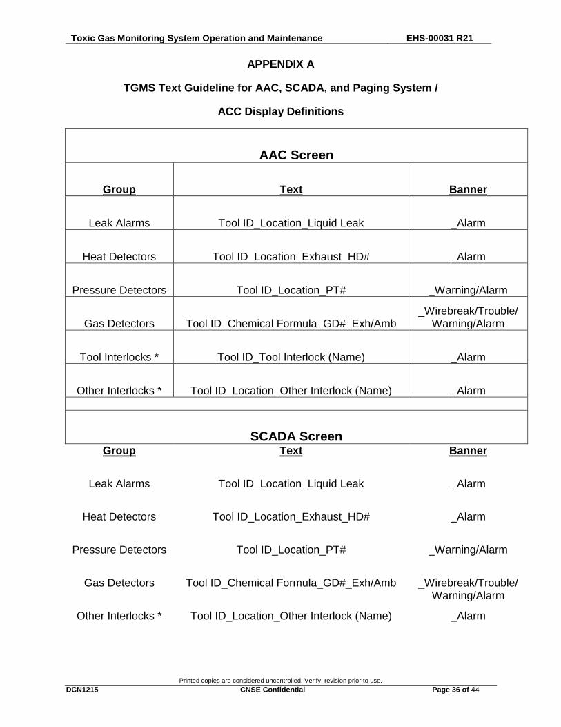
APPENDIX A
TGMS Text Guideline for AAC, SCADA, and Paging System /
ACC Display Definitions
AAC Screen
Group Text Banner
Leak Alarms Tool ID_Location_Liquid Leak _Alarm
Heat Detectors Tool ID_Location_Exhaust_HD# _Alarm
Pressure Detectors Tool ID_Location_PT# _Warning/Alarm
Gas Detectors Tool ID_Chemical Formula_GD#_Exh/Amb _Wirebreak/Trouble/
Warning/Alarm
Tool Interlocks * Tool ID_Tool Interlock (Name) _Alarm
Other Interlocks * Tool ID_Location_Other Interlock (Name) _Alarm
SCADA Screen Group Text Banner
Leak Alarms Tool ID_Location_Liquid Leak _Alarm
Heat Detectors Tool ID_Location_Exhaust_HD# _Alarm
Pressure Detectors Tool ID_Location_PT# _Warning/Alarm
Gas Detectors Tool ID_Chemical Formula_GD#_Exh/Amb _Wirebreak/Trouble/Warning/Alarm
Other Interlocks * Tool ID_Location_Other Interlock (Name) _Alarm
Toxic Gas Monitoring System Operation and Maintenance EHS-00031 R21
Printed copies are considered uncontrolled. Verify revision prior to use.
DCN1215 CNSE Confidential Page 37 of 44
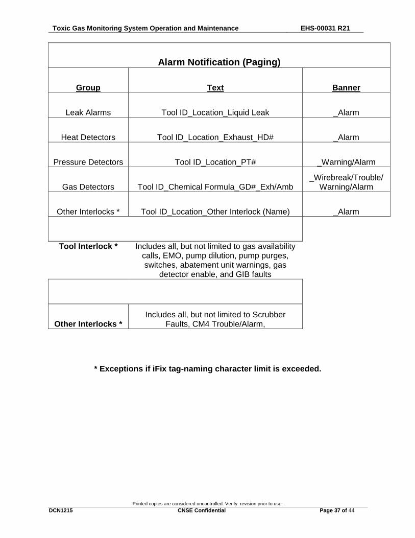
Alarm Notification (Paging)
Group Text Banner
Leak Alarms Tool ID_Location_Liquid Leak _Alarm
Heat Detectors Tool ID_Location_Exhaust_HD# _Alarm
Pressure Detectors Tool ID_Location_PT# _Warning/Alarm
Gas Detectors Tool ID_Chemical Formula_GD#_Exh/Amb _Wirebreak/Trouble/
Warning/Alarm
Other Interlocks * Tool ID_Location_Other Interlock (Name) _Alarm
Tool Interlock * Includes all, but not limited to gas availability calls, EMO, pump dilution, pump purges, switches, abatement unit warnings, gas
detector enable, and GIB faults
Other Interlocks * Includes all, but not limited to Scrubber
Faults, CM4 Trouble/Alarm,
* Exceptions if iFix tag-naming character limit is exceeded.
Toxic Gas Monitoring System Operation and Maintenance EHS-00031 R21
Printed copies are considered uncontrolled. Verify revision prior to use.
DCN1215 CNSE Confidential Page 38 of 44
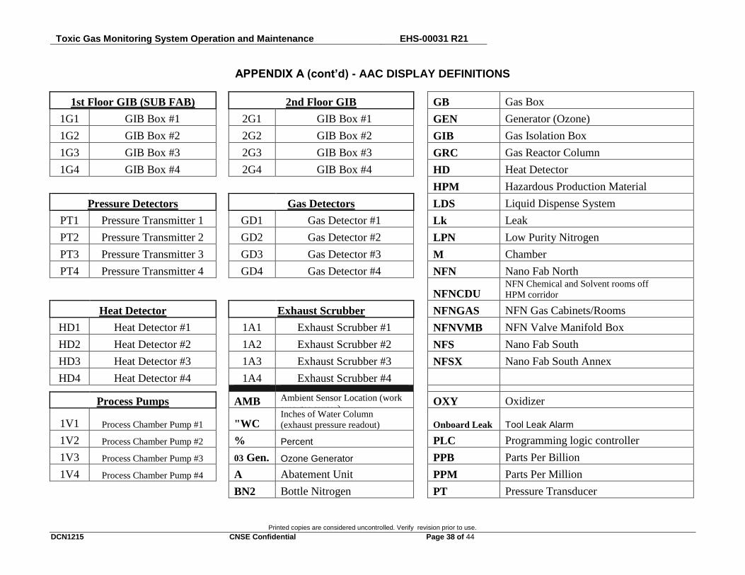
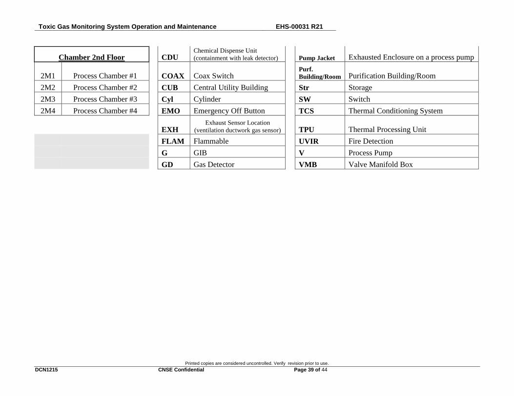
APPENDIX A (cont’d) - AAC DISPLAY DEFINITIONS
1st Floor GIB (SUB FAB) 2nd Floor GIB GB Gas Box
1G1 GIB Box #1 2G1 GIB Box #1 GEN Generator (Ozone)
1G2 GIB Box #2 2G2 GIB Box #2 GIB Gas Isolation Box
1G3 GIB Box #3 2G3 GIB Box #3 GRC Gas Reactor Column
1G4 GIB Box #4 2G4 GIB Box #4 HD Heat Detector
HPM Hazardous Production Material
Pressure Detectors Gas Detectors LDS Liquid Dispense System
PT1 Pressure Transmitter 1 GD1 Gas Detector #1 Lk Leak
PT2 Pressure Transmitter 2 GD2 Gas Detector #2 LPN Low Purity Nitrogen
PT3 Pressure Transmitter 3 GD3 Gas Detector #3 M Chamber
PT4 Pressure Transmitter 4 GD4 Gas Detector #4 NFN Nano Fab North
NFNCDU NFN Chemical and Solvent rooms off
HPM corridor
Heat Detector Exhaust Scrubber NFNGAS NFN Gas Cabinets/Rooms
HD1 Heat Detector #1 1A1 Exhaust Scrubber #1 NFNVMB NFN Valve Manifold Box
HD2 Heat Detector #2 1A2 Exhaust Scrubber #2 NFS Nano Fab South
HD3 Heat Detector #3 1A3 Exhaust Scrubber #3 NFSX Nano Fab South Annex
HD4 Heat Detector #4 1A4 Exhaust Scrubber #4
Process Pumps AMB Ambient Sensor Location (work
area gas sensor) OXY Oxidizer
1V1 Process Chamber Pump #1 "WC Inches of Water Column
(exhaust pressure readout) Onboard Leak Tool Leak Alarm
1V2 Process Chamber Pump #2 % Percent PLC Programming logic controller
1V3 Process Chamber Pump #3 03 Gen. Ozone Generator PPB Parts Per Billion
1V4 Process Chamber Pump #4 A Abatement Unit PPM Parts Per Million
BN2 Bottle Nitrogen PT Pressure Transducer
Toxic Gas Monitoring System Operation and Maintenance EHS-00031 R21
Printed copies are considered uncontrolled. Verify revision prior to use.
DCN1215 CNSE Confidential Page 39 of 44
Chamber 2nd Floor CDU Chemical Dispense Unit
(containment with leak detector) Pump Jacket Exhausted Enclosure on a process pump
2M1 Process Chamber #1 COAX Coax Switch Purf.
Building/Room Purification Building/Room
2M2 Process Chamber #2 CUB Central Utility Building Str Storage
2M3 Process Chamber #3 Cyl Cylinder SW Switch
2M4 Process Chamber #4 EMO Emergency Off Button TCS Thermal Conditioning System
EXH Exhaust Sensor Location
(ventilation ductwork gas sensor) TPU Thermal Processing Unit
FLAM Flammable UVIR Fire Detection
G GIB V Process Pump
GD Gas Detector VMB Valve Manifold Box
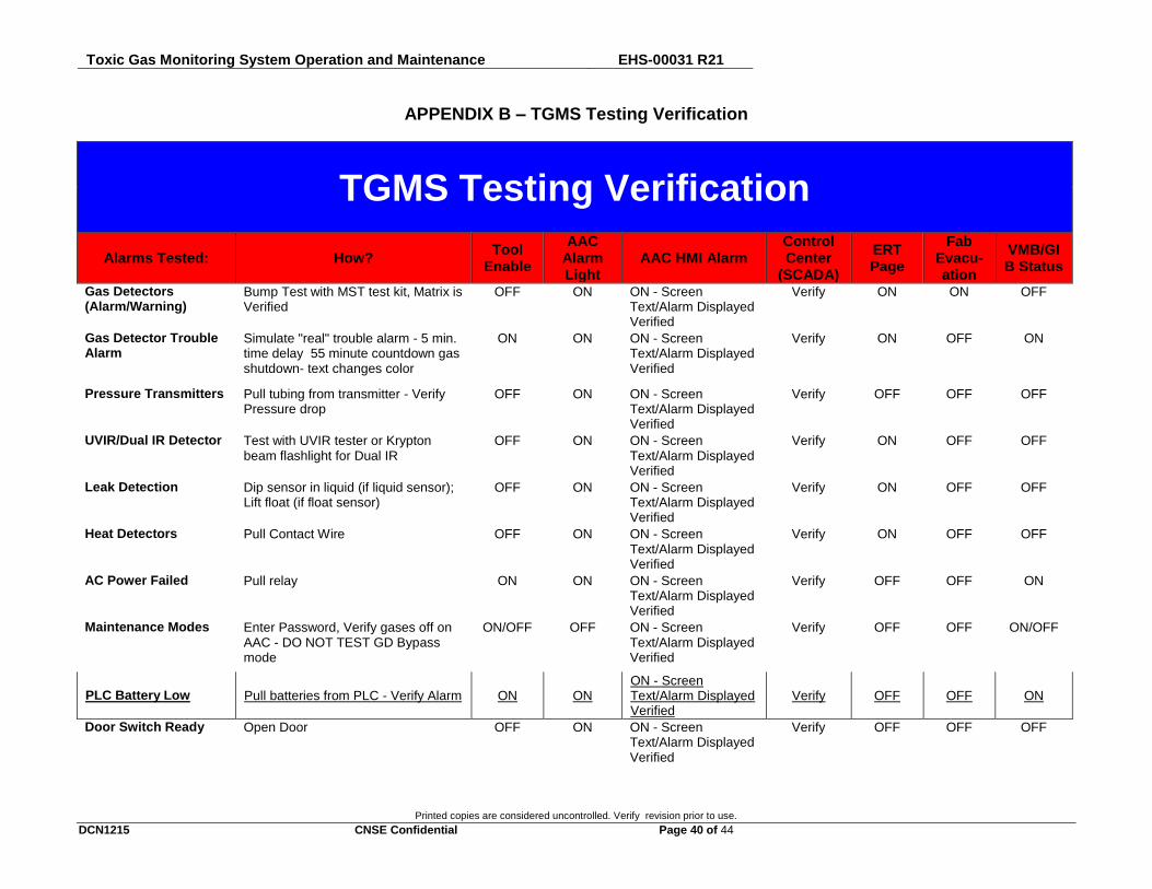
Toxic Gas Monitoring System Operation and Maintenance EHS-00031 R21
Printed copies are considered uncontrolled. Verify revision prior to use.
DCN1215 CNSE Confidential Page 40 of 44
APPENDIX B – TGMS Testing Verification
TGMS Testing Verification
Alarms Tested: How? Tool
Enable
AAC Alarm Light
AAC HMI Alarm Control Center
(SCADA)
ERT Page
Fab Evacu-ation
VMB/GIB Status
Gas Detectors (Alarm/Warning)
Bump Test with MST test kit, Matrix is Verified
OFF ON ON - Screen Text/Alarm Displayed Verified
Verify ON ON OFF
Gas Detector Trouble Alarm
Simulate "real" trouble alarm - 5 min. time delay 55 minute countdown gas shutdown- text changes color
ON ON ON - Screen Text/Alarm Displayed Verified
Verify ON OFF ON
Pressure Transmitters Pull tubing from transmitter - Verify Pressure drop
OFF ON ON - Screen Text/Alarm Displayed Verified
Verify OFF OFF OFF
UVIR/Dual IR Detector Test with UVIR tester or Krypton beam flashlight for Dual IR
OFF ON ON - Screen Text/Alarm Displayed Verified
Verify ON OFF OFF
Leak Detection Dip sensor in liquid (if liquid sensor); Lift float (if float sensor)
OFF ON ON - Screen Text/Alarm Displayed Verified
Verify ON OFF OFF
Heat Detectors Pull Contact Wire OFF ON ON - Screen Text/Alarm Displayed Verified
Verify ON OFF OFF
AC Power Failed Pull relay ON ON ON - Screen Text/Alarm Displayed Verified
Verify OFF OFF ON
Maintenance Modes Enter Password, Verify gases off on AAC - DO NOT TEST GD Bypass mode
ON/OFF OFF ON - Screen Text/Alarm Displayed Verified
Verify OFF OFF ON/OFF
PLC Battery Low Pull batteries from PLC - Verify Alarm ON ON ON - Screen Text/Alarm Displayed Verified
Verify OFF OFF ON
Door Switch Ready Open Door OFF ON ON - Screen Text/Alarm Displayed Verified
Verify OFF OFF OFF

Toxic Gas Monitoring System Operation and Maintenance EHS-00031 R21
Printed copies are considered uncontrolled. Verify revision prior to use.
DCN1215 CNSE Confidential Page 41 of 44
Alarms Tested: How? Tool
Enable
AAC Alarm Light
AAC HMI Alarm Control Center
(SCADA)
ERT Page
Fab Evacua
tion
VMB/GIB Status
Gas Calls Verify Signal on AAC (GIB/VMB/G.C.) OFF ON ON - Screen Text/Alarm Displayed Verified
Verify OFF OFF OFF
O3 Generator Ready Verify Generator shuts down OFF ON ON - Screen Text/Alarm Displayed Verified
Verify OFF OFF OFF
Purge Systems (N2) Turn off purge system and observe alarm
OFF ON ON - Screen Text/Alarm Displayed Verified
Verify OFF OFF OFF
BN2 Switch Drop indicator needle past setpoint (Verify Alarm)
OFF ON ON - Screen Text/Alarm Displayed Verified
Verify OFF OFF OFF
COAX Switch Drop indicator needle past setpoint (Verify Alarm)
OFF ON ON - Screen Text/Alarm Displayed Verified
Verify ON OFF OFF
Scrubber Fault/Warning/Alarm
Lift contact wire on Scrubber (Verify Fault/Warning/Alarm) Also verify Warning/Alarm with HD/PT/GD
OFF ON ON - Screen Text/Alarm Displayed Verified
Verify OFF OFF OFF
Tool Enable ON - Indicates Tool "Normal" Operation
OFF - Indicates Tool "SHUTDOWN" AAC Alarm Light ON - Indicates AAC Strobe Light "Flashing"
OFF - Indicates AAC Strobe Light "IDLE" AAC HMI Alarm ON - Indicates Text/Alarm displayed on AAC
OFF - Indicates AAC display is clear Control Center (SCADA) Verified - Indicates TEXT/Alarm is verified on
SCADA system/TGMS Screen @ Security
ERT Page ON - Indicates Alarm pages ERT group OFF - Indicates NO ERT group page
Fab Evacuation ON - Indicates "BLUE LIGHTS" OFF - Indicates NO "BLUE LIGHTS"
VMB/GIB Status ON - Indicates "Normal" tool operation OFF - Indicates VMB/GIB disabled
(SHUTDOWN)
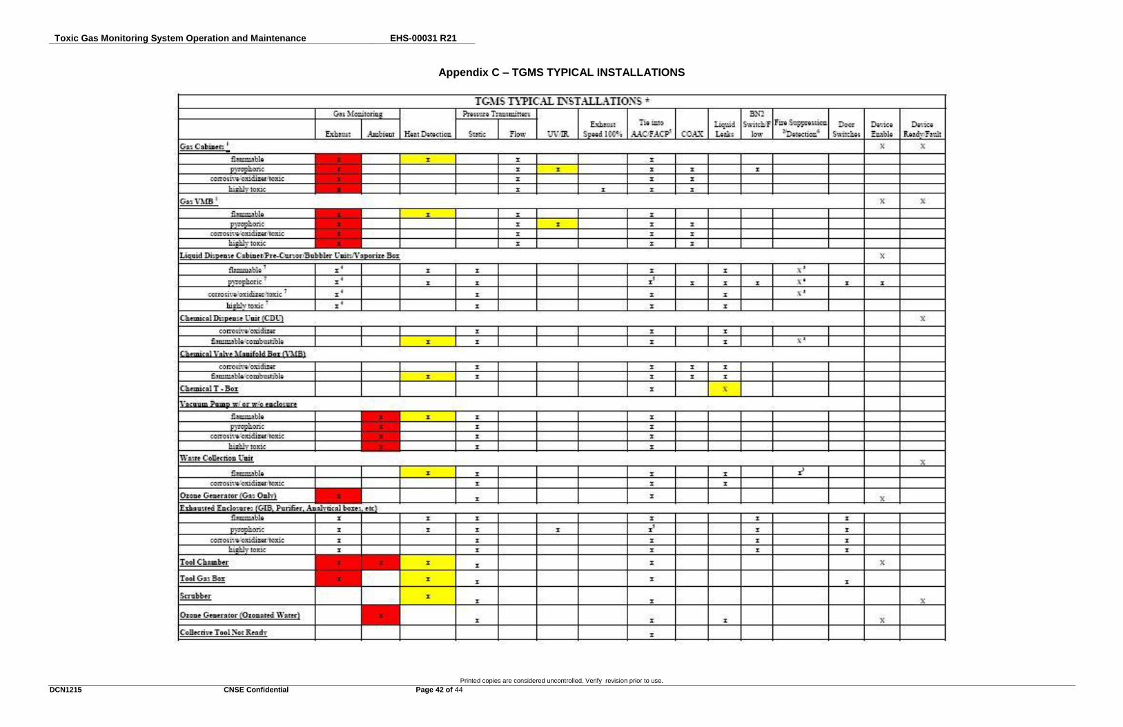
Toxic Gas Monitoring System Operation and Maintenance EHS-00031 R21
Printed copies are considered uncontrolled. Verify revision prior to use.
DCN1215 CNSE Confidential Page 42 of 44
Appendix C – TGMS TYPICAL INSTALLATIONS
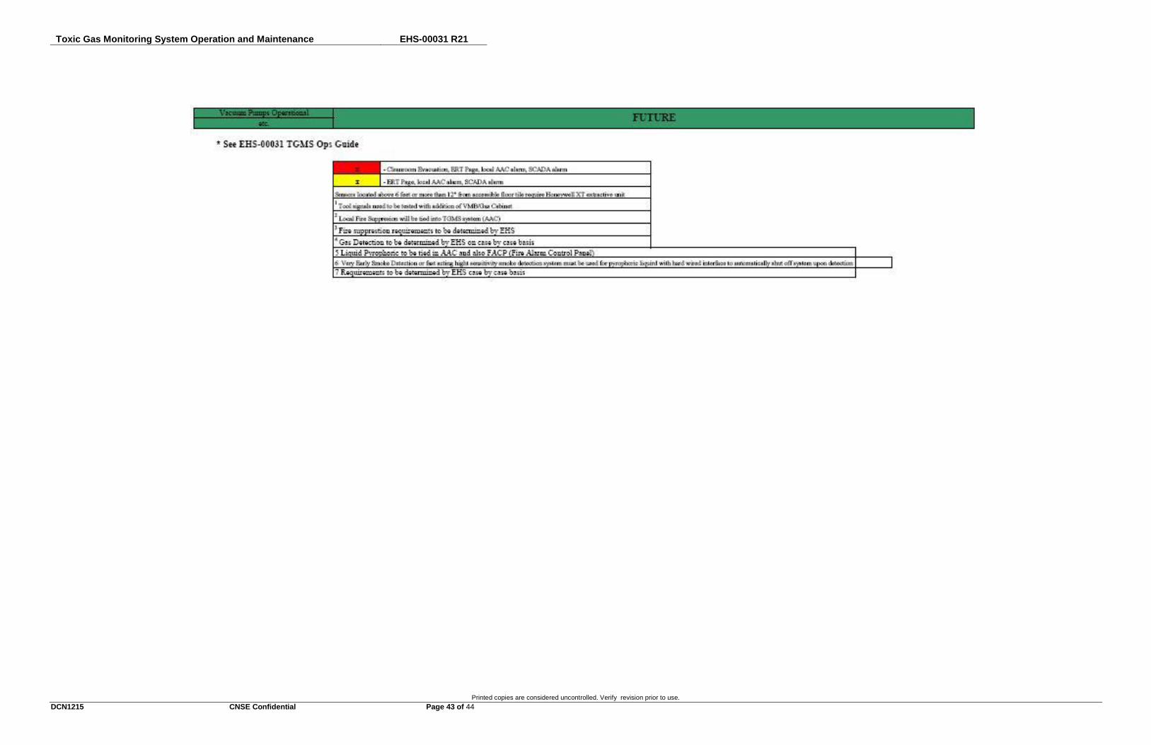
Toxic Gas Monitoring System Operation and Maintenance EHS-00031 R21
Printed copies are considered uncontrolled. Verify revision prior to use.
DCN1215 CNSE Confidential Page 43 of 44
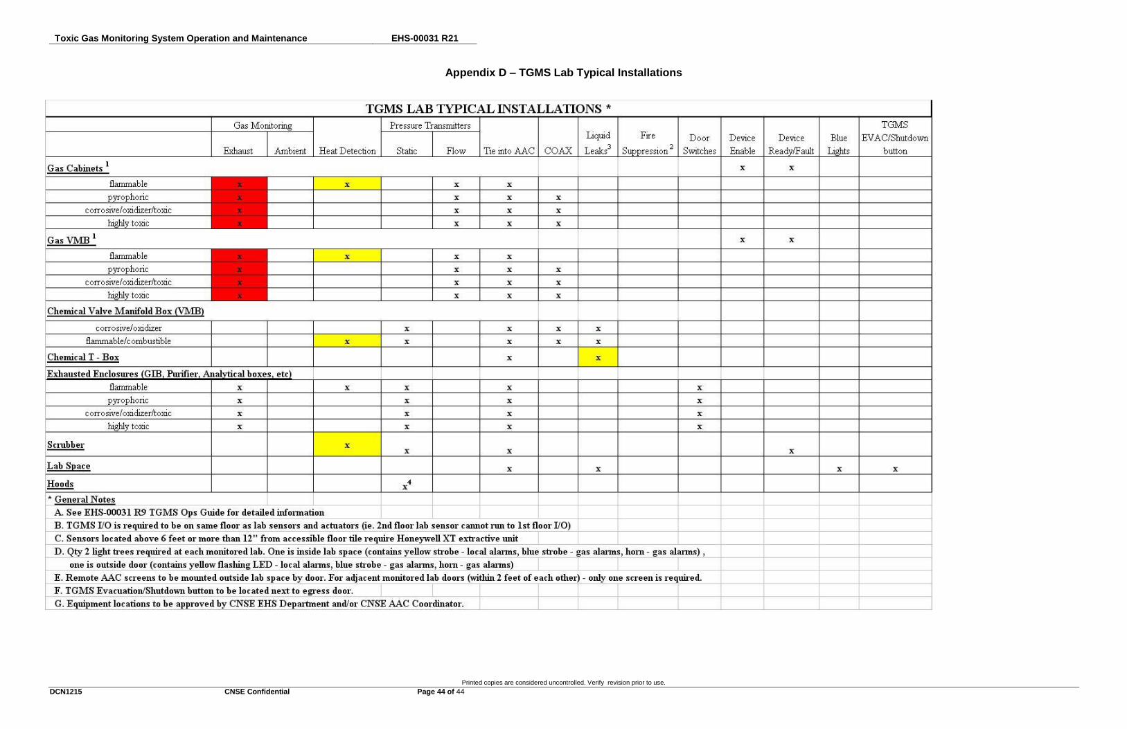
Toxic Gas Monitoring System Operation and Maintenance EHS-00031 R21
Printed copies are considered uncontrolled. Verify revision prior to use.
DCN1215 CNSE Confidential Page 44 of 44
Appendix D – TGMS Lab Typical Installations