unified approach for structural behavior of rhs t joints
TRANSCRIPT

Unified approach for structural behavior of RHS T jointsMarsel Garifullin, Kristo Mela, Markku Heinisuo
Tampere University of Technology, Tampere, Finland
METNET International Workshop
15-16 March 2017, Kemi and Rovaniemi, Finland
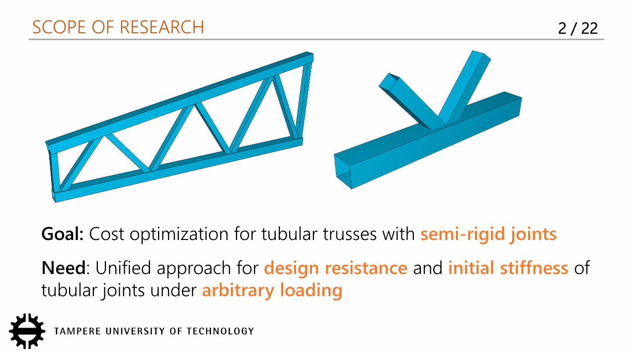
SCOPE OF RESEARCH 2 / 22
Goal: Cost optimization for tubular trusses with semi-rigid joints
Need: Unified approach for design resistance and initial stiffness of tubular joints under arbitrary loading
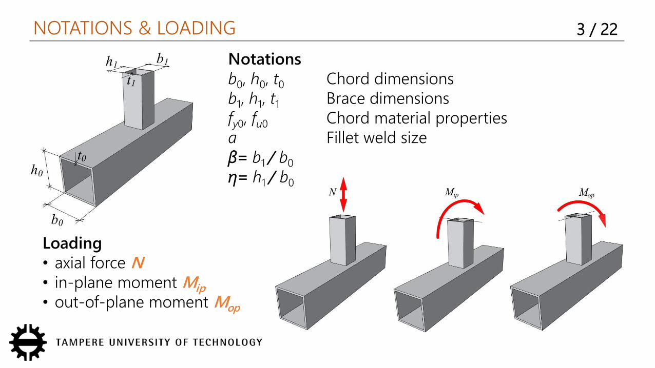
NOTATIONS & LOADING 3 / 22
Loading• axial force N• in-plane moment Mip
• out-of-plane moment Mop
Notationsb0, h0, t0 Chord dimensions b1, h1, t1 Brace dimensionsfy0, fu0 Chord material propertiesa Fillet weld size= b1 / b0
η= h1 / b0
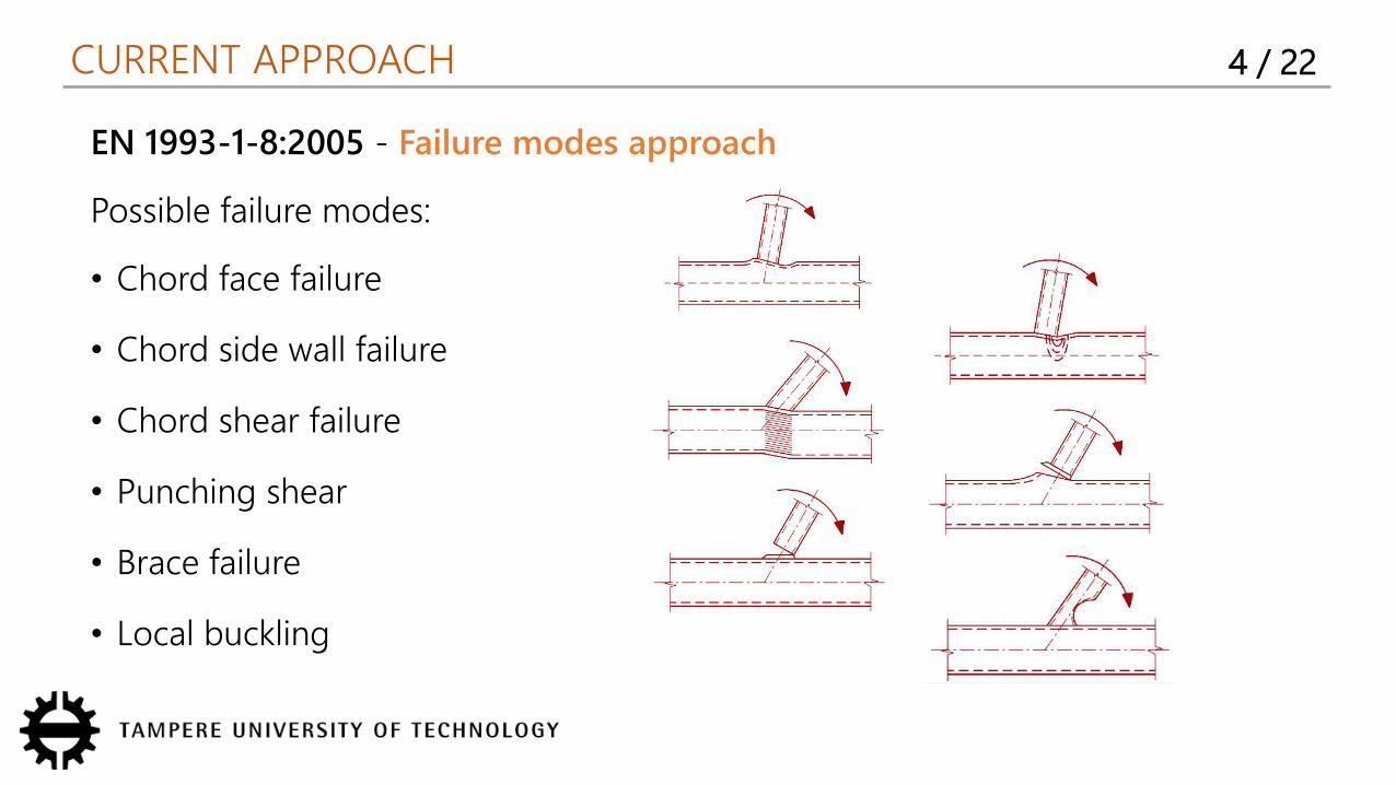
CURRENT APPROACH 4 / 22
EN 1993-1-8:2005 - Failure modes approach
Possible failure modes:
• Chord face failure
• Chord side wall failure
• Chord shear failure
• Punching shear
• Brace failure
• Local buckling
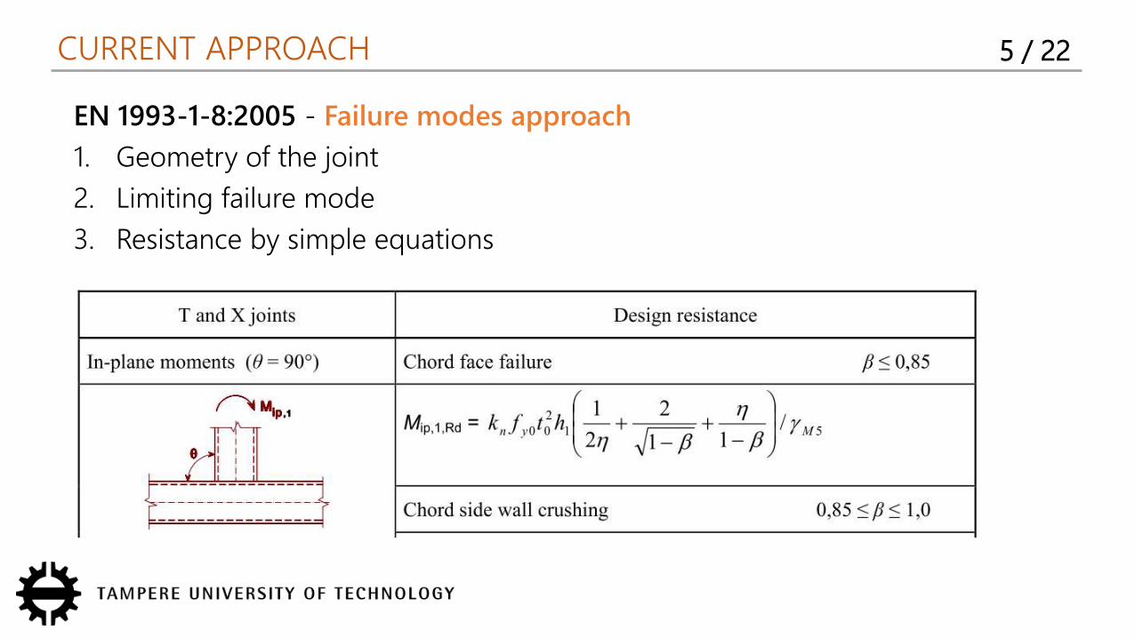
CURRENT APPROACH 5 / 22
EN 1993-1-8:2005 - Failure modes approach
1. Geometry of the joint
2. Limiting failure mode
3. Resistance by simple equations
CURRENT APPROACH 6 / 22
EN 1993-1-8:2005 - Failure modes approach
• Simple & fast
Challenges
• Restricted by cases studied
• Additional checks for welds required
• No rules for initial stiffness
Possible solution
Component method
COMPONENT METHOD 7 / 22
Brief history
1974, Zoetemeijer, bolted connections
1987, Tschemmernegg et al.
1995, Wald, column bases
1998, Grotmann & Sedlacek, rotational stiffness
2001, Weynand & Jaspart, hollow section joints
2008, da Silva, 3D joints
2009, Heinisuo et al., end plate joints
2015, Weynand et al., general approach for all types of joints
Currently: EN 1993-1-8 for joints connecting H or I sections
This research
Component method for RHS T joints under arbitrary loading
COMPONENT METHOD 8 / 22
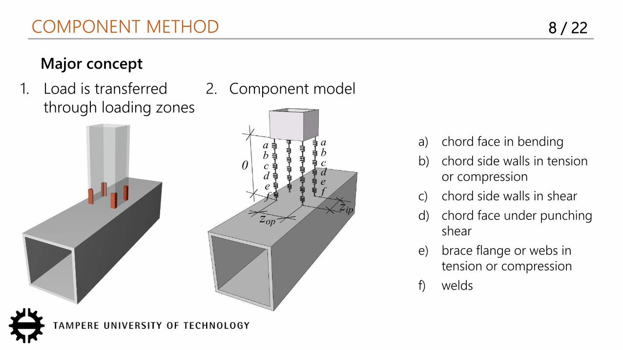
Major concept
1. Load is transferred through loading zones
2. Component model
a) chord face in bending
b) chord side walls in tension or compression
c) chord side walls in shear
d) chord face under punching shear
e) brace flange or webs in tension or compression
f) welds
COMPONENT METHOD 9 / 22
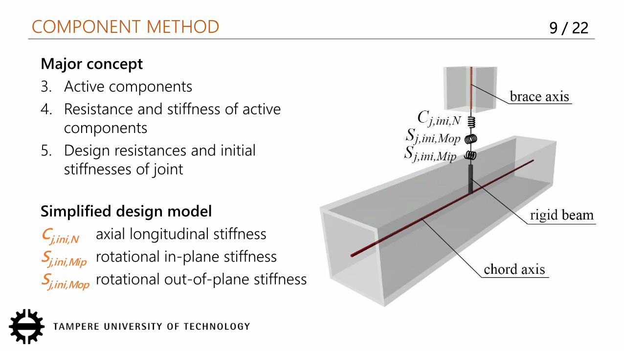
Major concept
3. Active components
4. Resistance and stiffness of active components
5. Design resistances and initial stiffnesses of joint
Simplified design model
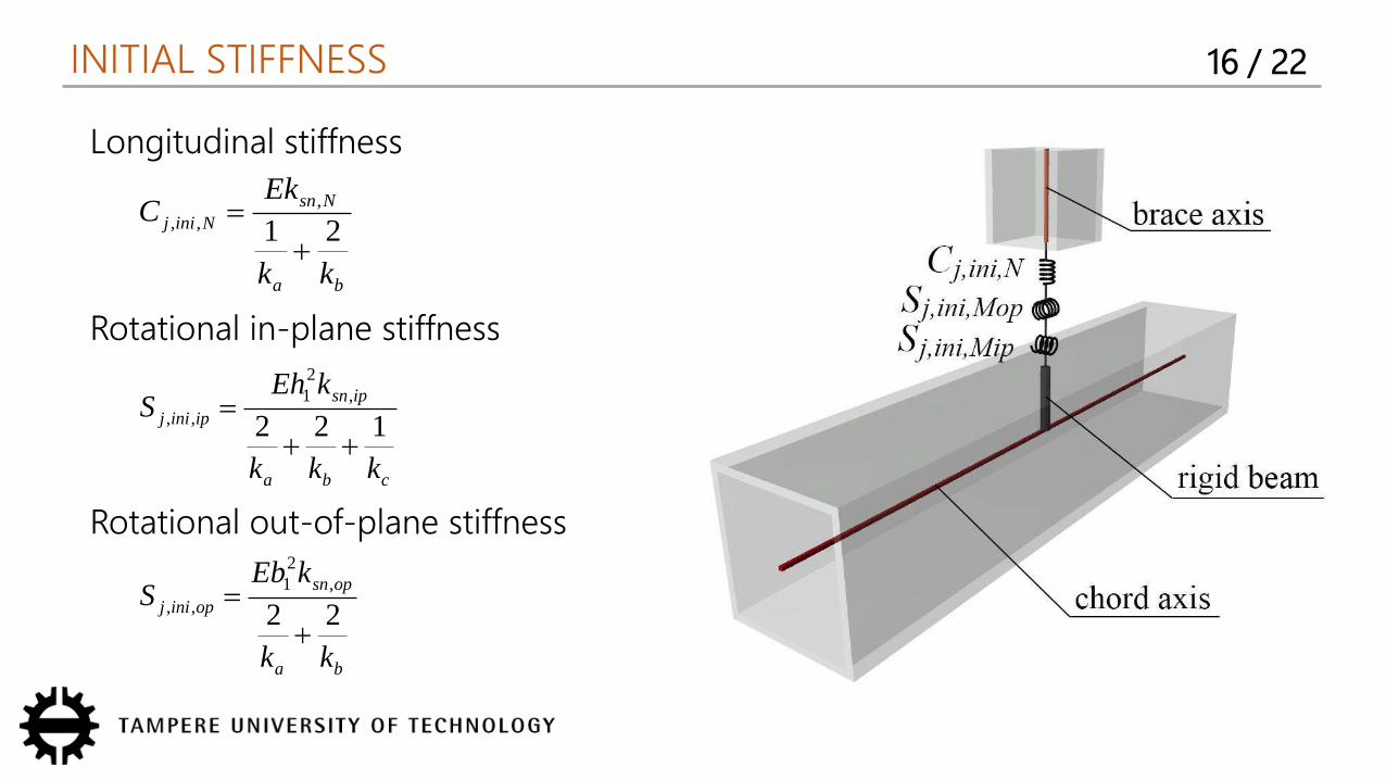
Cj,ini,N axial longitudinal stiffness
Sj,ini,Mip rotational in-plane stiffness
Sj,ini,Mop rotational out-of-plane stiffness

RESISTANCE 10 / 22
1. Active components (Weynand et al., 2015)
Component Axial force In-plane moment Out-of-plane moment
aChord face in
bending
≤ 0.85 0.85 < ≤ 1.0 ≤ 0.85 0.85 < ≤ 1.0 ≤ 0.85 0.85 < ≤ 1.0
● – ● – ● –
b
Chord side wall(s) in
tension or
compression
≤ 0.85 0.85 < ≤ 1.0 = 1.0 ≤ 0.85 0.85 < ≤ 1.0 ≤ 0.85 0.85 < ≤ 1.0
– ● ● – ● – ●
cChord side wall(s) in
shear– – – – – – –
dChord face under
punching shear
≤ 0.85 0.85 < ≤ (1–1/ ) > (1–1/ ) ≤ 0.85 0.85 < ≤ 1.0 ≤ 0.85 0.85 < ≤ 1.0
– ● – – – – –
e
Brace flange and
web(s) in tension or
compression
≤ 0.85 0.85 < ≤ 1.0 ≤ 0.85 0.85 < ≤ 1.0 ≤ 0.85 0.85 < ≤ 1.0
– ● – ● – ●
f Welds ● ● ● ● ● ●
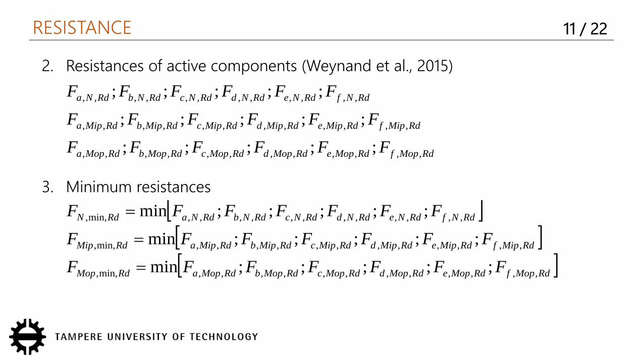
RESISTANCE 11 / 22
2. Resistances of active components (Weynand et al., 2015)
3. Minimum resistances RdMopfRdMopeRdMopdRdMopcRdMopbRdMopaRdMop
RdMipfRdMipeRdMipdRdMipcRdMipbRdMipaRdMip
RdNfRdNeRdNdRdNcRdNbRdNaRdN
FFFFFFF
FFFFFFF
FFFFFFF
,,,,,,,,,,,,min,,
,,,,,,,,,,,,min,,
,,,,,,,,,,,,min,,
;;;;;min
;;;;;min
;;;;;min
RdMopfRdMopeRdMopdRdMopcRdMopbRdMopa
RdMipfRdMipeRdMipdRdMipcRdMipbRdMipa
RdNfRdNeRdNdRdNcRdNbRdNa
FFFFFF
FFFFFF
FFFFFF
,,,,,,,,,,,,
,,,,,,,,,,,,
,,,,,,,,,,,,
;;;;;
;;;;;
;;;;;
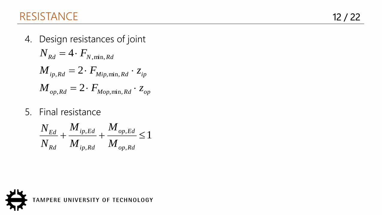
RESISTANCE 12 / 22
opRdMopRdop
ipRdMipRdip
RdNRd
zFM
zFM
FN
min,,,
min,,,
min,,
2
2
44. Design resistances of joint
5. Final resistance
1,
,
,
, Rdop
Edop
Rdip
Edip
Rd
Ed
M
M
M
M
N
N
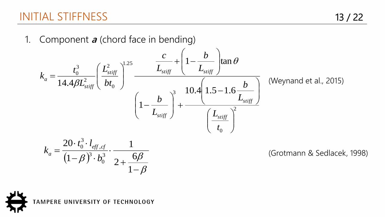
INITIAL STIFFNESS 13 / 22
1. Component a (chord face in bending)
2
0
3
25.1
0
2
2
30
6.15.14.10
1
tan1
4.14
t
L
L
b
L
b
L
b
L
c
bt
L
L
tk
stiff
stiff
stiff
stiffstiffstiff
stiffa
16
2
1
1
2030
3,
30
b
ltk cfeff
a
(Weynand et al., 2015)
(Grotmann & Sedlacek, 1998)
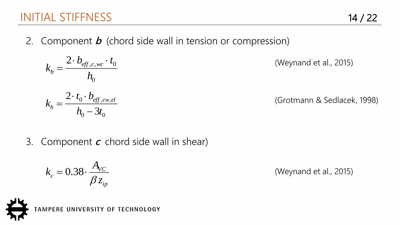
INITIAL STIFFNESS 14 / 22
2. Component b (chord side wall in tension or compression)
(Weynand et al., 2015)
(Grotmann & Sedlacek, 1998)
0
0,,2
h
tbk wcceff
b
00
,,0
3
2
th
btk elcweff
b
3. Component c chord side wall in shear)
ip
VCc z
Ak 38.0 (Weynand et al., 2015)
INITIAL STIFFNESS 15 / 22
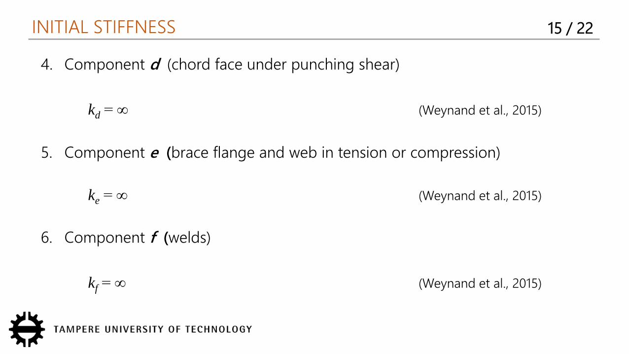
4. Component d (chord face under punching shear)
kd = ∞ (Weynand et al., 2015)
5. Component e (brace flange and web in tension or compression)
ke = ∞ (Weynand et al., 2015)
6. Component f (welds)
kf = ∞ (Weynand et al., 2015)
INITIAL STIFFNESS 16 / 22
Longitudinal stiffness
ba
NsnNinij
kk
EkC
21,
,,
Rotational out-of-plane stiffness
Rotational in-plane stiffness
cba
ipsnipinij
kkk
kEhS
122,
21
,,
ba
opsnopinij
kk
kEbS
22,
21
,,
EXAMPLES 17 / 22
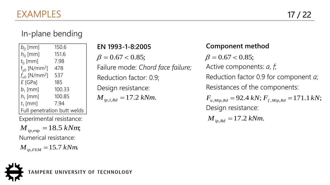
In-plane bending
b0 [mm] 150.6
h0 [mm] 151.6
t0 [mm] 7.98
fy0 [N/mm2] 478
fu0 [N/mm2] 537
E [GPa] 185
b1 [mm] 100.33
h1 [mm] 100.85
t1 [mm] 7.94
Full penetration butt welds
EN 1993-1-8:2005
Failure mode: Chord face failure;
Reduction factor: 0.9;
Design resistance:
;85.067.0
.2.17,1, kNmM Rdip
Component method
Active components: a, f;
Reduction factor 0.9 for component a;
Resistances of the components:
Design resistance:
;85.067.0
;1.171;4.92 ,,,, kNFkNF RdMipfRdMipa .2.17, kNmM Rdip Experimental resistance:
Numerical resistance:
;5.18exp, kNmM ip .7.15, kNmM FEMip
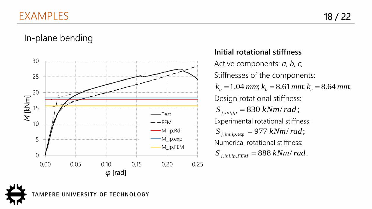
EXAMPLES 18 / 22
In-plane bending
0
5
10
15
20
25
30
0,00 0,05 0,10 0,15 0,20 0,25
M[k
Nm
]
φ [rad]
Test
FEM
M_ip,Rd
M_ip,exp
M_ip,FEM
Initial rotational stiffness
Active components: a, b, c;
Stiffnesses of the components:
Design rotational stiffness:
Experimental rotational stiffness:
Numerical rotational stiffness:
;64.8;61.8;04.1 mmkmmkmmk cba ;/830,, radkNmS ipinij
;/977exp,,, radkNmS ipinij ./888,,, radkNmS FEMipinij
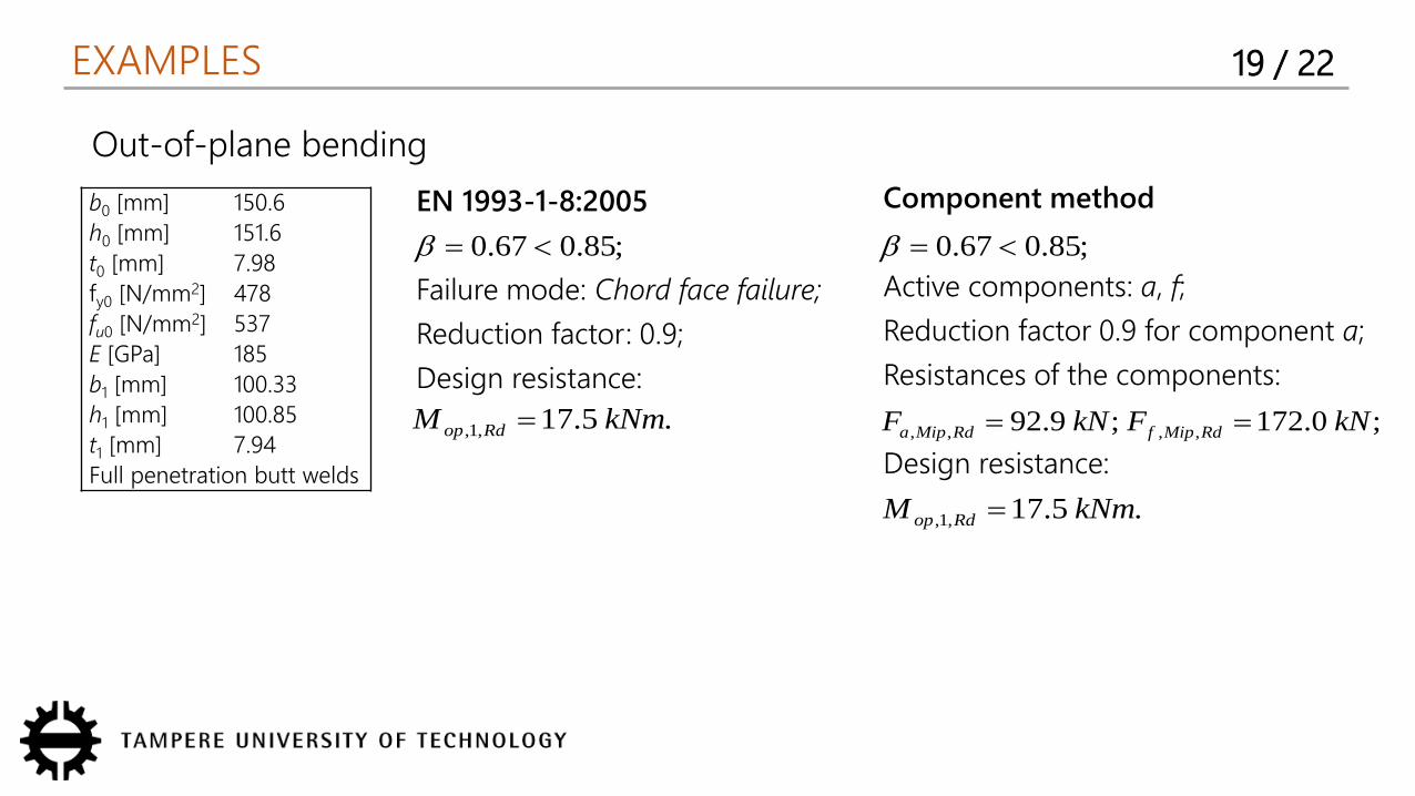
EXAMPLES 19 / 22
Out-of-plane bending
b0 [mm] 150.6
h0 [mm] 151.6
t0 [mm] 7.98
fy0 [N/mm2] 478
fu0 [N/mm2] 537
E [GPa] 185
b1 [mm] 100.33
h1 [mm] 100.85
t1 [mm] 7.94
Full penetration butt welds
EN 1993-1-8:2005
Failure mode: Chord face failure;
Reduction factor: 0.9;
Design resistance:
;85.067.0
.5.17,1, kNmM Rdop
Component method
Active components: a, f;
Reduction factor 0.9 for component a;
Resistances of the components:
Design resistance:
;85.067.0
;0.172;9.92 ,,,, kNFkNF RdMipfRdMipa .5.17,1, kNmM Rdop
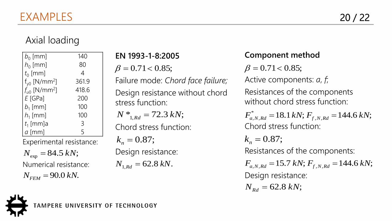
EXAMPLES 20 / 22
Axial loading
b0 [mm] 140
h0 [mm] 80
t0 [mm] 4
fy0 [N/mm2] 361.9
fu0 [N/mm2] 418.6
E [GPa] 200
b1 [mm] 100
h1 [mm] 100
t1 [mm]a 3
a [mm] 5
EN 1993-1-8:2005
Failure mode: Chord face failure;
Design resistance without chord stress function:
Chord stress function:
Design resistance:
Component method
Active components: a, f;
Resistances of the components without chord stress function:
Chord stress function:
Resistances of the components:
Design resistance:
Experimental resistance:
Numerical resistance:
;85.071.0
;87.0nk
.8.62,1 kNN Rd
;3.72* ,1 kNN Rd
;5.84exp kNN .0.90 kNNFEM
;85.071.0
;6.144;1.18 ,,*
,, kNFkNF RdNfRdNa ;87.0nk
;6.144;7.15 ,,,, kNFkNF RdNfRdNa ;8.62 kNNRd
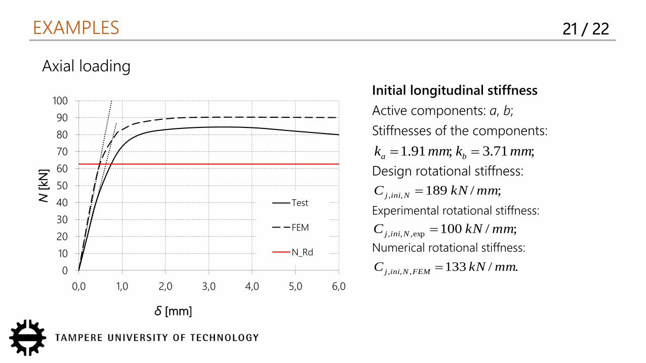
EXAMPLES 21 / 22
Axial loading
Initial longitudinal stiffness
Active components: a, b;
Stiffnesses of the components:
Design rotational stiffness:
Experimental rotational stiffness:
Numerical rotational stiffness:
;71.3;91.1 mmkmmk ba ;/189,, mmkNC Ninij
;/100exp,,, mmkNC Ninij ./133,,, mmkNC FEMNinij 0
10
20
30
40
50
60
70
80
90
100
0,0 1,0 2,0 3,0 4,0 5,0 6,0
N[k
N]
δ [mm]
Test
FEM
N_Rd
CONCLUSIONS 22 / 22
Discussions
1. Eurocode-based approach of component method -> safe design resistances
2. Larger amount of calculations
3. Unclear axial and in-plane stiffnesses, uncovered out-of-plane stiffness
4. Joints assumed to behave similarly in compressions and tension
Further investigations
1. Parametric studies for verification
2. Chord stress functions for stiffness
3. Interaction of loads
4. Reduction coefficients for HSS
5. Effect of fillet welds