ut10701 autocad utility design for the little guy...
TRANSCRIPT

UT10701
AutoCAD® Utility Design for the little guy (UT10701) Dan Leighton DL Consulting
Learning Objectives The benefits of AUD for small and mid‐sized utilities.
Required and optional elements of an AUD configuration.
Essential elements to document AUD implementation requirements.
A practical phased approach for AUD implementation.
Description Adoption is growing for AutoCAD Utility Design (AUD). Yet many small and mid‐size utilities and engineering organizations view AUD deployment as a daunting challenge.
This session will break down the core AUD implementation requirements and walk through a practical process to:
Identify and document the requirements.
Plan a phased implementation.
Develop a test plan.
Document use cases and job aids so designers can make effective use of the software.
Your AU Expert Dan Leighton has spent over 30 years doing CAD, geographic information system (GIS), and engineering work, including advanced modeling, solution analysis, and software implementation. He has also done software product management and marketing, and has led a variety of product and solution teams at several enterprise software companies. For the past 9 years as the principal consultant at DL Consulting, Ltd., Dan has been providing customized consulting, training, and implementation services to organizations using a variety of Autodesk, Inc., products, including AutoCAD Utility Design, Autodesk Vault, InfraWorks, Storm and Sanitary Analysis, and more.
In the past 4 years Dan has doubled down on AutoCAD Utility Design, providing independent training and consulting services helping AUD clients worldwide.

UT10701 – AutoCAD® Utility Design for the little guy
Page 2
The benefits of AUD for small and mid‐sized utilities AutoCAD Utility Design (AUD) has existed in one form or another for over 20 years. For most of that time, AUD was primarily used by large utilities who would work with Autodesk to provide highly customized configurations.
In 2012 Autodesk released a rewritten AUD product. With a modern model‐based foundation based on Map 3D’s Topobase technology and a flexible and robust rules engine, AUD is now easier to configure and utility‐specific configurations can be easily updated to later product releases and maintained over time by in‐house administrators. Many small and mid‐sized utilities are now adopting AUD. This paper and the associated presentation is to help utilities of modest means understand the opportunity that AUD presents and assess the practical steps required to implement AUD within their unique utility environment.
Current design practice with AutoCAD
AUD should be particularly attractive to utilities that already use AutoCAD as the design tool for electric and gas distribution system. The typical design process is as follows:
Design layout: Designers typically draw the new or modified design using standard AutoCAD tools. Here’s what a typical configuration might be:
Components are drawn using attributed blocks available on palettes.
Conductors are drawn as polylines.
Styling is handled by using layers with specific names, colors, and linetypes .
Engineering: Analysis is performed using spreadsheet calculators or 3rd party products.
Material accounting: As the design proceeds, users maintain a spreadsheet to document materials in the design.
Reports: Reports are created using spreadsheets or in some cases tables on AutoCAD layouts. Data is manually transferred from spreadsheets or spec sheets into these reports.
Work management: Project and work order data is hand typed into title blocks on a layout tab.
GIS access: Landbase and existing system data are accessed from the GIS using a homegrown process. The details vary widely but a common approach is to bring in existing data to AutoCAD as a raster background.
Figure 1 ‐ Current Practice with AutoCAD – A manual process
UT10701 – AutoCAD® Utility Design for the little guy
Page 3
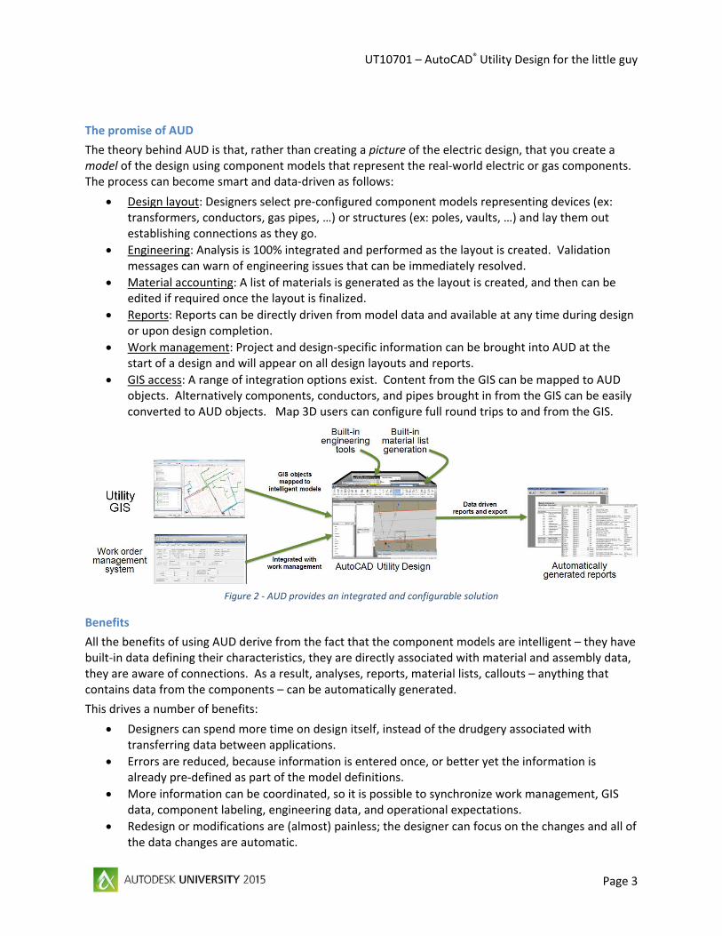
The promise of AUD
The theory behind AUD is that, rather than creating a picture of the electric design, that you create a model of the design using component models that represent the real‐world electric or gas components. The process can become smart and data‐driven as follows:
Design layout: Designers select pre‐configured component models representing devices (ex: transformers, conductors, gas pipes, …) or structures (ex: poles, vaults, …) and lay them out establishing connections as they go.
Engineering: Analysis is 100% integrated and performed as the layout is created. Validation messages can warn of engineering issues that can be immediately resolved.
Material accounting: A list of materials is generated as the layout is created, and then can be edited if required once the layout is finalized.
Reports: Reports can be directly driven from model data and available at any time during design or upon design completion.
Work management: Project and design‐specific information can be brought into AUD at the start of a design and will appear on all design layouts and reports.
GIS access: A range of integration options exist. Content from the GIS can be mapped to AUD objects. Alternatively components, conductors, and pipes brought in from the GIS can be easily converted to AUD objects. Map 3D users can configure full round trips to and from the GIS.
Figure 2 ‐ AUD provides an integrated and configurable solution
Benefits
All the benefits of using AUD derive from the fact that the component models are intelligent – they have built‐in data defining their characteristics, they are directly associated with material and assembly data, they are aware of connections. As a result, analyses, reports, material lists, callouts – anything that contains data from the components – can be automatically generated.
This drives a number of benefits:
Designers can spend more time on design itself, instead of the drudgery associated with transferring data between applications.
Errors are reduced, because information is entered once, or better yet the information is already pre‐defined as part of the model definitions.
More information can be coordinated, so it is possible to synchronize work management, GIS data, component labeling, engineering data, and operational expectations.
Redesign or modifications are (almost) painless; the designer can focus on the changes and all of the data changes are automatic.

UT10701 – AutoCAD® Utility Design for the little guy
Page 4
Required and optional elements of an AUD configuration With all this potential, why aren’t more utilities using AUD? While much of this potential is relatively easy to implement in AUD, some is not so easy! AUD must be configured. The challenge for a small to mid‐size utility is to figure out how to maximize the benefits without getting seduced by potential functionality that is difficult to implement or expensive to maintain.
With this in mind we will now consider what is required for an AUD configuration to work and what is optional and can be deferred if not a priority for the utility.
The following chart has a list along the bottom of 15 major tasks that are commonly involved in an AUD configuration. Note these are all discussed further later in the paper. Two curves are superimposed above the tasks: one that indicates how essential the task is to a useful configuration, and the second that indicates the difficulty to implement that particular functionality.
Figure 3 ‐ Implementation tasks: Difficulty vs. necessity
Of course “essential for an implementation” will differ from utility to utility. But any small and medium sized utility considering AUD should ask the following questions:
What is the minimum needed to get an implementation to work?
What constitutes “good enough” for an initial deployment?
How much do you and your team need to know to pull it off?
The real question to ask your self is “How far to the right (on the chart) do you need go to?” To answer this consider three investments of your time:
1. Get educated to the point where you know enough to make smart decisions.
2. Create a sufficiently detailed plan so you can estimate the implementation effort.
3. Set realistic expectations for management, for your team, and for yourself!
Let’s look at each of these in more detail.
UT10701 – AutoCAD® Utility Design for the little guy
Page 5
Knowing enough to make smart decisions
Whether you intend to implement AUD yourself or plan to bring on consultants to help, it’s important to understand enough about AUD to make smart decisions. The best approach is to create a prototype or a proof‐of‐concept implementation. Ideally such a proof of concept will include:
Elements from every one of the 15 implementation tasks shown on the chart, as well as any other implementation tasks you believe are required for your AUD solution.
Essential bits of every type of design you plan, including underground electrical, overhead electrical, gas, water, or any other domain.
Data setup associated with any planned interfaces. You don’t have to build the interfaces in a proof‐of‐concept, but at a minimum you need to understand that you can receive or deliver the interfaced data.
Creating a proof‐of‐concept is useful for reasons beyond self‐education. A prototype will help refine your thinking about what is essential in a configuration, and how to stage the implementation over time. A proof‐of‐concept also provides a means to show others in the organization how AUD will work, and help other teams begin planning for integration on their side.
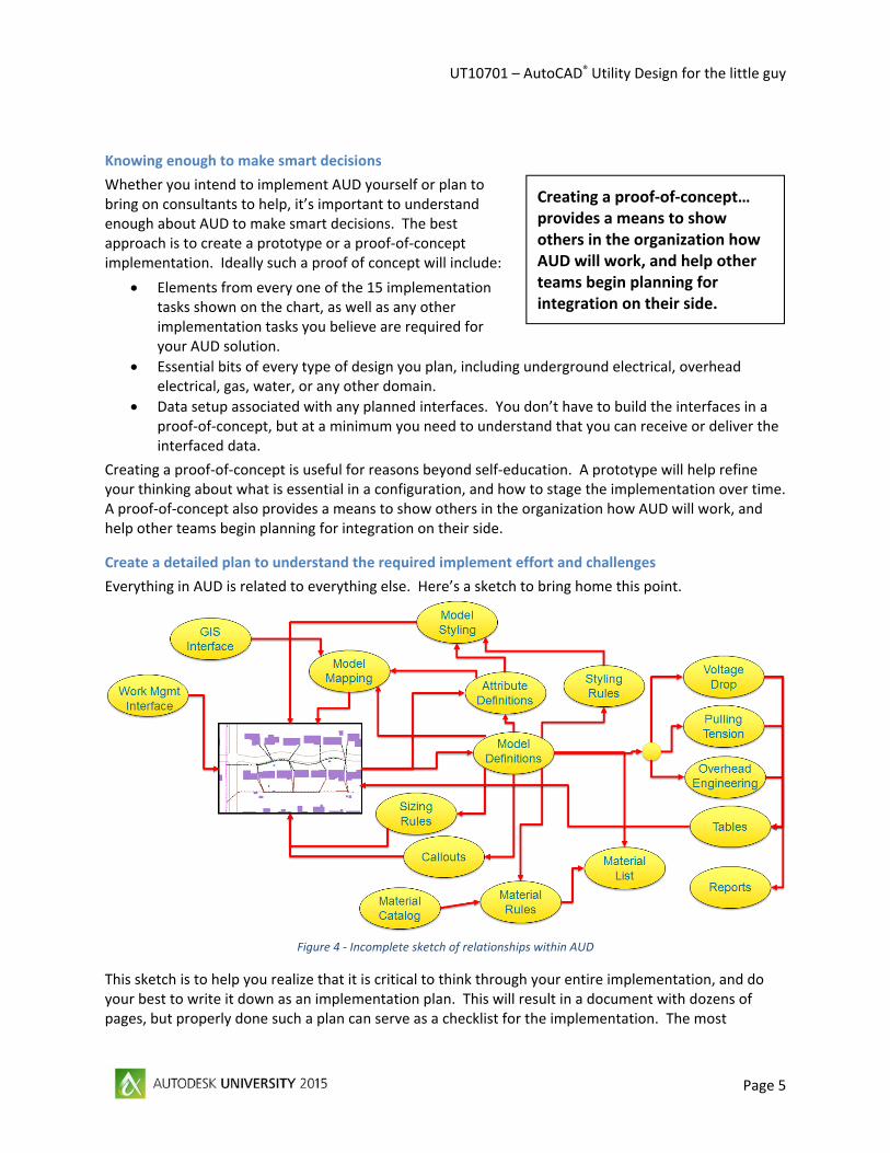
Create a detailed plan to understand the required implement effort and challenges
Everything in AUD is related to everything else. Here’s a sketch to bring home this point.
Figure 4 ‐ Incomplete sketch of relationships within AUD
This sketch is to help you realize that it is critical to think through your entire implementation, and do your best to write it down as an implementation plan. This will result in a document with dozens of pages, but properly done such a plan can serve as a checklist for the implementation. The most
Creating a proof‐of‐concept…
provides a means to show others in the organization how AUD will work, and help other teams begin planning for integration on their side.

UT10701 – AutoCAD® Utility Design for the little guy
Page 6
important aspect of creating the plan is that as you working on each topic you’ll recognize how that section relates to other topics. This will help ensure you don’t miss important items.
For example, you may think you’ve defined all of the required attributes associated with junctions. But later when you are documenting the implementation plan for a conductor summary table, you may realize
you need to identify conductors based on the junctions at each end. As a result you need to provide a means for users to enter identifiers for each junction. Indeed it is impossible to write a full AUD implementation plan from start to finish, because it is so common to realize forgotten linkages that need to later be completed.
Setting realistic expectations
AUD’s greatest strength is its configurability. But beware: if you ask “Can AUD do ‘X’?”, the answer is almost guaranteed to be yes, because you can configure it or extend it so that ‘X’ is indeed possible. And if you ask your management if ‘X’ might be useful, their answer is again likely to be yes.
A useful phrase with respect to successful AUD installations is “remember the 80‐20 rule”1. For every awesome thing that might be possible with AUD, ask if the effort to implement that functionality is worth the cost. And based on this thinking, manage expectation of both management and users. Some basic guidelines…
Set these expectations…
Efficient OH and UG design layout.
Automatic layout stylization.
Automatically select sweeps and pole heads.
Create near‐complete material list as you design.
Voltage drop analysis as you design.
Pulling tension analysis as you design.
Watch out for these expectations…
“Round trip” GIS updates.
“Seamless” GIS integration.
“Automatic” overhead engineering.
Rules will prevent engineering errors.
Anyone who knows AutoCAD can do electric and gas distribution design!
A practical phased approach for AUD implementation Every AUD implementation will be different. But it is essential to think of implementations with at least three phases:
Phase 1: Proof‐of‐concept
As mentioned earlier, a proof‐of‐concept phase is important for a variety of reasons. While it may not be practical to have elements that touch on every aspect of the final envisioned solution, a substantive pilot implementation will give the utility and the implementation team a foundation for making decisions based on practical experience.
1 The 80‐20 rule, also known as the Pareto principle, states that for many events, roughly 80% of the effects come from 20% of the causes. With respect to AUD this generally means that 80% of the implementation cost is spent on implementation functionality that is only used 20% of the time.
The most important aspect of creating an implementation plan is that, as you work on each topic, you’ll recognize how that section relates to other topics. This will help ensure you don’t miss important items.

UT10701 – AutoCAD® Utility Design for the little guy
Page 7
Phase 2: Initial deployment
A good starting point for the initial deployment is to ask “How little can we get away with?” Most initial deployments have several goals:
Show that AUD can be used by real designers creating real designs.
Demonstrate improved productivity.
Illustrate advanced functionality in action.
While AUD has the potential to perform intricate engineering analysis of complex overhead design scenarios, you should really focus on more prosaic functionality that new users can adopt quickly with proven productivity benefits. For example:
A near‐perfect material list is ready the instant the design is complete.
Drawing annotation is automatically updated when changes are made.
Voltage drop analysis takes only minutes with no manual data transfer.
Think carefully about the rollout for the initial deployment. Remember that you’ll need to train users in the right way to use AUD. Consider limiting design to only underground layouts, and indeed limiting design to only one or two types of design projects for the initial users. The key is to plan an initial deployment that will generate a positive impact on the organization.
Phase 3: Subsequent deployments
Once the initial deployment is successful it’s time to plan subsequent deployments. Ideally these will focus on a new areas of functionality:
New domains, for example adding overhead design.
New features, for example better GIS integration.
The advantage of structuring an implementation with phased follow‐on deployments is that users only have to learn so much at any given time, and will have a chance to become comfortable with using AUD with a limited set of features before trying to absorb new functionality. What’s more, the users, now understanding the way AUD works, will have an easier time absorbing the underlying concepts of new features and thus will have a faster learning curve.
Essential elements to document AUD implementation requirements At this point let’s take a deeper look at AUD implementation planning. Here’s a list of the elements that should be planned for in any AUD requirements or design document:
1: Feature classes: A list of all types of components used within designs and what AUD feature class will be used to represent each component type.
2: Required attributes: A list of all the model attributes to be populated within each feature class, as well as custom attributes to be created and high‐priority attributes for user review and update during design.
3: Models for each feature class: Although a requirements document may not list all the specific models to be created, it should clarify what is a model for each feature class.
4: Supported status values: Unless AUD is only used for designing new facilities, it is necessary to define all of the status values a user may assign to components and how each status option will be treated.
5: Component styling: Styling needs to be defined for each status and each component variation.

UT10701 – AutoCAD® Utility Design for the little guy
Page 8
6: Automatic component selection: For some types of components (especially sweeps and pole heads), it is best for AUD to make the initial model choice. The logic for this needs to be defined in the design document.
7: Basic material ordering: The document should define the basic material ordering approach, documenting how models in the layout relate to assembly or part numbers in the material catalog.
8: Material ordering exceptions: There are always exceptions within material ordering, and this should all be identified and the logic associated with each exception should be defined.
9: Callouts and annotation: For each feature class where a callout is required, the content of that callout and the source of that content should be documented.
10: Data driven tables and reports: If data‐driven tables are to be included in drawing layouts or if they are required in output reports, then the content of each table should be defined along with the source of the data or calculations required to populate the cells.
11: Engineering plans: The plan should determine how each of the analyses within AUD will be implemented. This includes settings for the model attributes of each involved component, settings for the control properties, and modifications to rules if required.
12: GIS interface: While it’s easy to say “we want everything in the GIS to be brought into AUD”, in reality very little information is required for design purposes. The plan should be specific about what information is important both coming from the GIS and what might be returned.
13: Work management interface: Most utilities have some kind of work management system. The project information is not only used for reports and title blocks, but can be integrated into rules themselves and therefore affect analysis and model selection. All of this should be noted in detail in the requirements document.
All of this sounds great but the devil is in the detail. Therefore each of the above topics is expanded on the following pages.
1: Identify the feature classes you will use
Each OOTB AUD template comes with a set of pre‐defined feature classes. One important thing to note about AUD is that you must use these feature classes. While it’s theoretically possible to add more or modify the ones provided, Autodesk recommends that you do not do this!
It would seem simple to determine which feature class to use for each type of component in the design. Poles would go in the Pole (structure) feature class, transformers would go in the Transformer (device) feature class, and so forth. But there are some tricky considerations:
No “right” feature class: You may have components that don’t obviously fit into any predefined feature class. This is especially the case for gas implementations where the list of 2016 AUD feature classes is limited. In these cases it is acceptable to repurpose unused feature classes to store the information. For example you rename the “House Connection” feature class and use it to store all cathodic protection related point components.
Too much stuff in a feature class: There are some cases where a feature class seems overly broad. In the OOTB configuration the Gas Fittings feature class contains every conceivable type of fitting (Tees, Elbows, Caps, Stoppers, …) as well as non‐fitting items like anodes. This is where a proof‐of‐concept project is invaluable to figure out what will make the most sense for your implementation.

UT10701 – AutoCAD® Utility Design for the little guy
Page 9
Device vs. structure: Sometimes with electric implementations you will have component that sounds like a structure (example: a service pit) but behaves like a device (example: a junction). In this case you could either define two objects – a structure within the handhole feature class called a “service pit” and a junction device that is always included within the service pit. Alternatively you could simply create a junction model called “service pit”. This again is where a proof‐of‐concept can help to identify the best practical approach.
The bottom line is to appreciate the purpose of a given component type into a given feature class. And in many cases there is no practical (in AUD terms) difference between various feature classes. For many types of components, the important consideration is to know what role a given feature class should play. From that standpoint, feature classes break down into the following categories:
Classes that play a role in electric analysis: This includes transformer, conductor, service point, and junction.
Classes that play a role in structural analysis: This includes ducts, sweeps, poles, and pole heads.2
Classes that participate in gas network connectivity: This includes gas pipes and gas fittings.
Everything else: If a component doesn’t fit into the first three categories, then how it is categorized in terms of feature class is less critical.
Bottom line: Just because OOTB AUD has a fixed list of feature classes, that doesn’t mean that you a) have to use all of the provided class and b) that you can’t repurpose feature classes for “other” components.
2: Determine required attributes for each feature class
The OOTB AUD configurations include a comprehensive set of predefined attributes for each feature class. You need to determine which attributes you will use, and what additional attributes are required.
Several things will drive the decisions around what attributes are necessary:
Is an attribute one of the core attributes that is always used regardless of feature class? This includes “Model Name”, “Model Group”, “Status”, and several other obvious candidates.
Is an attribute required for analysis? If yes, it needs to be populated when the models are initially loaded.
Is an attribute required because of the desired interface with the GIS? For example you may want to have the “Date Installed” available for existing components queried from the GIS.
Is an attribute required because of special functionality you plan to implement using AUD? For example you may want to automatically generate cable labels and therefore need to add 3 additional fields for the labels associated with each phase. Or you may use attributes to help determine styling.
A recommended practice for defining your planned implementation is to create three lists in your requirements documentation:
Attributes required when loading models
New implementation‐specific attributes
2 One can argue that feature classes that store pole‐mounted components like switches or reclosers also take part in structural analysis, but their role is limited to pole leveling and pole clearance and is not considered in many implementations.

UT10701 – AutoCAD® Utility Design for the little guy
Page 10
High priority attributes to be easily accessible to users3
Bottom line: Make a list and check it twice. Think through all the attributes you’re planning to have for each feature class and know why you’re including them and how they will be used.
3: Define the list of models for each feature class
An essential part of any AUD implementation is to define models to represent all components used in a design. A good first cut is to ask: “Am I likely to draw this component in my design drawings?” If the answer is yes, you should have a model to represent that component.
Beyond the obvious components there are the unseen components that warrant having models, specifically pole heads and sweeps.
Beyond these obvious cases it gets a bit trickier. Here are some cases to consider:
Items that are ordered with model components likely don’t need to have their own models. For example if you always order 3 elbow terminators whenever you connect a 3 phase cable to a pad mounted transformer, or you always order a meter of tracer conductor every time you order a meter of MDPE gas pipe, you don’t need models to represent the terminators or the tracer wire.
If you draw a cable junction box for HV cable connections but the junction boxes are a non‐standard item and the dimensions are customized for each box, you may only need to define one model and make the dimensions attributes that you can enter whenever a junction is drawn.
Most utilities have numerous components in the field that have no equivalent in the inventory of new components. Generally you don’t need to create models for all of these as most of the time they aren’t being ordered and they aren’t participating in analysis within new designs.
In many cases a good alternative to having dozens of models is to have a single model with attributes that provide further details. For example you may have HV pole mounted switches that are similar but have different fusing arrangements and different size fuses. Rather than defining a dozen different switch models you may be better off defining a single switch model with two feature attributes defining fuse type and fuse size.
Ultimately there are four questions to consider:
Will it be easier to select if you have a distinct model?
Will it be easier to style (display) if you have a distinct model?
Will it be easier to order if it is a distinct model?
Is a distinct model required for analysis to work properly?
Bottom line: Unless the answer to one of these questions is yes – you may not need to create as many models as you think!
4: Figure out what status values you need
Status is one of the most understated and misunderstood features in AUD. First, there are two status values for every component: “Status” and “Status Internal”. Status (let’s call it “Visible Status”) is what
3 AUD has a feature that allows you to categorize feature and model attributes. In many implementations this is used to group attributes to simplify access and management by designers. For example you might assign a category of “1: Key Attributes” to Model Name, Description, and Status, and a second category of “2: Assess/Update” to attributes specific to a feature class that the user should always review and update.
UT10701 – AutoCAD® Utility Design for the little guy
Page 11
the user generally sees and you can define as many status choices as you want. Under the hood there are five possible “status internal” values, and each Visible Status value gets mapped to one of these internal status values.
You need status values to satisfy all of the different status variations that components might experience within your design. You might just want to rename the OOTB values, for example change “New” to “Proposed”. But here are some other status values you might need to consider:
Status for items being replaced in the design.
Status for items being removed in the design.
Status for items being modified in some way in the design.
Status that reflects the status of the object as imported from the GIS.
Ultimately status in AUD affects three things:
Engineering: AUD’s built‐in engineering functions use a component within any given analysis depending on the value of Status Internal. So if you’ve mapped the visible Status value of “Abandoned” to the Status Internal value of “Removal”, then a conductor marked “Abandoned” won’t be used in voltage drop analysis.
Styling: Status is often used to determine component appearance. This is driven by styling rules that you write, so you can use either Status Internal or the visible Status value.
Material ordering: Status is also important for determining if a component is included in the material order. Like styling, this is entirely under your control.
Bottom line: Define status values that your users will expect (and understand) for your deployment and understand how to map them to Status Internal for the sake of inclusion in engineering.
5: Identify the styling for components
For most utilities, especially those currently using AutoCAD, styling for point objects is fairly simple. Styling for these objects is usually determined by three things:
The feature class (transformers look different than poles).
The status (new poles go on the “NewStuff” layer, removed poles go on the “RemoveStuff” layer).
The subclass for an object (draw concrete poles using the CP block, wood poles with the WP block).
To create a plan for the point object styling, start by documenting all of the blocks currently in use. These all need to be made consistent in terms of scaling, layers used, proper use of “ByLayer” and “ByBlock” and so forth.
Conductor styles can get a bit more complex, but if you’re a small or mid‐sized utility consider updating your styling approach for conductors and conduits in a fashion that is “AUD‐friendly”.
Once you know what you want in terms of styles, leverage the power of AUD’s model‐driven approach to simplify the required styling rules:
Create a model attribute called “StylePrefix” and put a unique code in for each subclass.
Use the Choose Style by Name rule to algorithmically select the correct style.
Done right, you can implement styling with less than 10 rules.

UT10701 – AutoCAD® Utility Design for the little guy
Page 12
Bottom line: Plan and rationalize how styling should be in AUD. Use this as an opportunity for your utility to clean up styling. And learn about the shortcuts that can reduce styling implementation to a matter of hours which are touched upon in the last section of this paper.
6: Create a plan for automatic component selection
AUD has a set of “sizing” rules that are useful, misnamed, and misunderstood. Usually these are demonstrated in the context of voltage drop. If the load is too high then AUD will “automatically resize the conductors and transformers” to address the problem.
While this makes for a great demo, it is not the primary use of these rules (in fact many utilities want designers to make sizing decisions – not AUD!) The rules are essential however to choose invisible components like sweeps and pole heads, or to save time by selecting the most appropriate component as the layout changes. In a perfect world they would be called “selection” rules!
Sizing rules define a set of filters so AUD can automatically choose the most appropriate model based on model attributes. For example when you draw a sharp bend in a duct, AUD will recognize that a sweep (conduit bend) is required. I want a bend that is (filter 1) made of the right material and (filter 2) has the right diameter and (filter 3) has a bend radius that is greater than the cable’s minimum bend radius.
When documenting the implementation requirements, make a list of all the feature classes where such automatic selection would be useful. This almost always includes sweeps and pole heads. It might also include the following:
Junctions (filter #1 = voltage match, filter #2 = has enough connectors for the # of wires)
Risers (filter #1 = voltage match)
Gas fittings (#1 = # of connecting pipes, #2 = material, #3 = pipe diameters, #4 = angles…)
Bottom line: If you can’t specify a default model in AUD or if the default models aren’t the way to go (as with pole heads), consider automatic selection to initially choose the model to be inserted.
7: Determine basic material ordering approach
The essence of AUD material ordering is simple: “I drew an ‘X’, so I need to order an ‘X’.” And for many small and mid‐size utilities this definition is adequate for a high percentage of the components used in a design. The only remaining question is how to map the AUD model selected to the correct material code. There are a couple approaches to consider:
Make the model IDs match the material catalog codes: This approach works great if either the material catalog codes are user‐friendly (WP404 in the catalog represents a 40’ class 4 wood pole) or if the designers have memorized all the codes (“I know that 50002213 is a 40’ class 4 wood pole”).
Use model IDs that make sense and put the internal code into the CU model attribute field. This way the user can select the WP404 model and the AUD material order will list 50002213 as the material code.
The advantage of using a simple material code mapping and recognizing that the basic material ordering approach works for most components within small and mid‐sized utilities means that many of the material ordering rules are very simple to implement!
There are of course myriad exceptions to this basic material ordering approach, but these are discussed in the next section.

UT10701 – AutoCAD® Utility Design for the little guy
Page 13
Bottom line: Aim to define a basic approach for material ordering that is simple, user‐friendly, and easy to implement.
8: Specify common material ordering exceptions
Life would be really simple if the only materials to be ordered were the things you drew, but there are always exceptions. It is practical with AUD to define rules for virtually any exception, but when planning an implementation you’ll want to document all the exceptions in your plan.
Material exceptions generally include two parts:
The logic to determine when an exception applies.
The specifics of what additional materials are required.
Consider these examples:
Logic What to order
Order 3 terminations for each primary cable connected to a pad‐mounted transformer
If transformer attribute TermType = “Fused” then order Part # 2665 (Fused Elbow) otherwise order part # 2666 (Dead Break Termination)
If plastic pipe (HDPE or MDPE) then order tracer wire.
Order 8500940 tracer wire equivalent to the pipe length.
There may be a large number of exceptions. If you are doing a phased implementation then focus on the exceptions associated with each phase.
Bottom line: Consider material ordering exceptions separate from the basic material ordering approach. See the notes on smart implementation strategies at the end of this paper for ideas on how to do this.
9: Identify required data‐driven callouts and annotation
It is impossible in electric and gas drawings to convey all of the component information in a graphical fashion, and so for many designs callouts or annotation are used to document design details. In AUD these callouts can all be data‐driven as all the data is available with the underlying models.
The design document should identify all feature classes where such callouts are required. And for each callout it should include a sketch to illustrate what each callout will look like, and details associated with each sketch regarding exactly what data appears and where it comes from or how it is calculated.
Here are two examples:
Here there are three lines describing the parallel pillar:
Line 1: Model description + State + “(“ + SpecID + “)”
Line 2: Only included if attribute for bollard protection is true Line 3: Custom feature attribute with designer note
Here there are two lines defining the gas main:
Line 1: Status + Diameter + Material + Pressure + Model Group
Line 2: Custom feature attribute with designer note to describe the pipe’s offset from the street centerline
Figure 5 ‐ Examples of requirements definition for callouts

UT10701 – AutoCAD® Utility Design for the little guy
Page 14
Bottom line: The more detail on how a data‐driven callout will work, the better. By working out the details in design you’ll recognize additional design requirements (for example in these samples both had the need for a custom feature attribute to hold a design note).
10: Identify data‐driven tables
Tables commonly appear on design documents to convey additional information to field crews and engineers. Electric design drawings often include a cable or conductor schedule. Gas design drawings often include tags to indicate where fittings in the material list appear on the design layout. Like callouts, these tables can be driven by model data, streamlining the layout and ensuring data consistency in the final document set.
The design document should identify all such tables, and like callouts should specify where data in each table column is sourced. In addition the design document should define how tables are generated and placed into the drawing, especially since many tables require formatting and placement into a paper space layout. Figure 6 shows an example of an annotated data‐driven table.
Figure 6 ‐ Documentation for requirements for a cable/conduit table
Bottom line: As with callouts, the more detail provided, the better. By working out these details you’ll be able to identify gaps in information or any additional rules required. For example the sample table shown displays voltage drop and flicker. Consequently a means must be provided to get voltage drop information from the analysis results onto each cable to facilitate providing the information in the table.
11: Plan the approach for engineering analyses
There are two aspects to using AUD’s engineering analysis. First, you have to set the stage and make sure that all the required data is in place to use the analysis functionality. And second you have to get them to work properly.
The first aspect should be part of your plan for initial implementation. Be sure that all required model attributes are provided for all feature classes involved in analysis (see the notes on page 9.) In addition, review all of the analysis values associated with voltage drop, pulling tension, and overhead engineering and be sure these are set to meet your utility’s requirements. By entering valid data, you’ll at least be ready to tackle analysis once you start creating designs.
Getting AUD’s analyses to work properly for your utility is best done by working through some test cases and understanding how AUD applies each analysis, and then comparing AUD’s results to what you expect from your existing analysis tools. There are too many details to cover in a short paper like this.

UT10701 – AutoCAD® Utility Design for the little guy
Page 15
Bottom line: Get the data ready to do analysis even if you don’t plan to leverage it fully in the initial release. Tackle the analyses one at a time.
12: Specify the details of the GIS interface
The plan to integrate the GIS interface can create some of the most contentious discussion of any aspect of implementing AUD. There are three reasons to have a GIS interface:
1: Provide design context: When creating a design in AUD it is essential to create the design in the context of existing assets (poles, conductors, gas lines, …) as well as landbase content (roads, geographic features, buildings,…)
2: Load existing assets that are part of the design: Generally only a small number of existing assets are affected by any given design. For example a new overhead extension will branch off an existing power pole, so only one existing component (the pole) is actually involved. Or an overhead to underground conversion will require bringing in only the existing assets that will be removed or connected to as part of the conversion.
3: Provide “as designed” content for incorporation into the GIS: Once a design is complete, some utilities want to leverage the design information as part of updating the GIS. Note of course that rarely does the design match what is actually constructed. The process of reconciling design and as‐built information more often than not occurs outside of AUD.
Before planning the GIS interface it is critical to understand these reasons for having the interface and to understand the goals of such an interface. Many times there will be an extended discussion of what data in the GIS maps to what data in AUD. The first question one should ask however is “What data do I actually need in AUD?” And the answer is usually “Less than you think.” Consider for the first two points above:
1: Design context: No data or intelligence is required to provide design context. Many utilities use raster images for this function today, and a raster image of existing nearby power lines is generally all you need to know.
2: Designing with existing assets: There are two dominant cases when designing with existing assets. Either you are extending an existing system in which case only the point where the extension starts from needs to be intelligent. And in the case where you are converting overhead to underground the existing assets are (for the most part) being removed, so they don’t have to be too intelligent.
In both of these cases, the existing assets brought into AUD don’t need much sophisticated model‐based intelligence. Indeed bringing in the geometry may be sufficient as it is easy to switch an “unknown model” brought in from a GIS to a specific AUD model if intelligence is required.
Bottom line: Don’t overcomplicate the GIS interface, especially in an initial deployment! Get things working first, then determine how much sophistication is required in the GIS interface.
13: Specify the details of the work management system interface
In a basic implementation the primary aspect of interfacing with the work management system is to determine what information needs to be brought into AUD for each particular project, and the process by which it is imported. The information is generally stored in standard AutoCAD drawing property fields. The design document should identify a list of the properties to be imported and define the names of the drawing property fields where the data will be held.

UT10701 – AutoCAD® Utility Design for the little guy
Page 16
The design document should also clarify how the data should be brought into AUD. This depends entirely on the specific work management system, and solutions range from simple text content transfer using a LISP macro to advanced tools that allow users to access the work management interface from directly within AUD.
Bottom line: While this interface is important, an initial deployment can work with a very basic data transfer solution, and more advanced integration can be introduced when ready.
Examples of smart implementation strategies If you’re planning your own AUD implementation, you have to identify and leverage smart strategies to reduce the effort required. Here are two such strategies to consider.
Styling
New AUD users generally find styling easy to understand. But then the labor‐intensive reality sets in. Imagine a typical implementation with 25 feature classes and maybe 30 different blocks to be styled. Each will have 3 status stylings (new, existing, remove), which means you have 90 styles to define. And with 25 feature classes that’s at least 25 rules.
The smart approach to employ here has two threads. The first is to use a consistent data‐driven approach to naming and identifying styles to minimize the required rules, and the second is to automatically generate the style definitions.
Data‐driven styling
Imagine you have two types of transformer blocks – pole mounted, and pad mounted. And you have three status values – New, Existing, and Removal. You could create six styles and define a six‐way rule to pick the right style given the model group and status. Or you could get smart:
1. Define a style prefix. Add a user‐defined model attribute called “STYLE_PREFIX” to the Transformer feature class, and set the value to either PL or PD depending on if the transformer is a pole mount or pad mount model.
2. Consistently name your styles. Create six transformer styles named PL‐New, PD‐New, PL‐Existing and so forth. Make the first part match the style prefix. Make the second part exactly match the style names.
3. Create a Choose Style by Name rule that assembles the style name based on the Style Prefix and the Status values.
Now get smarter. Add STYLE_PREFIX to every feature class – even those where there will only be one value. And now put the styling rule as high as possible in the rule hierarchy (note you unfortunately can’t put it at the top level). The result is that you have reduced the number of styling rules by an order of magnitude. The solution is faster to implement and easier to maintain.
Auto‐generate the style definitions
This is a bit harder to implement but is a huge time saver. First export your current configuration using the AUDCONFIGMANAGE command. Look in the resulting Settings/Design/AutoCADStyles folder at the XML files. These contain the definitions of all your styles.

UT10701 – AutoCAD® Utility Design for the little guy
Page 17
Figure 7 ‐ Sample styling load spreadsheet
Now consider that you can use the AUDCONFIGMANAGE command to import as well. All you need is a way to generate your own library of XML file from a spreadsheet. The spreadsheet would need columns for anything that would change from one style definition to another – things like the feature class, the style prefix, whether it’s a point feature or line, layers, colors, and/or blocks for the different status values, and so forth. Figure 7 shows a sample of what this spreadsheet content might look like.
Then you need to roll up your sleeves and figure out how to turn the spreadsheet content into a folder full of XML files properly formatted to load using AUDCONFIGMANAGE. While this is non‐trivial, it’s not rocket science. And once this “generator” is in place, you can define all your styles in one place where they can be managed and quickly regenerated as your project moves forward.
Material ordering
Like styling, material ordering can be implemented in a “smart” fashion. Here are a series of suggestions to reduce the number of required rules and improve the manageability of any material ordering implementation. Note these three suggestions are the tip of the iceberg. The bottom line here is to think through what needs to be implemented first before you start writing rules, and look for ways to simplify the implementation and create a solution that is easier to maintain in the long run.
Add the material ordering code to each model
This is probably obvious, but unless the Model ID matches the ordering code, you should use the “CU” model attribute to store the ordering code.
Define the basic material ordering rules
For a majority of components the basic material rule for point objects is “draw a new one – order one”. This of course needs to be extended to consider other status values, and a parallel rule is required for linear objects, but the basic premise holds that except for components with special exceptions the basic rule holds.
With material ordering it is probably better practice to implement this as a subrule rather than high in the rule hierarchy. Then for each feature class that orders materials in the basic fashion, include the subrule. And obviously if the ordering code is not the Model ID you’d use the CU value in the Add Material rule.
Define constants instead of hard‐coding exception materials
A majority of material ordering exceptions involve ordering 1 or more additional items under certain circumstances. Rather than hard‐coding the often inscrutable material codes into individual rules (who knew that UM1‐7C is the code for a concrete ground sleeve assembly), create a set of text Expression rules that put all of the material codes in one place and assign them to more readable expression

UT10701 – AutoCAD® Utility Design for the little guy
Page 18
names. So for example you might define a text expression called MATL‐Ground_Sleeve_Concrete and assign it the value “UM1‐7C”.
Note the primary benefit of doing this is that all of these hard‐coded material codes can then be in one place and thus easier to maintain.
Conclusions AUD is a practical tool for small and mid‐sized utilities, provided they get past the implementation challenge and create a solution that they can maintain over time. Hopefully this paper provides some new insights into ways to reduce the risk of such implementations, and encourages more utilities to consider AUD meet their electric and gas utility design requirements!