vax-11 /780 diagnostic system user's
TRANSCRIPT

VAX-11 /780 Diagnostic System User's Guide
EK-08780-UG-002
digital equipment corporation • maynard, massachusetts
1st Edition, November 1978 2nd Edition, August 1979
Copyright© 1978, 1979, Digital Equipment Corporation All Rights Reserved
The material in this manual is for informational purposes and is subject to change without notice. Digital Equipment Corporation assumes no responsibility for any errors which may appear in this manual.
Printed in U.S.A.
This document was set on DIGIT AL's DECset-8000 computerized typesetting system.
The following are trademarks of Digital Equipment Corporation, Maynard, Massachusetts:
DIGITAL DEC PDP DEC US UNIBUS
D ECsystem-10 DECSYSTEM-20 DIBOL EDUSYSTEM VAX VMS
MASSBUS OMNIBUS OS/8 RSTS RSX IAS

CHAPTER 1
1.1 1.2 1.3
CHAPTER 2
CHAPTER 3
3.1 3.2 3.3
CHAPTER 4
4.1 4.2 4.3 4.4 4.5 4.6
CHAPTER 5
5.1 5.1.1 5.1.2 5.1.2.l 5.1.2.2 5.1.2.3 5.1.2.4 5.1.2.5 5.1.3 5.1.4 5.2 5.2.1
5.2.2
5.2.3 5.2.4 5.3
CONTENTS
Page
INTRODUCTION
SCOPE ................................................................................................................ 1-1 DIAGNOSTIC SYSTEM OVERVIEW ............................................................... 1-2 USE OF THE DIAGNOSTIC SYSTEM ............................................................ .1-8
DISKETTE LOAD PROCEDURE
POWER UP/CONSOLE BOOT
POWER-UP PROCEDURE ............................................................................... 3-1 CONSOLE BOOTSTRAP FAILURE ................................................................. 3-2 CONSOLE PROGRAM CRASH ........................................................................ 3-2
MICRODIAGNOSTIC PROGRAM
MICRODIAGNOSTIC PROGRAM DESCRIPTION ...................................... .4-1 PROGRAM EXECUTION PROCEDURE ........................................................ 4-1 MICRODIAGNOSTIC ERROR MESSAGES ................................................... 4-3 SECTION PARTITIONING .............................................................................. 4-5 SBI DEVICE TESTS ........................................................................................... 4-5 INTERPRETATION OF WCS, PCS, AND FPLA REVISION ST A TVS ........................................................................................... 4-5
USING THE DIAGNOSTIC SUPERVISOR
DIAGNOSTIC SUPERVISOR COMMANDS ................................................... 5-1 Program/Test Sequence Control Commands ................................................ 5-2 Scripting ..................................................................................................... 5-10
Scripting Command ............................................................................ 5-10 @ Command Processing ..................................................................... 5-11 Buffer Allocation and Script Nesting .................................................. 5-11 Interrupting the Script ........................................................................ 5-12 Command File Format ....................................................................... 5-12
Execution Control Functions ...................................................................... 5-12 Debug and Utility Commands .................................................................... 5-15
SIMPLIFIED SYSTEM TESTING ................................................................... 5-19 Booting the Supervisor from the System Disk: On-Line Mode ................................................................................... 5-19 Booting the Supervisor from the System Disk: Standalone Mode .............................................................................. 5-19 The CONFIG and SYSTEST Script Files ................................................... 5-22 Modifying Script Files ................................................................................ 5-23
RUNNING LOAD PATH DIAGNOSTICS FROM THE FLOPPY: ST ANDALONE ....................................................................... 5-23
Ill

CHAPTER 6
6.I 6. I .l 6.1.2 6.2
CONTENTS (Cont)
BUILDING AND MAINTAINING THE DIAGNOSTIC SYSTEM DISK
Page
BUILDING A DIAGNOSTIC DISK PACK ...................................................... 6-I Dual RP06 and Dual RM03 Based Systems .................................................. 6-I Single RP06 or RM03 Based Systems ............................................................ 6-3
UPDATING DIAGNOSTIC FILES ................................................................... 6-4
APPENDIX A HELP FILES
A.I A.2 A.3 A.4 A-5 A.6
CONSOLE HELP FILE ..................................................................................... A- I CONSOLE ABBREVIATION RULES .............................................................. A-2 ERROR MESSAGE HELP FILE ....................................................................... A-3 REMOTE ACCESS HELP FILE ........................................................................ A-4 MICRODEBUGGER HELP FILE .................................................................... A-5 BOOTSTRAP HELP FILE ................................................................................. A-6
APPENDIX B MICRODIAGNOSTIC MONITOR COMMANDS
APPENDIX C CONSOLE BOOT/TROUBLESHOOTING FLOW
Figure No.
1-I
I-2
C-1 C-2 C-3 C-4 C-5 C-6
Table No.
1-I 1-2 5-I 5-2
FIGURES
Title Page
VAX-l I/780 Diagnostic System Program Hierarchy ............................................................................................................. I-5 VAX-I I /780 Diagnostic System Execution Environments ...................................................................................... I-7 Console DC ON Flowchart ................................................................................. C-2 Examine I 73000 Flowchart. ................................................................................. C-2 I40200G Console Boot Failure Flowchart ........................................................... C-3 Console Power Troubleshooting Flowchart ......................................................... C-4 Console Terminal Troubleshooting Flowchart. .................................................... C-4 LSI-I I Boot@ 173000 Flowchart ........................................................................ C-6
TABLES
Title Page
Related Manuals .................................................................................................. I- I Diagnostic Program Features ............................................................................... 1-3 Device Naming Conventions ................................................................................ 5-4 Examine Command Qualifier Descriptions ......................................................... 5-17
JV

Example No.
5-1 5-2 5-3 5-4 5-5 5-6 5-7 5-8 5-9 5-10
5-11
5-12 5-13 5-14 5-15 5-16 5-17 5-18 5-19 5-20 5-21 5-22 5-23 5-24 5-25 5-26 5-27 5-28 5-29 5-30 5-31 5-23
6-1 6-2 6-3 6-4
EXAMPLES
Title Page
Set Load Command ............................................................................................. 5-2 Show Load Command .......................................................................................... 5-2 Load Command ................................................................................................... 5-3 Attach Command ................................................................................................. 5-5 Select Command .................................................................................................. 5-5 Deselect Command .............................................................................................. 5-5 Show Device and Show Selected Commands ........................................................ 5-6 Start Command .................................................................................................... 5-7 Run Command .................................................................................................... 5-8 Use of Control C, Summary, and Continue Commands ........................................................................................................... 5-9 Use of Control C, Summary, and Abort Commands ......................................................................................................... 5-10 A Typical Command File ................................................................................... 5-11 Execution of a Typical Command File ................................................................ 5-11 Use of the Flag Control Commands .................................................................... 5-14 Event Flags Control Commands ......................................................................... 5-15 Set Base Command ............................................................................................. 5-15 Set Breakpoint Command .................................................................................. 5-16 Clear Breakpoint Command ............................................................................... 5-16 Show Breakpoint Command ............................................................................... 5-16 Set Default Command ........................................................................................ 5-17 Examine Command ............................................................................................ 5-18 Deposit Command ............................................................................................. 5-18 Next Command .................................................................................................. 5-19 Booting the Supervisor On-Line ......................................................................... 5-19 Preparation of R3 for a Prompting Boot File ...................................................... 5-19 Booting the Supervisor from an RP06 Disk Drive ............................................... 5-20 Booting the Supervisor from an RM03 Disk Drive .............................................. 5-21 Booting the Supervisor from an RK07 Disk Drive .............................................. 5-21 Booting the Supervisor with a Prompting Boot File ............................................ 5-21 A Typical CONFIG Script Listing ...................................................................... 5-22 A Typical SYSTEST Script Listing ..................................................................... 5-23 Running Diagnostics from the Load Path Floppy Diskette Set ............................................................................................ 5-24 Creating an RP06 Diagnostic Disk Pack ............................................................... 6-2 Entering Bad Block Numbers ............................................................................... 6-2 Creating an RM03 Diagnostic Disk Pack ............................................................. 6-2 Transferring Diagnostic Files from Magnetic Tape to Disk with DSCl ....................................................................................... 6-3
v


1.1 SCOPE
CHAPTER 1 INTRODUCTION
This manual provides information for use of the V AX-11 /780 Diagnostic System including power-up, bootstrap, and file maintenance data. The manual will serve as a reference for customers and field service engineers, and as a resource for appropriate branch and support level courses of the field service, manufacturing, and customer training programs. These courses constitute prerequisites for running V AX-11 /780 diagnostics. Related manuals are listed in Table l-1.
Table 1-1 Related Manuals
Title
Microcomputer Hand book
V AX-11 /780 Diagnostic System Technical Description
VAX/VMS Primer
VAX Preliminary Documentation Set (VAX Software Manual Kit,
Document Number
EB06583
EK-DS780-TD
14 manuals) QEOOl 52
VAX-I 1/780 Architecture Handbook EB07466
V AX-1 I /780 Hardware Handbook EB09987
VAX-I I Software Handbook EB08I26
NOTES
Notes
Available on hard copy
Available on microfiche
Available on hard copy
Available on hard copy
Available on hard copy
Available on hard copy
Available on hard copy
1. If you wish to order these manuals from within the United States, call Digital Equipment Corporation at either of the two numbers listed below.
From all areas of the United States except New Hampshire, call (800) 258- I 710.
From New Hampshire call (603) 884-7288.
2. If you wish to order manuals from an area outside of the United States, contact the nearest Digital Equipment Corporation sales office.
1-I

1.2 DIAGNOSTIC SYSTEM OVERVIEW The diagnostic system consists of programs which are organized hierarchically (from general to specific capabilities) in six levels. Each level contains one or more categories, as follows.
Level 1 • Operating system (VMS) based diagnostic programs (using queue 1/0).
Level 2 • Diagnostic supervisor based diagnostic programs which can be run either under VMS or in
the stand-alone mode (using queue 1/0).
• Bus Interaction program.
• Formatter and reliability level peripheral diagnostic programs.
Level 2R • Diagnostic supervisor-based diagnostic programs that can be run only under VMS (using
physical QIO).
• Certain peripheral diagnostic programs.
• System Diagnostic Program.
Level 3 • Diagnostic supervisor-based diagnostic programs that can be run in stand-alone mode only
(using direct I/O).
• Functional level peripheral diagnostic programs.
• Repair level peripheral diagnostic programs.
• Cluster diagnostic programs.
Level 4 • Stand-alone macro diagnostic programs that run without the supervisor.
• Hardcore instruction set.
Console Level • Console based diagnostics which can be run in the st~nd-alone mode only.
• Microdiagnostics.
• Console program.
• Octal Debugging Technique (ODT).
• ROM resident power-up tests.
• LSI-I I diagnostics.
These levels provide the range and flexibility required to detect and identify 95 percent of the possible hardware faults in the various VAX-I I /780 system configurations. Figure 1-1 shows the relation of the diagnostic program to these four levels.
1-2

Table 1-2 Diagnostic Program Features
Stand-Alone Stand-Alone On-Line I/OTYPE Error Resolution
Program Maindec Program Load from Load from Load from Code Level Floppy System System Direct QIO Module Function
Device Device 1/0 Callout Callout
Microdiagnostics ESKAB-ESKAM Console x x Hardcore Instruction Test EVKAA 4 x CPU Cluster Exerciser ESKAX-ESKAZ 3 x x x x Massbus Adapter Diagnostic ESCAB 3 x x x x x Unibus Adapter Diagnostic ESCAA 3 x x x x x DCL/RP04, 05, 06 Repair Diagnostic ES RCA 3 x x x x x RK61 l Diagnostic Parts A-E ES REA-ES REE 3 x x x x x RK61 l-RK06/07 Drive Functional Test
Parts 1,2 ESREF,ESREG 3 x x x x RM03 Diskless Diagnostic ES RDA 3 x x x x x RM03 Functional Test ESRDB 3 x x x x Disk Formatter ES RAC 2 x x x x x RPOX/RKOX/RM03 Reliability ESRAA 2 x x x x x TM03/TE16/TU45/TU77 Repair ES MAC 3 x x x x x TM03/TE16/TU45 Drive Function Timer ES MAB 3 x x x x TM03/TE16/TU45 Tape Reliability ESMAA 2 x x x x x DZl 1 8 Line Async Mux Test ESDAA 3 x x x x M8 201 /2 Repair Level Diagnostic ESDBA 3 x x x x DMCI l Exerciser ESDBB 3 x x x x DRI 1 B Repair Diagnostic ESDRA 3 x x x x Communications IOP Repair Level Diagnostic ESDXA 3 x x x x Line Printer Diagnostic -ES AAA 2R x x x CRI 1 Card, Reader Diagnostic ES AB A 2R x x x Bus Interaction Program ESXBA 2 x x x x x VAX System Diagnostic ESXBB 2R x x x RPOX Functional Diagnostic ESRBA 3 x x x Terminal Diagnostic EST AA 2R x x x Terminal Exerciser ES TBA 2R x x x
1-3

The diagnostic programs can be used for preventive maintenance checks to ensure proper computer operation; if system malfunctions have been detected, specific programs or groups of programs can be run to further isolate the fault.
Table 1-2 lists the important features of the diagnostic programs.
The diagnostic system, in general, uses a building block approach to testing (and subsequent fault detection and isolation). When the diagnostic programs are executed in the standard system checkout sequence, they will initially test a minimum (basic) set of logic or functions to assure their proper operation. After these basic operations are verified, a larger and more complex block is tested using the previously tested block as a base. This sequence is implemented from the ROM resident power-up tests (which check the console) to interactive system tests executed as user mode tasks under the operating system. Figure 1-1 shows the building block sequence from top to bottom.
The diagnostic programs operate in a variety of environments, according to their functions and locations in the diagnostic system hierarchy, as shown in Figure 1-2.
On power-up, a set of ROM resident tests verifies proper functioning of the LSI-I I within the console subsystem before booting the console program from the floppy disk.
The console subsystem, in connection with the console program, provides the basis for the diagnostic system with the following functions:
• Traditional lights and switches functions such as EXAMINE, DEPOSIT, HALT, START, and Single Instruction.
• Diagnostic and maintenance functions, including the capability to load diagnostic microcode into Writable Control Store (WCS), control execution, control single-step clock functions, examine key system points via a serial diagnostic bus (V bus), and deposit and examine data in location in the VAX-11/780 main memory and 1/0 space.
• Operator communication with the V AX-11 /780 software.
The console program enables the operator to run microdiagnostics, to load and run the diagnostic supervisor (in the stand-alone mode) and the stand-alone macrodiagnostic programs (using VAX-I I native code), and to boot the VAX/VMS operating system.
The microdiagnostic program proceeds from a test of the console interface board through basic tests of the CPU, memory controllers, and the floating-point accelerator (FPA).
The macrodiagnostic programs fall into two major categories: CPU cluster and 1/0 subsystem. The CPU cluster diagnostics test the V AX-11 /780 CPU and the SBI channel subsystems such as the Massbus Adapter (RH780) and the Unibus Adapter (DW780). The SBI channel subsystem diagnostics provide module callout and failing function callout (CPU module callout is provided by the microdiagnostics ).
The 1/0 subsystem diagnostic programs fall into two categories, based on the methods used for accessing 1/0 devices. Direct 1/0 programs supply their own 1/0 driver routines. Queue 1/0 programs rely on VMS or the Diagnostic Supervisor for 1/0 driver routines.
Most of the direct 1/0 diagnostic programs provide module callout and function identification on error detection. The other direct 1/0 programs and the queue 1/0 programs call out the failing function and other relevant information, upon error detection (Table 1-2). The operator's knowledge of the V AX-11 /780 system should enable him to locate the fault once the program has identified a failing function.
1-4

-I V'I
LEVEL 4
LEVEL 3
LSl-11 DIAGNOSTICS
STAND ALONE ONLY
STAND ALONE ONLY
(DIRECT 1/0)
DEDICATED LSl-11 TESTS
PROGRAM 1/0 MODE
HARDCORE TESTS
RH780 (MBA) DIAGNOSTIC (ESCAA)
POWER UP TESTS (IBM RESIDENT)
CONSOLE PROGRAM
'MICRODIAGNOSTIC PROGRAM
CLUSTER EXERCISER (ESKAX)
ODT
CONSOLE 1/0 MODE
MICROTESTS
DW780(UBA) DIAGNOSTIC (ESCBA)
Figure 1-1 V AX-11 /780 Diagnostic System Program Hierarchy (Sheet 1 of 2)
MOST BASIC LEVEL
TK-0807

LEVEL 3
-I O'I
LEVEL 2
LEVEL 1
STAND ALONE ONLY (DIRECT 1/0) REPAIR LEVEL
STAND ALONE ONLY (DIRECT 1/0) FUNCTION LEVEL
STAND ALONE OR UNDER VMS
(QUEUE 1/0)
STAND ALONE OR UNDER VMS
(QUEUE 1/0)
UNDER VMS ONLY (QUEUE 1/0)
TAPE DRIVE FUNCTIONAL TIMER (ESMAB)
TAPE RELIABILITY (ESMAA)
- -
RM03 FUNCTIONAL DIAGNOSTIC (ESRDB)
-
1 RPOX/DCL REPAIR DIAGNOSTIC (ES RCA)
RK611 DIAGNOSTIC PARTSA-E (ESREA- E)
-l-RPOX FUNCTIONAL DIAGNOSTIC (ESRBA)
---·11_ l
RP/RK/RM DISK FORMATTER (ES RAB)
RP/AK/RM DISK RELIABILITY (ESRAA)
- -BUS INTERACTION (ESXBA)
SYSTEM EXERCISER
-
2
RK611 MANUAL iNTERVENTION TESTS (ESREF)
DMC EXERCISER (ESDBB)
LOCAL TERMINAL DIAGNOSTIC (EST AA)
MULTI-TERMINAL DIAGNOSTIC (ESTBA)
-
Figure 1-1 V AX-11 /780 Diagnostic System Program Hierarchy (Sheet 2 of 2)
LINE PRINTER DIAGNOSTIC (ESAAA)
- -
TK·0606

-I -.J
STAND ALONE UNDER VMS
,---:~A~ -::S::L::-------, ,r- - ---, ~~~~ -POWER rTESTS- OOT ',
/
CONSOLE PROGRAM \ I
\ I VAX/VMS
\ I I ___ CONSOLE r PROGRAM
MICRODIAGNOSTIC MONITOR
I MICRODIAGNOSTICS
HARD CORE TESTS MICROTESTS
- GO CHAIN - FAIL CHAIN
LOAD FROM CONSOLE FLOPPY DIAGNOSTIC
SUPERVISOR 'I
"' DIAGNOSTIC SUPERVISOR
DIAGNOSTIC SUPERVISOR
LOAD FROM SYSTEM DEVICE
I \ I \ LOAD FROM I \ SYSTEM DEVICE
I \ \ \ \
I I I I DIRECT 1/0 * I 01/0 *
KA-11/780 CPU CLUSTJR EXERCISER I I I RH-780 MBA DIAGNOSTIC TAPE RELIABILITY DW780 UBA DIAGNOSTIC I RP/RK/RM DISK FORMATTER TM03/TEE 16-TU77 TAPE DRIVE FUNG TIMER RP/RK/RM DISK RELIABILITY RPOO/DCL DIAGNOSTIC I MULTITERMINAL EXERCISER RPOO/FUNCTIONAL DIAGNOSTIC LOCAL TERMINAL DIAGNOSTIC
\ \
I 01/0
I EXER
RK611 DIAGNOSTIC PARTS A-E I LINE PRINTER DIAGl\JOSTIC \ RK611 MANUAL INTERVENTION BUS INTERACTION
L DMC EXERCISER \ _J ----- _ -- _!M~U~O~D~N.Q.2!.!C _____ _L _____ - - _ -- _ _ _..l.. __ .._
*THE NUMBER OF 1/0 DIAGNOSTIC PROGRAMS WILL GROW. TK-0373
Figure 1-2 VAX-11 /780 Diagnostic System Execution Environments
These two program categories (direct 1/0 and queue 1/0) correspond to varieties in program operating environments.
The stand-alone mode requires exclusive use of the V AX-11 /780 system. The operator must use the console terminal and the facilities of the console program to load the diagnostic supervisor and program images into main memory. Direct 1/0 programs and queue 1/0 programs can both be run in the stand-alone mode (with the exception of level 2R programs).
When diagnostic programs are run under VMS, they do not require exclusive use of the V AX-11 /780 system (with the exception of the System Diagnostic). Only programs employing queue 1/0 can be run under VMS. Note that the operator need not use the console terminal to run diagnostics under VMS; any terminal on the system will suffice.
Before a diagnostic program to be run under VMS is loaded, the diagnostic supervisor must be loaded from the system device and then started. The facilities of the diagnostic supervisor are then available to load and run the program and control program execution.
1.3 USE OF THE DIAGNOSTIC SYSTEM When a complete check of the VAX-1 I/780 system is necessary, the microdiagnostics, the direct 1/0 diagnostics, and the queue 1/0 diagnostics should be run in that order. Note that the LSI-I I ROM resident diagnostics are run automatically on power-up.
If a quick verification of the computer is required, run the SY ST EST script and the System Diagnostic (Chapter 5).
If the diagnostic supervisor or the VMS bootstrap fails, run the microdiagnostic program to identify the problem.
Note that since the peripheral device diagnostics have been designed with the assumption that the CPU cluster [CPU (KA 780), MBA (RH780), UBA (DW780), and memory] is functioning normally, it may be useful to run the CPU cluster exerciser and MBA (RH780) or UBA (DW780) diagnostics before running any of the peripheral tests.
Customers who have bought a V AX-11 /780 remote diagnosis contract and have a remote diagnosis option kit installed should call the DIGIT AL Diagnostic Center (DOC) when they suspect hardware failures. The dispatcher at the DDC will provide customers with the information necessary to proceed with the remote diagnostic session.
1-8
These steps should be followed to load the diskette.
l. Open both CPU cabinet doors.
CHAPTER2 DISKETTE LOAD PROCEDURE
2. Release the drive lock and swing out the floppy drive assembly.
3. Compress the diskette slot cover lock and slide the cover to the right.
4. Remove any diskette already in the floppy drive.
5. Insert the desired diskette in the drive slot, with the diskette label to the right side of the floppy drive.
6. Close the slot cover (cover locks automatically).
2-1


3.1 POWER-UP PROCEDURE
CHAPTER3 POWER UP/CONSOLE BOOT
1. Insert diskette ZZ-ESZAB in the floppy disk drive slot before turning the V AX-11 /780 system on.
2. Push the AUTO RESTART switch on the console panel to the OFF position.
3. Turn the 5-position keyswitch on the console panel to the LOCAL position.
4. On system power-up, ATTN and PWR indicators should be ON.
5. The LOCAL position first invokes the console LSI-11 tests in a ROM on the Console Interface Board (CIB) and then invokes the console boot program.
6. The console program loads from the floppy disk drive.
7. Console terminal output:
CPU HALTED, SOMM CLEAR, STEP=NONE, CLOCK:NORM RAD:HEX, ADD:PHYS, DAT:LONG, FILL:OO, REL:OOOOOO INIT SEQ DONE HALTED AT 00000000
(RELOADING WCS) LOAD DONE, 00003200 BYTES LOADED VER: PCS:01 WCS:02-10 FPLA:02 CON:PX02-11
»>
8. The console program tests the AUTO RESTART switch.
9. AUTO RESTART OFF - VMS is not booted.
10. The console program runs in the console 1/0 mode, refer to Appendix A.
NOTE If the microdiagnostics and/ or the stand-alone macro-diagnostics are to be run, the VAX/VMS bootstrap should not be initiated on power-up.
3-1

3.2 CONSOLE BOOTSTRAP FAILURE The console bootstrap may fail to load the console program from the floppy on power-up. The ROM resident tests which the LSI-11 executes before starting the boot program should help in locating the cause of the failure, refer to Appendix D.
3.3 CONSOLE PROGRAM CRASH If the console program halts, the LSl-11 processor automatically enters the ODT mode (octal debugging technique). This ROM resident routine enables the console terminal operator to execute several types of commands to the LSI-11 processor, including open location, close location, and go.
When the LSl-11 halts, it prints out the following ASCII non-printing and printing characters to the console terminal:
<CR> <LF>
nnnnnn <CR> <LF>
The nnnnnn is the location of the next instruction to be executed; it is always the contents of the PC (R7). The <CR> and <LF> are carriage return and line feed codes. The® symbol is displayed as the 0 DT prompt character for the operator.
At this point the operator can use the maintenance command to print the contents of a register within the LSI-11 processor. Type M. The data printed will help to identify the nature of the problem.
Example: Note that operator input is underlined.
@M000213<CR><LF> @-
The console prints six characters and then returns to command mode by printing CR,LF,@.
The last octal digit is the only number of significance and is encoded as follows. The value specifies how the LSI-11 got into the 0 DT mode.
3-2

Last Octal Digit Value Function
0
1 or 5
2 or 6
3
4
7
Halt instruction or B Halt line
Q Bus Error occurred while getting the device interrupt vector. This error probably indicates that the priority chain (BIAKI/O L signal) is broken in the console system and that an open slot exists between modules. Modules must be inserted in a contiguous fashion according to the priority daisy chain.
Q Bus Error occurred while doing memory refresh.
Double Q Bus Error occurred (stack contains non-existent address).
Reserved instruction trap occurred (non-existent micro-PC address occurred on internal LSI-11 processor bus).
A combination of 1, 2, and 4, which implies that all three conditions occurred.
In the above example, the last octal digit is a 3, which indicates that a Double Q Bus Error occurred.
The codes listed above are valid only when the ODT mode is entered, and the code is immediately displayed. This information is lost when a G command is issued; the code reflects what happened in the program since the last G command was issued.
If the console program has crashed while VMS is running, the operator may wish to restart the console program without affecting VMS. To reboot only the console program, type 1413300. Refer to Section 2, Chapter 2 of the Microcomputer Handbook (EB06583) for further details on ODT.
3-3


CHAPTER4 MICRODIAGNOSTIC PROGRAM
4.1 MICRODIAGNOSTIC PROGRAM DESCRIPfION The microdiagnostic program provides module isolation for logic failures within the CPU, MOS memory controllers, and the Floating-Point Accelerator (FPA). The program will detect stuck high/low logic problems. The microdiagnostic tests are organized in a bootstrapping sequence (i.e., building blocks) of the console interface, data path hardware, SBI-Cache-Translation Buffer, I-Stream Buffer, SBI, memory controller, arrays, and FPA. All detected faults result in error typeouts indicating the smallest set of modules to which the program can isolate the failure.
4.2 PROGRAM EXECUTION PROCEDURE Load and run the microdiagnostic program as follows.
1. Once the console program has been loaded, insert diskette 1 (ZZ-ESZAC) in the floppy disk drive.
2. Type Control P (AP) to enter the console 1/0 mode.
3. Type HALT to halt the V AX-11 /780 CPU. The ATTN light on the console panel should light and the prompt symbol, > > >, will be printed out on the console terminal.
4. Type TEST to start the microdiagnostic program.
5. The microdiagnostic monitor and programs are loaded and executed automatically.
6. The console prints out each microdiagnostic section number when that section begins executing.
4-1
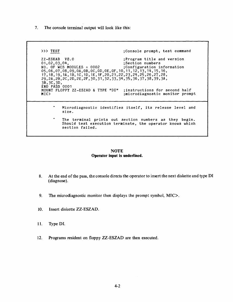
7. The console terminal output will look like this:
>» TEST ;Console prompt, test command
ZZ-ESKAB V8.0 ;Program title and version 01,02,03,04, ~Section numbers NO. OF WCS MODULES = 0002 ;Configuration information 05,06,07,08,09,0A,OB,OC,OD,OE,OF,10,11,12,13,14,15,16, 17, 18, 19, 1A, 1B, 1C, 1D, 1E, 1F ,20,21,22,23,24,25,26,27,28, 29,2A,2B,2C,2D,2E,2F,30,31,32,33,34,35,36,37,38,39,3A, 3B,3C,3D, END PASS 0001 MOUNT FLOPPY ZZ-ESZAD & TYPE "DI" ;instructions for second half MIC> ;microdiagnostic monitor prompt
Microdiagnostic identifies itself, its release level and size.
The terminal prints out section numbers as they begin. Should test execution terminate, the operator knows which section failed.
NOTE Operator input is underlined.
8. At the end of the pass, the console directs the operator to insert the next diskette and type DI (diagnose).
9. The microdiagnostic monitor then displays the prompt symbol, MIC>.
10. Insert diskette ZZ-ESZAD.
11. Type DI.
12. Programs resident on floppy ZZ-ESZAD are then executed.
4-2

13. Console terminal output:
MIC> DI 3E, # MEM CTRLS = 00000001 3F,40, 4K CHIP 00001008 41,42, CPU TR = 00000010 43,44,45,46,47,48,49,4A,4B,4C,4D, CTRL 1 MAX ADR+1 = 00090000 4E, CTRL 1 MAX ADR+1 = 00090000 4F,50, STARTING FPA TESTS 51,52,53,54,55,56,57,58,59,5A,5B,5C END PASS 0001
;diagnose command ;section number(s) ;configuration information ;which is system specific
CPU HALTED, SOMM CLEAR, STEP:NONE, CLOCK:NORM ;CPU status RAD:HEX, ADD=PHYS, DAT:LONG, FILL:OO, REL:OOOOOOOO ;and console !NIT SEQ DONE ;program HALTED AT 00000000 ;defaults
(RELOADING WCS) LOAD DONE, 00003200 BYTES LOADED VER: PCS:01 WCS:03-10 FPLA=03 CON:PX03-08 ;configuration
;information ;console prompt >»
Note that microdiagnostic section numbers are sequential (Hex).
End of pass indication is printed when test execution is completed.
Note that after successful completion of the microdiagnostic program the microdiagnostic monitor returns control to the console program which then reloads wcs.
The console program puts out a prompt character, >>>.
4.3 MICRODIAGNOSTIC ERROR MESSAGES The microdiagnostic program is broken into two parts: hard-core tests (sections 1-1 F) and microtests (go chain) (sections 20-end). Error message formats for the hard-core tests and the microtests differ only slightly.
4-3
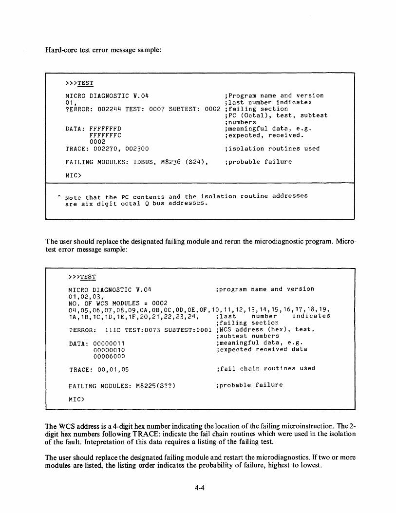
Hard-core test error message sample:
>>>TEST
MICRO DIAGNOSTIC V.04 01, ?ERROR: 002244 TEST: 0007 SUBTEST: 0002
;Program name and version ;last number indicates ;failing section
DATA: FFFFFFFD FFFFFFFC 0002
TRACE: 002270, 002300
FAILING MODULES: IDBUS, M8236 (S24),
MIC>
;PC (Octal), test, subtest ;numbers ;meaningful data, e.g. ;expected, received.
;isolation routines used
;probable failure
A Note that the PC contents and the isolation routine addresses are six digit octal Q bus addresses.
The user should replace the designated failing module and rerun the microdiagnostic program. Microtest error message sample:
>»TEST
MICRO DIAGNOSTIC V.04 01,02,03, NO. OF WCS MODULES = 0002
;program name and version
04, 05, 06, 07, 08, 09, OA, OB, OC, OD, OE, OF, 10, 11 , 12, 13, 14, 15, 16, 17, 18, 19, 1A,1B,1C,1D,1E,1F,20,21,22,23,24, ;last number indicates
;failing section ?ERROR: lllC TEST:0073 SUBTEST:OOOl ;WCS address (hex), test,
DATA: 00000011 00000010 00006000
TRACE: 00,01,05
FAILING MODULES: M8225(S??)
MIC>
;subtest numbers ;meaningful data, e.g. ;expected received data
;fail chain routines used
;probable failure
The WCS address is a 4-digit hex number indicating the location of the failing microinstruction. The 2-digit hex numbers following TRACE: indicate the fail chain routines which were used in the isolation of the fault. Intepretation of this data requires a listing of the failing test.
The user should replace the designated failing module and restart the microdiagnostics. If two or more modules are listed, the listing order indicates the probability of failure, highest to lowest.
4-4

If the failure is still evident after the module identified has been replaced, use the data printed out to further isolate the problem.
4.4 SECTION PARTITIONING The hard-core tests check the console interface, the microsequencer, the WCS and PCS, and part of the data path.
The microtests are partitioned into 9 major categories as follows:
1. Data Path Tests 2. Cache Memory Tests 3. Translation Buffer Tests 4. Instruction Buff er Tests 5. Condition Codes, Interrupts, and Exceptions Tests 6. SBI Interface Tests 7. Memory Tests 8. SBI Device Tests 9. Floating-Point Accelerator Tests
All hard-core tests and microtest categories 1 through 5 are packaged on floppy number 1 (sections 1 through 30) and categories 6 through 9 on floppy number 2 (sections 3E through 5B).
4.5 SBI DEVICE TESTS Category 8 uses any available devices (UBAs or MBAs) that are found on the SBI to test their fault detection logic. Category 8 also uses a UBA (if there is one on the system) to test the cache invalidation logic.
4.6 INTERPRETATION OF WCS, PCS, AND FPLA REVISION STATUS When WCS has been reloaded, the console terminal prints out revision status, for example:
VER: PCS:01 WCS:03-10 FPLA=03 CON:PX03-08
The PCS code refers to the revision number of the programmed control store (ROM). The WCS (writable control store) code contains two numbers. The primary version number (in this case, 03) refers to the FPLA number which is required for this WCS version. The secondary version number (in this case, 10) refers to the version of WCS which has been loaded.
The FPLA (field programmable logic array) code refers to the FPLA chip revision which is currently installed in the VAX-11/780 CPU. This chip causes the microprocessor to retrieve microwords from WCS instead of from PCS when specific locations are addressed.
The CON (console) code refers to the revision number of the console software which has been loaded into the LSI-11 memory.
Two types of mismatch may occur. If the WCS revision does not match the FPLA revision, the console program issues a warning. However, if the WCS revision does not match the PCS revision, the mismatch is fatal.
4-5

CHAPTER 5 USING THE DIAGNOSTIC SUPERVISOR
Most macro level diagnostic programs run in conjunction with the diagnostic supervisor (the hardcore instruction text, EVKAA, is an exception). The supervisor provides a set of commands to the operator which enable him to control the execution of diagnostic programs simply and precisely.
VAX diagnostic release II (August 1979) consists of an enhanced version of the supervisor and matching versions of the diagnostic programs that run with it. This release provides the following new features.
• An improved diagnostic system initial distribution facility. This enables the user to build a diagnostic disk pack on his system device from magnetic tape files at the time of system installation.
• An improved update facility that enables the user to transfer updated diagnostic files from floppy diskettes to the diagnostic system pack in semi-automatic fashion.
• A variety of boot command files to enable the operator to boot the diagnostic supervisor from a number of devices.
• A system profiler that enables the operator to describe the VAX system configuration to the supervisor.
• Support for the LOAD and RUN supervisor commands in the standalone mode.
• Addition of a new supervisor debug feature, the Next command.
• A scripting facility that enables the supervisor to execute command files. Release II includes configuration and system test scripts appropriate for each system. Users can modify these scripts to accommodate add-on equipment, and they can create their own scripts.
• A set of load path floppy diskettes from which to load and run diagnostics if hardware errors prevent conventional loading from the diagnostic system disk pack.
5.1 DIAGNOSTIC SUPERVISOR COMMANDS The diagnostic supervisor commands are grouped in four sets:
Program and test sequence control Scripting features Execution control Debug and utility features
Commands, switches, and literal arguments can be abbreviated to the minimum number of characters necessary to retain their unique identity. For example, the Load command can be specified by a single L, whereas the Start command requires a minimum of ST.
5-1

In the symbolic command descriptions which follow, certain special characters are employed that require some explanation. Angle brackets, < >, are used to enclose symbolic arguments that are satisfied by a numeric expression or character string. Optional arg_uments are enclosed by square brackets, [ ]. An OR function is indicated with an exclamation point, ! . Literal arguments such as ALL, OFF, and FLAGS are capitalized.
Use the hyphen, -, as a continuation character at the end of a line to continue a command from one line to the next. Use an exclamation point, !, to separate a comment from a command in a command line.
Notice that operator input is underlined in the examples that follow.
5.1.1 Program/Test Sequence Control Commands These commands enable the operator to select programs and portions of programs and to control the sequence of test execution.
Set Load Command
SET LOAD <device>:[directory]<CR>
The Set Load command establishes the storage device from which the supervisor will load diagnostic programs. The default load device is the device from which the supervisor was booted. Use Set Load when you wish to load diagnostic programs from a different device. Use the Set Load command in combination with the Load command or the Run command.
Show Load Command
SHOW LOAD<CR>
DS> SET LOAD DMA0: [SYSMAINT] DS> LOAD ESDXA
DS> SET LOAD DMA0: [SYSMAINT] DS> RUN ESDXA
Example 5-1 Set Load Command
NOTE The directory name, and the square brackets around it, are necessary in the Set Load command.
The Show Load command causes the supervisor to display the storage device from which diagnostic programs are to be loaded when the Load command is given.
DS> SHOW LOAD DMA0: [S YSMAINT] DS>
Example 5-2 Show Load Command
5-2

Load Command
LOAD <file-spec> <CR>
This command loads the specified file into main memory from the default load device. The default file extension is .EXE. The storage devi~e from which the program is loaded is the device established on the previous Set Load command. Note that you need supply only the five-letter code that identifies each diagnostic program for the command line argument <file-space>.
LOAD ESTAA
Attach Command
Load the local terminal diagnostic program.
Example 5-3 Load Command
ATTACH <UUT-type> <link-name> <generic-device-name> ... <CR>
The operator must use several Attach commands, before starting a diagnostic program, to define each unit under test (UUT), and the devices that link it to the SBI, for the supervisor. If you are testing several units at once, repeat the Attach command for each device. Every unit under test is uniquely defined by a hardware designation and a link.
The first parameter <UUT-type> is the hardware designation of the unit under test. For example, RH780, TM03, TE16, and DZI I are hardware designations.
The second parameter <link-name> is the name of the piece of hardware that links the unit under test, in most cases through intermediate links, to the main system bus. For example, an RH780 is linked to the SBI; a TU45 is linked to an MTa; and a DZI I is linked to a DWn. You must attach each piece of hardware (with the exception of the SBI) before you can use it as a link in an Attach command.
The third parameter is the generic device name, which identifies to the supervisor the particular unit to be tested. Use the form "GGan" for the device name. "GG" is a 2-character generic device name (alphabetic). "a" is an alphabetic character, specifying the device controller. "n" is a decimal number in the range of 0-255, specifying the number of the unit with respect to the controller.
Use the unit number, "n" or "a", only if it is applicable to the device. You must supply additional information for some types of hardware to enable the diagnostic program to address the device. For example, you must supply the TR and BR numbers for an RH780, the controller number for a TM03, and the CSR, vector, and BR for a Unibus device. If you include such additional information in the Attach command line, use the order and format shown in Table 5-1. If you do not include additional information, but the information is necessary, the supervisor will prompt you for it.
5-3

Table 5-1 Device Naming Conventions
Type Link Generic Additional Information
KA780 SBI KAn <G-floating> <H-floating> <WCS-last-address>
MS780 SBI MSa <tr> RH780 SBI RH a <tr><IJI> DW780 SBI DWa <tr><br> DR780 SBI ??a <tr><br> RP07 RH a DBan RP06 RH a DBan RP05 RH a DBan RP04 RH a DBan RM03 RH a DRan RK611 DWa DMa <ucsr> <uvector> <ubr> RK07 DMa DMan RK06 DMa DMan TM03 RH a MTa <drive> TE16 MTa MTan TU45 MTa MTan TU77 MTa MTan DZl 1 DWa TTa <ucsr> <uvector> <ubr> <EIA>
!<20MA> DUPll DWa XJan <ucsr> <uvector> <ubr> DMCll DWa XMan <ucsr> <uvector> <ubr> KMCll DWa XMan <ucsr> <uvector> <ubr> LPl 1 DWa LP a <ucsr> <uvector> <ubr> CRll DWa CRa <ucsr> <uvector> <ubr> DRllB DWa ??a <ucsr> <uvector> <ubr> PCLll DWa ??a <ucsr> <uvector> <ubr> TS04 Dwa MTan <ucsr> <uvector> <ubr> RL02 ??a ??an RLll Dwa ??a <ucsr> <uvector> <ubr>
The definitions for the additional fields are:
<tr> <br> <drive> <ucsr> <uvector> <ubr>
Adapter TR number Adapter BR level Massbus drive Unibus CSR address Unibus vector Unibus BR level
5-4
decimal decimal decimal octal octal decimal
1-15 4-7 0-7 760000-777776 2-776 4-7
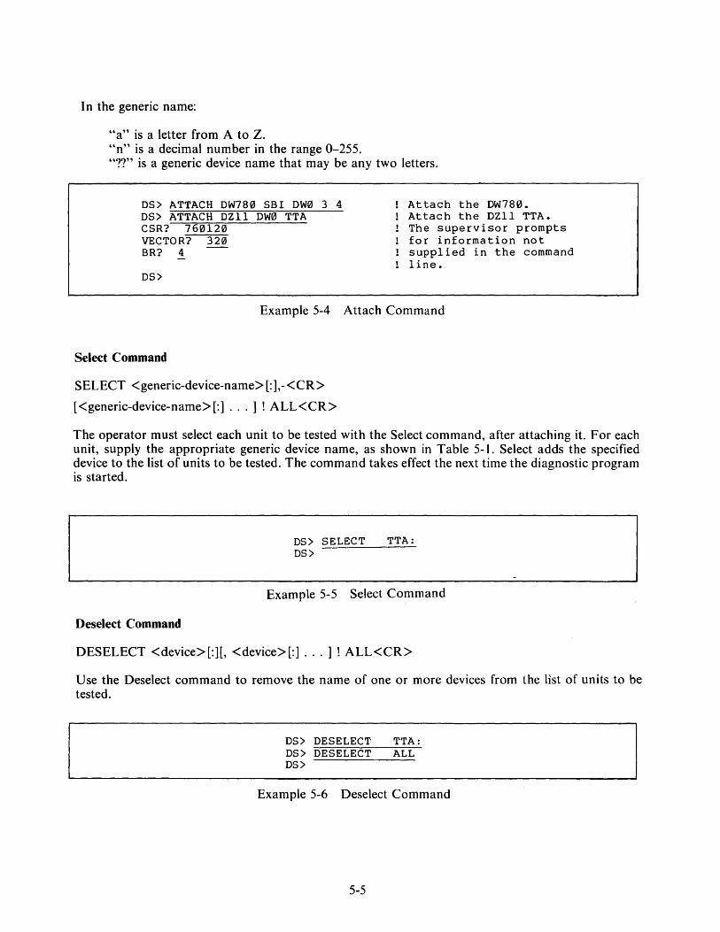
In the generic name:
"a" is a letter from A to Z. "n" is a decimal number in the range 0-255. "??" is a generic device name that may be any two letters.
DS> ATTACH DW780 SBI DW0 3 4 DS> ATTACH DZll DW0 TTA
Attach the DW780. Attach the DZll TTA. The supervisor prompts for information not supplied in the command line.
CSR? 760120 VECTOR? 320 BR? 4
OS>
Example 5-4 Attach Command
Select Command
SELECT <generic-device-name> [:],-<CR>
[<generic-device-name>[:] ... ] ! ALL< CR>
The operator must select each unit to be tested with the Select command, after attaching it. For each unit, supply the appropriate generic device name, as shown in Table 5-1. Select adds the specified device to the list of units to be tested. The command takes effect the next time the diagnostic program is started.
DS> SELECT TTA: DS>
Example 5-5 Select Command
Deselect Command
DESELECT <device>[:][, <device>[:] ... ] ! ALL<CR>
Use the Deselect command to remove the name of one or more devices from the list of units to be tested.
DS> DESELECT TTA: DS> DESELECT ALL DS>
Example 5-6 Deselect Command
5-5
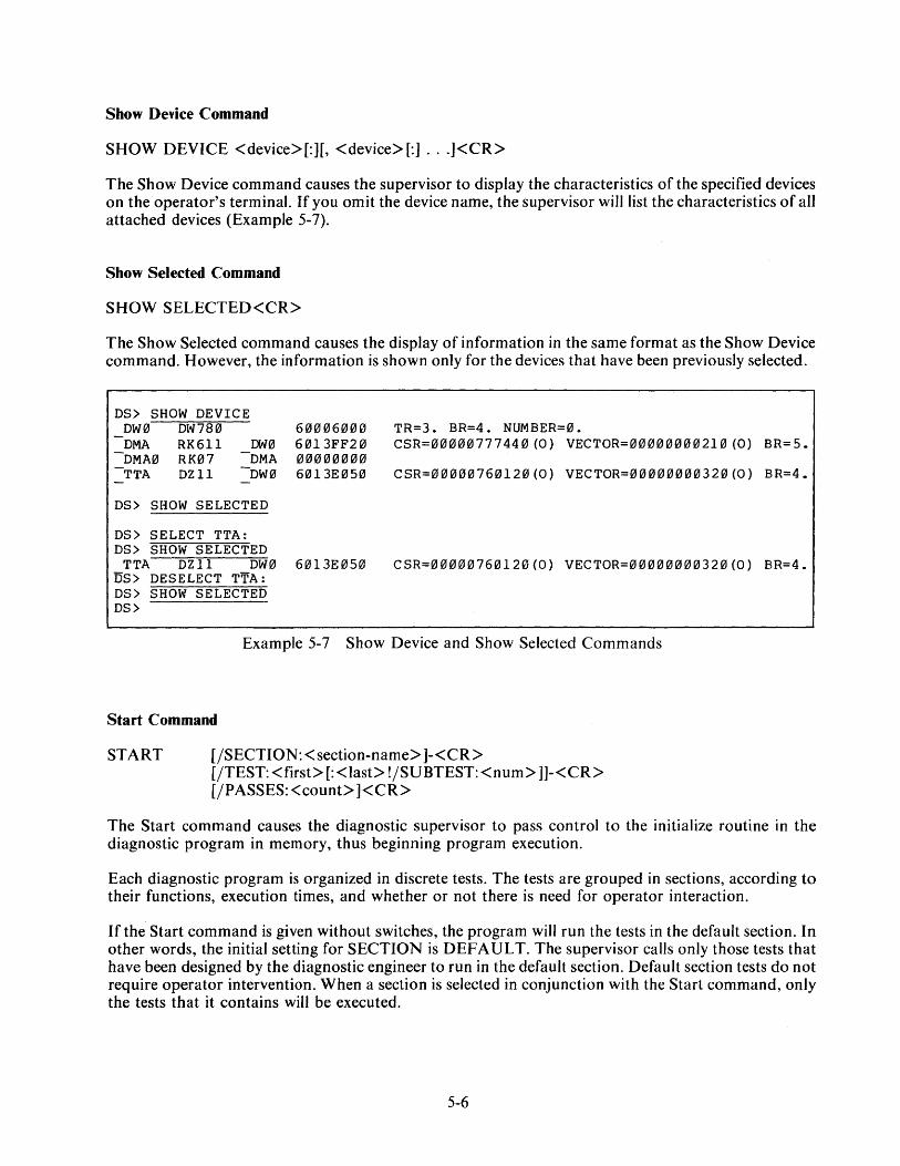
Show Device Command
SHOW DEVICE <device>[:][, <device>[:] ... ]<CR>
The Show Device command causes the supervisor to display the characteristics of the specified devices on the operator's terminal. If you omit the device name, the supervisor will list the characteristics of all attached devices (Example 5-7).
Show Selected Command
SHOW SELECTED<CR>
The Show Selected command causes the display of information in the same format as the Show Device command. However, the information is shown only for the devices that have been previously selected.
DS> SHOW DEVICE DW0 DW780 DMA RK611 DW0
-DMA0 RK07 -DMA -TTA DZll -DW0
DS> SHOW SELECTED
DS> SELECT TTA: DS> SHOW SELECTED
60006000 6013FF20 00000000 6013Ef2J50
TTA DZll DW0 6013E050 DS> DESELECT TTA: DS> SHOW SELECTED DS>
TR=3. BR=4. NUMBER=0. CSR=00000777440(0) VECTOR=00000000210(0) BR=S.
CSR=00000760120(0) VECTOR=00000000320(0) BR=4.
CSR=00000760120(0) VECTOR=00000000320(0) BR=4.
Example 5-7 Show Device and Show Selected Commands
Start Command
START [/SECTION:< section-name> ]-<CR> [/TEST: <first>[: <last> !/SUBTEST: <num> ]]-<CR> [/PASSES:<count> ]<CR>
The Start command causes the diagnostic supervisor to pass control to the initialize routine in the diagnostic program in memory, thus beginning program execution.
Each diagnostic program is organized in discrete tests. The tests are grouped in sections, according to their functions, execution times, and whether or not there is need for operator interaction.
If the Start command is given without switches, the program wiIJ run the tests in the default section. In other words, the initial setting for SECTION is DEFAULT. The supervisor calls only those tests that have been designed by the diagnostic engineer to run in the default section. Default section tests do not require operator intervention. When a section is selected in conjunction with the Start command, only the tests that it contains will be executed.
5-6

The TEST switch is used in two distinctly different ways. If the first and last arguments are specified, the supervisor sequentially passes control to tests.first through last, inclusively. If the.first argument is combined with the SUBTEST switch, program execution begins at the beginning of the first test and terminates at the end of the subtest num. If the SUBTEST switch is used in conjunction with the PASSES switch, the operator is provided with a loop-on-subtest capability. In this case, only the subtest named in the command line is executed, once looping begins.
If the TEST switch is not specified, all tests within the named section of the program are executed. In other words, the default for TEST is TEST a through TEST n, where TEST n is the highest numbered test in the section. If only the first argument is specified with the TEST switch, the last argument is assumed by default to be the highest numbered test within the selected section of the program.
Tests are run only if they are included in the section named. If the PASSES switch is not used, the default value is 1. Test and pass numbers are decimal. The minimum value for passes is I. The maximum value is 0, which means infinity in this context.
For example:
DS> START
DS> START/SEC:MANUAL
DS> START/SEC:MANUAL/TEST:32:33
DS> START/TEST:6:12
DS> START/TEST:9/SUBTEST:5
DS> START/TEST:9
DS> START/PASS:3
DS> START/TEST:9/SUBTEST:5/PASS:0
Start execution of the diagnostic program in memory.
Start execution of the manual section of the program.
Run tests 32 and 33 if they are in the manual section. Some tests may not be executed unless the section is specified.
Run tests 6, 7, 8, 9, 10, 11, 12.
Run test 9, subtests 1, 2, 3, 4, 5.
Run tests 9 through n, where n is the last test in the default section.
Run 3 passes of the default section.
Execute test 9, subtests 1,2,3,4, and then loop on subtest 5 indefinitely.
Example 5-8 Start Command
5-7

Run Command
RUN <file-spec> (/SECTION: <section name> ]-<CR> [/TEST:<first>[:<last> !/SUBTEST:<num> ]]-<CR> [/PASSES:<count> ]<CR>
Run is equivalent to a Load and Start command sequence. The Run command switches are identical to those in the Start command.
For example:
DS> RUN ESTAA
DS> RUN ESTAA/SEC:MANUAL
DS> RUN ESTAA/SEC:MANUAL/TEST:32:33
DS> RUN ESTAA/TEST:6:12
DS> RUN ESTAA/TEST:9/SUBTEST:5
DS> RUN ESTAA/TEST:9
DS> RUN ESTAA/PASS:3
DS> RUN ESTAA/TEST:9/SUBTEST:5/PASS:0
Load and run the local terminal diagnostic.
Load the local terminal diagnostic and run the manual section.
Load the local terminal diagnostic and run tests 32 and 33 in the manual section.
Load the local terminal diagnostic and run tests 6, 7, 8, 9, 10, 11, 12.
Load the local terminal diagnostic and run test 9, s ub t e st s 1 , 2 , 3 , 4 , 5 •
Load the local terminal diagnostic and run tests 9 through n, where n is the last test in the default section.
Load the local terminal diagnostic and run three passes.
Load the local terminal diagnostic, execute test 9, subtests 1,2,3,4, and then loop on test 9, subtest 5 ind e finite 1 y.
Example 5-9 Run Command
5-8

Summary Command
SUMMARY<CR>
This command causes the execution of the program's summary report code section, which prints statistical reports. Note that this command is generally used only after running a pass of a diagnostic program. However, the summary command can be used at any time, and would be useful, for example, when the Disk Reliability Program is run. Type Control C first to return control to the command line interpreter (CLI). Then type SUMMARY to obtain a statistical report on the program. CONTINUE may be typed at this point, if the operator wishes to resume program execution.
Control C
Normally Control C returns control from a diagnostic program to the command line interpreter in the diagnostic supervisor. The supervisor then enters a command wait state and displays the DS> prompt on the operator's terminal. The operator may then issue any valid command. Control C is the only diagnostic supervisor command that may be issued while a program is running. When a diagnostic program is running in conversation mode, Control C returns control to a command interpreter within the program for the conversation mode.
Continue Command
CONTINUE< CR>
This command causes program execution to resume at the point at which the program was suspended. This command is used to proceed from a breakpoint, error halt, summary, or Control C situation.
The following example shows how Control C, Summary, and Continue can be used together to obtain statistics on the ·program being run and to then resume execution .
"C DS> SUMMARY
DS> CONTINUE
•.• Program is running •••
Statistical Report
Operator types Control C. Supervisor prompt. Operator requests statistical report.
Supervisor prompt. Operator requests resumption of program •
• • • Program is running ••.
Example 5-10 Use of Control C, Summary, and Continue Commands
5-9
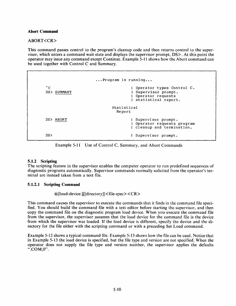
Abort Command
ABORT<CR>
This command passes control to the program's cleanup code and then returns control to the supervisor, which enters a command wait stafe and displays the supervisor prompt, DS>. At this point the operator may issue any command except Continue. Example 5-11 shows how the Abort command can be used together with Control C and Summary .
"c DS> SUMMARY
••• Program is running •••
Operator types Control C. Supervisor prompt. Operator requests statistical report.
Statistical Report
DS> ABORT Supervisor prompt. Operator requests program cleanup and termination.
DS> Supervisor prompt.
Example 5-11 Use of Control C, Summary, and Abort Commands
5.1.2 Scripting The scripting feature in the supervisor enables the computer operator to run predefined sequences of diagnostic programs automatically. Supervisor commands normally solicited from the operator's terminal are instead taken from a text file.
5.1.2.1 Scripting Command
@[load-device:] [[directory]]< file-spec>< CR>
This command causes the supervisor to execute the commands that it finds in the command file specified. You should build the command file with a text editor before starting the supervisor, and then copy the command file on the diagnostic program load device. When you execute the command file from the supervisor, the supervisor assumes that the load device for the command file is the device from which the supervisor was loaded. If the load device is different, specify the device and the directory for the file either with the scripting command or with a preceding Set Load command.
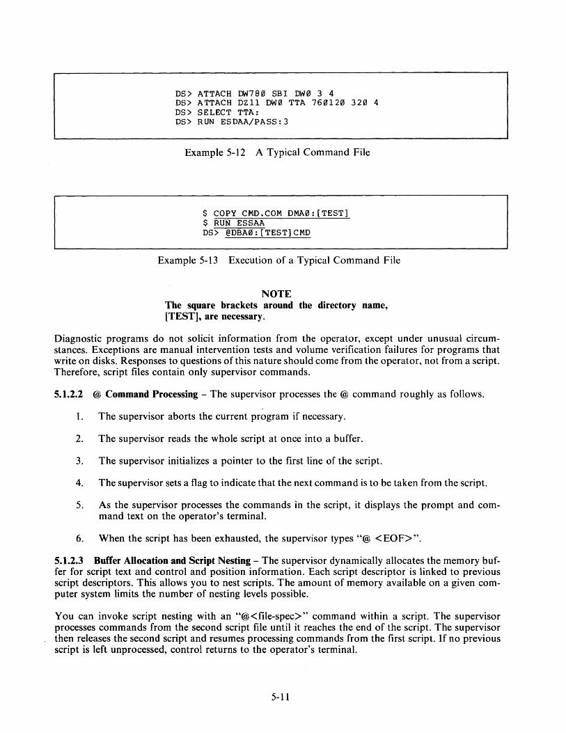
Example 5-12 shows a typical command file. Example 5-13 shows how the file can be used. Notice that in Example 5-13 the load device is specified, but the file type and version are not specified. When the operator does not supply the file type and version number, the supervisor applies the defaults ".COM;O".
5-10
DS> ATTACH DW780 SB! DW0 3 4 DS> ATTACH DZll DW0 TTA 760120 320 4 DS> SELECT TTA: DS> RUN ESDAA/PASS:3
Example 5-12 A Typical Command File
$ COPY CMD.COM DMA0: [TEST] $ RUN ESSAA DS> @DBA0:[TEST]CMD
Example 5-13 Execution of a Typical Command File
NOTE The square brackets around the directory name, [TEST], are necessary.
Diagnostic programs do not solicit information from the operator, except under unusual circumstances. Exceptions are manual intervention tests and volume verification failures for programs that write on disks. Responses to questions of this nature should come from the operator, not from a script. Therefore, script files contain only supervisor commands.
5.1.2.2 @ Command Processing - The supervisor processes the @ command roughly as follows.
1. The supervisor aborts the current program if necessary.
2. The supervisor reads the whole script at once into a buffer.
3. The supervisor initializes a pointer to the first line of the script.
4. The supervisor sets a flag to indicate that the next command is to be taken from the script.
5. As the supervisor processes the commands in the script, it displays the prompt and command text on the operator's terminal.
6. When the script has been exhausted, the supervisor types"@ <EOF>".
5.1.2.3 Buffer Allocation and Script Nesting - The supervisor dynamically allocates the memory buffer for script text and control and position information. Each script descriptor is linked to previous script descriptors. This allows you to nest scripts. The amount of memory available on a given computer system limits the number of nesting levels possible.
You can invoke script nesting with an "@<file-spec>" command within a script. The supervisor processes commands from the second script file until it reaches the end of the script. The supervisor then releases the second script and resumes processing commands from the first script. If no previous script is left unprocessed, control returns to the operator's terminal.
5-11

5.1.2.4 Interrupting the Script - The operator may type Control C on the terminal to interrupt the script, if necessary. Control C causes the supervisor to suspend the script and stop the current program, if a program is running. The operator can issue any command while the script is suspended. However, if the operator wants to resume the script, eventually, by typing CONTINUE, the selection of commands is limited.
These commands can be followed by resumption of the program.
SET CLEAR EXAMINE DEPOSIT SHOW SUMMARY NEXT CONTINUE
The following commands flush all scripts and return control to the command line interpreter in the supervisor:
ATTACH SELECT DESELECT LOAD START RUN ABORT
In general, a command flushes scripts if it would be meaningless to continue the script after the command has been executed.
5.1.2.5 Command File Format - A command procedure must be a contiguous ASCII file created by VAX-11 RMS (record management services) on an ODS-1 or ODS-2 disk file structure. The file must be line oriented and records must not exceed 72 characters. You can create a command procedure file with any editor or with the VMS CREA TE command. The supervisor treats all records as supervisor commands. Any legitimate supervisor command is valid in a script.
5.1.3 Execution Control Functions The execution control functions allow the operator to alter the characteristics of the diagnostic programs and the diagnostic supervisor. These functions are implemented by command flags and event flags. The command flags are used to control the printing of error messages, ringing the bell, and halting and looping of the program.
Set Flags Command
SET [FLAGS] <arg-list><CR>
This command results in the setting of the execution control flags specified by arg-list. No other flags are affected. Arg-list is a string of flag mnemonics from the following table, separated by commas.
HALT Halt on error detection. When the program detects a failure and this flag is set, the supervisor enters a command wait state after all error messages associated with the failure have been output. The operator may then continue, restart, or abort the program. This flag takes precedence over the LOOP flag.
5-12

LOOP
BELL
IEI
IE2
IE3
JES
QUICK
TRACE
OPERATOR
PROMPT
ALL
Loop on error. When set, this flag causes the program to enter a predetermined scope loop on a test or subtest that detects a failure. Set the IE I flag if you want to inhibit error messages. Looping will continue until the operator returns control to the supervisor by using the Control C command. The operator may then continue, clear the flag and continue, or abort the program.
Bell on error. When set, this flag causes the supervisor to send a bell to the operator whenever the program detects a failure.
Inhibit error messages at level 1. When set, this flag suppresses all error messages, except those that are forced by the program or supervisor.
Inhibit error messages at level 2. When set, this flag suppresses basic and extended information concerning the failure. Only the header information message (first three lines) is output for each failure.
Inhibit error messages at level 3. When set, this flag suppresses extended information concerning the failure. The header and basic information messages are output for each failure.
Inhibit summary report. When set, this flag suppresses statistical report messages.
Quick verify. When set, this flag indicates to the program that the operator wants a quick verify mode of operation. The interpretation of this flag is program dependent.
Report the execution of each test. When set, this flag causes the supervisor to report the execution of each individual test within the program as the supervisor dispatches control to that test.
Operator present. When set, this flag indicates to the supervisor that operator interaction is possible. When cleared, the supervisor takes appropriate actions to ensure that the test session continues without an operator.
Display long dialogue. When set, this flag indicates to the supervisor that the operator wants to see the limits and defaults for all questions printed by the program.
All flags in this list.
Clear Flags Command
CLEAR [FLAGS] <arg-list> <CR>
This command results in the clearing of the flags specified by arg-list. No other flags are affected. A rg-list is a string of flag mnemonics separated by commas. See the SET command for supported arguments.
Set Flags Default Command
SET FLAGS DEFAULT<CR>
This command returns all flags to their initial default status. The default flag settings are OPERATOR and PROMPT.
5-13
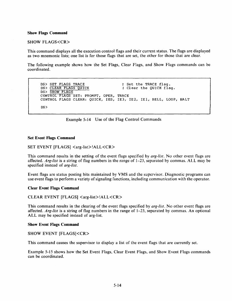
Show Flags Command
SHOW FLAGS<CR>
This command displays all the execution control flags and their current status. The flags are displayed as two mnemonic lists; one list is for those flags that are set, the other for those that are clear.
The following example shows how the Set Flags, Clear Flags, and Show Flags commands can be coordinated.
DS> SET FLAGS TRACE ! Set the TRACE flag. DS> CLEAR FLAGS QUICK ! Clear the QUICK flag. DS> SHOW FLAGS CONTROL FLAGS SET: PROMPT, OPER, TRACE CONTROL FLAGS CLEAR: QUICK, !ES, IE3, IE2, !El, BELL, LOOP, HALT
DS>
Example 5-14 Use of the Flag Control Commands
Set Event Flags Command
SET EVENT [FLAGS] <arg-list> !ALL< CR>
This command results in the setting of the event flags specified by arg-list. No other event flags are affected. Arg-list is a string of flag numbers in the range of 1-23, separated by commas. ALL may be specified instead of arg-list.
Event flags are status posting bits maintained by VMS and the supervisor. Diagnostic programs can use event flags to perform a variety of signaling functions, including communication with the operator.
Clear Event Flags Command
CLEAR EVENT [FLAGS] <arg-list> !ALL<CR>
This command results in the clearing of the event flags specified by arg-list. No other event flags are affected. Arg-list is a string of flag numbers in the range of 1-23, separated by commas. An optional ALL may be specified instead of arg-list.
Show Event Flags Command
SHOW EVENT [FLAGS]<CR>
This command causes the supervisor to display a list of the event flags that are currently set.
Example 5-15 shows how the Set Event Flags, Clear Event Flags, and Show Event Flags commands can be coordinated.
5-14

DS> SET EVENT FLAGS 1, 9, 15 DS> CLEAR EVENT FLAGS 2, 6 DS> SHOW EVENT fLAGS EVENT FLAGS SET: 15, 9, 1 DS>
Example 5-15 Event Flags Control Commands
5.1.4 Debug and Utility Commands This group of commands provides the operator with the ability to isolate errors and to alter diagnostic program code. The supervisor allows up to 15 simultaneous breakpoints within the program. The operator can also examine and/or modify the program image in memory.
Set Base Command
SET BASE <address><CR>
This command loads the address specified into a software register. This number is then used as a base to which the address specified in the Set Breakpoint, Clear Breakpoint, Examine, and Deposit commands is added. The Set Base command is useful when referencing code in the diagnostic program listings. The base should be set to the base address (see the program link map) of the program section referenced. Then the PC numbers provided in the listings can be used directly in referencing locations in the program sections (Example 5-16).
For example:
DS> SET BASE E00
DS>
Set the base address to the beginning of the psect of the routine under examination.
Example 5-16 Set Base Command
NOTE Virtual address = physical address (normally) when memory management is turned off.
Set Breakpoint Command
SET BREAKPOINT <address><CR>
This command causes control to pass to the supervisor when the program counter points to the <address> previously specified by this command. A maximum of 15 simultaneous breakpoints can be set within the diagnostic program.
5-15
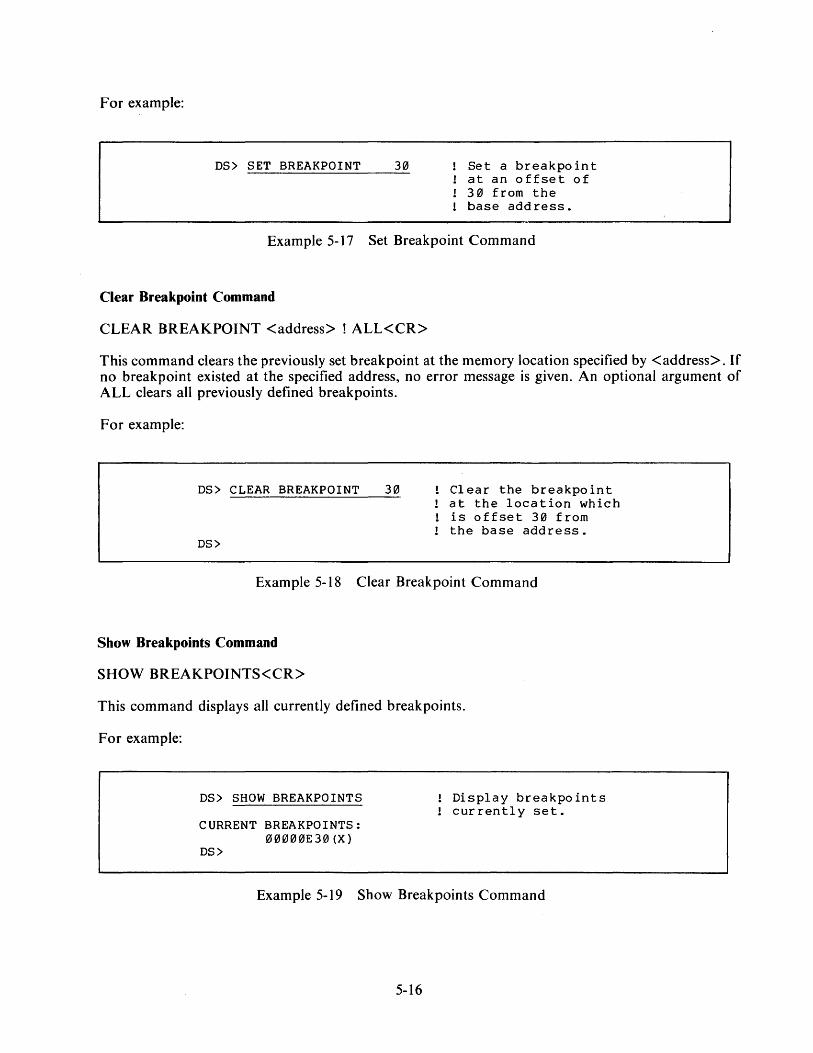
For example:
DS> SET BREAKPOINT 30 Set a breakpoint at an offset of 3 0 from the base address.
Example 5-17 Set Breakpoint Command
Clear Breakpoint Command
CLEAR BREAKPOINT <address> ! ALL<CR>
This command clears the previously set breakpoint at the memory location specified by <address>. If no breakpoint existed at the specified address, no error message is given. An optional argument of ALL clears all previously defined breakpoints.
For example:
DS> CLEAR BREAKPOINT
DS>
30 Clear the breakpoint at the location which is offset 30 from the base address.
Example 5-18 Clear Breakpoint Command
Show Breakpoints Command
SHOW BREAKPOINTS<CR>
This command displays all currently defined breakpoints.
For example:
DS> SHOW BREAKPOINTS
CURRENT BREAKPOINTS: 00000E30(X)
DS>
Display breakpoints currently set.
Example 5-19 Show Breakpoints Command
5-16
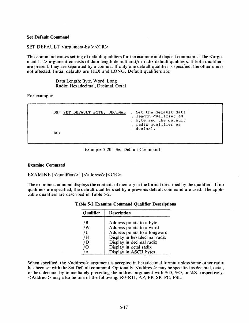
Set Default Command
SET DEFAULT <argument-list><CR>
This command causes setting of default qualifiers for the examine and deposit commands. The <argument-list> argument consists of data length default and/or radix default qualifiers. If both qualifiers are present, they are separated by a comma. If only one default qualifier is specified, the other one is not affected. Initial defaults are HEX and LONG. Default qualifiers are:
For example:
Data Length: Byte, Word, Long Radix: Hexadecimal, Decimal, Octal
DS> SET DEFAULT BYTE, DECIMAL
DS>
Set the default data length qualifier as byte and the default radix qualifier as decimal.
Example 5-20 Set Default Command
Examine Command
EXAMINE [<qualifiers>] [<address> ]<CR>
The examine command displays the contents of memory in the format described by the qualifiers. If no qualifiers are specified, the default qualifiers set by a previous default command are used. The applicable qualifiers are described in Table 5-2.
Table 5-2 Examine Command Qualifier Descriptions
Qualifier
/B /W /L /H /D /0 /A
Description
Address points to a byte Address points to a word Address points to a longword Display in hexadecimal radix Display in decimal radix Display in octal radix Display in ASCII bytes
When specified, the <address> argument is accepted in hexadecimal format unless some other radix has been set with the Set Default command. Optionally, <address> may be specified as decimal, octal, or hexadecimal by immediately preceding the address argument with %D, %0, or %X, respectively. <Address> may also be one of the following: RO-R 11, AP, FP, SP, PC, PSL.
5-17

For example:
DS> EXAMINE 30
00000E312J: D0513D01 DS>
Display the contents of the longword which is offset 30 from the base address of E00.
Example 5-21 Examine Command
Deposit Command
DEPOSIT [<qualifiers>] <address> <data><CR>
This command accepts data and writes it into the memory location specified by <address> in the format described by the qualifiers. If no qualifiers are specified, the default qualifiers are used. The applicable qualifiers are identical to those of the Examine command described in Table 5-2.
The <address> argument is accepted in hexadecimal format unless some other radix has been set with the Set Default command. Optionally, <address> may be specified as decimal, octal, or hexadecimal by immediately preceding <address> with %D, %0, or %X, respectively.
For example:
DS> DEPOSIT/W/H 30 0001
00012J0E30: 0001 DS>
De po s i t 0 0 01 (hex) in the word off set 3 0 from the base address.
Example 5-22 Deposit Command
Next Command
NEXT [number-of-instructions]<CR>
This command causes the supervisor to execute one macro instruction. If you specify a number ( decimal) after NEXT, the supervisor will execute that number of macro instructions. The supervisor displays the PC of the next instruction and the contents of the next four bytes, after execution of each instruction.
Use this command to step through an area of a program where you suspect a problem. Do not use the Next command unless you have stopped the program at a breakpoint.
5-18

For example:
DS> NEXT 00000E31: 00513001 DS>
Execute the next instruction.
Example 5-23 Next Command
5.2 SIMPLIFIED SYSTEM TESTING
5.2.1 Booting the Supervisor from the System Disk: On-Line Mode When you wish to run diagnostic programs in the on-line mode, first type RUN [SYSMAINT]ESSAA to load and start the diagnostic supervisor.
Terminal output:
$ RUN [SYSMAINT]ESSAA DS>
Example 5-24 Booting the Supervisor On-Line
The supervisor is loaded and started. It prompts the operator with DS>.
5.2.2 Booting the Supervisor from the System Disk: Standalone Mode The VAX console takes a three-character argument with the boot command. These three characters form the name of an indirect command file. The LSI-I I processor in the console ·reads the file selected from the floppy diskette and then executes the file to boot the diagnostic supervisor.
The console floppy diskette (ZZ-ESZAB) contains 27 boot command files. There is one automatic boot file for each possible drive number (0 through 7) on each of the three disk types currently supported on the VAX-I I /780, making 24 automatic files for booting the supervisor from the SYSMAINT directory on the system device. There are three prompting files (one for each drive type) for booting the supervisor from a disk that is not the system device or from a directory other than SYSMAINT. These three files prompt the operator twice, once for the name of the boot file (e.g., DIAGBOOT.EXE) and once for the name of the file to be booted (e.g., ESSAA.EXE). If you use either of those three files, deposit in R3 the number of the disk drive containing the supervisor file, as shown in Example 5-25, before typing the Boot command.
»>DEPOSIT R3 0
Example 5-25 Preparation of R3 for ~ Prompting Boot File
5-I9
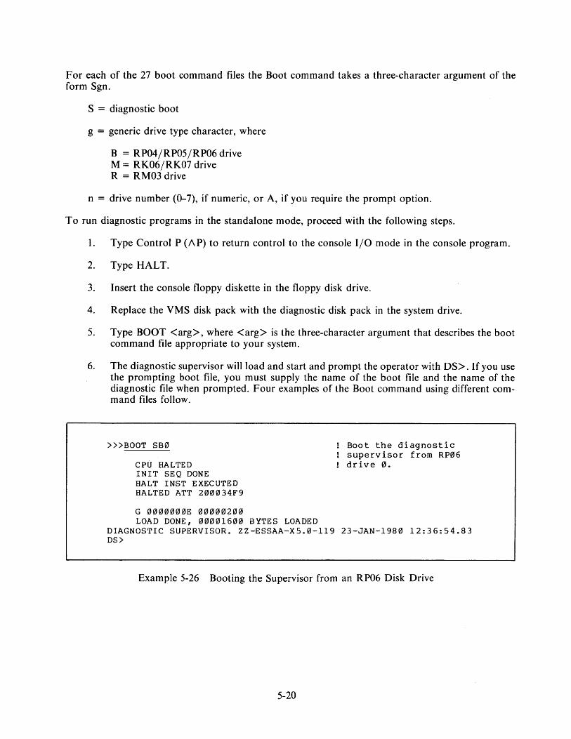
For each of the 27 boot command files the Boot command takes a three-character argument of the form Sgn.
S = diagnostic boot
g = generic drive type character, where
B = RP04/RP05/RP06 drive M = RK06/RK07 drive R = RM03 drive
n = drive number (0-7), if numeric, or A, if you require the prompt option.
To run diagnostic programs in the standalone mode, proceed with the following steps.
I. Type Control P (/\P) to return control to the console 1/0 mode in the console program.
2. Type HALT.
3. Insert the console floppy diskette in the floppy disk drive.
4. Replace the VMS disk pack with the diagnostic disk pack in the system drive.
5. Type BOOT <arg>, where <arg> is the three-character argument that describes the boot command file appropriate to your system.
6. The diagnostic supervisor will load and start and prompt the operator with OS>. If you use the prompting boot file, you must supply the name of the boot file and the name of the diagnostic file when prompted. Four examples of the Boot command using different command files follow.
»>BOOT SB0
CPU HALTED !NIT SEQ DONE HALT INST EXECUTED HALTED ATT 200034F9
G 0000000E 00000200 LOAD DONE, 00001600 BYTES LOADED
Boot the diagnostic supervisor from RP06 drive 0.
DIAGNOSTIC SUPERVISOR. ZZ-ESSAA-XS.0-119 23-JAN-1980 12:36:54.83 DS>
Example 5-26 Booting the Supervisor from an RP06 Disk Drive
5-20
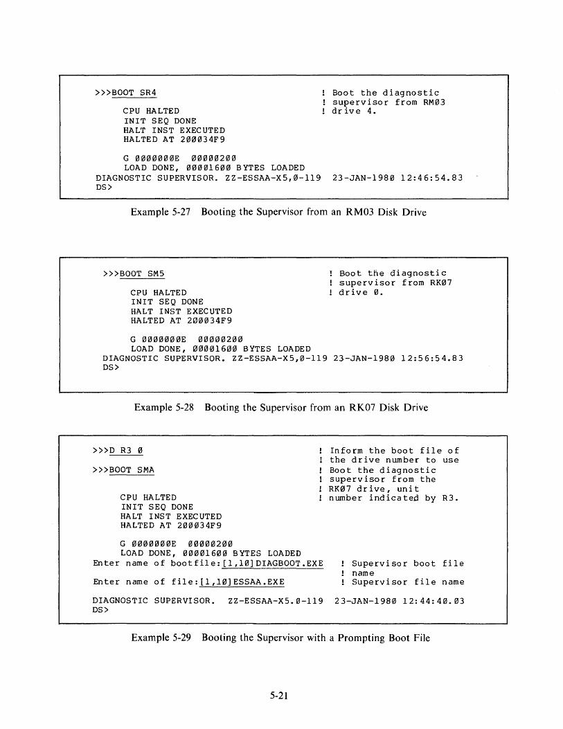
»>BOOT SR4
CPU HALTED INIT SEQ DONE HALT INST EXECUTED HALTED AT 200034F9
G 0000000E 00000200 LOAD DONE, 00001600 BYTES LOADED
DIAGNOSTIC SUPERVISOR. ZZ-ESSAA-XS,0-119 DS>
Boot the diagnostic supervisor from RM03 drive 4.
23-JAN-1980 12:46:54.83
Example 5-27 Booting the Supervisor from an RM03 Disk Drive
>»BOOT SM5
CPU HALTED !NIT SEQ DONE HALT INST EXECUTED HALTED AT 200034F9
G 0000000E 00000200 LOAD DONE, 00001600 BYTES LOADED
Boot the diagnostic supervisor from RK07 drive 0.
DIAGNOSTIC SUPERVISOR. ZZ-ESSAA-XS,0-119 23-JAN-1980 12:56:54.83 DS>
Example 5-28 Booting the Supervisor from an RK07 Disk Drive
»>D R3 0
»>BOOT SMA
CPU HALTED INIT SEQ DONE HALT INST EXECUTED HALTED AT 200034F9
G 0000000E 00000200 LOAD DONE, 00001600 BYTES LOADED
Enter name of bootfile:[l,10]DIAGBOOT.EXE
Enter name of file:[l,10]ESSAA.EXE
Inform the boot file of the drive number to use Boot the diagnostic supervisor from the RK07 drive, unit number indicated by R3.
Supervisor boot file name Supervisor file name
DIAGNOSTIC SUPERVISOR. ZZ-ESSAA-XS.0-119 23-JAN-1980 12:44:40.03 DS>
Example 5-29 Booting the Supervisor with a Prompting Boot File
5-21
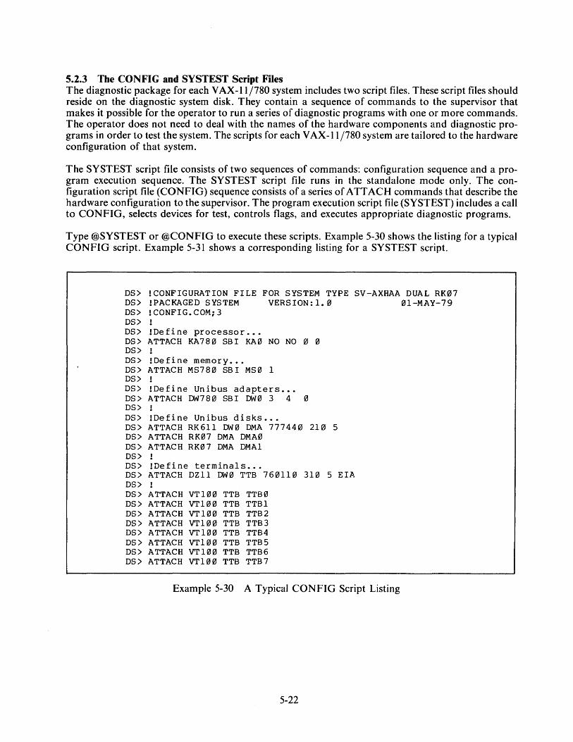
5.2.3 The CONFIG and SYSTEST Script Files The diagnostic package for each VAX-11/780 system includes two script files. These script files should reside on the diagnostic system disk. They contain a sequence of commands to the supervisor that makes it possible for the operator to run a series of diagnostic programs with one or more commands. The operator does not need to deal with the names of the hardware components and diagnostic programs in order to test the system. The scripts for each VAX- l 1 /780 system are tailored to the hardware configuration of that system.
The SYSTEST script file consists of two sequences of commands: configuration sequence and a program execution sequence. The SY ST EST script file runs in the standalone mode only. The configuration script file (CONFIG) sequence consists of a series of ATTACH commands that describe the hardware configuration to the supervisor. The program execution script file (SYSTEST) includes a call to CONFIG, selects devices for test, controls flags, and executes appropriate diagnostic programs.
Type @SYSTEST or @CONFIG to execute these scripts. Example 5-30 shows the listing for a typical CONFIG script. Example 5-31 shows a corresponding listing for a SYSTEST script.
DS> !CONFIGURATION FILE FOR SYSTEM TYPE SV-AXHAA DUAL RK07 DS> !PACKAGED SYSTEM VERSION:l.0 01-MAY-79 DS> !CONFIG.COM;3 DS> DS> !Define processor ••• DS> ATTACH KA780 SBI KA0 NO NO 0 0 DS> DS> !Define memory ... DS> ATTACH MS780 SB! MS0 1 DS> DS> !Define Unibus adapters .•. DS> ATTACH DW780 SB! DW0 3 4 0 DS> DS> !Define Unibus disks .•. DS> ATTACH RK611 DW0 DMA 777440 210 5 DS> ATTACH RK07 DMA DMA0 DS> ATTACH RK07 DMA DMAl DS> DS> !Define terminals ..• DS> ATTACH DZll DW0 TTB 760110 310 5 EIA DS> DS> DS> DS> DS> DS> DS> DS> DS>
ATTACH VT100 TTB TTB0 ATTACH VT100 TTB TTBl ATTACH VT100 TTB TTB2 ATTACH VT100 TTB TTB3 ATTACH VT100 TTB TTB4 ATTACH VT100 TTB TTB5 ATTACH VT100 TTB TTB6 ATTACH VT100 TTB TTB7
Example 5-30 A Typical CONFIG Script Listing
5-22

DS> !SYSTEM TEST SCRIPT FOR SYSTEM TYPE SV-AXHHA DUAL RK07 DS> !PACKAGED SYSTEM DS> !FOR STANDALONE USE ONLY .•• DS> !SYSTEST.COM;3 VERSION:l.0 01-MAY-79 DS> @CONFIG DS> DS> SELECT ALL DS> DS> RUN ESKAX DS> RUN ESKAY DS> RUN ESKAZ DS> DS> RUN ESCBA DS> DS> RUN ESRAA /SEC:QUAL DS> RUN ESDAA /SEC:QUAL DS> DS> RUN ESXBA DS> DS> SET FLAGS QUICK DS> RUN ESRAA DS> CLEAR FLAGS QUICK DS> DS> !END OF SYSTEST ...
Select everything.
Cluster Exerciser Quick Verify. Cluster Exerciser Native Mode Inst. Cluster Exerciser MEM-MGT/PDP-11 Inst.
DW780 Test
Verify disk functionality. Verify DZll functionality.
Verify integrity of system buses.
Run disk reliability in quick mode.
Example 5-31 A Typical SYSTEST Script Listing
If you wish to run a different set of diagnostic programs from those called in the SYSTEST script, type @CONFIG to describe the system configuration to the supervisor before selecting the units for test and running programs.
5.2.4 Modifying Script Files Use the SOS editor under VMS to modify your script file or create new scripts. The file names for the existing script files are shown below.
[SYSMAINT]CONFIG.COM [SYSMAINT]SYSTEST. COM
5.3 RUNNING LOAD PATH DIAGNOSTICS FROM THE FLOPPY: STANDALONE It may be that you cannot boot the diagnostic supervisor from the system disk because of a hardware problem in the load path or on the system disk drive. In this case, boot the supervisor as follows.
1. Type Control P. 2. Type HALT. 3. Insert the load path floppy diskette. 4. Type BOOT.
When the supervisor starts and gives the DS> prompt, type in the commands necessary to define the load path and disk to the supervisor with the ATTACH command. Then select the disk (or other device) to be tested and run the appropriate program. The load path floppy diskette set contains the following program types and classes.
5-23
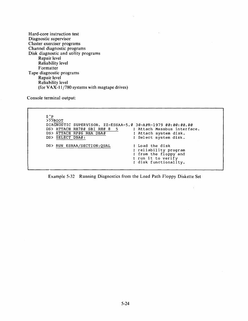
Hard-core instruction test Diagnostic supervisor Cluster exerciser programs Channel diagnostic programs Disk diagnostic and utility programs
Repair level Reliability level Formatter
Tape diagnostic programs Repair level Reliability level (for VAX-11/780 systems with magtape drives)
Console terminal output:
$"P >>5"BOOT DIAGNOSTIC SUPERVISOR. ZZ-ESSAA-5.0 30-APR-1979 00:00:00.00 DS> ATTACH RH780 SBI RH0 8 5 Attach Massbus interface. DS> ATTACH RP06 RHA DBA0 Attach system disk. DS> SELECT DBA0: Select system disk.
DS> RUN ESRAA/SECTION:QUAL Load the disk reliability program from the floppy and run it to verify disk functionality.
Example 5-32 Running Diagnostics from the Load Path FJoppy Diskette Set
5-24

CHAPTER 6 BUILDING AND MAINTAINING THE DIAGNOSTIC SYSTEM DISK
6.1 BUILDING A DIAGNOSTIC DISK PACK Each VAX-11/780 system requires a diagnostic disk pack as well as a VMS disk pack, or a combination VMS and diagnostic disk pack, for proper system operation.
DIGITAL distributes diagnostic system installation kits for VAX-11/780 systems in two package types. RK07 based V AX-11 /780 systems are shipped with RK07 disk packs, which already contain the diagnostic files. RP06 and RM03 based V AX-11 /780 systems are shipped with a magnetic tape containing the diagnostic files.
6.1.1 Dual RP06 and Dual RM03 Based System For dual RP06 and dual RM03 based systems, you must transfer the files on magnetic tape to a formatted disk pack on the system disk drive before you can run many of the macro level diagnostic programs. Build the diagnostic disk pack according to the following procedures.
1. Return control to the console 1/0 mode in the console program by one of the following two methods.
a. Type Control P (/\P) and HALT on the console terminal,
or
b. Place the console floppy disk in the floppy disk drive and cycle the DC ON/OFF switch on the LSI-11 control panel first OFF and then ON.
2. When the console program displays the prompt symbol, > > >, locate the DSC 1 floppy disk, ZZ-ESZEE, and insert it in the floppy disk drive.
3. Mount the diagnostic distribution kit magnetic tape on tape drive 0 with the write-enable ring removed. Ensure that the tape is on-line and positioned at BOT.
4. Mount a formatted scratch disk pack in disk drive 0 and ready the drive for 1/0. Type BOOT. If the system is RP06 based, follow Steps 5 and 6. If the system is RM03 based, follow Step 7.
5. For an RP06, obtain the list of bad blocks from the pack test data supplied by the manufacturer. The list identifies each bad block by cylinder, track, and sector coordinates. Convert this data to logical block numbers (LBN) using the following formula:
LBN = (cylinder * 19 + track) * 22 + sector
You may run the READ ALL section of the disk formatter program (ES RAC) before starting the DSC process as an alternative. The disk formatter program will provide you with the logical block numbers of the bad blocks on the disk pack.
6. In response to the DSC> prompt on the console terminal, type the following command to create and verify the RP06 diagnostic disk.
6-1
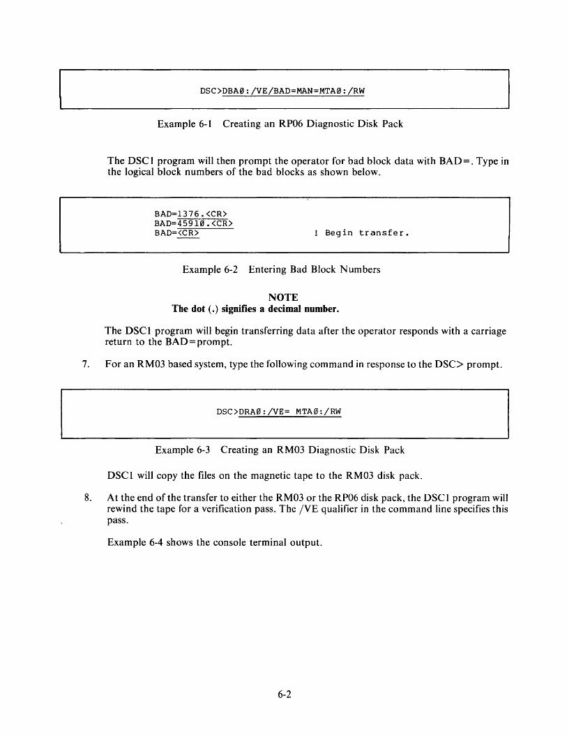
DSC>DBA0:/VE/BAD=MAN=MTA0:/RW
Example 6-1 Creating an RP06 Diagnostic Disk Pack
The DSCl program will then prompt the operator for bad block data with BAD=. Type in the logical block numbers of the bad blocks as shown below.
BAD=l376. <CR> BAD=459 HJ. <CR> BAD=<CR> Begin transfer.
Example 6-2 Entering Bad Block Numbers
NOTE The dot (.) signifies a decimal number.
The DSCl program will begin transferring data after the operator responds with a carriage return to the BAD= prompt.
7. For an RM03 based system, type the following command in response to the DSC> prompt.
DSC>DRA0:/VE= MTA0:/RW
Example 6-3 Creating an RM03 Diagnostic Disk Pack
DSCl will copy the files on the magnetic tape to the RM03 disk pack.
8. At the end of the transfer to either the RM03 or the RP06 disk pack, the DSC I program will rewind the tape for a verification pass. The /VE qualifier in the command line specifies this pass.
Example 6-4 shows the console terminal output.
6-2
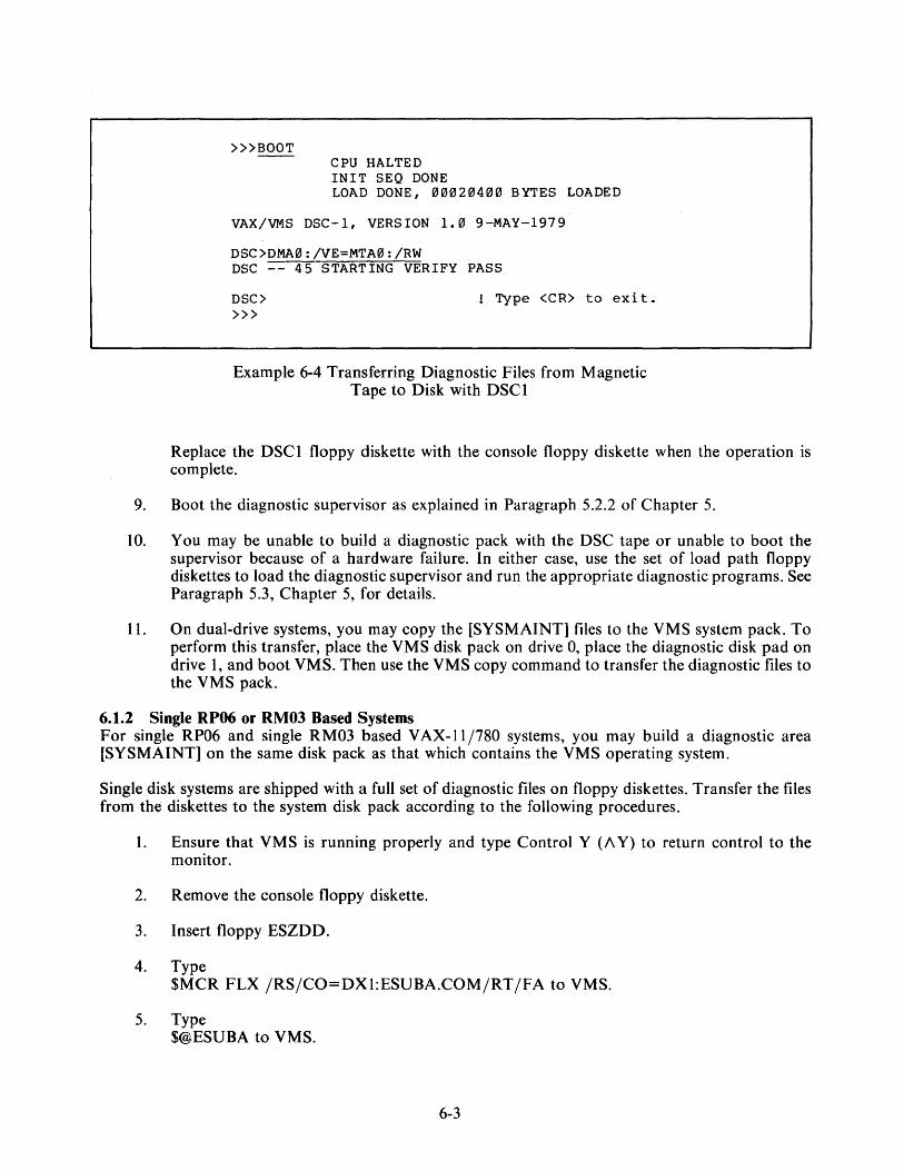
>»BOOT CPU HALTED INIT SEQ. DONE LOAD DONE, 00020400 BYTES LOADED
VAX/VMS DSC-1, VERSION 1.0 9-MAY-1979
DSC>DMA0:/VE=MTA0:/RW DSC -- 45 STARTING VERIFY PASS
DSC> >»
! Type <CR> to exit.
Example 6-4 Transferring Diagnostic Files from Magnetic Tape to Disk with DSCl
Replace the DSCl floppy diskette with the console floppy diskette when the operation is complete.
9. Boot the diagnostic supervisor as explained in Paragraph 5.2.2 of Chapter 5.
I 0. You may be unable to build a diagnostic pack with the DSC tape or unable to boot the supervisor because of a hardware failure. In either case, use the set of load path floppy diskettes to load the diagnostic supervisor and run the appropriate diagnostic programs. See Paragraph 5.3, Chapter 5, for details.
11. On dual-drive systems, you may copy the [SYSMAINT] files to the VMS system pack. To perform this transfer, place the VMS disk pack on drive 0, place the diagnostic disk pad on drive 1, and boot VMS. Then use the VMS copy command to transfer the diagnostic files to the VMS pack.
6.1.2 Single RP06 or RM03 Based Systems For single RP06 and single RM03 based V AX-11 /780 systems, you may build a diagnostic area [SYSMAINT] on the same disk pack as that which contains the VMS operating system.
Single disk systems are shipped with a full set of diagnostic files on floppy diskettes. Transfer the files from the diskettes to the system disk pack according to the following procedures.
1. Ensure that VMS is running properly and type Control Y (A Y) to return control to the monitor.
2. Remove the console floppy diskette.
3. Insert floppy ESZDD.
4. Type $MCR FLX /RS/CO=DXl:ESUBA.COM/RT/FA to VMS.
5. Type $@ESUBA to VMS.
6-3
6. Locate the first floppy diskette containing files to be transferred.
7. Insert the diskette. In response to the prompt message, TYPE IN THE NAME OF THE MOUNTED FLOPPY [<CR>=EXIT], type in the name of the floppy diskette, e.g., ESZAF. After you have transferred the files from all the floppy diskettes, type a carriage return following the prompt message to exit from the ESUBA script. At this point the SYSMAINT area on your system disk is complete.
8. Reinsert the console floppy diskette.
6.2 UPDATING DIAGNOSTIC FILES When you receive a set of floppy diskettes to update the diagnostic files, transfer the new files from the floppy diskettes to the diagnostic system disk pack according to the following procedures.
1. Ensure that VMS is running properly and type a Control Y (/\ Y) on a terminal to return control to the monitor.
2. Locate floppy diskette ZZ-ESZDD and insert it in the floppy disk drive.
3. Type $MCR FLX /RS/CO=DXI:ESUBB.COM/RT /FA to VMS.
4. Type $@ESUBB to VMS.
5. Locate the floppy disk containing the files to be transferred. Insert the diskette; in response to the prompt messsage, TYPE THE NAME OF MOUNTED FLOPPY [<CR>=EXIT], type in the name of the floppy diskette, e.g., ESZAE. The ESU BB script will delete files to be replaced, transfer all of the diagnostic files on the diskette, and then prompt the operator for another floppy diskette. After you have transferred the files from all the update floppy diskettes, type a carriage return following the prompt message to exit from the ESUBB script. At this point your diagnostic system disk is complete.
6. Reinsert the console floppy diskette.
6-4
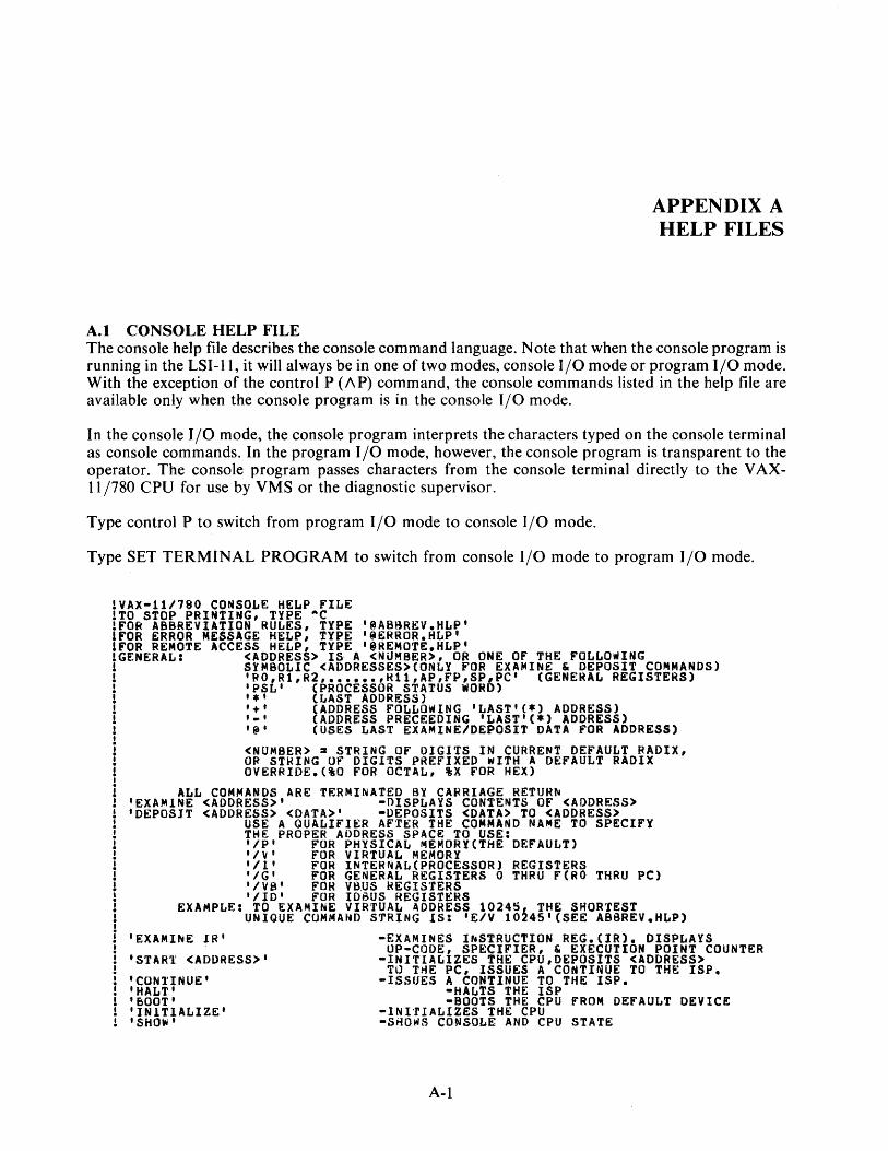
APPENDIX A HELP FILES
A.1 CONSOLE HELP FILE The console help file describes the console command language. Note that when the console program is running in the LSI-11, it will always be in one of two modes, console 1/0 mode or program 1/0 mode. With the exception of the control P (AP) command, the console commands listed in the help file are available only when the console program is in the console 1/0 mode.
In the console 1/0 mode, the console program interprets the characters typed on the console terminal as console commands. In the program 1/0 mode, however, the console program is transparent to the operator. The console program passes characters from the console terminal directly to the VAX-11 /780 CPU for use by VMS or the diagnostic supervisor.
Type control P to switch from program 1/0 mode to console 1/0 mode.
Type SET TERMINAL PROGRAM to switch from console 1/0 mode to program 1/0 mode.
!VAX-111780 CONSOLE HELP FILE !TO STOP PRINTING, TYPE •c !FOR ABBREVIATION RULES, TYPE '@ABBREV.HLP' IFOR ERROR MESSAGE HELP, TYPE '~ERROR.HLP' IFOR REMOTE ACCESS HELP TYPE 1 iREMOT€.HLP' !GENERAL: <ADORES!> I& A <NUMBER>, OR ONE OF THE FOLLOWING ! SYMBOLIC <ADDRESSES>CONLY FOR EXA~INE & DEPOSIT COMMANDS) ! 1 RO,R1,R2, •••••• ,H11,AP,FP,SP,PC 1 (GENERAL REGISTERS) 1 'PSL' (PROCESSOR STATUS WORD) ! '*' (LAST ADDRESS) 1 '+' (ADDRESS FOLLOwING 1 LAST'C*l ADDRESS) ! '·' (ADDRESS PRECEEDING 'LAST'(*) ADDRESS) ! '@' (USES LAST EXAMINE/DEPOSIT DATA FOR ADDRESS) I
i i i I
I I
!
<NUMBER> = STRING OF OIGITS IN CURRENT DEFAULT RADIX, OR STHING OF DIGITS PREFIXED WITH A DEFAULT RADIX OVERRIDE.(%0 FOR OCTAL, %X FOR HEX)
ALL COMMANDS ARE TERMINATED BY CAFRIAGE RETURN 'EXAMINE <ADDRESS>' -DISPLAYS CONTENTS OF <ADDRESS> 'DEPOSIT <ADDRESS> <DATA>' •DEPOSITS <DATA> TO <ADDRESS>
USE A QUALIFIER AFTER THE COMMAND NAME TO SPECIFY THE PROPER ADDRESS SPACE TO USE: 'IP' FOR PHYSICAL MEMORYCTHE DEFAULT) 'IV' FOR VIRTUAL ME~ORY 1 /1 1 FOR INTERNALCPROCESSOR) REGISTERS i1G 1 FOR GENERAL REGISTERS 0 THRU F(RO THRU PC) 1 /VS 1 FOR VB.US REGIS'fERS 1 /ID' FOR IDBUS REGISTERS
EXAMPLE: TO EXAMINE VIRTUAL ADDRESS 102451 THE SHORTEST UNIQUE COM~AHD STRING lS: 'E/V 10i45 1 (SEE ABSREV.HLP)
'EXAMI~E JR'
•START <ADDRESS>'
I CONl'INUE I
'HALT' 'BOOT' 'INITIALIZE' 'SHOW'
•EXAMINES INSTRUCTION REG.CIR). DISPLAYS UP-CODE, SPECIFIER, & EXECUTION POINT COUNTER
•INITIALIZES THE CPU,DEPOSITS <ADDRESS> TO TrlE PC, ISSUES A CONTINUE TO THE ISP.
-ISSUES A CONTINUE TO THE ISP. •HALTS THE ISP •BOOTS THE CPU FROM DEFAULT DEVICE
-INITIALIZES THg CPU -SHOWS CONSOLE AND CPU STATE
A-1

I
'SHOW VERSION' 'TEST' 'TEST/COM' 'UNJAM' 'SET STEP BUS' 'SET STEP STATE' 'SET STEP INSTRUCTION' 1 CLEAR S'l'EP' 'hEXT <NUMBER>'
'QCLEAR <ADDRESS>'
'SET S0'4M' 'CLEAR SOMr.1'
NOTE~ ID REGISTER 21 IS 'SET CLOCK SLOW' 'SET CLOCK FAST' 'SET CLOCK NORMAL' 'SET RELOCATION:<NUMBER>'
-SHifW·s· VERSIONS OF MICROCODE AND CONSOLE •RUNS MICRO•OIAGNOSTICS -LOADS MlCRO•DIAGNOSTICS,AWAITS COMMANDS •UNJAMS THE SBI -ENABLE SINGLE BUS CYCLE CLOCK MODE •ENABLE SINGLE TIME STATE CLOCK MOOE •ENABLES SINGLE INSTRUCTION MODE •ENABLE NORMAL(NO STEP) MODE •<NUMSER> STEP CYCLES ARE DONE, TYPE OF
STEP DEP~NDS ON LAST 'SET STEP' COMMAND •DOES A QUAD CLEAR TO <ADDR€SS>,WHICH IS FORCED
TO A QUAD WORD BOUNDARYCCLEARS ECC ERRORS) •SET 'STOP ON MICRO•MATCH' ENABLE •CLEAR 'STOP ON MlCRO•MATCH' ENABLE THg MICRO•MATCH REGISTER. •SET CPU CLOCK FREQ TO SLOW. •SET CPU CLOCK FREQ TO FAST •SET CPU CLOCK FREQ TO NORMAL •PUT <NUMBER> INTO CONSOLE'S RELOCATION
REGISTER. RELOCATION REGISTER IS ADDED TO EFFECTIVE ADDRESS OF PHYSICAL AHO VIRTUAL EXAMINES AND DEPOSITS.
'SET DEFAULT <OPTION>, ••• ,<OPTION>' •SET CONSOLE DEFAULTS NOTE: <OPTIONS> ARE: OCTAL,HEX,PHYSICAL,VIRTUAL,INTERNAL
GENERAL,VBUS,IOBUS,BYTErWORD,LONGfQUAD 'SET TEHMINAL FILL:<NU~BER>' •SET FILL COUNT FOR t OF BLANKS WR TTEN
'SET TERMINAL PROGRAM' I "PI CCOHTROL•P)
TO THE TER~INAL AFTER <CR> OR <LF> •PUT CONSOLE TTY INTO 'PROGRAM l/0' MODE •PUT CONSOLE TTY INTO 'CONSOLE l/0' MODE
(UNLESS MODE SWITCH IN 'DISABLE') 'HELP' •PRINTS THIS FILE 'f<FILENAME>' •PROCESS AN INDIRECT COMMAND FILE 'LOAD <FILENAME>' •LOAD FILE TO MAIK MEMORY. 'LOAO/WCS <FILENAME>' •LOAD FILE SPECIFIED TO WCS
NOTE: THE 'ISTART:<ADDRESS>' QUALIFIER MAY ALSO BE USED TO SPECIFY THE STARTING ADDRESS FOR A LOAD, OTHERWISE LOAD
i 'LINK' !
WILL BEGIN WITH LOCATION O. •CAUSES CONSOLE TO BEGIN COMMAND LINKING. CONSOLE PRI~TS REVERSED PROMPT TO INDICATE LINKING. ALL COMMANDS TYPED BY USER ~HILE LINKING ARE STORED IN AN INDIRECT COMMAND FI~E FOR LATER EXECUTION. CONTROL•C TERMINATES LINKING.CSEE PERFORM)
' . ' i i I
i 'PERFORM' •EXECUTE A FILE OF LINKED COMMANDS PREVIOUSLY
GENERATED VIA A 'LINK' COMMAND. 'REPEAT <ANY•CONSOLE•COMMAND>' • CAUSES THE CONSOLE TO REPEATEDLY EXECUTE
'WCS'
'ENABLE ox1:• 'REBOOT' 'WAIT DONE'
THE <CONSOLE•COMMAND>, UNTIL STOPPED SY A -c -CALLS MICRO-DEBUGGER. (FOR DEBUGGER HELP,
TYPE '@WCS~ON.HLP 1 ) •ENABLES CONSOLE SOFTWARE TO ACCESS FLOPPY DRIVE
1 ON THOSE SYSTEMS WITH DUAL FLOPPIES. •CAUSES A CONSOLE SOFTWARE RELOAD •WHEN EXECUTED FROM AN INDIRECT COMMAND FILE, THI
COMMAND WILL CAUSE COMMAND FILE EXECUTION TO STO UNTIL: A) A 'DONE' SIGNAL IS RECEIVED FROM THE PROGRAM RUNNING IN THE VAX•11/780CCOMMAND FILE EXECUTION wILL CONTINUE), OR 8) THE VAX•ll/780 HALTS, OR OP€RATOR TYPES A -cccoMMAND FILE EX• ECUTION WILL TERMINATE).
A.2 CONSOLE ABBREVIATION RULES
VAX•11/780 CONSOLE ABBREVIATION RULES THIS FILE SHOWS THE SHORTEST UNIQUE co~~AND STRINGS THAT WILL BE RECOGNIZED AS THE CONSOLE COMMAND LISTED.
COMMAND 'EXAMINE <ADDRESS>' 'DEPOSIT·<ADDRESS> <DATA>' 'START <ADDRESS>' 'CONTINUE' 'HALT' 'HELP' 'BOOT' 'INITIALIZE' 'SHOW' 'SHOW VERSION' 'TEST' 'UNJAM' 'SET RELOCATIO~:<NUMBER>' 'SET STEP BUS' 'SET STEP s·u TE' 'SET STEP lNST~UCTION'
SHORTEST ABBREVIATION RECOGNIZED 'E <ADDRESS>' 'D <ADDRESS> <DATA>' 'S <ADDRESS>' 'C' 'H' 'HE' 'i~' I I' 'SH' 'SH V' 'T' 'u' 'SF.: R:<NUMBER>' 'SE S 8' 'SE S S' 'SES I'
A-2

1 1 CLEAR STEP' 'CL S" 1 'NEXT <NUMBER>'
'QCLEAR <ADDRESS>' 'SET SOMM 1
'N <NUMBER>' 1 Q <ADDRESS>' 'SE SO'
'CLEAR SOMM' 'SET CLOCK FAST' 'St:T CLOCK SLOW' 'SET CLOCK NORMAL' '!'<FILENAME>' 'LOAD <FILENAME>' 1 LINl< 1
1 PERft"ORM 1 1 kEPEAT <CONSOLE•COMMAND>'
'CL so• 'St-: C F 1
'SE C S' 'SE C N' '~<FILENAME>' 'L <FILENAME>' 'LI' 'P' 'R <CONSOLE•COMMANO>'
• I WCS I ' " ' 'ENABLE DXl:' 'REBOOT'
'EN DXl:' 'REB'
1 SET TERMINAL FlLL:<NUMB~R>' 'SET TERMINAL PROGRAM'
•sg T F:<NUMBER>' 'St: T PR'
'SET DEFAULT <OPTION-LIST>' 'WAIT DONE'
'SE D <OPTION•LIST>' I WA I) I
QUALIFIERS /HUE /flORD /LONG /QUAD /OCTAL /HEX /PHYSICAL /VIRTUAL /INTERNAL /Gl!:NERAL /VBUS /IDBUS /WCS /NEXT:<NUMBER> /COMMAND /START:<ADDRESS> <END•OF•ABBREV.HLP>
SHORTEST ABBREVIATION RECOGNIZED IB IW IL IQ 10 IH IP IV II IG /VB IID /WC /N:<NUMBER> IC IS:<ADDRESS>
A.3 ERROR MESSAGE HELP FILE
!VAX-111780 ERROR MESSAGE HELP FILE ' i i 1 1 1 1
?'<TEXT•STRING>' IS INCOMPLETE THE <TEXT•STRING> IS NOT A COMPLETE CONSOLE COMMAND
?'<TEXT•STRIHG> 1 IS INCORRECT THE <TEXT•STRING> IS HOT RECOGNIZED AS PART OF A COMMAND
?FILE NAME ERR
1 ?FILE 1
A <FILE•NAME> GIVEN WITH A COMMAND CAN NOT BE TRANSLATED TO RAOSO NOT FOUND A <FILE•NAME> GIVEN WITH A 'LOAO' OR '~' COMMAND DOES NOT ~ATCH ANY FILE ON THE CURRENTLY LOADED FLOPPY DISC. CAN ALSO !
1 • i ?NO i
BE GENERATED 8Y 'HELP 1 ,'80QTt, OR AN ATTEMPTED WCS LOAD IF HELP FILE, BOOT FILE, OR WCS FILE IS MISSING FROM FLOPPY.
CPU RESPONSE CONSOLE TIMEO•OUT WAITING FOR A RESPONSE FRO~ CPU
NOT IN CONSOLE WAIT LOOP, COM~AND ABORTED i ?CPU 1 A CONSOLE COMMAND REQUIRING ASSISTANCE FROM CPU WAS ISSUED
WHILE THE CPU WAS NOT IN THE CONSOLE SERVICE LOOP 1 l ?CPU CLK STOP, COMMAND ABORTED A CONSOLE CO~MAND THAT REQUIRES THE CPU CLOCK TO BE RUNNING WAS ISSUED WHILE THE CLOCK WAS STOPPED i
i i ' i i i
?FLOPPY ERR,COOF.:X THE CONSOL~ FLOPPY DRIVER DETECTED AN ERROR. CODES ARE AS FOLLOWS:(CODES ARE ALWAYS PRlNTEO IN HEX RADIX) CODE=1 FLOPPY HARDWARE ER~ORCCRC,PARITY,ETC) CODE=2 FILE NOT FOUND COOE=3 FLOPPY DRIVER QU~UE OVERFLO~ CODE=4 CONSOLE SOFTWARE REQUESTED AN ILLEGAL SECTOR NUMBER
?FLOPPY NOT READY THE CONSOLE FLOPPY l>RIVE FAILED TO BECOME READY WHEN BOOTING.
?NO BOOT ON FLOPPY CONSOLE ATT~~PTeO TO BOOT FROM A FLOPPY THAT DOES NOT CONTAIN A VALlO BOOT BLOCK.
?FLOPPY ERROR ON BOOT A FLOPPY ERROR ~AS DETECTED WHILE ATTEMPTING A CONSOLE BOOT.
?MIC•ERR ON FUNCTION A MlCRO•ERROR OCCURRED IN THE CPU WHILE SERVICING A CONSOLE REQUEST. SBI ERROR REGISTERS ARg DU~PEO AFTER THIS MESSAGE IS PRINTED.
?INT•REG ERR A MlCRO-ERROR OCCURRED WriILE ATTEMPTING TO REFERENCE A CPU INTERNALCPROCESSOR) REGISTER. AN ILLEGAL ADDRF.SS WILL CAUSE THIS ERROR.
A-3

?~ICR-0-ERR, tODE=X AN UNRECOGNIZED MICRO•ERROR OCCURRED. TH€ CODE RETURNED BY THE CPU IS NOT IN THE RANGE OF RECOGNIZED ERROR CODES. 'X' lS THE CODE THAT WAS RETURNED SY THE CPU.
?INT•STK INVLD THE CPU HALTED BECAUSE THE INTE~RUPT STACK WAS MARKED INVALID
?CPU OSLE-ERR HLT THE CPU HAS DONE A 'DOUBLE ERROR' HALT
?ILL l/E VEC THE CPU DETECTED AN ILLEGAL INTERRUPT/EXCEPTION VECTOR
?NO USR wCS CPU DETECTED AN INTERRUPT/EXCEPTION VECTOR TO USER WCS ANO NO USER WCS EXISTS
?CHM ~RR A CHANGE MODE INSTRUCTION wAS ATTEMPTED FROM THE INTERRUPT STACK
?MEM·~:Nvi~¥bilc~~~:~~E OR DEPOSIT CAUSED AN ERROR IN THE MEMORY MANAGEMENT MICRO•ROUTINE. 'XX' IS A ONE BYTE ERROR CODE RETURNED Bt THE ROUTINE, WITH THE FOLLO~ING SIT ASSIGNMENTS: BIT 0 = LENGTH VIOLATIONCBITS NUMBERED FRO~ RIGHT) BIT 1 = FAULT wAS ON A PTE REFERENCE BIT 2 = WRITE OR MODIFY INTE~T BIT 3 = ACCESS VIOLATION BITS 4 THRU 1 SHOULD BE IGNORED
?lND•COM ERR THE CONSOLE DETECTED AN ERROR IN THE FORMAT OF AN INDIRECT COMMAND FILE. POSSIBLE ERRORS ARE: 1) MORE THAN 80 CHARACTERS IN AN INDIRECT COMMAND LINE, 2) A COMMAND LINE DID NOT END WITH A CARRIGE RETURN ANO .LINE FEED.
UT PENDING THIS IS NOT ACTUALLY AN ERROR, BUT INDICATES THAT AN ERROR WAS PENDING AT THE TIME THAT A CONSOLE•REQUESTEO HALT WAS PERFORMED. CONTINUE CPU TO CLEAR INTERRUPT.
?WARNING•wCS & FPLA VER MISMATCH THE MICROCODE IN WCS IS NOT COMPATIBLE WITH FPLA. THIS MESSAGE IS PRINTED ON EACH ISP START OR CONTINUE,BUT NO OTHER ACTION TAKEN BY CONSOLE.
?FATAL•WCS & PCS VER MISMATCH THE MICROCODE IN PCS IS NOT COMPATIBLE WITH THAT IN WCS. ISP START ANO CONTINUE A~E DISABLED BY CONSOLE.
?MICRO•MACHINE TIME OUT INDICATES THAT THE VAX•ll/780 MICRO•MACHINE HAS FAILED TO STROBE INTERRUPTS WITHIN THE MAX TIME PERIOD ALLOWED.
?REMOTE ACCESS NOT SUPPORTED PRINTED WHEN CONSOLE MODE SWITCH ENTERS A 'REMOTE' POSITION AND THE REMOTE SUPPORT SOFTWARE IS NOT INCLUDED IN THE CONS6LE.
?TRAP-4, RESTARTING CONSOLE THE CONSOLE TOOK A TIME•OUT T~AP. CONSOLE WILL RESTART.
?UNEXPECTED TRAP MOUNT CONSOLE FLOPPY, THEN TYPE ~c
CONSOLE TRAPP~D TO AN UNUSED VECTOR. CONSOLE REBOOTS ~HEN AC TYPED ?Q•BLKD'
CONSOLE'S TERMINAL OUTPUT QUEUE IS BLOCKED. CONSOLE wILL REBOOT. ?CANT DISABLE BOTH FLOPPIES, FUNCTION ABORTED
AN ATTEMPT WAS MADE TO DISABLE BOTH THE REMOTE AND LOCAL FLOPPY <ENO•OF•ERROR.HLP>
A.4 REMOTE ACCESS HELP FILE
lVAX•lt/780 CONSOLE • REMOTE ACCESS HELP FILE 1
'ENABLE TALK' •ESTABLISH TERMINAL TO TERMINAL COMMUNICATION BETWEEN LOCAL ANO REMOTE TERMINAL. KEYS STRUCK ON ONE TERMINAL ARE PRINTED ON THE OTHER. CONTROL•P TERMINATES TALK.
'ENABLE ECHO' •CAUSES CHARACTERS TYPED IN TALK MODE TO BE ECHOED BACK TO THE ORIGINATING TERMINAL.
'ENABLE LOCAL COPY' •CAUSES THE LOCAL TERMINAL TO GET A COPY OF OF OUTPUT BEING SENT TO REMOTE TERMINAL.
'ENABLE LOCAL CONTROL'•ALLOWS LOCAL TERMINAL TO CONTROL SYSTEM WHEN CONSOLE SWITCH IS IN REMOTE POSITION(S). DIS• ABLED BY A CONTROL•P FROM THE REMOTE TERMINAL.
'ENABLE CARRIER ERROR'•CAUSE CONSOLE TO PRINT '?CARRIER LOST' WHEN A LOSS OF CARRIER IS DETECTED AT REMOTE INTERFACE.
'DISABLE ECHO' •INHIBITS ECHO OF CHARACTERS TYPED IN TALK MODE. 'DISABLE LOCAL COPY' •DISABLE LOCAL TgR~INAL FRO~ RECEIVING COPY OF
OUTPUT TO RE~OTE TERMINAL. 'DISABLE CARRIER ERROR'•CAUSES CONSOLE TO INHIBIT PRINTING OF CARRIER
LOST MESSAGE wHEN LOSS OF CARRIER DETECTED. 'ENABLE LOCAL FLOPPY' -(AFFECTS PROTOCOL OPERATION ONLl) ON AN ATTEMPT
TO OPEN A FILE, THE DIRECTORY OF LOCAL FLOPPY WILL BE SEARCHED FIRST. IF FILE IS NOT FOUND,
'REMOTE' FLOPPY'S DIRECTORY IS SEARCHED FOR FILE. 'DISABLE LOCAL FLOPPY'•CAFFECTS PROTOCOL OPERATION ONLY) ON AN ATTEMPT
TO OPEN A FILE, THE FILE IS SEARCHED FOR ON TH~ 'RE~OTE' FLOPPY ONLY.
A-4

'DISABLE REMOTE FLOPPY'•ON AN ATTEMPT TO OPEN A FILE, ONLY THE DIRECTORY OF THE LOCAL FLOPPY WILL BE SEARCHED. THIS COM~ANO AND 'DISABLE LOCAL FLOPPY' ARE MUTUALLY EXCLUSIVE.
'ENABLE REMOTE FLOPPY' •ALLOWS THE DIRECTORY OF THE 'REMOTE' FLOPPY TO 8E SEARCHED ON AN ATTEMPT TO OPEN A FILE.
ENO-OF•REMOTE.HLP
A.5 MICRO-DEBUGGER HELP FILE
1MICRO•OEBUGGER HELP FILE 'TO STOP PRINTING, TYPE AC
DEBUGGER COMMANOS(ALL TERMINATED BY CARRIAGE RETURN)
'E/P <ADDRESS>' -EXAMINE PHYSICAL MEMORY 'EIIO <ADDRESS>' -EXAMINE ID BUS REGISTER
:i ~~gg~~~~~·<FIELDNAME•1>f<FIE~~~~~~~2~~~,~~~~lfg~AM~!~~LAY ALL FIELDS EXAM NE WCS LOCATION, DISPLAY ONLY FIELDS THE FIELDS SPECIFIED.
NOTE: <FIELONAMES> = ACF,ACM,ADS,ALUfBEN,BMX,CCK,CID,DK,OT,EAL ESM,FEK,FS,IBC, EK,UJM,KMX,MCT,MSC,PCK,QK RMX,SCK,SGN,SHF,Sl,SMX,SPO,USU,VAK
'E RA <ADDRESS>' •EXAMINE AN RA REGISTER 'E RC <ADDRESS>' -EXAMINE AN RC REGISTER 1 E <SYMBOLIC•NAME>' -EXAMINE ONE OF THE SYMBOLICALLY NAMED
REGISTERS NOTE: <SYMBOLIC-NAMES> = DR,FER,IBA,LA,LB,I,c,a,RL,SC,SR,UPC
1 0/P <ADDRESS> <DATA>' 1 0/10 <ADDRESS> <DATA>'
-DEPOSIT <DATA> TO PHYSICAL MEMORY •DEPOSIT <DATA> TO ID BUS ~EGSITER
1 0 <ADDRESS> <FIELDNAME-1> (0ATA•l>,<FIELDNAME•2> <DATA-2>, •••••••• •DEPOSIT TO WCS LOCATION, PUTTING <DATA-1>
INTO <FI~LDNAME·l>, ETC. UNSPECIFIED FIELDS ARr~ UNCHANGED.
NOTE: THE 1 /Z' QUALIFIER MAY BE USED TO CAUSE ALL UNSPECIFIED FIELDS TO BE CLEARED.
1 0 P.A <ADDRESS> <DATA>' 'D RC <ADDRESS> <DATA>'
•DEPOSIT <DATA> TO AN RA REGISTER •DEPOSIT <DATA> TO AN ~C REGISTER
'D <SY~BOLIC-NAME> <DATA>' -DEPOSIT <DATA> TO ONE OF THE SYMBOLICALLY NAMED REGISTERSCSEE LIST ABOVE).
NOTE: DEPOSITS TO THE RLOG ST4CKCRL) ARE NOT SUPPORTED.
'CONTIMUE'
'START <ADDRESS>'
'HALT'
'SET SOMM' 'CLEAR SOMM' 1 SE1' STEP'
'CLEAR STEP'
'RETURN'
•RESUME MICRO•INSTRUCTION EXECUTION AS SPECIFIED BY CONTENTS OF MICRO•PCCUPC)
•START MICRO•SEQUENCF.R AT <ADDRESS>.
•HALT THE MICRO-SEQUENCER
-SET THE rsTOP ON MICRO-MATCH' ENABLE •CLEAR THE 'STOP ON MICRO•MATCH' ENABLE
-~NABLE SINGLE MICRO•INSTRUCTION STEP MODE. START OR CONTINUE WILL ALLOW ONE MICRO• INSTRUCTION TO EXECUTE, THE~ HALT THE MICRO•SEQUENCER.
•DISABLE SINGLE MICRO•INSTRUCTION STEP MODE.
•RETURN TO THE CONSOLE PROGRAM
'OPEN <FILENAME>' -OPEN SPECIFIED FILE ON FLOPPY DRIVE 0 'OPEN DX1:<FILENAME> 1 •OPEN SPECIFIED FILE ON FLOPPY DRIVE 1
NOTE: 'OPEN' IS USED TO SPECIFY A FILE CONTAINING THE MICRO•CODE CURRENTLY LOADED IN THE WCS PORTION OF THE CONTROL STORE. (ADDRESSES 1000(16) & UP IN THE CONTROL STORE) THIS FILE WILL BE USED FOR ALL EXAMINES OF THE WCS, SINCE THE WCS IS NOT DIRECTLY READABLE.
<END•OF•WCSMON.HLP>
A-5
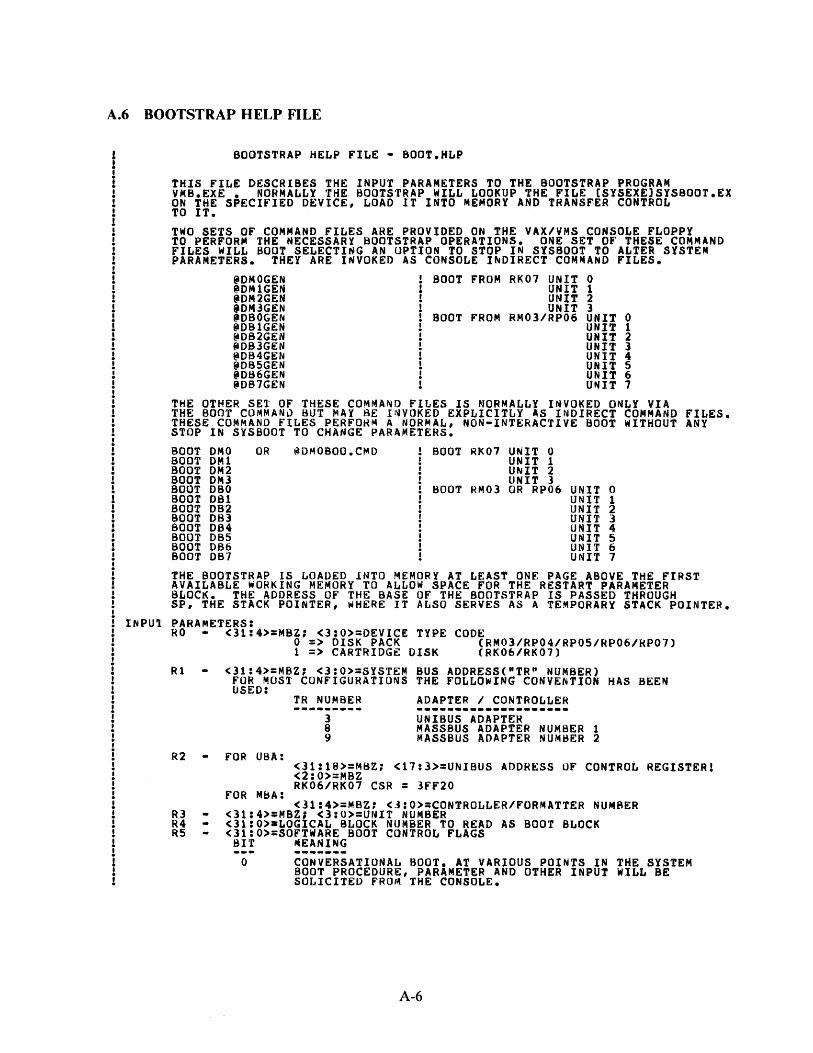
A.6 BOOTSTRAP HELP FILE
BOOTSTRAP HELP FILE • SOOT.HLP
THIS FILE DESCRIBES THE INPUT PARAMETERS TO THE BOOTSTRAP PROGRAM VMS.EXE • NORMALLY THE BOOTSTRAP WILL LOOKUP THE FILE CSYSEXElSYSBOOT.EX ON THE SPECIFIED DEVICE, LOAD IT INTO MEMORY AND TRANSFER CONTROL TO IT.
TWO SETS OF COMMAND FILES ARE PROVIDED ON THE VAX/VMS CONSOLE FLOPPY TO PERFORM THE NECESSARY BOOTSTRAP OPERATIONS. ONE SET OF THESE COMMAND FILES WILL BOOT SELECTING AN OPTION TO STOP IN SYSBOOT TO ALTER SYSTEM PARAMETERS. THEY ARE INVOKED AS CONSOLE INDIRECT COMMAND FILES.
~DMOGEN BOOT FROM RK07 UNIT 0 ~DM1GEN UNIT 1 ~DM2GEN UNIT 2 iDM3GEN UNIT 3 'OBOGEN BOOT FROM RM03/RP06 UNIT 0 ~081GEN UNIT 1 @082GEN UNIT 2 @D83GEN UNIT l ~DB4GEN UNIT 4 @085GEN UNIT 5 @DB6GEN UNIT 6 ~OB7GEN U~IT 7
THE OTHER SEt OF THESE COMMAND FILES IS NORMALLY INVOKED ONLY VIA THE BOOT COMMAND BUT MAY SE I~VOKED EXPLICITLY AS INDIRECT COMMAND FILES. THESE COMMAND FILES PERFOH~ A NORMAL, NON•INTERACTlVE BOOT WITHOUT ANY STOP IN SYSBOOT TO CHANGE PARAMETERS.
BOOT OMO OR tiDMOBOO.Cl\40 BOOT RI<07 UNIT 0 BOOT DM1 UNIT 1 BOOT DM2 UNIT 2 BOOT OMl UNIT 3 BOOT DBO BOOT RM03 OR RP06 UNIT 0 BOOT 081 UNIT 1 BOOT 082 UNIT 2 BOOT 083 UNIT 3 SOOT 084 UNIT 4 BOOT DBS UNIT 5 BOOT 086 UNIT 6 BOOT 087 UNIT 7
THE BOOTSTRAP IS LOADED lNTO MEMORr AT LEAST ONE PAGE ABOVE THE FIRST AVAILABLE WORKING MEMORY TO ALLOW SPACE FOR THE RESTART PARAMETER BLOC~. THE ADDRESS OF THE BASE OF THE BOOTSTRAP IS PASSED THROUGH SP, THE STACK POINTER, WHERE IT ALSO SERVES AS A TEMPORARY STACK POINTER.
INPU1 PARAMETERS: RO • <31:4>:MBZ; <3:0>=DEVICE TYPE CODE
0 => DISK PACK (RM03/RP04/RP05/RP06/HP07) 1 => CARTRIDGE DISK CRK06/RK07)
R1 <31:4>=MBZJ <3:0>=SYSTEM SUS ADDRESSC"TR" NUMBER) FOR MOST CONFIGURATIONS THE FOLLOWING CONVE~TION HAS BEEN USED:
R2 FOR UBA:
FOR MBA:
TR NUMBER
---------] 8 9
ADAPTER I CONTROLLER
UNIBUS ADAPTER ~ASSBUS ADAPTER NUMBER 1 MASSBUS ADAPTER NUMBER 2
<31:18>=MBZ; <17:3>=UNIBUS ADDRESS OF CONTROL REGISTER! <2:0>=MBZ RK06/RK07 CSR = 3FF20
<31:4>=MBZ1 <3:0>:CONTROLLER/FORMATTER NUMBER R3 <31:4>:MBZ; <3:0>=UNIT NUMBER R4 <3l:O>•LOGICAL BLOCK NUMBER TO READ AS BOOT BLOCK RS <31:0>=SOFTWARE BOOT CONTROL FLAGS
SIT ~EANING
0 CONVERSATIONAL BOOT. AT VARIOUS POINTS IN THE SYSTEM BOOT PROCEDURE, PARAMETER AND OTHER INPUT WILL BE SOLICITED FROM THE CONSOLE.
A-6

I
i 1 1 I
i 1 I
i i i i i i i i
1
2
3
8 5
6
1
8
9
DEBUG. THIS FLAG IS PASSF.D THROUGH TO VMS AND CAUSES THE CODE FOR THE EXEC DEBUGGER TO BE INCLUDED IN THE RUNNING SYSTEM.
INITIAL BREAKPOINT. IF THIS FLAG IS SET, AND THE EXEC DEBUGGER CODE IS INCLUDED CfLAG BIT 1) THEN A BREAKPOINT WILL OCCUR !~MEDIATELY AFTER THE EXEC ENABLES MAPPING.
BOOT BLOCK. lF THIS FLAG IS SET THEN THE BOOT BLOCK WILL BE READ ANO CONTROL TRANSFERED TO IT.
DIAGNOSTIC BOOT. THIS FLAG CAUSES A BOOT BY FILE NAME FOR THE DIAGNOSTIC SUPERVISOR.
BOOTSTRAP BREAKPOINT. THIS FLAG CAUSES THE BOOTSTRAP TO STOP A BREAKPOINT AFTER PERFORMING NEcgssARY INITIALIZATION IF lT HAS sgEN BUILT wITH DEBUG CODE.
IMAGE HEADER. IF THIS FLAG IS SET THE TRANSFER ADDRESS FROM THE IMAGE HEADER OF THE BOOT FILE wILL BE USED. OTHERWISE CONTROL ~ILL TRANSFER TO THE FIRST BYT OF THE BOOT FILE.
MEMORY TEST INHIBIT. THIS FLAG INHIBITS THE TESTING OF MEMORY DURING BOOTSTRAPPING.
FILE NAME. CAUSES THE BOOTSTRAP TO SOLICIT THE NAME OF THE BOOT FILE.
HALT BEFORE TRANSFER. CAUSES A HALT INSTRUCTION TO BE EXECUTED PRIOR TO THE TRANSFER TO THE BOOTFILE. THIS OPTION lS USF.FUL FOR DEBUGGING PURPOSES.
SP ADDRESS+c~x200> OF flHST WORKING 64KB MEMORY REGION USABLE AS BOTH STACK POINTER ANO POINTER TO GOOD MEMORY.
OUTPUT PAR~METERS: RlO • R11 SP PRS-SCBB -
SASE ADDRESS OF REGION CONTAINING SECONDARY BOOTSTRAP POINTER TO RESTART PARAMETER BLOCK (RPS) STACK POINTER SYSTEM CONTROL BLOCK BASE REGISTER
MEMORY LAYOUT AT START OF SECONDARY BOOTSTRAP:
+•••••••··-·-·-------·-·••••••••••••••••••+ :BASE I I
i RESTART PARAMETER BLOCK CRPB) i i i +•••••••••••••••••••••••••••••••••••••••••+ :BASE+•X200 ' ' i PRIMARY BOOTSTRAP CODE i ' ' i i +•-••••••••••••-•••••··-·-··•••••••·-··-··+ :PRS-SCBB I I
i SYSTEM CONTROL BLOCK i ! I +•••••••••••••••••••••••••••••••••••••••••+ :PFNMAP I I
i PFN BITMAP i I ! +•••••••··---------------~---·••••••••••••+ ZPFNMAP+AX800 I I
i BOOTSTRAP STACK i I I +••••••••••••••••••••••••••·-·······------+ :CSP) ' ' i SECONDARY BOOTSTRAP CODE i i i +----------------------------------------·+
J\.-7

APPENDIX B MICRODIAGNOSTIC MONITOR COMMANDS
The majority of the commands availa_ble in the microdiagnostic monitor are not used in the normal course of execution. Normally, the operator enters the TEST command and executes the entire microdiagnostic package. The command mode is usually used following error detection. Following the error message printout, testing stops, and control is returned to the monitor command mode. At this point, the operator executes those microdiagnostic commands which would be most helpful.
Symbols used in the command descriptions are the comma and angle brackets. The comma is used to separate items within a list. Angle brackets denote an argument; that is, either an address, pass count value, or a V bus channel. Note that every command (or command line) must be terminated with a carriage return (CR).
Control C (AC) is the user interrupt control character. If /\C is entered during test execution, the current test will be completed, further testing is terminated, and control is returned to the monitor command mode. If AC is entered while a test is looping on an error, the loop will be suspended and control returned to the monitor command mode. Any command may be aborted if a AC is entered in that command line.
The following list describes the monitor commands. Note that although all commands, keywords, qualifiers, and flags are spelled out, they can be abbreviated to the first two characters. The only exceptions are the HALTD and HAL TI flags, which must be typed HD and HI, respectively.
Diagnose Commands
DIAGNOSE or DIAG Initializes the program control flags, and starts microdiagnostic execution at test number one.
Valid qualifiers are: /TEST: <NUMBER> - Dispatch to the test number specified (do not execute any prior tests) and loop on the test indefinitely.
/SECTION: <NUMBER> - Dispatch to the section number specified (do not execute any prior sections) and loop on the section indefinitely.
/PASS: <NUMBER> - Execute the microdiagnostics the specified number of passes before returning to the console. If the number is -1, execute the microdiagnostics.
/CONTINUE - This switch is used with the /TEST or /SECT switch to automatically continue after the specified test of section has been reached.
B-1

Diagnose Commands (Cont)
DIAGNOSE or DIAG
/TEST: <N> <M> - Dispatch to test <N>, execute tests <N>through <M> (inclusive), and return to command mode.
/SECT: <N> <M> - Dispatch to section <N>, execute sections <N> through <M> (inclusive), and return to command mode.
NOTES In the above variations of the /TEST and /SECTION qualifiers, the value of <N> must be less than or equal to <M>. If <M> is less than <N>, testing will start at <N> and continue to the end.
/TEST and /SECT cannot be specified simultaneously.
Examples: DIAG/TEST:2F
DIAG/SECT:B
DIAG/PASS:-1
DIAG/TEST:2F /CONT
Continue Commands
CONTINUE or CONT
Set and Clear Commands
SET /CLEAR FLAG HD
SET /CLEAR FLAG HI
SET/CLEAR FLAG LOOP
SET /CLEAR FLAG NER
SET /CLEAR FLAG BELL
SET /CLEAR FLAG ERABT
Dispatch to test number 2F and execute it indefinitely.
Dispatch to section number B and execute it indefinitely.
Execute all of the microdiagnostics indefinitely.
Dispatch to test 2F and start execution of the remaining tests.
Continues microdiagnostic execution without changing the program control flags.
Sets (or clears) the halt on error detection flag.
Sets (or clears) the halt on error isolation flag.
Sets (or clears) the loop on error flag.
Sets (or clears) the no error report flag.
Sets (or clears) the bell on error flag.
Sets (or clears) the error abort flag.
B-2
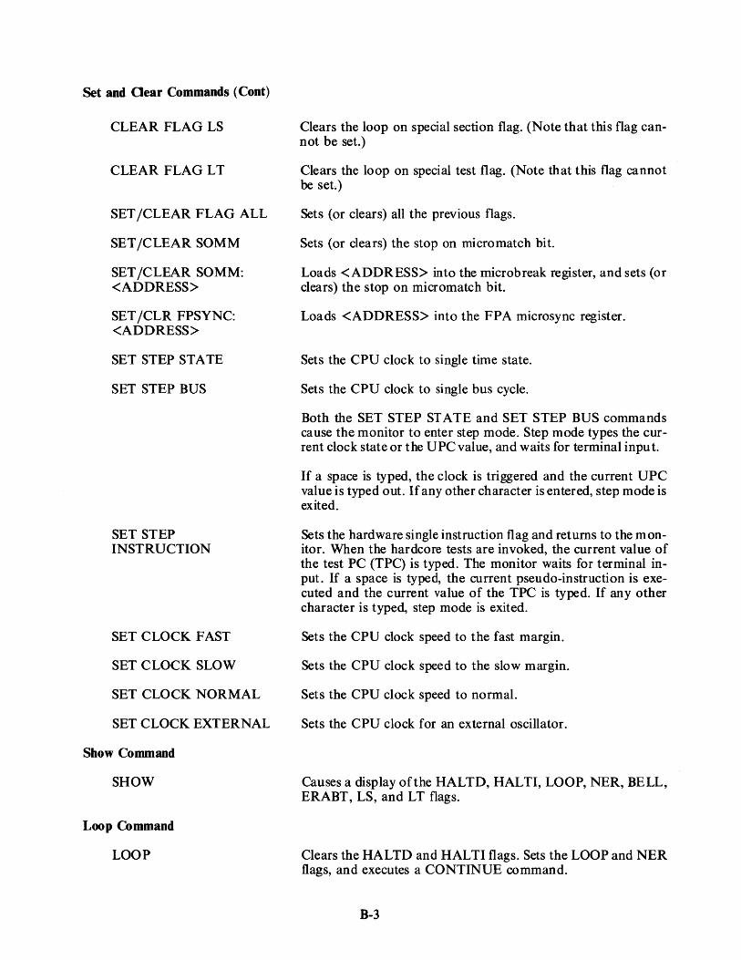
Set and Oear Commands (Cont)
CLEAR FLAG LS
CLEAR FLAG LT
SET /CLEAR FLAG ALL
SET /CLEAR SOMM
SET /CLEAR SOMM: <ADDRESS>
SET /CLR FPSYNC: <ADDRESS>
SET STEP STATE
SET STEP BUS
SET STEP INSTRUCTION
SET CLOCK FAST
SET CLOCK SLOW
SET CLOCK NORMAL
SET CLOCK EXTERNAL
Show Command
SHOW
Loop Command
LOOP
Clears the loop on special section flag. (Note that this flag cannot be set.)
Clears the loop on special test flag. (Note that this flag cannot be set.)
Sets (or clears) all the previous flags.
Sets (or clears) the stop on micromatch bit.
Loads <ADDRESS> into the microbreak register, and sets (or clears) the stop on micromatch bit.
Loads <ADDRESS> into the FPA microsync register.
Sets the CPU clock to single time state.
Sets the CPU clock to single bus cycle.
Both the SET STEP ST ATE and SET STEP BUS commands ca use the monitor to enter step mode. Step mode types the current clock state or the UPC value, and waits for terminal input.
If a space is typed, the clock is triggered and the current UPC value is typed out. If any other character is entered, step mode is exited.
Sets the hardware single instruction flag and returns to the monitor. When the hardcore tests are invoked, the current value of the test PC (TPC) is typed. The monitor waits for terminal input. If a space is typed, the current pseudo-instruction is executed and the current value of the TPC is typed. If any other character is typed, step mode is exited.
Sets the CPU clock speed to the fast margin.
Sets the CPU clock speed to the slow margin.
Sets the CPU clock speed to normal.
Sets the CPU clock for an external oscillator.
Causes a display of the HALTD, HALTI, LOOP, NER, BELL, ERABT, LS, and LT flags.
Clears the HALTD and HAL TI flags. Sets the LOOP and NER flags, and executes a CONTINUE command.
B-3

Return Command
RETURN
Examine Commands
EXAMINE ID:<ADDRESS>
EXAMINE VBUS:<CHANNEL>
EXAMINE RA:<ADDRESS>
EXAMINE RC:<ADDRESS>
EXAMINE LA
EXAMINE LC
EXAMINE DR
EXAMINE QR
EXAMINE SC
EXAMINE FE
EXAMINE VA
EXAMINE PC
Deposit Commands
Returns control to the console program.
The following examine commands cause the current microinstruction to be executed before the examine is performed, if it is the first examine since entering the monitor command mode. Successive examines do not execute . any additional microinstructions. ID bus register contents Tl-T8 are destroyed during the examines,- except for the ID bus and V bus examines. All of the following examines, except V bus, advance the clock to CPTO before executing the command.
Displays the contents of the ID bus register specified by <ADDRESS>.
Displays the contents of the V bus channel specified by <CHANNEL>. Bit 0 is at the right side of the display.
Displays the contents of the RA scratchpad specified by <ADDRESS>.
Displays the contents of the RC scratchpad specified by <ADDRESS>.
Displays the contents of the LA latch.
Displays the contents of the LC latch.
Displays the contents of the D register.
Displays the contents of the Q register.
Displays the contents of the SC register.
Displays the contents of the FE register.
Displays the contents of the VA register.
Displays the contents of the program counter register.
The deposit command is the same as the examine command, except that the data to be deposited must be supplied by the user.
DEPOSIT ID:<ADDRESS> <DATA> DEPOSIT RA:<ADDRESS> +DATA> DEPOSIT RC:<ADDRESS> <DATA> DEPOSIT LA:<DATA> DEPOSIT LC:<DATA> DEPOSIT DR:<DATA> DEPOSIT QR:<DATA> DEPOSIT SC:<DATA> DEPOSIT FE:<DATA> DEPOSIT VA:<DATA> DEPOSIT PA:<DATA>
B-4

APPENDIX C CONSOLE BOOT /TROUBLESHOOTING FLOW
If the console program does not start and run properly when the V AX-11 /780 system is powered up, and a problem in the console subsystem is suspected, proceed as follows.
Action
Turn de off Turn ac off Push HALT /ENABLE switch down (halt)
Turn ac on
Turn de on
Response
DC ON (LED on LSI-I I control pan(!l) 173000 @ (printed on terminal) RUN (light flashes)
If the responses are incorrect, go to Figure C-1, Console DC ON Flowchart.
Examine location 173000 type 113000 I
Examine location 037776 type 037776/
173000/000137
037776 /XXXXXX
If the response is not correct, go to Figure C-2, Examine 173000 Flowchart.
Push HALT /ENABLE switch up (ENABLE)
Ensure that diskette ZZ-ESZAB is installed properly in the floppy disk drive.
Type 1402000 BOOT
This command executes the ROM resident quick check console subsystem diagnostics. Upon successful completion of these tests, the ROM code boots the console program from the floppy disk. If the boot fails, go to the 1402000 Console Boot Failure Flowchart (Figure C-3). The program listing for the ROM resident diagnostics (ESKAA.DOC) should be referenced when using this flowchart.
C-1

DC ON, RUN LIGHT FLASH, AND/OR 173000 PRINTOUT DID NOT OCCUR
xxxxxx @ WAS PRINTED CPU JUMPER IS WRONG OR CPU IS BAD
rBDMR L
NO. GO TO POWER FLOW PRINTOUT GARBLED. CHECK BDALO BREF L BSACK L ASSERTED AND GO TO TERMINAL FLOW
ONE OF THE FOLLOWING BDOUT L
SIGNALS IS ASSERTED BRPLY L IS DC ON LED ON? YES. WHAT WAS BOIN L
PRINTED? BSYNC L NOTHING BPOK HIS NOT ASSERTED BDMG 0 L YES. DID THE WAS PRINTED
RUN LIGHT FLASH? BOAL 1 L '-
GO TO TERMINAL FLOW NO. CHECK POWER SUPPLY TO
NO. REMOVE M9400-YE. DOES BACKPLANE CABLE
TERMINAL PRINT 173000 ON flOWER UP? NO. CHECK BDCOK H NOT NO. IS THE ASSERTED RUN LIGHT ON?
NO. CPU IS BAD
YES. CABLING IS INCORRECT
YES. THE HALT SWITCH !S YES. CIB IS BAD
NOT ASSERTING SHALT L
YES. WAS YES. CPU IS BAD YES. CABLING OR CIB IS BAD
PROMPT PRINTED? NO. CHECK JUMPER
NO. REMOVE M9400-YE. CONFIGURATION AGAINST POWER UP. DID KC780 PRINT SET PRINTOUT OCCUR?
NO BDAL7 L. BOAL 15 L. BINIT L OR BDMGO L IS ASSERTED
TK-0378
Figure C-1 Console DC ON Flowchart
LOCATION 173000 OR LOCATION 037776 DID NOT RESPOND CORRECTLY
WHAT WAS RESPONSE?
I
I
r I I I I
T I I I I
RESPONSE
173000/? @
INTERPRETATION
I THE CABLES ARE NOT CORRECTLY MOUNTED. l OR THE CIB IS NOT WORKING
i I
I THERE IS A BAUD RATE PROBLEM BETWEEN THE GARBLED RESPONSE l TERMINAL AND THE DLV11 INTERFACE
I I I
I THERE IS A PROBLEM IN THE DLV11. THE CABLE. NO RESPONSE l OR THE TERMINAL TRANSMITIING CIRCUIT (TERMINAL TO DLV11)
037776/? @
I
I
I THE TOP OF MEMORY BANK 1 DOES NOT RESPOND : CHECK JUMPER CONFIGURATION AGAINST KC780
_._PRINT SET T
I I I I
Figure C-2 Examine 173000 Flowchart
C-2
TK-0374

(j I w
DEVICE DID NOT BOOT WHEN 140200 WAS TYPED
WHAT WAS PRINTED?
"141236 OR 141262 R2 CONTAINS FAILING ADDRESS @" @" R3 CONTAINS EXPECTED DATA
"140332 "141076 THE CPU TEST FAILED,
@" TO@" REPLACE THE CPU
WORKING. VERIFY THAT REFRESH IS WORKING CORRECTLY AT FAILING LOCATION
NOT WORKING.
REPLACE FAILING MEMORY. (NOTE CPU MAY BE BAD)
CHECK CONFIGURATION
CLOSED. THE DRIVE IS BROKEN. RUN DZRXA AND DZRXB DIAGNOSTICS VERIFY THAT FLOPPY
"FLOPPY NOT READY" DOOR IS CLOSED
NOT CLOSED, CORRECT PROBLEM
YES. THE FIRST DISKETTE IS EITHER BAD OR THE WRONG ONE TRY ANOTHER DOES IT
"NO BOOT ON VOLUME" DISKETTE, BOOT?
THE FLOPPY CAME READY. NO. THE DRIVE IS BROKEN, RUN DZRXA AND DZRXB DIAGNOSTICS BUT DID NOT READ
"FLOPPY ERROR" A BLOCK
NOTHING PRINTED BAD CPU HALT CPU.
NOTHING PRINTED WHAT WAS PRINTED "XXXXXX BAD CPU SEE LISTINGS (ESKAA.DOC). @" OR BAD CIB. XXXXXX = CURRENT LOCATION + 2
"000104 OR "000002 THE L TC SWITCH IS ON.
@" @" OR BEVNT LIS NOT CLAMPED LOW BY THE LTC SWITCH
"140216 BHALT L IS STILL ASSERTED @" OR BOAL 9L OR BOAL 10 IS ASSERTED
"173000 A DOUBLE BUS ERROR HAS OCCURRED, SET R6 TO @" 1000. TYPE 173000G, AND THEN REENTER THIS TROUBLESHOOTING PROCEDURE
"XXXXXX BAD CPU @" OR CIB SEE LISTINGS (ESKAA.DOC). XXXXXX = CURRENT LOCATION + 2
TK-0375
Figure C-3 140200G Console Boot Failure Flowchart
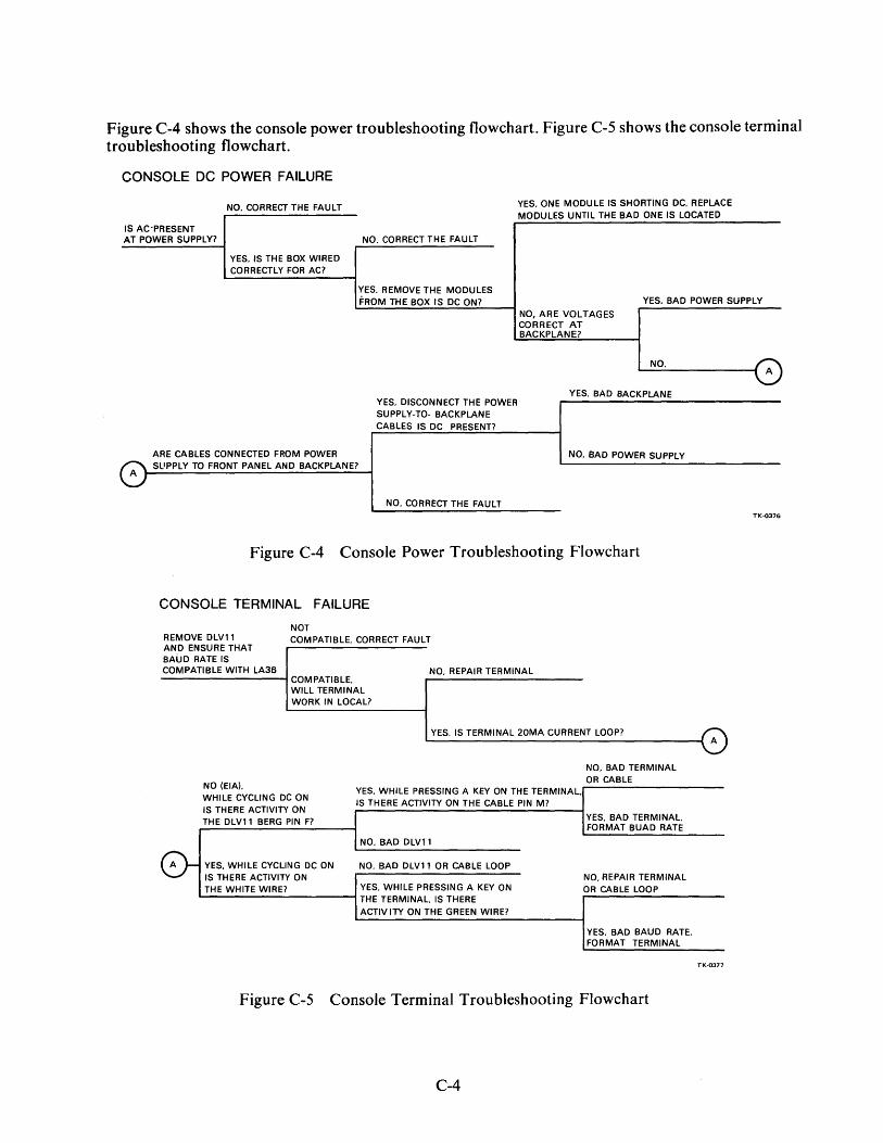
Figure C-4 shows the console power troubleshooting flowchart. Figure C-5 shows the console terminal troubleshooting flowchart.
CONSOLE DC POWER FAILURE
NO. CORRECT THE FAULT YES, ONE MODULE IS SHORTING DC, REPLACE MODULES UNTIL THE BAD ONE IS LOCATED
IS AC-PRESENT AT POWER SUPPLY? NO. CORRECT THE FAULT
YES. IS THE BOX WIRED CORRECTLY FOR AC?
YES, REMOVE THE MODULES FROM THE BOX IS DC ON? YES. BAD POWER SUPPLY
A
ARE CABLES CONNECTED FROM POWER SUPPLY TO FRONT PANEL AND BACKPLANE?
YES. DISCONNECT THE POWER SUPPLY-TO- BACKPLANE CABLES IS DC PRESENT?
NO. CORRECT THE FAULT
NO, ARE VOLTAGES CORRECT AT BACKPLANE?
NO.
YES. BAD BACKPLANE
NO. BAD POWER SUPPLY
Figure C-4 Console Power Troubleshooting Flowchart
CONSOLE TERMINAL FAILURE
NOT REMOVE DLVl 1 COMPATIBLE. CORRECT FAULT AND ENSURE THAT BAUD RATE IS COMPATIBLE WITH LA36 NO. REPAIR TERMINAL
COMPATIBLE. WILL TERMINAL WORK IN LOCAL?
YES. IS TERMINAL 20MA CURRENT LOOP?
0-i
NO (EIA) WHILE CYCLING DC ON
YES, WHILE PRESSING A KEY ON THE TERMINAL,
IS THERE ACTIVITY ON IS THERE ACTIVITY ON THE CABLE PIN M?
THE DLVl 1 BERG PIN F?
NO, BAD DLVl 1
YES, WHILE CYCLING DC ON NO. BAD DLVl 1 OR CABLE LOOP IS THERE ACTIVITY ON THE WHITE WIRE? YES. WHILE PRESSING A KEY ON
THE TERMINAL. IS THERE ACTIV ITV ON THE GREEN WIRE?
NO, BAD TERMINAL OR CABLE
YES. BAD TERMINAL, FORMAT BUAD RATE
NO, REPAIR TERMINAL OR CABLE LOOP
YES. BAD BAUD RATE, FORMAT TERMINAL
Figure C-5 Console Terminal Troubleshooting Flowchart
C-4
A
TK-0376
A
TK-0377

If use of the flowcharts fails to help in location of a problem, the RXDP package diagnostics can be run (diskette ZJ-215-RY).
Program Name
DVDVA DVDVC DVKAA DVKAD DVKAE DVKAH DZKMA DZLAC DZRXA DZRXB
Function
DLV-llE Test DLV-llF Test LSI-11 CPU Test LSI-11 Traps and Interrupts DLV-11 Test System Exerciser Memory Test LA36 Test Floppy Disk Exerciser Floppy Interface Tests
Figure C-6 shows the flow of events which develop on the LSI-11 boot sequence.
Note that ifthe LSI-11 program crashes while VMS is running, the operator may enter ODT and then type in 1413300 to reboot the console program without affecting VMS.
C-5
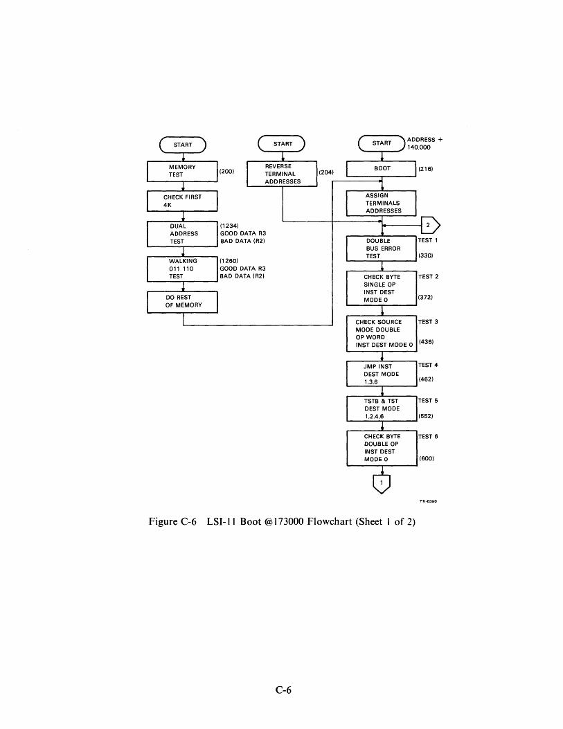
START
MEMORY TEST
CHECK FIRST 4K
DUAL ADDRESS TEST
WALKING 011 110 TEST
DO REST OF MEMORY
START
(200) REVERSE TERMINAL ADDRESSES
(1234) GOOD DATA R3 BAD DATA (R2)
(1260) GOOD DATA R3 BAD DATA (R2)
(204)
START
BOOT
CHECK BYTE SINGLE OP INST DEST MODE 0
ADDRESS+ 140.000
(216)
TEST 2
(372)
CHECK SOURCE TEST 3 MODE DOUBLE OP WORD INST DEST MODE 0 l435l
JMP INST DEST MODE 1.3.6
TSTB & TST DEST MODE 1.2.4.6 ,___ __ ___, ___ _.
CHECK BYTE DOUBLE OP INST DEST MODE 0
TEST 4
(462)
TEST 5
(552)
TEST 6
(600)
TK-0380
Figure C-6 LSl-11 Boot @173000 Flowchart (Sheet l of 2)
C-6
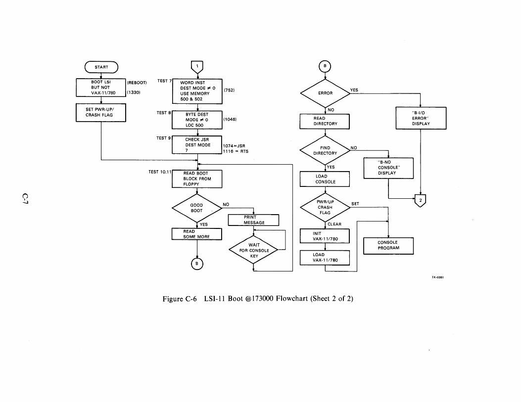
START
BOOT LSI (REBOOT) BUT NOT VAX-11/780 (1330)
SET PWR-UP/ CRASH FLAG
TEST 7
TEST 8
TEST 9
TEST 10.11
WORD INST DEST MODE¢ 0 USE MEMORY 500 & 502
BYTE DEST MODE¢ 0 LOC 500
CHECK JSR DEST MODE 7
READ BOOT BLOCK FROM FLOPPY
READ SOME MORE
(752)
(1046)
1074=JSR 1116 = ATS
NO
PRINT MESSAGE
READ DIRECTORY
INIT VAX-111780
LOAD VAX-111780
YES
NO
SET
Figure C-6 LSI-I I Boot @I 73000 Flowchart (Sheet 2 of 2)
"B-NO CONSOLE" DISPLAY
CONSOLE PROGRAM
"B-110 ERROR" DISPLAY
2
TK-0381

VAX-11/780 DIAGNOSTIC SYSTEM USER'S GUIDE EK-DS780-UG-002
Reader's Comments
Your comments and suggestions will help us in our continuous effort to improve the quality and usefulness of our publications.
What is your general reaction to this man~al? In your judgment is it complete, accurate, well organized, well written, etc.? Is it easy to use? ----------------------------
What features are most useful? ___________________________ _
What faults or errors have you found in the manual?--------------------
Does this manual satisfy the need you think it was intended to satisfy? -------------
Does it satisfy your needs? ____________ _ Why? ________________ _
D Please send me the current copy of the Technical Documentation Catalog, which contains information on the remainder of DIGITAL's technical documentation.
Name ---------------------Title ----------------Company _________________________ _
Department ----------------------
Street ---------------------
City --------------------State/Country -------------Zip
Additional copies of this document are available from:
Digital Equipment Corporation 444 Whitney Street Northboro, Ma 01532 Attention: Communications Services (NR2/M15)
Customer Services Section
Order No. _E_K_-_D_S7_8_0_-U_G_-0_0_2 _____ _

- - - - - - - - - - - Foldffere - - - - - - - - - - -
- - - -- -- -- -- -- Do Not Tear - Fold Here and Staple
BUSINESS REPLY MAIL FIRST CLASS PERMIT NO. 33 MAYNARD, MA.
POSTAGE WILL BE PAID BY ADDRESSEE
Digital Equipment Corporation Educational Services Development and Publishing 1925 Andover Street Tewksbury, Massachusetts 01876
No Postage
Necessary
if Mailed in the
United States