volkswagen r32 - vwcup-files.track360.com
TRANSCRIPT

Self-Study Program
Course Number 89C303
Volkswagen R32

Volkswagen of America, Inc.Service TrainingPrinted in U.S.A.Printed 4/2004Course Number 89C303
©2004 Volkswagen of America, Inc.
All rights reserved. All information contained in thismanual is based on the latest information available atthe time of printing and is subject to the copyrightand other intellectual property rights of Volkswagen ofAmerica, Inc., its affiliated companies and itslicensors. All rights are reserved to make changes atany time without notice. No part of this documentmay be reproduced, stored in a retrieval system, ortransmitted in any form or by any means, electronic,mechanical, photocopying, recording or otherwise,nor may these materials be modified or reposted toother sites without the prior expressed writtenpermission of the publisher.
All requests for permission to copy and redistributeinformation should be referred to Volkswagen ofAmerica, Inc.
Always check Technical Bulletins and the VolkswagenWorldwide Repair Information System for informationthat may supersede any information included in thisbooklet.
Trademarks: All brand names and product namesused in this manual are trade names, service marks,trademarks, or registered trademarks; and are theproperty of their respective owners.

i
Introduction . . . . . . . . . . . . . . . . . . . . . . . . . . . . . . . . . . . . . . . . . . . . . . . . .1Overview, Highlights, Other Technical Features, Distinguishing Exterior Features,Distinguishing Interior Features
3.2L V6 Engine . . . . . . . . . . . . . . . . . . . . . . . . . . . . . . . . . . . . . . . . . . . . . .10
Overview
Haldex Coupling . . . . . . . . . . . . . . . . . . . . . . . . . . . . . . . . . . . . . . . . . . . . .12Haldex System, Multi-Plate Clutch, Diagram of the Oil Pressure System, MotronicEngine Control Module (ECM) J220, Engine Speed (RPM) Sensor G28, Throttle PositionSensor G79 and Sender 2 for Accelerator Pedal Position G185, ABS Control ModuleJ104, Right Rear and Left Front ABS Wheel Speed Sensors G44 and G47, ESP SensorUnit G419, Brake Light Switch F, Parking Brake Warning Light F9, HydraulicTemperature Sensor G271, All-Wheel Drive (Haldex) Control Module J492, Oil PressureActuator V184, Haldex Clutch Pump V181, Self-Diagnosis
Electronic Differential Lock . . . . . . . . . . . . . . . . . . . . . . . . . . . . . . . . . . . .37
Suspension and Brakes . . . . . . . . . . . . . . . . . . . . . . . . . . . . . . . . . . . . . . .39
Suspension, Brakes
Exhaust System . . . . . . . . . . . . . . . . . . . . . . . . . . . . . . . . . . . . . . . . . . . . .42
Overview, Switchable Exhaust Flap
Specifications . . . . . . . . . . . . . . . . . . . . . . . . . . . . . . . . . . . . . . . . . . . . . . .46
Knowledge Assessment . . . . . . . . . . . . . . . . . . . . . . . . . . . . . . . . . . . . . . .49
Table of Contents
Note

II

1
Introduction
Overview
The 2004 R32 (“R” = Racing) is the mostpowerful Golf to date, thanks to a new andvery responsive 240 hp 3.2-liter V6 enginewhich delivers 236 lb/ft of torque at 2800 to3200 rpm. Volkswagen’s 4Motion all-wheeldrive system ensures complete and efficientuse of all this power, ensuring that most ofthe R32’s peak torque is delivered at lessthan 3000 rpm.
The Golf GTI was the original “pocketrocket,” mating a powerful selection ofengines to a lightweight chassis. The GTIremains a great sports car, with the R32taking the “more explosive power in a smallpackage” theme up a notch with 20% morepower and a host of luxury sports carfeatures.

Highlights
A dual exhaust and chrome-plated tailpipesystem, coupled with a switchable exhaustflap in the rear silencer produces a powerfulengine sound in keeping with theperformance qualities of the 3.2L V6.
The transverse drivetrain R32 uses adifferent 4Motion system than the systemsequipped on the longitudinal drivetrainPhaeton, Touareg, and Passat. Instead ofusing a Torsion center differential to controland deliver power to all four wheels, R32uses a high-performance Haldex clutch atthe rear axle to accomplish the same tasks.
Introduction
2

3
The 02M 6-speed manual transmissionfeatures closer spaced gear ratios, shortershift travel, and a modified selector fork andselector rod. This combination ensures thatthe engine is always in its maximum torquecurve while also ensuring quicker, moreresponsive shifts in every gear.
Introduction

Introduction
4
Other Technical Features
• MacPherson suspension struts andlower wishbones at the front
• New independent 4-link rear suspensionwith forged dual-link trailing arms andBilstein rubber vibration dampers thataccommodate the 4Motion all-wheeldrive system
• Larger H&R springs painted “Jazz Blue”
• Reinforced front axle and sway bars,including large diameter rear anti-rollbar, subframe, transverse link, andconnecting links
• Large diameter rear anti-roll bar
• Extended steering rack travel and moreteeth on the pinion for more responsivehandling
• Larger 2FN dual piston brake systemwith floating frame calipers and two-piece ventilated directional rotorspainted “Jazz Blue”
• MK60 Anti-Lock Brake System (ABS)
• Electronic Stabilization Program (ESP)
Rear Suspension
Front Brake System

5
Introduction
Distinguishing Exterior Features
• Three honeycomb ventilation grilles inthe lower section of the larger andlower front spoiler/valance
• Larger and lower rear bumper/valance
• Hatch spoiler
• Modified side sills
• A ride height 20 mm lower than astandard Golf, and 10 mm lower thanthe GTI VR6

Introduction
6
Distinguishing Exterior Features
(continued)
• 15-spoke “OZ Aristo” racing-design 18-inch light alloy wheels with wheel locks,specially designed to provide optimumcooling for the brake system
• Low profile 225/40 ZR 18-inch summertires
• The combination of lower ride height,larger front spoiler and sills, and lowprofile tires give the appearance of thewheels and tires filling the wheelarches
• Power tilt/sliding sunroof
• R32 badging on the radiator grille andtailgate
• Heated rearview mirrors
• Darkened tail lights and exclusive blue-tinted heat-insulating windows
• Initial introduction is with the two-doormodel, to be followed by a four-doorversion

7
Introduction
Distinguishing Interior Features
• A new molded, ergonomic 3-spokeleather steering wheel with R logo
• Heated Koenig front sport seatsincluding racing-design side cushionsand integrated front head restraints,plus the embossed R logo
• Split rear seats with the embossed Rlogo (rear seats can be folded down)

Introduction
8
Distinguishing Interior Features
(continued)
• Leather gearshift boot and brushedaluminum gearshift knob with R and4Motion logos
• Modified instrument cluster featuringchrome trim rings on the roundinstruments and a speedometer thattops out at 180 mph (actual R32 topend is governed at 130 mph)
• Alloy pedals with rubber insertsincorporating the R logo
• Alloy side foot rest

9
Introduction
Distinguishing Interior Features
(continued)
• Door sill moldings with brushedaluminum inlay and R32 logo
• Brushed aluminum door handles andother interior components
• Front and side airbags for both driverand passenger
• Climatronic electronic climate controlsystem
• Multi-function indicator
• Rain sensing system
• Automatic “auto dimming” interiormirror
• Monsoon sound system, with PremiumVI radio/CD/cassette
• Anti-theft alarm with interior motionsensor and back-up horn
• Power windows
• Tire Mobility repair kit in place of aspare tire

10
3.2L V6 Engine
To make best use of this increaseddisplacement, the entire intake system wasredesigned to improve torque and power.This was done by altering the flow geometryof the plastic intake manifold and the ductsin the cylinder head.
Overview
Volkswagen’s 3.2L 15-degree V6 four-valveengine is a powerful evolution of thecompact and proven 2.8L VR6 engine.Horsepower numbers were increased from200 to 237 hp, with torque increasing from195 to 236 lb/ft at just 2800 to 3200 rpm.
The increased engine capacity was achievedby extending piston stroke (81.0 to 84.0 mm)and increasing the size of the cylinder bores(90.3 to 95.9 mm). The compression ratiowas also increased from 10.5 : 1 to 11.3 : 1.

11
There are seven main bearings on thecrankshaft. Ancillaries were adopted fromthe 2.8L VR6.
The 3.2L V6’s software had to be adapted tothe special requirements of the R32. Thisincluded improving response characteristicsand matching the engine software to thespecial dual-pipe exhaust system with itstwo catalytic converters.
3.2L V6 Engine
The 3.2L V6’s valves are actuated by rollerrocker fingers with hydraulic clearancecompensation. Oil fed adjusters providecontinuous adjustment of the inlet andexhaust camshafts, 52 degrees for the intakeside and 22 degrees for the exhaust cam.
The 3.2L V6’s variable valve timingovercomes the limitations of static valvetiming by altering the points in the four-strokecycle when the valves open and close. Thisallows the engine to produce higher torquethrough a wider rpm range.
Technical Data
3.2L V6 Type: DOHC 15-degree 6-cylinder gasoline
engine with continuous adjustment of both intake and exhaust cams, and 4 valves per cylinder
Displacement: 3.2 liters
Bore and Stroke: 84.0 x 95.9 mm
Compression Ratio: 11.3 : 1
Power: 240 hp @ 6250 rpm
Torque: 236 lb/ft @ 2800-3200 rpm

12
Haldex Coupling
Characteristics of the Haldex coupling:
• Permanent all-wheel drive withelectronically controlled multi-plateclutch
• Front drive characteristic
• Quick response
• No strain on clutch when parking andmaneuvering vehicle
• Compatible with different tires (e.g.,emergency wheel)
• No restrictions on towing with the rearaxle on the ground
• Fully integrates with systems such asthe Anti-Lock Brake System (ABS),Electronic Differential Lock (EDL), Anti-Slip Regulation (ASR), ElectronicBrake Distribution system (EBD), andElectronic Stabilization Program (ESP)
The development of the Haldex coupling is agiant step forward in modern all-wheel-drivetechnology. This coupling is controllable,based on the inputs the Haldex controlmodule receives from the vehicle.
Slip is no longer the only decisive factor inthe distribution of drive forces — the car’sdynamic state is also a factor. The Haldexcontrol module monitors the ABS wheelspeed sensors and the engine controlmodule (accelerator pedal signal) via theCAN-bus. This data provides the enginecontrol module with all the information itneeds on road speed, cornering, coasting ortraction mode, and can respond optimally toany driving situation.
Haldex Coupling

13
The Haldex coupling is mounted on the rearaxle differential and is driven by the driveshaft.
Engine torque is transmitted to the driveshaft through the gearbox, the front axledifferential, and the front axle drive
The drive shaft is connected to the inputshaft of the Haldex coupling. In the Haldexcoupling, the input shaft is separated fromthe output shaft to the rear axle differential.
Torque can only be transmitted to the rearaxle differential when the Haldex couplingclutch plates are engaged.
Haldex Coupling
Rear Differential
Haldex Coupling
Drive Shaft
RearDifferential
Transmission
HaldexCoupling
DriveShaft

14
Haldex System
The parts include:
• Input shaft
• Inner and outer clutch plates
• Lifting plate
• Roller bearing with annular piston
• Output shaft
Haldex Coupling
The electronics are:
• Pump for Haldex coupling
• Regulating valve positioning motor
• Temperature sensor
• Haldex control module
The hydraulics are:
• Pressure valves
• Accumulator
• Oil filter
• Annular piston
• Regulating valve
The Haldex oil and oil filter must bereplaced every 20,000 miles (32,000km). Refer to VESIS for the latestmaintenance schedules and serviceprocedures.
Lifting Plate
Clutch Plates
Output Shaft
Pressure Limiting ValveAccumulator
Input Shaft
Annular Piston
Electric Pump
Oil Filter
Control Module
Regulating ValvePositioning Motor
Regulating Valve
TemperatureSensor

15
Multi-Plate Clutch
The clutch input shaft, indicated in blue inthe illustration below, is connected to theprop shaft. The roller bearings for the liftingpiston and the working piston, as well as theouter clutch plates, are engaged when theinput shaft rotates.
Haldex Coupling
The lifting and working pistons are annularpistons. The output shaft, indicated in red inthe figure, forms a unit from the lifting platethrough to the drive pinion head. The innerclutch plates are also connected to theoutput shaft via longitudinal toothing.
Outer Clutch Plate Roller Bearing forWorking Piston
Working Piston
Roller Bearing forLifting Piston
LiftingPiston
Inner Clutch Plate
Input Shaft
Lifting Plate
Disengaged Haldex Clutch Assembly
Drive Pinion Head
Output Shaft

16
Haldex Coupling
Oil pressure is diverted via an oil duct to theworking piston, forcing the working piston tomove to the left against the roller bearingsand the pressure plate of the clutch plateset.
The clutch plate set is compressed.
The input shaft and the output shaft of theclutch are now interconnected, connectingboth the front and rear axles and making all-wheel drive possible.
Pressure Plate
Clutch Plate Set
Output Shaft
Oil Duct
Input Shaft
Lifting Plate
Engaged Haldex Clutch Assembly
Function
When a speed difference is presentbetween the input and output shafts, theinput shaft, together with the roller bearingof the lifting piston, rotates around the stillstationary lifting plate of the output shaft.
The roller bearing of the lifting piston tracksalong the undulating surface of the liftingplate. The roller transfers these upward anddownward movements to the lifting piston,causing it to perform a lift movement,building up oil pressure.

17
Haldex Coupling
When a difference in speeds occursbetween the front and rear axles, the outerclutch plate housing, together with the rollerbearings, rotates around the output shaft insuch a way that the roller bearings of thelifting piston roll on the lifting plate.
Due to the shape of the lifting plate, theroller bearings of the lifting piston follow anundulating path and transfer the liftingmovement to the lifting pistons in thehousing.
The output shaft, with its splines for theinner clutch plate, combines with the liftingplate and the drive pinion head to form aunit.
The roller bearings are shown herefor your information only.
For reasons of clarity, we haveshown the lifting plate with twocams. In reality, there are threecams on the lifting plate. Thefunction remains unchanged.
Roller Bearing forWorking Piston
Roller Bearing forLifting Piston
Drive Pinion Head
Inner Clutch Plate
Engaged Haldex Clutch Assembly
Lifting Plate

18
The outer clutch plate housing, togetherwith the splines for the outer clutch plateand roller bearings, combine with the inputshaft to form a unit.
The movement of the lifting piston producesan oil pressure which acts on the workingpiston via the oil duct, pushing the piston tothe left.
Haldex Coupling
Pressure is transferred via a pressure plateto the clutch plate set and the roller bearingsof the working piston. The clutch closes andthus interconnects the front and rear axles.
The roller bearings are located in theouter clutch plate housing, as shownhere. These roller bearings areshown here for your informationonly.
Oil Duct
Lifting Piston
Outer ClutchPlate Housing
Splines
Input Shaft
Working Piston
Clutch Housing

19
Diagram of the Oil Pressure System
The pressure limiting valve determines themaximum pressure on the clutch plates.
You have already seen how oil pressure isbuilt up at the lifting piston as a result of adifference in speeds between the input shaft(blue) and the output shaft with lifting plate(red).
Haldex Coupling
This oil pressure is regulated by valves. Theclutch plate can thus allow a certain amountof slip when open and nearly closed.
For reasons of clarity, we explained function on the previous pages using a lifting pistonby way of an example. In reality, there are two lifting pistons in the clutch housing —these pistons are actuated by roller bearing pairs. Therefore, two suction valves and twopressure valves are also required.
PositioningMotor
RegulatingValve
PressureLimiting
Valve
PressureValves
RollerBearing
PairLiftingPlate
Bearing
ClutchPlate Set Working
Piston
LiftingPistonPump Suction
Valves
Filter
Pump Strainer
Accumulator

20
Haldex Coupling
Engine Speed(RPM) Sensor G28
Throttle PositionSensor G79
Right and LeftRear ABS WheelSpeed SensorsG44 and G47
Sender 2 forAccelerationPedal PositionG185
Motronic Engine ControlModule (ECM) J220
ESP SensorUnit G419
Brake Light Switch F
Parking BrakeWarning LightSwitch F9
ABS Control Module(with EDL) J104

21
Haldex Coupling
Hydraulic TemperatureSensor G271
Parking BrakeWarning Light
Switch F9
All-Wheel Drive(Haldex) Control
Module J492
Haldex ClutchPump V181
Diagnosis PlugConnection
Oil Pressure ActuatorV184 (Positioning
Motor)

22
Haldex Coupling
Motronic Engine Control Module
(ECM) J220
This control module is mounted in differentareas on the various vehicles, but is normallyaccommodated in the plenum chamber. Theoperating mode of J220 is torque-oriented.
Signal Utilization for the All-Wheel Drive
Electronics
J220 provides the following signals to theAll-Wheel Drive (Haldex) Control ModuleJ492 along the CAN-bus:
• Engine speed signal
• Accelerator pedal position
• Engine torque
Effects of signal failure:
• The Haldex coupling will not operate
Motronic Engine Control Module (ECM) J220

23
Engine Speed (RPM) Sensor G28
G28 is an inductive sensor and is installednear the oil filter on the left-hand side of theengine.
Signal Utilization
This sensor records in the exact angularposition of the crankshaft to determine theignition and injection point, as well as enginespeed.
Engine Speed
As soon as the engine turns, the sensorwheel moves past G28 and generates analternating current (AC) voltage. Thefrequency and amplitude of this voltagechanges with engine speed.
Motronic ECM J220 calculates engine speedfrom the frequency of the AC voltage.
Ignition Point
To recognize crankshaft position, the sensorwheel has a larger gap trigger tooth whichserves as a reference mark.
Effects of Signal Failure
If the engine speed signal supplied by G28fails, the engine will not start or run.
If no engine speed signal is received, theHaldex control module J492 will notenergize the pump, leaving rear axle drivecapability disabled. This also allows thevehicle to be towed with the rear wheels onthe ground because no power is transmittedback through the wheels to thetransmission.
Haldex Coupling
J220
Engine SpeedSensor G28
Sensor Wheel
G28

24
Throttle Position Sensor G79 and
Sender 2 for Accelerator Pedal
Position G185
Two independent potentiometers, G79 andG185, work together to receive and sendaccelerator pedal position analog signals toMotronic ECM J220.
Haldex control module J492 uses thesesignals in combination with other signals todetermine when and how much powershould be applied to the rear axle. G79 andG185 represents the driver intention, and isnot necessarily how J220 is allowing theengine to operate.
Effects of Signal Failure
J220 monitors G79 and G185 for properfunctioning and plausibility. If one of thesetwo fails, the other sensor/sender acts as aback-up. The Electronic Power Control (EPC)Warning Lamp K132 on the instrumentcluster will illuminate and the vehicle willenter emergency running mode.
If this signal is not available to the Haldexcontrol module J492, all-wheel drive will notbe available.
Haldex Coupling
Accelerator Pedal PositionSensor/Sender G79/G185

25
Haldex Coupling
ABS Control Module J104
This control module is combined with thehydraulic unit, which is mounted in theengine compartment on the left-hand side.When the ignition is turned on, the controlmodules carry out a self-test.
This control module consists of twoprocessor systems, which ensures a highlevel of fail-safety. In addition to monitoringindividual components, the two processorsystems monitor each other.
Signal Utilization for All-Wheel-Drive
Electronics
The following signals are supplied to theHaldex control module J492 along the CAN-bus:
• ABS Wheel Speed Sensors G44 andG47
• Brake Light Switch F9
• Parking Brake Light Switch F9
• Longitudinal Acceleration Sensor G251
Effects of Signal Failure
In the unlikely event of total failure of thecontrol module, the Haldex unit will notfunction properly.
HydraulicBrake Unit
ABS Control Module(with EDL) J104

26
Haldex Coupling
Right Rear and Left Front ABS
Wheel Speed Sensors G44 and G47
These sensors detect changes in wheelspeed, sending this information to ABSControl Module J104 in the form of wheelspeed information. This information is thensent to Haldex control module J492 viaCAN-bus.
Each wheel speed sensor is mounted in thevicinity of the axle flange. A toothed wheelis positioned on the axle flange in such away that it moves past the top end of thewheel speed sensor when the wheelrotates.
Magnetic lines of force between the toothand tooth gap of the toothed wheel aredistorted. This induces a sine-wave ACvoltage in the coil of the engine speedsensor.
The frequency and amplitude in the coil isdependent on wheel speed. J104 calculatesthe momentary speed of individual wheelsfrom the frequency.
Effects of signal failure:
• No ABS control
• No all-wheel drive control
ABS WheelSpeed Sensor
ToothedWheel

27
ESP Sensor Unit G419
ESP Sensor Unit G419 combines thefunctionality of two sensors, Sensor forTransverse Acceleration G200 and Sensor forRotation Rate G202. This combined sensor islocated on a bracket in the steering columnarea, under the instrument cluster. G419 isable to measure both transverseacceleration and rotational rate or yaw.
Effects of Signal Failure
Without the measurement of transverseacceleration or rotational rate, it is notpossible for the ABS Control Module J104 todetermine if ESP intervention is necessary.As a result, ESP and ASR will not operate,and the ESP light will illuminate in theinstrument cluster.
Electrical Circuit
G419 is connected to J104 via four wires.
Haldex Coupling
ESP Sensor Unit G419 LocatedUnder the Instrument Panel
28
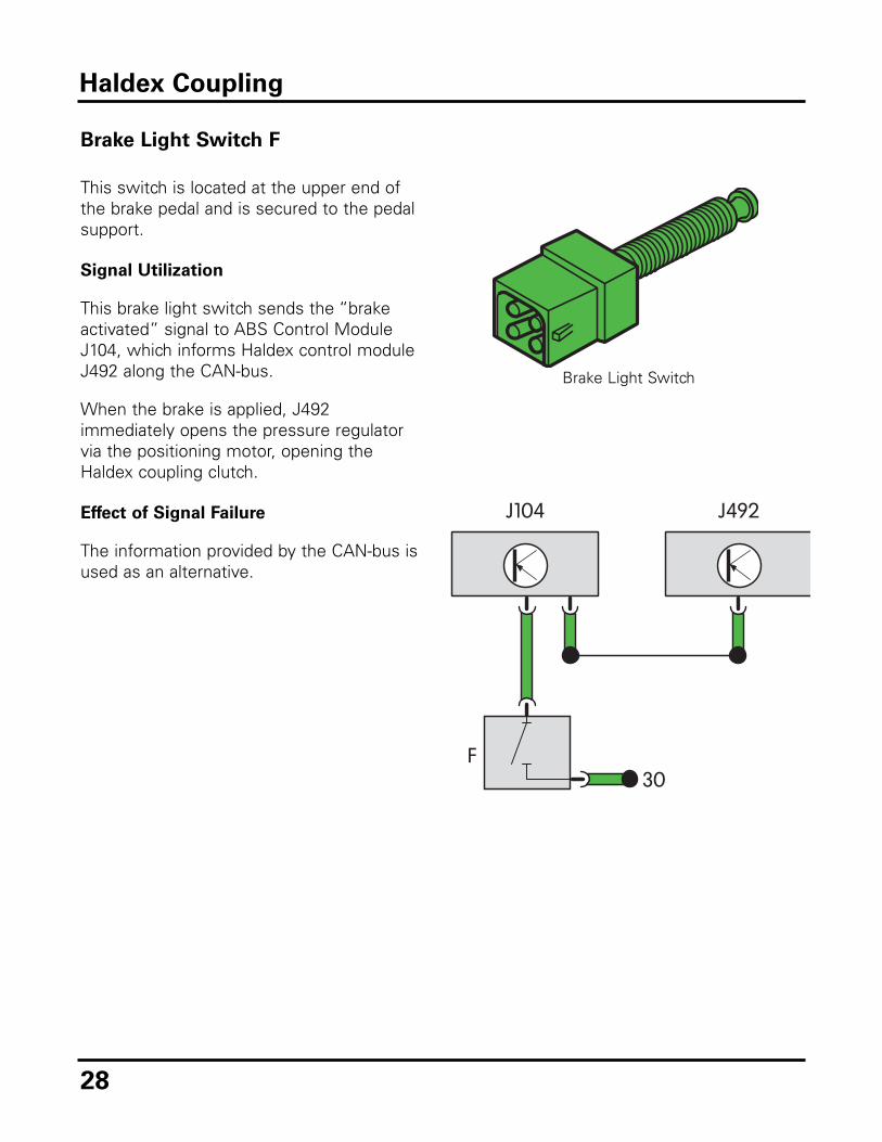
Brake Light Switch F
This switch is located at the upper end ofthe brake pedal and is secured to the pedalsupport.
Signal Utilization
This brake light switch sends the “brakeactivated” signal to ABS Control ModuleJ104, which informs Haldex control moduleJ492 along the CAN-bus.
When the brake is applied, J492immediately opens the pressure regulatorvia the positioning motor, opening theHaldex coupling clutch.
Effect of Signal Failure
The information provided by the CAN-bus isused as an alternative.
Haldex Coupling
Brake Light Switch

29
Parking Brake Warning Light F9
This switch is located under the parkingbrake lever.
Signal Utilization
F9 sends the “parking brake engaged”signal simultaneously to ABS ControlModule J104 and the Haldex control moduleJ492.
If the signal generated by F9 is picked up,the Haldex coupling clutch is opened.
Effects of Signal Failure
If the switch remains closed, then no all-wheel drive control is available andrestrictions are placed on ABS control.
Haldex Coupling
Parking Brake Warning Light Switch F9

30
Hydraulic Temperature Sensor G271
This sensor is installed near the regulatingvalve in the Haldex control module J492housing and is immersed in hydraulic fluid.
Signal Utilization
G271 senses current hydraulic oiltemperature, sending this information toJ492. This information is used for constantadaptation to the changing hydraulic fluidviscosity.
If the hydraulic fluid temperature exceeds100°C, the clutch is released. If thetemperature of the hydraulic fluid dropsbelow 100°C, the clutch is again pressurized.
Effects of Signal Failure
All-wheel drive is shut off if no signal isreceived from G271.
Haldex Coupling
Temperature Hydraulic Fluid/Viscosity Regulating Valve In the minus range High viscosity Slightly more open Normally 20°C Normal Normally open Over 20°C Low viscosity Slightly less open
Hydraulic Temperature Sensor G271

31
All-Wheel Drive (Haldex)
Control Module J492
This control module is mounted directly onthe housing of the Haldex coupling andcombines with the positioning motor andthe regulating valve to form a unit.
Design and Function
J492 is connected to the engine and ABScontrol module J104 via the CAN-bus. Fromthe signals that are generated by MotronicECM J220 sensors, J492 decides what oilpressure to apply to the plates of the Haldexcoupling clutch.
The oil pressure acting on the plates of theHaldex coupling clutch determine whattorque is to be transmitted to the rear axle.
Effects of Signal Failure
If J492 is not operating correctly, noall-wheel drive is possible.
Haldex Coupling
Use address word 22 to accessAll-Wheel Drive (Haldex) ControlModule J492.
Haldex Control Module J492

32
Oil Pressure Actuator V184
This positioning motor is integrated in theHaldex control module J492 housing.
Design and Function
V184 is supplied with voltage by J492 andfunctions as a stepping motor.
At the command of J492, the positioningmotor changes the level of the regulating pinin the pressure regulator via a small piniongear.
The level of the regulating pin changes thecross section of a return bore in thepressure regulator. This controls thepressure acting on the working piston, andin turn, on the clutch plates.
Regulator closed:
• Maximum pressure on clutch plates
Regulator partially open:
• Reduced pressure on clutch plates
Regulator fully open:
• No pressure on clutch plates
Haldex Coupling
PositioningMotor V184
Pinion
Return Bore
Regulating Valve
Regulating Pin

33
Haldex Clutch Pump V181
The pump for the Haldex coupling isattached to the Haldex coupling housing.
Design
After the engine has been started, the pumpfor the Haldex coupling is supplied withvoltage by Haldex control module J492 assoon as engine speed exceeds 400 rpm.
Function
The pump for the Haldex clutch conveys oilto the lifting piston and brings the liftingpiston into contact with the lifting plate viaroller bearings.
At the same time, oil reaches the workingpiston. This eliminates any play from theclutch plate set and ensures quick clutchresponse.
Effects of Signal Failure
If V181 is not operating correctly, no all-wheel drive is possible.
Haldex Coupling
The Haldex clutch pump is directlysupplied with voltage by J492.
Haldex Clutch Pump

34
Haldex Coupling
Parking Acceleration High-SpeedDriving
Difference in speed betweenfront and rear axles
Low High Low
Torque required at therear axle
Low High Low
Condition of multi-plate clutch Low contactpressure
High contactpressure, up tomaximum, EDL
control system canincrease contact
pressure
Closed, as required
Input signals • Engine torque• Engine speed• Accelerator
pedal position• Four wheel
sensors
• Engine torque• Engine speed• Accelerator
pedal position• Four wheel
sensors
• Engine torque• Engine speed• Accelerator
pedal position• Four wheel
sensors

35
Haldex Coupling
Slippery Surfaces Emergency WheelInstalled
Braking Towing
Fluctuates betweenlow and high
Normal to high Normal to high High
Fluctuates betweenlow and high
Low 0 0
Closed, up tomaximum
Open, or slightlyclosed
Open Open, electricalpre-pressure pump is off when ignition
is off
• Engine torque• Engine speed• Accelerator pedal
position• Four wheel
sensors• CAN-bus
communication
• Four wheelsensors
• via ABS controlmodule
• Four wheelsensors
• via ABS controlmodule
• Brake light switch
• Engine speed lessthan 400 rpm

36
Self-Diagnosis
Haldex self-diagnosis electrically monitors:
• Signals generated by the sensors
• Activation of the positioning motors
• Haldex control module J492
If J492 detects a fault, it calculates asubstitute value from other signals andmakes an emergency running programavailable.
In the data transfer facility, the followingfunctions can be read out under the addressword 22 “4-wheel-drive electronics” via theVAS 5051 or VAS 5052:
02 Check DTC Memory
03 Output Diagnostic Test Mode (DTM)
05 Erase DTC Memory
06 End Output
08 Read Measuring Value Block
Haldex Coupling

37
Electronic Differential Lock (EDL)
Traction Control
Electronic Differential Lock (EDL) uses thesame sensors and components that theAnti-Lock Brake System (ABS) uses tocontrol traction.
The wheel speed sensors send informationto the ABS Control Module J104. Whenthere is a difference in wheel speeds, theEDL function will apply the brakes to thewheel that is spinning, to control slip. Whenbrakes are applied to the wheel that isspinning, power will automatically be sentthrough the differential to the wheel that hastraction.
For example, if the vehicle is on a largepatch of ice and only one wheel has traction,EDL will pump the brakes of the wheels thatare spinning.
Without EDL
With EDL
38
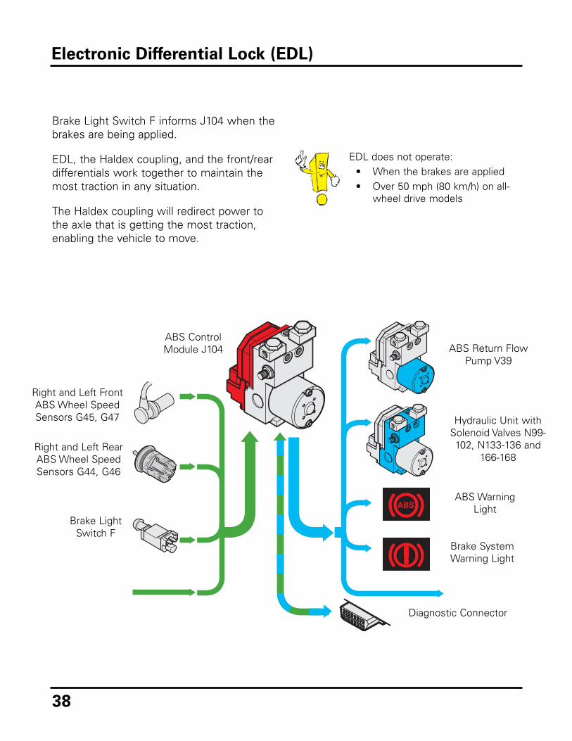
Electronic Differential Lock (EDL)
Brake Light Switch F informs J104 when thebrakes are being applied.
EDL, the Haldex coupling, and the front/reardifferentials work together to maintain themost traction in any situation.
The Haldex coupling will redirect power tothe axle that is getting the most traction,enabling the vehicle to move.
EDL does not operate:• When the brakes are applied• Over 50 mph (80 km/h) on all-
wheel drive models
ABS Return FlowPump V39
ABS ControlModule J104
Brake SystemWarning Light
ABS WarningLight
Hydraulic Unit withSolenoid Valves N99-102, N133-136 and
166-168
Right and Left FrontABS Wheel SpeedSensors G45, G47
Right and Left RearABS Wheel SpeedSensors G44, G46
Brake LightSwitch F
Diagnostic Connector

39
Suspension and Brakes
Suspension
The layout of the Golf’s running gear hasinfluenced whole generations of compactclass cars since the series was launched.This is especially true of the R32. ItsMacPherson struts and lower wishbones onthe front axle make it one of the most highlyregarded axle systems on the market.
To accommodate the 4Motion Haldexsystem, the R32 has a 4-link fullyindependent rear suspension. The wheellocation is provided by a multilinkconstruction with forged dual-link trailingarm suspension. This is mounted on asubframe and coupled to the running gearvia rubber vibration dampers.
The rear axle subframe has a very flatdesign to maximize available space insidethe R32. The separate layout of the springsand shock absorbers preserves the springcharacteristic of the front drive vehicle andthe interior width.

40
The front sway bars and rear anti-roll barhave been significantly strengthenedcompared to those on GTI, 19 to 23 mm inthe front, and 16 to 19 mm at the rear axle.
This suspension package results inmaximum steering precision and clearlydefined handling with excellent corneringstability.
Suspension and Brakes
Front Suspension
Rear Suspension
Sway Bar

41
Suspension and Brakes
Brakes
Given the step up in horsepower and torque,it was necessary to add larger, moreresponsive brakes to the R32 package.
The result was a 2FN dual piston brakesystem with floating frame calipers and two-piece ventilated directional rotors. The frontbrake caliper is the same as that used onthe Passat W8.
The front discs are 334 mm (13.14 inches),with the rear discs at 256 mm (10.07inches).
Front Brake System
Rear Brake System

42
Overview
The R32 features a dual pipe exhaustsystem: a front pipe, two catalyticconverters in a single housing, and twoexhaust pipes leading to two chromedtailpipes. The front exhaust pipe has a largercross-sectional ratio than the dual pipes,which have been designed to optimizeexhaust gas back pressure.
The two catalytic converters are housedinside a one-piece welded stainless steelprotective shield. A connector station forfour oxygen sensors is also part of theemissions control system.
Exhaust System
Connector Station for Four Oxygen Sensors
Twin Catalytic ConvertersDual Tailpipes
One of Four Exhaust System Oxygen Sensors
Oxygen Sensor

43
This dual pipe system not only assists theengine in meeting emissions standards, butit also contributes a strong throaty responsewhen accelerating.
At speeds exceeding 40 mph, a switchableexhaust flap in the rear silencer richens the3.2L V6 engine sound exiting the twochrome tailpipes.
Exhaust System
Rear Silencer with Exhaust Flap

44
Switchable Exhaust Flap
Speed actuated, this flap automaticallydeploys at approximately 40 mph to increaseexhaust sound from 75dB to a more robust84dB.
The flap is opened at the rear silencer toincrease the flow cross section of theexhaust gas via a bypass pipe.
Actuation takes the form of a pulse from theMotronic Engine Control Module (ECM)J220 to a solenoid-operated valve. Thispermits passage of the intake manifoldvacuum via a vacuum reservoir to a vacuumadjuster. In the adjuster, this vacuumactuates a diaphragm which acts directly onthe flap via a lever and thus opens up theadditional flow cross section in the rearsilencer.
Exhaust System
Vacuum Reservoir

45
The vacuum reservoir unit at the rear of thevehicle, consists of the vacuum reservoir,non-return valve, and solenoid-operatedvalve, is fitted above the rear silencer at thelongitudinal member.
The vacuum pipe is incorporated into theinterior harness. It starts at the back of theengine compartment, travels along theunderside of the vehicle, and completes itsjourney at the vacuum reservoir.
Exhaust System
InteriorHarness
VacuumPipe
VacuumHose
PipeAssembly
Back of Engine Compartment
For the sake of clarity, the muffler hasbeen removed in the graphic above.
CombiHolder
Clamps
VacuumReservoir
Harness WithVacuum Pipe
Vacuum Hose toExhaust Flap atRear Silencer

46
Specifications
ENGINE Type 6 cylinder, 15° V, gasoline Bore 3.31 in 84.0 mm Stroke 3.78 in 95.9 mm Displacement 194.6 in3 3189 cm3
Compression Ratio 11.3 : 1 Horsepower (SAE) @ rpm 240 @ 6250 Maximum Torque, lb/ft @ rpm 236 @ 2800-3200 Fuel Requirement Premium unleaded recommended for maximum performance Firing Order 1-5-3-6-2-4 ENGINE DESIGN Arrangement Front-mounted, transverse Cylinder Block Cast iron Crank Shaft Forged steel, seven main bearings Cylinder Head Aluminum alloy, cross flow Valve Train Dual overhead camshaft, chain driven, four valves per
cylinder, maintenance free hydraulic lifters, variable valve timing
Cooling System Water cooled, water pump, cross flow radiator, thermostatically controlled electric 3-speed radiator fan
Lubrication Rotary gear pump, oil cooler Fuel / Air Supply Sequential multi-port fuel injection (Motronic), variable intake
manifold, variable intake and exhaust cam timing Emissions LEV I California Emissions Concept, Bin 9 EPA Federal
Emissions Concept, OBD II, ORVR (onboard refueling vapor recovery), 3-way catalytic converter with oxygen sensor, secondary air injection pump
ELECTRICAL SYSTEM Alternator — V/A 14/120 Battery — V/A 12/70 Ignition Digital electronic with dual knock sensor DRIVETRAIN Drivetrain 4Motion permanent all-wheel drive system (Haldex) Transmission Manual Automatic
1st 3.36 — 2nd 2.09 — 3rd 1.47 — 4th 1.10 — 5th 0.86 — 6th 0.72 —
Reverse 3.08 — Final I 4.24 —
CAPACITIES Engine Oil (with filter) 5.8 qt 5.5L Fuel Tank 16.4 gal 62.0L Cooling System 11.6 qt 11.0L Wiper Fluid 3.2 qt 3.0L STEERING Type Rack and pinion, power assisted Turns (lock to lock) 3.04 Turning Circle (curb to curb) 35.8 ft 10.9 m Ratio 15.6 : 1

47
Specifications
INTERIOR VOLUME — SAE EPA Class Compact Seating Capacity Five Passenger Volume 85 ft3 2.4 m3
Cargo Volume 14 ft3 0.4 m3
Cargo Volume with rear seat folded 38.8 ft3 1.1 m3
Front Rear Volume 48.2 ft3 1.40 m3 37.3 ft3 1.10 m3
Head Room 37.4 in 949 mm 36.5 in 927 mm Shoulder Room 53.7 in 1365 mm 52.7 in 1339 mm Leg Room 41.5 in 1055 mm 33.5 in 851 mm BODY, CHASSIS AND SUSPENSION Type Unitized construction, bolt-on front fenders Front Suspension Independent MacPherson struts, coil springs, telescopic
shock absorbers, stabilizer bar Rear Suspension Fully independent 4-link rear suspension with dual-link trailing
arms, coil springs, telescopic shock absorbers, stabilizer bar Service Brakes Power assisted, dual circuit, vented 334 x 34 mm front discs
and vented 256 x 22 mm rear discs Anti Lock Braking System MK 60, with Electronic Stabilization Program (ESP) with
Brake Assist on all four wheels Parking Brake Mechanical, effective on rear wheels Wheels / Tires 7.5J x 18” alloy wheels
225/40 R18 Z, summer performance tires Drag Coefficient .31 DIMENSIONS Wheelbase 99.1 in 2518 mm Front Track 59.5 in 1511 mm Rear Track 58.7 in 1490 mm Length 164.4 in 4175 mm Width 68.3 in 1735 mm Height 56.1 in 1424 mm Ground Clearance 4.2 in 107 mm WEIGHTS Manual Automatic Curb Weight 3409 lbs 1546 kg — —
Front 2011 lbs 912 kg — — Rear 1398 lbs 634 kg — —
Payload 1012 lbs 459 kg — — FUEL CONSUMPTION Manual Automatic City mpg 19 — Highway mpg 26 — City L/100km NA — Highway L/100km NA — PERFORMANCE Manual Automatic 0-60 mph 6.4 seconds — Top Speed 130 mph —

48
Notes

49
Knowledge Assessment
An online Knowledge Assessment (exam) is available for this Self-Study Program.
The Knowledge Assessment may or may not be required for Certification.
You can find this Knowledge Assessment at:
www.vwwebsource.com
From the vwwebsource.com Homepage, do the following:
– Click on the Certification tab
– Type the course number in the Search box
– Click “Go!” and wait until the screen refreshes
– Click “Start” to begin the Assessment
For assistance, please call:
Certification Program Headquarters
1-877-CU4-CERT
(1-877-284-2378)
(8:00 a.m. to 8:00 p.m. EST)
Or, Email:

Volkswagen of America, Inc.3800 Hamlin RoadAuburn Hills, MI 48326Printed in U.S.A.April 2004