7450 ess-1 installation guide - nokia networks · 7450 ess-1 page 9 preface about this manual this...
TRANSCRIPT

7450 ESS-1 INSTALLATION GUIDE
February 2007Document Part Number: 93-0047-06-01
*93-0047-06-01*
Copyright 2007 Alcatel-Lucent All rights reserved. February 2007. No portion of this document may be reproduced in any form or means without prior written permission from Alcatel-Lucent.Information in this document is proprietary and confidential to Alcatel. The information in this document is subject to change. All trademarks and registered trademarks are the property of the respective owners.
USA Requirements OnlyFederal Communications Commission (FCC) Compliance Notice: Radio Frequency NoticeNote: This equipment has been tested and found to comply with the limits for a Class A digital device, pursuant to part 15 of the FCC Rules. These limits are designed to provide reasonable protection against harmful interference when the equipment is operated in a commercial environment. This equipment generates, uses, and can radiate radio frequency energy and, if not installed and used in accordance with the instruction manual, may cause harmful interference to radio communications. Operation of this equipment in a residential area is likely to cause harmful interference in which case the user will be required to correct the interference at his own expense.
Canadian Requirements OnlyThis Class A digital apparatus meets all requirements of the Canadian Interference-Causing Equipment Regulations. Cet appareil numérique de la classe A respecte toutes les exigences du Réglement sur le matériel brouilleur du Canada.
Japan/Nippon Requirements OnlyThis is a Class A product. In a domestic environment this product may cause radio interference in which case the user may be required to take adequate measures.
Caution: Use of controls or adjustments or performance of procedures other than those specified herein may result in hazardous laser radiation exposure.
VCCI-A

TABLE OF CONTENTS
Preface. . . . . . . . . . . . . . . . . . . . . . . . . . . . . . . . . . . . . . . . . . . . . . . . . . . . . . . . . . . . . . . . . . . . . . . . . . . . . . .9
7450 ESS-1 OverviewChassis Features . . . . . . . . . . . . . . . . . . . . . . . . . . . . . . . . . . . . . . . . . . . . . . . . . . . . . . . . . . . . . . . . . . . .14
SF/CPM . . . . . . . . . . . . . . . . . . . . . . . . . . . . . . . . . . . . . . . . . . . . . . . . . . . . . . . . . . . . . . . . . . . . . . . . .14IOM . . . . . . . . . . . . . . . . . . . . . . . . . . . . . . . . . . . . . . . . . . . . . . . . . . . . . . . . . . . . . . . . . . . . . . . . . . . .14MDAs. . . . . . . . . . . . . . . . . . . . . . . . . . . . . . . . . . . . . . . . . . . . . . . . . . . . . . . . . . . . . . . . . . . . . . . . . . .14Power System . . . . . . . . . . . . . . . . . . . . . . . . . . . . . . . . . . . . . . . . . . . . . . . . . . . . . . . . . . . . . . . . . . . .15Fans. . . . . . . . . . . . . . . . . . . . . . . . . . . . . . . . . . . . . . . . . . . . . . . . . . . . . . . . . . . . . . . . . . . . . . . . . . . .15Front Panel Features . . . . . . . . . . . . . . . . . . . . . . . . . . . . . . . . . . . . . . . . . . . . . . . . . . . . . . . . . . . . . . .17Back Panel Features . . . . . . . . . . . . . . . . . . . . . . . . . . . . . . . . . . . . . . . . . . . . . . . . . . . . . . . . . . . . . . .20Component Operating Requirements . . . . . . . . . . . . . . . . . . . . . . . . . . . . . . . . . . . . . . . . . . . . . . . . . .22
ESS-1 System Installation Process . . . . . . . . . . . . . . . . . . . . . . . . . . . . . . . . . . . . . . . . . . . . . . . . . . . . . .23
Site PreparationWarnings and Notes . . . . . . . . . . . . . . . . . . . . . . . . . . . . . . . . . . . . . . . . . . . . . . . . . . . . . . . . . . . . . . . . . .26System Specifications. . . . . . . . . . . . . . . . . . . . . . . . . . . . . . . . . . . . . . . . . . . . . . . . . . . . . . . . . . . . . . . . .27
Chassis Specifications. . . . . . . . . . . . . . . . . . . . . . . . . . . . . . . . . . . . . . . . . . . . . . . . . . . . . . . . . . . . . .27Environmental Specifications. . . . . . . . . . . . . . . . . . . . . . . . . . . . . . . . . . . . . . . . . . . . . . . . . . . . . . . . .27MDA Specifications . . . . . . . . . . . . . . . . . . . . . . . . . . . . . . . . . . . . . . . . . . . . . . . . . . . . . . . . . . . . . . . .28Component Power Consumption. . . . . . . . . . . . . . . . . . . . . . . . . . . . . . . . . . . . . . . . . . . . . . . . . . . . . .28Installation Locations . . . . . . . . . . . . . . . . . . . . . . . . . . . . . . . . . . . . . . . . . . . . . . . . . . . . . . . . . . . . . . .29
Safety Considerations. . . . . . . . . . . . . . . . . . . . . . . . . . . . . . . . . . . . . . . . . . . . . . . . . . . . . . . . . . . . . . . . .31Grounding . . . . . . . . . . . . . . . . . . . . . . . . . . . . . . . . . . . . . . . . . . . . . . . . . . . . . . . . . . . . . . . . . . . . . . .31Power. . . . . . . . . . . . . . . . . . . . . . . . . . . . . . . . . . . . . . . . . . . . . . . . . . . . . . . . . . . . . . . . . . . . . . . . . . .32Fans. . . . . . . . . . . . . . . . . . . . . . . . . . . . . . . . . . . . . . . . . . . . . . . . . . . . . . . . . . . . . . . . . . . . . . . . . . . .35Storage . . . . . . . . . . . . . . . . . . . . . . . . . . . . . . . . . . . . . . . . . . . . . . . . . . . . . . . . . . . . . . . . . . . . . . . . .35
Safety Standards/Compliance Agency Certifications . . . . . . . . . . . . . . . . . . . . . . . . . . . . . . . . . . . . . . . . .36
Installing the 7450 ESS-1Unpacking the Chassis . . . . . . . . . . . . . . . . . . . . . . . . . . . . . . . . . . . . . . . . . . . . . . . . . . . . . . . . . . . . . . . .38
Unpacking Precautions . . . . . . . . . . . . . . . . . . . . . . . . . . . . . . . . . . . . . . . . . . . . . . . . . . . . . . . . . . . . .38Rack Mounting the Chassis . . . . . . . . . . . . . . . . . . . . . . . . . . . . . . . . . . . . . . . . . . . . . . . . . . . . . . . . . . . .41Table-Mounting the Chassis . . . . . . . . . . . . . . . . . . . . . . . . . . . . . . . . . . . . . . . . . . . . . . . . . . . . . . . . . . . .43Chassis Ground Wiring. . . . . . . . . . . . . . . . . . . . . . . . . . . . . . . . . . . . . . . . . . . . . . . . . . . . . . . . . . . . . . . .46
Preparing the Ground Wire . . . . . . . . . . . . . . . . . . . . . . . . . . . . . . . . . . . . . . . . . . . . . . . . . . . . . . . . . .46Making the Ground Connection . . . . . . . . . . . . . . . . . . . . . . . . . . . . . . . . . . . . . . . . . . . . . . . . . . . . . . .47
AC and DC Power ConnectionsWiring and Connecting AC and DC Power . . . . . . . . . . . . . . . . . . . . . . . . . . . . . . . . . . . . . . . . . . . . . . . .50
Warnings and Notes . . . . . . . . . . . . . . . . . . . . . . . . . . . . . . . . . . . . . . . . . . . . . . . . . . . . . . . . . . . . . . .50AC-Input Power Supply Guidelines. . . . . . . . . . . . . . . . . . . . . . . . . . . . . . . . . . . . . . . . . . . . . . . . . . . . . . .52
Connecting AC Power . . . . . . . . . . . . . . . . . . . . . . . . . . . . . . . . . . . . . . . . . . . . . . . . . . . . . . . . . . . . . .53DC-Input Power Supply Guidelines . . . . . . . . . . . . . . . . . . . . . . . . . . . . . . . . . . . . . . . . . . . . . . . . . . . . . .55Wiring for DC-Input Power . . . . . . . . . . . . . . . . . . . . . . . . . . . . . . . . . . . . . . . . . . . . . . . . . . . . . . . . . . . . .56
DC Input Terminal Block Wiring. . . . . . . . . . . . . . . . . . . . . . . . . . . . . . . . . . . . . . . . . . . . . . . . . . . . . . .56
7450 ESS-1 Page 3
Table of Contents
Powering Up the Switch . . . . . . . . . . . . . . . . . . . . . . . . . . . . . . . . . . . . . . . . . . . . . . . . . . . . . . . . . . . . . . .59
Connections and ConfigurationsInitializing the System . . . . . . . . . . . . . . . . . . . . . . . . . . . . . . . . . . . . . . . . . . . . . . . . . . . . . . . . . . . . . . . . .62
Using the Compact Flash Slot #3 Locking Mechanism . . . . . . . . . . . . . . . . . . . . . . . . . . . . . . . . . . . . .63Initial System Startup . . . . . . . . . . . . . . . . . . . . . . . . . . . . . . . . . . . . . . . . . . . . . . . . . . . . . . . . . . . . . . . . .64Establishing Connections . . . . . . . . . . . . . . . . . . . . . . . . . . . . . . . . . . . . . . . . . . . . . . . . . . . . . . . . . . . . . .67
Console Connection . . . . . . . . . . . . . . . . . . . . . . . . . . . . . . . . . . . . . . . . . . . . . . . . . . . . . . . . . . . . . . .67Telnet Connection . . . . . . . . . . . . . . . . . . . . . . . . . . . . . . . . . . . . . . . . . . . . . . . . . . . . . . . . . . . . . . . . .69
Configuring Slot, IOM, and MDA Parameters . . . . . . . . . . . . . . . . . . . . . . . . . . . . . . . . . . . . . . . . . . . . . . .72Card and Card-Type Commands. . . . . . . . . . . . . . . . . . . . . . . . . . . . . . . . . . . . . . . . . . . . . . . . . . . . . .72MDA and MDA-Type Commands . . . . . . . . . . . . . . . . . . . . . . . . . . . . . . . . . . . . . . . . . . . . . . . . . . . . .73
Specifying the Power Type . . . . . . . . . . . . . . . . . . . . . . . . . . . . . . . . . . . . . . . . . . . . . . . . . . . . . . . . . . . . .75Installing MDAs. . . . . . . . . . . . . . . . . . . . . . . . . . . . . . . . . . . . . . . . . . . . . . . . . . . . . . . . . . . . . . . . . . . . . .76
Warnings and Notes . . . . . . . . . . . . . . . . . . . . . . . . . . . . . . . . . . . . . . . . . . . . . . . . . . . . . . . . . . . . . . .76Installing an MDA. . . . . . . . . . . . . . . . . . . . . . . . . . . . . . . . . . . . . . . . . . . . . . . . . . . . . . . . . . . . . . . . . .77Removing an MDA. . . . . . . . . . . . . . . . . . . . . . . . . . . . . . . . . . . . . . . . . . . . . . . . . . . . . . . . . . . . . . . . .79Replacing an MDA. . . . . . . . . . . . . . . . . . . . . . . . . . . . . . . . . . . . . . . . . . . . . . . . . . . . . . . . . . . . . . . . .80
Appendix A: LEDs and OpticsFront Panel LEDs . . . . . . . . . . . . . . . . . . . . . . . . . . . . . . . . . . . . . . . . . . . . . . . . . . . . . . . . . . . . . . . . . . . .82
Appendix B: Pinout AssignmentsPort Types . . . . . . . . . . . . . . . . . . . . . . . . . . . . . . . . . . . . . . . . . . . . . . . . . . . . . . . . . . . . . . . . . . . . . . . . .88Cable Pin Assignments. . . . . . . . . . . . . . . . . . . . . . . . . . . . . . . . . . . . . . . . . . . . . . . . . . . . . . . . . . . . . . . .89
Index. . . . . . . . . . . . . . . . . . . . . . . . . . . . . . . . . . . . . . . . . . . . . . . . . . . . . . . . . . . . . . . . . . . . . . . . . . . . . . . .91
7450 ESS-1 Page 4
LIST OF TABLES
PrefaceTable 1: Information Symbols . . . . . . . . . . . . . . . . . . . . . . . . . . . . . . . . . . . . . . . . . . . . . . . . . . . . . . . . . . 11
7450 ESS-1 OverviewTable 2: 7450 ESS-1 Front Panel and LED Descriptions . . . . . . . . . . . . . . . . . . . . . . . . . . . . . . . . . . . . . 17Table 3: 7450 ESS-1 AC/AC Back Panel Features . . . . . . . . . . . . . . . . . . . . . . . . . . . . . . . . . . . . . . . . . 20Table 4: 7450 ESS-1 DC/DC Back Panel Features . . . . . . . . . . . . . . . . . . . . . . . . . . . . . . . . . . . . . . . . . 21Table 5: 7450 ESS-1 Hardware Component Operating Requirements Summary . . . . . . . . . . . . . . . . . . 22
Site PreparationTable 6: Chassis Specifications . . . . . . . . . . . . . . . . . . . . . . . . . . . . . . . . . . . . . . . . . . . . . . . . . . . . . . . . 27Table 7: Environmental Specifications . . . . . . . . . . . . . . . . . . . . . . . . . . . . . . . . . . . . . . . . . . . . . . . . . . . 27Table 8: MDA Specifications . . . . . . . . . . . . . . . . . . . . . . . . . . . . . . . . . . . . . . . . . . . . . . . . . . . . . . . . . . . 28Table 9: Component Power Consumption . . . . . . . . . . . . . . . . . . . . . . . . . . . . . . . . . . . . . . . . . . . . . . . . 28Table 10: Power Cord Set Requirements -- By Country . . . . . . . . . . . . . . . . . . . . . . . . . . . . . . . . . . . . . . . 33Table 11: Common Grounding-Type (Earthing) Power Cord Descriptions . . . . . . . . . . . . . . . . . . . . . . . . . 34Table 12: Storage Specifications . . . . . . . . . . . . . . . . . . . . . . . . . . . . . . . . . . . . . . . . . . . . . . . . . . . . . . . . 35Table 13: Safety Standards and Compliance Agency Certifications . . . . . . . . . . . . . . . . . . . . . . . . . . . . . . 36
Installing the 7450 ESS-1Table 14: Unpacking the 7450 ESS-1 Chassis . . . . . . . . . . . . . . . . . . . . . . . . . . . . . . . . . . . . . . . . . . . . . . 39Table 15: Rack Mounting the 7450 ESS-1 Chassis . . . . . . . . . . . . . . . . . . . . . . . . . . . . . . . . . . . . . . . . . . 42Table 16: Ground Wire Descriptions . . . . . . . . . . . . . . . . . . . . . . . . . . . . . . . . . . . . . . . . . . . . . . . . . . . . . 46
AC and DC Power ConnectionsTable 17: AC Power Field Descriptions . . . . . . . . . . . . . . . . . . . . . . . . . . . . . . . . . . . . . . . . . . . . . . . . . . . 53Table 18: DC-Input Terminal Block Descriptions . . . . . . . . . . . . . . . . . . . . . . . . . . . . . . . . . . . . . . . . . . . . 57
Connections and ConfigurationsTable 19: Console Configuration Parameter Values . . . . . . . . . . . . . . . . . . . . . . . . . . . . . . . . . . . . . . . . . . 67Table 20: MDA Installation Features . . . . . . . . . . . . . . . . . . . . . . . . . . . . . . . . . . . . . . . . . . . . . . . . . . . . . . 77
Appendix A: LEDs and OpticsTable 21: 7450 ESS-1 Front Panel and LED Descriptions . . . . . . . . . . . . . . . . . . . . . . . . . . . . . . . . . . . . . 82
Appendix B: Pinout AssignmentsTable 22: 10/100 Management Ethernet Port - RJ45 Female . . . . . . . . . . . . . . . . . . . . . . . . . . . . . . . . . . 89
7450 ESS-1 Page 5

List of Tables
Page 6 7450 ESS-1

LIST OF FIGURES
7450 ESS-1 OverviewFigure 1: 7450 ESS-1 Front Panel Features . . . . . . . . . . . . . . . . . . . . . . . . . . . . . . . . . . . . . . . . . . . . . . . . . 17Figure 2: 7450 ESS-1 AC/DC Back Panel Features . . . . . . . . . . . . . . . . . . . . . . . . . . . . . . . . . . . . . . . . . . . . 20Figure 3: 7450 ESS-1 DC/DC Back Panel Features . . . . . . . . . . . . . . . . . . . . . . . . . . . . . . . . . . . . . . . . . . . 21
Site PreparationFigure 4: Chassis Clearance Requirements . . . . . . . . . . . . . . . . . . . . . . . . . . . . . . . . . . . . . . . . . . . . . . . . . . 30
Installing the 7450 ESS-1Figure 5: Unpacking the 7450 ESS-1 Chassis . . . . . . . . . . . . . . . . . . . . . . . . . . . . . . . . . . . . . . . . . . . . . . . . 39Figure 6: Installing the 7450 ESS-1 Chassis . . . . . . . . . . . . . . . . . . . . . . . . . . . . . . . . . . . . . . . . . . . . . . . . . 42Figure 7: Chassis Footpad Locations . . . . . . . . . . . . . . . . . . . . . . . . . . . . . . . . . . . . . . . . . . . . . . . . . . . . . . . 44Figure 8: Installing the 7450 ESS-1 Chassis on a Tabletop . . . . . . . . . . . . . . . . . . . . . . . . . . . . . . . . . . . . . . 45Figure 9: Preparing the Ground Wire . . . . . . . . . . . . . . . . . . . . . . . . . . . . . . . . . . . . . . . . . . . . . . . . . . . . . . . 46Figure 10: Connecting the Grounding Lug . . . . . . . . . . . . . . . . . . . . . . . . . . . . . . . . . . . . . . . . . . . . . . . . . . . 47
AC and DC Power ConnectionsFigure 11: Connecting AC Power . . . . . . . . . . . . . . . . . . . . . . . . . . . . . . . . . . . . . . . . . . . . . . . . . . . . . . . . . . 53Figure 12: Removing the DC Terminal Block Safety Cover . . . . . . . . . . . . . . . . . . . . . . . . . . . . . . . . . . . . . . 56Figure 13: Wiring the DC-Input Power Terminal Block . . . . . . . . . . . . . . . . . . . . . . . . . . . . . . . . . . . . . . . . . . 57Figure 14: DC-Input Power Terminal Block Wiring with Safety Cover . . . . . . . . . . . . . . . . . . . . . . . . . . . . . . 57
Connections and ConfigurationsFigure 15: Compact Flash Slot #3 on the ESS-1 Front Panel . . . . . . . . . . . . . . . . . . . . . . . . . . . . . . . . . . . . 63Figure 16: Files on the Compact Flash . . . . . . . . . . . . . . . . . . . . . . . . . . . . . . . . . . . . . . . . . . . . . . . . . . . . . . 66Figure 17: Console Port Connection . . . . . . . . . . . . . . . . . . . . . . . . . . . . . . . . . . . . . . . . . . . . . . . . . . . . . . . . 68Figure 18: Management Port Connection . . . . . . . . . . . . . . . . . . . . . . . . . . . . . . . . . . . . . . . . . . . . . . . . . . . . 69Figure 19: Installing an MDA . . . . . . . . . . . . . . . . . . . . . . . . . . . . . . . . . . . . . . . . . . . . . . . . . . . . . . . . . . . . . 77Figure 20: Removing an MDA . . . . . . . . . . . . . . . . . . . . . . . . . . . . . . . . . . . . . . . . . . . . . . . . . . . . . . . . . . . . 80
Appendix A: LEDs and OpticsFigure 21: 7450 ESS-1 Front Panel LEDs . . . . . . . . . . . . . . . . . . . . . . . . . . . . . . . . . . . . . . . . . . . . . . . . . . . 82
Appendix B: Pinout AssignmentsFigure 22: Port Types . . . . . . . . . . . . . . . . . . . . . . . . . . . . . . . . . . . . . . . . . . . . . . . . . . . . . . . . . . . . . . . . . . . 88
7450 ESS-1 Page 7

List of Figures
Page 8 7450 ESS-1
Preface
About This Manual
This guide provides site preparation recommendations, step-by-step procedures to install Alcatel’s 7450 Ethernet Service Switch (ESS)® Model 1 in a standard 19" utility rack or on a flat surface, as well as instructions to install and remove Media Dependent Adapters (MDAs).
After the hardware installation process is completed, refer to the following documents for details on the boot process, software configuration, and Command Line Interface (CLI) information to configure system and network parameters:
• 7450 ESS OS Basic System Configuration GuideThis guide describes basic system configurations and operations.
• 7450 ESS OS System Management GuideThis guide describes system security and access configurations as well as event logging and accounting logs.
• 7450 ESS OS Interface Configuration GuideThis guide describes card, Media Dependent Adapter (MDA), and port provisioning.
• 7450 ESS OS Router Configuration GuideThis guide describes logical IP routing interfaces and associated attributes such as an IP address, port, link aggregation group (LAG), systems with IP interfaces as well as IP and MAC-based filtering, VRRP, and Cflowd.
• 7450 ESS OS Routing Protocols GuideThis guide provides an overview of routing concepts and provides configuration examples for RIP, OSPF, IS-IS, and route policies.
• 7450 ESS OS MPLS GuideThis guide describes how to configure Multiprotocol Label Switching (MPLS) and Label Distribution Protocol (LDP).
7450 ESS-1 Page 9
Preface
• 7450 ESS OS Services GuideThis guide describes how to configure service parameters such as service distribution points (SDPs), customer information, user services, service mirroring and Operations, Administration and Management (OAM) tools.
• 7450 ESS OS Triple Play GuideThis guide describes Triple Play services and support provided by the 7450 ESS OS and presents examples to configure and implement various protocols and services.
• 7450 ESS OS QoS Configuration GuideThis guide describes how to configure Quality of Service (QoS) policy management.
Warnings and Notes
Observe the warnings and notes to avoid injury or component damage during installation and maintenance. Follow the safety procedures and guidelines when working with and near electrical equipment. Warning statements and notes are provided in each chapter.
Audience
This guide is intended for network installers and system administrators who are responsible for installing, configuring, or maintaining networks. This guide assumes you are familiar with electronic and networking technologies.
Page 10 7450 ESS-1

Preface
Information Symbols
Table 1 describes symbols contained in this guide:
Technical Support
If you purchased a service agreement for your 7450 ESS-1 chassis and related products from a distributor or authorized reseller, contact the technical support staff for that distributor or reseller for assistance. If you purchased an Alcatel service agreement, contact technical assistance at:
Web: http://www.alcatel.com/comps/pages/carrier_support.jhtml
Table 1: Information Symbols
Symbol Meaning Description
Danger This symbol warns that improper handling and installation could result in bodily injury. An electric shock hazard could exist. Before you begin work on this equipment, be aware of hazards involving electrical circuitry, networking environments, and instigate accident prevention procedures.
Caution This symbol warns that improper handling and installation could result in equipment damage or loss of data.
Warning This symbol warns that improper handling may reduce your component or system performance.
Note This symbol provides additional operational information.
Class 1 laser products are listed in the Media Dependent Adapter (MDA) installation guides. Only approved Class 1 replaceable laser transceivers should be used with this product.
Class 1 Laser Product
7450 ESS-1 Page 11

Preface
Page 12 7450 ESS-1

7450 ESS-1 Overview
In This Chapter
This chapter introduces the Alcatel-Lucent 7450 ESS-1 switch and provides an overview of the following topics:
• Chassis Features on page 14→ SF/CPM on page 14→ IOM on page 14→ MDAs on page 14→ Power System on page 15→ Fans on page 15
• Front Panel Features on page 17• Back Panel Features on page 20• ESS-1 System Installation Process on page 23
7450 ESS-1 Page 13

Chassis Features
Chassis Features
The 7450 ESS-1 features integral SF/CPM, IOM, power supply module, and fans. These components are factory installed and are not field replaceable.
Mounting brackets for the 7450 ESS-1 chassis are installed to front-mount the unit in a standard 19-inch wide rack. Adhesive-backed rubber footpads are included in the accessory kit to install the stackable ESS-1 switch on a flat surface. Refer to Table 2 and Table 3 for feature descriptions.
SF/CPM
The integrated SF/CPM controls the routing and switching functions for the entire 7450 ESS-1 system. The switch fabric (SF) portion of the SF/CPM receives and directs traffic to the appropriate destinations according to the routing information. The SF/CPM connects directly to the backplane.
The front panel can accommodate up to 3 compact flash memory cards that can be used to copy and store system boot, software images, and configuration files and logs.
IOM
The integrated 20 Gigabit IOM supports a wide variety of interfaces, including Ethernet, SONET/SDH (channelized and concatenated) and ATM. Each I/O module is a baseboard that can carry up to two hot-swappable MDAs.
MDAs
Alcatel’s Ethernet MDAs for the Ethernet Service Switch (ESS) family provide the critical high-speed interfaces. An MDA is a plug-in module allowing selection among fiber-optic, twisted pair, and coaxial cable. A maximum of 2 MDAs can be attached to each IOM. MDAs are field replaceable by qualified personnel.
Page 14 7450 ESS-1

7450 ESS-1 Overview
Power System
The 7450 ESS-1 chassis is designed with a load-sharing power system (Figure 2). AC and DC or DC/DC input systems can support the full system current requirements.
For redundancy, the systems must be cabled and powered on at all times.
An AC power cable is shipped with each power supply. If the cable does not meet your local safety codes, then replace with a compliant cable. DC power cables are not provided.
The LEDs located on the front panel of the chassis indicates normal online (green), fault (amber), or offline (not lit) AC and DC power conditions.
Always operate an energized chassis with the safety cover installed to prevent contact with hazardous voltages and currents and prevent accidental removal.
Fans
The 7450 ESS-1 system is cooled by six integrated variable speed fans. Air flows through the system from the side filtered-intake vent through the chassis to the opposite side vent. The fan rate is reduced at normal temperatures and increases to high speed when the operating temperature rises above 68° C (154° F). When the temperature drops to 50° C (122° F) the fans return to the half speed rate.
The fan LED located on the front panel of the chassis indicates normal online (green), fault (amber), or offline (not lit) if there is no power to the fans. The fans are not field replaceable.
If the fan LED is lit amber (which indicates a fan problem), use the show card 1 detail CLI command to monitor the current temperature and temperature threshold fields. If the temperature rises and remains above the temperature threshold, an alarm is generated. Repair or replace the unit immediately.
Call your technical support representatives for replacement instructions as soon as a failure is detected or replace the 7450 ESS-1 immediately.
7450 ESS-1 Page 15
Chassis Features
The following example displays the show card command output.
ALA-1# show card 1 detail===============================================================================Card 1===============================================================================slot card card card admin operational allowed provisioned equipped state state-------------------------------------------------------------------------------1 iom-20g iom-20g iom-20g up up
IOM Card Specific Data Clock source : none Available MDA slots : 2 Installed MDAs : 1
Hardware Data Part number : CLEI code : Serial number : Alcatel-xxxx Manufacture date : Manufacturing string : Administrative state : up Operational state : up Status : software running Temperature : 42C Temperature threshold : 68C Software boot version : TiMOS-B-1.1.I1 both/hops/T2.02 Copyright * Time of last boot : 2003/04/08 08:58:58 Current alarm state : alarm cleared===============================================================================ALA-1#
MDA Slot Cover
The 7450 ESS-1 chassis is shipped with one MDA slot cover installed in MDA slot #2. If this slot is not immediately populated with an MDA, then the slot cover must remain in the empty slot to prevent excess dust accumulation and to help control airflow and electromagnetic interference, and for safety reasons.
MDA slot #1 is shipped uncovered. Install and configure the first MDA in this slot.
MDA slot covers do not have board components or connector pins.
Page 16 7450 ESS-1
7450 ESS-1 Overview
Front Panel Features
Figure 1 displays the 7450 ESS-1 front panel features. Refer to Table 2 for key descriptions.
Figure 1: 7450 ESS-1 Front Panel Features
Table 2 displays the 7450 ESS-1 front panel and LED descriptions.
ESS1001
2 8
9
106
7
4
31 5
141312
11
Table 2: 7450 ESS-1 Front Panel and LED Descriptions
Key Label/Part Subcategory
Description
1 Mgmt Link • Amber: 10 M/bps• Green: 100 M/bps• Unlit: Operationally down.
Data • Green (blinking): RX/TX activity.• Amber (blinking): Error condition.
2 Reset A recessed button used to restart the SF/CPM. Insert a small object such as a pen tip to depress the button.
3 Console The console port is provisioned with a DB-9 jack and used for the initial system startup as well as system configuration and monitoring. The console port, a Universal Asynchronous Receiver/Transmitter (UART) port, is used for system configuration and monitoring. Use a EIA/TIA-232 DCE console cable to connect a terminal to the con-sole port. The factory default baud rate is typically 115.2KBaud.
4 DTE Flip the switch to DTE when connecting to the serial port of a PC with a null modem cable. When the switch is flipped to DTE, the console port is acting as a data terminal equipment (DTE) serial port.
7450 ESS-1 Page 17
Chassis Features
DCE Flip the switch to DCE when connecting to the serial port of a PC with a straight-through cable. When the switch is flipped to DCE, the console port is acting as a data communications equipment (DCE) serial port.
5 Alarm The Alarm port is provisioned as a DB-9 serial port and is used to con-nect to external alarm devices that report conditions that trigger red or amber alarms.
6 ACO/LT The Audible Alarm Cutoff/Lamp Test button verifies the operability of LEDs. When pressed, the LEDs should temporarily illuminate. This but-ton also turns off all external alarm relay control bits until the next new alarm condition. The LEDs blink when the button is depressed.
7 Status • Green: Operationally up and administratively up.• Amber: Operationally down but administratively up.• Amber (blinking): Qualified, but previously failed.• Unlit: Not operational, shutdown, or administratively down.
Power Supply 1 • Green: Indicates that AC input power is present and operational.• Amber: Indicates an error condition with the AC input power.• Unlit: Indicates that the AC power supply is not installed or not
recognized.
2 • Green: Indicates that DC input power is present and operational.• Amber: Indicates an error condition with the DC input power.• Unlit: Indicates that the DC power supply is not installed or not
recognized.
Fan • Green: Indicates that the fans are operational.• Amber: Indicates a fan failure.• Unlit: Indicates that the fans are not operational.
Compact Flash 1,2,3 • Green: Indicates that the flash card is operational and in a read or write process. Note: Do not physically remove or attempt to remove the flash card when the LED is lit green.
• Amber (blinking): Error condition exists. • Amber (solid): Indicates that the slot is in an operationally down mode.
This is the only mode to safely remove the flash card. • Unlit: A flash card is not installed in the slot.
Alarms OT • Red: An overtemperature condition exists. If there are no OT conditions, this LED should remain off.
Crit • Red: Indicates that a critical condition exists, such as a power supply overtemperature condition, a fan tray failure, or an AC or DC power supply failure. If there are no critical conditions, this LED should remain off.
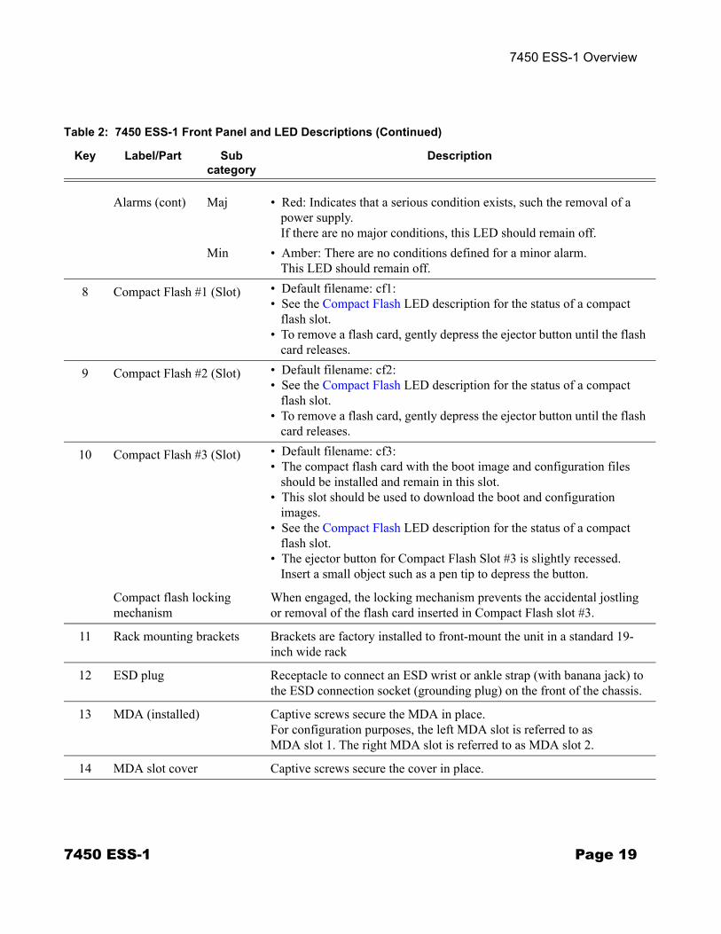
Table 2: 7450 ESS-1 Front Panel and LED Descriptions (Continued)
Key Label/Part Subcategory
Description
Page 18 7450 ESS-1
7450 ESS-1 Overview
Alarms (cont) Maj • Red: Indicates that a serious condition exists, such the removal of a power supply.If there are no major conditions, this LED should remain off.
Min • Amber: There are no conditions defined for a minor alarm.This LED should remain off.
8 Compact Flash #1 (Slot) • Default filename: cf1:• See the Compact Flash LED description for the status of a compact
flash slot.• To remove a flash card, gently depress the ejector button until the flash
card releases.
9 Compact Flash #2 (Slot) • Default filename: cf2:• See the Compact Flash LED description for the status of a compact
flash slot. • To remove a flash card, gently depress the ejector button until the flash
card releases.
10 Compact Flash #3 (Slot) • Default filename: cf3:• The compact flash card with the boot image and configuration files
should be installed and remain in this slot.• This slot should be used to download the boot and configuration
images.• See the Compact Flash LED description for the status of a compact
flash slot.• The ejector button for Compact Flash Slot #3 is slightly recessed.
Insert a small object such as a pen tip to depress the button.
Compact flash locking mechanism
When engaged, the locking mechanism prevents the accidental jostling or removal of the flash card inserted in Compact Flash slot #3.
11 Rack mounting brackets Brackets are factory installed to front-mount the unit in a standard 19-inch wide rack
12 ESD plug Receptacle to connect an ESD wrist or ankle strap (with banana jack) to the ESD connection socket (grounding plug) on the front of the chassis.
13 MDA (installed) Captive screws secure the MDA in place.For configuration purposes, the left MDA slot is referred to as MDA slot 1. The right MDA slot is referred to as MDA slot 2.
14 MDA slot cover Captive screws secure the cover in place.
Table 2: 7450 ESS-1 Front Panel and LED Descriptions (Continued)
Key Label/Part Subcategory
Description
7450 ESS-1 Page 19
Chassis Features
Back Panel Features
Figure 2 displays the 7450 ESS-1 AC/DC model back panel. Refer to Table 3 for key descriptions.
Figure 2: 7450 ESS-1 AC/DC Back Panel Features
1 2 3
4 55
6
SR01002
Table 3: 7450 ESS-1 AC/AC Back Panel Features
Key Description
1 Label
2 AC ON/OFF switch / AC power receptacle
3 DC -VDC plug
4 DC RTN plug
5 Grounding block
6 Mounting brackets
Page 20 7450 ESS-1
7450 ESS-1 Overview
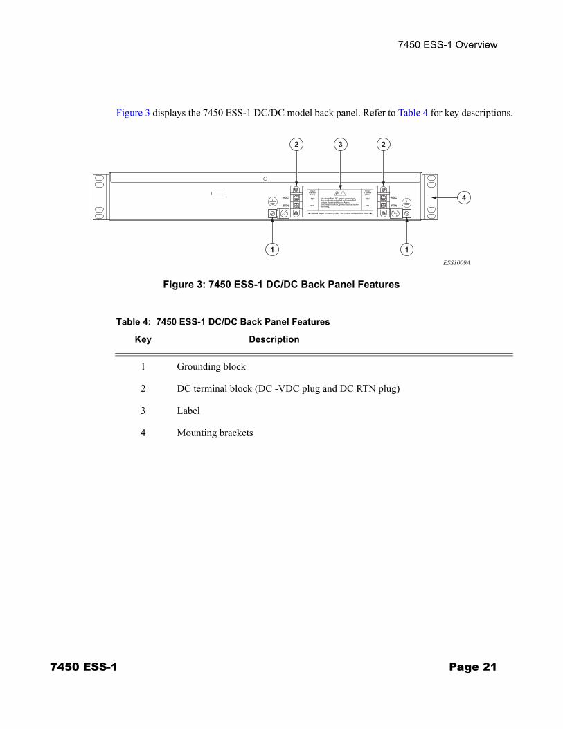
Figure 3 displays the 7450 ESS-1 DC/DC model back panel. Refer to Table 4 for key descriptions.
Figure 3: 7450 ESS-1 DC/DC Back Panel Features
3 22
11
4
ESS1009A
Table 4: 7450 ESS-1 DC/DC Back Panel Features
Key Description
1 Grounding block
2 DC terminal block (DC -VDC plug and DC RTN plug)
3 Label
4 Mounting brackets
7450 ESS-1 Page 21
Chassis Features
Component Operating Requirements
Table 5 displays the 7450 ESS-1 hardware component operating requirements. All components, except the cables and MDAs, are factory installed. Cables and MDAs are the only field replaceable parts in the chassis.
Table 5: 7450 ESS-1 Hardware Component Operating Requirements Summary
Component Minimum Maximum Field-Replaceable
Backplane 1 1 N
Power supplies:
AC/DC model 1 AC or1 DC
1 AC and1 DC
N
DC/DC model 1 2 DC N
Power cables:
AC/DC model 1 AC or1 DC
1 AC and1 DC
Y
DC/DC model 1 DC 2 DC Y
Fans 6 6 N
SF/CPM 1 1 N
IOM 1 1 N
MDAs (field replaceable) 1 2 Y
Page 22 7450 ESS-1
7450 ESS-1 Overview
ESS-1 System Installation Process
To install the 7450 ESS-1 system, perform the installation procedures in the following order:
Step 1 Prepare the site.
Step 2 Unpack the chassis, MDA(s), and AC cable.
Step 3 Mount the chassis.
Step 4 Prepare DC input power cable.
Step 5 Connect AC and/or DC input power cables.
Step 6 Power up the system.
Step 7 Preconfigure card slot, card-type, MDA, and ports.
Step 8 Install MDA(s).
Step 9 Connect network cables.
7450 ESS-1 Page 23

ESS-1 System Installation Process
Page 24 7450 ESS-1
Site Preparation
In This Chapter
This chapter provides information about preparing your site to install a 7450 ESS-1 router.
This chapter provides an overview of the following topics:
• Warnings and Notes on page 26• System Specifications on page 27
→ Chassis Specifications on page 27→ Environmental Specifications on page 27→ MDA Specifications on page 28→ Component Power Consumption on page 28→ Fans on page 35→ Storage on page 35
• Safety Considerations on page 31→ Power on page 32→ Grounding on page 31→ Fans on page 35→ Storage on page 35
• Safety Standards/Compliance Agency Certifications on page 36
7450 ESS-1 Page 25

Warnings and Notes
Warnings and Notes
Warning:
• Do not assume that power has been disconnected from a circuit. Be sure to disconnect power to the equipment rack and external cables before installing or removing the 7450 ESS-1 chassis.
• Do not install equipment that appears to be damaged.• 7450 ESS-1 systems equipped with DC-input power supplies should be installed in restricted
access areas, such as a dedicated equipment room or an equipment closet, in accordance with Articles 110-16, 110-17, and 110-18 of the National Electric Code ANSI/ NFPA 70.
Notes:
• Prepare the equipment rack and site before installing the chassis. Plan the placement near the power sources and network interface connections.
• An empty 7450 ESS-1 chassis weighs approximately 27 lbs. (12.25 kg).• For personal safety, use at least two people or a hand cart to install the chassis.• Always install the heaviest equipment on the bottom of the rack to keep the center of gravity of
the equipment rack as low as possible. • To provide necessary stability, ensure that the equipment rack is bolted to the floor. Ceiling
brackets are useful to provide additional stability. • The equipment rack must be properly grounded.• Install components after the chassis is installed in a rack.• Maintain a clearance of at least 20-inches (50.8 cm) at the front and back of the switch.• Maintain a clearance of at least 3-inches (7.6 cm) on each side to ensure adequate air intake and
exhaust.• The 7450 ESS-1 chassis includes factory installed rack mounting brackets to front mount in a
19-inch equipment rack.
Page 26 7450 ESS-1
Site Preparation
System Specifications
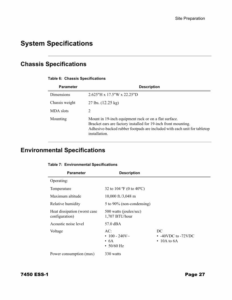
Chassis Specifications
Environmental Specifications
Table 6: Chassis Specifications
Parameter Description
Dimensions 2.625"H x 17.5"W x 22.25"D
Chassis weight 27 lbs. (12.25 kg)
MDA slots 2
Mounting Mount in 19-inch equipment rack or on a flat surface. Bracket ears are factory installed for 19-inch front mounting. Adhesive-backed rubber footpads are included with each unit for tabletop installation.
Table 7: Environmental Specifications
Parameter Description
Operating:
Temperature 32 to 104 ºF (0 to 40ºC)
Maximum altitude 10,000 ft./3,048 m
Relative humidity 5 to 90% (non-condensing)
Heat dissipation (worst case configuration)
500 watts (joules/sec)1,707 BTU/hour
Acoustic noise level 57.0 dBA
Voltage AC:• 100 - 240V~• 6A• 50/60 Hz
DC• -40VDC to -72VDC• 10A to 6A
Power consumption (max) 330 watts
7450 ESS-1 Page 27
System Specifications
MDA Specifications
Component Power Consumption
Table 8: MDA Specifications
Parameter Description
Dimensions 1.4" H x 7.5" W x 7" D
Weight 1.5 lb.
Table 9: Component Power Consumption
Component Maximum Power Consumption (Watts)
Chassis (low RPMs/no MDA) 179Chassis (high RPMs/no MDA) 200MDAs
10/100ETH-TX (60-port) 29100BASE-FX (20-port) 36GigE + 1-port 10GBASE (10-port) 551GB-SFP-B (5-port) 261GB-SFP (10-port) 261GB-SFP-B (10-port) 311GB-SFP (20-port) 58 1GB-TX (20-port) 6010GB-LW/LR (1-port) 27 10GB-EW/ER (1-port) 27 10GB-ZW/ZR (1-port) 28 10GB-XFP (1-port) 20 10GB-XFP (2-port) 40 OC-3-SFP (16-port) 48OC-12-SFP (8-port) 32OC-12-SFP (16-port) 50OC-48/STM-16 (2-port) 20OC-48/STM-16 (4-port) 24Versatile Service Module (VSM) (No ports)
10
Page 28 7450 ESS-1
Site Preparation
Installation Locations
The 7450 ESS-1 switch can be installed in either of the following:• An equipment rack.
Rack mounted units can be front or center mounted in many types of racks, including the following:→ Standard 19-inch (48.26 cm) equipment rack → Standard telco rack (four-post) Follow the equipment rack manufacturer’s instructions for proper rack installation. The equipment rack rail mounting holes must align with the mounting holes on the chassis mounting brackets. The 7450 ESS-1 mounting brackets are factory installed for a front mount in a 19-inch rack.Required tools: → #2 Phillips screwdriver → Flathead screwdriver→ Anti-static bags, mats, and packaging → ESD wrist strap
• A stable flat surface.Tabletop or shelves must be able to support the weight of the switch, or a stack of 7450 ESS-1 switches (up to 8 units high), and attached cables.Required tools: → Anti-static bags, mats, and packaging → ESD wrist strap
7450 ESS-1 Page 29
System Specifications
Chassis Clearance Requirements
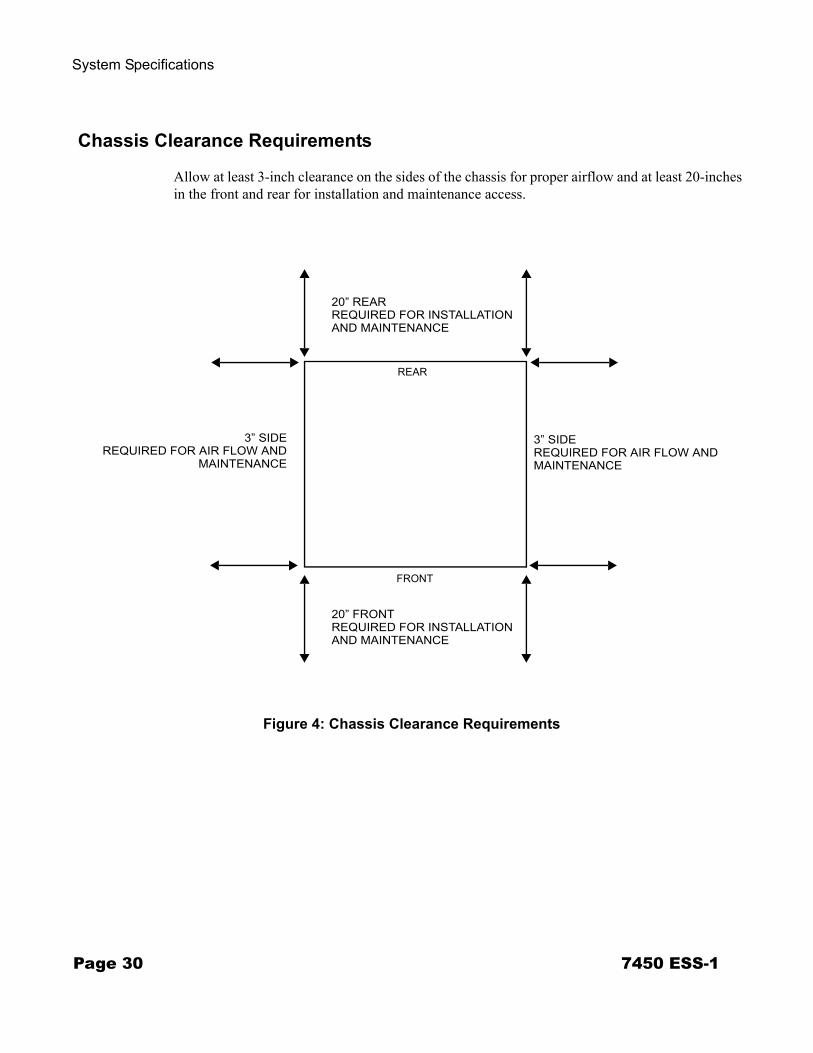
Allow at least 3-inch clearance on the sides of the chassis for proper airflow and at least 20-inches in the front and rear for installation and maintenance access.
Figure 4: Chassis Clearance Requirements
FRONT
REAR
20” REARREQUIRED FOR INSTALLATION
20” FRONTREQUIRED FOR INSTALLATION
3” SIDEREQUIRED FOR AIR FLOW AND
3” SIDEREQUIRED FOR AIR FLOW AND MAINTENANCEMAINTENANCE
AND MAINTENANCE
AND MAINTENANCE
Page 30 7450 ESS-1
Site Preparation
Safety Considerations
• Install the 7450 ESS-1 in standard sized equipment racks or a stable flat surface. • Install in clean, dry, ventilated, and temperature-controlled rooms.• Verify that the rack is properly bolted and braced and is properly grounded to a grounding
electrode.• Install the chassis into the equipment rack before installing components.• Table-stacked units must not be taller than 8 units high.
Grounding
The chassis and equipment rack must be properly grounded. Electrostatic discharge (ESD) damage can occur if components are mishandled. Always wear an ESD-preventive wrist or ankle strap and always connect an ESD strap (with banana plug) to the ESD connection socket (grounding jack) on the front of the chassis.
The ESS-1 includes an additional grounding jack on the rear panel of the chassis. If DC power is used, then the ground terminal must be connected. See DC-Input Power Supply Guidelines on page 55.
Warning: Use only power cords that have a grounding (earthing) path. Main grounding (earthing) connection points are through the IEC60320 appliance inlets. Grounding (earthing) points on the rear of the equipment are for equipotential bonding only and are not the safety grounding (earthing) points for the equipment. Lack of proper grounding (earthing) of the equipment may result in a safety hazard and excessive electromagnetic emissions. Refer to Table 11 on page 34 for descriptions of common grounding-type (earthing) power supply cords.If you ground the equipment by a method other than those provided in this manual, those means should be in compliance with all local wiring regulations and practices.
7450 ESS-1 Page 31
Safety Considerations
Power
• Only service electrical personnel should perform wiring and cabling to the system.• All power to the equipment rack or cabinet should be disconnected before the installation.• The power cable(s) must meet your local electric code requirements.• The circuit breaker is not intended to be used as the chassis ON/OFF switch. Unplug the
power cord from the power source and disconnect the cord from the receptacle on the power supply module to remove power.
Power Cord Requirements
The power cord set used with this 7450 ESS-1 must meet the local safety codes and requirements.
The requirements listed below are applicable to all countries:
• The length of the power cord must be at least 6 feet (1.8 m) and a maximum of 9.75 feet (3.0 m).
• All power cords must be approved by an acceptable accredited agency responsible for evaluation in the country where the power cord set is used.
• The power cord must have a minimum current capacity of 10A and a nominal voltage rating of 125V or 250V AC, as required by each country’s power system.
• The appliance coupler must meet the mechanical configuration of an EN 60 320/IEC 320 Standard Sheet C13 connector for mating with appliance inlet on the unit.
• The power cord set used with this 7450 ESS-1 must meet the local safety codes and requirements.
Page 32 7450 ESS-1
Site Preparation
Country-Specific Requirements
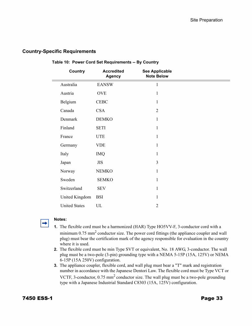
Table 10: Power Cord Set Requirements -- By Country
Country Accredited Agency
See Applicable Note Below
Australia EANSW 1
Austria OVE 1
Belgium CEBC 1
Canada CSA 2
Denmark DEMKO 1
Finland SETI 1
France UTE 1
Germany VDE 1
Italy IMQ 1
Japan JIS 3
Norway NEMKO 1
Sweden SEMKO 1
Switzerland SEV 1
United Kingdom BSI 1
United States UL 2
Notes:
1. The flexible cord must be a harmonized (HAR) Type HO5VV-F, 3-conductor cord with a minimum 0.75 mm2 conductor size. The power cord fittings (the appliance coupler and wall plug) must bear the certification mark of the agency responsible for evaluation in the country where it is used.
2. The flexible cord must be min Type SVT or equivalent, No. 18 AWG, 3-conductor. The wall plug must be a two-pole (3-pin) grounding type with a NEMA 5-15P (15A, 125V) or NEMA 6-15P (15A 250V) configuration.
3. The appliance coupler, flexible cord, and wall plug must bear a "T" mark and registration number in accordance with the Japanese Dentori Law. The flexible cord must be Type VCT or VCTF, 3-conductor, 0.75 mm2 conductor size. The wall plug must be a two-pole grounding type with a Japanese Industrial Standard C8303 (15A, 125V) configuration.
7450 ESS-1 Page 33
Safety Considerations
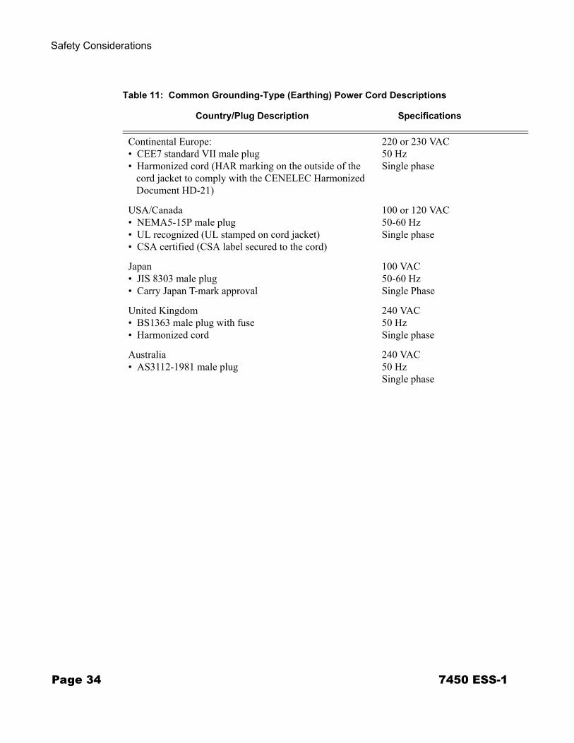
Table 11: Common Grounding-Type (Earthing) Power Cord Descriptions
Country/Plug Description Specifications
Continental Europe:• CEE7 standard VII male plug• Harmonized cord (HAR marking on the outside of the
cord jacket to comply with the CENELEC Harmonized Document HD-21)
220 or 230 VAC 50 HzSingle phase
USA/Canada• NEMA5-15P male plug• UL recognized (UL stamped on cord jacket)• CSA certified (CSA label secured to the cord)
100 or 120 VAC50-60 HzSingle phase
Japan • JIS 8303 male plug• Carry Japan T-mark approval
100 VAC50-60 HzSingle Phase
United Kingdom• BS1363 male plug with fuse• Harmonized cord
240 VAC50 HzSingle phase
Australia• AS3112-1981 male plug
240 VAC50 HzSingle phase
Page 34 7450 ESS-1
Site Preparation
Fans
There are six non-replaceable factory-installed fans.
The 7450 ESS-1 cooling system requires a minimum of 3-inches of unrestricted unobstructed air flow to function properly.
An MDA faceplate is required in an empty MDA slot to prevent excess dust accumulation and to help control airflow and electromagnetic interference.
Storage
To store uninstalled 7450 ESS-1 switches and extra field-replaceable parts (if applicable), re-wrap the components in the original packaging and keep them in a dry, dust-free temperature controlled environment.
Table 12: Storage Specifications
Parameter Description
Storage temperature From -40° to 158°F (-40° to 70°C)
Non-condensing relative humidity Within 5 to 95 percent.
7450 ESS-1 Page 35
Safety Standards/Compliance Agency Certifications
Safety Standards/Compliance Agency Certifications
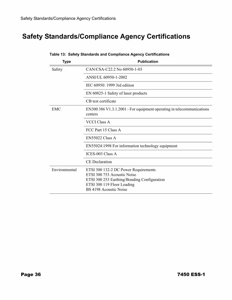
Table 13: Safety Standards and Compliance Agency Certifications
Type Publication
Safety CAN/CSA-C22.2 No 60950-1-03
ANSI/UL 60950-1-2002
IEC 60950: 1999 3rd edition
EN 60825-1 Safety of laser products
CB test certificate
EMC EN300 386 V1.3.1.2001 - For equipment operating in telecommunications centers
VCCI Class A
FCC Part 15 Class A
EN55022 Class A
EN55024:1998 For information technology equipment
ICES-003 Class A
CE Declaration
Environmental ETSI 300 132-2 DC Power RequirementsETSI 300 753 Acoustic NoiseETSI 300 253 Earthing/Bonding ConfigurationETSI 300 119 Floor LoadingBS 4198 Acoustic Noise
Page 36 7450 ESS-1

Installing the 7450 ESS-1
IN THIS CHAPTER
This chapter provides information about installing a 7450 ESS-1 switch.
This chapter provides information on the following topics:
• Unpacking the Chassis on page 38→ Unpacking Precautions on page 38
• Rack Mounting the Chassis on page 41• Table-Mounting the Chassis on page 43• Chassis Ground Wiring on page 46
→ Preparing the Ground Wire on page 46→ Making the Ground Connection on page 47
7450 ESS-1 Page 37
Unpacking the Chassis
Unpacking the Chassis
There are no field replaceable parts in the 7450 ESS-1 chassis. The IOM, power supply, and fans are integral to the chassis and are factory installed. AC and DC power cables and MDAs are the only field-installable and field-replaceable components.
Unpacking Precautions
Review this section to avoid injury or damage to the 7450 ESS-1:
• The shipping weight of the chassis is approximately 27 lbs. (12.25 kg). To prevent injury or damage to the router, two people should remove the router from the shipping crate and mount it into a rack.
• The chassis is shipped in a heavy corrugated cardboard container protected by a foam end caps. Do not discard the packaging container and materials used in shipping. The packing materials should be re-used if it is necessary to reship the router.
• Keep the chassis wrapped in the anti-static packaging until you are ready to install the router.
• Keep the arrows on the shipping container pointing up.
Page 38 7450 ESS-1
Installing the 7450 ESS-1
Figure 5: Unpacking the 7450 ESS-1 Chassis
1
8
7
65 4
6
2
3
SR10003A
Table 14: Unpacking the 7450 ESS-1 Chassis
Key Description
1 Label
2 Label
3 Shipping container
4/5 Accessory boxes
6 Foam end caps
7 Anti-static bag
8 7450 ESS-1 router
7450 ESS-1 Page 39
Unpacking the Chassis
Open the carton and follow these steps to unpack the chassis:
Step 1 Remove accessory kit.
Step 2 Lift contents to remove the foam end caps on the sides of the router.
Step 3 The chassis shipping weight is approximately 27 lbs. (12.25 kg). Carefully remove the router from the box.
Step 4 Remove the protective anti-static wrapping.
Caution: There are no handles or hand grips on the 7450 ESS-1. Lift the chassis by the bottom of the chassis. Do not put your hands inside an MDA slot to lift.
Page 40 7450 ESS-1
Installing the 7450 ESS-1
Rack Mounting the Chassis
The 7450 ESS-1 router chassis is designed for front and middle-mount installation into a 19-inch rack. The rack mounting hardware (including rack bolts) is factory installed to front-mount the chassis in a 19-inch rack.
It is easier to install the ESS-1 chassis in the rack with two people, one person to hold the router and one person to secure it into the rack.
Required tools:
• Use a screwdriver to loosen and tighten the mounting bracket bolts.
Before you begin, verify:
• The equipment rack is securely installed, anchored, and grounded. Refer to the rack manufacturer’s documentation for instructions.
• The power to the rack is OFF.
Danger:
• Only trained and qualified personnel should install or replace this equipment.
Caution: • There are no handles or hand grips on the 7450 ESS-1. Lift the router from underneath. Do
not lift the router by the MDA slots.• When rack mounting the chassis in an equipment rack, do not stack other ESS-1 units or
any other equipment directly on top (where the bottom unit is supporting other devices). Each unit must be secured into the rack with the appropriate mounting apparatus.
7450 ESS-1 Page 41
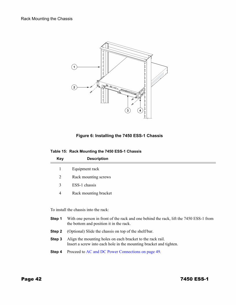
Rack Mounting the Chassis
Figure 6: Installing the 7450 ESS-1 Chassis
To install the chassis into the rack:
Step 1 With one person in front of the rack and one behind the rack, lift the 7450 ESS-1 from the bottom and position it in the rack.
Step 2 (Optional) Slide the chassis on top of the shelf/bar.
Step 3 Align the mounting holes on each bracket to the rack rail. Insert a screw into each hole in the mounting bracket and tighten.
Step 4 Proceed to AC and DC Power Connections on page 49.
43
2
1
SR10005
Table 15: Rack Mounting the 7450 ESS-1 Chassis
Key Description
1 Equipment rack
2 Rack mounting screws
3 ESS-1 chassis
4 Rack mounting bracket
Page 42 7450 ESS-1
Installing the 7450 ESS-1
Table-Mounting the Chassis
The 7450 ESS-1 chassis can be installed on a flat surface, such as a tabletop or shelf. Rubber footpads are included in with each accessory kit. It is optional to remove the factory installed rack mounting brackets.
Before you begin, verify:
• The surface is sturdy and can support the weight of the router, or a stack of routers (up to 8 units high) and attached cables.
• Ventilation and maintenance requirements are met.
Figure 7 displays the locations to attach the footpads on the bottom side of the chassis.
Danger:
• Only trained and qualified personnel should install or replace this equipment.
Caution: • There are no handles or hand grips on the 7450 ESS-1. Lift the router from underneath. Do
not lift the router by the MDA slots.• The router should be installed on an elevated flat surface, off the floor. • 7450 ESS-1 routers must not be stacked taller than 8 units high. • The ventilation and maintenance clearance dimensions are the same for table-mounted units
as for rack-mounted units. See Chassis Clearance Requirements on page 30.
7450 ESS-1 Page 43
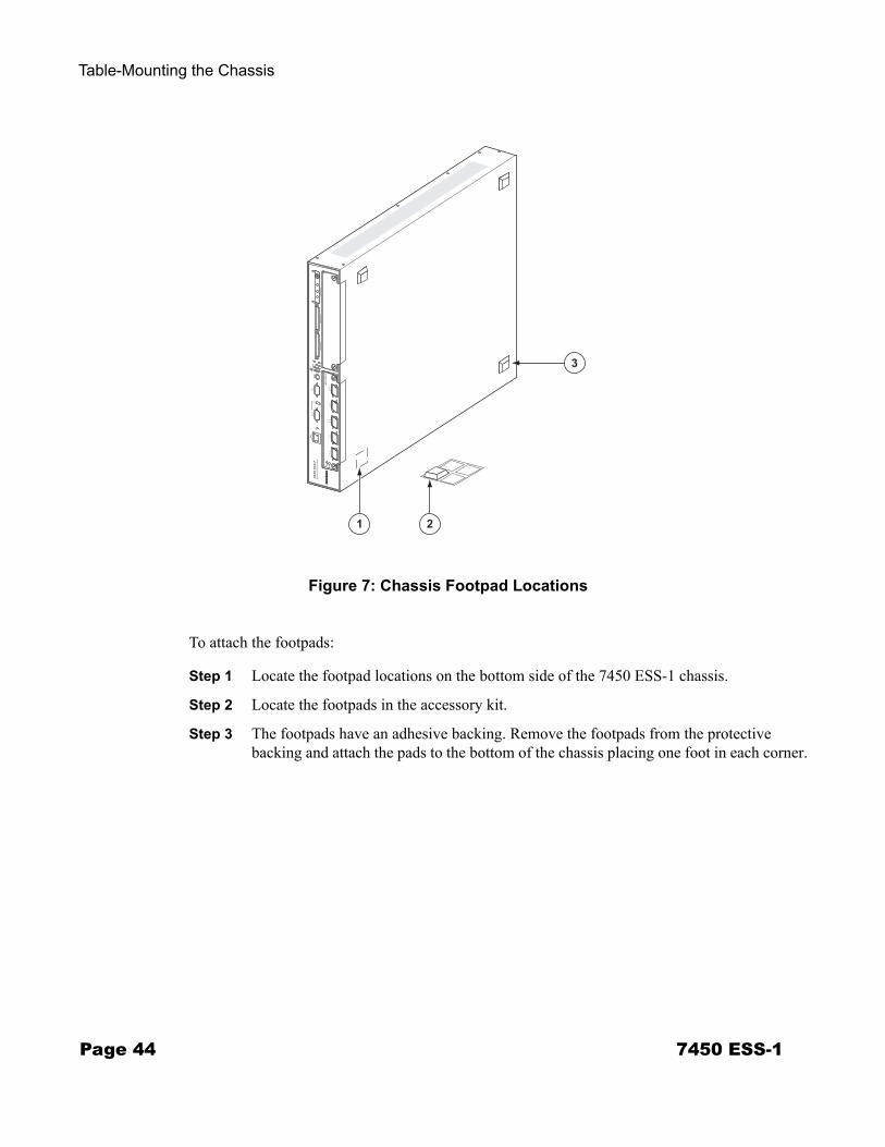
Table-Mounting the Chassis
Figure 7: Chassis Footpad Locations
To attach the footpads:
Step 1 Locate the footpad locations on the bottom side of the 7450 ESS-1 chassis.
Step 2 Locate the footpads in the accessory kit.
Step 3 The footpads have an adhesive backing. Remove the footpads from the protective backing and attach the pads to the bottom of the chassis placing one foot in each corner.
ESS1003
Reset
3
1 2
Page 44 7450 ESS-1
Installing the 7450 ESS-1
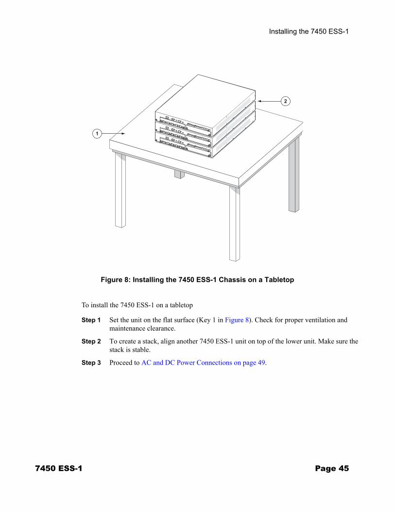
Figure 8: Installing the 7450 ESS-1 Chassis on a Tabletop
To install the 7450 ESS-1 on a tabletop
Step 1 Set the unit on the flat surface (Key 1 in Figure 8). Check for proper ventilation and maintenance clearance.
Step 2 To create a stack, align another 7450 ESS-1 unit on top of the lower unit. Make sure the stack is stable.
Step 3 Proceed to AC and DC Power Connections on page 49.
SR10031
2
1
7450 ESS-1 Page 45
Chassis Ground Wiring
Chassis Ground Wiring
To make sure that the equipment is connected to earth ground, follow the instructions to prepare the ground wire. Grounding cables are not provided. The length of the grounding wire depends on the location of the chassis and proximity to the proper grounding facilities.
Preparing the Ground Wire
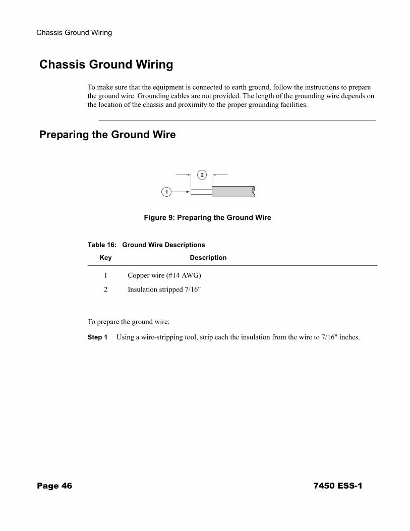
Figure 9: Preparing the Ground Wire
To prepare the ground wire:
Step 1 Using a wire-stripping tool, strip each the insulation from the wire to 7/16" inches.
1
2
SR10030
Table 16: Ground Wire Descriptions
Key Description
1 Copper wire (#14 AWG)
2 Insulation stripped 7/16"
Page 46 7450 ESS-1
Installing the 7450 ESS-1
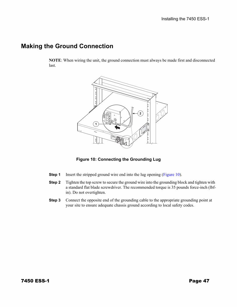
Making the Ground Connection
NOTE: When wiring the unit, the ground connection must always be made first and disconnected last.
Figure 10: Connecting the Grounding Lug
Step 1 Insert the stripped ground wire end into the lug opening (Figure 10).
Step 2 Tighten the top screw to secure the ground wire into the grounding block and tighten with a standard flat blade screwdriver. The recommended torque is 35 pounds force-inch (lbf-in). Do not overtighten.
Step 3 Connect the opposite end of the grounding cable to the appropriate grounding point at your site to ensure adequate chassis ground according to local safety codes.
1
2
SR10028
7450 ESS-1 Page 47

Chassis Ground Wiring
Page 48 7450 ESS-1
AC and DC Power Connections
IN THIS CHAPTER
This chapter provides information about AC and DC wiring and connections.
This chapter provides information on the following topics:
• Wiring and Connecting AC and DC Power on page 50→ Warnings and Notes on page 50
• AC-Input Power Supply Guidelines on page 52→ Connecting AC Power on page 53
• DC-Input Power Supply Guidelines on page 55→ Wiring for DC-Input Power on page 56→ DC Input Terminal Block Wiring on page 56
• Powering Up the Switch on page 59
7450 ESS-1 Page 49
Wiring and Connecting AC and DC Power
Wiring and Connecting AC and DC Power
Warnings and Notes
Danger: • Make your ground connections first. • Only a qualified personnel should install or replace this equipment. • Confirm that the DC power source is OFF during installation. The power source should be a
safety extra-low voltage (SELV) source.• Turn off power at the power source before you install or remove power cords. • Before working on equipment that is connected to power, remove jewelry, such as rings,
necklaces, and watches. When metal objects are in contact with power and ground, serious burns can occur or the objects can be welded to the terminals.
• You must use cables which meet local electrical code requirements. • AC power cord set supplied with this product is strictly restricted for use with this product only.
The AC power cord set must not be used for any other purposes or any other products. When applying power to the chassis, be sure to use the supplied AC power cord set, and make sure that you do not use any other product's AC power cord set.Japanese note:
• The unit should be connected to a DC branch circuit with a maximum 20A circuit breaker or fuse which meets the requirements for branch circuit protection. A suitable disconnect device must be provided in the DC branch, either a circuit breaker or switch that can be employed to disconnect power to the system during servicing.
Caution:
• This product relies on the building’s installation for short-circuit (over current) protection. Ensure that a circuit breaker, or other equivalent means, rated 20A, is used in the building’s AC branch circuit for the current carrying conductors.
Page 50 7450 ESS-1
AC and DC Power Connections
Warning: • Do not install equipment that appears to be damaged.• The chassis and equipment rack must be properly grounded. Electrostatic discharge (ESD)
damage can occur if components are mishandled. Always wear an ESD-preventive wrist or ankle strap and always connect an ESD strap (with banana jack) to the ESD connection socket (grounding plug) on the front of the chassis.
• If your disconnect device is not permanently incorporated, a readily accessible disconnect device to shut off power during servicing must be incorporated in your building’s branch circuit.
Notes: • The 7450 ESS-1 requires a minimum of one power connection to operate, but using both
connections in the AC/DC or dual DC models are recommended for redundancy.• A 20A (max.) circuit breaker is recommended for AC power.• In the event of a power supply failure, the entire 7450 ESS-1 chassis must be repaired or
replaced. There are no field serviceable parts.• The equipment under test (EUT) is specified for DC-I power configurations. The battery returns
must remain isolated until they reach the main power buss.• All bare conductors must be coated with an appropriate antioxidant compound before crimp
connections are made. All unplated connectors, braided strap, and bus bars are to be brought to a bright finish and then coated with an antioxidant before connecting them.
• All surfaces that are used for intentionally grounding the EUT shall be brought to a bright finish and an anti oxidant solution must be applied to the surfaces being joined.
• Non-conductive coatings (such as lacquer and enamel) must be removed from threads and other contact surfaces to assure electrical conductivity. (Thread forming screws with paint piercing washers may be used for this purpose during installation)
• To comply with the GR-1089-CORE, Issue 03, requirement R4-9 [31] standard for electromagnetic compatibility and safety, all intra-building ports are specified for use with shielded and grounded cables at both ends.
• The intra-building port(s) of the equipment or sub-assembly is suitable for connection to intra-building or unexposed wiring or cabling only. The intra-building port(s) of the equipment or subassembly must not be metallically connected to interfaces that connect to the Outside Plant (OSP) or its wiring. These interfaces are designed for use as intra-building interfaces only (Type 2 or Type 4 ports as described in GR-1089-CORE, Issue 4) and require isolation from the exposed OSP cabling. The addition of primary protectors is not sufficient protection in order to connect these interfaces metallically to OSP wiring.
7450 ESS-1 Page 51
AC-Input Power Supply Guidelines
AC-Input Power Supply Guidelines
If you intend to use AC-input power in the 7450 ESS-1, observe the following:
• There is one AC power cord receptacle located at the rear of the 7450 ESS-1AC/DC model chassis.
• The power supply operates with a nominal utility system voltage of 100V to 240V, but will operate with input voltages ranging from 85 to 264 VAC.
• A fully redundant system operates with two power systems. AC and DC power types are available in the 7450 ESS-1 chassis.→ AC/DC model — Plug an AC power cord into the AC receptacle at the rear of the
chassis. Wire the single DC terminal block on the AC/DC model. → DC/DC model — Wire both DC terminal blocks on the DC/DC model.
• An AC power cord is shipped with each 7450 ESS-1 AC/DC model unit.
The chassis has a AC plug receptacle to accept an AC power cord. The other end of the AC power cord must have a plug that fits into the power source receptacle that is standard for your geographic region.
Page 52 7450 ESS-1
AC and DC Power Connections
7450 ESS-1 Page 53
Connecting AC Power
Figure 11: Connecting AC Power
1
2
3
SR10012
Table 17: AC Power Field Descriptions
Key Description
1 Power cord
2 Power cord retainer
3 Remote power source (example)
AC-Input Power Supply Guidelines
Page 54 7450 ESS-1
To connect the AC power:
Step 1 Locate the AC power cord that was shipped with the AC/DC unit. Verify that the cord meets your regional requirements. Do not use power cords that do not meet these standards.
Step 2 Plug the AC power cord into the receptacle at the rear of the chassis.
Step 3 Engage the power cord retainer by lowering the retainer bracket toward from the power cord and snap the bracket in place.
Step 4 Plug the other end of the power cord into a 3-terminal, single-phase power source that provides power within the acceptable range (100-240 VAC, 50/60 Hz, 12.0 ~ 6.0 A).
Step 5 Turn the power switch on the rear panel to the ON position.
Step 6 Check the front panel Status and Power Supply # 1 LED.
AC and DC Power Connections
DC-Input Power Supply Guidelines
If you intend to use DC-input power in the 7450 ESS-1, observe the following:
• A fully redundant system operates with two power systems. AC and DC power types are available in the 7450 ESS-1 chassis.→ DC/DC model — Wire both DC terminal blocks on the DC/DC model. → AC/DC model — Plug an AC power cord into the AC receptacle at the rear of the
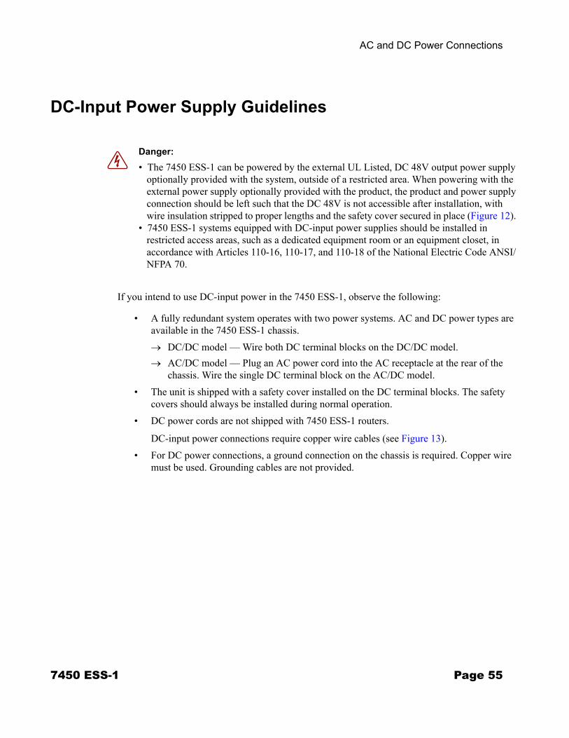
chassis. Wire the single DC terminal block on the AC/DC model. • The unit is shipped with a safety cover installed on the DC terminal blocks. The safety
covers should always be installed during normal operation. • DC power cords are not shipped with 7450 ESS-1 routers.
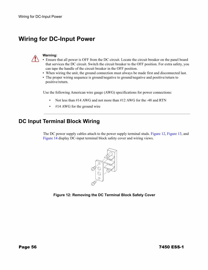
DC-input power connections require copper wire cables (see Figure 13).• For DC power connections, a ground connection on the chassis is required. Copper wire
must be used. Grounding cables are not provided.
Danger: • The 7450 ESS-1 can be powered by the external UL Listed, DC 48V output power supply
optionally provided with the system, outside of a restricted area. When powering with the external power supply optionally provided with the product, the product and power supply connection should be left such that the DC 48V is not accessible after installation, with wire insulation stripped to proper lengths and the safety cover secured in place (Figure 12).
• 7450 ESS-1 systems equipped with DC-input power supplies should be installed in restricted access areas, such as a dedicated equipment room or an equipment closet, in accordance with Articles 110-16, 110-17, and 110-18 of the National Electric Code ANSI/ NFPA 70.
7450 ESS-1 Page 55
Wiring for DC-Input Power
Wiring for DC-Input Power
Use the following American wire gauge (AWG) specifications for power connections:
• Not less than #14 AWG and not more than #12 AWG for the -48 and RTN• #14 AWG for the ground wire
DC Input Terminal Block Wiring
The DC power supply cables attach to the power supply terminal studs. Figure 12, Figure 13, and Figure 14 display DC-input terminal block safety cover and wiring views.
Figure 12: Removing the DC Terminal Block Safety Cover
Warning: • Ensure that all power is OFF from the DC circuit. Locate the circuit breaker on the panel board
that services the DC circuit. Switch the circuit breaker to the OFF position. For extra safety, you can tape the handle of the circuit breaker in the OFF position.
• When wiring the unit, the ground connection must always be made first and disconnected last. • The proper wiring sequence is ground/negative to ground/negative and positive/return to
positive/return.
SR10029
Page 56 7450 ESS-1
AC and DC Power Connections
Figure 13: Wiring the DC-Input Power Terminal Block
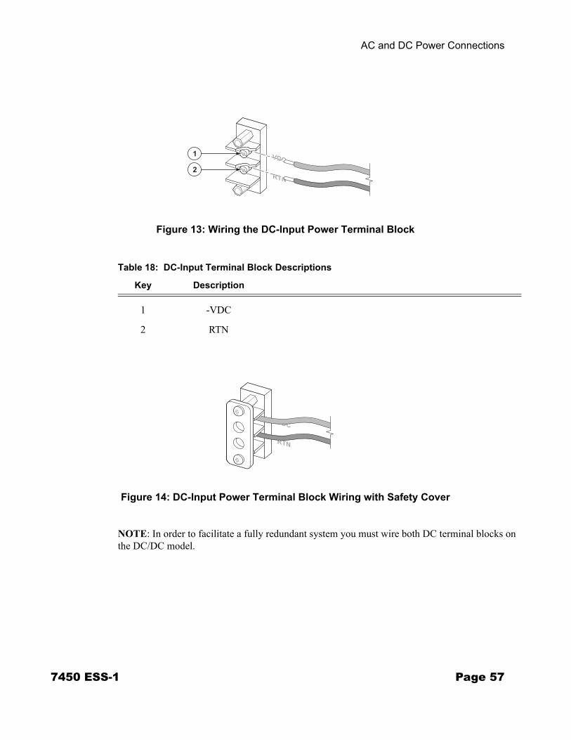
Figure 14: DC-Input Power Terminal Block Wiring with Safety Cover
NOTE: In order to facilitate a fully redundant system you must wire both DC terminal blocks on the DC/DC model.
1
2
SR10010
Table 18: DC-Input Terminal Block Descriptions
Key Description
1 -VDC
2 RTN
SR10033
7450 ESS-1 Page 57
Wiring for DC-Input Power
Follow these steps to wire a DC-input power terminal block(s):
Step 1 Prepare the DC cables. Strip the wire insulation to the length according to your local safety codes.
Step 2 Remove the safety cover from the DC terminal block.
Step 3 Loosen the -VDC and RTN terminal screws.
Step 4 Connect the RTN positive/return (+) cable to the bottom (RTN) terminal according to local safety codes.
Step 5 Tighten with a torque screwdriver or a ratcheting torque screwdriver with a Phillips or flat head. The recommended torque is 9 pounds force-inch (lbf-in).
Step 6 Connect the VDC (-) cable to the top (-48V) terminal according to local safety codes.
Step 7 Tighten with a torque screwdriver with a Phillips or flat head. The recommended torque is 9 pounds force-inch (lbf-in).
Step 8 If the safety cover was removed in Step 2, then replace the safety cover.
Page 58 7450 ESS-1
AC and DC Power Connections
Powering Up the Switch
To power up the ESS-1 follow these steps:
If you use the AC-power system:
Step 1 Turn ON the system power switch. The Status LED on the front panel should be lit green.
Step 2 Check the #1 Power Supply LED on the 7450 ESS-1 front panel. It should be lit green.
If you use the DC-powered system:
Step 1 Turn on the power at the remote power source(s).
Step 2 Check the #2 Power Supply LED on the 7450 ESS-1 front panel. It should be lit green.
7450 ESS-1 Page 59

Powering Up the Switch
Page 60 7450 ESS-1
Connections and Configurations
IN THIS CHAPTER
This chapter provides information about configuring and installing MDAs and ports.
This chapter provides information on the following topics:
• Initializing the System on page 62→ Using the Compact Flash Slot #3 Locking Mechanism on page 63→ Initial System Startup on page 64→ Troubleshooting on page 64
• Establishing Connections on page 67→ Console Connection on page 67→ Telnet Connection on page 69
• Configuring Slot, IOM, and MDA Parameters on page 72→ Card and Card-Type Commands on page 72→ MDA and MDA-Type Commands on page 73
• Specifying the Power Type on page 75• Installing MDAs on page 76
→ Installing an MDA on page 77→ Removing an MDA on page 79→ Replacing an MDA on page 80
7450 ESS-1 Page 61
Initializing the System
Initializing the System
The primary copy of 7450 ESS OS software is located on a compact flash card. The removable media shipped with each software license and contains a copy of the 7450 ESS OS software.
Notes: • The SF/CPM modules contain three slots for removable compact flash cards. The drives are
named Compact Flash Slot #1 (cf1), Compact Flash Slot #2 (cf2), and Compact Flash Slot #3 (cf3). Configurations and executable images can be stored on flash cards or an FTP file location.
• The flash card containing the bootstrap and boot option files must be installed in Compact Flash Slot #3 (cf3) on the front panel.
• You must have a console connection. See Console Connection on page 67.
Page 62 7450 ESS-1
Connections and Configurations
Using the Compact Flash Slot #3 Locking Mechanism
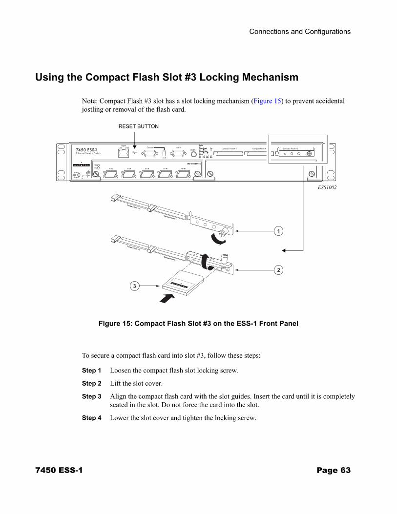
Note: Compact Flash #3 slot has a slot locking mechanism (Figure 15) to prevent accidental jostling or removal of the flash card.
Figure 15: Compact Flash Slot #3 on the ESS-1 Front Panel
To secure a compact flash card into slot #3, follow these steps:
Step 1 Loosen the compact flash slot locking screw.
Step 2 Lift the slot cover.
Step 3 Align the compact flash card with the slot guides. Insert the card until it is completely seated in the slot. Do not force the card into the slot.
Step 4 Lower the slot cover and tighten the locking screw.
ESS1002
3
1
2
SR10026A
RESET BUTTON
7450 ESS-1 Page 63

Initial System Startup
Initial System Startup
To initialize the system, follow these steps:
Step 1 When the compact flash card is installed in the slot, the Compact Flash 3 LED (located on the front panel) should light green within approximately 30 seconds. If it does not light or if it turns off again, refer to Troubleshooting.
Step 2 Depress the Reset button or power cycle the switch to initiate the boot process.
Step 3 The system searches Compact Flash Slot #3 (cf3) for the boot.ldr file (also known as the bootstrap file).
Step 4 Verify the operational status by checking the Power and Status LEDs on the SF/CPM faceplate. If the LEDs on the front panel blink continuously, refer to Troubleshooting.
Step 5 After verifying the LEDs, proceed with the MDA installation and configurations.
Troubleshooting
If the system cannot load or cannot find the boot.ldr file on cf3, the system checks for a manual boot sequence interruption. Unless an unsuccessful system initialization is manually interrupted, the system will continuously reboot in an attempt to successfully find and load the boot.ldr file.
When the system finds the boot.ldr file, the system processes the initialization parameters from the BOF. The BOF should be on the same drive as the boot loader file. If the BOF cannot be found or loaded, then the system prompts for a different image and configuration location.
When the image is successfully loaded, control is passed from the boot loader file to the image. The runtime image attempts to locate the configuration file as configured in the BOF. The configuration file include chassis, IOM, MDA, and port configurations, as well as system, routing, and service configurations.
Page 64 7450 ESS-1
Connections and Configurations
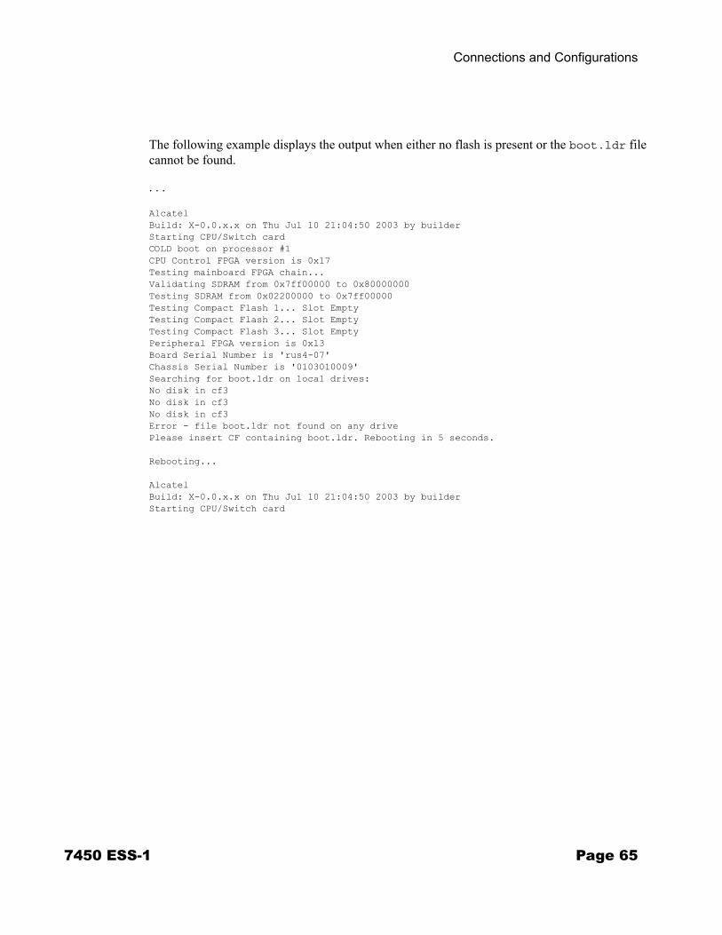
The following example displays the output when either no flash is present or the boot.ldr file cannot be found.
. . .
AlcatelBuild: X-0.0.x.x on Thu Jul 10 21:04:50 2003 by builderStarting CPU/Switch cardCOLD boot on processor #1CPU Control FPGA version is 0x17Testing mainboard FPGA chain...Validating SDRAM from 0x7ff00000 to 0x80000000Testing SDRAM from 0x02200000 to 0x7ff00000Testing Compact Flash 1... Slot EmptyTesting Compact Flash 2... Slot EmptyTesting Compact Flash 3... Slot EmptyPeripheral FPGA version is 0x13Board Serial Number is 'rus4-07'Chassis Serial Number is '0103010009'Searching for boot.ldr on local drives:No disk in cf3No disk in cf3No disk in cf3Error - file boot.ldr not found on any drivePlease insert CF containing boot.ldr. Rebooting in 5 seconds.
Rebooting...
AlcatelBuild: X-0.0.x.x on Thu Jul 10 21:04:50 2003 by builderStarting CPU/Switch card
7450 ESS-1 Page 65

Initial System Startup
Figure 16 displays the compact flash directory structure and file names.
Figure 16: Files on the Compact Flash
Files on the compact flash are:
• bof.cfg — Boot option file• boot.ldr — Bootstrap image• config.cfg — Default configuration file• TIMOS-m.n.Yz:
m — Major release number
n — minor release number
Y: A — Alpha release
B — Beta release
M — Maintenance release
R — Released software
z — Version number→ both.tim — CPM and IOM image file
ROOT
bof.cfg boot.ldr config.cfg TIMOS-n.m.Yz
both.tim
Page 66 7450 ESS-1
Connections and Configurations
Establishing Connections
Access the newly installed 7450 ESS two ways:
• Console Connection on page 67• Telnet Connection on page 69
Console Connection
To establish a console connection, you will need the following:
• An ASCII terminal or a PC running terminal emulation software set to the parameters shown in the table below.
• A standard serial cable with a female DB9 connector.
For pinout information, refer to Appendix B: Pinout Assignments on page 87.
Table 19: Console Configuration Parameter Values
Parameter Value
Baud Rate 115,200
Data Bits 8
Parity None
Stop Bits 1
Flow Control None
7450 ESS-1 Page 67
Establishing Connections
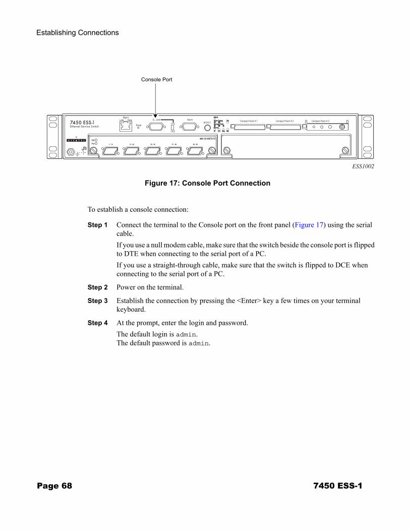
Figure 17: Console Port Connection
To establish a console connection:
Step 1 Connect the terminal to the Console port on the front panel (Figure 17) using the serial cable.If you use a null modem cable, make sure that the switch beside the console port is flipped to DTE when connecting to the serial port of a PC.If you use a straight-through cable, make sure that the switch is flipped to DCE when connecting to the serial port of a PC.
Step 2 Power on the terminal.
Step 3 Establish the connection by pressing the <Enter> key a few times on your terminal keyboard.
Step 4 At the prompt, enter the login and password.The default login is admin.The default password is admin.
ESS1002
Console Port
Page 68 7450 ESS-1
Connections and Configurations
Telnet Connection
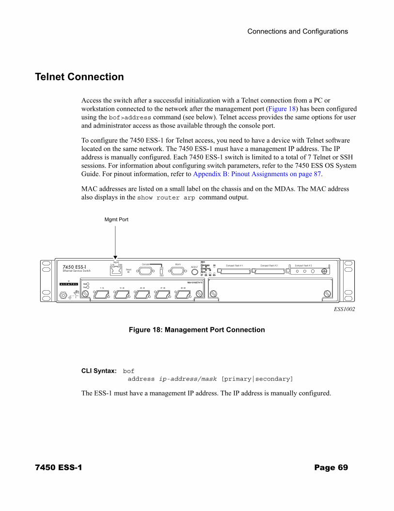
Access the switch after a successful initialization with a Telnet connection from a PC or workstation connected to the network after the management port (Figure 18) has been configured using the bof>address command (see below). Telnet access provides the same options for user and administrator access as those available through the console port.
To configure the 7450 ESS-1 for Telnet access, you need to have a device with Telnet software located on the same network. The 7450 ESS-1 must have a management IP address. The IP address is manually configured. Each 7450 ESS-1 switch is limited to a total of 7 Telnet or SSH sessions. For information about configuring switch parameters, refer to the 7450 ESS OS System Guide. For pinout information, refer to Appendix B: Pinout Assignments on page 87.
MAC addresses are listed on a small label on the chassis and on the MDAs. The MAC address also displays in the show router arp command output.
Figure 18: Management Port Connection
CLI Syntax: bofaddress ip-address/mask [primary|secondary]
The ESS-1 must have a management IP address. The IP address is manually configured.
ESS1002
Mgmt Port
7450 ESS-1 Page 69

Establishing Connections
Running Telnet
Once the IP parameters are configured, the CLI command line can be accessed with a Telnet connection. To establish a Telnet connection, run a Telnet program and issue the Telnet command, followed by the IP address:
The following displays an example of a Telnet login:
C:\>telnet 192.168.1.111Login: adminPassword: ########
ALA-1#
Page 70 7450 ESS-1
Connections and Configurations
Ejecting Flash Cards
To eject the slot #3 flash card:
Step 1 The shutdown command MUST be issued prior to removing a flash card. Command Examplefile shutdown cflash-id ALA-1# file shutdown cf3:
Step 2 Loosen the compact flash slot locking screw.
Step 3 Lift the slot cover.
Step 4 The ejector button for Compact Flash Slot #3 is slightly recessed. Insert a small object such as a pen tip to depress the button. The card will partially pop out of the slot.
Step 5 Remove the card and place it in an anti-static bag. The flash card containing the boot and configuration files must be installed in Compact Flash Slot #3 (cf3:) on the SF/CPM card.
Step 6 Lower the slot cover and tighten the locking screw.
To eject the slot #1 or slot #2 flash cards:
Step 1 The shutdown command MUST be issued to prior to removing a flash card. Command Examplefile>shutdown cflash-id ALA-1# file shutdown cf1:
file>shutdown cflash-id ALA-1# file shutdown cf2:
Step 2 Press the ejector button on compact flash slot #1 or compact flash slot #2. The card will partially pop out of the slot.
Step 3 Remove the card and place it in an anti-static bag.
7450 ESS-1 Page 71
Configuring Slot, IOM, and MDA Parameters
Configuring Slot, IOM, and MDA Parameters
After the 7450 ESS-1 is initialized, the MDA and port parameters can be configured. Even though the IOM is an integral part of the unit, the slot and card type must be manually specified. The MDA slot and MDA type must be configured in order to configure ports. Ports cannot be configured until the MDA is configured.
Configure components in the following order:
1. Card slot number
2. Card type
3. MDA slot number
4. MDA type
5. Ports
Card and Card-Type Commands
NOTE: When configuring the chassis slot (Step 1), the slot number value is always 1 for ESS-1 models.
In the config>card context, use the following CLI commands and syntax examples to provision the chassis slot and IOM:
Command ExampleStep 1 card slot-number card 1
Step 2 card-type card-type card-type iom-20g
Step 3 no shutdown no shutdown
Page 72 7450 ESS-1
Connections and Configurations
MDA and MDA-Type Commands
For configuration purposes, the left MDA slot is referred to as MDA slot 1. The right MDA slot is referred to as MDA slot 2. MDA information must be must be configured before ports can be configured.
After the IOM is configured, use the following CLI commands to provision the MDA(s). A maximum of two MDAs can be configured on an IOM.
Command Example
Step 1 mda mda-number mda 1
Step 2 mda-type mda-type mda-type ess-m10-1gb-sfp
Step 3 no shutdown no shutdown
Step 4 exit exit
To provision an additional MDA, continue the configuration process with Step 5:
Step 5 mda mda-number mda 2
Step 6 mda-type mda-type mda-type ess-m20-100eth-sfp
Step 7 no shutdown no shutdown
Step 8 exit exit
Example
The following example displays card slot, card type, MDA slot, and MDA type command usage:
ALA-1>config# card 1ALA-1>config>card# card-type iom-20gALA-1>config>card# mda 1ALA-1>config>card>mda# mda-type ess-m10-1gb-sfpALA-1>config>card>mda# no shutdownALA-1>config>card>mda# exitALA-1>config>card# mda 2ALA-1>config>card>mda# mda-type ess-m20-100eth-sfpALA-1>config>card>mda# no shutdownALA-1>config>card>mda# exit
7450 ESS-1 Page 73
Configuring Slot, IOM, and MDA Parameters
The following example displays the configuration:
ALA-1>config# info. . . ----------------------------------------------echo "Card Configuration "#------------------------------------------
card 1 card-type iom-20g mda 1 mda-type ess-m10-1gb-sfp exit mda 2 mda-type ess-m20-100eth-sfp exit
exit----------------------------------------------ALA-1>config#
To configure ports, refer to the Card and Port Configuration section of the 7450 ESS OS System Guide.
Page 74 7450 ESS-1
Connections and Configurations
Specifying the Power Type
If you connect DC power in either the DC/DC or AC/DC models, you must change the default for the power supply configuration to reflect the DC unit(s) in the CLI in order to facilitate proper operation for the LEDs, show command, and logging output.Refer to the 7450 ESS OS System Guide for command syntax and usage information.
CLI Syntax: config>systempower-supply {1|2} {dc|ac {single|multiple}|none}
Example: ALA-1>config>system# power-supply 1 dc ALA-1>config>system# power-supply 2 dc
The following example displays the power-supply command configuration:
ALA-1>config>system# info-----------------------------------------------------------------.. name "ALA-1" contact "Fred Information Technology" location "Bldg.1-floor 2-Room 201" clli-code "abcdefg1234" coordinates "N 45 58 23, W 34 56 12" power-supply 1 dc power-supply 2 dc exit..-----------------------------------------------------------------ALA-1>config>system#
7450 ESS-1 Page 75

Installing MDAs
Installing MDAs
Warnings and Notes
Danger: • Only trained and qualified personnel should install or replace this equipment.• Use of controls or adjustments of performance or procedures other than those specified herein
can result in hazardous radiation exposure.
Warning: • Electrostatic discharge (ESD) damage can occur if MDAs are mishandled. Always wear an
ESD-preventive wrist or ankle strap and always connect an ESD strap to the grounding plug on the front of the chassis.
• Invisible laser radiation can be emitted from the aperture ports of an MDA when no cable is connected. Avoid exposure and do not stare into open apertures.
• Always place components on an anti-static surface. • Do not power up a 7450 ESS-1 switch until all components are installed and verified. • Use only approved small form factor pluggable fiber optic devices in MDA ports.
Notes: General:• Ports cannot be provisioned until the MDA is provisioned.• Services cannot be provisioned until the ports are configured.
Page 76 7450 ESS-1
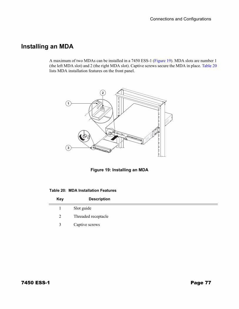
Connections and Configurations
Installing an MDA
A maximum of two MDAs can be installed in a 7450 ESS-1 (Figure 19). MDA slots are number 1 (the left MDA slot) and 2 (the right MDA slot). Captive screws secure the MDA in place. Table 20 lists MDA installation features on the front panel.
Figure 19: Installing an MDA
2
1
3
SR10008
Table 20: MDA Installation Features
Key Description
1 Slot guide
2 Threaded receptacle
3 Captive screws
7450 ESS-1 Page 77
Installing MDAs
To install an MDA:
Step 1 Remove the MDA from the packaging and place on a flat anti-static work surface. Avoid touching board components and connector pins.
Step 2 If an MDA slot cover is installed in the slot, loosen the cover’s captive screws and remove cover.
Step 3 Insert the MDA into MDA slot 1 (left) or 2 (right). Align the MDA with the slot guides and the captive screw with the threaded receptacle (see Key 2 in Figure 19).
Step 4 Tighten the captive screws to secure the MDA. Do not over-tighten. The maximum recommended torque is 10 lbf.in.
Step 5 Check the Power LED.
Step 6 Attach cables to the MDA ports.
Each MDA has a Power and Status LED. For a description of the LEDs for each MDA model, refer to Appendix A: LEDs and Optics on page 81.
Page 78 7450 ESS-1
Connections and Configurations
Removing an MDA
Changing the MDA Configuration
If you replace an MDA with a different type, you must change the configuration to reflect the new MDA type prior to the installation. Each active port must be shut down in order to shut down and remove an MDA configuration. Refer to the 7450 ESS OS System Guide for details on configuring cards, MDAs, and ports.
Issue the following commands in the config context to shut down ports and remove the MDA from the configuration:
Command Example
Step 1 port port-id* port 1/1/1
Step 2 shutdown shutdown
*NOTE: The port>no shutdown command must be entered on all enabled ports on the MDA.
Step 3 exit exit
Step 4 card slot-number card 1
Step 5 mda mda-slot mda 1
Step 6 shutdown shutdown
Step 7 exit exit
Step 8 no mda mda-slot no mda 1
Step 9 card slot-number card 1
Step 10 card-type card-type card-type iom-20g
Step 11 no shutdown no shutdown
Step 12 mda mda-slot mda 1
Step 13 mda-type mda-type mda m10-1gb-sfp
Step 14 no shutdown no shutdown
Step 15 exit exit
7450 ESS-1 Page 79
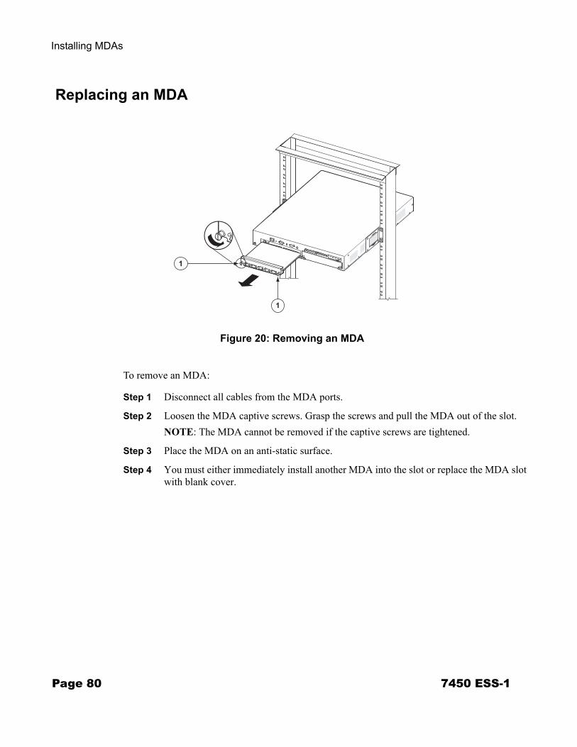
Installing MDAs
Replacing an MDA
Figure 20: Removing an MDA
To remove an MDA:
Step 1 Disconnect all cables from the MDA ports.
Step 2 Loosen the MDA captive screws. Grasp the screws and pull the MDA out of the slot.NOTE: The MDA cannot be removed if the captive screws are tightened.
Step 3 Place the MDA on an anti-static surface.
Step 4 You must either immediately install another MDA into the slot or replace the MDA slot with blank cover.
1
1
SR10025
Page 80 7450 ESS-1
Appendix A: LEDs and Optics
IN THIS CHAPTER
This section describes the front panel LEDs. MDA LEDs are described in the MDA documentation.
The following LED descriptions are included:
• Front Panel LEDs on page 82
7450 ESS-1 Page 81
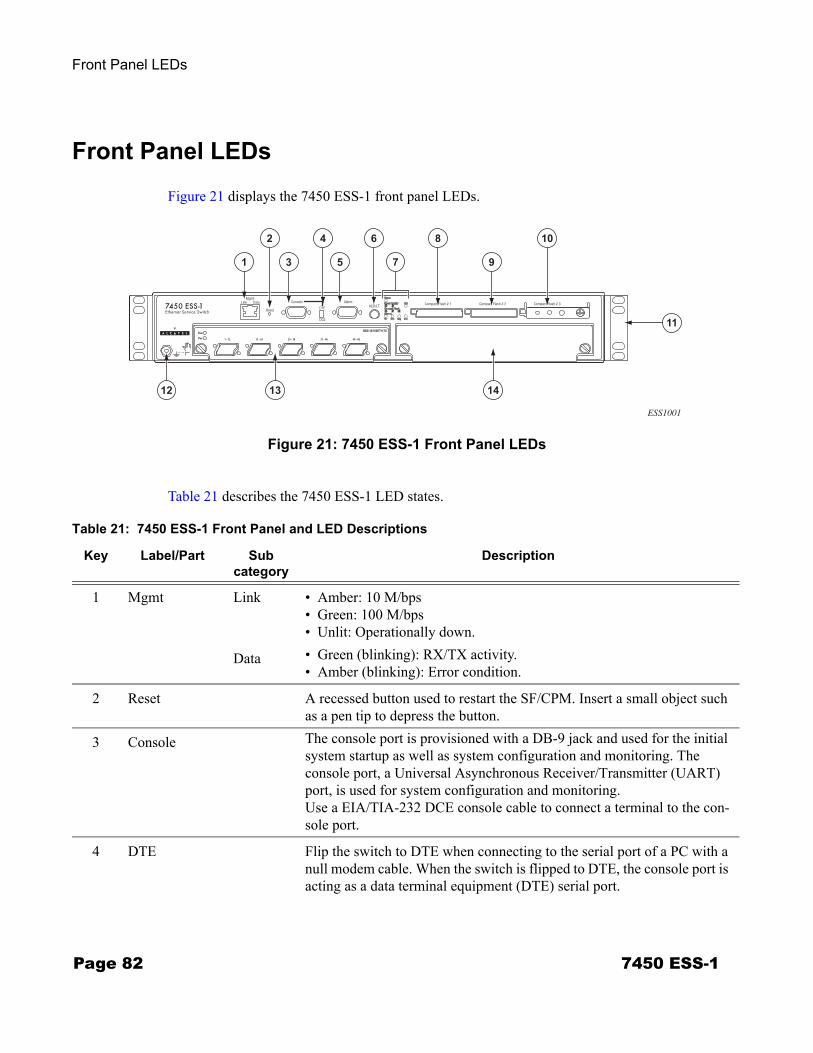
Front Panel LEDs
Front Panel LEDs
Figure 21 displays the 7450 ESS-1 front panel LEDs.
Figure 21: 7450 ESS-1 Front Panel LEDs
Table 21 describes the 7450 ESS-1 LED states.
ESS1001
2 8
9
106
7
4
31 5
141312
11
Table 21: 7450 ESS-1 Front Panel and LED Descriptions
Key Label/Part Subcategory
Description
1 Mgmt Link • Amber: 10 M/bps• Green: 100 M/bps• Unlit: Operationally down.
Data • Green (blinking): RX/TX activity.• Amber (blinking): Error condition.
2 Reset A recessed button used to restart the SF/CPM. Insert a small object such as a pen tip to depress the button.
3 Console The console port is provisioned with a DB-9 jack and used for the initial system startup as well as system configuration and monitoring. The console port, a Universal Asynchronous Receiver/Transmitter (UART) port, is used for system configuration and monitoring. Use a EIA/TIA-232 DCE console cable to connect a terminal to the con-sole port.
4 DTE Flip the switch to DTE when connecting to the serial port of a PC with a null modem cable. When the switch is flipped to DTE, the console port is acting as a data terminal equipment (DTE) serial port.
Page 82 7450 ESS-1
Appendix A: LEDs and Optics
4(cont)
DCE Flip the switch to DCE when connecting to the serial port of a PC with a straight-through cable. When the switch is flipped to DCE, the console port is acting as a data communications equipment (DCE) serial port.
5 Alarm The Alarm port is provisioned as a DB-9 serial port and is used to con-nect to external alarm devices that report conditions that trigger red or amber alarms.
6 ACO/LT The Audible Alarm Cutoff/Lamp Test button verifies the operability of LEDs. When pressed, the LEDs should temporarily illuminate. This but-ton also turns off all external alarm relay control bits until the next new alarm condition. The LEDs blink when the button is depressed.
7 Status • Green: Operationally up and administratively up.• Amber: Operationally down but administratively up.• Amber (blinking): Qualified, but previously failed.• Unlit: Not operational, shutdown, or administratively down.
Power Supply 1 • Green: Indicates that AC input power is present and operational.• Amber: Indicates an error condition with the AC input power.• Unlit: Indicates that the AC power supply is not installed or
recognized.
2 • Green: Indicates that DC input power is present and operational.• Amber: Indicates an error condition with the DC input power.• Unlit: Indicates that the DC power supply is not installed or recognized.
Fan • Green: Indicates that the fans are operational.• Amber: Indicates a fan failure.• Unlit: Indicates that the fans are not operational.
Compact Flash 1,2,3 • Green: Indicates that the flash card is operational and in a read or write process. Note: Do not physically remove or attempt to remove the flash card when the LED is lit green.
• Amber (blinking): Error condition exists. • Amber (solid): Indicates that the slot is in an operationally down mode.
This is the only mode to safely remove the flash card. • Unlit: A flash card is not installed in the slot.
Alarms OT • Red: An overtemperature condition exists. If there are no OT conditions, this LED should remain off.
Table 21: 7450 ESS-1 Front Panel and LED Descriptions (Continued)
Key Label/Part Subcategory
Description
7450 ESS-1 Page 83

Front Panel LEDs
Crit • Red: A critical condition exists, such as a severe overtemperature condition, a fan tray failure, an overcurrent condition in a power supply, or an out-of-tolerance voltage. If there are no critical conditions, this LED should remain off.
7(cont)
Maj • Red: A serious condition exists, such as an overtemperature condition, a fan tray failure, an overcurrent condition in a power supply, or an out-of-tolerance voltage. If there are no major conditions, this LED should remain off.
Min • Amber: A serious condition exists, such as a component failure. If there are no minor alarm conditions, this LED should remain off.
8 Compact Flash #1 (Slot) • Default filename: cf1:• See the Compact Flash LED description for the status of a compact
flash slot.• To remove a flash card, gently depress the ejector button until the flash
card releases.
9 Compact Flash #2 (Slot) • Default filename: cf2:• See the Compact Flash LED description for the status of a compact
flash slot. • To remove a flash card, gently depress the ejector button until the flash
card releases.
10 Compact Flash #3 (Slot) • Default filename: cf3:• The compact flash card with the boot image and configuration files
should be installed and remain in this slot.• This slot should be used to download the boot and configuration
images.• See the Compact Flash LED description for the status of a compact
flash slot.• The ejector button for Compact Flash Slot #3 is slightly recessed.
Insert a small object such as a pen tip to depress the button.
Compact flash locking mechanism
When engaged, the locking mechanism prevents the accidental jostling or removal of the flash card inserted in Compact Flash slot #3.
11 Rack mounting brackets Brackets are factory installed to front-mount the unit in a standard 19-inch wide rack
12 ESD plug Receptacle to connect an ESD wrist or ankle strap strap (with banana jack) to the ESD connection socket (grounding plug) on the front of the chassis.
Table 21: 7450 ESS-1 Front Panel and LED Descriptions (Continued)
Key Label/Part Subcategory
Description
Page 84 7450 ESS-1

Appendix A: LEDs and Optics
13 MDA (installed) Captive screws secure the MDA in place.For configuration purposes, the left MDA slot is referred to as MDA slot 1. The right MDA slot is referred to as MDA slot 2.
14 MDA slot cover Captive screws secure the cover in place.
Table 21: 7450 ESS-1 Front Panel and LED Descriptions (Continued)
Key Label/Part Subcategory
Description
7450 ESS-1 Page 85

Front Panel LEDs
Page 86 7450 ESS-1
Appendix B: Pinout Assignments
IN THIS CHAPTER
This chapter provides information about standard cable pin assignments.
Topics in this chapter include:
• Port Types on page 88• Cable Pin Assignments on page 89
→ Table 22, 10/100 Management Ethernet Port - RJ45 Female, on page 89→ Table 23, Console Port - DTE Mode - DB9 Male, on page 89→ Table 24, Console Port - DCE Mode - DB9 Male, on page 90→ Table 25, Alarm Port - DB9 Female, on page 90
7450 ESS-1 Page 87

Port Types
Port Types
Figure 22 displays the port types on the 7450 ESS-1 front panel.
Figure 22: Port Types
• The Management port is a 10/100 Ethernet port which is a channel to download images and manage the system. This port is provisioned with an RJ-45 jack on the front panel. You must provide a CAT5 Ethernet cable to connect to the port.
• The Console port is a Universal Asynchronous Receiver/Transmitter (UART) port used to configure switch and system parameters and can be also be used for monitoring purposes. The console port is enabled by default. The default Baud rate is 115,200. This port is provisioned with an DB-9 connector. Connect the console port to a terminal with an RS-232 serial cable. The DTE/DCE switch on the front panel controls the serial port type as either data terminal equipment (DTE) or data communications equipment (DCE). Flip the switch to DTE when connecting to the serial port of a PC with a null modem cable. Flip the switch to DCE when connecting to the serial port of a PC with a straight-through cable. The port is configured as DTE or DCE depending on the switch setting. No crossover cables are required.
• The Alarm port is provisioned as a DB-9 serial port and is used to connect to external alarm devices that report conditions that trigger red or amber alarms. You must provide an appropriate cable configured according to your alarm panel.
ESS1002
CONSOLEALARMMANAGEMENT
DTE/DCE SWITCH
Page 88 7450 ESS-1
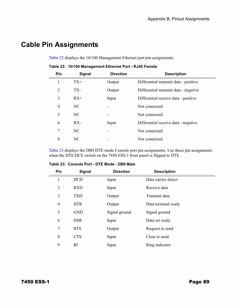
Appendix B: Pinout Assignments
Cable Pin Assignments
Table 22 displays the 10/100 Management Ethernet port pin assignments.
Table 23 displays the DB9 DTE mode Console port pin assignments. Use these pin assignments when the DTE/DCE switch on the 7450 ESS-1 front panel is flipped to DTE.
Table 22: 10/100 Management Ethernet Port - RJ45 Female
Pin Signal Direction Description
1 TX+ Output Differential transmit data - positive
2 TX- Output Differential transmit data - negative
3 RX+ Input Differential receive data - positive
4 NC - Not connected
5 NC - Not connected
6 RX- Input Differential receive data - negative
7 NC - Not connected
8 NC - Not connected
Table 23: Console Port - DTE Mode - DB9 Male
Pin Signal Direction Description
1 DCD Input Data carrier detect
2 RXD Input Receive data
3 TXD Output Transmit data
4 DTR Output Data terminal ready
5 GND Signal ground Signal ground
6 DSR Input Data set ready
7 RTS Output Request to send
8 CTS Input Clear to send
9 RI Input Ring indicator
7450 ESS-1 Page 89

Cable Pin Assignments
Table 24 displays the DB9 DCE mode Console port pin assignments. Use these pin assignments when the DTE/DCE switch on the ESS-1 front panel is flipped to DCE.
Table 25 specifies Alarm port connector pinouts. Examples of critical alarms include a fan failure, a power supply over temperature condition, and a power supply failure. The major alarm LED can illuminate when a power supply is removed. There are no conditions defined for minor alarms.
Table 24: Console Port - DCE Mode - DB9 Male
Pin Signal Direction Description
1 DCD Output Data carrier detect
2 TXD Output Transmit data
3 RXD Input Receive data
4 DSR Input Data set ready
5 GND - Signal ground
6 DTR Output Data terminal ready
7 CTS Input Clear to send
8 RTS Output Request to send
9 RI Input Ring indicator
Table 25: Alarm Port - DB9 Female
Pin Signal Direction Description
1 MAJ_COMMON Output Major alarm common
2 MAJ_NORM_CLOSED Output Major alarm normally closed
3 CRIT_NORM_OPEN Output Critical alarm normally open
4 CRIT_COMMON Output Critical alarm common
5 CRIT_NORM_CLOSED Output Critical alarm normally closed
6 MIN_NORM_OPEN Output Minor alarm normally open
7 MIN_COMMON Output Minor alarm common
8 MIN_NORM_CLOSED Output Minor alarm normally closed
9 MAJ_NORM_OPEN Output Major alarm normally open
Page 90 7450 ESS-1

Index
AAC power 53
connecting 53air flow 35
Ccable
ground wire 46compact flash 63configurations
card 72MDA 73
connectionsconsole 67Telnet 69
DDC power
input terminal block wiring 56safety cover 56
Ggrounding 35, 47
ground connection 47preparing the ground wire 46
Iinitializing the system 64
troubleshooting 64installation
footpads 44grounding 31in rack 41MDAs 77on tabletop 43power supply modules 50required tools 29
LLEDs
front panel 82status
compact flash 18, 83fan 18, 83
MMDAs
changing configuration 79configuring 73installing 76removing 79replacing 80
Ppin assignments
Alarm port 90Console port (DCE) 90Console port (DTE) 89Management port 89
powerAC 52
connecting 53CLI configuration 75DC 55
ground connection 47ground wire 46terminal block wiring 56
system requirements 32power cords 32
country-specific requirements 33power requirements 28
Rrack
clearance 30mounting 41
Ssafety considerations
grounding 35power 32
7450 ESS-1 Page 91
specificationschassis 27environmental 27
storing components 35
Uunpacking 38
Page 92 7450 ESS-1