765kv/400kv s/s powergrid raichur rev. 00 · pdf file765kv/400kv s/s powergrid raichur rev. 00...
TRANSCRIPT

Bharat Heavy Electricals Limited Doc No. TB-4-349-316-110 765kV/400kV S/S Powergrid Raichur Rev. 00 Technical Specification for Disc Insulators & String Hardware
SECTION – 1 1.1 SCOPE This technical specification covers the requirements of design, manufacture, testing at works, packing and dispatch of Disc Insulators & String Hardwares to site.
This section covers the scope and quantities of Disc Insulators & String Hardwares. The Specific Technical Requirements for the above item as specified by the customer (PGCIL) are given in Section-2. The offered equipment shall also comply with the General Technical Requirements for the project as detailed under section-3 of this specification. In case of any discrepancies between the requirements mentioned under Section-1/Section-2 and those specified in the Section-3, the specifications given under Section-1/Section-2 shall prevail and shall be treated as binding requirements. The equipment is required for the following project:
Name of the Customer : POWER GRID CORPORATION OF INDIA LIMITED (PGCIL) Name of the Project : 765kV/400kV S/S RAICHUR The scope of supplies shall be as per commercial terms and conditions enclosed separately with the enquiry. 1.2 SPECIFIC TECHNICAL REQUIREMENTS All equipment shall perform satisfactorily under various other electrical, electromechanical and meteorological conditions of the site of installation. All equipment shall be able to withstand all external and internal mechanical, thermal and electromechanical forces due to various factors like wind load, temperature variation, ice & snow, (wherever applicable) short circuit etc for the equipment. The equipment shall also comply to the following:
a) To facilitate erection of equipment, all items to be assembled at site shall be “match marked”.
Equipment and system shall be designed to meet the following major technical parameters as brought out hereunder.

Bharat Heavy Electricals Limited Doc No. TB-4-349-316-110 765kV/400kV S/S Powergrid Raichur Rev. 00 Technical Specification for Disc Insulators & String Hardware
Sl. No.
Particulars 765kV 400kV
1. System Operating Voltage 765kV 400kV
2. Maximum Operating voltage of the system (rms) 800kV 420kV
3. Rated Frequency 50Hz 50Hz
4. No of phase 3 3
5. Rated Insulation Levels
i) Full Wave impulse withstand voltage (1.2/50 microsec.)
2100 kVp 1550 kVp
ii) Switching impulse withstand voltage (250/2500 micro sec.) dry and wet
1550 kVp 1050 kVp
iii) One minute power frequency dry withstand voltage (rms)
870 kV 680 kV
iv) One minute power frequency dry and wet withstand voltage (rms)
6. Corona Extinction voltage 508 kV 320 kV
7. Max. radio interference voltage for frequency between 0.5MHz and 2 MHz at 508 kV rms for 765kV, 266kV rms for 400kV system and 156kV rms for 220kV system.
2500 micro volts 1000 micro volts
8. Minimum creepage system (25mm/kV) 20000 mm 10500 mm
9. Min. Clearance
i) Phase to Phase 7600 mm (for conductor-conductor
configuration) 9400mm (for rod-
conductor
4000mm (for conductor-conductor
configuration) 4200mm (for
rod-conductor
Bharat Heavy Electricals Limited Doc No. TB-4-349-316-110 765kV/400kV S/S Powergrid Raichur Rev. 00 Technical Specification for Disc Insulators & String Hardware
configuration) configuration)
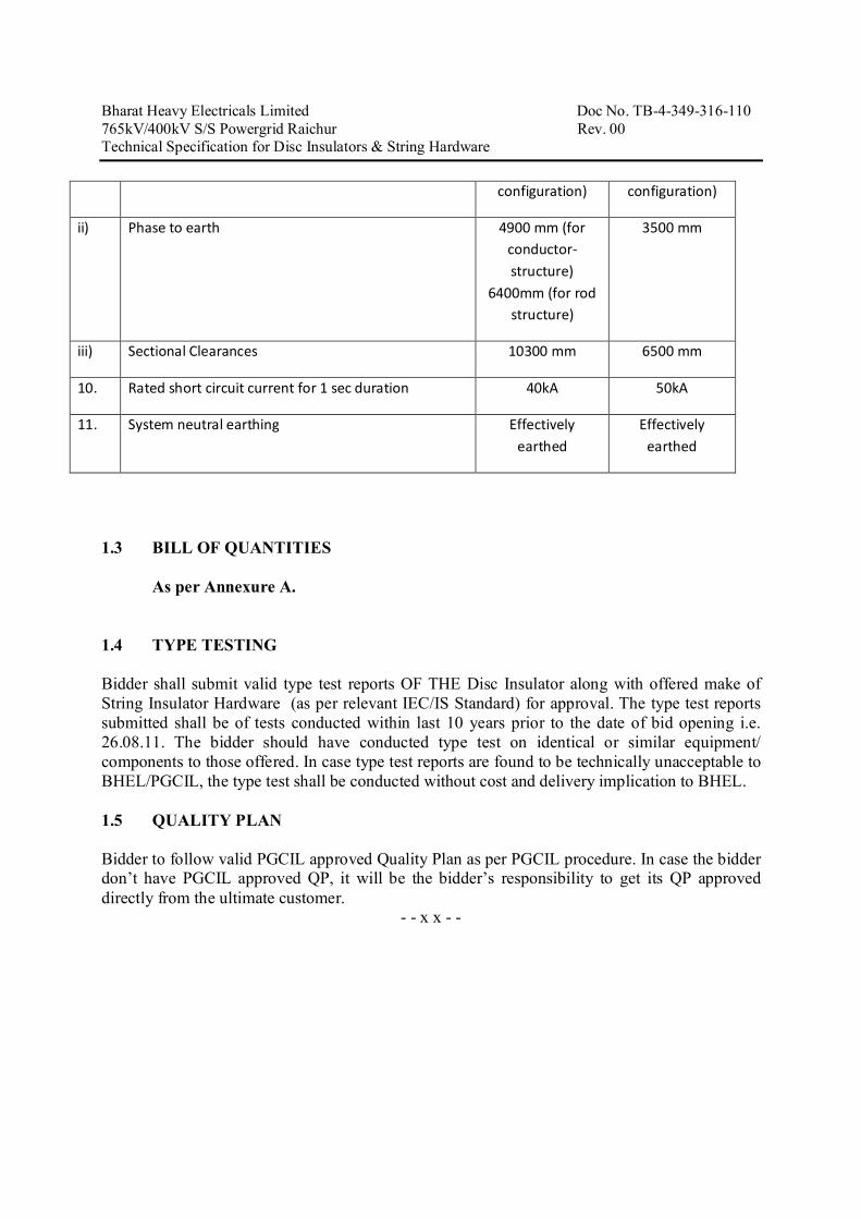
ii) Phase to earth 4900 mm (for conductor-structure)
6400mm (for rod structure)
3500 mm
iii) Sectional Clearances 10300 mm 6500 mm
10. Rated short circuit current for 1 sec duration 40kA 50kA
11. System neutral earthing Effectively earthed
Effectively earthed
1.3 BILL OF QUANTITIES
As per Annexure A.
1.4 TYPE TESTING Bidder shall submit valid type test reports OF THE Disc Insulator along with offered make of String Insulator Hardware (as per relevant IEC/IS Standard) for approval. The type test reports submitted shall be of tests conducted within last 10 years prior to the date of bid opening i.e. 26.08.11. The bidder should have conducted type test on identical or similar equipment/ components to those offered. In case type test reports are found to be technically unacceptable to BHEL/PGCIL, the type test shall be conducted without cost and delivery implication to BHEL. 1.5 QUALITY PLAN Bidder to follow valid PGCIL approved Quality Plan as per PGCIL procedure. In case the bidder don’t have PGCIL approved QP, it will be the bidder’s responsibility to get its QP approved directly from the ultimate customer.
- - x x - -

Project: 765kV/400kV Raichur Project BOQ FOR DISC INSULATORS AND STRING INSULATOR HARDWARE
Sl. No. Item DescriptionQty.of string hardware
Spare Qty(5%) hardware
Total (Qty) of string hardware
1765kV Double tension insulator string (comprising 2x47 discs) with subconductor spacing 450mm suitable for quad AAC Bull conductor with turn Buckle
51 3 54
2765kV Double tension insulator string (comprising 2x47 discs) with subconductor spacing 450mm suitable for quad AAC Bull conductor with out turn Buckle
48 3 51
3765kV Single suspension insulator string (comprising 1x47 discs) with subconductor spacing 450mm suitable for quad AAC Bull conductor with drop clamp
27 2 29
4765kV Single suspension insulator string (comprising 1x47 discs) with subconductor spacing 450mm suitable for quad AAC Bull conductor with straight clamp
24 2 26
5400kV Double tension insulator string (comprising 2x25 discs) with subconductor spacing 450mm suitable for quad ACSR Bersimis conductor with turn Buckle
72 5 77
6 400kV Double tension insulator string (comprising 2x25 discs) with subconductor spacing 450mm suitable for quad ACSR Bersimis conductor with out turn Buckle
60 4 64
7400kV Single suspension insulator string (comprising 1x25 discs) with subconductor spacing 450mm suitable for quad ACSR Bersimis conductor with drop clamp
54 3 57
8 400kV Single suspension insulator string (comprising 1x25 discs) with subconductor spacing 450mm suitable for quad ACSR Bersimis conductor with straight clamp
12 1 13
9 400kV Double tension insulator string (comprising 2x25 discs) with subconductor spacing 450mm suitable for quad AAC Bull conductor with turn Buckle
12 1 13
10 400kV Double tension insulator string (comprising 2x25 discs) with subconductor spacing 450mm suitable for quad AAC Bull conductor with out turn Buckle
12 1 13
11 Disc Insulator 21153 1058 22211

Bharat Heavy Electricals Limited Doc No. TB-4-349-316-110 765kV/400kV S/S Powergrid Raichur Rev. 00 Technical Specification for Disc Insulators & String Hardware
SECTION – 2
2.1 String Insulators & Hardware
The Insulators for suspension and tension strings shall conform to IEC-60383 and long rod insulators shall conform to IEC-60433. Insulator hardware shall conform to IS:2486.
2.1.1 Construction Features
2.1.1.1 For porcelain insulators
a) Suspension and tension insulators shall be wet process porcelain with ball and socket connection. Insulators shall be interchangeable and shall be suitable for forming either suspension or tension strings. Each insulator shall have rated strength marking on porcelain printed and applied before firing.
b) Porcelain used in insulators manufacture shall be homogeneous, free from laminations, cavities and other flaws or imperfections that might affect the mechanical or dielectric quality and shall be thoroughly vitrified, tough and impervious to moisture.
c) Glazing of the porcelain shall be uniform brown colour, free from blisters, burrs and other similar defects.
2.1.1.2 For glass insulators
It shall be made of toughened glass. Glass used for the shells shall be sound, free from defects, flows bubbles, inclusions, etc and be of uniform toughness over its entire surface. All exposed glass surfaces shall be smooth.
2.1.1.3 When operating at normal rated voltage there shall be no electric discharge between conductor and insulator which would cause corrosion or injury to conductors or insulators by the formation of substances due to chemical action. No ratio interference shall be caused when operating at normal rated voltage.
2.1.1.4 The design of the insulator shall be such that stresses due to expansion and contraction in any part of the insulator shall not lead to deterioration. All ferrous parts shall be hot dip galvanized in accordance with latest edition of IS: 2629. The zinc used for galvanized shall be of grade Zn- 99.95 as per IS-209. The zinc coating shall be uniform, adherent, smooth, reasonably bright, continuous and free from imperfections such as flux, ash, rust stains bulky white deposits and blisters.
2.1.1.5 Bidder shall make available date on all the essential features of design including the method of assembly of discs and metal parts, number of discs per insulator string insulator, the manner in which mechanical stresses are transmitted through discs to adjacent parts, provision for

Bharat Heavy Electricals Limited Doc No. TB-4-349-316-110 765kV/400kV S/S Powergrid Raichur Rev. 00 Technical Specification for Disc Insulators & String Hardware meeting expansion stresse, results of corona and thermal shock tests, recommended working strength and any special design or arrangement employed to increase life under service conditions.
2.1.1.6 Clamps for insulator strings and corona Control rings shall be of aluminium alloy as stipulated for clamps and connectors.
2.1.1.7 Insulators hardware shall be of forged steel. Malleable cast iron shall not be accepted except for insulator disc cap. The surface of hardware must be clean, smooth, without cuts, abrasion or projections. No Part shall be subjected to excessive localized pressure. The metal parts shall not produce any noise generating corona under operating conditions.
2.1.1.8 The tension Insulator hardware assembly shall be designed for minimum 12000 kg tensile load. Earth wire tension clamp shall be designed for minimum 1000 kg tensile load with a factor of safety of two (2).
2.1.1.9 The tension string assemblies shall be supplied alongwith suitable turn buckle Sag compensation spring if required may also be provided.
2.1.1.10 All hardware shall be bolted type.
2.2 Long Rod Insulators
2.2.1 As an alternative to disc insulator, Bidder can offer long rod porcelain/composite insulator strings, with suitable hardware. The combination should be suitable for application specified and should offer the identical/equivalent parameters as would be available from insulator string comprising disc insulators and hardware combination.
2.2.2 All constructional features specified at Clause 1.1.1 of this Section shall also apply to the rod insulator String.
2.3 Tests
In accrdance with the stipulations of the specification, the suspension and tension strings, insulator and hardware shall be subjected to the following type tests, acceptance tests and routine tests:
2.3.1 Type Tests on Insulator Strings : The test reports for following type tests shall be submitted for approval as per clause 9.2 of section – GTR.
a) Power frequency voltage withstand test with corona control rings under wet condition as per IEC-60383

Bharat Heavy Electricals Limited Doc No. TB-4-349-316-110 765kV/400kV S/S Powergrid Raichur Rev. 00 Technical Specification for Disc Insulators & String Hardware
b) Switching surge voltage withstand test (400 kV and above class only) under wet condition as per IEC-60383
c) Lightning Impulse Voltage withstand test with corona control rings under dry condition as per IEC-60383
d) Voltage distribution test (Dry) The Voltage across each insulator unit shall be measured by sphere gap method. The result obtained shall be converted into percentage. The voltage across any disc shall not exceed 6.5% for 765 kV Suspension and tension insulator strings, 9% and 10% for 400KV suspension string and tension insulator string respectively.
e) Corona Extinction Voltage test (Dry) The sample assembly when subjected to power frequency voltage shall have a corona extinction voltage of not less than 508 kV (rms) for 765 kV, 320kV (rms) for 400kV line to ground under dry condition. There shall be no evidence on Corona on any part the sample. The atmospheric condition during testing shall be recorded and the test results shall be accordingly corrected with suitable correction factor as stipulated in IEC 60383.
f) RIV Test (Dry) Under the conditions as specified under (e) above the insulator string along with complete hardware fittings shall have a radio interference voltage level below 2500 microvolts at 1 MHz when subjected to 50Hz AC line to ground voltage of 508 kV for 765 kV and 1000 microvolts at 1 MHz when subjected to 50Hz AC line to ground voltage of 320kV for 400kV string under dry conditions. The test procedure shall be in accordance with IS 8263/IEC 60437.
g) Mechanical strength test The complete insulator string alongwith its hardware fitting excluding arcing horn, corona control ring, grading ring, tension/suspension clamps shall be subjected to a load equal to 50% of the specified minimum ultimate tensile strenght (UTS) which shall be increased at a steady rate to 67% of the minimum UTS specified. The load shall be held for five minutes and then removed. After removal of the load, the string components shall not show any visual deformation and it shall be possible to dismantle them by hand. Hand tools may be used to remove cotter pins and loosen the nuts initially. The string shall then be reassembled and loaded to 50% of UTS and the load shall be further increased at a steady rate till the specified minimum UTS and held for one minute. No fracture should occur during this period. The applied load shall then be increased until the failling load is reached and the value recorded.

Bharat Heavy Electricals Limited Doc No. TB-4-349-316-110 765kV/400kV S/S Powergrid Raichur Rev. 00 Technical Specification for Disc Insulators & String Hardware 2.3.2 Type Tests on Insulators
Type test report for Thermal Mechanical Performance tests as per IEC 60575, Clause 3 / IEC: 61109, clause 5.1 (for composite long rod insulators) shall be submitted for approval as per clause 9.2 of Section GTR.
2.3.3 Acceptance Tests for Insulators:-
a) Visual examination as per IEC-60383/ IEC-61109 clause no. 7.2 (for composite long rod insulators).
b) Verification of Dimensions as per IEC-60383. c) Temperature cycle test as per IEC-60383. d) Puncture Test as per IEC-60383 (Applicable only for porcetain insulators) e) Galvanizing Test as per IEC-60383. f) Mechanical performance test as per IEC-60575 Cl. 4 / IEC-61109 clause no. 7.2 (for
composite long rod insulators). g) Test on locking device for ball and socket coupling as per IEC-60372 (2) h) Porosity test as per IEC- 60383 (Applicable only for porcelain insulators). i) Thermal shock test as per IEC-60383 (Applicable only for glass insulators).
2.3.4 Acceptance Test on Hardware Fitting :-
a) Visual Examination as per Cl. 5.10 of IS: 2486 (Part-1). b) Verification of Dimensions as per Cl. 5.8 of IS: 2486 (Part-1). c) Galvanising/Electroplating tests as per Cl. 5.9 of IS: 2486 (Part-1). d) Slip strenght test as per Cl. 5.4 of IS: 2486 (Part-1). e) Shore hardness test for the Elastometer (if applicable as per the value guaranteed by the
Bidder). f) Mechanical strength test for each component (including corona control rings and arccing
horns). The load shall be so applied that the component is stressed in the same way as it would be in actual service and the procedure as given in 1.2.13.1 (g) above should be followed.
g) Test on locking devices for ball and socket coupling as per IEC – 60372 (2).
2.3.5 Routine Test on Insulator
a) Visual Inspection as per IEC- 60383 b) Mechnical Routine Test as per IEC – 60383 c) Electrical Routine Test as per IEC – 60383

Bharat Heavy Electricals Limited Doc No. TB-4-349-316-110 765kV/400kV S/S Powergrid Raichur Rev. 00 Technical Specification for Disc Insulators & String Hardware 2.3.6 Routine Test on hardware Fittings
a) Visual examination as per Cl. 5.10 of IS: 2486 (part-I) / IEC-61109 (for composite long rod insulators).
b) Mechanical strenth Test as per Cl. 5.11 of IS: 2486 (part-I) / IEC-61109 (for composite long rod insulators).
2.3.7 Test during manufacture on all components as applicable on Isolator :
a) Chemical analysis of zinc used for galvanising:- Sample taken from the zinc ingot shall be chemically analyzed as per IS: 209. The purity of zinc shall not be less than 99.95%
b) Chemical Analysis, Mechanical hardness tests and magnetic particle inspection for malleable casting:- The chemical analysis, hardness tests and magnetic particle inspection for malleable casting will be as per the internationally recognized procedures for these tests. The sampling will be based on heat number and heat treatment batch. The details regarding tests will be as discussed and mutually agreed to by the Contractor and Owner in Quality Assurance Program.
2.3.8 Test during manufacture on all components as applicable on hardware fittings:
a) Chemical analysis of zinc used for galvanising: Sample taken from the zinc ingot shall be chemically analyzed as per IS: 209. The purity of zinc shall not be less than 99.95%
b) Chemical Analysis, hardness tests and magnetic particle for forgings: The chemical analysis, hardness tests and magnetic particle inspection for forgings will be as per the internationally recognized procedures for these tests. The sampling will be based on heat number and heat treatment batch. The details regarding tests will be as discussed and mutually agreed to by the Contractor and Owner in Quality Assurance Program.
c) Chemical Analysis, Mechanical hardness tests and magnetic particle inspection for fabricated hardware:
The chemical analysis, hardness tests and magnetic particle inspection for fabricated hardware will be as per the internationally recognized procedures for these tests. The sampling will be based on heat number and heat treatment batch. The details regarding tests will be as discussed and mutually agreed to by the Contractor and Owner in Quality Assurance Program.
2.4 Parameters
2.4.1 Disc Insulators
a) Type of insulators : Anti Fog type

Bharat Heavy Electricals Limited Doc No. TB-4-349-316-110 765kV/400kV S/S Powergrid Raichur Rev. 00 Technical Specification for Disc Insulators & String Hardware
b) Size of insulator units (mm) : 255×145 or 280×145 c) Electro mechanical strength : 120 KN d) Creepage distance of individual
insulator units (minimum and as : 430 mm required to meet total creepage distance)
e) Markings 1) For Porcelain insulators : Markings on porcelain shall be printed and
applied before firing 2) For toughened glass insulators : Markings shall be done on initial parts
f) Power frequency puncture : 1.3 times the actual wet flashover voltage. Withstand voltage
*Long rod porcelain/composite insulators should conform to equipment electrical and mechanical parametrers.
2.4.2 INSULATOR STRING
For tension application, double insulator strings and for suspension purpose single suspension insulator string shall be used for 765 kV and 400 kV systems.
SI. No. Description 765 kV 400kV a) Power frequency withstand voltage of the complete
string with corona control ring (wet)-kV rms 870 680
b) Lightning impulse withstand Voltage of string with corona control rings (dry) –kVp
±2100 ±1550
c) Switching surge withstand voltage of string with corona control rings (wet) –kVp
±1550 ±1050
d) Minimum corona extinction voltage level of string with Corona Control rings (dry) –kV rms
508 320
e) Maximum RIV level in micro volts of string with Corona Control rings at 508 kV (rms) for 765 kV, 320 kV (rms) for 400 kV string across300 Ohms resistor at 1 MHz
2500 1000
f) Minimum total creepage distance of the insulator string (mm)
20000 10500
g) Total no. of discs per strings 47 25

Bharat Heavy Electricals Limited Doc No. TB-4-349-316-110 765kV/400kV S/S Powergrid Raichur Rev. 00 Technical Specification for Disc Insulators & String Hardware
Page 1
SECTION-3
PROJECT DETAILS & GENERAL SPECIFICATION ---------------------------------------------------------------------------------------------------------
SITE INFORMATION
Particular Details
a) Customer Power Grid Corporation of India Limited
b) Project Title
765kV/400kV Substation at Raichur
c) Location
RAICHUR(KARNATAKA)
d) Transport Facilities
ROAD/TRAIN Nearest Airport Hyderabad
SITE CONDITIONS
a) Max. ambient air temp. 50C b) Min. ambient air temp. 0C c) Max. design ambient temp. 50C d) Design reference temp. 50C e) Average Humidity Max. 100%
f) Special corrosion conditions No
g) Solar Radiation 1.2kW/sqmtr
h) Atmospheric UV radiation High
i) Altitude above sea level Less than 1000meter
j) Pollution Severity High Pollution level (25mm/kV)
k) Seismic Zone
As per the seismic zone defined in the relevant BIS but not less than 0.3g horizontal
WIND DATA Wind velocity As per IS Average No. of thunderstorm
days per annum
As per IS

Bharat Heavy Electricals Limited Doc No. TB-4-349-316-110 765kV/400kV S/S Powergrid Raichur Rev. 00 Technical Specification for Disc Insulators & String Hardware
Page 2
1.0 GENERAL
This Chapter covers Technical Requirements and requirements of auxiliary items.
a) Equipment furnished shall be complete in every respect with all mountings, fittings, fixtures and standard accessories normally provided with such equipment and/or needed for erection, completion and safe operation of the equipment as required by applicable codes unless included in the list of exclusions.
b) Material and components not specifically stated in this specification but which are
necessary for satisfactory operation of the equipment and accessories specified in this specification shall be deemed to be included unless specifically excluded and shall be supplied at no extra cost.
c) Whenever a material or article is specified or described by the name of a particular
brand, manufacturer or vendor, the specific name mentioned shall be understood as establishing type, function and quality and not as limiting competition.
d) In case any Deviation Schedule, Bid Proposal Sheet, Schedule of Data
Requirements (DRS), test reports or any other document/information are not furnished along-with the bid, the bid is liable to be rejected. Unless brought out clearly, the Bid will be deemed to conform to the specification scrupulously. All deviations from the specification shall be clearly brought out in the respective deviation schedule.
e) Auxiliary supplies as described below would be available at site.
Normal Variation Frequency Phase Neutral Voltage in voltage (Hz) connection (Volts) ------------------------------------------------------------------------------------ 415 + 10 % 50 + 5 % 3 Ph- 4wire Solidly earthed 240 + 10 % 50 + 5 % 1 Solidly earthed 220 + 10 % DC - Isolated (2 wire system) ------------------------------------------------------------------------------------
f) The Bidder shall clearly indicate in the bid, the specific standards in accordance
with which the works will be carried out. g) The equipment must be new, of highest grade, the best quality of their kind, to
best engineering practice and latest state of art, and in accordance with purpose for which they are intended and ensure satisfactory performance throughout the service life.
h) All similar parts of the equipment shall be made to gauge and shall be
interchangeable with and shall be made of same materials and workmanship as the corresponding parts of the equipment. Where feasible, common components, units shall be employed in different pieces of equipment in order to optimize the spare part stock-up and utilization.
i) The requirement regarding external RIV as specified for equipment shall include the
terminal fittings and the equipment shall have been tested preferably with fittings, if any.

Bharat Heavy Electricals Limited Doc No. TB-4-349-316-110 765kV/400kV S/S Powergrid Raichur Rev. 00 Technical Specification for Disc Insulators & String Hardware
Page 3
2.0 SERVICES TO BE PERFORMED BY THE EQUIPMENT BEING FURNISHED
a) The equipment furnished under this specification shall perform all its functions and operate satisfactorily without showing undue strain, restrike etc.
b) The equipment shall be able to withstand forces due to wind load, short circuit,
system over voltages, fluctuations, frequency variations etc., all forces considered together.
3.0 SUPPORT STRUCTURES (If in the scope of Bidder)
a) The support structures should be hot dip galvanised with minimum 610 gram/m2 net
of zinc. b) The design calculations taking into account the environmental conditions of the
substations shall be furnished for sizing of the structures.
4.0 STANDARDS
a) The equipment to be furnished under this specification shall conform to latest issue
with all amendments of standard specified under respective Chapters of this Specification. The Bidder shall note that standards mentioned in the specification are not mutually exclusive or complete in themselves, but intended to complement each other. The Contractor shall also note that list of standards presented in this specification is not complete. Whenever necessary the list of standards shall be considered in conjunction with specific IS/IEC. When the specific requirements stipulated in the specifications exceed or differ than those required by the applicable standard, the stipulation of the specification shall take precedence.
b) Other internationally accepted standards which ensure equivalent or better
performance than that specified in the standards referred shall also be accepted. c) In case governing standards for the equipment is different from IS or IEC, the
salient points of difference shall be clearly brought out in additional information schedule along with English language version of standard or relevant extract of the same. The equipment conforming to standards other than IS/IEC shall be subject to Employer’s approval.
5.0 ENGINEERING DATA AND DRAWINGS
5.1 The list of drawings/documents which are to be submitted to the Purchaser shall be
discussed and finalized by the Purchaser at the time of award.
The Contractor shall necessarily submit all the drawings/documents unless anything is waived.
5.2 The Contractor shall submit 4 (four) sets of drawings/ design documents /data
/ detailed bill of quantity and 1 (one) set of test reports for the approval of the Purchaser. The contractor shall also submit the softcopy of the above documents in addition to hardcopy.
5.3 Drawings
5.3.1 All drawings submitted by the Contractor shall be in sufficient detail to indicate the
type, size, arrangement, material description, Bill of Materials, weight of each component, break-up for packing and shipment, dimensions, internal & the

Bharat Heavy Electricals Limited Doc No. TB-4-349-316-110 765kV/400kV S/S Powergrid Raichur Rev. 00 Technical Specification for Disc Insulators & String Hardware
Page 4
external connections, fixing arrangement required and any other information specifically requested in the specifications.
5.3.2 Drawings submitted by the Contractor shall be clearly marked with the name of the
Purchaser, the unit designation, the specifications title, the specification number and the name of the Project. POWERGRID has standardized a large number of drawings/documents of various make including type test reports which can be used for all projects having similar requirements and in such cases no project specific approval (except for list of applicable drawings along with type test reports) is required. However, distribution copies of standard drawings/documents shall be submitted as per provision of the contract. All titles, noting, markings and writings on the drawing shall be in English. All the dimensions should be in SI units.
5.3.3 The review of these data by the Purchaser will cover only general conformance of the
data to the specifications and documents, interfaces with the equipment provided under the specifications, external connections and of the dimensions which might affect substation layout. This review by the Purchaser may not indicate a thorough review of all dimensions, quantities and details of the equipment, materials, any devices or items indicated or the accuracy of the information submitted. This review and/or approval by the Purchaser shall not be considered by the Contractor, as limiting any of his responsibilities and liabilities for mistakes and deviations from the requirements, specified under these specifications and documents.
5.5 All manufacturing and fabrication work in connection with the equipment prior to the approval of the drawings shall be at the Contractor’s risk. The Contractor may make any changes in the design which are necessary to make the equipment conform to the provisions and intent of the Contract and such changes will again be subject to approval by the Purchaser. Approval of Contractor’s drawing or work by the Purchaser shall not relieve the contractor of any of his responsibilities and liabilities under the Contract.
5.6 All engineering data submitted by the Contractor after final process including
review and approval by the Purchaser shall form part of the Contract Document and the entire works performed under these specifications shall be performed in strict conformity, unless otherwise expressly requested by the Purchaser in Writing.
5.7 Approval Procedure
The scheduled dates for the submission of the drawings as well as for, any data/information to be furnished by the Purchaser would be discussed and finalised at the time of award. The following schedule shall be followed generally for approval and for providing final documentation.
i) Approval/comments/ As per agreed by
Purchaser on initial schedule submission
ii) Resubmission Within 3 (three) weeks
(whenever from date of comments required)
iii) Approval or comments Within 3 (three) weeks of
receipt of resubmission.
iv) Furnishing of distribution 2 weeks from the date copies (5 hard copies per of approval substation and one scanned copy (pdf format) for Corporate Centre)

Bharat Heavy Electricals Limited Doc No. TB-4-349-316-110 765kV/400kV S/S Powergrid Raichur Rev. 00 Technical Specification for Disc Insulators & String Hardware
Page 5
v) Furnishing of distribution copies of test reports (a) Type test reports 2 weeks from the date
(one scanned softcopy in of final approval pdf format per substation plus one for corporate centre & one hardcopy per substation)
(b) Routine Test Reports -do-
(one copy for each substation)
vi) Furnishing of instruction/ As per agreed schedule
operation manuals (2 copies per substation and one softcopy (pdf format) for corporate centre & per substation)
(vii) As built drawings (two sets of On completion of entire works
hardcopy per substation & one softcopy (pdf format) for corporate centre& per substation)
NOTE :
(1) The contractor may please note that all resubmissions must incorporate all
comments given in the earlier submission by the Purchaser or adequate justification for not incorporating the same must be submitted failing which the submission of documents is likely to be returned.
(2) All drawings should be submitted in softcopy form, however substation
design drawings like SLD, GA, all layouts etc. shall also be submitted in AutoCAD Version. SLD, GA & layout drawings shall be submitted for the entire substation in case of substation extension also.
(3) The instruction Manuals shall contain full details of drawings of all equipment
being supplied under this contract, their exploded diagrams with complete instructions for storage, handling, erection,commissioning, testing, operation, trouble shooting, servicing and overhauling procedures.
(4) If after the commissioning and initial operation of the substation,
the instruction manuals require any modifications/ additions/changes, the same shall be incorporated and the updated final instruction manuals shall be submitted by the Contractor to the Purchaser.
(5) The manufacturer shall furnish to the Purchaser catalogues of spare parts.
(6) All As-built drawings/documents shall be certified by site indicating the changes
before final submission.
6.0 MATERIAL WORKMANSHIP
6.1 General Requirement 6.1.1 Where the specification does not contain references to workmanship, equipment,
materials and components of the covered equipment, it is essential that the same must be new, of highest grade of the best quality of their kind, conforming to best engineering practice and suitable for the purpose for which they are intended.
6.1.2 Incase where the equipment, materials or components are indicated in the specification as “similar” to any special standard, the Purchaser shall decide upon the question of similarity. When required by the specification or when required by

Bharat Heavy Electricals Limited Doc No. TB-4-349-316-110 765kV/400kV S/S Powergrid Raichur Rev. 00 Technical Specification for Disc Insulators & String Hardware
Page 6
the Purchaser the Contractor shall submit, for approval, all the information concerning the materials or components to be used in manufacture. Machinery, equipment, materials and components supplied, installed or used without such approval shall run the risk of subsequent rejection, it being understood that the cost as well as the time delay associated with the rejection shall be borne by the Contractor.
6.1.3 The design of the Works shall be such that installation, future expansions, replacements and general maintenance may be undertaken with a minimum of time and expenses. Each component shall be designed to be consistent with its duty and suitable factors of safety, subject to mutual agreements. All joints and fastenings shall be devised, constructed and documented so that the component parts shall be accurately positioned and restrained to fulfill their required function. In general, screw threads shall be standard metric threads. The use of other thread forms will only be permitted when prior approval has been obtained from the Purchaser.
6.1.4 Whenever possible, all similar part of the Works shall be made to gauge and shall also be made interchangeable with similar parts. All spare parts shall also be interchangeable and shall be made of the same materials and workmanship as the corresponding parts of the Equipment supplied under the Specification. Where feasible, common component units shall be employed in different pieces of equipment in order to minimize spare parts stocking requirements. All equipment of the same type and rating shall be physically and electrically interchangeable.
6.1.5 All materials and equipment shall be installed in strict accordance with the manufacturer’s recommendation(s). Only first-class work in accordance with the best modern practices will be accepted. Installation shall be considered as being the erection of equipment at its permanent location. This, unless otherwise specified, shall include unpacking, cleaning and lifting into position, grouting, levelling, aligning, coupling of or bolting down to previously installed equipment bases/foundations, performing the alignment check and final adjustment prior to initial operation, testing and commissioning in accordance with the manufacturer’s tolerances, instructions and the Specification. All factory assembled rotating machinery shall be checked for alignment and adjustments made as necessary to re-establish the manufacturer’s limits suitable guards shall be provided for the protection of personnel on all exposed rotating and / or moving machine parts and shall be designed for easy installation and removal for maintenance purposes. The spare equipment(s) shall be installed at designated locations and tested for healthiness.
6.1.6 The Contractor shall apply oil and grease of the proper specification to suit the machinery, as is necessary for the installation of the equipment. Lubricants used for installation purposes shall be drained out and the system flushed through where necessary for applying the lubricant required for operation. The Contractor shall apply all operational lubricants to the equipment installed by him.
6.1.7 All oil, grease and other consumables used in the Works/ Equipment shall be purchased in India unless the Contractor has any special requirement for the specific application of a type of oil or grease not available in India. In such is the
case he shall declare in the proposal, where such oil or grease is available. He shall help Purchaser in establishing equivalent Indian make and Indian Contractor. The same shall be applicable to other consumables too.
6.1.8 Corona and radio interference voltage test and seismic withstand test (for 132kV and above voltage level) procedures for equipments shall be in line with the procedure given at Annexure-A and B respectively.
6.2 Provisions For Exposure to Hot and Humid climate

Bharat Heavy Electricals Limited Doc No. TB-4-349-316-110 765kV/400kV S/S Powergrid Raichur Rev. 00 Technical Specification for Disc Insulators & String Hardware
Page 7
Outdoor equipment supplied under the specification shall be suitable for service and storage under tropical conditions of high temperature, high humidity, heavy rainfall and environment favourable to the growth of fungi and mildew. The indoor equipments located in non-air conditioned areas shall also be of same type.
6.2.1 Space Heaters
6.2.1.1 The heaters shall be suitable for continuous operation at 240V as supply voltage. On-off switch and fuse shall be provided.
6.2.1.2 One or more adequately rated thermostatically connected heaters shall be supplied to prevent condensation in any compartment. The heaters shall be installed in the compartment and electrical connections shall be made sufficiently away from below the heaters to minimize deterioration of supply wire insulation. The heaters shall be suitable to maintain the compartment temperature to prevent condensation.
6.2.1.3 Suitable anti condensation heaters with the provision of thermostat shall be provided.
6.2.2 FUNGI STATIC VARNISH
Besides the space heaters, special moisture and fungus resistant varnish shall be applied on parts which may be subjected or predisposed to the formation of fungi due to the presence or deposit of nutrient substances. The varnish shall not be applied to any surface of part where the treatment will interfere with the operation or performance of the equipment. Such surfaces or parts shall be protected against the application of the varnish.
6.2.3 Ventilation opening
Wherever ventilation is provided, the compartments shall have ventilation openings with fine wire mesh of brass to prevent the entry of insects and to reduce to a minimum the entry of dirt and dust. Outdoor compartment openings shall be provided with shutter type blinds and suitable provision shall be made so as to avoid any communication of air / dust with any part in the enclosures of the Control Cabinets, Junction boxes and Marshalling Boxes, panels etc.
6.2.4 Degree of Protection
The enclosures of the Control Cabinets, Junction boxes and Marshalling Boxes, panels etc. to be installed shall provide degree of protection as detailed here under:
a) Installed out door: IP- 55
b) Installed indoor in air conditioned area: IP-31
c) Installed in covered area: IP-52
d) Installed indoor in non air conditioned area where possibility of entry of water is limited: IP-41.
e) For LT Switchgear (AC & DC distribution Boards) : IP-52 The degree of protection shall be in accordance with IS:13947 (Part-I) / IEC-60947 (Part-I) / IS 12063 / IEC-60529. Type test report for degree of protection test, shall be submitted for approval.
6.3 RATING PLATES, NAME PLATES AND LABELS
6.3.1 Each main and auxiliary item of substation is to have permanently attached to it in a conspicuous position a rating plate of non-corrosive material upon which is to be engraved manufacturer’s name, year of manufacture, equipment name, type or serial number together with details of the loading conditions under which the item of substation in question has been designed to operate, and such diagram plates as

Bharat Heavy Electricals Limited Doc No. TB-4-349-316-110 765kV/400kV S/S Powergrid Raichur Rev. 00 Technical Specification for Disc Insulators & String Hardware
Page 8
may be required by the Purchaser. The rating plate of each equipment shall be according to IEC requirement.
6.3.2 All such nameplates, instruction plates, rating plates of transformers, reactors, CB, CT, CVT, SA, Isolators, C & R panels and PLCC equipments shall be bilingual with Hindi inscription first followed by English. Alternatively two separate plates one with Hindi and the other with English inscriptions may be provided.
6.4 FIRST FILL OF CONSUMABLES, OIL AND LUBRICANTS
All the first fill of consumables such as oils, lubricants, filling compounds, touch up paints, soldering/brazing material for all copper piping of circuit breakers and essential chemicals etc. which will be required to put the equipment covered under the scope of the specifications, into successful Operation, shall be furnished by the Contractor unless specifically excluded under the exclusions in these specifications and documents.
7.0 DESIGN IMPROVEMENTS / COORDINATION
7.1 The bidder shall note that the equipment offered by him in the bid only shall be accepted for supply. However, the Purchaser or the Contractor may propose changes in the specification of the equipment or quality thereof and if the Purchaser & contractor agree upon any such changes, the specification shall be modified accordingly.
7.2 If any such agreed upon change is such that it affects the price and schedule of completion, the parties shall agree in writing as to the extent of any change in the price and/or schedule of completion before the Contractor proceeds with the change. Following such agreement, the provision thereof, shall be deemed to have been amended accordingly.
7.3 The Contractor shall be responsible for the selection and design of appropriate equipments to provide the best co-ordinated performance of the entire system. The basic design requirements are detailed out in this Specification. The design of various components, sub-assemblies and assemblies shall be so done that it facilitates easy field assembly and maintenance.
7.4 The Contractor has to coordinate designs and terminations with the agencies (if any) who are Consultants/Contractor for the Purchaser. The names of agencies shall be intimated to the successful bidders.
7.5 The Contractor will be called upon to attend design co-ordination meetings with the Engineer, other Contractor’s and the Consultants of the Purchaser (if any) during the period of Contract. The Contractor shall attend such meetings at his own cost at POWERGRID Corporate Centre, Gurgaon (Haryana) or at mutually agreed venue as and when required and fully cooperate with such persons and agencies involved during those discussions.
8.0 QUALITY ASSURANCE PROGRAMME
8.1 To ensure that the equipment and services under the scope of this Contract whether manufactured or performed within the supplier’s Works or at his Sub- contractor’s premises or at the Purchaser’s site or at any other place of Work are in accordance with the specifications, the supplier shall adopt suitable quality assurance programme to control such activities at all points necessary. The detailed programme shall be submitted by the contractor after the award for reference. A quality assurance programme of the supplier shall generally cover the following:
(a) His organisation structure for the management and implementation of the proposed quality assurance programme:
(b) Documentation control system;

Bharat Heavy Electricals Limited Doc No. TB-4-349-316-110 765kV/400kV S/S Powergrid Raichur Rev. 00 Technical Specification for Disc Insulators & String Hardware
Page 9
(c) Qualification data for bidder’s key personnel;
(d) The procedure for purchases of materials, parts components and selection of sub-Contractor’s services including vendor analysis, source inspection, incoming raw material inspection, verification of material purchases etc.
(e) System for shop manufacturing and site erection controls including process controls and fabrication and assembly control;
(f) Control of non-conforming items and system for corrective actions;
(g) Inspection and test procedure both for manufacture and field activities.
(h) Control of calibration and testing of measuring instruments and field activities;
(i) System for indication and appraisal of inspection status;
(j) System for quality audits;
(k) System for authorising release of manufactured product to the Purcahser.
(l) System for maintenance of records;
(m) System for handling storage and delivery; and
(n) A quality plan detailing out the specific quality control measures and procedures adopted for controlling the quality characteristics relevant to each item of equipment furnished and/or services rendered.
POWERGRID/BHEL or his duly authorised representative reserves the right to carry out quality audit and quality surveillance of the system and procedure of the supplier/his vendor’s quality management and control activities.
8.2 Quality Assurance Documents
The supplier would be required to submit all the Quality Assurance Documents as stipulated in the Quality Plan at the time of POWERGRID/BHEL inspection of equipment/material
9.0 TYPE TESTING, INSPECTION, TESTING & INSPECTION CERTIFICATE
9.1 All equipment being supplied shall conform to type tests as per technical specification and shall be subject to routine tests in accordance with requirements stipulated under respective sections.
9.2 The reports for all type tests as per technical specification shall be furnished by the supplier alongwith equipment / material drawings. However, type test reports of similar equipments/ material already accepted in POWERGRID shall be
applicable for all project with similar requirement. The type tests conducted earlier should have either been conducted in accredited laboratory (accredited based on ISO / IEC Guide 25 / 17025 or EN 45001 by the national accreditation body of the country where laboratory is located) or witnessed by POWERGRID or representative authorized by POWERGRID or Utility or representative of accredited test lab or reputed consultant.
The test reports submitted shall be of the tests conducted within last 10 (ten) years prior to the date of bid opening i.e. 26.08.11. In case the test reports are of the test conducted earlier than 10 (ten) years prior to the date of bid opening, the contractor shall repeat these test(s) at no extra cost to BHEL.
However, in case of instrument transformers, the following type tests should have been conducted within 5 (five) years prior to the date of bid opening.

Bharat Heavy Electricals Limited Doc No. TB-4-349-316-110 765kV/400kV S/S Powergrid Raichur Rev. 00 Technical Specification for Disc Insulators & String Hardware
Page 10
i) Lightning Impulse Test
ii) Switching ImpulseTest
iii) Multiple Chopped Impulse Test (For CT)
iv) Chopped Impulse Test (For CVT )
In case the test reports are of these tests (for instrument transformers) as mentioned above are conducted earlier than 5 (five) years prior to the date of bid opening i.e. 26.08.11, the contractor shall repeat these test(s) at no extra cost to the purchaser.
Further, in the event of any discrepancy in the test reports i.e. any test report not acceptable due to any design/manufacturing changes (including substitution of components) or due to non-compliance with the requirement stipulated in the Technical Specification or any/all type tests not carried out, same shall be carried out without any additional cost implication to the Purchaser.
The Contractor shall intimate the Purchaser the detailed program about the tests atleast two (2) weeks in advance in case of domestic supplies & six (6) weeks in advance in case of foreign supplies.
Further, in case type tests are required to be conducted/repeated and the deputation of Inspector/Purchaser's representative is required, then all the expenses shall be borne by the contractor.
9.3 The Purchaser intends to repeat the type tests on Power Transformer and Shunt Reactor except Dynamic short circuit tests on transformers, for which test charges shall be payable as per provision of contract. The price of conducting type tests shall be included in Bid price and break up of these shall be given in the relevant schedule of Bid Proposal Sheets. These Type test charges would be considered in bid evaluation. In case Bidder does not indicate charges for any of the type tests or does not mention the name of any test in the price schedules, it will be presumed that the particular test has been offered free of charge. Further, in case any Bidder indicates that he shall not carry out a particular test, his offer shall be considered incomplete and shall be liable to be rejected.
The Purchaser reserves the right to witness any or all the type tests. The Purchaser also reserves the right to waive the repeating of type tests partly or fully and in case of waival, test charges for the same shall not be payable.
The Purchaser shall bear all expenses for deputation of purchaser’s representative(s) for witnessing the type tests under this clause except in the case of re-deputation if any, necessitated due to no fault of the purchaser.
For outdoor receptacles, trefoil clamps, diesel engine, alternator, motors, cable glands, lighting fixtures, ACSR/AAC conductor, IPS aluminum tube and junction
boxes, type test reports are not required to be submitted for the makes indicated at Annexure-E / POWERGRID approved list of subvendors. For the new makes (other than those indicated at Annexure-E / POWERGRID approved list of subvendors), type test reports as per relevant standard shall be submitted for purchaser’s approval.
9.4 The Purchaser, his duly authorised representative and/or outside inspection agency acting on behalf of the Purchaser shall have at all reasonable times free access to the Contractor’s/sub-vendors premises or Works and shall have the power at all reasonable times to inspect and examine the materials and workmanship of the Works during its manufacture or erection if part of the Works is being manufactured or assembled at other premises or works, the Contractor shall obtain for the Engineer and for his duly authorised representative permission

Bharat Heavy Electricals Limited Doc No. TB-4-349-316-110 765kV/400kV S/S Powergrid Raichur Rev. 00 Technical Specification for Disc Insulators & String Hardware
Page 11
to inspect as if the works were manufactured or assembled on the Contractor’s own premises or works. Inspection may be made at any stage of manufacture, despatch or at site at the option of the Purchaser and the equipment if found unsatisfactory due to bad workmanship or quality, material is liable to be rejected.
9.5 The Contractor shall give the Purchaser /Inspector fifteen (15) days written notice for on-shore and six (6) weeks notice for off-shore material being ready for joint testing including contractor and POWERGRID. Such tests shall be to the Contractor’s account except for the expenses of the Inspector. The Purchaser /inspector, unless witnessing of the tests is virtually waived, will attend such tests within fifteen (15) days of the date of which the equipment is notified as being ready for test/inspection, failing which the Contractor may proceed alone with the test which shall be deemed to have been made in the Inspector’s presence and he shall forthwith forward to the Inspector duly certified copies of tests in triplicate.
9.6 The Purchaser or Inspector shall, within fifteen (15) days from the date of inspection as defined herein give notice in writing to the Contractor, of any objection to any drawings and all or any equipment and workmanship which in his opinion is not in accordance with the Contract. The Contractor shall give due consideration to such objections and shall either make the modifications that may be necessary to meet the said objections or shall confirm in writing to the Purchaser /Inspector giving reasons therein, that no modifications are necessary to comply with the Contract.
9.7 When the factory tests have been completed at the Contractor’s or Sub- Contractor’s works, the Purchaser/inspector shall issue a certificate to this effect within fifteen (15) days after completion of tests but if the tests are not witnessed by the Purchaser /Inspector, the certificate shall be issued within fifteen (15) days of receipt of the Contractor’s Test certificate by the Engineer/Inspector. Failure of the Purchaser /Inspector to issue such a certificate shall not prevent the Contractor from proceeding with the Works. The completion of these tests or the issue of the certificate shall not bind the Purchaser to accept the equipment should, it, on further tests after erection, be found not to comply with the Contract. The equipment shall be dispatched to site only after approval of test reports and issuance of CIP by the Purchaser.
9.8 In all cases where the Contract provides for tests whether at the premises or at the works of the Contractor or of any Sub-Contractor, the Contractor except where otherwise specified shall provide free of charge such items as labour, materials, electricity, fuel, water, stores, apparatus and instruments as may be reasonably demanded by the Purchaser /Inspector or his authorised representative to carry out effectively such tests of the equipment in accordance with the Contract and shall give facilities to the Purchaser /Inspector or to his authorised representative to accomplish testing.
9.9 The inspection by Purchaser and issue of Inspection Certificate thereon shall in no way limit the liabilities and responsibilities of the Contractor in respect of the agreed quality assurance programme forming a part of the Contract.
9.10 The Purchaser will have the right of having at his own expenses any other test(s) of reasonable nature carried out at Contractor’s premises or at site or in any other place in addition of aforesaid type and routine tests, to satisfy that the material comply with the specification.
9.11 The Purchaser reserves the right for getting any field tests not specified in respective sections of the technical specification conducted on the completely assembled equipment at site. The testing equipments for these tests shall be provided by the Purchaser.
10.0 TESTS

Bharat Heavy Electricals Limited Doc No. TB-4-349-316-110 765kV/400kV S/S Powergrid Raichur Rev. 00 Technical Specification for Disc Insulators & String Hardware
Page 12
10.1 Pre-commissioning Tests
On completion of erection of the equipment and before charging, each item of the equipment shall be thoroughly cleaned and then inspected jointly by the Purchaser and the Contractor for correctness and completeness of installation and acceptability for charging, leading to initial pre-commissioning tests at Site. The list of pre-commissioning tests to be performed are given in respective chapters and shall be included in the Contractor’s quality assurance programme.
10.2 Commissioning Tests
10.2.1 The available instrumentation and control equipment will to be used during such tests and the Purchaser will calibrate, all such measuring equipment and devices as far as practicable.
10.2.2 Any special equipment, tools and tackles required for the successful completion of the Commissioning Tests shall be provided by the Contractor, free of cost.
10.2.3 The specific tests requirement on equipment have been brought out in the respective chapters of the technical specification.
10.3 The Contractor shall be responsible for obtaining statutory clearances from the concerned authorities for commissioning the equipment and the switchyard. However necessary fee shall be reimbursed by POWERGRID on production of requisite documents.
11.0 PACKAGING & PROTECTION
11.1 All the equipments shall be suitably protected, coated, covered or boxed and crated to prevent damage or deterioration during transit, handling and storage at Site till the time of erection. On request of the Purchaser, the Contractor shall also submit packing details/associated drawing for any equipment/material under his scope of supply, to facilitate the Purchaser to repack any equipment/material at a later date, in case the need arises. While packing all the materials, the limitation from the point of view of availability of Railway wagon sizes in India should be taken into account. The Contractor shall be responsible for any loss or damage during transportation, handling and storage due to improper packing. Any demurrage, wharfage and other such charges claimed by the transporters, railways etc. shall be to the account of the Contractor. Purchaser takes no responsibility of the availability of the wagons.
11.2 All coated surfaces shall be protected against abrasion, impact, discolouration and any other damages. All exposed threaded portions shall be suitably protected with either a metallic or a non-metallic protecting device. All ends of all valves and pipings and conduit equipment connections shall be properly sealed with suitable devices to protect them from damage.
12.0 FINISHING OF METAL SURFACES
12.1 All metal surfaces shall be subjected to treatment for anti-corrosion protection. All ferrous surfaces for external use unless otherwise stated elsewhere in the specification or specifically agreed, shall be hot-dip galvanized after fabrication. High tensile steel nuts & bolts and spring washers shall be electro galvanized to service condition 4. All steel conductors including those used for earthing/grounding (above ground level) shall also be galvanized according to IS: 2629.
12.2 HOT DIP GALVANISING
12.2.1 The minimum weight of the zinc coating shall be 610 gm/sq.m and minimum average thickness of coating shall be 86 microns for all items having thickness 6mm and above. For items lower than 6mm thickness requirement of coating thickness shall be as per relevant ASTM. For surface which shall be embedded in

Bharat Heavy Electricals Limited Doc No. TB-4-349-316-110 765kV/400kV S/S Powergrid Raichur Rev. 00 Technical Specification for Disc Insulators & String Hardware
Page 13
concrete, the zinc coating shall be 610 gm/sq. m minimum.
12.2.2 The galvanized surfaces shall consist of a continuous and uniform thick coating of zinc, firmly adhering to the surface of steel. The finished surface shall be clean and smooth and shall be free from defects like discoloured patches, bare spots, unevenness of coating, spelter which is loosely attached to the steel globules, spiky deposits, blistered surface, flaking or peeling off, etc. The presence of any of these defects noticed on visual or microscopic inspection shall render the material liable to rejection.
12.2.3 After galvanizing. no drilling or welding shall be performed on the galvanized parts of the equipment excepting that nuts may be threaded after galvanizing. Sodium dichromate treatment shall be provided to avoid formation of white rust after hot dip galvanization.
12.2.4 The galvanized steel shall be subjected to six one minute dips in copper sulphate solution as per IS-2633.
12.2.5 Sharp edges with radii less than 2.5 mm shall be able to withstand four immersions of the Standard Preece test. All other coatings shall withstand six immersions. The following galvanizing tests should essentially be performed as per relevant Indian Standards.
- Coating thickness
- Uniformity of zinc
- Adhesion test
- Mass of zinc coating
12.2.6 Galvanised material must be transported properly to ensure that galvanised surfaces are not damaged during transit. Application of zinc rich paint at site shall not be allowed.
12.3 PAINTING
12.3.1 All sheet steel work shall be degreased, pickled, phosphated in accordance with the IS-6005 “Code of practice for phosphating iron and sheet”. All surfaces, which will not be easily accessible after shop assembly, shall beforehand be treated and protected for the life of the equipment. The surfaces, which are to be finished painted after installation or require corrosion protection until installation, shall be shop painted with at least two coats of primer. Oil, grease, dirt and swaf shall be thoroughly removed by emulsion cleaning. Rust and scale shall be removed by
pickling with dilute acid followed by washing with running water, rinsing with slightly alkaline hot water and drying.
12.3.2 After phosphating, thorough rinsing shall be carried out with clean water followed by final rinsing with dilute dichromate solution and oven drying. The phosphate coating shall be sealed with application of two coats of ready mixed, stoving type zinc chromate primer. The first coat may be “flash dried” while the second coat shall be stoved.
12.3.3 After application of the primer, two coats of finishing synthetic enamel paint shall be applied, each coat followed by stoving. The second finishing coat shall be applied after inspection of first coat of painting.
12.3.4 The exterior and interior colour of the paint in case of new substations shall preferably be RAL 7032 for all equipment, marshalling boxes, junction boxes, control cabinets, panels etc. unless specifically mentioned under respective sections of the equipments. Glossy white colour inside the equipments /boards /panels/junction boxes is also acceptable. The exterior colour for panels shall be matching with the existing panels in case of extension of a substation. Each coat
Bharat Heavy Electricals Limited Doc No. TB-4-349-316-110 765kV/400kV S/S Powergrid Raichur Rev. 00 Technical Specification for Disc Insulators & String Hardware
Page 14
of primer and finishing paint shall be of slightly different shade to enable inspection of the painting. A small quantity of finishing paint shall be supplied for minor touching up required at site after installation of the equipments.
12.3.5 In case the Bidder proposes to follow his own standard surface finish and protection procedures or any other established painting procedures, like electrostatic painting etc., the procedure shall be submitted alongwith the Bids for Purchaser’s review & approval.
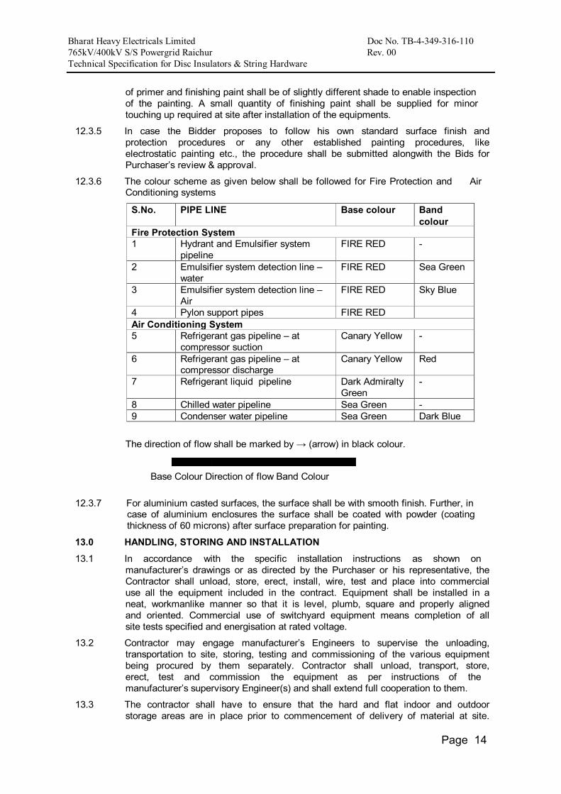
12.3.6 The colour scheme as given below shall be followed for Fire Protection and Air Conditioning systems
S.No. PIPE LINE Base colour Band colour
Fire Protection System 1 Hydrant and Emulsifier system
pipeline FIRE RED -
2 Emulsifier system detection line – water
FIRE RED Sea Green
3 Emulsifier system detection line – Air
FIRE RED Sky Blue
4 Pylon support pipes FIRE RED Air Conditioning System 5 Refrigerant gas pipeline – at
compressor suction Canary Yellow -
6 Refrigerant gas pipeline – at compressor discharge
Canary Yellow Red
7 Refrigerant liquid pipeline Dark Admiralty Green
-
8 Chilled water pipeline Sea Green - 9 Condenser water pipeline Sea Green Dark Blue
The direction of flow shall be marked by → (arrow) in black colour.
Base Colour Direction of flow Band Colour
12.3.7 For aluminium casted surfaces, the surface shall be with smooth finish. Further, in case of aluminium enclosures the surface shall be coated with powder (coating thickness of 60 microns) after surface preparation for painting.
13.0 HANDLING, STORING AND INSTALLATION
13.1 In accordance with the specific installation instructions as shown on manufacturer’s drawings or as directed by the Purchaser or his representative, the Contractor shall unload, store, erect, install, wire, test and place into commercial use all the equipment included in the contract. Equipment shall be installed in a neat, workmanlike manner so that it is level, plumb, square and properly aligned and oriented. Commercial use of switchyard equipment means completion of all site tests specified and energisation at rated voltage.
13.2 Contractor may engage manufacturer’s Engineers to supervise the unloading, transportation to site, storing, testing and commissioning of the various equipment being procured by them separately. Contractor shall unload, transport, store, erect, test and commission the equipment as per instructions of the manufacturer’s supervisory Engineer(s) and shall extend full cooperation to them.
13.3 The contractor shall have to ensure that the hard and flat indoor and outdoor storage areas are in place prior to commencement of delivery of material at site.

Bharat Heavy Electricals Limited Doc No. TB-4-349-316-110 765kV/400kV S/S Powergrid Raichur Rev. 00 Technical Specification for Disc Insulators & String Hardware
Page 15
Contractor shall also ensure availability of proper unloading and material handling equipment like cranes etc. and polyester/nylon ropes of suitable capacity to avoid damage during unloading and handling of material at site. All indoor equipments shall be stored indoors. Outdoor equipment may be stored outdoors but on a hard and flat raised area properly covered with waterproof and dustproof covers to protect them from water seepage and moisture ingress. However, all associated control panels, marshalling boxes operating boxes etc. of outdoor equipments are to be stored indoors only.
Storage of equipment on top of another one is not permitted if the wooden packing is used. Material opened for joint inspection shall be repacked properly as per manufacturer’s recommendations.
During storage of material regular periodic monitoring of important parameters like oil level / leakage, SF6 / Nitrogen pressure etc. shall be ensured by the contractor.
13.4 In case of any doubt/misunderstanding as to the correct interpretation of
manufacturer’s drawings or instructions, necessary clarifications shall be obtained from the Purchaser. Contractor shall be held responsible for any damage to the equipment consequent to not following manufacturer’s drawings/instructions correctly.
13.5 Where assemblies are supplied in more than one section, Contractor shall make all necessary mechanical and electrical connections between sections including the connection between buses. Contractor shall also do necessary adjustments/alignments necessary for proper operation of circuit breakers, isolators and their operating mechanisms. All components shall be protected against damage during unloading, transportation, storage, installation, testing and commissioning. Any equipment damaged due to negligence or carelessness or otherwise shall be replaced by the Contractor at his own expense.
13.6 Contractor shall be responsible for examining all the shipment and notify the Purchaser immediately of any damage, shortage, discrepancy etc. for the purpose of Purchaser’s information only. The Contractor shall submit to the Purchaser every week a report detailing all the receipts during the weeks. However, the Contractor shall be solely responsible for any shortages or damages in transit,
handling and/or in storage and erection of the equipment at Site. Any demurrage, wharfage and other such charges claimed by the transporters, railways etc. shall be to the account of the Contractor.
13.7 The Contractor shall be fully responsible for the equipment/material until the same is handed over to the Purchaser in an operating condition after commissioning. Contractor shall be responsible for the maintenance of the equipment/material while in storage as well as after erection until taken over by Purchaser, as well as protection of the same against theft, element of nature, corrosion, damages etc.
13.8 Where material / equipment is unloaded by Purchaser before the Contractor arrives at site or even when he is at site, Purchaser by right can hand over the same to Contractor and there upon it will be the responsibility of Contractor to store the material in an orderly and proper manner.
13.9 The Contractor shall be responsible for making suitable indoor storage facilities, to store all equipment which requires indoor storage.
13.10 The words ‘erection’ and ‘installation’ used in the specification are synonymous.
13.11 Exposed live parts shall be placed high enough above ground to meet the requirements of electrical and other statutory safety codes.
13.12 The design and workmanship shall be in accordance with the best engineering

Bharat Heavy Electricals Limited Doc No. TB-4-349-316-110 765kV/400kV S/S Powergrid Raichur Rev. 00 Technical Specification for Disc Insulators & String Hardware
Page 16
practices to ensure satisfactory performance throughout the service life. If at any stage during the execution of the Contract, it is observed that the erected equipment(s) do not meet the above minimum clearances as given in clause 4.7.1 the Contractor shall immediately proceed to correct the discrepancy at his risks and cost.
13.13 Equipment Bases
A cast iron or welded steel base plate shall be provided for all rotating equipment which is to be installed on a concrete base unless otherwise agreed to by the Purchaser. Each base plate shall support the unit and its drive assembly, shall be of a neat design with pads for anchoring the units, shall have a raised lip all around, and shall have threaded drain connections.
14.0 TOOLS AND TACKLES
The Contractor shall supply with the equipment one complete set of all special tools and tackles for the erection, assembly, dis-assembly and maintenance of the equipment. However, these tools and tackles shall be separately, packed and brought on to Site.
15.0 AUXILIARY SUPPLY
15.1 The sub-station auxiliary supply is normally met through a system indicated under section “Electrical & Mechanical Auxiliaries” having the following parameters. The auxiliary power for station supply, including the equipment drive, cooling system of any equipment, air-conditioning, lighting etc shall be designed for the specified Parameters as under. The DC supply for the instrumentation and PLCC system shall also conform the parameters as indicated in the following.
Normal Voltage
Variation in Voltage
Frequency in HZ
Phase/W ire
Neutral connection
415V + 10% 50 + 5% 3/4 Wire Solidly Earthed. 240V + 10% 50 + 5% 1/2 Wire Solidly Earthed. 220V 190V to 240V DC - Isolated 2 wire
System 110V 95V to 120V DC - Isolated 2 wire
System
48V _ DC _ 2 wire system (+) earthed
Combined variation of voltage and frequency shall be limited to + 10%.
16.0 SUPPORT STRUCTURE
16.1 The equipment support structures shall be suitable for equipment connections at the first level i.e 14.0 meter, 8.0 meter and 5.9 meter from plinth level for 765 kV, 420 kV and 245 kV substations respectively. All equipment support structures shall be supplied alongwith brackets, angles, stools etc. for attaching the operating mechanism, control cabinets & marshalling box (wherever applicable) etc.
16.2 Support structure shall meet the following mandatory requirements:
16.2.1 The minimum vertical distance from the bottom of the lowest porcelain part of the bushing, porcelain enclosures or supporting insulators to the bottom of the equipment base, where it rests on the foundation pad shall be 2.55 metres.
17.0 CLAMPS AND CONNECTORS INCLUDING TERMINAL CONNECTORS
17.1 All power clamps and connectors shall conform to IS:5561 & NEMA CC1 and shall be made of materials listed below :

Bharat Heavy Electricals Limited Doc No. TB-4-349-316-110 765kV/400kV S/S Powergrid Raichur Rev. 00 Technical Specification for Disc Insulators & String Hardware
Page 17
a) For connecting Aluminum alloy casting, ACSR conductors conforming to designation A6 of IS:617 and all test shall conform to IS:617 b) For connecting Bimetallic connectors made equipment ter- from aluminum alloy casting, minals made of conforming to designation A6 copper with of IS:617 with 2mm thick ACSR conductors bimetallic liner and all test shall conform to IS:617 c) For connecting G.I Galvanised mild steel shield wire
d) i) Bolts, nuts & i) Electrogalvanised for sizes
Plain, washers below M12, for others hot dip galvanised.
ii) Spring washers ii) Electro-galvanised mild for items steel suitable for atleast ‘a’ to ‘c’ service condition-3 as per
IS:1573
17.2 Necessary clamps and connectors shall be supplied for all equipment and connections. The requirement regarding external corona and RIV as specified for any equipment shall include its terminal fittings. If corona rings are required to meet these requirements they shall be considered as part of that equipment and included in the scope of work.
17.3 Where copper to aluminum connections are required, bi-metallic clamps shall be used, which shall be properly designed to ensure that any deterioration of the connection is kept to a minimum and restricted to parts which are not current carrying or subjected to stress.
17.4 Low voltage connectors, grounding connectors and accessories for grounding all equipment as specified in each particular case, are also included in the scope of Work.
17.5 No current carrying part of any clamp shall be less than 10 mm thick. All ferrous parts shall be hot dip galvanised. Copper alloy liner of minimum 2 mm thickness shall be cast integral with aluminum body or 2 mm thick bi-metallic strips shall be provided for Bi-metallic clamps.
17.6 All casting shall be free from blow holes, surface blisters, cracks and cavities. All sharp edges and corners shall be blurred and rounded off.
17.7 Flexible connectors, braids or laminated straps made for the terminal clamps for bus posts shall be suitable for both expansion or through (fixed/sliding) type connection of 4" IPS AL. tube as required. In both the cases the clamp height (top of the mounting pad to centre line of the tube) should be same.
17.8 Clamp shall be designed to carry the same current as the conductor and the temperature rise shall be equal or less than that of the conductor at the specified ambient temperature. The rated current for which the clamp/connector is designed with respect to the specified reference ambient temperature, shall also be indelibly marked on each component of the clamp/connector, except on the hardware.
17.9 All current carrying parts shall be designed and manufactured to have minimum contact resistance.
17.10 Clamps and connectors shall be designed to be corona controlled.
17.11 Tests

Bharat Heavy Electricals Limited Doc No. TB-4-349-316-110 765kV/400kV S/S Powergrid Raichur Rev. 00 Technical Specification for Disc Insulators & String Hardware
Page 18
17.11.1 Clamps and connectors should be type tested as per IS:5561 and shall also be subjected to routine tests as per IS:5561. Following type test reports shall be submitted for approval as per clause 9.2 above except for sl. no.(ii) & (iii) for which type test once conducted shall be applicable (i.e. the requirement of test conducted within last ten years shall not be applicable).
i) Temperature rise test (maximum temperature rise allowed is 35°C over 50°C ambient)
ii) Short time current test
iii) Corona (dry) and RIV (dry) test (for 220 KV and above voltage level clamps)
iv) Resistance test and tensile test
18.0 CONTROL CABINETS, JUNCTION BOXES, TERMINAL BOXES & MARSHALLING BOXES FOR OUTDOOR EQUIPMENT
18.1 All types of boxes, cabinets etc. shall generally conform to & be tested in accordance with IS-5039/IS-8623, IEC-60439, as applicable, and the clauses given below:
18.2 Control cabinets, junction boxes, Marshalling boxes & terminal boxes shall be made of sheet steel or aluminum enclosure and shall be dust, water and vermin proof. Sheet steel used shall be atleast 2.0 mm thick cold rolled or 2.5 mm hot rolled or alternately 1.6 mm thick stainless steel can also be used. The box shall be properly braced to prevent wobbling. There shall be sufficient reinforcement to provide level surfaces, resistance to vibrations and rigidity during transportation and installation. In case of aluminum enclosed box the thickness of aluminum shall be such that it provides adequate rigidity and long life as comparable with sheet steel of specified thickness.
18.3 A canopy and sealing arrangements for operating rods shall be provided in
marshalling boxes / Control cabinets to prevent ingress of rain water.
18.4 Cabinet/boxes shall be provided with double hinged doors with padlocking arrangements. The distance between two hinges shall be adequate to ensure uniform sealing pressure against atmosphere. The quality of the gasket shall be such that it does not get damaged/cracked during the operation of the equipment.
18.5 All doors, removable covers and plates shall be gasketed all around with suitably profiled EPDM/Neoprene gaskets. The gasket shall be tested in accordance with approved quality plan, IS:11149 and IS:3400. Ventilating Louvers, if provided, shall have screen and filters. The screen shall be fine wire mesh made of brass.
18.6 All boxes/cabinets shall be designed for the entry of cables from bottom by means of weather proof and dust-proof connections. Boxes and cabinets shall be designed with generous clearances to avoid interference between the wiring entering from below and any terminal blocks or accessories mounted within the box or cabinet. Suitable cable gland plate above the base of the marshalling kiosk/box shall be provided for this purpose along with the proper blanking plates. Necessary number of cable glands shall be supplied and fitted on this gland plate. Gland plate shall have provision for some future glands to be provided later, if required. The Nickel plated glands shall be dust proof, screw on & double compression type and made of brass. The gland shall have provision for securing armour of the cable separately and shall be provided with earthing tag. The glands shall conform to BS:6121.
18.7 A 240V, single phase, 50 Hz, 15 amp AC plug and socket shall be provided in the cabinet with ON-OFF switch for connection of hand lamps. Plug and socket shall be of industrial grade.

Bharat Heavy Electricals Limited Doc No. TB-4-349-316-110 765kV/400kV S/S Powergrid Raichur Rev. 00 Technical Specification for Disc Insulators & String Hardware
Page 19
18.8 For illumination, a fluorescent tube or CFL of approximately 9 to 15 watts shall be provided. The switching of the fittings shall be controlled by the door switch. .
For junction boxes of smaller sizes such as lighting junction box, manual operated earth switch mechanism box etc., plug socket, heater and illumination is not required to be provided.
18.9 All control switches shall be of MCB/rotary switch type and Toggle/piano switches shall not be accepted.
18.10 Positive earthing of the cabinet shall be ensured by providing two separate earthing pads. The earth wire shall be terminated on to the earthing pad and secured by the use of self etching washer. Earthing of hinged door shall be done by using a separate earth wire.
18.11 The bay marshalling kiosks shall be provided with danger plate and a diagram showing the numbering/connection/feruling by pasting the same on the inside of the door.
18.12 a) The following routine tests alongwith the routine tests as per IS:5039 shall also be conducted:
i) Check for wiring
ii) Visual and dimension check
b) The enclosure of bay marshalling kiosk, junction box, terminal box shall conform to IP-55 as per IS:13947 including application of, 2.5 KV rms for 1 (one) minute, insulation resistance and functional test after IP-55 test.
19.0 Deleted.
20.0 TERMINAL BLOCKS AND WIRING 20.1 Control and instrument leads from the switchboards or from other equipment will
be brought to terminal boxes or control cabinets in conduits. All interphase and external connections to equipment or to control cubicles will be made through terminal blocks.
20.2 Terminal blocks shall be 650V grade and have continuous rating to carry the maximum expected current on the terminals and non breakable type. These shall be of moulded piece, complete with insulated barriers, stud type terminals, washers, nuts and lock nuts. Screw clamp, overall insulated, insertion type, rail mounted terminals can be used in place of stud type terminals. But preferably the terminal blocks shall be non-disconnecting stud type of Elmex or Phoenix or Wago or equivalent make.
20.3 Terminal blocks for current transformer and voltage transformer secondary leads shall be provided with test links and isolating facilities. The current transformer secondary leads shall also be provided with short circuiting and earthing facilities.
20.4 The terminal shall be such that maximum contact area is achieved when a cable is terminated. The terminal shall have a locking characteristic to prevent cable from escaping from the terminal clamp unless it is done intentionally.
20.5 The conducting part in contact with cable shall preferably be tinned or silver plated however Nickel plated copper or zinc plated steel shall also be acceptable.
20.6 The terminal blocks shall be of extensible design.
20.7 The terminal blocks shall have locking arrangement to prevent its escape from the mounting rails.
20.8 The terminal blocks shall be fully enclosed with removable covers of transparent, non-deteriorating type plastic material. Insulating barriers shall be provided between the terminal blocks. These barriers shall not hinder the operator from carrying out the wiring without removing the barriers.

Bharat Heavy Electricals Limited Doc No. TB-4-349-316-110 765kV/400kV S/S Powergrid Raichur Rev. 00 Technical Specification for Disc Insulators & String Hardware
Page 20
20.9 Unless otherwise specified terminal blocks shall be suitable for connecting the following conductors on each side.
a) All circuits except Minimum of two of 2.5 sq mm
CT/PT circuits copper flexible. b) All CT/PT circuits Minimum of 4 nos. of 2.5 sq mm
copper flexible.
20.10 The arrangements shall be in such a manner so that it is possible to safely connect or disconnect terminals on live circuits and replace fuse links when the cabinet is live.
20.11 Atleast 20 % spare terminals shall be provided on each panel/cubicle/box and these spare terminals shall be uniformly distributed on all terminals rows.
20.12 There shall be a minimum clearance of 250 mm between the First/bottom row of terminal block and the associated cable gland plate for outdoor ground mounted marshalling box and the clearance between two rows of terminal blocks shall be a minimum of 150 mm.
20.13 The Contractor shall furnish all wire, conduits and terminals for the necessary interphase electrical connections (where applicable) as well as between phases and common terminal boxes or control cabinets. For equipments rated for 400 kV and above the wiring required in these items shall be run in metallic ducts or shielded cables in order to avoid surge overvoltages either transferred through the equipment or due to transients induced from the EHV circuits.
20.14 All input and output terminals of each control cubicle shall be tested for surge withstand capability in accordance with the relevant IEC Publications, in both longitudinal and transverse modes. The Contractor shall also provide all necessary filtering, surge protection, interface relays and any other measures necessary to achieve an impulse withstand level at the cable interfaces of the equipment.
21.0 LAMPS & SOCKETS
21.1 Sockets
All sockets (convenience outlets) shall be suitable to accept both 5 Amp & 15 Amp pin round Standard Indian plugs. They shall be switched sockets with shutters.
21.2 Hand Lamp:
A 240 Volts, single Phase, 50 Hz AC plug point shall be provided in the interior of each cubicle with ON-OFF Switch for connection of hand lamps.
21.3 Switches and Fuses:
21.3.1 Each panel shall be provided with necessary arrangements for receiving, distributing, isolating and fusing of DC and AC supplies for various control, signalling, lighting and space heater circuits. The incoming and sub-circuits shall be separately provided with miniature circuit breaker / switchfuse units. Selection of the main and Sub-circuit fuse ratings shall be such as to ensure selective clearance of sub-circuit faults. Potential circuits for relaying and metering shall be protected by HRC fuses.
21.3.2 All fuses shall be of HRC cartridge type conforming to IS:9228 mounted on plug-in type fuse bases. Miniature circuit breakers with thermal protection and alarm contacts will also be accepted. All accessible live connection to fuse bases shall be adequately shrouded. Fuses shall have operation indicators for indicating blown fuse condition. Fuse carrier base shall have imprints of the fuse rating and voltage.

Bharat Heavy Electricals Limited Doc No. TB-4-349-316-110 765kV/400kV S/S Powergrid Raichur Rev. 00 Technical Specification for Disc Insulators & String Hardware
Page 21
22.0 Bushings, Hollow Column Insulators, Support Insulators:
22.1 Bushings shall be manufactured and tested in accordance with IS:2099 & IEC- 60137 while hollow column insulators shall be manufactured and tested in accordance with IEC-62155/IS:5621.The support insulators shall be manufactured and tested as per IS:2544/IEC-60168 and IEC-60273. The insulators shall also conform to IEC-60815 as applicable.
The bidder may also offer composite hollow insulators, conforming to IEC-61462.
22.2 Support insulators, bushings and hollow column insulators shall be manufactured from high quality porcelain. Porcelain used shall be homogeneous, free from laminations, cavities and other flaws or imperfections that might affect the mechanical or dielectric quality and shall be thoroughly vitrified tough and impervious to moisture.
22.3 Glazing of the porcelain shall be uniform brown in colour, free from blisters, burrs and similar other defects.
22.4 Support insulators/bushings/hollow column insulators shall be designed to have ample insulation, mechanical strength and rigidity for the conditions under which they will be used.
22.5 When operating at normal rated voltage there shall be no electric discharge between the conductors and bushing which would cause corrosion or injury to conductors, insulators or supports by the formation of substances produced by
chemical action. No radio interference shall be caused by the insulators/bushings when operating at the normal rated voltage.
22.6 Bushing porcelain shall be robust and capable of withstanding the internal pressures likely to occur in service. The design and location of clamps and the shape and the strength of the porcelain flange securing the bushing to the tank shall be such that there is no risk of fracture. All portions of the assembled porcelain enclosures and supports other than gaskets, which may in any way be exposed to the atmosphere shall be composed of completely non hygroscopic material such as metal or glazed porcelain.
22.7 All iron parts shall be hot dip galvanised and all joints shall be air tight. Surface of joints shall be trued up porcelain parts by grinding and metal parts by machining. Insulator/bushing design shall be such as to ensure a uniform compressive pressure on the joints.
22.8 Tests
In bushing, hollow column insulators and support insulators shall conform to type tests and shall be subjected to routine tests in accordance with IS: 2099 & IS: 2544 & IS : 5621.
23.0 MOTORS
Motors shall be “Squirrel Cage” three phase induction motors of sufficient size capable of satisfactory operation for the application and duty as required for the driven equipment and shall be subjected to routine tests as per applicable standards. The motors shall be of approved make.
23.1 Enclosures
a) Motors to be installed outdoor without enclosure shall have hose proof enclosure equivalent to IP-55 as per IS: 4691. For motors to be installed indoor i.e. inside a box, the motor enclosure, shall be dust proof equivalent to IP-44 as per IS: 4691.

Bharat Heavy Electricals Limited Doc No. TB-4-349-316-110 765kV/400kV S/S Powergrid Raichur Rev. 00 Technical Specification for Disc Insulators & String Hardware
Page 22
b) Two independent earthing points shall be provided on opposite sides of the motor for bolted connection of earthing conductor.
c) Motors shall have drain plugs so located that they will drain water resulting from condensation or other causes from all pockets in the motor casing.
d) Motors weighing more than 25 Kg. shall be provided with eyebolts, lugs or other means to facilitate lifting.
23.2 Operational Features
a) Continuous motor rating (name plate rating) shall be at least ten (10) percent above the maximum load demand of the driven equipment at design duty point and the motor shall not be over loaded at any operating point of driven equipment that will rise in service.
b) Motor shall be capable at giving rated output without reduction in the expected life span when operated continuously in the system having the particulars as given in Clause 15.0 of this Section.
23.3 Starting Requirements:
a) All induction motors shall be suitable for full voltage direct-on-line starting. These shall be capable of starting and accelerating to the rated speed alongwith the driven equipment without exceeding the acceptable winding temperature even when the supply voltage drops down to 80% of the rated voltage.
b) Motors shall be capable of withstanding the electrodynamic stresses and heating imposed if it is started at a voltage of 110% of the rated value.
c) The locked rotor current shall not exceed six (6) times the rated full load current for all motors, subject to tolerance as given in IS:325.
d) Motors when started with the driven equipment imposing full starting torque under the supply voltage conditions specified under Clause 15.0 shall be capable of withstanding atleast two successive starts from cold condition at room temperature and one start from hot condition without injurious heating of winding. The motors shall also be suitable for three equally spread starts per hour under the above referred supply condition.
e) The locked rotor withstand time under hot condition at 110% of rated voltage shall be more than starting time with the driven equipment of minimum permissible voltage by at least two seconds or 15% of the accelerating time whichever is greater. In case it is not possible to meet the above requirement, the Bidder shall offer centrifugal type speed switch mounted on the motor shaft which shall remain closed for speed lower than 20% and open for speeds above 20% of the rated speed. The speed switch shall be capable of withstanding 120% of the rated speed in either direction of rotation.
23.4 Running Requirements:
a) The maximum permissible temperature rise over the ambient temperature of 50 degree C shall be within the limits specified in IS:325 (for 3 - phase induction motors) after adjustment due to increased ambient temperature specified.
b) The double amplitude of motor vibration shall be within the limits specified in IS: 4729. Vibration shall also be within the limits specified by the relevant standard for the driven equipment when measured at the motor bearings.
c) All the induction motors shall be capable of running at 80% of rated voltage for a period of 5 minutes with rated load commencing from hot condition.

Bharat Heavy Electricals Limited Doc No. TB-4-349-316-110 765kV/400kV S/S Powergrid Raichur Rev. 00 Technical Specification for Disc Insulators & String Hardware
Page 23
23.5 TESTING AND COMMISSIONING
An indicative list of tests is given below. Contractor shall perform any additional test based on specialities of the items as per the field Q.P./Instructions of the equipment Contractor or Purchaser without any extra cost to the Purchaser. The Contractor shall arrange all instruments required for conducting these tests alongwith calibration certificates and shall furnish the list of instruments to the Purchaser for approval.
(a) Insulation resistance.
(b) Phase sequence and proper direction of rotation.
(c) Any motor operating incorrectly shall be checked to determine the cause and the conditions corrected.
ANNEXURE-A
CORONA AND RADIO INTERFERENCE VOLTAGE (RIV) TEST
1. General
Unless otherwise stipulated, all equipment together with its associated connectors, where applicable, shall be tested for external corona (for 400kV & above) both by observing the voltage level for the extinction of visible corona under falling power frequency voltage and by measurement of radio interference voltage (RIV) for 132kV above.
2. Test Levels:
The test voltage levels for measurement of external RIV and for corona extinction voltage are listed under the relevant clauses of the specification.
3. Test Methods for RIV:
3.1 RIV tests shall be made according to measuring circuit as per International
Special-Committee on Radio Interference (CISPR) Publication 16-1(1993) Part -1. The measuring circuit shall preferably be tuned to frequency with 10% of 0.5 Mhz but other frequencies in the range of 0.5 MHz to 2 MHz may be used, the measuring frequency being recorded. The results shall be in microvolts.
3.2 Alternatively, RIV tests shall be in accordance with NEMA standard Publication
No. 107-1964, except otherwise noted herein.
3.3 In measurement of, RIV, temporary additional external corona shielding may be

Bharat Heavy Electricals Limited Doc No. TB-4-349-316-110 765kV/400kV S/S Powergrid Raichur Rev. 00 Technical Specification for Disc Insulators & String Hardware
Page 24
provided. In measurements of RIV only standard fittings of identical type supplied with the equipment and a simulation of the connections as used in the actual installation will be permitted in the vicinity within 3.5 meters of terminals.
3.4 Ambient noise shall be measured before and after each series of tests to ensure
that there is no variation in ambient noise level. If variation is present, the lowest ambient noise level will form basis for the measurements. RIV levels shall be measured at increasing and decreasing voltages of 85%, 100%, and 110% of the specified RIV test voltage for all equipment unless otherwise specified. The specified RIV test voltage for 765kV, 400 kV, 220 KV is listed in the detailed specification together with maximum permissible RIV level in microvolts.
3.5 The metering instruments shall be as per CISPR recommendation or equivalent
device so long as it has been used by other testing authorities.
3.6 The RIV measurement may be made with a noise meter. A calibration procedure of the frequency to which noise meter shall be tuned shall establish the ratio of voltage at the high voltage terminal to voltage read by noisel meter.
4. Test Methods for Visible Corona
The purpose of this test is to determine the corona extinction voltage of apparatus, connectors etc. The test shall be carried out in the same manner as RIV test described above with the exception that RIV measurements are not required during test and a search technique shall be used near the onset and extinction voltage, when the test voltage is raised and lowered to determine their precise values. The test voltage shall be raised to 110% of specified corona extinction voltage and maintained there for five minutes. In case corona inception does not take place at 110%, test shall be stopped, otherwise test shall be continued and the voltage will then be decreased slowly until all visible corona disappears. The procedure shall be repeated at least 4 times with corona inception and extinction voltage recorded each time. The corona extinction voltage for purposes of determining compliance with the specification shall be the lowest of the four values at which visible corona (negative or positive polarity) disappears. Photographs with laboratory in complete darkness shall be taken under test conditions, at all voltage steps i.e. 85%, 100%, and 110%. Additional photographs shall be taken at corona inception and extinction voltages. At least two views shall be photographed in each case using Panchromatic film with an ASA daylight rating of 400 with an exposure of two minutes at a lens aperture of f/5.6 or equivalent. The photographic process shall be such that prints are available for inspection and comparison with conditions as determined from direct observation. Photographs shall be taken from above and below the level of connector so as to show corona on bushing, insulators and all parts of energised connectors. The photographs shall be framed such that test object essentially, fills the frame with no cut-off.
For recording purpose, modern devices utilizing UV recording methods such as image intensifier may also be used.
4.1 The test shall be recorded on each photograph. Additional photograph shall be
taken from each camera position with lights on to show the relative position of test object to facilitate precise corona location from the photographic evidence.
4.2 In addition to photographs of the test object preferably four photographs shall be
taken of the complete test assembly showing relative positions of all the test equipment and test objects. These four photographs shall be taken from four

Bharat Heavy Electricals Limited Doc No. TB-4-349-316-110 765kV/400kV S/S Powergrid Raichur Rev. 00 Technical Specification for Disc Insulators & String Hardware
Page 25
points equally spaced around the test arrangement to show its features from all sides. Drawings of the laboratory and test set up locations shall be provided to indicate camera positions and angles. The precise location of camera shall be approved by Purchaser’s inspector, after determining the best camera locations by trial energisation of test object at a voltage which results in corona.
4.3 The test to determine the visible corona extinction voltage need not be carried out
simultaneously with test to determine RIV levels.
4.4 However, both test shall be carried out with the same test set up and as little time duration between tests as possible. No modification on treatment of the sample between tests will be allowed. Simultaneous RIV and visible corona extinction voltage testing may be permitted at the discretion of Purchaser’s inspector if, in his opinion, it will not prejudice other test.
5. Test Records:
In addition to the information previously mentioned and the requirements specified as per CISPR or NEMA 107-1964 the following data shall be included in test report:
a) Background noise before and after test.
b) Detailed procedure of application of test voltage.
c) Measurements of RIV levels expressed in micro volts at each level.
d) Results and observations with regard to location and type of interference sources detected at each step.
e) Test voltage shall be recorded when measured RIV passes through 100 microvolts in each direction.
f) Onset and extinction of visual corona for each of the four tests required shall be recorded.
The seismic withstanding test on the complete equipment (for 132kV and above) shall be carried out alongwith supporting structure.
The Bidder shall arrange to transport the structure from his Contractor’s premises/POWERGRID sites for the purpose of seismic withstand test only.
The seismic level specified shall be applied at the base of the structure. The accelerometers shall be provided at the Terminal Pad of the equipment and any other point as agreed by the Purchaser. The seismic test shall be carried out in all possible combinations of the equipment. The seismic test procedure shall be furnished for approval of the Purchaser.

Bharat Heavy Electricals Limited Doc No. TB-4-349-316-110 765kV/400kV S/S Powergrid Raichur Rev. 00 Technical Specification for Disc Insulators & String Hardwares
GUARANTEED TECHNICAL PARTICULARS FOR DISC INSULATORS
Sl. No.
Particulars Unit 765kV Double Tension Insulator
String
765kV Single Suspension
Insulator String
400kV Double Tension Insulator
String
400kV Single Suspension
Insulator String
1. Manufacturer’s Name & address
2. Type of String : a) Single / Double b) Suspension/ Tension
3. Applicable Standards
4. Type of Insulators : a) Ball & Socket / Other b) Normal / Anti Fog
5. Insulation Material
6. No. of units per string
7. Size of each unit :- a) Diameter of Disc b) Spacing between adjacent units
Mm mm
8. Weight (Approx.) a) Each Disc b) Complete String (Insulator Only)
Kg Kg
9. Total Creepage distance a) Each Disc b) Complete String ( Insulators only)
Mm Mm
10. Power frequency withstand voltage a) Each Disc i) Dry ii) Wet b) Complete String i) Dry ii) Wet
kV kV
kV kV
11. Impulsive withstand voltage a) Each Disc i) Positive ii) Negative b) Complete String i) Positive ii) Negative
kVp kVp
kVp kVp

Bharat Heavy Electricals Limited Doc No. TB-4-349-316-110 765kV/400kV S/S Powergrid Raichur Rev. 00 Technical Specification for Disc Insulators & String Hardwares
12. Switching Surge
withstand voltage a) Positive b) Negative
kVp kVp
13. Power frequency puncture withstand voltage of each disc
kV
14. Min. corona extinction voltage level : a) Each disc b) Complete String
kV kV
15. RIV level with corona control rings at 305kV (rms)for 400kV string at 1 MHz.
µV
16. Electrochemical strength : a) Each Disc b) Complete String
kN kN
17. Reference Drawing
18. Magnetic power loss of suspension and drop clamp assembly at 600 A
W

765kV/400kV S/s Raichur Substation (New),under system Strengthening in SR & WR for Krishnapatnam UMPP-Part-B Bharat Heavy Electricals Ltd. Doc. No. TB-349-316-108 Rev. No. 00 Technical Specification AC & DC BOARD
_____________________________________________________________________________________________________ Page 1 of 1
ANNEXURE - A SCHEDULE OF TECHNICAL DEVIATIONS
Bidder shall list below all technical deviation clause wise w.r.t. tender specifications: S.No. Page No. Clause No. Deviation Reason / Justification Any deviation not specifically brought out in this section shall not be admissible for any commercial implication at later stage. Except to the technical deviations listed in this schedule, bidder’s offer shall be considered in full compliance to the tender specifications irrespective of any such deviation indicated / taken elsewhere in the submitted offer.
Date: Tenderer’s Stamp & Signature