7zegeneral radio .-vnh-- - iet labs · 7zegeneral radio ew ... ux-120 cx-220 3.3 ux-10ia cx-30ia...
TRANSCRIPT
IET LABS, Inc in the GenRad tradition
534 Main Street, Westbury, NY 11590 www.ietlabs.com
TEL: (516) 334-5959 • (800) 899-8438 • FAX: (516) 334-5988
7zeGENERAL RADIO
ew
An old Arabian legend tells how Aladdin, seeking to recover his magic but unpretentiousappearing lamp which had been unwittingly discarded by a servant, went to the market place, where he astonished the populace by offering to give away new lamps for old. In a like manner a modern Aladdin might offer to give new lamps (vacuum tubes) in exchange for old without deserving much credit as a philanthropist. All of which introduces us to the subject of the reactivation of vacuum tubes by the simple process of rejuvenating their filaments.
< oE th cuum t used in radio reception today have the so-called thoriated filaments. Chief among these are the Radiotrons: UV and UX-199, UX-120, UX-200-A, UX-20 I-A, UX-17l, UX-210, UX-213 and UX-216-B; the Cunningham tubes: C and CX-299, CX-120, CX-300-A, CX-301-A, CX-371, CX-310, CX-313 and CX-316-B; and corresponding tubes from other manufacturers.
The electronic emission of these tubes, that is, their plate current, depends upon the presence of a layer of thorium atoms on the outer surface of the filament. The filament is not thorium-coated, however, after the manner of the oxide-coated filaments, but is, rather, permeated throughout its whole substance with this rare element, thorium. During the normal operation of these tubes the thorium on the outer surface of
.-.....vNh--
d Engineering Department
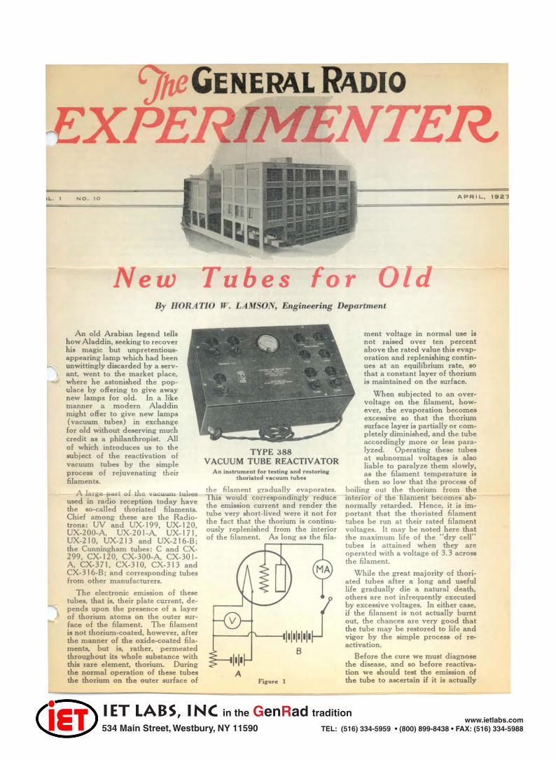
TYPE 388 VACUUM TUBE REACTIVATOR
An instrument fo r l eating and reltori nl' thoriated vacuum lubea
the filament gradually evaporates. This would correspondingly reduce the emission current and render the tube very short-lived were it not for the fact that the thorium is continuously replenished from the interior of the filament. As long as the fila-
A Fil'ure 1
ment voltage in normal use is not raised over ten percent above the rated value this evaporation and replenishing continues at an equilibrium rate, so that a constant layer of thorium is maintained on the surface.
When subjected to an overvoltage on the filament, however, the evaporation becomes excessive so that the thorium surface layer is partially or completely diminished, and the tube accordingly more or less para-lyzed. Operating these tubes at subnormal voltages is also liable to paralyze them slowly, as the filament temperature is then so low that the process of
boiling out the thorium from the interior of the filament becomes abnormally retarded. Hence, it is important that the thoriated filament tubes be run at their rated filament voltages. It may be noted here that the maximum life of the "dry cell" tubes is attained when they are operated with a voltage of 3.3 across the filament.
While the great majority of thoriated tubes after a long and useful life gradually die a natural death, others are not infrequently executed by excessive voltages. In either case, if the filament is not actually burnt out, the chances are very good that the tube may be restored to life and vigor by the simple process of reactivation.
Before the cure we must diagnose the disease, and so before reactivation we should test the emission of the tube to ascertain if it is actually

IET LABS, Inc in the GenRad tradition
534 Main Street, Westbury, NY 11590 www.ietlabs.com
TEL: (516) 334-5959 • (800) 899-8438 • FAX: (516) 334-5988
IHE I I'
T",e of Tube Fit. Plate Min.
E.M.F. E.M. F. £mi .. ioD UV-199 UX-199
C-299 CX-299 3.3 50 6 m. a. --- ----
UX-120 CX-220 3.3
UX-10IA CX-30IA 5.0
UX-200A CX-300A 5.0
UX-171 ex·371 5.0
UX-210 C ·310 6.0
UX-213 CX-313 4.0
UX-216B CX·316B 6.0
below normal. To do this the circuit shown in Figure I is used. The grid and plate are tied directly together and then joined to the plus terminal of the B battery through a milliammeter. The negative B battery terminal is joined to the negative end of the filament and a key switch, normally open, is included in the plate circuit. The voltage across the filament, read on " V ," should first be adjusted to the values specified in the table, which give also the proper values of B battery to use with the different tubes. These values should not be exceeded. Now depress the key just long enough to obtain a reading of the emission current on MA. (Disregard the change in voltmeter reading caused by the emission current.) II the emission current obtained under these condi· tions is zero, or any value less than the minimum specified in the table. the tube can doubtless be improved by reactivation . These values and the recommended voltages were taken from literature furnished by E. T . Cunningham, Incorporated.
Reactivation can advantageously be accomplished in two steps : the first known as "flashing" and the second as "cooking." In both of these processes the grid and plate of the tube should be completely disconnected from any external circuits.
For flashing three-volt tubes, a voltage of twelve is applied to the filam ent for a period of about one second. This will completely paralyze the tube as the surface layer of thorium is wholly evaporated, but the " boiling-out" process within the filament is expedited by the flashing to such a degree that, if the tube is now cooked with a voltage of four across the filament, the surface layer will be rapidly replaced, so that, in a few moments, the emission of the filament will come back to normal and the rejuvenated tube is ready for another long lease of life. A constant " cooking voltage" of four is permis· sible in this case because there is no
50 15m. a.
50 25 m. a.
50 12 m. a.
50 50 m. a .
100 100m.a.
100 50 per anode
125 100
em ission current to expedite surface evaporation.
If a subsequent emission test shows that the filament failed to respond to this reactivation process it is evi· dent that the tube has served its normal life or else has been so heavily overloaded that the vacuum has been impaired.
The five-volt tubes should be Bashed for the same interval at eighteen volts on the filament and cooked at seven volts. Flashing is n ot recommended for the power amplifiers UX-21 0 or CX-31 O. or the rectifier tubes UX-213, CX-313. UX-216-B and CX·316·B. The e tubes may. however, be reactivated merely by cooking them for longer intervals. The UX-213 or CX·313 at six volts and the others at nine volts on the filament.
40
3D 8 ) V I A, /"
"" II .32 I ~ I'-.
28 I" I / ........
.. If 24 I ~
I ~ I CO
Id "-
If
IG I ~ I) I ~ 12 ~
4~1~/ +-~~+4~4-~~
011' 1 2 .3
Figure 2
Curve A in Figure 2 shows the customary normal recovery of a UX-20 I-A tube while cooking at seven volts, after being Hashed at eighteen volts. This recovery is slow at first, then increases rapidly,
,1:.1\
and finally slows down again as a saturation value is reached. When the tube was flashed at eighteen volts and then cooked at its rated filament voltage (five volts) , the same saturation current was finally attained. but only after thirty-five minutes of cooking. Likewise recovery to the same saturation current. when cooked with four volts on the filament. required a period of two and one-half hours. On the other hand. cooking at nine volts on the filament caused a prompt recovery, but the saturation current was subsequently reduced, as shown in curve B, since, in this case, evaporation from the surface (even with no emission current) exceeded the boiling-out of thorium from the interior.
Curve C shows the recovery of the 20 I-A tube flashed at twelve volts and cooked at seven volts. The rate of recovery and final saturation values are seen to be slightly less than curve B, where the same tube was Rashed at eighteen volts. It should be stated that the data for curve C were actually taken before the data for curve B, so that the results cannot be explained by a deterioration of the tube. Thus it is apparent that the recommended voltages for Hashing and cooking should be used to secure best resul ts.
It was found that tubes could. on the average, be Bashed and recovered ix or eight times before showing any decrease in the saturation current, which would indicate a de· terioration of the filament. This deteriora tion, however, was not rapid, a dozen flashings serving to reduce the saturation current by only 8 or 10 percent. This does not mean, however, that the total life of a thoriated filament properly used may be increased tenfold by reactivation. Reactivation might be expected, perhaps, to triple the useful life of the tube.
Realizing the value to the experimenter and the dealer of a simple device for testing and reactivating tubes, the General Radio Company has developed the Type 388 Tube Reactivator which operates from I 10-volt, 60-cycle A. C. No battcries or other equipment are necessary to the operation of this instrument. Sockets are provided whereby the correct voltage for testing, BashiJlg, and "cooking" are automatically obtained without any adjustments whatever. The operation is, accord· ingly, extremely simple and the results quite satisfactory. The emission of the various oxide-coated filaments can likewise be tested on the Type 388 Tube Reactivator, but these tubes can not. of course, be leactivated .
..

IET LABS, Inc in the GenRad tradition
534 Main Street, Westbury, NY 11590 www.ietlabs.com
TEL: (516) 334-5959 • (800) 899-8438 • FAX: (516) 334-5988
The Typ e 413 Beat · Frequency Oscillator
In!measuring loudspeakers and audio frequency systems, it is often desirable to move through the entire frequency range quickly. The convention .... 1 t ype uPvacuum tub-e oscillator although it may be 50 designed a to be continuously variable, requires the adjustment of a number of controls in varying the frequency through the entire audio range. As the change in frequency involved is large. about five hundred to one. it cannot be ob· tained by the rotation of a ingle in· strument o f practicable construction. If the measuring frequency is obtained by beating two oscillators together, a small percentage change in frequency of one of the oscillators will cause a relatively large change in the beat frequency.
Supplementing its oscillators of conventional type, the General Radio Company is manufacturing a beat frequency oscillator for the audio frequency range. The Type 413 BeatFrequency Oscillator consists of two oscillators, a detector, and an ampli. fier tube. The frequency of one of the oscillators is fixed at about 60 kilocycles. while that of the other is variable from approximately 50 to 60 K. C. Both oscillators are coupled to the grid circuit of the detector tube. The oscillators are so constructed and shielded as to maintain a constant frequency over long periods without adjustment. The system of coupling the oscillators to the detector. supplying it with a low voltage from each
scillator is su enc of the
two oscillators to pull into synchronism as zero beat is approached is eliminated. The detector output is fed through a Type 373 impedance l:oupier giving-nearly-corrstant amplification over the wide range of Frequencies used. to an amplifier tube. The output of the oscillator is taken off across a 10,000 ohm resistor used as a voltage divider, permitting the adjustment of the output voltage without changes in the oscillator circuit proper which might affect wave-form or frequency.
Three variable capacities will be een in the diagram. One of these
is a small compensating condenser mounted inside the instrument. The purpose of this condenser is to correct for any slight inaccuracy in the fixed condenser in this circuit. The Frequency is changed by means of two other variable condensers. the main tuning unit of 500 MMF maximum capacity, and a micro - condenser shunted across it for fine adjustment.
The Beat-Frequency Oscillator is designed for use with either WX- 12 or UX- 199 tubes, space being provided in the cabinet for three one and one-half volt dry cells and three twenty-two volt .. B" batteries. UX-20 I A tubes may be used with an external battery if desired. A five-volt Weston meter on the panel. and a rheostat inside the cabinet permit the adjustment of the filament voltage to the rated value. The Type 413 os· cillator has an output of about two and one-half volts. The variation in output voltage over the frequency range is slightly less than 10%. The wave-form is satisfactory for most purposes. the total of harmonics being at a maximum less than 4 % of the wave in voltage.
The Type 413 oscillator is useful in the measurement of all devices intended for operation in the audio frequency range. It is particularly helpful in the study of loudspeaker response curves, as the complete frequency range at practically constant intensity is available by one half revolution of the main dial so that peaks or hollows in the response of the speaker are immediately evident. Any tendency to blast at particular fre~encies is quickly revealed.
The instrument is licensed under Patent No. I, I 1 3, 149 by the Radio Corporation of America for experimental laboratory use only where no commercial features are involved.
The price of the Type 4 1 3 BeatFrequency Oscillator, without tubes and batteries is $210.
Matching Impedance When two elements in an elec
trical system are connected together, the efficiency of the system depends to a large degree on the relations existing between the impedances of the units coupled together, and some form of "adjusting" transformer is required. Questions asked in recent correspondence would seem to indicate that there is some confusion as to the pIinciple of such devices_
The design of the coupling device depends on whether it is desired to transfer the maximum of voltage, current, or power, to the receiving unit. In the conventional vacuum tube amplifier. the object is to obtain as high a voltage as possible in the grid of the succeeding tube. The load on the coupling device is practically an open circuit. In this case, the object is to obtain as high an input impedance in the coupling device as possible. As the transformer operates with its secondary practically open circuited, the primary impedance with secondary open circuited is a true indication of whether or not the device is suited for a given use.
There are many cases where it is required to get a maximum transfer of power occurs when the impedance of the receiving circuit equals that of the source. It is frequently necessary to use a transformer to obtain this optimum transfer in places where the source and load are of widely differing impedances. There seems to be a widesprea misunaerstanding of the function of transformer in this case. Frequently orders are received for a transformer to have "10,000 ohms primary impedance, 5,000 ohms secondary impedance." What is wanted is a transformer suitable for use between impedances of 10,000 and 5,000 ohms. A transformer having open circuit impedances as specified would be entirely unsuited to this use. The transformer is not "matched" to the load impedances. its function is to match the load impedances to each other. The object is not to get the maximum power into the transformer, but to get it into the load. For this purpose the impedance ratio, not the actual impedance is the important factor. The actual open circuit impedance is of importance, since it forms a load in parallel with the useful load, If a transformer with a 10.000 ohm primary were supplied for working out
--~----'

IET LABS, Inc in the GenRad tradition
534 Main Street, Westbury, NY 11590 www.ietlabs.com
TEL: (516) 334-5959 • (800) 899-8438 • FAX: (516) 334-5988
of a 10,000 ohm source, half of the available power would be lost in the transformer. The open circuit impedance must be several times the impedance of the loads being coupled together for an efficient transfer. A transformer, for example, for coupling a 10,000 ohm tube impedance to a reproducer should have 50,000 ohms or more, open circuit primary impedance.
What Speaker? Frequently we are asked the ques
tion: • 'What speaker do you recommend for me to use?" or "Should I buy the -- speaked" This is one of those questions like: "Have you stopped beating your wife?" which cannot be answered directly without embarrassment. Leaving out of the question the fact that tastes differ to the extent that a speaker, which is shown by every test to be an acoustical atrocity, will have its enthusiastic admirers, while a high quality reproduction is condemned as "boxy" or "muffled," the answer is not simple, because the behavior of a speaker depends to a great extent on the amplifier with which it is used. It might be thought that the effect of the speaker and amplifier are directly additive, that a good speaker will sound better even on a poor amplifier than an inferior speaker. Such does not prove to be the case. Some speakers are, of course. so bad that they are terrible with any amplifier. Between a great many speakers, however, the amplifier will determine the choice. A perfect amplifier would, of course, sound best with a perfect speaker, and, as a rule, the better the amplifier, the better the speaker which will give best results. This can be very readily observed by means of an interesting experiment which does not require a great deal of apparatus. A simple filter is connected between the output of a high quality amplifier and a quick throw switch by means of which the speakers are to be compared. The inductance coil of the filter should be so constructed that it is possible to move the iron core in and out changing the cut-off frequency of the filter. With the filter removed, tune in a station having a high quality output and classify the speakers under lest in order. If the amplifier and broadcast are of good quality, this test will probably give results indicative of the actual merit of the speakers per se. This is not always the case, as the type of music received also affects the result. As the iron in the filter is moved in and out, cutting out different parts of the frequency range, it will be found that first one
and then another of the speakers will be selected as giving the most pleasing effect.
If you live in a large city, where there are a number of broadcast stations, the filter will be unnecessary,
simply turn to stations of varying degrees of perfect or imperfect output.
Beauty. it is said. is in the eye of the beholder, so quality lies in the ear of the auditor-and lies and lies.
An Instrume1J.t for Making Graphic Record of Signal Streng th Variation
Among the many scientific instruments made by the General Radio Company is the Type 289 Fading Recorder. which was developed for use in a study of radio transmission phenomena begun by Mr. G . W. Pickard several years ago. A detailed account of the earlier part of the work was published by Mr. PickGIrd in the Proceedings of the Institute of Radio Engineers. Vol. 12, No.2, but it may be of interest here to give a brief description of the instrument and how it is used.
The function of the Fading Recorder is to make an accurate graphic record of carrier waves from more or less distant broadcasting stations. This record shows very clearly the variation in signal intensity (or fading as it is more u5uaJly called ) . Almost any type of radio receiver which is sufficiently sensitive may be used and a D. C. galvanometer which gives a full-scale deflection of only a few millionths of an ampere is so connected that the carrier. which is rectified by the detector tube in the receiver, or by an additional rectifier (tube or cryslal), may be read directly on the galvanometer. The latter, which is clearly shown in the photograph, is mounted in such a way that a pointer may be moved back and forth over it, by hand. to follow the galvanometer needle as it fluctuates under the influence of fading. The pointer is connected through a system of levers to a fountain pen. which traces a curve on a paper tape. the curve shown in the picture being more or less typical of reception from a dis-
tant broadcasting station. The drum :Jver which the paper passes is rotated once in twenty minutes by a small synchronous spring motor as illustrated, which is intended for use where alternating current is not available. The small electric lamp shown not only illuminates the galvanometer dial but by casting a shadow of the pointer and of the galvanometer needle makes it easy to keep the two in coincidence, thus avoiding any effect of parallax.
Although this type of recorder was designed for records of rather short duration, it has been found that it may be used for an hour or more without undue fatigue, although for such records one of the fully automatic types of recorders is preferable if the higher cost is not an obstacle.
It may be mentioned that it ordinarily makes no difference whether or not the carrier-wave is modulated, because the variations due to modulation take place, of course. at audio frequencies, that is. at tens or hundreds of cycles per second, and the galvanometer is much too slow to follow these, so that they are averaged out. In the present-day operation of most broadcasting stations, the antenna current remains practically constant, irrespective of modulation, and it is only rarely that a slight change may be noticed from that cause. Telegraph signals, broken up into dots and dashes. are of course not suitable for recording in fading investigations, but the broadcasting stations are an ideal source for this purpose.
,. Durtng the Pllt month aur att.ntlon nas been called 10 teveral erron In our mailing lIat. W. Irs anxlou. 10 keep our list as nelrly perfeot IS" pOlllbla. We would. therefore ...... , approollto your co-operating with u. to the extent.f n.tlfylng ullf tho .. IlIny orr.r In y.ur name .r.dd, .... n tho •• ,olopo I. which thl. 1 ..... f the experiment" wa. mIU.d. ,