air cooled series r rotary liquid chiller - trane · air cooled series r® rotary liquid chiller...
TRANSCRIPT
Air Cooled Series R®
Rotary Liquid Chiller
Model RTAC
140 to 250 Tons (60 Hz)
140 to 200 Tons (50 Hz)Built For the Industrial and Commercial Markets
RLC-PRC006-ENSeptember 2000
©American Standard Inc. 2000 RLC-PRC006-EN
The new Trane Model RTAC Air CooledHelical Rotary Screw Chiller, ends thesearch for Higher Reliability, HigherEnergy Efficiency, and Lower SoundLevels for today’s Environment.
In order to reduce energy consumed byHVAC equipment and to produce reliablechilled water systems, Trane hasdeveloped the Model RTAC chiller withhigher efficiencies and a more reliabledesign than any other air cooled chilleravailable on the market today.
The Model RTAC chiller utilizes theproven design of the Trane helical rotaryscrew compressor; which embraces allof the design features that have madethe Trane helical rotary screwcompressor liquid chillers such asuccess since 1987.
Introduction
What’s NewThe RTAC offers the same high reliabilitycoupled with greatly improved energyefficiency, reduced physical footprint,and improved acoustical performancedue to its advanced design, low speed/direct drive compressor and provenSeries R® performance.
The major differences between theSeries R, Model RTAC and Model RTAAare:• Smaller physical footprint.• Lower sound levels.• Higher energy efficiency.• Specifically designed for operation
with environment friendly HFC-134a.• Designed to meet Seismic Zone 4
codes.• 65,000 amp short circuit rating.
The Series R Model RTAC is an industrialgrade design built for the both theindustrial and commercial markets. It isideal for schools, hospitals, retailers,office buildings, Internet serviceproviders and industrials.
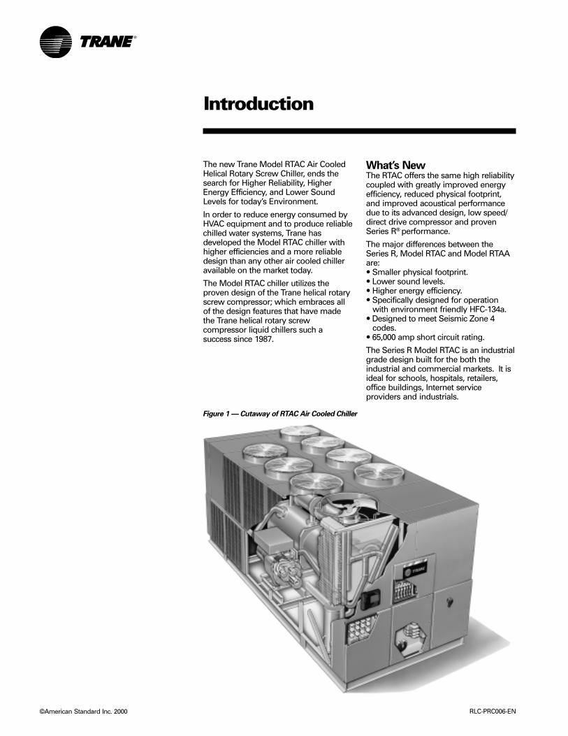
Figure 1 — Cutaway of RTAC Air Cooled Chiller
3
Introduction
Features and Benefits
OptionsUnit ConfigurationRefrigerant Cycle
Application Considerations
Selection Procedure
General Data
Performance Data
Adjustment FactorsCooling Performance
Electrical Data
Power Connection Wiring
Controls
Standalone Control and WiringGeneric BAS Control and WiringTrane ICS Control and Wiring
Dimension and Weights
Mechanical Specifications
Contents
RLC-PRC006-EN
The standard ARI rating condition(54/44 F and 95 F) and IPLV are ARIcertified. All other ratings, including thefollowing, are outside the scope of thecertification program and are excluded:• Glycol.• 50 Hz.• Unit sizes RTAC 200-250.
Water Chiller Systems Business Unit
2
4
9
12
13
15
23
25
28
34

RLC-PRC006-EN4
Features andBenefits
The Series R® Helical RotaryScrew Compressor• Unequaled Reliability. The next
generation Trane helical rotary screwcompressor is designed, built andtested to the same demanding andrugged standards as the Trane scrollcompressors, the centrifugalcompressors, and the previousgeneration helical rotary screwcompressors used in both air andwater cooled chillers for more than13 years.
• Years of research and testing. TheTrane helical rotary screw compressorhas amassed thousands of hours oftesting, much of it at severe operatingconditions beyond normal commercialair conditioning applications.
• Proven track record. The TraneCompany is the world’s largestmanufacturer of large helical rotarycompressors used for refrigeration.Over 90,000 compressors worldwidehave proven that the Trane helicalrotary screw compressor has areliability rate of 99.5 percent in the firstyear of operation – unequalled in theindustry.
• Resistance to liquid slugging. Therobust design of the Series Rcompressor can ingest amounts ofliquid refrigerant that would severelydamage reciprocating compressorvalves, piston rods and cylinders.
• Fewer moving parts. The helical rotaryscrew compressor has only two majorrotating parts: the male rotor and thefemale rotor. Unlike reciprocatingcompressors, the Trane helical rotaryscrew compressor has no pistons,connecting rods, suction and dischargevalves or mechanical oil pump. In fact,a typical reciprocating compressor has15 times as many critical parts as theSeries R compressor. Fewer movingparts lead to increased reliability andlonger life.
• Direct-drive, low speed, semi-hermeticcompressor for high efficiency andhigh reliability.
• Field serviceable compressor for easymaintenance.
• Suction gas-cooled motor. The motoroperates at lower temperatures forlonger motor life.
• Five minute start-to-start/two minutestop-to-start anti-recycle timer allowsfor closer water loop temperaturecontrol.
The sound levels of the Series R ModelRTAA have been steadily improved sinceits introduction. With the advent of theModel RTAC, sound levels are reducedsignificantly by addressing three majorsources: the compressor, the refrigerantpiping, and the condenser fans. First, thecompressor has been specificallydesigned to minimize sound generation.Second, the refrigerant components andpiping have been optimized to reducesound propagation throughout thesystem. And third, the condenser fanblades were engineered to reduce soundat its source. The result: Sound levelsachieved on the Model RTAC representthe lowest sound levels ever on Traneair-cooled screw compressor waterchillers.
5RLC-PRC006-EN
Superior Energy Efficiencylevels – the bar has beenraised
The standard efficiency Trane ModelRTAC has energy efficiency levels up to10.1 EER (COP 2.96), while the premiumefficiency units leap to energy efficiencylevels of 10.8 EER (COP 3.16). All unitsmeet or exceed ASHRAE 90.1 minimumrequirements.
The modern technology of the RTACutilizing an efficient direct-drivecompressor, a flooded evaporator, aunique liquid/vapor separator design, anelectronic expansion valve andrevolutionary Tracer™ Chiller Controlshave permitted Trane to achieve theseefficiency levels; unmatched in theindustry.
Improved AcousticalPerformance
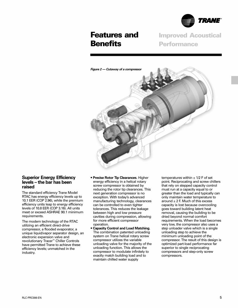
• Precise Rotor Tip Clearances. Higherenergy efficiency in a helical rotaryscrew compressor is obtained byreducing the rotor tip clearances. Thisnext generation compressor is noexception. With today’s advancedmanufacturing technology, clearancescan be controlled to even tightertolerances. This reduces the leakagebetween high and low pressurecavities during compression, allowingfor more efficient compressoroperation.
• Capacity Control and Load Matching.The combination patented unloadingsystem on Trane helical rotary screwcompressor utilizes the variableunloading valve for the majority of theunloading function. This allows thecompressor to modulate infinitely toexactly match building load and tomaintain chilled water supply
temperatures within ± 1/2 F of setpoint. Reciprocating and screw chillersthat rely on stepped capacity controlmust run at a capacity equal to orgreater than the load and typically canonly maintain water temperature toaround ± 2 F. Much of this excesscapacity is lost because overcoolinggoes toward building latent heatremoval, causing the building to bedried beyond normal comfortrequirements. When the load becomesvery low, the compressor also uses astep unloader valve which is a singleunloading step to achieve theminimum unloading point of thecompressor. The result of this design isoptimized part-load performance farsuperior to single reciprocatingcompressors and step-only screwcompressors.
Figure 2 — Cutaway of a compressor
Features andBenefits

RLC-PRC006-EN6
• Compact Physical Size. The TraneModel RTAC chiller averages a 20%reduction in physical footprint, whilethe greatest change is actually 40%smaller when compared against theprevious design. This improvementmakes the RTAC the smallest air-cooled chiller in the industry and aprime candidate for installations thathave space constraints. All physicalsizes were changed without sacrificingthe side clearances needed to supplyfresh airflow without coil starvation,the tightest operational clearances inthe industry.
• Close Spacing Installation. The air-cooled Series R® chiller has the tightestrecommended side clearance in theindustry, four feet, but that is not all. Insituations where equipment must beinstalled with less clearance thanrecommended, which frequentlyoccurs in retrofit applications, restrictedair flow is common. Conventionalchillers may not work at all. However,the air-cooled Series R chiller withAdaptive Control™ microprocessor willsimply make as much chilled water aspossible given the actual installedconditions, stay on line during anyunforeseen abnormal conditions, andoptimize its performance. Consult yourTrane sales engineer for more details.
• Factory Testing Means Trouble-FreeStart-Up. All air-cooled Series R chillersare given a complete functional test atthe factory. This computer-based testprogram completely checks thesensors, wiring, electrical components,microprocessor function,communication capability, expansionvalve performance and fans. Inaddition, each compressor is runtested to verify capacity and efficiency.Where applicable, each unit is factorypreset to the customer’s designconditions, an example would beleaving liquid temperature set point.The end result of this test program isthat the chiller arrives at the job sitefully tested and ready for operation.
• Factory Installed and Tested Controls/Options Speed Installation. All Series Rchiller options, including main powersupply disconnect, low ambientcontrol, ambient temperature sensor,low ambient lockout, communicationinterface and ice making controls arefactory installed and tested. Somemanufacturers send accessories inpieces to be field installed. With Trane,the customer saves on installationexpense and has assurance that ALLchiller controls/options have beentested and will function as expected.
SimpleInstallation
Features andBenefits

7RLC-PRC006-EN
The End Of Nuisance Trip-OutsAnd Unnecessary ServiceCalls?The Adaptive Control™ microprocessorsystem enhances the air-cooled Series Rchiller by providing the very latest chillercontrol technology. With the AdaptiveControl microprocessor, unnecessaryservice calls and unhappy tenants areavoided. The unit does not nuisance tripor unnecessarily shut down. Only whenthe Tracer Chiller Controls haveexhausted all possible corrective actionsand the unit is still violating an operatinglimit will the chiller shut down. Controlson other equipment typically shut downthe chiller, usually just when it is neededthe most.
For example:A typical five-year-old chiller with dirtycoils might trip-out on high pressurecutout on a 100 F (38 C) day in August. Ahot day is just when comfort cooling isneeded the most. In contrast, the air-cooled Series R chiller with an AdaptiveControl microprocessor will stage fanson, modulate electronic expansion valve,and modulate slide valve as itapproaches a high pressure cutout.Thereby keeping the chiller on-line whenyou need it the most.
System Options — Ice StorageTrane air-cooled chillers are well suitedfor ice production. The unique ability tooperate at decreased ambienttemperature while producing ice lends toroughly the same work seen by thecompressor. An air-cooled machinetypically switches to ice production atnight. Two things happen under thisassumption. First, the leaving brinetemperature from the evaporator islowered to around 22 to 24 F(-5.5 to –4.4 C). Second, the ambienttemperature has typically dropped about15 to 20 F (8.3 to 11 C) from the peakdaytime ambient. This effectively placesa lift on the compressors that is similarto daytime running conditions. Thechiller can operate in lower ambient atnight and successfully produce ice tosupplement the next day’s coolingdemands.
Superior Control withTracer® Chiller Controls
The Model RTAC produces ice bysupplying ice storage tanks with aconstant supply of glycol solution. Air-cooled chillers selected for these lowerleaving fluid temperatures are alsoselected for efficient production ofchilled fluid at nominal comfort coolingconditions. The ability of Trane chillers toserve “double duty” in ice productionand comfort cooling greatly reduces thecapital cost of ice storage systems.
When cooling is required, ice chilledglycol is pumped from the ice storagetanks directly to the cooling coils. Noexpensive heat exchanger is required.The glycol loop is a sealed system,eliminating expensive annual chemicaltreatment costs. The air-cooled chiller isalso available for comfort cooling duty atnominal cooling conditions andefficiencies. The modular concept ofglycol ice storage systems and theproven simplicity of Trane Tracer™
controls allow the successful blend ofreliability and energy savingperformance in any ice storageapplication.
The ice storage system is operated in sixdifferent modes: each optimized for theutility cost of the hour.1. Provide comfort cooling with chiller2. Provide comfort cooling with ice3. Provide comfort cooling with ice and
chiller4. Freeze ice storage5. Freeze ice storage when comfort
cooling is required6. Off
Tracer optimization software controlsoperation of the required equipment andaccessories to easily transition from onemode of operation to another. Forexample:
Even with ice storage systems there arenumerous hours when ice is neitherproduced or consumed, but saved. Inthis mode the chiller is the sole source ofcooling. For example, to cool thebuilding after all ice is produced butbefore high electrical demand chargestake effect, Tracer sets the air-cooledchiller leaving fluid set point to its mostefficient setting and starts the chiller,chiller pump, and load pump.
When electrical demand is high, the icepump is started and the chiller is eitherdemand limited or shut downcompletely. Tracer controls have theintelligence to optimally balance thecontribution of ice and chiller in meetingthe cooling load.
The capacity of the chiller plant isextended by operating the chiller and icein tandem. Tracer rations the ice,augmenting chiller capacity whilereducing cooling costs. When ice isproduced, Tracer will lower the air-cooled chiller leaving fluid set point andstart the chiller, ice and chiller pumps,and other accessories. Any incidentalloads that persists while producing icecan be addressed by starting the loadpump and drawing spent cooling fluidfrom the ice storage tanks.
For specific information on ice storageapplications, contact your local Tranesales office.
Features andBenefits
RLC-PRC006-EN8
High Efficiency/Performance OptionThis option provides oversized heatexchangers for two purposes. One, itallows the unit to be more energyefficient. Two, the unit will haveenhanced operation in high ambientconditions.
Low Temperature BrineThe hardware and software on the unitare factory set to handle lowtemperature brine applications (less than40°F/4.4°C).
Ice MakingThe unit controls are factory set tohandle ice making for thermal storageapplications.
Tracer/Summit CommunicationInterfacePermits bi-directional communication tothe Trane Integrated Comfort system.
Remote input optionsPermits remote chilled liquid set point,remote current limit set point, or both byaccepting a 4-20 mA or 2-10 Vdc analogsignal.
Remote output optionsPermits alarm relay outputs, ice makingoutputs, or both.
Chilled Water ResetThis option provides the control logicand field installed sensors to resetleaving chilled water temperature. Thesetpoint can be reset based off of eitherambient temperature or returnevaporator water temperature.
Architectural Louvered PanelsLouvered panels cover the completecondensing coil and the service areabeneath the coils.
Coil ProtectionLouvered panels which protect thecondenser coils only.
Access ProtectionA coated wire mesh which covers accessarea underneath the condenser coils.
Wye-Delta Compressor Start TypeThis option provides a reduced inrushstarter on 380-575 Volt machines.
Single/Dual Incoming Power LineConnectionEither a single or a dual point oftermination is available for incomingpower line connections.
Convenience OutletProvides a 15 amp, 115 volt (60 Hz) or 8amp, 220 volt (50 Hz) convenience outleton the unit.
Suction Service ValvesProvides a service valve on the suctionline of each circuit to facilitatecompressor servicing.
High Ambient OptionThe high ambient option consists ofspecial control logic to permit highambient (up to 125°F/51°C) operation.This option offers the best performancewhen coupled with the high efficiency/performance option.
Non-Fused Power Disconnect SwitchA non-fused disconnect switch with athrough-the-door handle is provided todisconnect main power.
Circuit BreakerA standard interrupting molded casecapacity circuit breaker (UL approved) isavailable. The circuit breaker can also beused to disconnect the chiller from mainpower with a through-the-door handleand comes pre-wired from the factorywith terminal block power connections.
Short Circuit RatingOffers a measure of safety for what thestarter panel enclosure is able towithstand in the event of an explosioncaused by a short circuit; protection upto 65,000 amps is available on mostvoltages.
Neoprene IsolatorsIsolators provide isolation betweenchiller and structure to help eliminatevibration transmission. Neopreneisolators are more effective andrecommended over spring isolators.
Flange KitProvides a kit that converts the groovedpipe evaporator water connections toflange connectors.
OptionsFeatures andBenefits
9RLC-PRC006-EN
Certain application constraints should beconsidered when sizing, selecting andinstalling Trane air-cooled Series Rchillers. Unit and system reliability isoften dependent upon properly andcompletely complying with theseconsiderations. When the applicationvaries from the guidelines presented, itshould be reviewed with your localTrane sales engineer.
Unit SizingUnit capacities are listed in theperformance data section. Intentionallyover-sizing a unit to assure adequatecapacity is not recommended. Erraticsystem operation and excessivecompressor cycling are often a directresult of an oversized chiller. In addition,an oversized unit is usually moreexpensive to purchase, install, andoperate. If over-sizing is desired,consider using two units.
Water TreatmentDirt, scale, products of corrosion andother foreign material will adverselyaffect heat transfer between the waterand system components. Foreign matterin the chilled water system can alsoincrease pressure drop and,consequently, reduce water flow. Properwater treatment must be determined
ApplicationConsiderations
locally, depending on the type of systemand local water characteristics. Neithersalt nor brackish water is recommendedfor use in Trane air-cooled Series Rchillers. Use of either will lead to ashortened life to an indeterminabledegree. The Trane Company encouragesthe employment of a reputable watertreatment specialist, familiar with localwater conditions, to assist in thisdetermination and in the establishmentof a proper water treatment program.
Effect Of Altitude On CapacityAir-cooled Series R chiller capacitiesgiven in the performance data tables arefor use at sea level. At elevationssubstantially above sea level, thedecreased air density will reducecondenser capacity and, therefore, unitcapacity and efficiency.
Ambient LimitationsTrane air-cooled Series R chillers aredesigned for year-round operation overa range of ambient temperatures. The aircooled Model RTAC chiller will operate inambient temperatures of 25 to 115°F/4 to46°C. Selecting the high ambient optionwill allow the chiller to operate inambient temperatures of 125°F/51°C. Foroperation outside of these ranges,contact the local Trane sales office.
Water Flow LimitsThe minimum water flow rates are givenin Tables G-1 and G-2. Evaporator flowrates below the tabulated values willresult in laminar flow causing freeze-upproblems, scaling, stratification and poorcontrol. The maximum evaporator waterflow rate is also given in the general datasection. Flow rates exceeding thoselisted may result in excessive tubeerosion.
Flow Rates out of RangeMany process cooling jobs require flowrates that cannot be met with theminimum and maximum publishedvalues within the Model RTACevaporator. A simple piping change canalleviate this problem. For example: Aplastic injection molding processrequires 80 gpm [5.1 lps] of 50°F [10°C]water and returns that water at 60°F[15.6°C]. The selected chiller can operateat these temperatures, but has aminimum flow rate of 120 gpm [7.6 lps].The following system can satisfy theprocess.
RLC-PRC006-EN10
ApplicationConsiderations
Leaving Water Temperature LimitsTrane air-cooled Series R chillers havethree distinct leaving water categories:standard, low temperature, and icemaking. The standard leaving solutiontemperature range is 40 to 60°F/4.4 to15.6°C. Low temperature machinesproduce leaving liquid temperatures lessthan 40°F/4.4°C. Since liquid supplytemperature set points less than40°F/4.4°C result in suction temperaturesat or below the freezing point of water, aglycol solution is required for all lowtemperature machines. Ice makingmachines have a leaving liquidtemperature range of 20 to 60°F/-6.7 to15.6°C. Ice making controls include dualset point controls and safeties for icemaking and standard coolingcapabilities. Consult your local Tranesales engineer for applications orselections involving low temperature orice making machines. The maximumwater temperature that can be circulatedthrough an evaporator when the unit isnot operating is 108°F/42°C.
Leaving Water Temperature out ofRangeSimilar to the flow rates above, manyprocess cooling jobs requiretemperature ranges that cannot be metwith the minimum and maximumpublished values for the Model RTACevaporator. A simple piping change canalleviate this problem. For example: Alaboratory load requires 120 gpm[7.6 lps] of water entering the process at85°F [29.4°C] and returning at 95°F[35°C]. The accuracy required is betterthan cooling tower can give. Theselected chiller has adequate capacity,but a maximum leaving chilled watertemperature of 60°F [15.6°C].
In the example shown, both the chillerand process flow rates are equal. This isnot necessary. For example, if the chillerhad a higher flow rate, there wouldsimply be more water bypassing andmixing with warm water.
Supply Water Temperature DropThe performance data for the Trane air-cooled Series R chiller is based on achilled water temperature drop of 10°F/5.5°C. Chilled water temperature dropsfrom 6 to 18°F/ 3.3 to 10°C may be usedas long as minimum and maximumwater temperature and minimum andmaximum flow rates are not violated.Temperature drops outside this rangeare beyond the optimum range forcontrol and may adversely affect themicrocomputer’s ability to maintain anacceptable supply water temperaturerange. Further, temperature drops of lessthan 6°F/3.3°C may result in inadequaterefrigerant superheat. Sufficientsuperheat is always a primary concern inany direct expansion refrigerant systemand is especially important in a packagechiller where the evaporator is closelycoupled to the compressor. Whentemperature drops are less than6°F/3.3°C, an evaporator runaround loopmay be required.
Variable Flow in the EvaporatorAn attractive chilled water system optionmay be a variable primary flow (VPF)system. VPF systems present buildingowners with several cost-saving benefitsthat are directly related to the pumps.The most obvious cost savings resultfrom eliminating the secondarydistribution pump, which in turn avoidsthe expense incurred with the associatedpiping connections (material, labor),electrical service, and variable-frequencydrive. Building owners often cite pump-related energy savings as the reason thatprompted them to install a VPF system.With the help of a software analysis toolsuch as System Analyzer™, TRACE®, orDOE-2, you can determine whether theanticipated energy savings justify theuse of variable primary flow in aparticular application. It may also beeasier to apply variable primary flow inan existing chilled-water plant. Unlike the“decoupled” design, the bypass can bepositioned at various points in thechilled-water loop and an additionalpump is unnecessary. The evaporator inthe Model RTAC can withstand up to 50percent water flow reduction as long asthis flow is equal or above the minimumflow rate requirements. Themicroprocessor and capacity controlalgorithms are designed to take amaximum of 10% change in water flowrate per minute.
11RLC-PRC006-EN
ApplicationConsiderations
Ice Storage Provides Reduced ElectricalDemandAn ice storage system uses a standardchiller to make ice at night when utilitiescharge less for electricity. The icesupplements or even replacesmechanical cooling during the day whenutility rates are at their highest. Thisreduced need for cooling results in bigutility cost savings.
Another advantage of ice storage isstandby cooling capacity. If the chiller isunable to operate, one or two days of icemay still be available to provide cooling.In that time the chiller can be repairedbefore building occupants feel any lossof comfort.
The Trane Model RTAC chiller is uniquelysuited to low temperature applicationslike ice storage because of the ambientrelief experienced at night. This allowsthe Model RTAC chiller to produce iceefficiently, with less stress on themachine.
Simple and smart control strategies areanother advantage the Model RTACchiller offers for ice storage applications.Trane Tracer® building managementsystems can actually anticipate howmuch ice needs to be made at night andoperate the system accordingly. Thecontrols are integrated right into thechiller. Two wires and preprogrammedsoftware dramatically reduce fieldinstallation cost and complexprogramming.
Short Water LoopsThe proper location of the temperaturecontrol sensor is in the supply (outlet)water connection or pipe. This locationallows the building to act as a buffer andassures a slowly changing return watertemperature. If there is not a sufficientvolume of water in the system to providean adequate buffer, temperature controlcan be lost, resulting in erratic systemoperation and excessive compressorcycling. A short water loop has the sameeffect as attempting to control from thebuilding return water. Typically, a two-minute water loop is sufficient to preventa short water loop. Therefore, as aguideline, ensure the volume of water inthe evaporator loop equals or exceedstwo times the evaporator flow rate. For arapidly changing load profile, theamount of volume should be increased.To prevent the effect of a short waterloop, the following items should begiven careful consideration: A storagetank or larger header pipe to increase thevolume of water in the system and,therefore, reduce the rate of change ofthe return water temperature.
Applications Types
• Comfort cooling.• Industrial process cooling.• Ice/thermal storage.• Low temperature process cooling.
RLC-PRC006-EN12
The chiller capacity tables cover themost frequently encountered leavingliquid temperatures. The tables reflect a10°F/5.6°C temperature drop through theevaporator. For other temperature drops,apply the appropriate Performance DataAdjustment Factors. For chilled brineselections, refer to Figures F-3 and 4 forEthylene and Propylene GlycolAdjustment Factors. To select a Trane air-cooled Series R® chiller, the followinginformation is required:
1Design load in tons of refrigeration
2Design chilled water temperature drop
3Design leaving chilled water temperature
4Design ambient temperature Evaporatorflow rates can be determined by usingthe following formulas:GPM = (Tons x 24) / Temperature Drop(Degrees F)ORL/S = (kW (Capacity) x .239) /Temperature Drop (Degrees C)
NOTE: Flow rates must fall within thelimits specified in Tables G-1 and G-2 (forGPM or for l/s).
SelectionProcedure
Selection ExampleGiven:Required System Load = 140 TonsLeaving Chilled Water Temperature(LCWT) = 44 F Chilled LiquidTemperature Drop = 10 F DesignAmbient Temperature = 95 FEvaporator Fouling Factor = 0.0001
1To calculate the required chilled waterflow rate we use the formula givenbelow:GPM = (140 Tons x 24) / 10 F = 336 GPM
2From Table P-1 (RTAC performancedata), an RTAC 140 standard at the givenconditions will produce 140.7 tons withcompressor power input of 171.1 kWand a unit EER of 9.9.
3To determine the evaporator pressuredrop use the flow rate (GPM) andpressure drop curves on page 16.Entering the curve at 336 gpm, thepressure drop for a nominal 140standard evaporator is 19 feet.
13RLC-PRC006-EN
General Data
Table G-1 — General Data — 140-240 Ton 60 Hz Units
Size 140 155 170 185 200 225 250Type STD HIGH STD HIGH STD HIGH STD HIGH STD HIGH STD STDCompressor
Quantity 2 2 2 2 2 2 2 2 2 2 2 2Evaporator
Water Storage (Gallons) 35 40 38 42 40 43 42 47 44 50 47 50(Liters) 132 151 141 156 151 163 156 176 163 188 176 188
Min. Flow (GPM) 170 198 182 215 198 215 215 237 215 259 237 259(L/Sec) 11 13 11 14 13 14 14 15 14 16 15 16
Max. Flow (GPM) 525 687 606 626 687 767 626 848 767 929 848 929(L/Sec) 33 43 38 39 43 48 39 54 48 59 54 59
CondenserQty of Coils 2 2 2 2 2 2 2 2 2 2 2 4Coil Length (inches) 156/156 180/180 180/156 216/180 180/180 216/216 216/180 252/216 216/216 252/252 252/216 252/252
(mm) 3962/3962 4572/4572 4572/3962 5486/4572 4572/4572 5486/5486 5486/4572 6401/5486 5486/5486 6401/6401 6401/5486 6401/6401
Coil Height (inches) 42 42 42 42 42 42 42 42 42 42 42 42(mm) 1067 1067 1067 1067 1067 1067 1067 1067 1067 1067 1067 1067
Fins/Ft 192 192 192 192 192 192 192 192 192 192 192 192Number of Rows 3 3 3 3 3 3 3 3 3 3 3 3
Condenser FansQuantity (1) 4/4 5/5 5/4 6/5 5/5 7/6 6/5 7/7 6/6 8/6 7/6 8/6Diameter (inches) 30 30 30 30 30 30 30 30 30 30 30 30
(mm) 762 762 762 762 762 762 762 762 762 762 762 762Total Airflow (cfm) 77000 91993 84542 101190 92087 110387 101296 119598 110506 128812 119725 128946
(m^3/hr) 130811 156281 143623 171906 156441 187530 172086 203178 187732 218831 203394 219059Nominal fan speed rpm 1140 1140 1140 1140 1140 1140 1140 1140 1140 1140 1140 1140
rps 19 19 19 19 19 19 19 19 19 19 19 19Tip Speed (ft/min) 8954 8954 8954 8954 8954 8954 8954 8954 8954 8954 8954 8954
M/S 45 45 45 45 45 45 45 45 45 45 45 45Motor Nominal (Ea) HP 1.5 1.5 1.5 1.5 1.5 1.5 1.5 1.5 1.5 1.5 1.5 1.5
kW 1.1 1.1 1.1 1.1 1.1 1.1 1.1 1.1 1.1 1.1 1.1 1.1Min Starting/Oper Ambient (2)
Std Unit (Deg F) 25 25 25 25 25 25 25 25 25 25 25 25(Deg C) -3.9 -3.9 -3.9 -3.9 -3.9 -3.9 -3.9 -3.9 -3.9 -3.9 -3.9 -3.9
General UnitRefrigerant HFC-134a HFC-134a HFC-134a HFC-134a HFC-134a HFC-134a HFC-134a HFC-134a HFC-134a HFC-134a HFC-134a HFC-134aNo. of IndependentRefrigerant Circuits 2 2 2 2 2 2 2 2 2 2 2 2% Min. Load 15 15 15 15 15 15 15 15 15 15 15 15Refrigerant Charge (1) (lb) 145/145 155/155 155/145 220/210 155/155 220/220 220/210 230/220 220/220 230/230 230/220 230/230
(kg) 66/66 70/70 70/66 100/95 70/70 100/100 100/95 104/100 100/100 104/104 104/100 104/104Oil Charge (1) (Gallons) 2.1/2.1 2.1/2.1 2.1/2.1 2.1/2.1 2.1/2.1 2.1/2.1 2.7/2.1 2.7/2.1 2.7/2.7 2.7/2.7 2.7/2.7 2.7/2.7
(Liters) 7.9/7.9 7.9/7.9 7.9/7.9 7.9/7.9 7.9/7.9 7.9/7.9 10.2/7.9 10.2/7.9 10.2/10.2 10.2/10.2 10.2/10.2 10.2/10.2Notes:1. Data containing information on two circuits shown as follows: CKT 1/CKT 22. Minimum start-up/operating ambient based on a 5 mph wind across the condenser
RLC-PRC006-EN14
Table G-2 —General Data — 140-200 Ton 50 Hz Units
Size 140 155 170 185 200
STD HIGH STD HIGH STD HIGH STD HIGH STD HIGHCompressor
Quantity 2 2 2 2 2 2 2 2 2 2Evaporator
Water Storage (Gallons) 35 40 38 42 40 44 42 47 44 50(Liters) 132 151 141 156 151 163 156 176 163 188
Min. Flow (GPM) 171 198 182 215 198 215 215 237 215 259(L/Sec) 11 13 11 14 13 14 14 15 14 16
Max. Flow (GPM) 525 687 606 626 684 767 626 848 767 929(L/Sec) 33 43 38 39 43 48 39 54 48 59
CondenserQty of Coils 2 2 2 2 2 2 2 2 2 4Coil Length (inches) 156/156 180/180 180/156 216/180 180/180 216/216 216/180 252/216 216/216 252/252
(mm) 3962/3962 4572/4572 4572/3962 5486/4572 4572/4572 5486/5486 5486/4572 6401/5486 5486/5486 6401/6401Coil Height (inches) 42 42 42 42 42 42 42 42 42 42
(mm) 1067 1067 1067 1067 1067 1067 1067 1067 1067 1067Fins/Ft 192 192 192 192 192 192 192 192 192 192Number of Rows 3 3 3 3 3 3 3 3 3 3
Condenser FansQuantity (1) 4/4 5/5 5/4 6/5 5/5 6/6 6/5 7/6 6/6 7/7Diameter (inches) 30 30 30 30 30 30 30 30 30 30
(mm) 762 762 762 762 762 762 762 762 762 762Total Airflow (cfm) 63346 75575 69507 83130 75671 90687 83236 98256 90803 105826
(m^3/hr) 107615 128390 118081 141225 128553 154063 141405 166921 154260 179781Nominal fan speed rpm 950 950 950 950 950 950 950 950 950 950
rps 15.8 15.8 15.8 15.8 15.8 15.8 15.8 15.8 15.8 15.8Tip Speed (ft/min) 7461 7461 7461 7461 7461 7461 7461 7461 7461 7461
M/S 38 38 38 38 38 38 38 38 38 38Motor Nominal (Ea) HP 1.5 1.5 1.5 1.5 1.5 1.5 1.5 1.5 1.5 1.5
kW 1.1 1.1 1.1 1.1 1.1 1.1 1.1 1.1 1.1 1.1Min Starting/Oper Ambient (2)
Std Unit (Deg F) 25 25 25 25 25 25 25 25 25 25(Deg C) -3.9 -3.9 -3.9 -3.9 -3.9 -3.9 -3.9 -3.9 -3.9 -3.9
General UnitRefrigerant HFC-134a HFC-134a HFC-134a HFC-134a HFC-134a HFC-134a HFC-134a HFC-134a HFC-134a HFC-134a
No. of IndependentRefrigerant Circuits 2 2 2 2 2 2 2 2 2 2% Min. Load 15 15 15 15 15 15 15 15 15 15Refrigerant Charge (1) (lb) 145/145 155/155 155/145 220/210 155/155 220/220 220/210 230/220 220/220 230/230
(kg) 66/66 70/70 70/66 100/95 70/70 100/100 100/95 104/100 100/100 104/104Oil Charge (1) (Gallons) 2.5/2.5 2.5/2.5 2.5/2.5 2.5/2.5 2.5/2.5 2.5/2.5 3.4/2.5 3.4/2.5 3.4/3.4 3.4/3.4
(Liters) 9.5/9.5 9.5/9.5 9.5/9.5 9.5/9.5 9.5/9.5 9.5/9.5 12.9/9.5 12.9/9.5 12.9/12.9 12.9/12.9Notes:1. Data containing information on two circuits shown as follows: CKT 1/CKT 22. Minimum start-up/operating ambient based on a 5 mph wind across the condenser
General Data

15RLC-PRC006-EN
PerformanceData
Table A-1 —Performance Data Adjustment Factors
Elevation Sea Level 2000 ft 4000 ft 6000 ftChilledWater
Fouling Temp.Factor Drop CAP GPM KW CAP GPM KW CAP GPM KW CAP GPM KW0.0001 8 180.1 538.6 224.5 178.2 532.9 227.4 176 526.2 230.8 173.4 518.6 234.9
10 180.6 432.2 224.8 178.7 427.5 227.7 176.4 422.1 231.2 173.9 416 235.312 181.1 361 225.1 179.1 357.1 228 176.8 352.6 231.5 174.2 347.4 235.614 181.4 310.1 225.3 179.4 306.8 228.3 177.2 302.9 231.7 174.5 298.4 235.916 181.7 271.8 225.5 179.7 268.9 228.5 177.4 265.4 231.9 174.8 261.5 236.1
0.00025 8 177.4 530.5 222.7 175.6 525 225.5 173.5 518.7 228.9 171 511.4 23310 178 425.8 223 176.1 421.4 225.9 174 416.3 229.3 171.5 410.4 233.412 178.5 355.9 223.4 176.6 352.2 226.2 174.5 347.9 229.7 172 342.9 233.814 178.9 305.8 223.7 177 302.6 226.5 174.8 298.9 230 172.3 294.6 234.116 179.2 268.2 223.9 177.4 265.3 226.8 175.2 262.1 230.2 172.6 258.3 234.3
Elevation Sea Level 2000 ft 4000 ft 6000 ftChilledWater
Fouling Temp.Factor Drop CAP GPM KW CAP GPM KW CAP GPM KW CAP GPM KW0.0001 8 0.997 1.246 0.999 0.987 1.233 1.012 0.975 1.217 1.027 0.960 1.200 1.045
10 1.000 1.000 1.000 0.989 0.989 1.013 0.977 0.977 1.028 0.963 0.963 1.04712 1.003 0.835 1.001 0.992 0.826 1.014 0.979 0.816 1.030 0.965 0.804 1.04814 1.004 0.717 1.002 0.993 0.710 1.016 0.981 0.701 1.031 0.966 0.690 1.04916 1.006 0.629 1.003 0.995 0.622 1.016 0.982 0.614 1.032 0.968 0.605 1.050
0.00025 8 0.982 1.227 0.991 0.972 1.215 1.003 0.961 1.200 1.018 0.947 1.183 1.03610 0.986 0.985 0.992 0.975 0.975 1.005 0.963 0.963 1.020 0.950 0.950 1.03812 0.988 0.823 0.994 0.978 0.815 1.006 0.966 0.805 1.022 0.952 0.793 1.04014 0.991 0.708 0.995 0.980 0.700 1.008 0.968 0.692 1.023 0.954 0.682 1.04116 0.992 0.621 0.996 0.982 0.614 1.009 0.970 0.606 1.024 0.956 0.598 1.042
AdjustmentFactors
Evaporator Water Pressure Drop
Pueblo Units
1
10
100
100 1000 10000Flow (GPM)
Pre
ssu
re D
rop
(ft
. of
H2O
)
1. 140 S
2. 155 S
3. 140 H, 170 S
4.155 H, 185 S
5. 170 H, 200 S
6. 185 H, 225 S (60 Hz)
7. 200 H, 250 S (60 Hz)
1
2 3
4
5 6
7
RLC-PRC006-EN16
PerformanceData
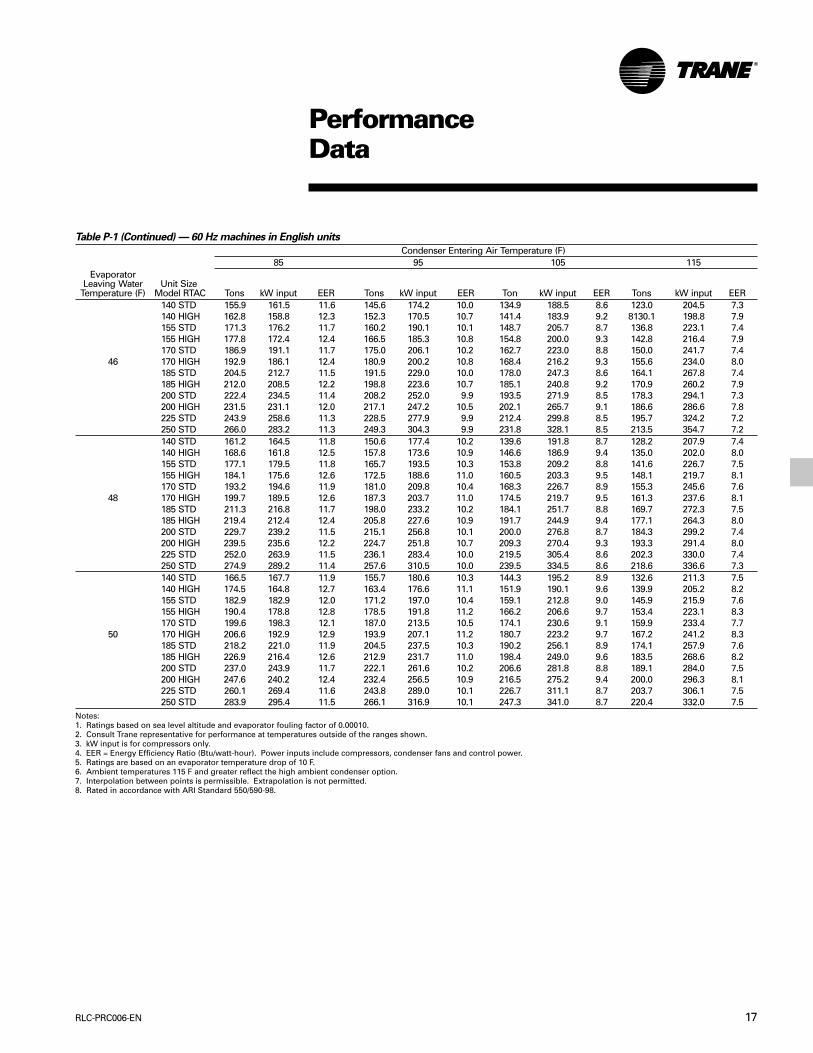
Table P-1 — 60 Hz machines in English units
Condenser Entering Air Temperature (F)85 95 105 115
EvaporatorLeaving Water Unit Size
Temperature (F) Model RTAC Tons kW input EER Tons kW input EER Ton kW input EER Tons kW input EER140 STD 140.5 152.6 11.0 131.0 165.0 9.5 121.2 179.1 8.1 111.1 194.7 6.8140 HIGH 145.8 150.4 11.6 136.2 161.9 10.1 126.3 175.0 8.7 116.0 189.7 7.3155 STD 154.4 166.6 11.1 144.2 180.2 9.6 133.6 195.5 8.2 122.7 212.5 6.9155 HIGH 159.4 163.4 11.7 149.1 176.1 10.2 138.4 190.5 8.7 127.3 206.6 7.4170 STD 168.5 180.7 11.2 157.5 195.4 9.7 146.1 212.0 8.3 134.4 230.4 7.0
40 170 HIGH 173.2 176.5 11.8 162.1 190.4 10.2 150.6 206.1 8.8 138.8 223.6 7.4185 STD 184.6 200.9 11.0 172.6 216.8 9.6 160.2 234.8 8.2 147.4 254.9 6.9185 HIGH 190.4 197.2 11.6 178.3 212.0 10.1 165.8 229.0 8.7 152.8 248.1 7.4200 STD 200.9 221.2 10.9 188.0 238.3 9.5 174.5 257.7 8.1 160.5 279.5 6.9200 HIGH 208.1 218.1 11.4 195.0 234.0 10.0 181.3 252.2 8.6 167.1 272.7 7.4225 STD 220.2 243.3 10.9 206.2 262.1 9.4 191.5 283.5 8.1 176.3 307.5 6.9250 STD 240.0 265.9 10.8 224.8 286.4 9.4 209.0 309.7 8.1 192.5 335.8 6.9140 STD 145.6 155.5 11.2 135.8 168.0 9.7 125.7 182.2 8.3 115.3 197.9 7.0140 HIGH 151.4 153.2 11.9 141.5 164.7 10.3 131.2 177.9 8.9 120.6 192.7 7.5155 STD 159.9 169.7 11.3 149.4 183.4 9.8 138.6 198.8 8.4 127.3 216.0 7.1155 HIGH 165.4 166.4 11.9 154.8 179.1 10.4 143.8 193.6 8.9 132.4 209.8 7.6170 STD 174.5 184.1 11.4 163.2 198.9 9.8 151.6 215.6 8.4 139.5 234.1 7.2
42 170 HIGH 179.7 179.7 12.0 168.2 193.6 10.4 156.4 209.4 9.0 144.3 227.0 7.6185 STD 191.1 204.7 11.2 178.8 220.8 9.7 166.1 238.9 8.3 152.9 259.1 7.1185 HIGH 197.5 200.9 11.8 185.1 215.8 10.3 172.1 232.9 8.9 158.7 252.0 7.6200 STD 208.0 225.5 11.1 194.6 242.8 9.6 180.8 262.4 8.3 166.4 284.3 7.0200 HIGH 215.8 222.4 11.6 202.2 238.3 10.2 188.1 256.6 8.8 173.5 277.3 7.5225 STD 228.0 248.3 11.0 213.5 267.3 9.6 198.4 288.8 8.2 182.7 313.0 7.0250 STD 248.6 271.5 11.0 232.9 292.2 9.6 216.5 315.7 8.2 199.4 342.0 7.0140 STD 150.7 158.4 11.4 140.7 171.1 9.9 130.3 185.3 8.4 119.5 201.2 7.1140 HIGH 157.0 156.0 12.1 146.9 167.6 10.5 136.3 180.8 9.0 125.3 195.7 7.7155 STD 165.6 172.9 11.5 154.8 186.7 9.9 143.6 202.2 8.5 132.0 219.5 7.2155 HIGH 171.5 169.4 12.2 160.6 182.2 10.6 149.2 196.8 9.1 137.5 213.1 7.7170 STD 180.7 187.5 11.6 169.1 202.5 10.0 157.1 219.2 8.6 144.7 237.9 7.3
44 170 HIGH 186.2 182.9 12.2 174.5 196.9 10.6 162.4 212.7 9.2 149.9 230.5 7.8185 STD 197.8 208.7 11.4 185.1 224.8 9.9 172.0 243.1 8.5 158.4 263.4 7.2185 HIGH 204.7 204.6 12.0 191.9 219.7 10.5 178.5 236.8 9.0 164.8 256.1 7.7200 STD 215.1 230.0 11.2 201.4 247.4 9.8 187.1 267.1 8.4 172.3 289.2 7.1200 HIGH 223.6 226.7 11.8 209.6 242.7 10.4 195.1 261.1 9.0 180.0 281.9 7.7225 STD 235.9 253.4 11.2 221.0 272.5 9.7 205.4 294.2 8.4 189.2 318.5 7.1250 STD 257.3 277.3 11.1 241.05 298.16 9.7 224.1 321.8 8.4 206.4 348.28 7.1
Notes:1. Ratings based on sea level altitude and evaporator fouling factor of 0.00010.2. Consult Trane representative for performance at temperatures outside of the ranges shown.3. kW input is for compressors only.4. EER = Energy Efficiency Ratio (Btu/watt-hour). Power inputs include compressors, condenser fans and control power.5. Ratings are based on an evaporator temperature drop of 10 F.6. Ambient temperatures 115 F and greater reflect the high ambient condenser option.7. Interpolation between points is permissible. Extrapolation is not permitted.8. Rated in accordance with ARI Standard 550/590-98.
17RLC-PRC006-EN
PerformanceData
Table P-1 (Continued) — 60 Hz machines in English units
Condenser Entering Air Temperature (F)85 95 105 115
EvaporatorLeaving Water Unit Size
Temperature (F) Model RTAC Tons kW input EER Tons kW input EER Ton kW input EER Tons kW input EER140 STD 155.9 161.5 11.6 145.6 174.2 10.0 134.9 188.5 8.6 123.0 204.5 7.3140 HIGH 162.8 158.8 12.3 152.3 170.5 10.7 141.4 183.9 9.2 8130.1 198.8 7.9155 STD 171.3 176.2 11.7 160.2 190.1 10.1 148.7 205.7 8.7 136.8 223.1 7.4155 HIGH 177.8 172.4 12.4 166.5 185.3 10.8 154.8 200.0 9.3 142.8 216.4 7.9170 STD 186.9 191.1 11.7 175.0 206.1 10.2 162.7 223.0 8.8 150.0 241.7 7.4
46 170 HIGH 192.9 186.1 12.4 180.9 200.2 10.8 168.4 216.2 9.3 155.6 234.0 8.0185 STD 204.5 212.7 11.5 191.5 229.0 10.0 178.0 247.3 8.6 164.1 267.8 7.4185 HIGH 212.0 208.5 12.2 198.8 223.6 10.7 185.1 240.8 9.2 170.9 260.2 7.9200 STD 222.4 234.5 11.4 208.2 252.0 9.9 193.5 271.9 8.5 178.3 294.1 7.3200 HIGH 231.5 231.1 12.0 217.1 247.2 10.5 202.1 265.7 9.1 186.6 286.6 7.8225 STD 243.9 258.6 11.3 228.5 277.9 9.9 212.4 299.8 8.5 195.7 324.2 7.2250 STD 266.0 283.2 11.3 249.3 304.3 9.9 231.8 328.1 8.5 213.5 354.7 7.2140 STD 161.2 164.5 11.8 150.6 177.4 10.2 139.6 191.8 8.7 128.2 207.9 7.4140 HIGH 168.6 161.8 12.5 157.8 173.6 10.9 146.6 186.9 9.4 135.0 202.0 8.0155 STD 177.1 179.5 11.8 165.7 193.5 10.3 153.8 209.2 8.8 141.6 226.7 7.5155 HIGH 184.1 175.6 12.6 172.5 188.6 11.0 160.5 203.3 9.5 148.1 219.7 8.1170 STD 193.2 194.6 11.9 181.0 209.8 10.4 168.3 226.7 8.9 155.3 245.6 7.6
48 170 HIGH 199.7 189.5 12.6 187.3 203.7 11.0 174.5 219.7 9.5 161.3 237.6 8.1185 STD 211.3 216.8 11.7 198.0 233.2 10.2 184.1 251.7 8.8 169.7 272.3 7.5185 HIGH 219.4 212.4 12.4 205.8 227.6 10.9 191.7 244.9 9.4 177.1 264.3 8.0200 STD 229.7 239.2 11.5 215.1 256.8 10.1 200.0 276.8 8.7 184.3 299.2 7.4200 HIGH 239.5 235.6 12.2 224.7 251.8 10.7 209.3 270.4 9.3 193.3 291.4 8.0225 STD 252.0 263.9 11.5 236.1 283.4 10.0 219.5 305.4 8.6 202.3 330.0 7.4250 STD 274.9 289.2 11.4 257.6 310.5 10.0 239.5 334.5 8.6 218.6 336.6 7.3140 STD 166.5 167.7 11.9 155.7 180.6 10.3 144.3 195.2 8.9 132.6 211.3 7.5140 HIGH 174.5 164.8 12.7 163.4 176.6 11.1 151.9 190.1 9.6 139.9 205.2 8.2155 STD 182.9 182.9 12.0 171.2 197.0 10.4 159.1 212.8 9.0 145.9 215.9 7.6155 HIGH 190.4 178.8 12.8 178.5 191.8 11.2 166.2 206.6 9.7 153.4 223.1 8.3170 STD 199.6 198.3 12.1 187.0 213.5 10.5 174.1 230.6 9.1 159.9 233.4 7.7
50 170 HIGH 206.6 192.9 12.9 193.9 207.1 11.2 180.7 223.2 9.7 167.2 241.2 8.3185 STD 218.2 221.0 11.9 204.5 237.5 10.3 190.2 256.1 8.9 174.1 257.9 7.6185 HIGH 226.9 216.4 12.6 212.9 231.7 11.0 198.4 249.0 9.6 183.5 268.6 8.2200 STD 237.0 243.9 11.7 222.1 261.6 10.2 206.6 281.8 8.8 189.1 284.0 7.5200 HIGH 247.6 240.2 12.4 232.4 256.5 10.9 216.5 275.2 9.4 200.0 296.3 8.1225 STD 260.1 269.4 11.6 243.8 289.0 10.1 226.7 311.1 8.7 203.7 306.1 7.5250 STD 283.9 295.4 11.5 266.1 316.9 10.1 247.3 341.0 8.7 220.4 332.0 7.5
Notes:1. Ratings based on sea level altitude and evaporator fouling factor of 0.00010.2. Consult Trane representative for performance at temperatures outside of the ranges shown.3. kW input is for compressors only.4. EER = Energy Efficiency Ratio (Btu/watt-hour). Power inputs include compressors, condenser fans and control power.5. Ratings are based on an evaporator temperature drop of 10 F.6. Ambient temperatures 115 F and greater reflect the high ambient condenser option.7. Interpolation between points is permissible. Extrapolation is not permitted.8. Rated in accordance with ARI Standard 550/590-98.

RLC-PRC006-EN18
PerformanceData
Table P-2 — 60 Hz machines in SI units
Condenser Entering Air Temperature (C)30 35 40 45
EvaporatorLeaving Water Unit Size kW kW kW kW kW kW kW kW
Temperature (c) Model RTAC cooling input COP output input COP output input COP output input COP140 STD 499.6 155.2 3.2 469.2 166.5 2.8 437.7 179.1 2.4 405.2 193.1 2.1140 HIGH 519.1 152.9 3.4 488.2 163.3 3.0 456.3 175.0 2.6 423.3 188.1 2.2155 STD 549.0 169.5 3.2 516.1 181.8 2.8 482.2 195.5 2.5 447.3 210.7 2.1155 HIGH 567.5 166.1 3.4 534.2 177.6 3.0 499.9 190.5 2.6 464.5 204.9 2.3170 STD 599.2 183.8 3.3 563.8 197.2 2.9 527.4 212.0 2.5 490.0 228.4 2.1
5 170 HIGH 616.4 179.4 3.4 580.7 192.0 3.0 543.9 206.0 2.6 506.2 221.7 2.3185 STD 656.3 204.3 3.2 617.9 218.8 2.8 578.1 234.9 2.5 537.2 252.8 2.1185 HIGH 677.8 200.4 3.4 638.8 213.9 3.0 598.5 229.1 2.6 557.1 246.1 2.3200 STD 714.2 225.0 3.2 672.6 240.5 2.8 629.4 258.0 2.4 584.7 277.3 2.1200 HIGH 740.6 221.7 3.3 698.3 236.1 3.0 654.4 252.4 2.6 609.0 270.7 2.2225 STD 783.0 247.6 3.2 737.8 264.7 2.8 690.9 283.9 2.4 642.2 305.2 2.1250 STD 853.7 270.6 3.2 804.7 289.3 2.8 753.8 310.2 2.4 701.0 333.4 2.1140 STD 532.0 160.5 3.3 500.0 172.0 2.9 466.8 184.8 2.5 432.5 198.9 2.2140 HIGH 554.6 157.9 3.5 522.1 168.5 3.1 488.4 180.3 2.7 453.5 193.6 2.3155 STD 584.5 175.2 3.3 549.9 187.7 2.9 514.3 201.6 2.5 477.5 217.0 2.2155 HIGH 606.0 171.5 3.5 570.9 183.1 3.1 534.7 196.2 2.7 497.5 210.7 2.4170 STD 637.8 190.0 3.4 600.7 203.6 3.0 562.5 218.6 2.6 523.3 235.1 2.2
7 170 HIGH 657.8 185.2 3.6 620.3 197.9 3.1 581.6 212.1 2.7 541.9 227.8 2.4185 STD 698.2 211.4 3.3 657.7 226.1 2.9 615.9 242.4 2.5 572.8 260.5 2.2185 HIGH 723.0 207.2 3.5 681.9 220.8 3.1 639.5 236.2 2.7 595.7 253.3 2.4200 STD 759.3 233.0 3.3 715.4 248.8 2.9 669.8 266.4 2.5 622.7 286.0 2.2200 HIGH 789.7 229.5 3.4 745.0 244.1 3.1 698.6 260.5 2.7 650.7 279.0 2.3225 STD 832.7 256.8 3.2 784.9 274.2 2.9 735.2 293.6 2.5 683.7 315.2 2.2250 STD 908.2 281.0 3.2 856.3 300.0 2.9 802.2 321.2 2.5 746.1 344.7 2.2140 STD 531.4 177.7 3.0 496.4 190.7 2.6 460.3 204.9 2.2 460.3 204.9 2.2140 HIGH 556.9 173.9 3.2 521.3 185.6 2.8 484.6 199.2 2.4 446.7 213.8 2.1155 STD 584.5 193.9 3.0 547.0 207.9 2.6 508.4 223.4 2.3 508.4 223.4 2.3155 HIGH 608.6 188.9 3.2 570.5 202.1 2.8 531.4 216.6 2.5 531.4 216.6 2.5170 STD 638.5 210.2 3.0 598.4 225.4 2.7 557.3 242.0 2.3 557.3 242.0 2.3
9 170 HIGH 660.9 204.0 3.2 620.4 218.3 2.8 578.7 234.2 2.5 578.7 234.2 2.5185 STD 698.4 233.6 3.0 654.4 250.2 2.6 609.1 268.4 2.3 609.1 268.4 2.3185 HIGH 726.1 228.0 3.2 681.5 243.5 2.8 635.5 260.7 2.4 635.5 260.7 2.4200 STD 759.0 257.3 2.9 711.0 275.2 2.6 661.5 295.0 2.2 661.5 295.0 2.2200 HIGH 792.8 252.3 3.1 743.9 268.9 2.8 693.4 287.5 2.4 693.4 287.5 2.4225 STD 832.9 284.0 2.9 780.4 303.7 2.6 726.0 325.4 2.2 726.0 325.4 2.2250 STD 908.9 311.1 2.9 851.5 332.6 2.6 791.9 356.3 2.2 791.9 356.3 2.2
Notes:1. Ratings based on sea level altitude and evaporator fouling factor of 0.0176.2. Consult Trane representative for performance at temperatures outside of the ranges shown.3. kW input is for compressors only.4. COP = Coefficient of Performance (kWo/kWi). Power inputs include compressors, condenser fans and control power.5. Ratings are based on an evaporator temperature drop of 5.6 C.6. Ambient temperatures 40 C and greater reflect the high ambient condenser option.7. Interpolation between points is permissible. Extrapolation is not permitted.8. Rated in accordance with ARI Standard 550/590-98.

19RLC-PRC006-EN
PerformanceData
Table P-3 — 50 Hz machines in English units
Condenser Entering Air Temperature (F)85 95 105 115
EvaporatorLeaving Water Unit Size
Temperature (F) Model RTAC Tons kW input EER Tons kW input EER Ton kW input EER Tons kW input EER140 STD 136.7 152.3 10.8 127.1 165.9 9.2 117.1 181.1 7.8 106.9 197.8 6.5140 HIGH 142.9 147.0 11.7 133.2 159.6 10.0 123.1 173.8 8.5 112.7 189.6 7.1155 STD 150.0 168.2 10.7 139.5 182.7 9.2 128.6 199.0 7.8 117.5 216.9 6.5
40 155 HIGH 156.0 162.2 11.5 145.4 175.7 9.9 134.4 190.9 8.4 123.2 207.9 7.1170 STD 163.5 184.4 10.6 152.1 199.8 9.1 140.3 217.1 7.8 128.2 236.3 6.5170 HIGH 169.2 177.5 11.4 157.7 191.9 9.9 145.9 208.1 8.4 133.7 226.3 7.1185 STD 181.2 203.4 10.7 168.9 220.4 9.2 156.1 239.3 7.8 141.5 257.1 6.6185 HIGH 188.2 196.7 11.5 175.8 212.5 9.9 162.9 230.4 8.5 149.6 250.3 7.2200 STD 199.2 222.6 10.7 185.9 241.1 9.3 172.1 261.8 7.9 155.1 278.6 6.7200 HIGH 207.7 216.3 11.5 194.2 233.5 10.0 180.3 252.9 8.6 165.8 274.6 7.2140 STD 141.5 155.3 10.9 131.6 169.1 9.3 121.4 184.4 7.9 108.5 196.1 6.6140 HIGH 148.2 149.8 11.9 138.2 162.5 10.2 127.8 176.9 8.7 117.2 192.7 7.3155 STD 155.1 171.7 10.8 144.3 186.4 9.3 133.2 202.7 7.9 118.8 214.4 6.7
42 155 HIGH 161.7 165.4 11.7 150.8 179.0 10.1 139.5 194.4 8.6 127.9 211.5 7.3170 STD 169.1 188.3 10.8 157.3 203.8 9.3 145.2 221.2 7.9 129.8 234.1 6.7170 HIGH 175.3 181.1 11.6 163.5 195.6 10.0 151.3 212.0 8.6 138.7 230.3 7.2185 STD 187.3 207.7 10.8 174.6 224.9 9.3 161.5 244.1 7.9 143.4 255.1 6.7185 HIGH 194.9 200.8 11.6 182.1 216.8 10.1 168.8 234.8 8.6 155.1 254.9 7.3200 STD 205.9 227.4 10.9 192.2 246.2 9.4 178.0 267.1 8.0 155.9 273.3 6.8200 HIGH 215.1 220.9 11.7 201.2 238.3 10.1 186.8 257.9 8.7 171.9 279.7 7.4140 STD 146.3 158.4 11.1 136.1 172.4 9.5 125.6 187.8 8.0 109.5 192.9 6.8140 HIGH 153.6 152.7 12.1 143.3 165.5 10.4 132.6 180.0 8.8 121.6 195.9 7.5155 STD 160.4 175.2 11.0 149.3 190.0 9.4 137.8 206.5 8.0 120.0 211.5 6.8
44 155 HIGH 167.4 168.7 11.9 156.2 182.4 10.3 144.6 197.9 8.8 132.7 215.1 7.4170 STD 174.7 192.3 10.9 162.6 208.0 9.4 150.1 225.5 8.0 130.7 230.2 6.8170 HIGH 181.4 184.8 11.8 169.3 199.4 10.2 156.7 215.9 8.7 143.8 234.3 7.4185 STD 193.5 212.2 10.9 180.5 229.5 9.4 166.9 248.9 8.0 144.5 250.9 6.9185 HIGH 201.8 205.0 11.8 188.6 221.1 10.2 174.9 239.3 8.8 160.7 259.5 7.4200 STD 212.7 232.3 11.0 198.6 251.3 9.5 184.0 272.5 8.1 157.4 269.6 7.0200 HIGH 222.6 225.6 11.8 208.3 243.1 10.3 193.46 262.94 8.8 178.1 285.0 7.5
Notes:1. Ratings based on sea level altitude and evaporator fouling factor of 0.00010.2. Consult Trane representative for performance at temperatures outside of the ranges shown.3. kW input is for compressors only.4. EER = Energy Efficiency Ratio (Btu/watt-hour). Power inputs include compressors, condenser fans and control power.5. Ratings are based on an evaporator temperature drop of 10 F.6. Ambient temperatures 115 F and greater reflect the high ambient condenser option.7. Interpolation between points is permissible. Extrapolation is not permitted.8. Rated in accordance with ARI Standard 550/590-98.

RLC-PRC006-EN20
PerformanceData
Table P-3 (continued) — 50 Hz machines in English units
Condenser Entering Air Temperature (F)85 95 105 115
EvaporatorLeaving Water Unit Size
Temperature (F) Model RTAC Tons kW input EER Tons kW input EER Ton kW input EER Tons kW input EER140 STD 151.2 161.6 11.2 140.7 175.7 9.6 130.0 191.2 8.2 110.3 189.3 7.0140 HIGH 159.0 155.6 12.3 148.4 168.6 10.6 137.5 183.1 9.0 126.2 199.2 7.6155 STD 165.7 178.8 11.1 154.2 193.8 9.6 142.5 210.4 8.1 121.1 208.2 7.0
46 155 HIGH 173.3 172.0 12.1 161.7 185.9 10.4 149.8 201.4 8.9 137.5 218.7 7.5170 STD 180.4 196.3 11.0 167.9 212.2 9.5 155.1 229.8 8.1 132.1 227.3 7.0170 HIGH 187.7 188.6 11.9 175.1 203.3 10.3 162.2 219.9 8.9 148.9 238.4 7.5185 STD 199.8 216.7 11.1 186.4 234.2 9.5 172.4 253.8 8.2 145.4 246.3 7.1185 HIGH 208.7 209.3 12.0 196.1 225.5 10.4 181.0 243.8 8.9 166.4 264.2 7.6200 STD 219.6 237.4 11.1 205.1 256.6 9.6 190.0 278.0 8.2 158.8 265.4 7.2200 HIGH 230.2 230.3 12.0 215.5 248.1 10.4 200.2 268.1 9.0 184.4 290.5 7.6140 STD 156.1 164.9 11.4 145.4 179.0 9.7 134.3 194.7 8.3 111.6 186.8 7.2140 HIGH 164.6 158.6 12.5 153.7 171.7 10.7 142.4 186.3 9.2 130.8 202.5 7.8155 STD 171.0 182.5 11.2 159.3 197.6 9.7 147.2 214.4 8.2 122.1 204.6 7.2
48 155 HIGH 179.2 175.5 12.3 167.3 189.4 10.6 155.0 205.1 9.1 142.4 222.4 7.7170 STD 186.1 200.5 11.1 173.3 216.5 9.6 160.2 234.2 8.2 132.7 222.5 7.2170 HIGH 194.0 192.4 12.1 181.1 207.2 10.5 167.8 223.9 9.0 154.1 242.5 7.6185 STD 206.1 221.4 11.2 192.3 239.1 9.7 176.3 255.2 8.3 146.1 241.1 7.3185 HIGH 215.6 213.6 12.1 201.7 230.0 10.5 187.2 248.5 9.0 172.2 269.0 7.7200 STD 226.5 242.5 11.2 211.6 261.9 9.7 193.0 276.9 8.4 160.1 260.7 7.4200 HIGH 237.9 235.2 12.1 222.8 253.2 10.6 207.0 273.4 9.1 189.7 293.7 7.7140 STD 161.1 168.2 11.5 150.1 182.5 9.9 136.1 192.8 8.5 112.1 182.6 7.4140 HIGH 170.2 161.7 12.6 159.0 174.9 10.9 147.4 189.6 9.3 135.5 205.8 7.9155 STD 176.4 186.3 11.4 164.3 201.5 9.8 147.9 210.0 8.5 122.9 200.6 7.4
50 155 HIGH 185.2 178.9 12.4 173.0 193.0 10.8 160.3 208.7 9.2 147.4 226.2 7.8170 STD 191.9 204.7 11.2 178.8 220.8 9.7 161.3 230.2 8.4 134.1 219.5 7.3170 HIGH 200.3 196.3 12.2 187.1 211.3 10.6 173.4 228.0 9.1 159.4 246.7 7.8185 STD 212.5 226.1 11.3 198.3 244.0 9.8 178.5 252.7 8.5 146.3 235.0 7.5185 HIGH 222.7 218.1 12.3 208.3 234.6 10.7 193.4 253.2 9.2 174.5 266.6 7.9200 STD 233.5 247.7 11.3 218.2 267.4 9.8 193.8 270.8 8.6 161.2 255.5 7.6200 HIGH 245.7 240.2 12.3 230.1 258.3 10.7 213.9 278.8 9.2 191.6 290.0 7.9
Notes:1. Ratings based on sea level altitude and evaporator fouling factor of 0.00010.2. Consult Trane representative for performance at temperatures outside of the ranges shown.3. kW input is for compressors only.4. EER = Energy Efficiency Ratio (Btu/watt-hour). Power inputs include compressors, condenser fans and control power.5. Ratings are based on an evaporator temperature drop of 10 F.6. Ambient temperatures 115 F and greater reflect the high ambient condenser option.7. Interpolation between points is permissible. Extrapolation is not permitted.8. Rated in accordance with ARI Standard 550/590-98.
21RLC-PRC006-EN
PerformanceData
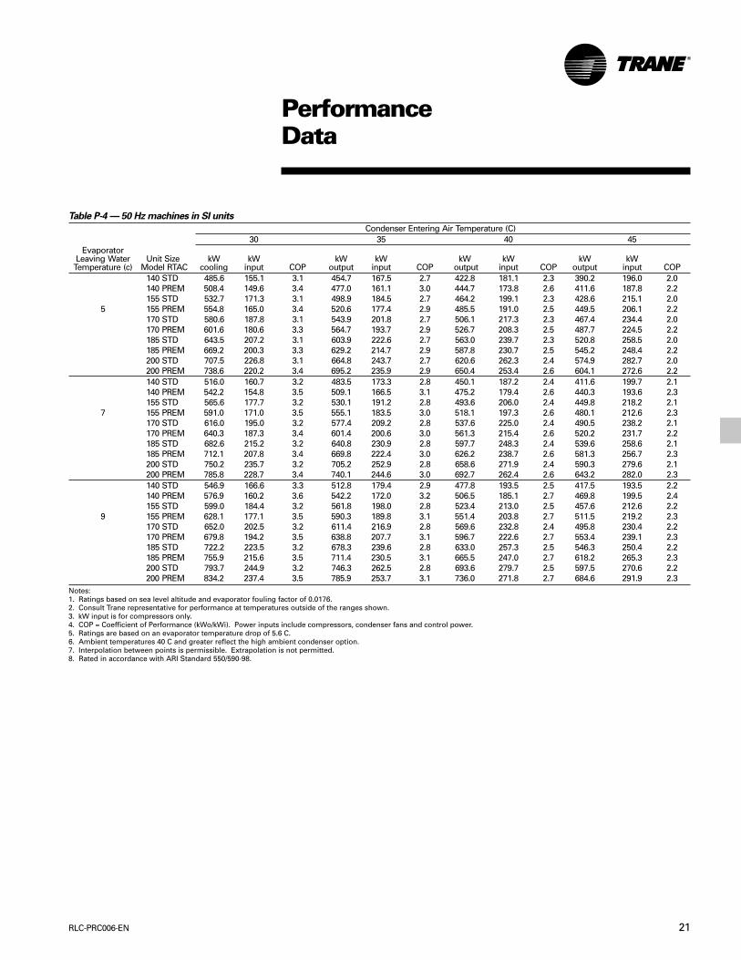
Table P-4 — 50 Hz machines in SI units
Condenser Entering Air Temperature (C)30 35 40 45
EvaporatorLeaving Water Unit Size kW kW kW kW kW kW kW kW
Temperature (c) Model RTAC cooling input COP output input COP output input COP output input COP140 STD 485.6 155.1 3.1 454.7 167.5 2.7 422.8 181.1 2.3 390.2 196.0 2.0140 PREM 508.4 149.6 3.4 477.0 161.1 3.0 444.7 173.8 2.6 411.6 187.8 2.2155 STD 532.7 171.3 3.1 498.9 184.5 2.7 464.2 199.1 2.3 428.6 215.1 2.0
5 155 PREM 554.8 165.0 3.4 520.6 177.4 2.9 485.5 191.0 2.5 449.5 206.1 2.2170 STD 580.6 187.8 3.1 543.9 201.8 2.7 506.1 217.3 2.3 467.4 234.4 2.0170 PREM 601.6 180.6 3.3 564.7 193.7 2.9 526.7 208.3 2.5 487.7 224.5 2.2185 STD 643.5 207.2 3.1 603.9 222.6 2.7 563.0 239.7 2.3 520.8 258.5 2.0185 PREM 669.2 200.3 3.3 629.2 214.7 2.9 587.8 230.7 2.5 545.2 248.4 2.2200 STD 707.5 226.8 3.1 664.8 243.7 2.7 620.6 262.3 2.4 574.9 282.7 2.0200 PREM 738.6 220.2 3.4 695.2 235.9 2.9 650.4 253.4 2.6 604.1 272.6 2.2140 STD 516.0 160.7 3.2 483.5 173.3 2.8 450.1 187.2 2.4 411.6 199.7 2.1140 PREM 542.2 154.8 3.5 509.1 166.5 3.1 475.2 179.4 2.6 440.3 193.6 2.3155 STD 565.6 177.7 3.2 530.1 191.2 2.8 493.6 206.0 2.4 449.8 218.2 2.1
7 155 PREM 591.0 171.0 3.5 555.1 183.5 3.0 518.1 197.3 2.6 480.1 212.6 2.3170 STD 616.0 195.0 3.2 577.4 209.2 2.8 537.6 225.0 2.4 490.5 238.2 2.1170 PREM 640.3 187.3 3.4 601.4 200.6 3.0 561.3 215.4 2.6 520.2 231.7 2.2185 STD 682.6 215.2 3.2 640.8 230.9 2.8 597.7 248.3 2.4 539.6 258.6 2.1185 PREM 712.1 207.8 3.4 669.8 222.4 3.0 626.2 238.7 2.6 581.3 256.7 2.3200 STD 750.2 235.7 3.2 705.2 252.9 2.8 658.6 271.9 2.4 590.3 279.6 2.1200 PREM 785.8 228.7 3.4 740.1 244.6 3.0 692.7 262.4 2.6 643.2 282.0 2.3140 STD 546.9 166.6 3.3 512.8 179.4 2.9 477.8 193.5 2.5 417.5 193.5 2.2140 PREM 576.9 160.2 3.6 542.2 172.0 3.2 506.5 185.1 2.7 469.8 199.5 2.4155 STD 599.0 184.4 3.2 561.8 198.0 2.8 523.4 213.0 2.5 457.6 212.6 2.2
9 155 PREM 628.1 177.1 3.5 590.3 189.8 3.1 551.4 203.8 2.7 511.5 219.2 2.3170 STD 652.0 202.5 3.2 611.4 216.9 2.8 569.6 232.8 2.4 495.8 230.4 2.2170 PREM 679.8 194.2 3.5 638.8 207.7 3.1 596.7 222.6 2.7 553.4 239.1 2.3185 STD 722.2 223.5 3.2 678.3 239.6 2.8 633.0 257.3 2.5 546.3 250.4 2.2185 PREM 755.9 215.6 3.5 711.4 230.5 3.1 665.5 247.0 2.7 618.2 265.3 2.3200 STD 793.7 244.9 3.2 746.3 262.5 2.8 693.6 279.7 2.5 597.5 270.6 2.2200 PREM 834.2 237.4 3.5 785.9 253.7 3.1 736.0 271.8 2.7 684.6 291.9 2.3
Notes:1. Ratings based on sea level altitude and evaporator fouling factor of 0.0176.2. Consult Trane representative for performance at temperatures outside of the ranges shown.3. kW input is for compressors only.4. COP = Coefficient of Performance (kWo/kWi). Power inputs include compressors, condenser fans and control power.5. Ratings are based on an evaporator temperature drop of 5.6 C.6. Ambient temperatures 40 C and greater reflect the high ambient condenser option.7. Interpolation between points is permissible. Extrapolation is not permitted.8. Rated in accordance with ARI Standard 550/590-98.
RLC-PRC006-EN22
PerformanceData
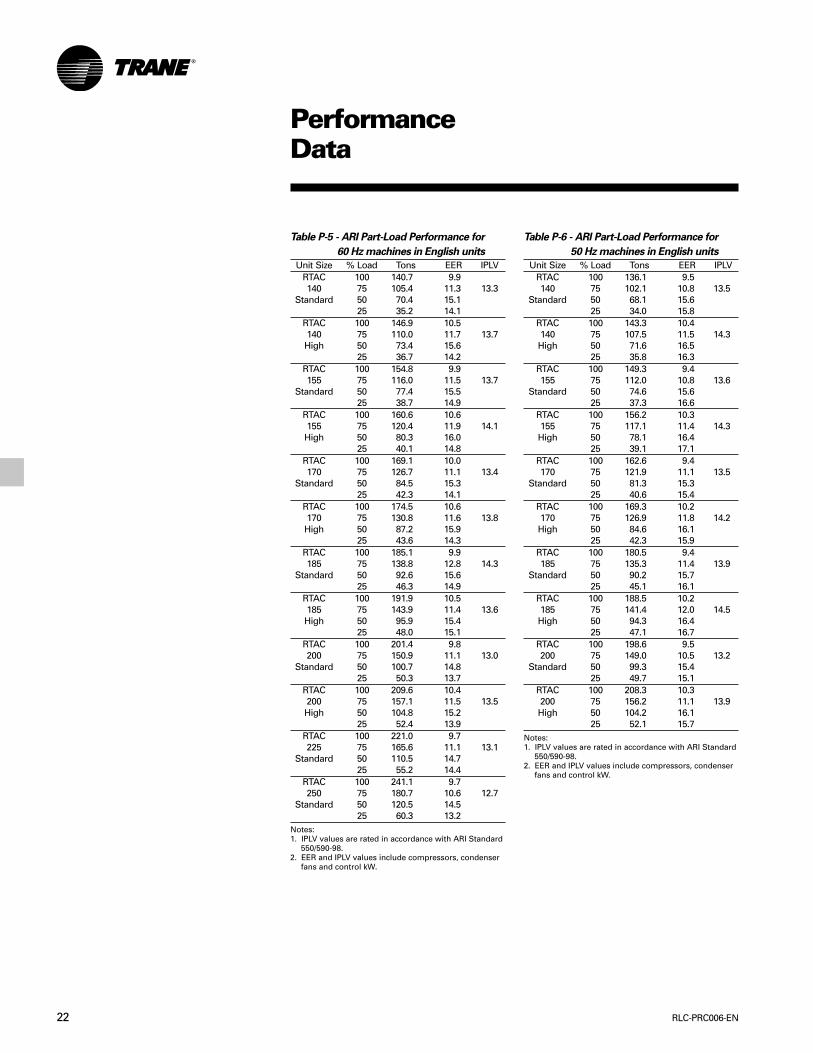
Table P-5 - ARI Part-Load Performance for
60 Hz machines in English units
Unit Size % Load Tons EER IPLVRTAC 100 140.7 9.9140 75 105.4 11.3 13.3
Standard 50 70.4 15.125 35.2 14.1
RTAC 100 146.9 10.5140 75 110.0 11.7 13.7High 50 73.4 15.6
25 36.7 14.2RTAC 100 154.8 9.9155 75 116.0 11.5 13.7
Standard 50 77.4 15.525 38.7 14.9
RTAC 100 160.6 10.6155 75 120.4 11.9 14.1High 50 80.3 16.0
25 40.1 14.8RTAC 100 169.1 10.0170 75 126.7 11.1 13.4
Standard 50 84.5 15.325 42.3 14.1
RTAC 100 174.5 10.6170 75 130.8 11.6 13.8High 50 87.2 15.9
25 43.6 14.3RTAC 100 185.1 9.9185 75 138.8 12.8 14.3
Standard 50 92.6 15.625 46.3 14.9
RTAC 100 191.9 10.5185 75 143.9 11.4 13.6High 50 95.9 15.4
25 48.0 15.1RTAC 100 201.4 9.8200 75 150.9 11.1 13.0
Standard 50 100.7 14.825 50.3 13.7
RTAC 100 209.6 10.4200 75 157.1 11.5 13.5High 50 104.8 15.2
25 52.4 13.9RTAC 100 221.0 9.7225 75 165.6 11.1 13.1
Standard 50 110.5 14.725 55.2 14.4
RTAC 100 241.1 9.7250 75 180.7 10.6 12.7
Standard 50 120.5 14.525 60.3 13.2
Notes:1. IPLV values are rated in accordance with ARI Standard
550/590-98.2. EER and IPLV values include compressors, condenser
fans and control kW.
Table P-6 - ARI Part-Load Performance for
50 Hz machines in English units
Unit Size % Load Tons EER IPLVRTAC 100 136.1 9.5140 75 102.1 10.8 13.5
Standard 50 68.1 15.625 34.0 15.8
RTAC 100 143.3 10.4140 75 107.5 11.5 14.3High 50 71.6 16.5
25 35.8 16.3RTAC 100 149.3 9.4155 75 112.0 10.8 13.6
Standard 50 74.6 15.625 37.3 16.6
RTAC 100 156.2 10.3155 75 117.1 11.4 14.3High 50 78.1 16.4
25 39.1 17.1RTAC 100 162.6 9.4170 75 121.9 11.1 13.5
Standard 50 81.3 15.325 40.6 15.4
RTAC 100 169.3 10.2170 75 126.9 11.8 14.2High 50 84.6 16.1
25 42.3 15.9RTAC 100 180.5 9.4185 75 135.3 11.4 13.9
Standard 50 90.2 15.725 45.1 16.1
RTAC 100 188.5 10.2185 75 141.4 12.0 14.5High 50 94.3 16.4
25 47.1 16.7RTAC 100 198.6 9.5200 75 149.0 10.5 13.2
Standard 50 99.3 15.425 49.7 15.1
RTAC 100 208.3 10.3200 75 156.2 11.1 13.9High 50 104.2 16.1
25 52.1 15.7Notes:1. IPLV values are rated in accordance with ARI Standard
550/590-98.2. EER and IPLV values include compressors, condenser
fans and control kW.
23RLC-PRC006-EN
ElectricalData
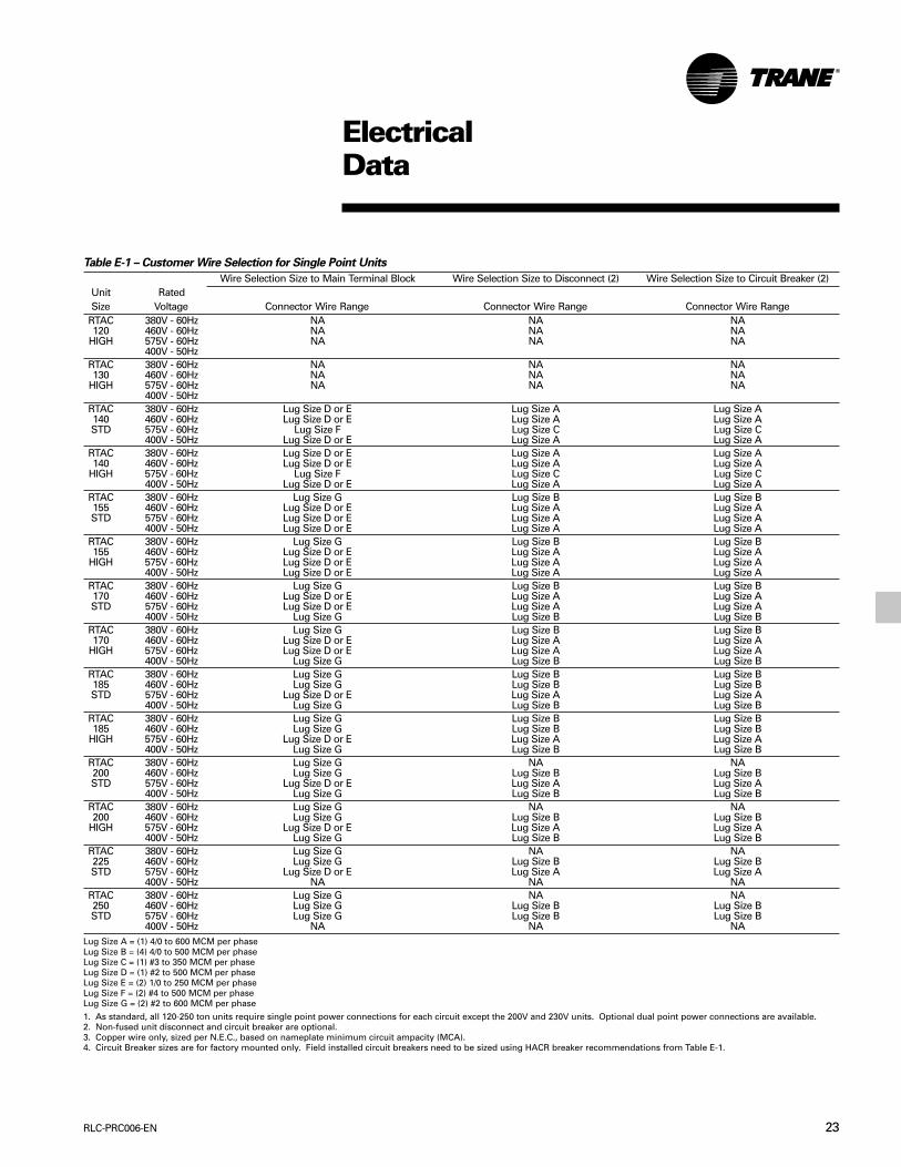
Table E-1 – Customer Wire Selection for Single Point Units
Wire Selection Size to Main Terminal Block Wire Selection Size to Disconnect (2) Wire Selection Size to Circuit Breaker (2)Unit RatedSize Voltage Connector Wire Range Connector Wire Range Connector Wire Range
RTAC 380V - 60Hz NA NA NA120 460V - 60Hz NA NA NA
HIGH 575V - 60Hz NA NA NA400V - 50Hz
RTAC 380V - 60Hz NA NA NA130 460V - 60Hz NA NA NA
HIGH 575V - 60Hz NA NA NA400V - 50Hz
RTAC 380V - 60Hz Lug Size D or E Lug Size A Lug Size A140 460V - 60Hz Lug Size D or E Lug Size A Lug Size ASTD 575V - 60Hz Lug Size F Lug Size C Lug Size C
400V - 50Hz Lug Size D or E Lug Size A Lug Size ARTAC 380V - 60Hz Lug Size D or E Lug Size A Lug Size A140 460V - 60Hz Lug Size D or E Lug Size A Lug Size A
HIGH 575V - 60Hz Lug Size F Lug Size C Lug Size C400V - 50Hz Lug Size D or E Lug Size A Lug Size A
RTAC 380V - 60Hz Lug Size G Lug Size B Lug Size B155 460V - 60Hz Lug Size D or E Lug Size A Lug Size ASTD 575V - 60Hz Lug Size D or E Lug Size A Lug Size A
400V - 50Hz Lug Size D or E Lug Size A Lug Size ARTAC 380V - 60Hz Lug Size G Lug Size B Lug Size B155 460V - 60Hz Lug Size D or E Lug Size A Lug Size A
HIGH 575V - 60Hz Lug Size D or E Lug Size A Lug Size A400V - 50Hz Lug Size D or E Lug Size A Lug Size A
RTAC 380V - 60Hz Lug Size G Lug Size B Lug Size B170 460V - 60Hz Lug Size D or E Lug Size A Lug Size ASTD 575V - 60Hz Lug Size D or E Lug Size A Lug Size A
400V - 50Hz Lug Size G Lug Size B Lug Size BRTAC 380V - 60Hz Lug Size G Lug Size B Lug Size B170 460V - 60Hz Lug Size D or E Lug Size A Lug Size A
HIGH 575V - 60Hz Lug Size D or E Lug Size A Lug Size A400V - 50Hz Lug Size G Lug Size B Lug Size B
RTAC 380V - 60Hz Lug Size G Lug Size B Lug Size B185 460V - 60Hz Lug Size G Lug Size B Lug Size BSTD 575V - 60Hz Lug Size D or E Lug Size A Lug Size A
400V - 50Hz Lug Size G Lug Size B Lug Size BRTAC 380V - 60Hz Lug Size G Lug Size B Lug Size B185 460V - 60Hz Lug Size G Lug Size B Lug Size B
HIGH 575V - 60Hz Lug Size D or E Lug Size A Lug Size A400V - 50Hz Lug Size G Lug Size B Lug Size B
RTAC 380V - 60Hz Lug Size G NA NA200 460V - 60Hz Lug Size G Lug Size B Lug Size BSTD 575V - 60Hz Lug Size D or E Lug Size A Lug Size A
400V - 50Hz Lug Size G Lug Size B Lug Size BRTAC 380V - 60Hz Lug Size G NA NA200 460V - 60Hz Lug Size G Lug Size B Lug Size B
HIGH 575V - 60Hz Lug Size D or E Lug Size A Lug Size A400V - 50Hz Lug Size G Lug Size B Lug Size B
RTAC 380V - 60Hz Lug Size G NA NA225 460V - 60Hz Lug Size G Lug Size B Lug Size BSTD 575V - 60Hz Lug Size D or E Lug Size A Lug Size A
400V - 50Hz NA NA NARTAC 380V - 60Hz Lug Size G NA NA250 460V - 60Hz Lug Size G Lug Size B Lug Size BSTD 575V - 60Hz Lug Size G Lug Size B Lug Size B
400V - 50Hz NA NA NALug Size A = (1) 4/0 to 600 MCM per phaseLug Size B = (4) 4/0 to 500 MCM per phaseLug Size C = (1) #3 to 350 MCM per phaseLug Size D = (1) #2 to 500 MCM per phaseLug Size E = (2) 1/0 to 250 MCM per phaseLug Size F = (2) #4 to 500 MCM per phaseLug Size G = (2) #2 to 600 MCM per phase
1. As standard, all 120-250 ton units require single point power connections for each circuit except the 200V and 230V units. Optional dual point power connections are available.2. Non-fused unit disconnect and circuit breaker are optional.3. Copper wire only, sized per N.E.C., based on nameplate minimum circuit ampacity (MCA).4. Circuit Breaker sizes are for factory mounted only. Field installed circuit breakers need to be sized using HACR breaker recommendations from Table E-1.
RLC-PRC006-EN24
ElectricalData
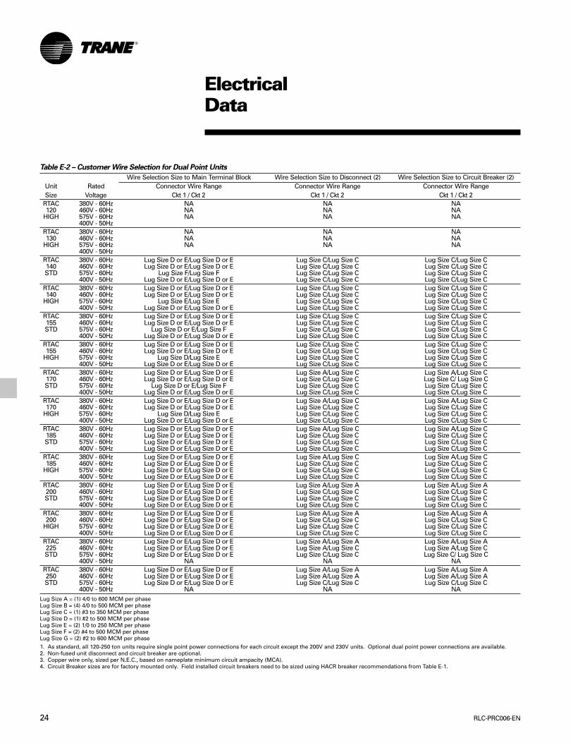
Table E-2 – Customer Wire Selection for Dual Point Units
Wire Selection Size to Main Terminal Block Wire Selection Size to Disconnect (2) Wire Selection Size to Circuit Breaker (2)Unit Rated Connector Wire Range Connector Wire Range Connector Wire RangeSize Voltage Ckt 1 / Ckt 2 Ckt 1 / Ckt 2 Ckt 1 / Ckt 2
RTAC 380V - 60Hz NA NA NA120 460V - 60Hz NA NA NA
HIGH 575V - 60Hz NA NA NA400V - 50Hz
RTAC 380V - 60Hz NA NA NA130 460V - 60Hz NA NA NA
HIGH 575V - 60Hz NA NA NA400V - 50Hz
RTAC 380V - 60Hz Lug Size D or E/Lug Size D or E Lug Size C/Lug Size C Lug Size C/Lug Size C140 460V - 60Hz Lug Size D or E/Lug Size D or E Lug Size C/Lug Size C Lug Size C/Lug Size CSTD 575V - 60Hz Lug Size F/Lug Size F Lug Size C/Lug Size C Lug Size C/Lug Size C
400V - 50Hz Lug Size D or E/Lug Size D or E Lug Size C/Lug Size C Lug Size C/Lug Size CRTAC 380V - 60Hz Lug Size D or E/Lug Size D or E Lug Size C/Lug Size C Lug Size C/Lug Size C140 460V - 60Hz Lug Size D or E/Lug Size D or E Lug Size C/Lug Size C Lug Size C/Lug Size C
HIGH 575V - 60Hz Lug Size E/Lug Size E Lug Size C/Lug Size C Lug Size C/Lug Size C400V - 50Hz Lug Size D or E/Lug Size D or E Lug Size C/Lug Size C Lug Size C/Lug Size C
RTAC 380V - 60Hz Lug Size D or E/Lug Size D or E Lug Size C/Lug Size C Lug Size C/Lug Size C155 460V - 60Hz Lug Size D or E/Lug Size D or E Lug Size C/Lug Size C Lug Size C/Lug Size CSTD 575V - 60Hz Lug Size D or E/Lug Size F Lug Size C/Lug Size C Lug Size C/Lug Size C
400V - 50Hz Lug Size D or E/Lug Size D or E Lug Size C/Lug Size C Lug Size C/Lug Size CRTAC 380V - 60Hz Lug Size D or E/Lug Size D or E Lug Size C/Lug Size C Lug Size C/Lug Size C155 460V - 60Hz Lug Size D or E/Lug Size D or E Lug Size C/Lug Size C Lug Size C/Lug Size C
HIGH 575V - 60Hz Lug Size D/Lug Size E Lug Size C/Lug Size C Lug Size C/Lug Size C400V - 50Hz Lug Size D or E/Lug Size D or E Lug Size C/Lug Size C Lug Size C/Lug Size C
RTAC 380V - 60Hz Lug Size D or E/Lug Size D or E Lug Size A/Lug Size C Lug Size A/Lug Size C170 460V - 60Hz Lug Size D or E/Lug Size D or E Lug Size C/Lug Size C Lug Size C/ Lug Size CSTD 575V - 60Hz Lug Size D or E/Lug Size F Lug Size C/Lug Size C Lug Size C/Lug Size C
400V - 50Hz Lug Size D or E/Lug Size D or E Lug Size C/Lug Size C Lug Size C/Lug Size CRTAC 380V - 60Hz Lug Size D or E/Lug Size D or E Lug Size A/Lug Size C Lug Size A/Lug Size C170 460V - 60Hz Lug Size D or E/Lug Size D or E Lug Size C/Lug Size C Lug Size C/Lug Size C
HIGH 575V - 60Hz Lug Size D/Lug Size E Lug Size C/Lug Size C Lug Size C/Lug Size C400V - 50Hz Lug Size D or E/Lug Size D or E Lug Size C/Lug Size C Lug Size C/Lug Size C
RTAC 380V - 60Hz Lug Size D or E/Lug Size D or E Lug Size A/Lug Size C Lug Size A/Lug Size C185 460V - 60Hz Lug Size D or E/Lug Size D or E Lug Size C/Lug Size C Lug Size C/Lug Size CSTD 575V - 60Hz Lug Size D or E/Lug Size D or E Lug Size C/Lug Size C Lug Size C/Lug Size C
400V - 50Hz Lug Size D or E/Lug Size D or E Lug Size C/Lug Size C Lug Size C/Lug Size CRTAC 380V - 60Hz Lug Size D or E/Lug Size D or E Lug Size A/Lug Size C Lug Size A/Lug Size C185 460V - 60Hz Lug Size D or E/Lug Size D or E Lug Size C/Lug Size C Lug Size C/Lug Size C
HIGH 575V - 60Hz Lug Size D or E/Lug Size D or E Lug Size C/Lug Size C Lug Size C/Lug Size C400V - 50Hz Lug Size D or E/Lug Size D or E Lug Size C/Lug Size C Lug Size C/Lug Size C
RTAC 380V - 60Hz Lug Size D or E/Lug Size D or E Lug Size A/Lug Size A Lug Size A/Lug Size A200 460V - 60Hz Lug Size D or E/Lug Size D or E Lug Size C/Lug Size C Lug Size C/Lug Size CSTD 575V - 60Hz Lug Size D or E/Lug Size D or E Lug Size C/Lug Size C Lug Size C/Lug Size C
400V - 50Hz Lug Size D or E/Lug Size D or E Lug Size C/Lug Size C Lug Size C/Lug Size CRTAC 380V - 60Hz Lug Size D or E/Lug Size D or E Lug Size A/Lug Size A Lug Size A/Lug Size A200 460V - 60Hz Lug Size D or E/Lug Size D or E Lug Size C/Lug Size C Lug Size C/Lug Size C
HIGH 575V - 60Hz Lug Size D or E/Lug Size D or E Lug Size C/Lug Size C Lug Size C/Lug Size C400V - 50Hz Lug Size D or E/Lug Size D or E Lug Size C/Lug Size C Lug Size C/Lug Size C
RTAC 380V - 60Hz Lug Size D or E/Lug Size D or E Lug Size A/Lug Size A Lug Size A/Lug Size A225 460V - 60Hz Lug Size D or E/Lug Size D or E Lug Size A/Lug Size C Lug Size A/Lug Size CSTD 575V - 60Hz Lug Size D or E/Lug Size D or E Lug Size C/Lug Size C Lug Size C/ Lug Size C
400V - 50Hz NA NA NARTAC 380V - 60Hz Lug Size D or E/Lug Size D or E Lug Size A/Lug Size A Lug Size A/Lug Size A250 460V - 60Hz Lug Size D or E/Lug Size D or E Lug Size A/Lug Size A Lug Size A/Lug Size ASTD 575V - 60Hz Lug Size D or E/Lug Size D or E Lug Size C/Lug Size C Lug Size C/Lug Size C
400V - 50Hz NA NA NALug Size A = (1) 4/0 to 600 MCM per phaseLug Size B = (4) 4/0 to 500 MCM per phaseLug Size C = (1) #3 to 350 MCM per phaseLug Size D = (1) #2 to 500 MCM per phaseLug Size E = (2) 1/0 to 250 MCM per phaseLug Size F = (2) #4 to 500 MCM per phaseLug Size G = (2) #2 to 600 MCM per phase
1. As standard, all 120-250 ton units require single point power connections for each circuit except the 200V and 230V units. Optional dual point power connections are available.2. Non-fused unit disconnect and circuit breaker are optional.3. Copper wire only, sized per N.E.C., based on nameplate minimum circuit ampacity (MCA).4. Circuit Breaker sizes are for factory mounted only. Field installed circuit breakers need to be sized using HACR breaker recommendations from Table E-1.
25RLC-PRC006-EN
Safety ControlsA centralized microcomputer offers ahigher level of machine protection. Sincethe safety controls are smarter, they limitcompressor operation to avoidcompressor or evaporator failures,thereby minimizing nuisance shutdown.Tracer™ Chiller Controls directly sensesthe control variables that govern theoperation of the chiller: motor currentdraw, evaporator pressure, condenserpressure, etc. When any one of thesevariables approaches a limit conditionwhere the unit may be damaged orshutdown on a safety, Tracer ChillerControls takes corrective action to avoidshutdown and keep the chiller operating.It does this through combined actions ofcompressor slide valve modulation,electronic expansion valve modulationand fan staging. Tracer Chiller Controlsoptimizes total chiller powerconsumption during normal operatingconditions. During abnormal operatingconditions, microprocessor will continueto optimize chiller performance by takingthe corrective action necessary to avoidshutdown. This keeps cooling capacityavailable until the problem can besolved. Whenever possible, the chiller isallowed to perform its function; makechilled water. In addition, microcomputercontrols allow for more types ofprotection such as over and undervoltage! Overall, the safety controls helpkeep the building or process running andout of trouble.
Standalone ControlsInterface to standalone units is verysimple; only a remote auto/stop forscheduling is required for unit operation.Signals from the chilled water pumpcontactor auxiliary or a flow switch arewired to the chilled waterflow interlock.Signals from a time clock or some otherremote device are wired to the externalauto/stop input.
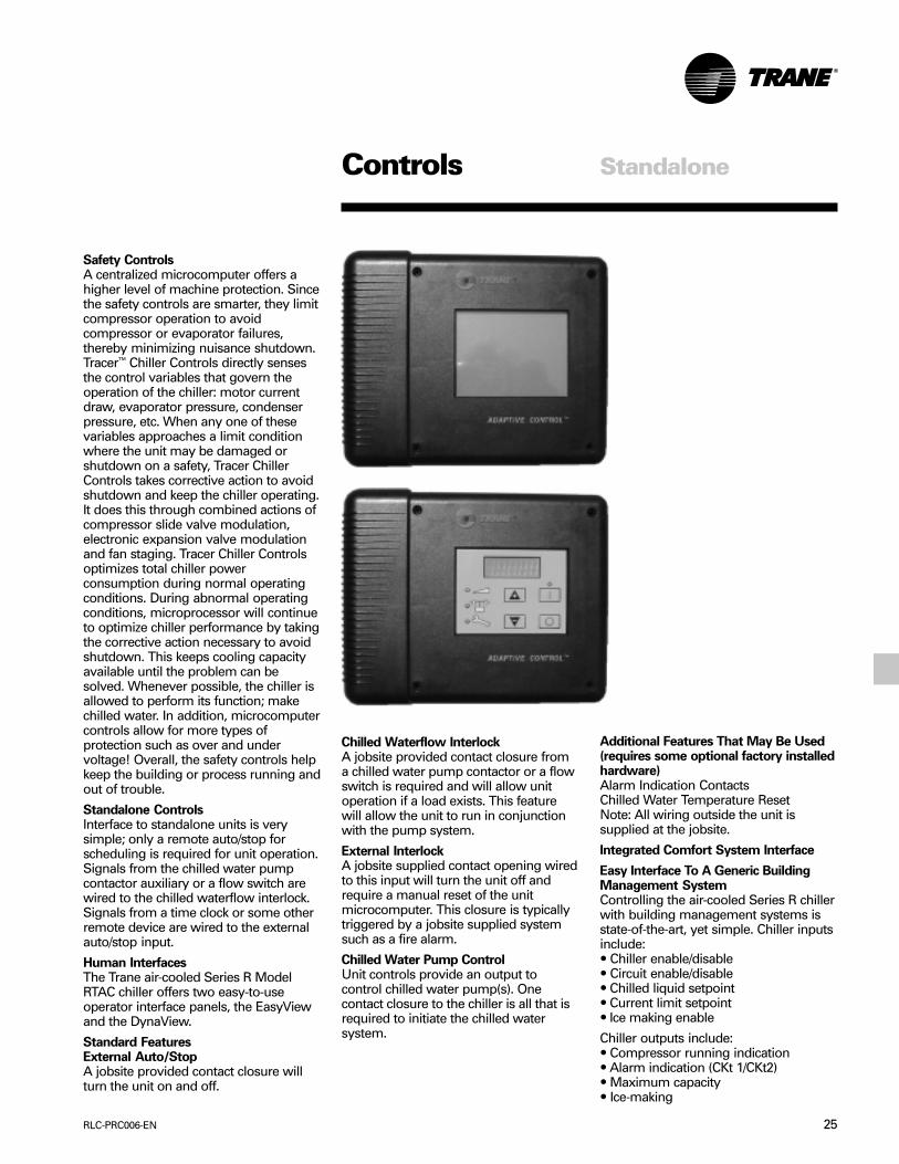
Human InterfacesThe Trane air-cooled Series R ModelRTAC chiller offers two easy-to-useoperator interface panels, the EasyViewand the DynaView.
Standard FeaturesExternal Auto/StopA jobsite provided contact closure willturn the unit on and off.
Controls
Chilled Waterflow InterlockA jobsite provided contact closure froma chilled water pump contactor or a flowswitch is required and will allow unitoperation if a load exists. This featurewill allow the unit to run in conjunctionwith the pump system.
External InterlockA jobsite supplied contact opening wiredto this input will turn the unit off andrequire a manual reset of the unitmicrocomputer. This closure is typicallytriggered by a jobsite supplied systemsuch as a fire alarm.
Chilled Water Pump ControlUnit controls provide an output tocontrol chilled water pump(s). Onecontact closure to the chiller is all that isrequired to initiate the chilled watersystem.
Standalone
Additional Features That May Be Used(requires some optional factory installedhardware)Alarm Indication ContactsChilled Water Temperature ResetNote: All wiring outside the unit issupplied at the jobsite.
Integrated Comfort System Interface
Easy Interface To A Generic BuildingManagement SystemControlling the air-cooled Series R chillerwith building management systems isstate-of-the-art, yet simple. Chiller inputsinclude:• Chiller enable/disable• Circuit enable/disable• Chilled liquid setpoint• Current limit setpoint• Ice making enable
Chiller outputs include:• Compressor running indication• Alarm indication (CKt 1/CKt2)• Maximum capacity• Ice-making
RLC-PRC006-EN26
Generic BuildingAutomation SystemControls
Simple Interface With Other ControlSystemsMicrocomputer controls afford simpleinterface with other control systems,such as time clocks, building automationsystems and ice storage systems. Thismeans you can have the flexibility tomeet job requirements while not havingto learn a complicated control system.This setup has the same standardfeatures as a stand-alone water chiller,with the possibility of having thefollowing optional features.
Alarm Indication ContactsThe unit provides three single-pole/double-throw contact closures toindicate that a failure has occurred, if anycompressors are running, or if thecompressors are running at maximumcapacity. These contact closures may beused to trigger jobsite supplied alarmlights or alarm bells.
External Chilled Water SetpointAllows the external setting independentof the front panel setpoint by one of twomeans:a) 2-10 VDC input, orb) 4-20 mA input.
External Current Limit SetpointAllows the external setting independentof the front panel set point by one of twomeans:a) 2-10 VDC input, orb) 4-20 mA input.
Ice Making ControlProvides interface with ice makingcontrol systems.
Chilled Water Temperature ResetReset can be based on return watertemperature or outdoor air temperature.
Tracer Summit controls — Interface WithThe Trane Integrated Comfort System(ICS)
Trane Chiller Plant Manager/ICSThe Tracer Chiller Plant ManagerBuilding Management System providesbuilding automation and energymanagement functions through stand-alone control. The Chiller Plant Manageris capable of monitoring and controllingyour entire chiller plant system.
Application software available:• Time-of-day scheduling• Duty cycle• Demand limiting• Chiller sequencing• Process control language• Boolean processing• Zone control• Reports and logs• Custom messages• Run time and maintenance• Trend log• PID control loops
And of course, the Trane Chiller PlantManager Panel can be used on a stand-alone basis or tied into a completebuilding automation system.
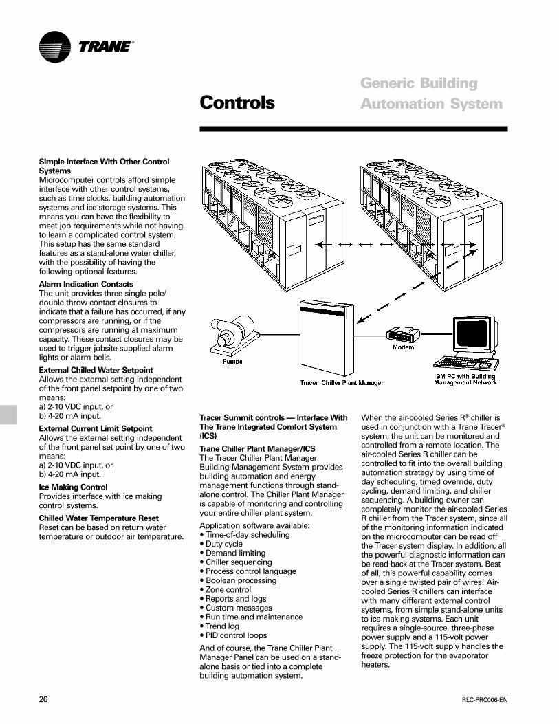
When the air-cooled Series R® chiller isused in conjunction with a Trane Tracer®
system, the unit can be monitored andcontrolled from a remote location. Theair-cooled Series R chiller can becontrolled to fit into the overall buildingautomation strategy by using time ofday scheduling, timed override, dutycycling, demand limiting, and chillersequencing. A building owner cancompletely monitor the air-cooled SeriesR chiller from the Tracer system, since allof the monitoring information indicatedon the microcomputer can be read offthe Tracer system display. In addition, allthe powerful diagnostic information canbe read back at the Tracer system. Bestof all, this powerful capability comesover a single twisted pair of wires! Air-cooled Series R chillers can interfacewith many different external controlsystems, from simple stand-alone unitsto ice making systems. Each unitrequires a single-source, three-phasepower supply and a 115-volt powersupply. The 115-volt supply handles thefreeze protection for the evaporatorheaters.
27RLC-PRC006-EN
Controls
A single twisted pair of wires tied directlybetween the air-cooled Series R® chillerand a Tracer® system provides control,monitoring and diagnostic capabilities.Control functions include auto/stop,adjustment of leaving water temperatureset point, compressor operation lockoutfor kW demand limiting and control ofice making mode. The Tracer systemreads monitoring information such asentering and leaving evaporator watertemperatures and outdoor airtemperature. Over 60 individualdiagnostic codes can be read by the InTracer system. In addition, the Tracersystem can provide sequencing controlfor two to six units on the same chilledwater loop. Pump sequencing controlcan be provided from the Tracer system.Tracer ICS is not available in conjunctionwith the remote display or the externalset point capability.
Required Options
1Tracer Comm 3 Interface
Additional Options That May Be UsedIce Making Control
External Trane Devices RequiredTracer Summit® , Tracer 100 System orTracer Chiller Plant Manager
Ice Making Systems ControlsAn ice making option may be orderedwith the air-cooled Series R® chiller. Theunit will have two operating modes, icemaking and normal daytime cooling. Inthe ice making mode, the air-cooledSeries R chiller will operate at fullcompressor capacity until the returnchilled fluid temperature entering theevaporator meets the ice making setpoint. This ice making set point ismanually adjusted on the unit’smicrocomputer. Two input signals arerequired to the air-cooled Series R chillerfor the ice making option. The first is anauto/stop signal for scheduling and thesecond is required to switch the unit inbetween the ice making mode andnormal daytime operation. The signalsare provided by a remote job sitebuilding automation device such as atime clock or a manual switch. Inaddition, the signals may be providedover the twisted wire pair from a Tracer®
system. Units from 130- 400 tons do notprovide outputs to turn water pumps onand off.
Required OptionsExternal Auto/Stop (Standard)
Trane ICS Controls

RLC-PRC006-EN28
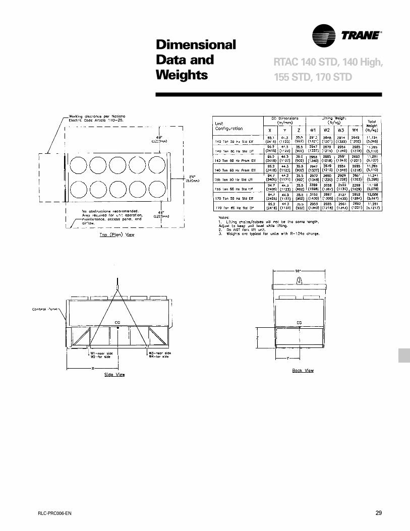
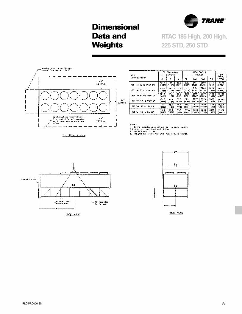
DimensionalData andWeights
RTAC 140 STD, 140 High,
155 STD, 170 STD
29RLC-PRC006-EN
DimensionalData andWeights
RTAC 140 STD, 140 High,
155 STD, 170 STD
RLC-PRC006-EN30
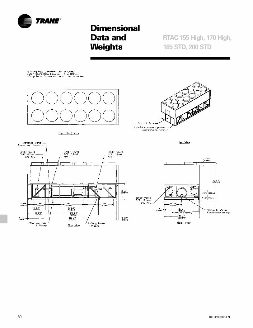
DimensionalData andWeights
RTAC 155 High, 170 High,
185 STD, 200 STD
31RLC-PRC006-EN
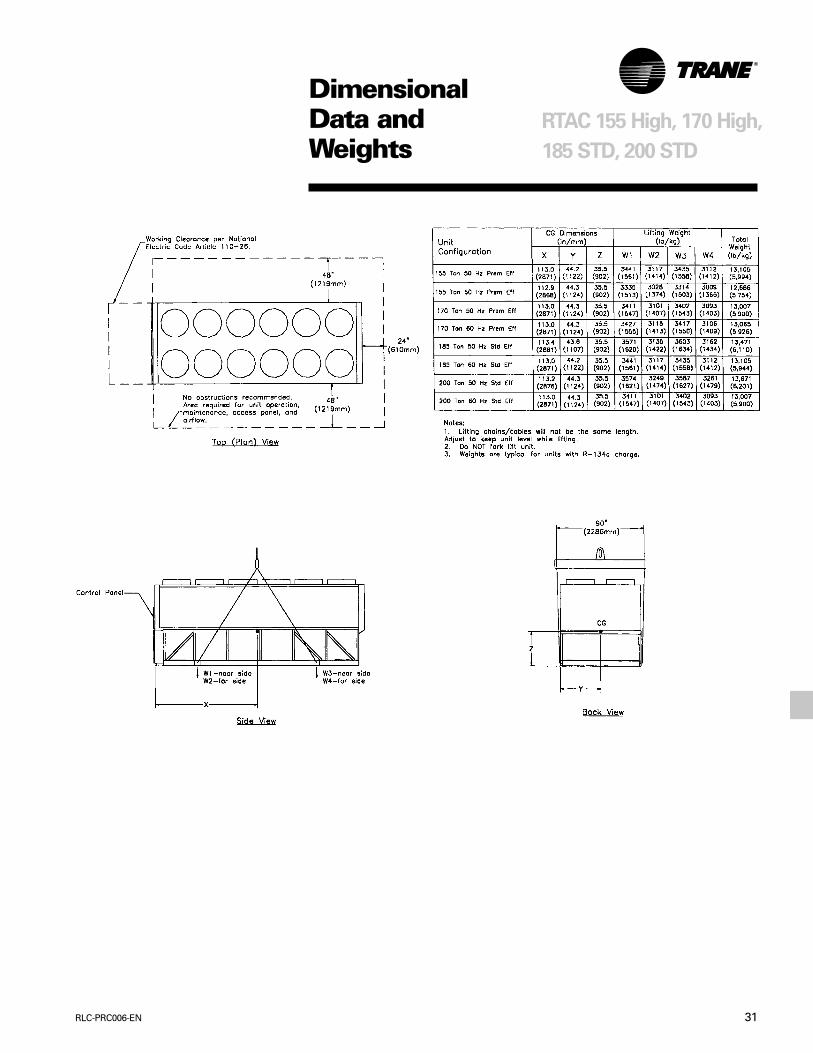
DimensionalData andWeights
RTAC 155 High, 170 High,
185 STD, 200 STD
RLC-PRC006-EN32
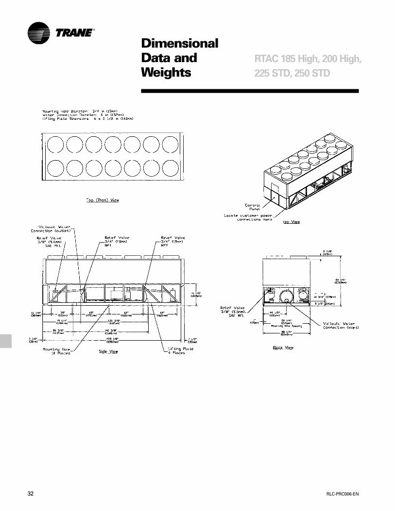
DimensionalData andWeights
RTAC 185 High, 200 High,
225 STD, 250 STD
33RLC-PRC006-EN
DimensionalData andWeights
RTAC 185 High, 200 High,
225 STD, 250 STD
RLC-PRC006-EN34
GeneralUnits are leak and pressure tested at 350psig high side, 200 psig low side, thenevacuated and charged. Packaged unitsship with a full operating charge of oiland refrigerant. Unit panels, structuralelements and control boxes areconstructed of 12-gauge galvanized steeland mounted on a welded structuralsteel base. Unit panels and control boxesare finished with a baked on powderpaint, and the structural base with an airdry paint. All paint meets therequirement for outdoor equipment ofthe U.S. Navy and other federalgovernment agencies.
EvaporatorThe evaporator is a tube-in-shell heatexchanger design with internally finnedcopper tubes roller expanded into thetube sheet. The evaporator is designed,tested and stamped in accordance withASME for a refrigerant side workingpressure of 200 psig. The evaporator isdesigned for a water side workingpressure of 150 psig. Water connectionsare grooved pipe. Each shell includes avent, a drain and fittings for temperaturecontrol sensors and is insulated with3/4-inch Armaflex II or equal insulation(K=0.26). Evaporator heaters withthermostat are provided to protect theevaporator from freezing at ambienttemperatures down to -20 F.
Condenser and FansAir-cooled condenser coils havealuminum fins mechanically bonded tointernally finned seamless coppertubing. The condenser coil has anintegral subcooling circuit. Condensersare factory proof and leak tested at 440psig. Direct-drive vertical dischargecondenser fans are dynamicallybalanced. Three-phase condenser fansmotors with permanently lubricated ballbearing and internal thermal overloadprotection are provided. Standard unitswill start and operate between of 25 to115°F/4 to 46°C ambient.
MechanicalSpecifications
Compressor and Lube Oil SystemThe rotary screw compressor is semi-hermetic, direct drive, 3600 rpm, withcapacity control slide valve, a load/unload valve, rolling element bearings,differential refrigerant pressure oil pumpand oil heater. The motor is a suction gascooled, hermetically sealed, two-polesquirrel cage induction motor. Oilseparator and filtration devices areprovided separate from the compressor.Check valves in the compressordischarge and lube oil system and asolenoid valve in the lube system areprovided.
Refrigeration CircuitsEach unit has two refrigerant circuits,with one rotary screw compressor percircuit. Each refrigerant circuit includes acompressor discharge service valve,liquid line shutoff valve, removable corefilter, liquid line sight glass with moistureindicator, charging port and an electronicexpansion valve. Fully modulatingcompressors and electronic expansionvalves provide variable capacitymodulation over the entire operatingrange.
Unit ControlsAll unit controls are housed in aweathertight enclosure with removableplates to allow for customer connectionof power wiring and remote interlocks.All controls, including sensors, arefactory mounted and tested prior toshipment. Microcomputer controlsprovide all control functions includingstart-up and shut down, leaving chilledwater temperature control, compressorand electronic expansion valvemodulation, fan sequencing, antirecyclelogic, automatic lead/lag compressorstarting and load limiting. The unitcontrol module, utilizing AdaptiveControl™ microprocessor, automaticallytakes action to avoid unit shutdown dueto abnormal operating conditionsassociated with low refrigerant pressure,high condensing pressure and motorcurrent overload. Should the abnormaloperating condition continue until a
protective limit is violated, the unit willbe shut down. Unit protective functionsinclude loss of chilled water flow,evaporator freezing, loss of refrigerant,low refrigerant pressure, high refrigerantpressure, reverse rotation, compressorstarting and running over current, phaseloss, phase imbalance, phase reversal,and loss of oil flow. A digital displayindicates chilled water setpoint andleaving chilled water temperature asstandard. While current limit setpoint,evaporator and condenser refrigerantpressures, and electrical information arean option. Both standard and optionaldisplays can be viewed on the unitwithout opening any control paneldoors. Standard power connectionsinclude main three phase power to thecompressors, condenser fans andcontrol power transformer and optionalconnections are available for the 115 voltsingle phase power for freeze protectionon the evaporator heaters.
StartersStarters are housed in a weathertightenclosure with removable cover plate toallow for customer connection of powerwiring. Across-the-line starters arestandard on all 380-575 volt units. WyeDelta closed transition starters (33percent of LRA inrush) are optional on380-575 volt units. Typically, Trane helicalrotary screw compressors are up to fullspeed in one second when startedacross-the-line and have equivalentinrush with similar size reciprocatingcompressor with part wind starters.

35RLC-PRC006-EN
The Trane CompanyAn American Standard Companywww.trane.com
For more information contactyour local district office ore-mail us at [email protected]
Since The Trane Company has a policy of continuous product improvement, it reserves the right to changedesign and specifications without notice.
Literature Order Number
File Number
Supersedes
Stocking Location
RLC-PRC006-EN
PL-RF-RLC-000-PRC006-0900
New
La Crosse