trane rotary screw air cooled chiller 100 ton mfg: trane model
TRANSCRIPT
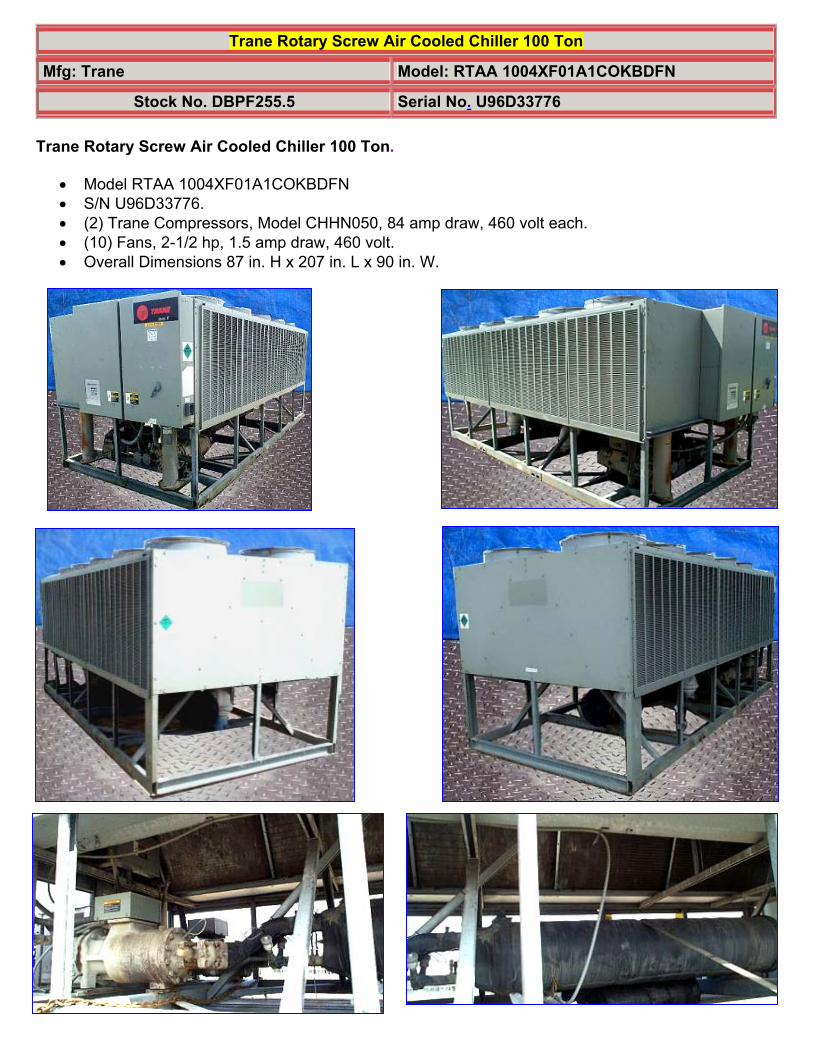
Trane Rotary Screw Air Cooled Chiller 100 Ton
Mfg: Trane Model: RTAA 1004XF01A1COKBDFN
Stock No. DBPF255.5 Serial No. U96D33776 Trane Rotary Screw Air Cooled Chiller 100 Ton.
• Model RTAA 1004XF01A1COKBDFN • S/N U96D33776. • (2) Trane Compressors, Model CHHN050, 84 amp draw, 460 volt each. • (10) Fans, 2-1/2 hp, 1.5 amp draw, 460 volt. • Overall Dimensions 87 in. H x 207 in. L x 90 in. W.


Air-Cooled Series R™
Rotary Liquid Chiller
Model RTAA
70 to 125 Tons
Built for the Industrial and Commercial Markets
RLC-PRC016-ENAugust 2002

RLC-PRC016-EN2
Features andBenefits
You…Like its chillers, Trane wants itsrelationships with customers to last.Trane is interested in maintaining longterm, loyal relationships. Thisperspective means the point in time thata customer purchases a chiller is thebeginning of a relationship, not the end.Your business is important, but yoursatisfaction is paramount.
Designed by Customers….Trane’s RTAA 70-125 was designed withthe end user’s requirements in mind.Reliability, efficiency, sound, andphysical size were primary designconcerns in expanding the RTAA productline down to 70 tons. The result is areliable chiller that will help you achieveyour bottom line goals.
© 2002 American Standard Inc. All rights reserved.

3RLC-PRC016-EN
Contents
Features and Benefits
Model Number Description
General Data
Selection Procedure
Application Considerations
Performance Adjustment Factors
Performance Data
Electrical Data
Jobsite Connections
Controls
Dimensional Data
Weights
Options
Typical Wiring Diagrams
Features Summary
Mechanical Specifications
2
13
14
15
16
20
22
29
30
32
40
41
42
43
45
46
The standard ARI rating condition(54/44°F and 95°F) and IPLV are ARIcertified. All other ratings, including thefollowing, are outside the scope of thecertification program and are excluded:• Glycol.• 50 Hz.• Remote evaporator models.
Water Chiller Systems Business Unit

RLC-PRC016-EN4
Features andBenefits
ImprovementsThe RTAA 70-125 offers the same highreliability of its larger predecessorcoupled with lowered sound levels,increased energy efficiency, and reducedphysical footprint, all due to its advanceddesign, low speed/direct drivecompressor and proven Series R™
performance.
Some of the major advantages of theModel RTAA 70-125 vs its largerpredecessor are:• Higher energy efficiency• Lower sound levels• Smaller physical footprint
The Series R™ Model RTAA 70-125 is anindustrial grade design built for both theindustrial and commercial markets. It isideal for schools, hospitals, retailers,office buildings, Internet serviceproviders and industrials.
ASHRAE Standard 90.1 and RTAA 70-125 World Class Energy Efficiency…The importance of energy efficiencycannot be understated. Fortunately,ASHRAE has created a guidelineemphasizing its importance.Nonetheless, energy is often dismissedas an operational cost over which theowner has little control. That perceptionresults in missed opportunities forenergy efficiency, reduced utility bills,and higher profits. Lower utility billsdirectly affect profitability. Every dollarsaved in energy goes directly to thebottom line. Trane’s RTAA 70-125 is oneway to maximize your profits.
ASHRAE Standard 90.1 & ExecutiveOrder - New technology applied to thedesign, controls, and manufacturinghave created superior efficiency levels inthe RTAA 70-125 that are unmatched inthe industry. All Trane air-cooled chillersmeet the new efficiency levels mandatedby ASHRAE Standard 90.1. This newstandard requires higher efficienciesthan past technologies can deliver. TheUS Federal Government has adoptedstandard 90.1 and, in some cases,requires even higher efficiencies.Federal Executive Order mandatesenergy consuming devices procuredmust be in the top 25% of their class or
be at least 10% better than any productstandard for that product. In the case ofchillers, that product standard isASHRAE 90.1. Trane’s RTAA 70-125meets and exceeds the efficiencyrequirements of 90.1, with some unitsmeeting the “stretch goals” of ExecutiveOrder.
Risk. The US Federal Government hasadopted ASHRAE 90.1, and it’s expectedto be adopted domestically, if notglobally, in the future. Domesticacceptance has already begun. Makesure that your chillers as well as yourentire HVAC system complies, or youmay be caught retrofitting your projectwith new equipment and paying extradesign dollars if the code is adoptedduring construction.
Precise Capacity Control. Trane’spatented unloading system allows thecompressor to modulate infinitely andexactly match building loads. At thesame time chilled water temperatureswill be maintained within +/- 1/2ºF of
setpoint, potentially eliminating the needfor external considerations to maintaintemperatures. Reciprocating and screwchillers with stepped capacity control dowell to maintain chilled watertemperatures within 2ºF of setpoint.Stepped control also results inovercooling or undercooling your spacebecause rarely does the capacity of themachine match the building load. Theresult can be 10% higher energy bills.Trane’s RTAA optimizes the part loadperformance of your machine for energyefficiency, precise temperature controlfor all modes of operation, and yourpersonal comfort regardless of changingconditions.

5RLC-PRC016-EN
Features andBenefits
Excellent Reliability
A building environment is expected tobe comfortable. When it is, no one saysa word. If it’s not… that’s a differentstory. The same is true with chillers. Noone ever talks about chillers, yet alonecompressors, until they fail, and tenetsare uncomfortable and productivity islost. Trane’s helical rotary compressorshave a first year reliability rate of over99%, which means our chillers stayrunning when you need them.
Screw compressors were designed toreplace the inherent design flaws of areciprocating compressor. Trane’s helicalrotary compressor has successfullyachieved this goal, proven by the over99% reliability rating of our compressorin the first year of operation. A gooddesign like Trane’s should maintain thislevel of reliability for several years ofchiller operation. Not all screwcompressors maintain a high reliabilityand Trane is the only manufacturer thatwill publish a reliability number. Thepoint is to make sure that you are gettinga reliable screw chiller design so that youdon’t end up with the downtime and lostearnings that the industry is trying to
avoid by getting away fromreciprocating technology.
Fewer moving parts. Trane’s helicalrotary compressors have only two majorrotating parts: the male and female rotor.A reciprocating compressor can havemore than 15 times that number ofcritical parts. Multiples of pistons,valves, crankshafts, and connecting rodsin a reciprocating unit all representdifferent failure paths for thecompressor. In fact, reciprocatingcompressors can easily have a failurerate four times that of a helical rotor.Combine this with two to threereciprocating compressors for eachhelical rotary compressor on chillers ofequal tonnage, and statistics tell you it’s
a matter of time before you lose areciprocating compressor.
Robust parts. Helical rotarycompressors are precisely machinedusing state of the art processes fromsolid metal bar stock. Tolerances aremaintained within a micron or less thana tenth of the diameter of a human hair.The resulting compressor is a robust yethighly sophisticated assembly capable ofingesting liquid refrigerant without riskof damage. Contrast this to areciprocating compressor, which can bedestroyed by a single slug of liquid.
Series R™ Compressor Highlights• Direct-drive, low speed for high
efficiency and reliability.• Simple design with only four moving
parts, resulting in high reliability andlow maintenance.
• Field serviceable compressor for easymaintenance.
• Precise rotor tip clearance for optimalefficiency.
• Suction gas-cooled motor, resulting inlower operating temperatures forincreased motor life, and giving thecapability for:
• Five-minute start-to-start/two minutestop-to-start capability, which allowsfor closer water loop temperaturecontrol.

RLC-PRC016-EN6
Features andBenefits
RTAA 70-125 Chiller Highlights• High Reliability, with over 99%
compressor reliability rate in the firstyear of operation, and AdaptiveControls to keep the chiller on lineproducing cold water during adverseconditions.
• High Efficiency (all units exceedASHRAE 90.1 efficiency standard).
• Low sound levels.• Small footprint, with smallest required
application space (operating footprint)in the industry.
• Years of research, testing, andsuccessful applications. The Tranehelical rotary compressor has amassedthousands of hours of testing, much ofit at severe operating conditions. Notto mention the successful applicationof RTAA chillers for over 11 years, witha developed reputation as the industrystandard.
• Trouble free startup through factorytesting of compressor and completedchiller and factory installation of chilleraccessories.
• +/- ½°F leaving water temperaturecontrol, resulting from PID feed-forward controls, and linear loadmatching, also allowing for 10% flowrate change per minute whilemaintaining ± ½°F leaving watertemperature control.
Trane helical rotary screw compressorcomponent parts versus reciprocatingcompressor components.

7RLC-PRC016-EN
Features andBenefits
Superior Full Load Efficiency
Precise Rotor Tip ClearancesHigher energy efficiency in a helicalrotary compressor is obtained byreducing the rotor tip clearances. Thisreduces the leakage between high andlow pressure cavities duringcompression. Precise rotor tip clearanceis achieved with the latest manufacturingand machining technology. Trane is thefirst helical rotary compressormanufacturer to electronically checkcompressor parts machining accuracy aspart of the standard production process.
Optimized Compressor Parts ProfilesRotor and slide valves are uniquedesigns, optimized for the airconditioning application. The rotors aredesigned for the pressure ranges in theair conditioning application. The unloadervalve has a unique profile that resultedfrom computer performance modeling intypical part-load situations.
Advanced Heat Transfer SurfacesCondenser and evaporator tubes use thelatest heat transfer technology forincreased efficiency.
Great Part Load EfficiencyWith Trane Helical RotaryScrew Compressors andElectronic Expansion Valve
Trane Helical Rotary Screw CompressorMeans Superior Part Load PerformanceThe air-cooled Series R™ chiller has greatpart-load performance. The combinationpatented unloading system on the“general purpose” compressor utilizesthe variable unloading valve for themajority of the unloading functionsimilar to that of the slide valve. The“general purpose” compressor alsouses a step unloader valve which is asingle unloading step to achieve theminimum unloading point of thecompressor. The result of both of thesedesigns is optimized part-loadperformance far superior to singlereciprocating compressors.
OptimumEfficiencies

RLC-PRC016-EN8
Features andBenefits
Electronic Expansion ValveWhen coupled with Trane’s AdaptiveControl™ microprocessor, our electronicexpansion valve significantly improvespart-load performance of the Series R™
chiller by minimizing superheat in theevaporator and allowing the chiller torun at reduced condensingtemperatures. Chillers which useconventional TXV’s must run at higherhead pressures and consume morepower than necessary at part-loads.Additionally, the electronic expansionvalve and its controls allow much betterstability and control over dynamic loadand head changes. Under theseconditions a conventional TXV maynever achieve control stability andextended periods of TXV “hunting” andliquid slugging are common.
Capacity Control and Load MatchingInfinitely variable compressormodulation allows the compressorcapacity to exactly match the buildingcooling load. Reciprocating and screwchillers that rely on stepped capacitycontrol must run at a capacity equal to orgreater than the load. Much of thisexcess capacity is lost becauseovercooling goes toward building latentheat removal, causing the building to bedried beyond normal comfortrequirements. The result is an increase inchiller energy costs, particularly at thepart-load conditions at which the chilleroperates most of the time.
PID Chilled Water SetpointControl Through Slide ValveModulation
Maintain Chilled Water Supply Within± 1/2°F of SetpointChillers that have step capacity controltypically can only maintain watertemperature to around ± 2°F. With theair-cooled Series R™ chiller, maintainingtemperature control has never been soaccurate.
Reduce Compressor CyclingModulating capacity control offers bettercompressor reliability. Compressorcycling, typical of reciprocatingcompressors, will decrease compressorcomponent life. Parts like motors andvalves do not stand up well to excessivecompressor cycling.
Cutaway view of Trane’s electronic expansion valve.

9RLC-PRC016-EN
Features andBenefits
Trouble-Free Installation,Start-Up and Operation
Adaptive Control™ MicroprocessorThe RTAA 70-125 chiller offers advancedmicroprocessor control and features theAdaptive Control microprocessor. Sowhat is the Adaptive Controlmicroprocessor? Adaptive Controlmeans the Unit Control Module (UCM)directly senses the control variables thatgovern operation of the chiller: motorcurrent draw, evaporator temperature,condenser temperature, etc.
When any of the variables approaches alimit condition where the unit may bedamaged or shut down on a safety, theUCM takes corrective action to avoid
shutdown and keep the chiller operating.It does this through combined actions ofcompressor slide valve modulation,electronic expansion valve modulationand fan staging. Additionally, the UCMoptimizes total unit power consumptionduring normal operating conditions. Noother chiller control system in themarketplace duplicates thisperformance.
The End Of Most Nuisance Trip-OutsAnd Unnecessary Service Calls?Unnecessary service calls and unhappytenants are reduced. Only when theUCM has exhausted the correctiveactions it can take and the unit is stillviolating an operating limit will the unitshut down. CONTROLS ON OTHER
CHILLERS TYPICALLY SHUT DOWN THECHILLER, QUITE PROBABLY JUSTWHEN IT IS NEEDED THE MOST.
For example:A typical five-year-old chiller with dirtycoils might trip-out on high pressurecutout on a 100°F day in August. A hotday is just when comfort cooling isneeded the most. In contrast, the air-cooled Series R™ chiller with an AdaptiveControl microprocessor will stage fanson, modulate electronic expansion valve,and modulate slide valve as itapproaches a high pressure cutout.Thereby KEEPING THE CHILLER ON-LINE JUST WHEN YOU NEED IT THEMOST.

RLC-PRC016-EN10
Close Spacing Of ChillerThe air-cooled Series R™ chiller has thetightest recommended side clearance inthe industry, four feet, but that is not all.In situations where equipment must beinstalled with less clearance thanrecommended, such as frequentlyoccurs in retrofit and rooftopapplications, restricted air flow iscommon. Conventional chillers may notwork at all. However, the air-cooledSeries R™ chiller with Adaptive Control™microprocessor will simply make asmuch chilled water as it can given theactual installed conditions, stay on lineduring any unforeseen abnormalconditions, and optimize itsperformance. Consult your Trane salesengineer for more details.
Lower Service ExpenseNuisance service calls are avoided.When there is a real problem that mustbe corrected, the UCM’s extensivediagnostics help assure that the problemis quickly identified. Down time andservice expense are minimized. And withthe ability to communicate with theTrane Integrated Comfort™ system or aremote display panel, service problemscan be identified and diagnosed remoteto the installation.
Factory Testing Means Trouble-FreeStart-UpAll air-cooled Series R™ chillers are givena complete functional test at the factory.This computer-based test programcompletely checks the sensors, wiring,electrical components, microprocessorfunction, communication capability,expansion valve performance and fans.In addition, each compressor is runtested to verify capacity and powerconsumption. The end result of this testprogram is that the chiller arrives at thejobsite fully tested and ready to go towork.
Factory Installed And Tested Controls/Options Speed InstallationAll Series R™ chiller options, includingcontrol power transformer, starterdisconnect, low ambient control,ambient temperature sensor, lowambient lockout, communicationinterface and ice making controls arefactory installed and tested. Somemanufacturers send options in pieces tobe field installed. With Trane, thecustomer saves on installation expenseand has assurance that ALL chillercontrols/options have been tested andwill function as expected.
Features andBenefits

11RLC-PRC016-EN
Features andBenefits
Superior Control
Unit Control ModuleTrane’s Adaptive Control™microprocessor control system enhancesthe air-cooled Series R™ chiller byproviding the very latest chiller controltechnology.
State-of-the-Art EquipmentThe 70 to 125 ton air-cooled chillers offerthe exclusive Trane Adaptive Controllogic with the Clear Language Display(UCM). The Clear Language Display hasvarious functions that allow the operatorto read unit information and adjustsetpoints. The Clear Language Displaypanel has 16 keys, the readout screen is atwo-line, 40 character liquid crystal with abacklight. The backlight allows theoperator to read the display in low-lightconditions.
Unit Control Module Features
Equal Compressor SequencingTrane maximizes both compressor andmotor life by equalizing both the numberof starts and the operating hours. TheUCM will start the compressor with theleast number of starts and turn off thecompressor with the most operatinghours. Conventional “auto” lead-lagcontrol will equalize starts, but runninghours will typically be unequal.Equalizing both starts and running hourswill provide equal compressor wear.
Internal “Built-In” Chiller FlowProtectionThe UCM automatically detects a nowaterflow condition. An external flowswitch is not required, which lowerscosts versus typical chillers. Built-in flowprotection also eliminates nuisance flowswitch problems.
Remote Clear Language Display Panelfor 70 to 125-ton air-cooled chillers.
RLC-PRC016-EN12
Easy Chiller System LoggingThe UCM displays data required to logthe chiller system. The followinginformation is available either asstandard or as an option with the Air-Cooled Series R™ Chiller microprocessor:• Entering and leaving chilled water
temperatures• Ambient air temperature• Evaporator and condenser refrigerant
temperatures and pressures• Compressor suction temperature• Percent RLA for each compressor• Percent line voltage• Compressor starts and running hours• Active setpoints:
chilled water setpointcurrent limit setpointice termination setpointlow ambient lockout setpoint
• Over 90 diagnostic and operatingconditions
• Part failure diagnostics:water temperature sensorsrefrigerant temperature sensorscompressor contactors
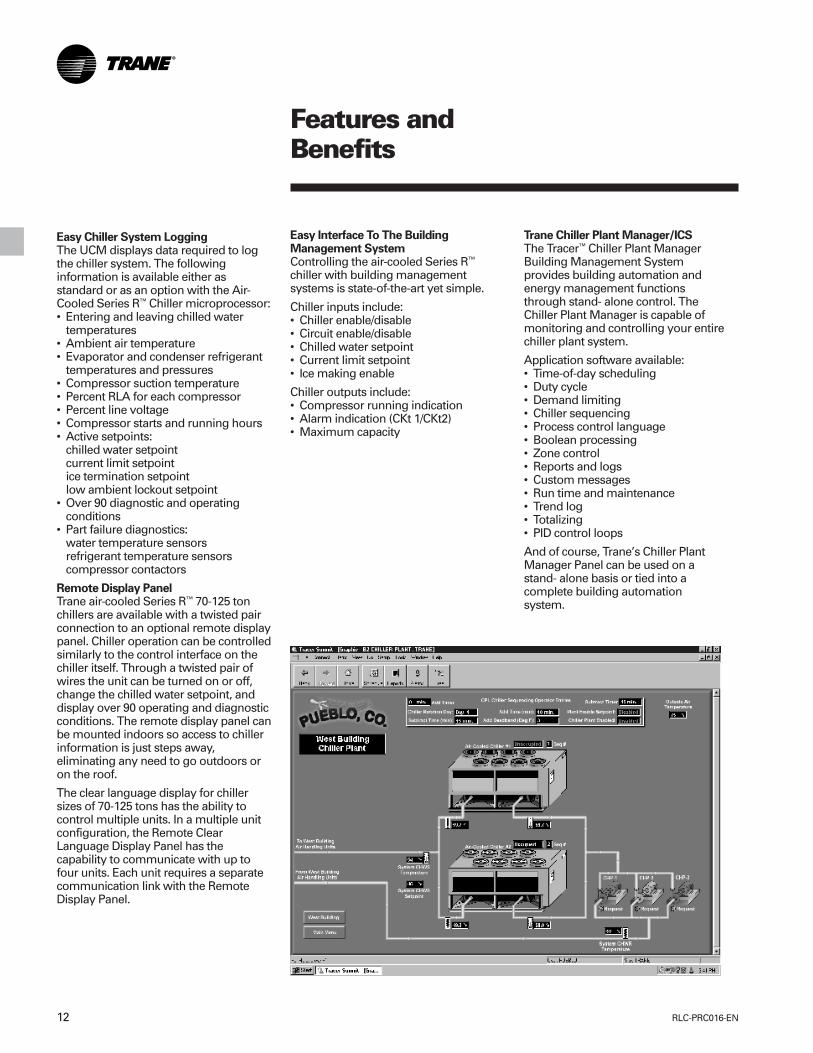
Remote Display PanelTrane air-cooled Series R™ 70-125 tonchillers are available with a twisted pairconnection to an optional remote displaypanel. Chiller operation can be controlledsimilarly to the control interface on thechiller itself. Through a twisted pair ofwires the unit can be turned on or off,change the chilled water setpoint, anddisplay over 90 operating and diagnosticconditions. The remote display panel canbe mounted indoors so access to chillerinformation is just steps away,eliminating any need to go outdoors oron the roof.
The clear language display for chillersizes of 70-125 tons has the ability tocontrol multiple units. In a multiple unitconfiguration, the Remote ClearLanguage Display Panel has thecapability to communicate with up tofour units. Each unit requires a separatecommunication link with the RemoteDisplay Panel.
Easy Interface To The BuildingManagement SystemControlling the air-cooled Series R™
chiller with building managementsystems is state-of-the-art yet simple.
Chiller inputs include:• Chiller enable/disable• Circuit enable/disable• Chilled water setpoint• Current limit setpoint• Ice making enable
Chiller outputs include:• Compressor running indication• Alarm indication (CKt 1/CKt2)• Maximum capacity
Trane Chiller Plant Manager/ICSThe Tracer™ Chiller Plant ManagerBuilding Management Systemprovides building automation andenergy management functionsthrough stand- alone control. TheChiller Plant Manager is capable ofmonitoring and controlling your entirechiller plant system.
Application software available:• Time-of-day scheduling• Duty cycle• Demand limiting• Chiller sequencing• Process control language• Boolean processing• Zone control• Reports and logs• Custom messages• Run time and maintenance• Trend log• Totalizing• PID control loops
And of course, Trane’s Chiller PlantManager Panel can be used on astand- alone basis or tied into acomplete building automationsystem.
Features andBenefits

13RLC-PRC016-EN
Model NumberDescription
Model Nomenclature Digit Number
1 2 3 4 5 6 7 8 9 10 11 12 13 14 15 16 17
70-125 Tons
Digits 1,2 — Unit ModelRT = Rotary Chiller
Digit 3 — Unit TypeA = Air Cooled
Digit 4 — Development SequenceA = First Sequence
Digit 5, 6 & 7 — Nominal Capacity070 = 70 tons080 = 80 tons090 = 90 tons100 = 100 tons110 = 110 tons125 = 125 tons
Digit 8 — Unit VoltageA = 200/60/3C = 230/60/3D = 380/60/34 = 460/60/35 = 575/60/3S = Special
Digit 9 — Compressor Starter TypeY = Y-Delta Closed TransitionX = X-Line (Across the Line)S = Special
Digit 10, 11 — Design Sequence** = Factory Input
Digit 12 — Evaporator Leaving Temperature1 = Standard 40 to 65°F2 = Low 0 to 39°F3 = Ice-Making 20 to 65°FS = Special
Digit 13 — Condenser Coil Fin MaterialA = AluminumS = Special2 = Copper Fins4 = CompleteCoat
Digit 14 — Agency Listing0 = No Agency Listing3 = C/UL Listing
Digit 15 — Control InterfaceC = Deluxe without CommunicationD = Deluxe with Communication
Digit 16 — Chilled Water Reset0 = No Chilled Water Reset1 = Based on Return Water Temperature2 = Based on Outside Air Temperature
Digit 17 — Miscellaneous Factory InstalledOptions
A = Architectural Louvered PanelsB = Control Power TransformerC = Convenience OutletD = Low Ambient Lockout SensorF = Mech. Disconnect SwitchG = Low Ambient OperationK = Coil ProtectionM = Access GuardP = Circuit Breaker (Single Point Power)Z = Circuit Breaker (Dual Point Power)
Field Installed OptionsQ = Spring IsolatorsN = Neoprene IsolatorsR = Remote Display Panel3 = 5 Year Compressor Warranty8 = Architectural Louvered Panels9 = Coil Protection0 = Access GuardJ = Remote EvaporatorH = Sound Attenuator
RLC-PRC016-EN14
General Data
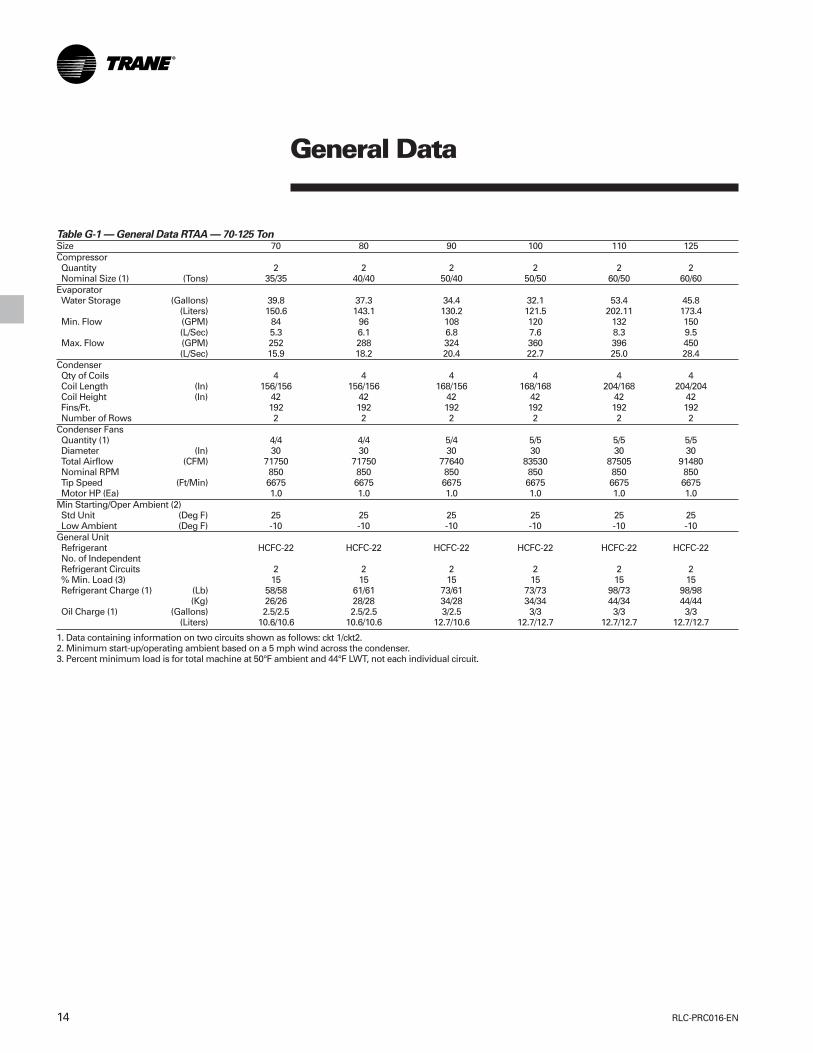
Table G-1 — General Data RTAA — 70-125 TonSize 70 80 90 100 110 125Compressor Quantity 2 2 2 2 2 2 Nominal Size (1) (Tons) 35/35 40/40 50/40 50/50 60/50 60/60Evaporator Water Storage (Gallons) 39.8 37.3 34.4 32.1 53.4 45.8
(Liters) 150.6 143.1 130.2 121.5 202.11 173.4 Min. Flow (GPM) 84 96 108 120 132 150
(L/Sec) 5.3 6.1 6.8 7.6 8.3 9.5 Max. Flow (GPM) 252 288 324 360 396 450
(L/Sec) 15.9 18.2 20.4 22.7 25.0 28.4Condenser Qty of Coils 4 4 4 4 4 4 Coil Length (In) 156/156 156/156 168/156 168/168 204/168 204/204 Coil Height (In) 42 42 42 42 42 42 Fins/Ft. 192 192 192 192 192 192 Number of Rows 2 2 2 2 2 2Condenser Fans Quantity (1) 4/4 4/4 5/4 5/5 5/5 5/5 Diameter (In) 30 30 30 30 30 30 Total Airflow (CFM) 71750 71750 77640 83530 87505 91480 Nominal RPM 850 850 850 850 850 850 Tip Speed (Ft/Min) 6675 6675 6675 6675 6675 6675 Motor HP (Ea) 1.0 1.0 1.0 1.0 1.0 1.0Min Starting/Oper Ambient (2) Std Unit (Deg F) 25 25 25 25 25 25 Low Ambient (Deg F) -10 -10 -10 -10 -10 -10General Unit Refrigerant HCFC-22 HCFC-22 HCFC-22 HCFC-22 HCFC-22 HCFC-22 No. of Independent Refrigerant Circuits 2 2 2 2 2 2 % Min. Load (3) 15 15 15 15 15 15 Refrigerant Charge (1) (Lb) 58/58 61/61 73/61 73/73 98/73 98/98
(Kg) 26/26 28/28 34/28 34/34 44/34 44/44 Oil Charge (1) (Gallons) 2.5/2.5 2.5/2.5 3/2.5 3/3 3/3 3/3
(Liters) 10.6/10.6 10.6/10.6 12.7/10.6 12.7/12.7 12.7/12.7 12.7/12.7
1. Data containing information on two circuits shown as follows: ckt 1/ckt2.2. Minimum start-up/operating ambient based on a 5 mph wind across the condenser.3. Percent minimum load is for total machine at 50°F ambient and 44°F LWT, not each individual circuit.

15RLC-PRC016-EN
SelectionProcedure
The chiller capacity tables, P-1 throughP-12, cover the most frequentlyencountered leaving watertemperatures. The tables reflect a 10°F(6°C) temperature drop through theevaporator. For temperature drops otherthan 10°F (6°C), refer to Table F-1, andapply the appropriate Performance DataAdjustment Factors. For chilled brineselections, refer to Figures F-2 and 3 forEthylene and Propylene GlycolAdjustment Factors.
To select a Trane air-cooled Series R™
chiller, the following information isrequired:
1. Design load in tons of refrigeration
2. Design chilled water temperature drop
3. Design leaving chilled watertemperature
4. Design ambient temperature
Evaporator flow rates can be determinedby using the following formulas:
GPM = Tons x 24 Temperature Drop (Degrees F)
OR L/S = kW (Capacity) x .239 Temperature Drop (Degrees C)
NOTE: Flow rates must fall within thelimits specified in Table G-1 (for GPM orfor l/s).
Selection Example
Given:
Required System Load = 115 TonsLeaving Chilled Water Temperature(LCWT) = 44°F Chilled WaterTemperature Drop = 10°F DesignAmbient Temperature = 95°FEvaporator Fouling Factor = 0.0001
1. To calculate the required chilled waterflow rate we use the formula givenbelow:
GPM = 115 Tons x 24 = 276 GPM 10°F
2. From Table P-6 (RTAA PerformanceData), an RTAA 125 at the givenconditions will produce 120.1 tonswith a compressor power input of136.3 kW and a unit EER of 9.8.
3. To determine the evaporator pressuredrop we use the flow rate (GPM) andthe evaporator water pressure dropcurves, Figure F-1. Entering the curveat 276 GPM, the pressure drop for anominal 125 ton evaporator is 18 feet.
4. For selection of chilled brine units orapplications where the altitude issignificantly greater than sea level orthe temperature drop is different than10°F, the performance adjustmentfactors from Tables F-1, F-2, and/or F-3should be applied at this point.
For example:
Corrected Capacity = Capacity(unadjusted) x Glycol Flow Rate Adjustment Factor
5. The final unit selection is:• QTY (1) RTAA 125• Cooling Capacity = 120.1 tons• Entering/Leaving Chilled Water
Temperatures = 54/44°F• Chilled Water Flow Rate = 276 GPM• Evaporator Water Pressure Drop = 18
feet• Compressor Power Input = 136.3 kW• Unit EER = 9.8
Minimum Leaving Chilled WaterTemperature SetpointThe minimum leaving chilled watertemperature setpoint for water is 40°F.For those applications requiring lowersetpoints, a glycol solution must be used.Contact the local Trane sales engineer foradditional information.

RLC-PRC016-EN16
ApplicationConsiderations
Application ConsiderationsCertain application constraints should beconsidered when sizing, selecting andinstalling Trane air-cooled Series R™
chillers. Unit and system reliability isoften dependent upon properly andcompletely complying with theseconsiderations. Where the applicationvaries from the guidelines presented, itshould be reviewed with your localTrane sales engineer.
Unit SizingUnit capacities are listed in theperformance data section. Intentionallyoversizing a unit to assure adequatecapacity is not recommended. Erraticsystem operation and excessivecompressor cycling are often a directresult of an oversized chiller. In addition,an oversized unit is usually moreexpensive to purchase, install, andoperate. If oversizing is desired, considerusing two units.
Unit Placement
1. Setting The UnitA base or foundation is not required ifthe selected unit location is level and thebase is strong enough to support theunit’s operating weight as listed in TablesW-1 and W-2.
2. Isolation and Sound EmissionThe most effective form of isolation is tolocate the unit away from any sound-sensitive area. Structurally transmittedsound can be reduced byELASTOMERIC vibration eliminators.Spring isolators have proven to be oflittle benefit on air-cooled Series R™
chiller installations and are notrecommended. An acoustical engineer
should always be consulted in criticalsound applications.
For maximum isolation effect, waterlines and electrical conduit should alsobe isolated. Wall sleeves and rubberisolated piping hangers can be used toreduce the sound transmitted throughwater piping. To reduce the soundtransmitted through electrical conduit,use flexible electrical conduit.
State and local codes on soundemissions should always be considered.Since the environment in which a soundsource is located affects sound pressure,unit placement must be carefullyevaluated. Sound power levels for Traneair-cooled Series R™ chillers are availableon request.
3. ServicingAdequate clearance for evaporator andcompressor servicing should beprovided. Recommended minimumspace envelopes for servicing arelocated in the dimensional data sectionand can serve as a guideline forproviding adequate clearance. Theminimum space envelopes also allowfor control panel swing and routinemaintenance requirements. Local coderequirements may take precedence.
4. Unit Location
a. GeneralUnobstructed flow of condenser air isessential to maintain chiller capacity andoperating efficiency. When determiningunit placement, careful considerationmust be given to assuring a sufficientflow of air across the condenser heattransfer surface. Two detrimentalconditions are possible and must beavoided if optimum performance is to beachieved: warm air recirculation and coilstarvation.
Warm air recirculation occurs whendischarge air from the condenser fans isrecycled back to the condenser coil inlet.
Coil starvation occurs when free airflowto (or from) the condenser is restricted.
Both warm air recirculation and coilstarvation cause reductions in unitefficiency and capacity because of thehigher head pressures associated withthem. The air-cooled Series R™ chilleroffers an advantage over competitiveequipment in these situations.Performance is minimally affected inmany restricted air flow situations due toits unique condensing coil geometry.Also, through its advanced AdaptiveControl™ microprocessor logic, thechiller will attempt to stay on-line wherecompetitive chillers would usually shutdown.
Trane’s unique Adaptive Controlmicroprocessor has the ability tounderstand the operating environmentof the chiller and adapt to it by firstoptimizing its performance and second,staying on line through abnormalconditions. For example, high ambienttemperatures combined with a restrictedair flow situation will generally not causethe air-cooled Series R™ chiller to shutdown. Competitive chillers wouldtypically shut down on a high pressurenuisance cut-out in these conditions.
Debris, trash, supplies, etc. should not beallowed to accumulate in the vicinity ofthe air-cooled Series R™ chiller. Supplyair movement may draw debris into thecondenser coil, blocking spaces betweencoil fins and causing coil starvation.
Special consideration should be given tolow ambient units. Condenser coils andfan discharge must be kept free ofobstructions to permit adequate airflowfor satisfactory unit operation.

17RLC-PRC016-EN
ApplicationConsiderations
b. Provide Vertical ClearanceVertical condenser air discharge must beunobstructed. While it is difficult topredict the degree of warm aircirculation, a unit installed as shown onthe left would have its capacity andefficiency significantly reduced.Performance data is based on free airdischarge.
c. Provide Lateral ClearanceThe condenser coil inlet must not beobstructed. A unit installed closer thanthe minimum recommended distance toa wall or other vertical riser mayexperience a combination coil starvationand warm air recirculation, resulting inunit capacity and efficiency reductions.Once again, the Adaptive Control™microprocessor will allow the chiller tostay on line, producing the maximumavailable capacity, even at less thanrecommended lateral clearances.The recommended lateral clearances aredepicted in the dimensional data section.These are estimates and should bereviewed with the local Trane salesengineer at the jobsite.
d. Provide Sufficient Unit-to-UnitClearanceUnits should be separated from eachother by a sufficient distance to preventwarm air recirculation or coil starvation.The air-cooled Series R™ chiller has thelowest recommended unit-to-unitclearance in the industry, eight feet.Consult the local Trane sales engineer forapplications concerning close spacingand restricted airflows.
e. Walled Enclosure InstallationsWhen the unit is placed in an enclosureor small depression, the top of the fansshould be no lower than the top of theenclosure or depression. If they are,consideration should be given to ductingthe top of the unit. Ducting individualfans, however, is not recommended.Such applications should always bereviewed with the local Trane salesengineer.

RLC-PRC016-EN18
ApplicationConsiderations
Water TreatmentDirt, scale, products of corrosion andother foreign material will adverselyaffect heat transfer between the waterand system components. Foreign matterin the chilled water system can alsoincrease pressure drop and,consequently, reduce waterflow. Properwater treatment must be determinedlocally, depending on the type of systemand local water characteristics.
Neither salt nor brackish water isrecommended for use in Trane air-cooled Series R™ chillers. Use of eitherwill lead to a shortened life to anindeterminable degree. The TraneCompany encourages the employmentof a reputable water treatment specialist,familiar with local water conditions, toassist in this determination and in theestablishment of a proper watertreatment program.
The capacities given in the performancedata section of this catalog are based onwater with a fouling factor of .00010. Forcapacities at other fouling factors, seeadjustment factors in Table F-1.
Effect Of Altitude On CapacityAir-cooled Series R™ chiller capacitiesgiven in the performance data tables, P-1through P-12, are for use at sea level. Atelevations substantially above sea level,the decreased air density will decreasecondenser capacity and, therefore, unitcapacity and efficiency. The adjustmentfactors in Table F-1 can be applieddirectly to the catalog performance datato determine the unit’s adjustedperformance.
Ambient LimitationsTrane air-cooled Series R™ chillers aredesigned for year-round applicationsover a range of ambients. Chillers from70-125 tons offer operation for ambientsfrom 25 to 115°F as standard, and willoperate down to -10°F with the lowambient option.
The minimum ambient temperatures arebased on still conditions (winds notexceeding five mph). Greater windvelocities will result in a drop in headpressure, therefore increasing theminimum starting and operatingambient temperature. Once again, theAdaptive Control™ microprocessor willattempt to keep the chiller on-line whenhigh or low ambient conditions exist,making every effort to avoid nuisancetrip-outs and provide the maximumallowable tonnage.
Waterflow LimitsThe minimum waterflow rates are givenin Table G-1. Evaporator flow ratesbelow the tabulated values will result inlaminar flow causing freeze-upproblems, scaling, stratification and poorcontrol.
The maximum evaporator waterflowrate is also given in the general datasection. Flow rates exceeding thoselisted may result in excessive tube andbaffle erosion.
The evaporator can withstand up to 50percent water flow reduction as long asthis flow is equal or above the minimumgpm requirements.
Variable Evaporator FlowAir-cooled Series R™ chillers have thecapability to handle variable evaporatorflow without losing leaving watertemperature control. Flow rates can bevaried up to 10% of design withoutdecreasing the leaving watertemperature control capabilities.
Temperature Limits
1. Leaving Water Temperature RangeTrane air-cooled Series R™ chillers havethree distinct leaving water categories:standard, low temperature, and icemaking.
The standard leaving water temperaturerange is 40 to 65°F. Low temperaturemachines produce leaving watertemperatures between 0°F and 39°F.Since water supply temperaturesetpoints from 0 to 39°F result in suctiontemperatures at or below the freezingpoint of water, a glycol solution isrequired for all low temperaturemachines. Ice making machines have aleaving water temperature range of 20 to65°F. Ice making controls include dualsetpoint controls and safeties for icemaking and standard coolingcapabilities. Consult your local Tranesales engineer for applications orselections involving low temperature orice making machines.
The maximum water temperature thatcan be circulated through an evaporatorwhen the unit is not operating is 108°F.The evaporator becomes thermal stresslimited at this temperature.
2. Supply Water Temperature DropThe performance data for the Trane air-cooled Series R™ chiller is based on achilled water temperature drop of 10°F.Temperature drops outside this rangewill result in unit performance thatdiffers from that cataloged. Forperformance data outside the 10°Frange, see Table F-1 for adjustmentfactors. Chilled water temperature dropsfrom 6 to 18°F may be used as long asminimum and maximum watertemperature and minimum andmaximum flow rates are not violated.
Temperature drops outside 6 to 18°F arebeyond the optimum range for controland may adversely affect themicrocomputer’s ability to maintain anacceptable supply water temperaturerange.
Further, temperature drops of less than6°F may result in inadequate refrigerantsuperheat. Sufficient superheat is alwaysa primary concern in any directexpansion refrigerant system and isespecially important in a package chillerwhere the evaporator is closely coupledto the compressor. When temperaturedrops are less than 6°F, an evaporatorrunaround loop may be required.

19RLC-PRC016-EN
ApplicationConsiderations
Typical Water PipingAll building water piping must beflushed prior to making final connectionsto the chiller. To reduce heat loss andprevent condensation, insulation shouldbe installed. Expansion tanks are alsousually required so that chilled watervolume changes can be accommodated.A typical piping arrangement is shown inFigure A-1.
Short Water LoopsThe proper location of the temperaturecontrol sensor is in the supply (outlet)water. This location allows the buildingto act as a buffer and assures a slowlychanging return water temperature. Ifthere is not a sufficient volume of waterin the system to provide an adequatebuffer, temperature control can be lost,resulting in erratic system operation andexcessive compressor cycling. A shortwater loop has the same effect asattempting to control from the buildingreturn water.
The Air-Cooled Series R™ 70-125 tonchiller has excellent leaving chilled watercontrol capabilities because ofexceptional controls, EXV and linear
unloading. However, it is still a good ideato make sure the evaporator water loopis sized sufficiently to help maintaintemperature control.
As a guideline, ensure the volume ofwater in the evaporator loop equals orexceeds two times the evaporator flowrate. For a rapidly changing load profile,the amount of volume should beincreased.
To prevent the effect of a short waterloop, the following items should begiven careful consideration:
A storage tank or larger header pipe toincrease the volume of water in thesystem and, therefore, reduce the rate ofchange of the return water temperature.
Multiple Unit OperationWhenever two or more units are usedon one chilled water loop, Tranerecommends that their operation becontrolled from a single control device,such as a Trane Tracer™ system.
1. Series OperationSome systems require large chilledwater temperature drops (16 to 24°F).For those installations, two units withtheir evaporators in series are usuallyrequired. Control of the units should befrom a common temperature controllerto prevent the separate thermostatsfighting one another and continuallyhunting. It is possible to control from thetwo individual unit controls, but acommon temperature controllerprovides a positive method forpreventing control overlap, more closelymatches system load, and simplifiescompressor lead-lag capability.
2. Parallel OperationSome systems require more capacity orstandby capability than a single machinecan provide. For those installations, twounits with their evaporators in a parallelconfiguration are typical. The onlyeffective way of controlling two units inparallel is with a single temperaturecontroller. Two individual temperaturecontrollers are not capable of providingreliable system control and will oftenresult in unsatisfactory operation.
Figure A-1 — Recommended Piping Components For Typical Evaporator Installation
Vents ValvedPressureGauge
Drain Union
VibrationEliminator
FlowSwitch(Optional) Balancing Valve
Gate Valve
UnionWaterStrainer
VibrationEliminator
Gate Valve

RLC-PRC016-EN20
PerformanceAdjustmentFactors
Figure F-1 — Evaporator Water Pressure Drops, 70-125 Ton Units
Table F-1 — Performance Data Adjustment FactorsChilled Altitude
Fouling Water Sea Level 2000 Feet 4000 Feet 6000 FeetFactor Temp. Drop CAP GPM KW CAP GPM KW CAP GPM KW CAP GPM KW
8 1.000 1.249 1.000 0.996 1.245 1.004 0.991 1.240 1.007 0.987 1.234 1.0140.00010 10 1.000 1.000 1.000 0.997 0.996 1.004 0.993 0.992 1.007 0.988 0.988 1.015
12 1.001 0.835 1.001 0.997 0.832 1.004 0.993 0.828 1.009 0.988 0.824 1.01514 1.003 0.716 1.001 0.999 0.714 1.004 0.994 0.711 1.009 0.990 0.708 1.01516 1.004 0.628 1.001 1.000 0.626 1.005 0.997 0.623 1.009 0.991 0.620 1.0168 0.988 1.235 0.996 0.984 1.230 1.000 0.980 1.225 1.004 0.975 1.220 1.010
0.00025 10 0.988 0.989 0.998 0.986 0.985 1.000 0.981 0.981 1.004 0.977 0.976 1.01112 0.990 0.825 0.998 0.987 0.822 1.000 0.983 0.819 1.005 0.978 0.815 1.01114 0.991 0.708 0.998 0.988 0.706 1.001 0.984 0.703 1.005 0.980 0.700 1.01116 0.993 0.621 0.999 0.990 0.619 1.001 0.986 0.617 1.006 0.981 0.614 1.012
FLOW (L/s)

21RLC-PRC016-EN
PerformanceAdjustmentFactors
Figure F-2 — Ethylene Glycol Performance Factors Figure F-3 — Propylene Glycol Performance Factors
Figure F-4 — Ethylene Glycol and Propylene Glycol Freeze Point

RLC-PRC016-EN22
Table P-2 — 60 Hz RTAA 80 Performance Data EnglishEntering Condenser Air Temperature (Degrees F)
LWT 75 85 95 105 115(Deg. F) Tons kW EER Tons kW EER Tons kW EER Tons kW EER Tons kW EER
40 83.0 68.9 12.8 78.8 75.6 11.2 74.4 83.1 9.7 69.8 91.3 8.4 65.0 100.4 7.242 86.0 70.1 13.0 81.6 76.8 11.4 77.1 84.2 9.9 72.3 92.5 8.6 67.4 101.6 7.344 89.0 71.3 13.3 84.5 78.0 11.7 79.8 85.4 10.2 74.9 93.7 8.8 69.9 102.8 7.546 92.0 72.5 13.5 87.4 79.2 11.9 82.6 86.6 10.4 77.6 94.9 9.0 72.4 104.1 7.748 95.2 73.8 13.8 90.4 80.4 12.1 85.4 87.9 10.6 80.3 96.2 9.2 74.4 104.7 7.950 98.3 75.1 14.0 93.4 81.7 12.4 88.3 89.1 10.8 83.0 97.4 9.4 75.9 104.8 8.055 106.5 78.3 14.6 101.3 84.9 13.0 95.8 92.4 11.4 90.1 100.7 9.9 80.0 105.0 8.5
Notes:1. Ratings based on sea level altitude and evaporator fouling factor of 0.00010.2. Consult Trane representative for performance at temperatures outside of the ranges shown.3. kW input is for compressors only.4. EER = Energy Efficiency Ratio (Btu/watt-hour). Power inputs include compressors, condenser fans and control power.5. Ratings are based on an evaporator temperature drop of 10°F.6. 115°F performance data reflects Adaptive Control Microprocessor control algorithms.7. Interpolation between points is permissible. Extrapolation is not permitted.8. Rated in accordance with ARI Standard 550/590-98.
Table P-1 — 60 Hz RTAA 70 Performance Data EnglishEntering Condenser Air Temperature (Degrees F)
LWT 75 85 95 105 115(Deg. F) Tons kW EER Tons kW EER Tons kW EER Tons kW EER Tons kW EER
40 72.6 58.6 12.9 68.7 64.3 11.2 64.6 70.8 9.7 60.4 77.9 8.4 55.5 84.8 7.142 75.0 59.4 13.1 71.1 65.1 11.5 66.9 71.6 10.0 62.6 78.7 8.6 57.1 84.8 7.344 77.6 60.2 13.4 73.5 65.9 11.8 69.3 72.4 10.2 64.9 79.6 8.8 58.6 84.8 7.546 80.2 61.1 13.7 76.0 66.8 12.0 71.7 73.2 10.5 67.2 80.5 9.0 60.2 84.8 7.748 82.8 61.9 14.0 78.5 67.6 12.3 74.1 74.1 10.7 69.5 81.4 9.3 61.8 84.8 7.950 85.4 62.8 14.3 81.1 68.5 12.6 76.5 75.0 11.0 71.8 82.3 9.5 63.4 84.8 8.155 92.2 64.9 14.9 87.6 70.6 13.2 82.8 77.2 11.6 77.8 84.7 10.0 67.3 84.6 8.7
Notes:1. Ratings based on sea level altitude and evaporator fouling factor of 0.00010.2. Consult Trane representative for performance at temperatures outside of the ranges shown.3. kW input is for compressors only.4. EER = Energy Efficiency Ratio (Btu/watt-hour). Power inputs include compressors, condenser fans and control power.5. Ratings are based on an evaporator temperature drop of 10°F.6. 115°F performance data reflects Adaptive Control Microprocessor control algorithms.7. Interpolation between points is permissible. Extrapolation is not permitted.8. Rated in accordance with ARI Standard 550/590-98.
Performance Data
MetricEntering Condenser Air Temperature (Degrees C)
LWT 30 35 40 45(Deg. C) kWo kWi COP kWo kWi COP kWo kWi COP kWo kWi COP
6 251.7 66.1 3.4 238.7 71.9 3.0 225.0 78.3 2.6 209.6 84.8 2.28 267.6 67.6 3.5 253.5 73.4 3.1 239.4 79.9 2.7 219.8 84.9 2.410 283.4 69.1 3.6 269.0 75.0 3.2 254.2 81.5 2.8 229.6 84.8 2.5
Notes:1. Ratings based on sea level altitude and evaporator fouling factor of 0.0000176.2. Consult Trane representative for performance at temperatures outside of the ranges shown.3. kWi input is for compressors only.4. COP = Coefficient of Performance (kWo/kWi). Power inputs include compressors, condenser fans and control power.5. Ratings are based on an evaporator temperature drop of 5.6°C.6. 115°F performance data reflects Adaptive Control Microprocessor control algorithms.7. Interpolation between points is permissible. Extrapolation is not permitted.8. Rated in accordance with ARI Standard 550/590-98.
MetricEntering Condenser Air Temperature (Degrees C)
LWT 30 35 40 45(Deg. C) kWo kWi COP kWo kWi COP kWo kWi COP kWo kWi COP
6 289.4 77.9 3.3 275.0 84.7 2.9 259.8 92.1 2.6 244.0 100.2 2.28 307.7 80.1 3.5 292.5 86.9 3.1 276.4 94.3 2.7 259.8 102.4 2.310 326.6 82.4 3.6 310.5 89.1 3.2 293.9 96.6 2.8 276.4 104.7 2.4
Notes:1. Ratings based on sea level altitude and evaporator fouling factor of 0.0000176.2. Consult Trane representative for performance at temperatures outside of the ranges shown.3. kWi input is for compressors only.4. COP = Coefficient of Performance (kWo/kWi). Power inputs include compressors, condenser fans and control power.5. Ratings are based on an evaporator temperature drop of 5.6°C.6. 115°F performance data reflects Adaptive Control Microprocessor control algorithms.7. Interpolation between points is permissible. Extrapolation is not permitted.8. Rated in accordance with ARI Standard 550/590-98.

23RLC-PRC016-EN
Table P-3 — 60 Hz RTAA 90 Performance Data EnglishEntering Condenser Air Temperature (Degrees F)
LWT 75 85 95 105 115(Deg. F) Tons kW EER Tons kW EER Tons kW EER Tons kW EER Tons kW EER
40 94.7 81.9 12.3 89.9 88.9 10.9 84.8 97.0 9.5 79.5 106.2 8.2 73.9 116.4 7.042 97.9 83.3 12.6 93.0 90.3 11.1 87.8 98.4 9.7 82.3 107.5 8.4 76.5 117.8 7.244 101.2 84.7 12.8 96.2 91.7 11.3 90.8 99.8 9.9 85.1 108.9 8.6 79.2 119.2 7.446 104.6 86.2 13.0 99.4 93.2 11.6 93.8 101.2 10.1 88.0 110.4 8.8 81.7 120.4 7.548 108.1 87.7 13.3 102.6 94.6 11.8 96.9 102.7 10.3 91.0 111.8 9.0 82.9 120.1 7.750 111.5 89.2 13.5 106.0 96.2 12.0 100.1 104.2 10.5 93.9 113.3 9.2 84.3 120.0 7.855 120.5 93.2 14.0 114.5 100.1 12.5 108.2 108.1 11.0 101.6 117.2 9.6 88.4 119.6 8.2
Notes:1. Ratings based on sea level altitude and evaporator fouling factor of 0.00010.2. Consult Trane representative for performance at temperatures outside of the ranges shown.3. kW input is for compressors only.4. EER = Energy Efficiency Ratio (Btu/watt-hour). Power inputs include compressors, condenser fans and control power.5. Ratings are based on an evaporator temperature drop of 10°F.6. 115°F performance data reflects Adaptive Control Microprocessor control algorithms.7. Interpolation between points is permissible. Extrapolation is not permitted.8. Rated in accordance with ARI Standard 550/590-98.
Table P-4 — 60 Hz RTAA 100 Performance Data EnglishEntering Condenser Air Temperature (Degrees F)
LWT 75 85 95 105 115(Deg. F) Tons kW EER Tons kW EER Tons kW EER Tons kW EER Tons kW EER
40 105.1 94.3 12.0 99.9 101.7 10.6 94.2 110.5 9.3 88.2 120.5 8.1 81.9 131.9 6.942 108.6 95.9 12.2 103.2 103.3 10.8 97.4 112.0 9.5 91.2 122.1 8.2 84.7 133.5 7.144 112.2 97.5 12.4 106.6 104.9 11.0 100.6 113.6 9.7 94.3 123.7 8.4 87.6 135.1 7.246 115.9 99.2 12.6 110.1 106.6 11.2 103.9 115.3 9.9 97.4 125.3 8.6 90.6 136.7 7.448 119.6 101.0 12.8 113.6 108.3 11.4 107.3 117.0 10.1 100.6 127.0 8.8 92.0 136.7 7.550 123.4 102.8 13.0 117.2 110.1 11.6 110.7 118.7 10.3 103.8 128.7 8.9 93.4 136.6 7.655 133.1 107.5 13.5 126.5 114.7 12.1 119.4 123.2 10.7 112.0 133.1 9.3 98.1 136.6 8.0
Notes:1. Ratings based on sea level altitude and evaporator fouling factor of 0.00010.2. Consult Trane representative for performance at temperatures outside of the ranges shown.3. kW input is for compressors only.4. EER = Energy Efficiency Ratio (Btu/watt-hour). Power inputs include compressors, condenser fans and control power.5. Ratings are based on an evaporator temperature drop of 10°F.6. 115°F performance data reflects Adaptive Control Microprocessor control algorithms.7. Interpolation between points is permissible. Extrapolation is not permitted.8. Rated in accordance with ARI Standard 550/590-98.
Performance Data
MetricEntering Condenser Air Temperature (Degrees C)
LWT 30 35 40 45(Deg. C) kWo kWi COP kWo kWi COP kWo kWi COP kWo kWi COP
6 329.4 91.6 3.2 312.9 98.9 2.9 295.3 107.1 2.5 277.1 116.2 2.28 349.8 94.2 3.4 332.3 101.5 3.0 313.6 109.7 2.6 294.3 118.8 2.3
10 370.6 96.9 3.5 352.0 104.2 3.1 332.6 112.4 2.7 307.7 120.0 2.4
Notes:1. Ratings based on sea level altitude and evaporator fouling factor of 0.0000176.2. Consult Trane representative for performance at temperatures outside of the ranges shown.3. kWi input is for compressors only.4. COP = Coefficient of Performance (kWo/kWi). Power inputs include compressors, condenser fans and control power.5. Ratings are based on an evaporator temperature drop of 5.6°C.6. 115°F performance data reflects Adaptive Control Microprocessor control algorithms.7. Interpolation between points is permissible. Extrapolation is not permitted.8. Rated in accordance with ARI Standard 550/590-98.
MetricEntering Condenser Air Temperature (Degrees C)
LWT 30 35 40 45(Deg. C) kWo kWi COP kWo kWi COP kWo kWi COP kWo kWi COP
6 365.7 104.8 3.2 347.0 112.7 2.8 327.3 121.6 2.5 306.6 131.7 2.28 387.5 107.7 3.3 367.8 115.6 2.9 347.0 124.6 2.6 325.6 134.7 2.2
10 410.0 110.9 3.4 389.2 118.7 3.0 367.4 127.7 2.7 341.1 136.5 2.3
Notes:1. Ratings based on sea level altitude and evaporator fouling factor of 0.0000176.2. Consult Trane representative for performance at temperatures outside of the ranges shown.3. kWi input is for compressors only.4. COP = Coefficient of Performance (kWo/kWi). Power inputs include compressors, condenser fans and control power.5. Ratings are based on an evaporator temperature drop of 5.6°C.6. 115°F performance data reflects Adaptive Control Microprocessor control algorithms.7. Interpolation between points is permissible. Extrapolation is not permitted.8. Rated in accordance with ARI Standard 550/590-98.

RLC-PRC016-EN24
Table P-6 — 60 Hz RTAA 125 Performance Data EnglishEntering Condenser Air Temperature (Degrees F)
LWT 75 85 95 105 115(Deg. F) Tons kW EER Tons kW EER Tons kW EER Tons kW EER Tons kW EER
40 125.7 113.2 12.1 119.3 122.0 10.8 112.4 132.3 9.4 105.2 144.1 8.2 97.6 157.5 7.042 129.9 115.2 12.3 123.3 124.0 11.0 116.2 134.3 9.6 108.8 146.1 8.3 100.9 159.5 7.144 134.1 117.2 12.5 127.3 126.0 11.2 120.1 136.3 9.8 112.4 148.1 8.5 104.3 161.5 7.346 138.5 119.4 12.7 131.4 128.1 11.3 124.0 138.3 10.0 116.1 150.1 8.7 106.7 162.2 7.448 142.9 121.5 12.9 135.6 130.2 11.5 127.9 140.4 10.2 119.8 152.2 8.8 107.2 160.2 7.550 147.4 123.7 13.1 139.9 132.4 11.7 132.0 142.6 10.3 123.6 154.4 9.0 107.6 158.0 7.755 159.0 129.5 13.6 150.9 138.0 12.2 142.3 148.1 10.7 133.2 159.8 9.4 109.5 152.1 8.1
Notes:1. Ratings based on sea level altitude and evaporator fouling factor of 0.00010.2. Consult Trane representative for performance at temperatures outside of the ranges shown.3. kW input is for compressors only.4. EER = Energy Efficiency Ratio (Btu/watt-hour). Power inputs include compressors, condenser fans and control power.5. Ratings are based on an evaporator temperature drop of 10°F.6. 115°F performance data reflects Adaptive Control Microprocessor control algorithms.7. Interpolation between points is permissible. Extrapolation is not permitted.8. Rated in accordance with ARI Standard 550/590-98.
Table P-5 — 60 Hz RTAA 110 Performance Data EnglishEntering Condenser Air Temperature (Degrees F)
LWT 75 85 95 105 115(Deg. F) Tons kW EER Tons kW EER Tons kW EER Tons kW EER Tons kW EER
40 113.3 102.5 11.9 107.7 110.7 10.6 101.7 120.3 9.3 95.2 131.2 8.1 88.4 143.6 6.942 117.1 104.3 12.2 111.3 112.4 10.8 105.1 122.0 9.5 98.4 132.9 8.2 91.5 145.3 7.044 120.9 106.1 12.4 114.9 114.2 11.0 108.5 123.7 9.7 101.7 134.7 8.4 94.6 147.1 7.246 124.8 107.9 12.6 118.6 116.0 11.2 112.0 125.5 9.9 105.1 136.4 8.6 97.7 148.9 7.448 128.8 109.8 12.8 122.4 117.8 11.4 115.6 127.3 10.0 108.5 138.3 8.7 99.4 148.9 7.550 132.8 111.7 13.0 126.2 119.7 11.6 119.3 129.2 10.2 111.9 140.1 8.9 101.0 148.7 7.655 143.1 116.7 13.4 136.1 124.7 12.0 128.6 134.1 10.7 120.6 144.9 9.3 103.6 145.4 8.0
Notes:1. Ratings based on sea level altitude and evaporator fouling factor of 0.00010.2. Consult Trane representative for performance at temperatures outside of the ranges shown.3. kW input is for compressors only.4. EER = Energy Efficiency Ratio (Btu/watt-hour). Power inputs include compressors, condenser fans and control power.5. Ratings are based on an evaporator temperature drop of 10°F.6. 115°F performance data reflects Adaptive Control Microprocessor control algorithms.7. Interpolation between points is permissible. Extrapolation is not permitted.8. Rated in accordance with ARI Standard 550/590-98.
MetricEntering Condenser Air Temperature (Degrees C)
LWT 30 35 40 45(Deg. C) kWo kWi COP kWo kWi COP kWo kWi COP kWo kWi COP
6 394.1 114.0 3.2 374.1 122.6 2.8 353.0 132.4 2.5 331.2 143.4 2.28 417.3 117.2 3.3 396.6 125.8 2.9 374.5 135.6 2.6 351.2 146.7 2.2
10 441.6 120.6 3.4 419.5 129.2 3.0 395.9 139.0 2.7 369.5 149.2 2.3
Notes:1. Ratings based on sea level altitude and evaporator fouling factor of 0.0000176.2. Consult Trane representative for performance at temperatures outside of the ranges shown.3. kWi input is for compressors only.4. COP = Coefficient of Performance (kWo/kWi). Power inputs include compressors, condenser fans and control power.5. Ratings are based on an evaporator temperature drop of 5.6°C.6. 115°F performance data reflects Adaptive Control Microprocessor control algorithms.7. Interpolation between points is permissible. Extrapolation is not permitted.8. Rated in accordance with ARI Standard 550/590-98.
MetricEntering Condenser Air Temperature (Degrees C)
LWT 30 35 40 45(Deg. C) kWo kWi COP kWo kWi COP kWo kWi COP kWo kWi COP
6 436.7 125.7 3.2 414.2 135.1 2.8 390.3 145.6 2.5 365.3 157.5 2.28 462.7 129.4 3.3 438.8 138.7 2.9 413.5 149.3 2.6 387.5 161.2 2.3
10 489.1 133.3 3.4 464.1 142.6 3.0 437.7 153.1 2.7 410.0 165.0 2.3
Notes:1. Ratings based on sea level altitude and evaporator fouling factor of 0.0000176.2. Consult Trane representative for performance at temperatures outside of the ranges shown.3. kWi input is for compressors only.4. COP = Coefficient of Performance (kWo/kWi). Power inputs include compressors, condenser fans and control power.5. Ratings are based on an evaporator temperature drop of 5.6°C.6. 115°F performance data reflects Adaptive Control Microprocessor control algorithms.7. Interpolation between points is permissible. Extrapolation is not permitted.8. Rated in accordance with ARI Standard 550/590-98.
Performance Data

25RLC-PRC016-EN
Performance Data
Table P-7 — 50 Hz RTAA 70 Performance Data EnglishEntering Condenser Air Temperature (Degrees F)
LWT 75 85 95 105 115(Deg. F) Tons kW EER Tons kW EER Tons kW EER Tons kW EER Tons kW EER
40 62.9 48.7 14.0 59.5 53.4 12.2 56.0 58.7 10.5 52.3 64.7 9.0 48.6 71.2 7.642 65.1 49.4 14.3 61.6 54.1 12.4 58.0 59.4 10.8 54.3 65.4 9.2 50.4 71.9 7.944 67.3 50.1 14.6 63.7 54.8 12.7 60.1 60.1 11.0 56.2 66.1 9.5 52.3 72.7 8.146 69.5 50.8 14.9 65.9 55.5 13.0 62.1 60.8 11.3 58.2 66.8 9.7 54.2 73.5 8.348 71.8 51.5 15.2 68.1 56.2 13.3 64.2 61.5 11.5 60.3 67.6 9.9 56.1 74.3 8.550 74.2 52.2 15.5 70.4 56.9 13.6 66.4 62.3 11.8 62.3 68.4 10.2 58.1 75.2 8.755 80.1 54.0 16.2 76.1 58.7 14.3 71.9 64.1 12.4 67.5 70.4 10.7 63.0 77.5 9.2
Notes:1. Ratings based on sea level altitude and evaporator fouling factor of 0.00010.2. Consult Trane representative for performance at temperatures outside of the ranges shown.3. kW input is for compressors only.4. EER = Energy Efficiency Ratio (Btu/watt-hour). Power inputs include compressors, condenser fans and control power.5. Ratings are based on an evaporator temperature drop of 10°F.6. 115°F performance data reflects Adaptive Control Microprocessor control algorithms.7. Interpolation between points is permissible. Extrapolation is not permitted.8. Rated in accordance with ARI Standard 550/590-98.
MetricEntering Condenser Air Temperature (Degrees C)
LWT 30 35 40 45(Deg. C) kWo kWi COP kWo kWi COP kWo kWi COP kWo kWi COP
6 218.3 54.9 3.6 206.7 59.7 3.2 194.8 65.0 2.8 182.8 70.9 2.48 232.1 56.1 3.8 220.1 61.0 3.3 207.4 66.3 2.9 194.8 72.3 2.5
10 246.1 57.4 3.9 233.5 62.3 3.5 220.5 67.7 3.0 207.1 73.8 2.6
Notes:1. Ratings based on sea level altitude and evaporator fouling factor of 0.0176.2. Consult Trane representative for performance at temperatures outside of the ranges shown.3. kWi input is for compressors only.4. COP = Coefficient of Performance (kWo/kWi). Power inputs include compressors, condenser fans and control power.5. Ratings are based on an evaporator temperature drop of 5.6°C.6. 115°F performance data reflects Adaptive Control Microprocessor control algorithms.7. Interpolation between points is permissible. Extrapolation is not permitted.8. Rated in accordance with ARI Standard 550/590-98.
Table P-8 — 50 Hz RTAA 80 Performance Data EnglishEntering Condenser Air Temperature (Degrees F)
LWT 75 85 95 105 115(Deg. F) Tons kW EER Tons kW EER Tons kW EER Tons kW EER Tons kW EER
40 72.1 57.4 13.8 68.4 62.9 12.0 64.6 69.0 10.4 60.5 75.9 9.0 56.4 83.4 7.742 74.7 58.4 14.1 70.9 63.9 12.3 66.9 70.0 10.7 62.8 76.9 9.2 58.5 84.4 7.844 77.4 59.4 14.3 73.4 64.9 12.6 69.3 71.0 10.9 65.1 77.9 9.4 60.7 85.4 8.046 80.1 60.4 14.6 76.0 65.9 12.8 71.8 72.1 11.2 67.4 78.9 9.6 62.8 86.5 8.248 82.8 61.5 14.9 78.7 66.9 13.1 74.3 73.1 11.4 69.8 80.0 9.8 65.1 87.5 8.450 85.7 62.6 15.1 81.4 68.0 13.3 76.9 74.2 11.6 72.2 81.0 10.1 67.4 88.6 8.655 92.9 65.3 15.8 88.3 70.8 13.9 83.4 77.0 12.2 78.4 83.8 10.6 73.2 91.5 9.1
Notes:1. Ratings based on sea level altitude and evaporator fouling factor of 0.00010.2. Consult Trane representative for performance at temperatures outside of the ranges shown.3. kW input is for compressors only.4. EER = Energy Efficiency Ratio (Btu/watt-hour). Power inputs include compressors, condenser fans and control power.5. Ratings are based on an evaporator temperature drop of 10°F.6. 115°F performance data reflects Adaptive Control Microprocessor control algorithms.7. Interpolation between points is permissible. Extrapolation is not permitted.8. Rated in accordance with ARI Standard 550/590-98.
MetricEntering Condenser Air Temperature (Degrees C)
LWT 30 35 40 45(Deg. C) kWo kWi COP kWo kWi COP kWo kWi COP kWo kWi COP
6 251.4 64.8 3.6 238.7 70.4 3.2 225.4 76.5 2.8 206.4 81.6 2.48 267.6 66.7 3.7 254.2 72.3 3.3 240.1 78.4 2.9 225.0 84.9 2.5
10 284.4 68.6 3.9 270.4 74.2 3.4 255.6 80.3 3.0 240.1 87.1 2.6
Notes:1. Ratings based on sea level altitude and evaporator fouling factor of 0.0176.2. Consult Trane representative for performance at temperatures outside of the ranges shown.3. kWi input is for compressors only.4. COP = Coefficient of Performance (kWo/kWi). Power inputs include compressors, condenser fans and control power.5. Ratings are based on an evaporator temperature drop of 5.6°C.6. 115°F performance data reflects Adaptive Control Microprocessor control algorithms.7. Interpolation between points is permissible. Extrapolation is not permitted.8. Rated in accordance with ARI Standard 550/590-98.

RLC-PRC016-EN26
Performance Data
Table P-9 — 50 Hz RTAA 90 Performance Data EnglishEntering Condenser Air Temperature (Degrees F)
LWT 75 85 95 105 115(Deg. F) Tons kW EER Tons kW EER Tons kW EER Tons kW EER Tons kW EER
40 82.1 68.1 13.3 78.0 73.9 11.7 73.5 80.6 10.2 68.9 88.1 8.8 64.0 96.6 7.542 85.0 69.3 13.5 80.7 75.1 12.0 76.1 81.7 10.4 71.3 89.3 9.0 66.3 97.7 7.744 87.9 70.5 13.8 83.5 76.3 12.2 78.8 82.9 10.7 73.8 90.5 9.2 68.7 98.9 7.946 90.9 71.8 14.0 86.3 77.5 12.4 81.5 84.1 10.9 76.4 91.7 9.4 71.1 100.2 8.148 93.9 73.1 14.3 89.2 78.8 12.6 84.2 85.4 11.1 79.0 92.9 9.6 73.5 101.4 8.250 97.0 74.4 14.5 92.1 80.1 12.9 87.0 86.7 11.3 81.6 94.2 9.8 76.0 102.7 8.455 105.0 77.8 15.0 99.7 83.4 13.4 94.2 90.0 11.8 88.3 97.5 10.3 79.9 103.0 8.8
Notes:1. Ratings based on sea level altitude and evaporator fouling factor of 0.00010.2. Consult Trane representative for performance at temperatures outside of the ranges shown.3. kW input is for compressors only.4. EER = Energy Efficiency Ratio (Btu/watt-hour). Power inputs include compressors, condenser fans and control power.5. Ratings are based on an evaporator temperature drop of 10°F.6. 115°F performance data reflects Adaptive Control Microprocessor control algorithms.7. Interpolation between points is permissible. Extrapolation is not permitted.8. Rated in accordance with ARI Standard 550/590-98.
MetricEntering Condenser Air Temperature (Degrees C)
LWT 30 35 40 45(Deg. C) kWo kWi COP kWo kWi COP kWo kWi COP kWo kWi COP
6 286.2 76.2 3.5 271.4 82.2 3.1 256.0 89.0 2.7 240.1 96.5 2.48 303.8 78.4 3.6 288.3 84.4 3.2 272.1 91.1 2.8 255.6 98.6 2.5
10 322.1 80.7 3.7 305.9 86.7 3.3 289.0 93.4 2.9 271.1 100.9 2.5
Notes:1. Ratings based on sea level altitude and evaporator fouling factor of 0.0176.2. Consult Trane representative for performance at temperatures outside of the ranges shown.3. kWi input is for compressors only.4. COP = Coefficient of Performance (kWo/kWi). Power inputs include compressors, condenser fans and control power.5. Ratings are based on an evaporator temperature drop of 5.6°C.6. 115°F performance data reflects Adaptive Control Microprocessor control algorithms.7. Interpolation between points is permissible. Extrapolation is not permitted.8. Rated in accordance with ARI Standard 550/590-98.
Table P-10 — 50 Hz RTAA 100 Performance Data EnglishEntering Condenser Air Temperature (Degrees F)
LWT 75 85 95 105 115(Deg. F) Tons kW EER Tons kW EER Tons kW EER Tons kW EER Tons kW EER
40 91.1 78.4 12.9 86.6 84.6 11.4 81.7 91.7 10.0 76.5 100.0 8.6 71.0 109.4 7.442 94.2 79.8 13.1 89.5 85.9 11.6 84.5 93.1 10.2 79.1 101.3 8.8 73.5 110.7 7.544 97.4 81.2 13.3 92.5 87.3 11.8 87.3 94.4 10.4 81.8 102.7 9.0 76.0 112.1 7.746 100.6 82.7 13.5 95.6 88.7 12.0 90.2 95.8 10.6 84.5 104.1 9.2 78.6 113.5 7.948 103.9 84.2 13.7 98.7 90.2 12.3 93.2 97.3 10.8 87.3 105.5 9.4 81.2 114.9 8.050 107.3 85.7 13.9 101.9 91.7 12.5 96.2 98.7 11.0 90.1 106.9 9.6 83.8 116.3 8.255 115.9 89.7 14.4 110.1 95.6 12.9 103.9 102.6 11.4 97.4 110.7 10.0 88.6 117.6 8.6
Notes:1. Ratings based on sea level altitude and evaporator fouling factor of 0.00010.2. Consult Trane representative for performance at temperatures outside of the ranges shown.3. kW input is for compressors only.4. EER = Energy Efficiency Ratio (Btu/watt-hour). Power inputs include compressors, condenser fans and control power.5. Ratings are based on an evaporator temperature drop of 10°F.6. 115°F performance data reflects Adaptive Control Microprocessor control algorithms.7. Interpolation between points is permissible. Extrapolation is not permitted.8. Rated in accordance with ARI Standard 550/590-98.
MetricEntering Condenser Air Temperature (Degrees C)
LWT 30 35 40 45(Deg. C) kWo kWi COP kWo kWi COP kWo kWi COP kWo kWi COP
6 317.1 87.1 3.4 301.0 100.0 3.0 283.7 101.0 2.6 265.8 109.3 2.38 336.5 89.7 3.5 319.3 102.5 3.1 301.3 103.5 2.7 282.3 111.8 2.410 356.2 92.3 3.6 338.2 105.1 3.2 319.3 106.1 2.8 299.2 114.4 2.5
Notes:1. Ratings based on sea level altitude and evaporator fouling factor of 0.0176.2. Consult Trane representative for performance at temperatures outside of the ranges shown.3. kWi input is for compressors only.4. COP = Coefficient of Performance (kWo/kWi). Power inputs include compressors, condenser fans and control power.5. Ratings are based on an evaporator temperature drop of 5.6°C.6. 115°F performance data reflects Adaptive Control Microprocessor control algorithms.7. Interpolation between points is permissible. Extrapolation is not permitted.8. Rated in accordance with ARI Standard 550/590-98.

27RLC-PRC016-EN
Table P-12 — 50 Hz RTAA 125 Performance Data EnglishEntering Condenser Air Temperature (Degrees F)
LWT 75 85 95 105 115(Deg. F) Tons kW EER Tons kW EER Tons kW EER Tons kW EER Tons kW EER
40 108.8 93.9 13.0 103.2 101.2 11.5 97.3 109.7 10.1 91.0 119.4 8.7 84.4 130.5 7.442 112.5 95.6 13.2 106.7 102.8 11.7 100.6 111.3 10.3 94.1 121.1 8.9 87.3 132.2 7.644 116.2 97.3 13.4 110.3 104.5 11.9 104.0 113.0 10.5 97.3 122.7 9.1 90.3 133.8 7.746 120.0 99.1 13.6 113.9 106.2 12.1 107.4 114.7 10.6 100.5 124.5 9.2 93.4 135.6 7.948 123.9 100.9 13.8 117.6 108.0 12.3 110.9 116.5 10.8 103.8 126.2 9.4 95.8 136.5 8.150 127.9 102.8 14.0 121.4 109.9 12.5 114.4 118.3 11.0 107.1 128.0 9.6 96.5 135.1 8.255 138.1 107.7 14.5 131.0 114.7 13.0 123.5 123.0 11.5 115.6 132.6 10.0 97.7 129.8 8.6
Notes:1. Ratings based on sea level altitude and evaporator fouling factor of 0.00010.2. Consult Trane representative for performance at temperatures outside of the ranges shown.3. kW input is for compressors only.4. EER = Energy Efficiency Ratio (Btu/watt-hour). Power inputs include compressors, condenser fans and control power.5. Ratings are based on an evaporator temperature drop of 10°F.6. 115°F performance data reflects Adaptive Control Microprocessor control algorithms.7. Interpolation between points is permissible. Extrapolation is not permitted.8. Rated in accordance with ARI Standard 550/590-98.
Performance Data
Table P-11 — 50 Hz RTAA 110 Performance Data EnglishEntering Condenser Air Temperature (Degrees F)
LWT 75 85 95 105 115(Deg. F) Tons kW EER Tons kW EER Tons kW EER Tons kW EER Tons kW EER
40 98.4 85.3 12.8 93.5 92.0 11.4 88.2 99.9 10.0 82.6 108.9 8.6 76.7 119.1 7.342 101.7 86.8 13.1 96.7 93.5 11.6 91.2 101.3 10.2 85.5 110.3 8.8 79.4 120.6 7.544 105.1 88.3 13.3 99.9 95.0 11.8 94.3 102.8 10.4 88.3 111.8 9.0 82.1 122.1 7.746 108.5 89.9 13.5 103.1 96.5 12.0 97.4 104.3 10.6 91.3 113.3 9.2 84.9 123.6 7.848 112.1 91.5 13.7 106.5 98.1 12.2 100.5 105.9 10.7 94.3 114.9 9.3 87.7 125.2 8.050 115.6 93.2 13.9 109.9 99.7 12.4 103.8 107.5 10.9 97.3 116.5 9.5 90.5 126.7 8.255 124.8 97.5 14.4 118.6 103.9 12.9 112.0 111.6 11.4 105.0 120.5 9.9 92.3 123.5 8.5
Notes:1. Ratings based on sea level altitude and evaporator fouling factor of 0.00010.2. Consult Trane representative for performance at temperatures outside of the ranges shown.3. kW input is for compressors only.4. EER = Energy Efficiency Ratio (Btu/watt-hour). Power inputs include compressors, condenser fans and control power.5. Ratings are based on an evaporator temperature drop of 10°F.6. 115°F performance data reflects Adaptive Control Microprocessor control algorithms.7. Interpolation between points is permissible. Extrapolation is not permitted.8. Rated in accordance with ARI Standard 550/590-98.
MetricEntering Condenser Air Temperature (Degrees C)
LWT 30 35 40 45(Deg. C) kWo kWi COP kWo kWi COP kWo kWi COP kWo kWi COP
6 342.5 94.8 3.4 324.9 101.9 3.0 306.6 110.0 2.6 287.3 119.0 2.38 362.9 97.5 3.5 344.6 104.6 3.1 325.2 112.7 2.7 304.8 121.8 2.4
10 384.3 100.4 3.6 365.0 107.5 3.2 344.6 115.5 2.8 323.1 124.6 2.5
1. Ratings based on sea level altitude and evaporator fouling factor of 0.0176.2. Consult Trane representative for performance at temperatures outside of the ranges shown.3. kWi input is for compressors only.4. COP = Coefficient of Performance (kWo/kWi). Power inputs include compressors, condenser fans and control power.5. Ratings are based on an evaporator temperature drop of 5.6°C.6. 115°F performance data reflects Adaptive Control Microprocessor control algorithms.7. Interpolation between points is permissible. Extrapolation is not permitted.8. Rated in accordance with ARI Standard 550/590-98.
MetricEntering Condenser Air Temperature (Degrees C)
LWT 30 35 40 45(Deg. C) kWo kWi COP kWo kWi COP kWo kWi COP kWo kWi COP
6 378.3 104.3 3.4 358.6 112.0 3.0 337.9 120.7 2.7 316.1 130.5 2.38 400.8 107.4 3.5 380.1 115.0 3.1 358.3 123.8 2.8 335.4 133.6 2.4
10 424.4 110.7 3.6 402.6 118.3 3.2 379.4 127.0 2.9 355.5 136.7 2.5
Notes:1. Ratings based on sea level altitude and evaporator fouling factor of 0.0176.2. Consult Trane representative for performance at temperatures outside of the ranges shown.3. kWi input is for compressors only.4. COP = Coefficient of Performance (kWo/kWi). Power inputs include compressors, condenser fans and control power.5. Ratings are based on an evaporator temperature drop of 5.6°C.6. 115°F performance data reflects Adaptive Control Microprocessor control algorithms.7. Interpolation between points is permissible. Extrapolation is not permitted.8. Rated in accordance with ARI Standard 550/590-98.

RLC-PRC016-EN28
Performance Data
Table P-14 — ARI Part-Load Values (50 Hz)Unit % Load Tons EER IPLVRTAA 70 100 60.1 11.0 15.0
75 45.0 13.250 30.0 15.925 15.0 17.9
RTAA 80 100 69.3 10.9 14.575 52.0 12.850 34.7 16.325 17.3 13.8
RTAA 90 100 78.8 10.7 13.8
75 59.1 12.450 39.4 14.825 19.7 15.0
RTAA 100 100 87.3 10.4 13.775 65.5 12.050 43.7 14.625 21.8 16.0
RTAA 110 100 94.3 10.4 13.8
75 70.7 12.050 47.1 14.825 23.6 16.6
RTAA125 100 104.0 10.5 13.775 78.0 12.150 52.0 14.825 26.0 15.3
Table P-13 — ARI Part-Load Values (60 Hz)Unit % Load Tons EER IPLVRTAA 70 100 69.3 10.2 13.6
75 51.9 12.050 34.6 14.625 17.3 16.1
RTAA 80 100 79.8 10.2 13.275 59.8 11.750 39.8 14.925 19.9 12.6
RTAA 90 100 90.8 9.9 12.675 68.0 11.350 45.3 13.525 22.7 13.6
RTAA 100 100 100.6 9.7 12.675 75.5 11.050 50.3 13.525 25.2 14.8
RTAA 110 100 108.5 9.7 12.675 81.2 11.050 54.2 13.725 27.1 14.8
RTAA125 100 120.1 9.8 12.675 89.7 11.250 59.8 13.725 29.9 13.4

29RLC-PRC016-EN
Electrical Data
Table E-1 — Electrical Data (50 & 60 Hz, 3 Phase)Unit Wiring Motor Data
FansUnit Rated # of Power Max. Fuse, HACR Rec. Time Compressor (Each) (Each) ControlSize Voltage (9) Connections (1) MCA (3) Breaker or MOP (2,11) Delay or RDE (4) Qty RLA (5) LRA (8) Qty. kW FLA kW (7, 10)RTAA 70 200/60 1 300 400 350 2 115 - 115 800 - 800 8 1.0 5.1 0.75
230/60 1 265 350 300 2 100 - 100 690 - 690 8 1.0 5.0 0.75380/60 1 163 200 200 2 61 - 61 400 - 400 8 1.0 3.2 0.75460/60 1 133 175 150 2 50 - 50 330 - 330 8 1.0 2.5 0.75575/60 1 108 125 125 2 40 - 40 270 - 270 8 1.0 2.2 0.75380/50 1 140 175 150 2 53 - 53 308 - 308 8 0.7 2.5 0.75400/50 1 133 175 150 2 50 - 50 325 - 325 8 0.7 2.5 0.75415/50 1 128 175 150 2 48 - 48 337 - 337 8 0.7 2.5 0.75
RTAA 80 200/60 1 361 500 400 2 142 - 142 800 - 800 8 1.0 5.1 0.75230/60 1 319 400 350 2 124 - 124 760 - 760 8 1.0 5.0 0.75380/60 1 194 250 225 2 75 - 75 465 - 465 8 1.0 3.2 0.75460/60 1 160 200 175 2 62 - 62 380 - 380 8 1.0 2.5 0.75575/60 1 131 175 150 2 50 - 50 304 - 304 8 1.0 2.2 0.75380/50 1 167 200 175 2 65 - 65 356 - 356 8 0.7 2.5 0.75400/50 1 160 200 175 2 62 - 62 375 - 375 8 0.7 2.5 0.75415/50 1 155 200 175 2 60 - 60 389 - 389 8 0.7 2.5 0.75
RTAA 90 200/60 1 428 600 500 2 192 - 142 990 - 800 9 1.0 5.1 0.75230/60 1 378 500 450 2 167 - 124 820 - 760 9 1.0 5.0 0.75380/60 1 230 300 300 2 101 - 75 497 - 465 9 1.0 3.2 0.75460/60 1 190 250 225 2 84 - 62 410 - 380 9 1.0 2.5 0.75575/60 1 154 200 175 2 67 - 50 328 - 304 9 1.0 2.2 0.75380/50 1 195 250 225 2 88 - 65 386 - 356 9 0.7 2.5 0.75400/50 1 190 250 225 2 84 - 62 402 - 375 9 0.7 2.5 0.75415/50 1 182 250 225 2 81 - 60 417 -389 9 0.7 2.5 0.75
RTAA 100 200/60 1 483 600 600 2 192 - 192 990 - 990 10 1.0 5.1 0.75230/60 1 426 500 500 2 167 - 167 820 - 820 10 1.0 5.0 0.75380/60 1 259 350 300 2 101 - 101 497 - 497 10 1.0 3.2 0.75460/60 1 214 250 250 2 84 - 84 410 - 410 10 1.0 2.5 0.75575/60 1 173 225 200 2 67 - 67 328 - 328 10 1.0 2.2 0.75380/50 1 223 250 250 2 88 - 88 382 - 382 10 0.7 2.5 0.75400/50 1 214 250 250 2 84 - 84 402 - 402 10 0.7 2.5 0.75415/50 1 208 250 250 2 81 - 81 417 - 417 10 0.7 2.5 0.75
RTAA 110 200/60 1 535 700 600 2 233 - 192 1190 - 990 10 1.0 5.1 0.75230/60 1 471 600 600 2 203 - 167 1044 - 820 10 1.0 5.0 0.75380/60 1 287 400 350 2 123 - 101 632 - 497 10 1.0 3.2 0.75460/60 1 235 300 300 2 101 - 84 522 - 410 10 1.0 2.5 0.75575/60 1 191 250 225 2 81 - 67 420 - 328 10 1.0 2.2 0.75380/50 1 245 300 300 2 106 - 88 487 - 382 10 0.7 2.5 0.75400/50 1 236 300 300 2 101 - 84 512 - 402 10 0.7 2.5 0.75415/50 1 228 300 300 2 97 - 81 531 - 417 10 0.7 2.5 0.75
RTAA 125 200/60 1 576 800 700 2 233 - 233 1190 - 1190 10 1.0 5.1 0.75230/60 1 507 700 600 2 203 - 203 1044 - 1044 10 1.0 5.0 0.75380/60 1 309 400 350 2 123 - 123 632 - 632 10 1.0 3.2 0.75460/60 1 253 350 300 2 101 - 101 522 - 522 10 1.0 2.5 0.75575/60 1 205 250 225 2 81 - 81 420 - 420 10 1.0 2.2 0.75380/50 1 264 350 300 2 106 - 106 487 - 487 10 0.7 2.5 0.75400/50 1 253 350 300 2 101 - 101 512 - 512 10 0.7 2.5 0.75415/50 1 244 350 300 2 97 - 97 531 - 531 10 0.7 2.5 0.75
Notes:1. As standard, all 70-215 ton units require a single point power connection.2. Max Fuse or HACR type breaker = 225 percent of the largest compressor RLA plus 100 percent of the second compressor RLA, plus the sum of the condenser fan
FLA per NEC 440-22. Use FLA per circuit, NOT FLA for the entire unit).3. MCA - Minimum Circuit Ampacity - 125 percent of largest compressor RLA plus 100 percent of the second compressor RLA plus the sum of the condenser fans
FLAs per NEC 440-33.4. RECOMMENDED TIME DELAY OR DUAL ELEMENT (RDE) FUSE SIZE: 150 percent of the largest compressor RLA plus 100 percent of the second compressor RLA
and the sum of the condenser fan FLAs.5. RLA - Rated Load Amps - rated in accordance with UL Standard 1995.6. Local codes may take precedence.7. Control kW includes operational controls only. Does not include evaporator heat tape.8. LRA - Locked Rotor Amps - based on full winding (x-line) start units. LRA for wye-delta starters is 1/3 of LRA of x-line units.9. VOLTAGE UTILIZATION RANGE:
Rated Voltage Utilization Range200 180-220230 208-254380 342-418460 414-506575 516-633
10. A 115/60/1, 15 amp customer provided power connection is required to operate the unit controls. Aseparate 115/60/1, 15 amp customer provided power connection is also needed to power the evaporatorheat tape (420 watts @ 120 volts). If the optional control power transformer is used, the customer needsonly to provide a power connection for the evaporator heat tape.
11. If factory circuit breakers are supplied with the chiller, then these values represent Maximum OvercurrentProtection (MOP).

RLC-PRC016-EN30
JobsiteConnections
Table J-1 – Customer Wire SelectionWire Selection Size Wire Selection Size Wire Selection Size
to Main Terminal Block to Disconnect (1) to Circuit Breaker (1)Connector Connector Factory Mounted Internal Connector
Unit Rated Terminal Size Wire Range Disconnect Size Wire Range Circuit Breaker Size (3) Wire RangeSize Voltage Ckt 1 Ckt 1 Ckt 1 Ckt 1 Ckt 1 Ckt 1RTAA 70 200/60 760 Amp Lug Size D 400 Amp Lug Size B 350 Amp Lug Size B
230/60 760 Amp Lug Size D 400 Amp Lug Size B 300 Amp Lug Size B380/60 335 Amp Lug Size E 250 Amp Lug Size A 200 Amp Lug Size A460/60 335 Amp Lug Size E 250 Amp Lug Size A 150 Amp Lug Size A575/60 335 Amp Lug Size E 250 Amp Lug Size A 125 Amp Lug Size A380/50 335 Amp Lug Size E 250 Amp Lug Size A 150 Amp Lug Size A400/50 335 Amp Lug Size E 250 Amp Lug Size A 150 Amp Lug Size A415/50 335 Amp Lug Size E 250 Amp Lug Size A 150 Amp Lug Size A
RTAA 80 200/60 760 Amp Lug Size D 400 Amp Lug Size B 400 Amp Lug Size B230/60 760 Amp Lug Size D 400 Amp Lug Size B 350 Amp Lug Size B380/60 335 Amp Lug Size E 250 Amp Lug Size A 225 Amp Lug Size A460/60 335 Amp Lug Size E 250 Amp Lug Size A 175 Amp Lug Size A575/60 335 Amp Lug Size E 250 Amp Lug Size A 150 Amp Lug Size A380/50 335 Amp Lug Size E 250 Amp Lug Size A 175 Amp Lug Size A400/50 335 Amp Lug Size E 250 Amp Lug Size A 175 Amp Lug Size A415/50 335 Amp Lug Size E 250 Amp Lug Size A 175 Amp Lug Size A
RTAA 90 200/60 760 Amp Lug Size D 600 Amp Lug Size C 500 Amp Lug Size C230/60 760 Amp Lug Size D 400 Amp Lug Size B 450 Amp Lug Size C380/60 335 Amp Lug Size E 400 Amp Lug Size B 300 Amp Lug Size B460/60 335 Amp Lug Size E 250 Amp Lug Size A 225 Amp Lug Size A575/60 335 Amp Lug Size E 250 Amp Lug Size A 175 Amp Lug Size A380/50 335 Amp Lug Size E 250 Amp Lug Size A 225 Amp Lug Size A400/50 335 Amp Lug Size E 250 Amp Lug Size A 225 Amp Lug Size A415/50 335 Amp Lug Size E 250 Amp Lug Size A 225 Amp Lug Size A
RTAA 100 200/60 760 Amp Lug Size D 600 Amp Lug Size C 600 Amp Lug Size C230/60 760 Amp Lug Size D 600 Amp Lug Size C 500 Amp Lug Size C380/60 335 Amp Lug Size E 400 Amp Lug Size B 300 Amp Lug Size B460/60 335 Amp Lug Size E 250 Amp Lug Size A 250 Amp Lug Size A575/60 335 Amp Lug Size E 250 Amp Lug Size A 200 Amp Lug Size A380/50 335 Amp Lug Size E 250 Amp Lug Size A 250 Amp Lug Size A400/50 335 Amp Lug Size E 250 Amp Lug Size A 250 Amp Lug Size A415/50 335 Amp Lug Size E 250 Amp Lug Size A 250 Amp Lug Size A
RTAA 110 200/60 760 Amp Lug Size D 600 Amp Lug Size C 600 Amp Lug Size C230/60 760 Amp Lug Size D 600 Amp Lug Size C 600 Amp Lug Size C380/60 335 Amp Lug Size E 400 Amp Lug Size B 350 Amp Lug Size B460/60 335 Amp Lug Size E 400 Amp Lug Size B 300 Amp Lug Size B575/60 335 Amp Lug Size E 250 Amp Lug Size A 225 Amp Lug Size A380/50 335 Amp Lug Size E 400 Amp Lug Size B 300 Amp Lug Size B400/50 335 Amp Lug Size E 400 Amp Lug Size B 300 Amp Lug Size B415/50 335 Amp Lug Size E 400 Amp Lug Size B 300 Amp Lug Size B
RTAA 125 200/60 760 Amp Lug Size D 600 Amp Lug Size C N/A N/A230/60 760 Amp Lug Size D 600 Amp Lug Size C 600 Amp Lug Size C380/60 335 Amp Lug Size E 400 Amp Lug Size B 350 Amp Lug Size B460/60 335 Amp Lug Size E 400 Amp Lug Size B 300 Amp Lug Size B575/60 335 Amp Lug Size E 250 Amp Lug Size A 225 Amp Lug Size A380/50 335 Amp Lug Size E 400 Amp Lug Size B 300 Amp Lug Size B400/50 335 Amp Lug Size E 400 Amp Lug Size B 300 Amp Lug Size B415/50 335 Amp Lug Size E 400 Amp Lug Size B 300 Amp Lug Size B
Lug Size A = #4 to 350 MCM per phaseLug Size B = 2/0 to 250 MCM & 2/0 to 500 MCM per phaseLug Size C = (2) 400 MCM to 500 MCM per phaseLug Size D = (2) #4 to 500 MCM per phaseLug Size E = #6 to 400 MCM per phaseLug Size F = (2) #2 to 600 MCM per phaseLug Size G = (2) #1 to 500 MCM per phaseLug Size H = (4) #2 to 600 MCM per phase
Notes1. Non-fused unit disconnect and circuit breaker are optional.2. Copper wire only, sized per N.E.C., based on nameplate minimum circuit ampacity (MCA).3. Circuit Breaker sizes are for factory mounted only. Field installed circuit breakers need to be sized using HACR breaker recommendations from Table E-1.

31RLC-PRC016-EN
JobsiteConnections
Figure J-1 — Typical Jobsite Wiring
NOTES:
1. DASHED LINES INDICATE RECOMMENDED FIELD WIRING BY OTHERS.CHECK SALES ORDER TO DETERMINE IF WIRING IS REQUIRED FORSPECIFIC OPTIONS.
2. ALL THREE PHASE MOTORS SUPPLIED WITH THE UNIT ARE PROTECTEDUNDER PRIMARY SINGLE PHASE FAILURE CONDITIONS.
3. CAUTION - DO NOT ENERGIZE UNIT UNTIL CHECK OUT AND START-UPPROCEDURES HAVE BEEN COMPLETED.
4 THE FOLLOWING CAPABILITIES ARE OPTIONAL - THEY AREIMPLEMENTED AND WIRED AS REQUIRED FOR A SPECIFIC SYSTEMAPPLICATION.
A ICE-MACHINE CONTROL (CANNOT BE USED WITH OPT. L)
B COMMUNICATIONS INTERFACE
D WYE-DELTA CLOSED TRANSITION STARTER
E CONTROL POWER TRANSFORMER.
H UNIT DISCONNECT, NON-FUSED
J CHILLED WATER RESET - RETURN WATER
K CHILLED WATER RESET - OUTDOOR AIR
L CHILLED WATER RESET - ZONE AIR (CANNOT BE USED WITH OPT. A)
S CHILLED WATER FLOW SWITCH (NOT REQUIRED FOR CHILLERPROTECTION)
T REMOTE CLEAR LANGUAGE DISPLAY.(BUFFER FOR DISPLAY LOCATED IN UNIT CONTROL PANEL.)
5. AUXILIARY CONTROLS FOR A CUSTOMER SPECIFIED OR INSTALLED LATCHINGTRIPOUT. THE CHILLER WILL RUN NORMALLY WHEN THE CONTACT IS CLOSED ANDTRIP THE CHILLER OFF ON MANUALLY RESETTABLE DIAGNOSTIC WHEN THECONTACT OPENS. MANUAL RESET IS ACCOMPLISHED AT THE LOCAL OR REMOTECLEAR LANGUAGE DISPLAY.
6 AUXILIARY CONTROLS FOR A CUSTOMER SPECIFIED OR INSTALLED REMOTE AUTO/STOP FUNCTION. THE CHILLER WILL RUN NORMALLY WHEN THE CONTACT ISCLOSED AND STOP THE CHILLER WHEN THE CONTACT IS OPEN. RE-CLOSURE OF THECONTACT WILL PERMIT THE CHILLER TO AUTOMATICALLY RETURN TO NORMALOPERATION. TO BE IN SERIES WITH WATER PUMP RELAY (3K21).
7 NORMALLY OPEN CONTACTS FOR REMOTE SHUTDOWN OR REFRIGERANT CIRCUITOPERATION. THE REFRIGERANT CIRCUIT WILL GO THRU A NORMAL SHUTDOWNWHEN THE CONTACTS ARE CLOSED AND WILL AUTOMATICALLY RESUME NORMALSTART AND RUN MODES WHEN CONTACTS ARE OPEN.
WIRING
8 ALL CUSTOMER CONTROL CIRCUIT WIRING MUST HAVE A MINIMUM RATING OF 150VOLTS.
9. ALL FIELD WIRING MUST BE IN ACCORDANCE WITH THE NATIONAL ELECTRICAL CODE(NEC), STATE, AND LOCAL REQUIREMENTS. OUTSIDE THE UNITED STATES, OTHERCOUNTRIES APPLICABLE NATIONAL AND/OR LOCAL REQUIREMENTS SHALL APPLY.
REQUIRED WIRING
10 COPPER WIRE ONLY – SIZED PER N.E.C. – BASED ON NAMEPLATE MINIMUM CIRCUITAMPACITY (MCA). SEE CUSTOMER WIRE SELECTION TABLE.
11 2 WIRES, 115 VAC CIRCUIT. MINIMUM CONTACT RATING AT 115 VAC – 5.9 VA INRUSH.1.3 VA SEALED.
12 FOR UNITS WITHOUT THE CONTROL POWER TRANSFORMER (1T1) OPTION, THECUSTOMER MUST PROVIDE CONTROL POWER OF 115 VAC, 60 HERTZ, SINGLE PHASE,750 VA. THE CONTROL POWER TRANSFORMER (1T1) IS STANDARD ON 50 HERTZUNITS.
13 FOR ALL UNITS, THE HEAT TAPE MUST BE POWERED FROM A SEPARATE CUSTOMERPROVIDED 115V, 60 HZ; OR 220V, 50 HZ, 420 WATT SOURCE.
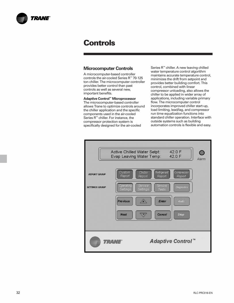
RLC-PRC016-EN32
Controls
Microcomputer Controls
A microcomputer-based controllercontrols the air-cooled Series R™ 70-125ton chiller. The microcomputer controllerprovides better control than pastcontrols as well as several new,important benefits.
Adaptive Control™ MicroprocessorThe microcomputer-based controllerallows Trane to optimize controls aroundthe chiller application and the specificcomponents used in the air-cooledSeries R™ chiller. For instance, thecompressor protection system isspecifically designed for the air-cooled
Series R™ chiller. A new leaving chilledwater temperature control algorithmmaintains accurate temperature control,minimizes the drift from setpoint andprovides better building comfort. Thiscontrol, combined with linearcompressor unloading, also allows thechiller to be applied in wider array ofapplications, including variable primaryflow. The microcomputer controlincorporates improved chiller start-up,load limiting, lead/lag, and compressorrun time equalization functions intostandard chiller operation. Interface withoutside systems such as buildingautomation controls is flexible and easy.

33RLC-PRC016-EN
Controls
Simple Interface With Other ControlSystemsMicrocomputer controls afford simpleinterface with other control systems,such as time clocks, building automationsystems and ice storage systems. Wiringto the unit can be as simple as twowires! This means you can have theflexibility to meet job requirements whilenot having to learn a complicated controlsystem.
Safety ControlsA centralized microcomputer offers ahigher level of machine protection. Sincethe safety controls are smarter, they limitcompressor loading to avoidcompressor or evaporator failures,thereby minimizing nuisance shutdown.The Unit Control Module (UCM) directlysenses the control variables that governthe loading of the chiller: motor currentdraw, evaporator temperature,condenser temperature, etc. When anyone of the variables approaches a limitcondition where the unit may bedamaged or shutdown on a safety, theUCM takes corrective action to avoidshutdown and keep the chiller operating.It does this through combined actions ofcompressor slide valve modulation,electronic expansion valve modulationand fan staging. The UCM optimizestotal chiller power consumption duringnormal operating conditions. Duringabnormal operating conditions, the UCMwill continue to optimize chillerperformance by taking the correctiveaction necessary to avoid shutdown.This keeps cooling capacity availableuntil the problem can be solved.
Whenever possible, the chiller is allowedto perform its function; make chilledwater. In addition, microcomputercontrols allow for more types ofprotection such as over and undervoltage. Overall, the safety controls helpkeep the building running and out oftrouble.
Monitoring And DiagnosticsSince the microcomputer provides allcontrol functions, it can easily indicatesuch parameters as leaving chilled watertemperature and capacity stage.If a failure does occur, one of over 90individual diagnostic and operatingcodes will be used to indicate theproblem, giving more specificinformation about the failure. All of themonitoring and diagnostic information isdisplayed directly on a microcomputerdisplay.
Interface With The Trane IntegratedComfort™ System (ICS)When the air-cooled Series R™ chiller isused in conjunction with a Trane Tracer™
system, the unit can be monitored andcontrolled from a remote location. Theair-cooled Series R™ chiller can becontrolled to fit into the overall buildingautomation strategy by using time ofday scheduling, timed override, dutycycling, demand limiting, and chillersequencing. A building owner cancompletely monitor the air-cooled SeriesR™ chiller from the Tracer system, as allof the monitoring information indicatedon the microcomputer can be read offthe Tracer system display. In addition, allthe powerful diagnostic information canbe read back at the Tracer system. Bestof all, this powerful capability comesover a single twisted pair of wires!
Air-cooled Series R™ chillers caninterface with many different externalcontrol systems, from simple stand-alone units to ice making systems. Eachunit requires a single-source, three-phase power supply and two 115-voltpower supplies. When an optionalcontrol power transformer is used, asingle 115-volt supply handles theevaporator heat tape. For basic stand-alone applications, the interface withoutside control is no different than forother Trane chillers. However, the RTAAunits have many features that can beused to interface with building controlsystems.
Standard Features
1. External Auto/StopA jobsite provided contact closure willturn the unit on and off.
Note: Do not use the chilled water pumpto stop the chiller.
2. Chilled Waterflow InterlockA jobsite provided contact closure froma chilled water pump contactor or a flowswitch is required and will allow unitoperation if a load exists. This featurewill allow the unit to run in conjunctionwith the pump system.
3. External InterlockA jobsite supplied contact opening wiredto this input will turn the unit off andrequire a manual reset of the unitmicrocomputer. This closure is typicallytriggered by a jobsite supplied systemsuch as a fire alarm.
4. Chilled Water Pump ControlUnit controls provide an output tocontrol chilled water pump(s). Onecontact closure to the chiller is all that isrequired to initiate the chilled watersystem.
5. Remote Running and Alarm IndicationContactsThe unit provides three single-pole/double-throw contact closures toindicate that a failure has occurred, if anycompressors are running, or if thecompressors are running at maximumcapacity. These contact closures may beused to trigger jobsite supplied alarmlights or alarm bells.

RLC-PRC016-EN34
Controls
Optional Features
1. Communication InterfaceCapability for communication with oneof the following control devices:
aTrane Tracer™ Building AutomationSystems
bRemote Display
2. External Chilled Water SetpointAllows the external setting independentof the front panel setpoint by one ofthree means:a) a remote resistor input (fixed oradjustable), b) a 2-10 VDC input, orc) a 4-20 mA input.
3. External Current Limit SetpointAllows the external setting independentof the front panel set point by one ofthree means:a) a remote resistor input (fixed oradjustable), b) a 2-10 VDC input, orc) a 4-20 mA input.
4. Ice Making ControlProvides interface with ice makingcontrol systems.
5. Chilled Water Temperature ResetReset can be based on return watertemperature or outdoor air temperature.The next section reviews therecommended interface with thefollowing control systems:
Stand-Alone UnitIntegrated Comfort™ System InterfaceNon-Trane Building Automation SystemsIce Making SystemsRemote Display
Each system description includes a list ofthose features which must be used,those features which can be used andwhich external Trane device is required.

35RLC-PRC016-EN
Trane Controls System
Tracer Summit controls — Interface WithThe Trane Integrated Comfort System(ICS)
Trane Chiller Plant ControlThe Tracer Summit Chiller Plant BuildingManagement System with Chiller PlantControl provides building automationand energy management functionsthrough stand-alone control. The ChillerPlant Control is capable of monitoringand controlling your entire chiller plantsystem.
Application software available:• Time-of-day scheduling• Demand limiting• Chiller sequencing• Process control language• Boolean processing• Zone control• Reports and logs• Custom messages• Run time and maintenance• Trend log• PID control loops
And of course, the Trane Chiller PlantControl can be used on a stand-alonebasis or tied into a complete buildingautomation system.
When the air-cooled Series R™ 70-125 tonchiller is used in conjunction with a TraneTracer™ Summit system, the unit can bemonitored and controlled from a remotelocation. The air-cooled Series R™ 70-125ton chiller can be controlled to fit into theoverall building automation strategy byusing time of day scheduling, timedoverride, demand limiting, and chillersequencing. A building owner cancompletely monitor the air-cooled SeriesR™ 70-125 ton chiller from the Tracersystem, since all of the monitoringinformation indicated on the unitcontroller’s microcomputer can be readoff the Tracer system display. In addition,all the powerful diagnostic informationcan be read back at the Tracer system.Best of all, this powerful capability comesover a single twisted pair of wires! Air-
Controls
Modem
Remote PC Workstation PC Workstation NotebookPC Workstation
LAN
BuildingControl Unit
BuildingControl Unit
VariTrane®
Variable Air VolumeTerminal
Room temperaturesensor Diffuser
VariTrane®
Variable Air VolumeTerminal
Room temperaturesensor Diffuser
Exhaust Fan
Air-cooled Series R™ Chiller
Modular Climate Changer®
Air Handler
cooled Series R™ 70-125 ton chillers caninterface with many different externalcontrol systems, from simple stand-alone units to ice making systems. Eachunit requires a single-source, three-phase power supply and a 115V/60Hz,220V/50Hz power supply. The addedpower supply powers the evaporatorheaters.
A single twisted pair of wires tied directlybetween the air-cooled Series R™ 70-125ton chiller and a Tracer™ Summit systemprovides control, monitoring anddiagnostic capabilities. Control functions
include auto/stop, adjustment of leavingwater temperature setpoint, compressoroperation lockout for kW demandlimiting and control of ice making mode.The Tracer system reads monitoringinformation such as entering and leavingevaporator water temperatures andoutdoor air temperature. Over 60individual diagnostic codes can be readby the Tracer system. In addition, theTracer system can provide sequencingcontrol for up to 25 units on the samechilled water loop. Pump sequencingcontrol can be provided from the Tracersystem. Tracer ICS is not available inconjunction with the remote display orthe external setpoint capability.

RLC-PRC016-EN36
Required Options
1Tracer Interface
Additional Options That May Be UsedIce Making Control
External Trane Devices RequiredTracer Summit™, Tracer 100 System orTracer Chiller Plant Control
Ice Making Systems ControlsAn ice making option may be orderedwith the air-cooled Series R™ chiller. Theunit will have two operating modes, icemaking and normal daytime cooling. Inthe ice making mode, the air-cooledSeries R™ 70-125 ton chiller will operateat full compressor capacity until thereturn chilled fluid temperature enteringthe evaporator meets the ice makingsetpoint. This ice making setpoint ismanually adjusted on the unit’s
Controls
microcomputer. Two input signals arerequired to the air-cooled Series R™ 70-125 ton chiller for the ice making option.The first is an auto/stop signal forscheduling and the second is required toswitch the unit in between the icemaking mode and normal daytimeoperation. The signals are provided by aremote job site building automationdevice such as a time clock or a manualswitch. In addition, the signals may beprovided over the twisted wire pair froma Tracer™ system.
Required OptionsExternal Auto/Stop (Standard)Ice Making Control
Additional Options That May Be UsedFailure Indication ContactsCommunications Interface (For TracerSystems)Chilled Water Temperature Reset
External Trane Devices Required —NoneNote: All wiring outside the unit issupplied at the job site.

37RLC-PRC016-EN
Controls
PC Workstation System LevelController
MP581 ProgrammableController
Air-cooled Series R™
Chiller
MP581 ProgrammableController
Ice Tanks
Boiler
Pumps
Simple Interface With Other ControlSystemsMicrocomputer controls afford simpleinterface with other control systems,such as time clocks, building automationsystems and ice storage systems. Thismeans you have the flexibility to meetjob requirements while not having tolearn a complicated control system. Thissetup has the same standard features asa stand-alone water chiller, with thepossibility of having the followingoptional features.
Alarm Indication ContactsThe unit provides three single-pole/double-throw contact closures toindicate that a failure has occurred,compressor on/off status, or if thecompressors are running at maximumcapacity. These contact closures may beused to trigger jobsite supplied alarmlights or alarm bells.
Other Control Systems
Interface With Other Control Systems
Stand-alone UnitInterface to stand-alone units is verysimple; only a remote auto/stop forscheduling is required for unit operation.Signals from the chilled water pumpcontactor auxiliary or a flow switch arewired to the chilled waterflow interlock.Signals from a timeclock or some otherremote device are wired to the externalauto/stop input.
Note: Do not use the chilled water pumpto stop the chiller.
Required Features
1. External Auto/Stop (Standard)
2. Chilled Waterflow Interlock (Standard)
Additional Features That May Be Used
1. Remote Running and Alarm IndicationContacts
2. External Interlock (Standard)
3. Chilled Water Temperature Reset
External Trane Devices Required —None
External Chilled Water SetpointAllows the external setting independentof the front panel setpoint by one of twomeans:a) 2-10 VDC input, orb) 4-20 mA input.
External Current Limit SetpointAllows the external setting independentof the front panel setpoint by one of twomeans:a) 2-10 VDC input, orb) 4-20 mA input.
Ice Making ControlProvides interface with ice makingcontrol systems.
Chilled Water Temperature ResetReset can be based on return watertemperature or outdoor air temperature.
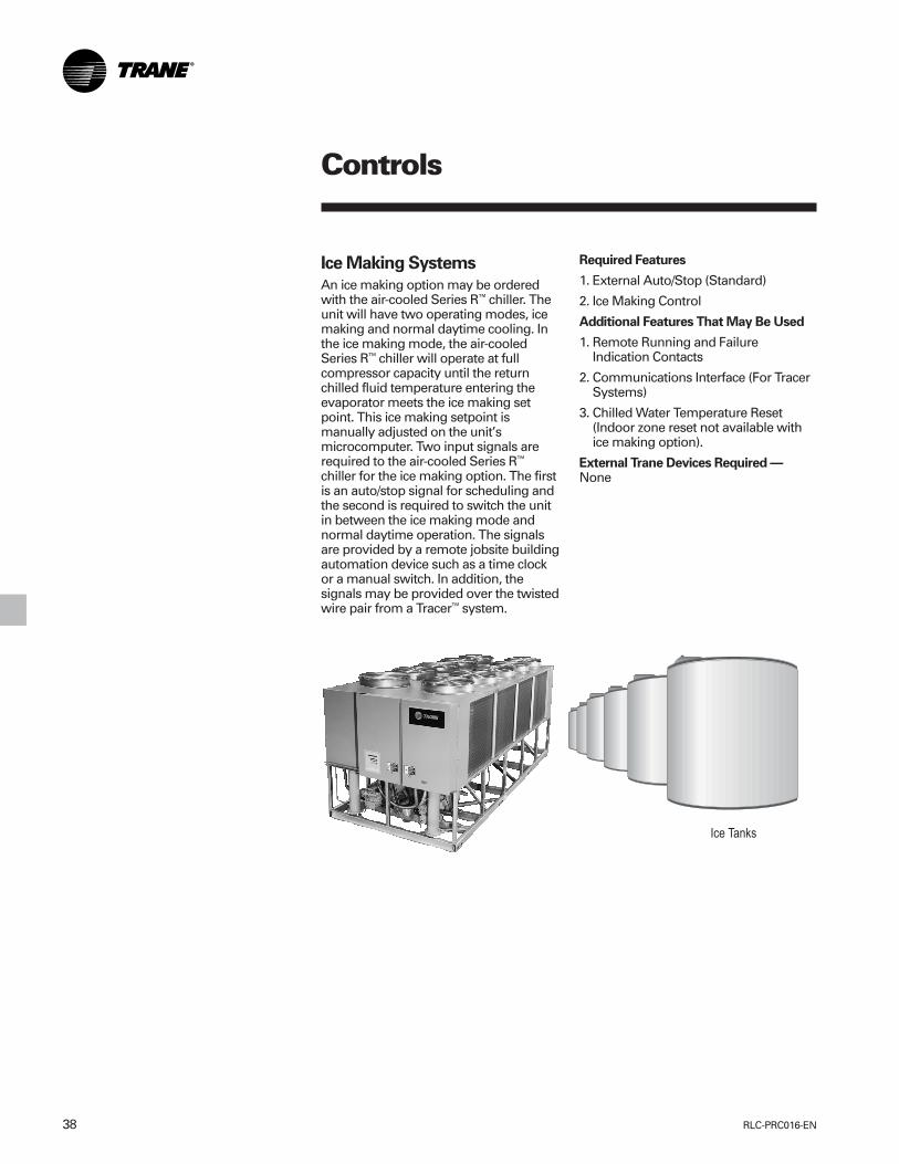
RLC-PRC016-EN38
Controls
Ice Making Systems
An ice making option may be orderedwith the air-cooled Series R™ chiller. Theunit will have two operating modes, icemaking and normal daytime cooling. Inthe ice making mode, the air-cooledSeries R™ chiller will operate at fullcompressor capacity until the returnchilled fluid temperature entering theevaporator meets the ice making setpoint. This ice making setpoint ismanually adjusted on the unit’smicrocomputer. Two input signals arerequired to the air-cooled Series R™
chiller for the ice making option. The firstis an auto/stop signal for scheduling andthe second is required to switch the unitin between the ice making mode andnormal daytime operation. The signalsare provided by a remote jobsite buildingautomation device such as a time clockor a manual switch. In addition, thesignals may be provided over the twistedwire pair from a Tracer™ system.
Required Features
1. External Auto/Stop (Standard)
2. Ice Making Control
Additional Features That May Be Used
1. Remote Running and FailureIndication Contacts
2. Communications Interface (For TracerSystems)
3. Chilled Water Temperature Reset(Indoor zone reset not available withice making option).
External Trane Devices Required —None

39RLC-PRC016-EN
Remote Display
The remote display option allows theoperator to monitor chiller operationfrom a remote location. Over 60 essentialchiller operating parameters can betransmitted between the unit controlmodule on the chiller and the remotedisplay via a bi-directionalcommunications link. Only one twistedwire pair is required between the chillerand the remote display. In addition tomonitoring chiller operation, alarms andunit diagnostics can be read from theremote display. Furthermore, the chilledwater temperature setpoint can beadjusted and the chiller can be turned onor off from the remote display.
Required Features
1. Communications Interface
Additional Features That May Be Used
1. External Interlock (Standard)
2. Chilled Water Temperature Reset
3. Chilled Waterflow Interlock(Standard)
4. Remote Running and FailureIndication Contacts
External Trane Devices Required
1. Remote Display Panel
Controls

RLC-PRC016-EN40
Dimensional Data
Figure D-1 — RTAA 70-125 Unit Dimensions
UNIT SIZE A B C D E F G K70-100 .492m 1.213m 2.851m 102mm 4.940m 2.317m 1.549m 1.626m
(1’-7 3/8”) (3’-11 3/4”) (9’-4 1/4”) (4”) (16’-2 1/2”) (7’-7 1/4”) (5’-1”) (5’-4”)110-125 .479m 1.032m 3.499m 152mm 5.626m 2.661m 1.511m 1.930m
(1’-6 7/8”) (3’-4 5/8”) (11’-5 3/4”) (6”) (18’-5 1/2”) (8’-8 3/4”) (4’-11 1/2”) (6’-4”)
NO. OF FANS PER UNITUNIT SIZE 70 80 90 100 110 125NO. FANSSTD UNIT 8 8 9 10 10 10
115 VOLT & LOW VOLTAGE CONNECTIONSPANEL TYPE L M N P QX-LINECONTROL .889m .927m 1.206m 1.245m 1.283mPANEL (2’-11”) (3’-0 1/2”) (3’-11 1/2”) (4’-1”) (4’-2 1/2”)WYE DELTACONTROL 76mm 114mm .39m .43m .47mPANEL (3”) (4 1/2”) (1’-3 1/2”) (1’-5”) (1’-8 1/2”)

41RLC-PRC016-EN
Weights
Table W-1 — Packaged Unit Weights (Aluminum)Isolator Location Operating Shipping
Unit Size Units 1 2 3 4 5 6 Weight WeightRTAA 70 lbs. 1582 1608 1212 1232 842 856 7332 7000
kg 718 729 550 559 382 388 3326 3175RTAA 80 lbs. 1587 1613 1218 1237 848 862 7365 7049
kg 720 732 552 561 385 391 3341 3197RTAA 90 lbs. 1639 1596 1271 1237 903 879 7525 7234
kg 743 724 577 561 410 399 3413 3281RTAA 100 lbs. 1640 1668 1281 1303 922 937 7751 7483
kg 744 757 581 591 418 425 3516 3394RTAA 110 lbs. 1933 1885 1480 1443 1027 1001 8769 8326
kg 877 855 671 655 466 454 3978 3777RTAA 125 lbs. 1871 1902 1445 1469 1019 1036 8742 8360
kg 849 863 655 666 462 470 3965 3792
Table W-2 — Packaged Unit Weights (Copper)Isolator Location Operating Shipping
Unit Size Units 1 2 3 4 5 6 Weight WeightRTAA 70 lbs. 1693 1719 1323 1343 953 966 7997 7665
kg 768 780 600 609 432 438 3627 3477RTAA 80 lbs. 1698 1724 1329 1348 959 972 8030 7714
kg 770 782 603 611 435 441 3642 3499RTAA 90 lbs. 1754 1711 1386 1352 1018 993 8214 7923
kg 796 776 629 613 462 450 3726 3594RTAA 100 lbs. 1759 1787 1400 1422 1041 1056 8465 8197
kg 798 811 635 645 472 479 3840 3718RTAA 110 lbs. 2065 2017 1612 1575 1159 1133 9561 9118
kg 937 915 731 714 526 514 4337 4136RTAA 125 lbs. 2016 2047 1590 1614 1164 1181 9612 9230
kg 914 928 721 732 528 536 4360 4187

RLC-PRC016-EN42
Options
Low Temperature BrineThe unit controls can be factory set tohandle low temperature brineapplications (0°F to 39°F).
Ice MakingThe unit controls can be factory set tohandle ice making for thermal storageapplications.
Building Automation SystemCommunication InterfacePermits either bi-directionalcommunication to the Trane IntegratedComfort™ system or permits remotechilled water setpoint and demandlimiting by accepting a 4-20 mA or 2-10Vdc analog signal.
Remote DisplayIn addition to controlling chilleroperation from remote location, theremote display shall provide thecapability to monitor unit alarms anddiagnostics. Only one twisted pair isrequired between the chiller and theremote display .
Remote EvaporatorThe remote evaporator is available as astandard option.
This option provides an easily installed,pre-engineered method of installing theevaporator remotely indoors.The remote evaporator is skid-mountedand is shipped separately from theoutdoor (condensing) unit. Refrigerantaccessories, including electronicexpansion valve, moisture indicatingsightglass and removable core filterdrier, are shipped with the evaporatorskid. All refrigerant connections arerouted to one end of the evaporator skidfor easy connection. All electrical wiringis factory installed and routed to aterminal box (entering and leaving watertemperature sensor, evaporatorrefrigerant temperature sensor andelectronic expansion valve controlwiring). Suction refrigerant temperaturesensors (two) must be field installed inthe field suction line piping next to theevaporator connections.
Chilled Water ResetThis option provides the control logicand field installed sensors for either loadbased (return water temperature) ortemperature based (ambient or zone)reset of leaving chilled watertemperature (requires CommunicationPackage).
Architectural Louvered PanelsLouvered panels cover the completecondensing coil and the service areabeneath the coils.
Coil ProtectionLouvered panels which protect thecondenser coils only.
Access ProtectionA coated wire mesh which covers accessarea underneath the condenser coils.
Control Power TransformerThis option eliminates the need to runseparate 115 volt control power to theunit. A control power transformer isfactory installed and wired. A separate115 volt power source is required for60 Hz heat tape.
Low Ambient OptionThe low ambient option consists of avariable speed drive on the first fan ofeach circuit and special control logic topermit low temperature operation.
Low Ambient LockoutA factory installed ambient sensor andcontrol logic can prevent starting belowthe recommended temperature.
Non-Fused Power Disconnect SwitchA non-fused disconnect switch with athrough the door handle is provided todisconnect main power.
Circuit BreakerA standard interrupting molded casecapacity circuit breaker (UL approved) isavailable. The circuit breaker can also beused to disconnect the chiller from mainpower with a through the door handleand comes pre-wired from the factorywith terminal block power connections.
Neoprene IsolatorsIsolators provide isolation betweenchiller and structure to help eliminatefrequency transmission. Neopreneisolators are more effective andrecommended over spring isolators.
Spring IsolatorsSpring isolators help isolate the chillerfrom the building structure.
Condenser Corrosion ProtectionCopper fins and CompleteCoat areavailable on all size units for corrosionprotection. Job site conditions should bematched with the appropriate condenserfin materials to inhibit coil corrosion andensure extended equipment life. TheCompleteCoat option provides fullyassembled coils with a flexible dip andbake epoxy coating.
Convenience OutletProvides a 15 amp, 115 volt (60 Hz)convenience outlet on the unit.

43RLC-PRC016-EN
Typical WiringDiagram 70-125 Tons
NOTES:
1. DASHED LINES INDICATE RECOMMENDED FIELD WIRING BY OTHERS.PHANTOM LINES INDICATE ALTERNATE CIRCUITRY OR AVAILABLE SALESOPTION. CHECK SALES ORDER TO DETERMINE IF WIRING IS REQUIREDFOR SPECIFIC OPTIONS.
2. ALL THREE PHASE MOTORS SUPPLIED WITH THE UNIT ARE PROTECTEDUNDER PRIMARY SINGLE PHASE FAILURE CONDITIONS.
3. CAUTION - DO NOT ENERGIZE UNIT UNTIL CHECK OUT AND START-UPPROCEDURES HAVE BEEN COMPLETED.
4 SEE INSERT “A” FOR RESISTOR CONNECTIONS TO PROGRAM ANEXTERNAL CHILLED WATER SETPOINT WHEN 4 - 20 mA OR A 2 - 10 VDCSIGNAL IS NOT USED. SEE THE OPERATORS MANUAL FOR RESISTORVALUES.
5 SEE INSERT “B” FOR RESISTOR CONNECTIONS TO PROGRAM ANEXTERNAL CURRENT LIMIT SETPOINT WHEN 4 - 20 mA OR A 2 - 10 VDCSIGNAL IS NOT USED. SEE THE OPERATORS MANUAL FOR RESISTORVALUES.
6 SEE INSERT “C” FOR CONTACTS (IN PLACE OF THE ZONE TEMP. SENSOR)FOR OPTIONAL ICE MACHINE CONTROL - OPTION “A”.
7. THE FOLLOWING CAPABILITIES ARE OPTIONAL - THEY AREIMPLEMENTED AND WIRED AS REQUIRED FOR A SPECIFIC SYSTEMAPPLICATION.
A ICE-MACHINE CONTROL (CANNOT BE USED WITH OPT. L)
B COMMUNICATIONS INTERFACE
D WYE-DELTA CLOSED TRANSITION STARTER
E CONTROL POWER TRANSFORMER.
H UNIT DISCONNECT, NON-FUSED
J CHILLED WATER RESET - RETURN WATER
K CHILLED WATER RESET - OUTDOOR AIR
L CHILLED WATER RESET - ZONE AIR (CANNOT BE USED WITH OPT. A)
O LOW AMBIENT LOCKOUT
S CHILLED WATER FLOW SWITCH (NOT REQUIRED FOR CHILLERPROTECTION)
T REMOTE CLEAR LANGUAGE DISPLAY
WIRING AND CONTACT REQUIREMENTS:
20. ALL FIELD WIRING MUST BE IN ACCORDANCE WITH THE NATIONALELECTRICAL CODE (NEC), STATE, AND LOCAL REQUIREMENTS. OUTSIDETHE UNITED STATES, OTHER COUNTRIES APPLICABLE NATIONAL AND/OR LOCAL REQUIREMENTS SHALL APPLY.
21 FOR UNITS WITHOUT THE CONTROL POWER TRANSFORMER (1T1)OPTION, THE CUSTOMER MUST PROVIDE CONTROL POWER OF 115 VAC,60 HERTZ, SINGLE PHASE, 750 VA ON 130 THRU 215 TON UNITS. THECONTROL POWER TRANSFORMER (1T1) IS STANDARD ON 50 HERTZUNITS.
22 FOR ALL UNITS, THE HEAT TAPE MUST BE POWERED FROM A SEPARATECUSTOMER PROVIDED 115 VAC, 420 WATT SOURCE FOR 200/230/420/57560 HZ UNITS: 220 VAC, 420 WATT SOURCE FOR 346/1380/415 50 HZ UNITS.FOR THE OPTIONAL HEAT RECOVERY HEAT TAPE IS 420 WATTS.
23 CUSTOMER SUPPLIED CONTACTS MUST BE COMPATIBLE WITH DRYCIRCUIT 12 VDC, 45 mA RESISTIVE LOAD. SILVER OR GOLD PLATEDCONTACTS ARE RECOMMENDED.
24 30 VOLT OR LESS CIRCUIT. DO NOT RUN IN CONDUIT WITH HIGHERVOLTAGE CIRCUITS. USE #14-18 AWG. SEE SELECTION TABLE.
25 MINIMUM PILOT DUTY CONTACT RATING AT 115 VAC; 5.9 VA INRUSH, 1.3VA SEALED.
26 FIELD WIRED ELECTRICAL LOADING IS NOT TO EXCEED THE FOLLOWINGRATINGS:
TERMINALS DEVICE VOLTAGE SEALED VA INRUSH VA
1U1-TB4-1,2 1U1K1,NO 115 180 1150*1U1-TB4-3 1U1K1,NC 115 180 1150*1U1-TB4-5,4 1U1K2,NO 115 180 1150*1U1-TB4-6,7 1U1K3,NC 115 180 1150*1U1-TB4-8,9 1U1K2,NO 115 250 1150*1U1-TB4-10,11 1U1K3,NC 115 180 1150*
*STANDARD PILOT DUTY RATING (35% POWER FACTOR).
27 WHEN CUSTOMER INPUT IS REQUIRED, REMOVE JUMPER AND INSTALLCUSTOMER WIRING.
28 CHILLED WATER PUMP CONTROL FROM TRANE UNIT UCM MODULECHILLED WATER PUMP IS REQUIRED TO OPERATE A MINIMUM OF 1MINUTE AFTER A COMMAND TO TERMINATE CHILLER OPERATION (UCMWILL PROVIDE THE DELAY CONTACTS). CHILLED WATER SYSTEMDEMAND SWITCH (5S2) IS CONNECTED TO THE UCM EXTERNAL AUTO/STOP INPUT. NOTE: DO NOT USE THE CHILLED WATER PUMP TO STOPTHE CHILLER.
29 AS SHIPPED 380/415 50 HZ VOLT UNIT TRANSFORMER 1T1-(OPTIONAL) ISWIRED FOR 415 VOLT OPERATION. IF UNIT IS TO BE OPERATED ON A 380VOLT POWER SUPPLY, RE-CONNECT AS SHOWN IN INSET “D”.REPROGRAM “UNIT LINE VOLTAGE” IN SERVICE SETTING MENU OFCLEAR LANGUAGE DISPLAY FROM 415 TO 380.
30 K1, K2, K3 RELAY OUTPUTS CAN BE PROGRAMMED TO PERFORMALTERNATE FUNCTIONS. SEE INSTALLATION, OPERATION ANDMAINTENANCE MANUAL FOR DETAILS. FUNCTION #1 IS SHOWN.

RLC-PRC016-EN44
Typical WiringDiagram 70-125 Tons

45RLC-PRC016-EN
FeaturesSummary
Reliability• Proven Trane helical rotary screw
compressor design for longer life andgreater dependability.
• Fewer moving parts means less parts tofail. Typical reciprocating compressorshave 4 times as many total parts and 15times as many critical parts.
• Adaptive Control™ protects the chillerwhen any of the system variablesapproaches a limit condition that maydamage the unit or cause a shutdown.The Unit Control Module takescorrective action to keep the unitrunning.
• Dual circuit design increases overallsystem reliability.
• Unlike reciprocating designs, thiscompressor can handle liquid slugging.
• Suction gas cooling allows the motor tooperate at lower temperatures forlonger life.
Trane RTAA Air-CooledSeries R™ ChillerDesigned To Perform, Built To Last
Performance• Superior full load efficiency. All units
meet ASHRAE 90.1-2001 Standard.• Excellent part load performance is
achieved without resorting tomanifolded multiple reciprocatingcompressors.
• Use of an electronic expansion valvesignificantly improves part loadperformance by minimizing superheatin the evaporator and allowing thechiller to run at reduced condensingtemperatures.
• Unique compressor sequencingequalizes not only starts, but operatinghours as well.
Trouble-Free Operation and Start-Up• Adaptive Control™ microprocessor
keeps the Series R™ chiller on-linewhen others would shut down.
• Fewer nuisance trips means lessexpense from unnecessary servicecalls.
• Factory installed and tested optionskeep start-up time and expensesminimized.
• Easy interface capability with the TraneIntegrated Comfort™ system via asingle twisted pair of wires.
• Optional remote display panelsimplifies chiller monitoring/ control.
• Packed stock availability for yourordering convenience.

RLC-PRC016-EN46
MechanicalSpecifications
GeneralUnits are leak and pressure tested at 450psig high side, 300 psig low side, thenevacuated and charged. Packaged unitsship with a full operating charge of oiland refrigerant. Unit panels, structuralelements and control boxes areconstructed of 12-gauge galvanized steeland mounted on a welded structuralsteel base. Unit panels and control boxesare finished with a baked on powderpaint, and the structural base with an airdry paint. All paint meets therequirement for outdoor equipment ofthe U.S. Navy and other federalgovernment agencies.
EvaporatorThe evaporator is a tube-in-shell heatexchanger design with internally finnedcopper tubes roller expanded into thetube sheet. The evaporator is designed,tested and stamped in accordance withASME for a refrigerant side workingpressure of 300 psig. The evaporator isdesigned for a water side workingpressure of 215 psig. Water connectionsare grooved pipe. The evaporator hasone water pass with a series of internalbaffles. Each shell includes a vent, adrain and fittings for temperature controlsensors and is insulated with 3/4-inchArmaflex II or equal insulation (K=0.26).Heat tape with thermostat is provided toprotect the evaporator from freezing atambient temperatures down to -20°F.
Condenser and FansAir-cooled condenser coils havealuminum fins mechanically bonded tointernally finned seamless coppertubing. The condenser coil has anintegral subcooling circuit and alsoprovides oil cooling for the compressorbearing and injection oil. Condensers arefactory proof and leak tested at506 psig.
Direct-drive vertical discharge condenserfans are dynamically balanced. Three-phase condenser fan motors withpermanently lubricated ball bearing andinternal thermal overload protection areprovided. Standard units will start andoperate down to 25°F ambient.
Compressor and Lube Oil SystemThe rotary screw compressor is semi-hermetic, direct drive, 3600 rpm, withcapacity control slide valve, rollingelement bearings, differential refrigerantpressure oil pump and oil heater. Themotor is a suction gas cooled,hermetically sealed, two-pole squirrelcage induction motor.
Oil separator and filtration devices areprovided separate from the compressor.Check valves in the compressordischarge and lube oil system and asolenoid valve in the lube system areprovided.
Remote EvaporatorThe evaporator is a tube-in-shell heatexchanger, designed with internally-finned copper tubes that are rolledexpanded into the tube sheet. Theevaporator is designed, tested andstamped for a refrigerant side workingpressure of 300 psig, in accordance withASME. The evaporator is designed for awater side working pressure of 215 psig.Water connections are victaulic. Theevaporator has one water pass, with aseries of internal baffles.
Each shell includes a vent and drainconnection, as well as factory-mountedentering and leaving water temperaturecontrol sensors and evaporatorrefrigerant temperature sensors. Theevaporator is insulated with 3/4-inchArmaflex II or equal insulation (K=0.26).
The evaporator is skid-mounted and isshipped separately from the outdoor(condensing) unit. Refrigerantaccessories, including electronicexpansion valve, moisture indicatingsightglass and removable core filterdrier, are shipped with the evaporatorskid. All refrigerant connections arerouted to one end of evaporator skid foreasy connection. All electrical wiring isfactory installed and routed to a terminalbox (entering and leaving watertemperature sensor, evaporatorrefrigerant temperature sensor andelectronic expansion valve controlwiring). Suction refrigerant temperaturesensors (two) must be field installed inthe field suction line piping next to theevaporator connections.

47RLC-PRC016-EN
MechanicalSpecifications
Refrigeration CircuitsEach unit has two refrigerant circuits,with one rotary screw compressor percircuit. Each refrigerant circuit includes acompressor suction and dischargeservice valve, liquid line shutoff valve,removable core filter drier, liquid linesight glass with moisture indicator,charging port and an electronicexpansion valve. Fully modulatingcompressors and electronic expansionvalves provide variable capacitymodulation over the entire operatingrange.
Unit ControlsAll unit controls are housed in aweathertight enclosure with removableplates to allow for customer connectionof power wiring and remote interlocks.All controls, including sensors, arefactory mounted and tested prior toshipment. All cataloged units areUL listed.
Microcomputer controls provide allcontrol functions including start-up andshut down, leaving chilled watertemperature control, compressor andelectronic expansion valve modulation,fan sequencing, antirecycle logic,automatic lead/lag compressor startingand load limiting.
The unit control module, utilizingAdaptive Control™ microprocessor,automatically takes action to avoid unitshutdown due to abnormal operatingconditions associated with lowrefrigerant temperature, high condensingtemperature and motor current overload.Should the abnormal operating conditioncontinue until a protective limit isviolated, the unit will be shut down.
Unit protective functions include loss ofchilled water flow, evaporator freezing,loss of refrigerant, low refrigerantpressure, high refrigerant pressure,reverse rotation, compressor startingand running over current, phase loss,phase imbalance, phase reversal, andloss of oil flow.
A menu driven digital display indicatesover 20 operating data points includingchilled water setpoint, current limitsetpoint, leaving chilled watertemperature, evaporator and condenserrefrigerant pressures and temperatures.Over 60 diagnostic checks are made anddisplayed when a problem is detected.The digital display can be read andadvanced on the unit without openingany control panel doors.
Standard power connections includemain three phase power and two 115volt single phase power connections forcontrol power and heat tape.
StartersStarters are housed in a weathertightenclosure with removable cover plate toallow for customer connection of powerwiring. Across-the-line starters arestandard on all 460-575 volt units. Anoptional Wye Delta closed transitionstarter (33 percent of LRA inrush) isavailable. Typically, Trane helical rotarycompressors are up to full speed in onesecond when started across-the-line andhave equivalent inrush with similar sizereciprocating compressor with part windstarters.
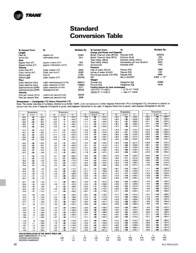
RLC-PRC016-EN48
StandardConversion Table


Trane has a policy of continuous product and product data improvement and reserves the right to changedesign and specifications without notice.
Literature Order Number
File Number
Supersedes
Stocking LocationTrane
A business of American Standard Companies
www.trane.com
For more information contact your local districtoffice or e-mail us at [email protected]
RLC-PRC016-EN
PL-RF-RLC-PRC016-EN-08 02
RLC-DS-2
Inland-La Crosse