an xps study of oxyf luorinated multiwalle d carbon nano...
TRANSCRIPT
Vol. 8, No. 4 December 2007 pp. 292-298
An XPS Study of Oxyfluorinated Multiwalled Carbon Nano Tubes
Seok-Min Yun1, Ju-Wan Kim2, Min-Jung Jung1, Young Chang Nho3,
Phil Hyun Kang3 and Young-Seak Lee1,2,♠
1Dept. of Fine Chemical Engineering and Chemistry, Chungnam National University, 305-764, South Korea2Dept. of Nanotechnology, Chungnam National University, 305-764, South Korea
3Radiation Application Research Division, Korea Atomic Energy Research Institute, Daejeon 305-600, Korea♠e-mail:[email protected]
(Received August 17, 2007; Accepted November 19, 2007)
Abstract
In order to investigate functional groups on the surface of Multi-walled Carbon Nanotubes (MWCNTs) induced byoxyfluorination, XPS (X-ray photoelectron spectroscopy) analysis was carried out. All core level spectra of MWCNTs weredeconvoluted to several Pseudo-Voigt functions (sum of Gaussian-Lorentzian functions). Both O1s and F1s binding energy ofoxyfluorinated MWCNTs shifted high value as increment of fluorine mixing ratio. The carbon-fluorine covalent bondingconcentration increased as increment of fluorine mixing ratio. The shape and intensity of OF10-MWCNTs are similar withthose of as-received MWCNTs. However, the intensity and binding energies of main peak position of OF20-MWCNTs andOF30-MWCNTs were dramatically increased by oxyfluorination.
Keywords : MWCNTs, Oxyfluorination, XPS, Pseudo-Voigt functions
1. Introduction
Since the discovery of synthetic methods of carbon
nanotubes (CNTs) by Iijima in 1991[1], many research
groups have been studying about these structure [2-5],
properties [6-8] and application [9, 10]. In specialty, in order
to improve dispersibility and reactivity, an attempt to induce
functional groups on the surface of CNTs was gone on [11].
Among these methods, fluorination is one of the effective
methods [12, 13]. The strongest electronegativity of F- ion
leads to strong bonding between fluorine and other elements
[14]. The chemical composition, as well as the structure of
carbon materials obtained by fluorination is dependent on
the structure and characteristics of starting materials and on
the fluorination conditions. In addition, using fluorine-
oxygen mixed gas can induce the functionalization with
oxygen groups even on the surface of CNTs which have high
chemical stability [14]. Many studies have been carried out
on fluorinated carbon materials and defined the interaction
between carbon surface and fluorine atom, which have found
important practical applications [12-15]. There are several
kinds of interaction between carbon and fluorine (carbon-
fluorine covalent, semi-ionic, ionic and van der Waals
interaction) [15].
Although some studies about the carbon/fluorine system
and the properties of CNTs were carried out by other research
groups, the oxyfluorination (fluorination using oxygen-
fluorine mixed gas) on CNTs is still fresh ground. Especially,
there are few papers reported about the oxygen groups
bonded at carbon atoms onto CNT by oxyfluorination.
In the present study, we report and discuss the results
obtained by X-ray photoelectron spectroscopy (XPS) analy-
sis of the oxyfluorinated multi-walled carbon nanotubes
(MWCNTs) with different fluorine-oxygen mixing ratio.
2. Experimental
2.1. Materials
MWCNTs were obtained from NK CNT Co., Korea. It
was grown by the vapor growth method using acetylene
(C2H2) as carbon source and ironpentacarbonyl (Fe(CO)5) as
catalyst and purified by chemical and thermal treatment [16].
The nanotubes used in this study are under 20 µm long, and
outer and inner diameters are 60-80 nm and 30-50 nm,
respectively. Fluorine gas used for oxyfluorination, were
supplied by Messer Grieheim GmbH (99.8%). Oxygen
(99.999%) and argon (99.999%) gas were used also.
2.2. Oxyfluorination
Fig. 1 shows the schematic diagram of oxyfluorination
apparatus. Oxyfluorination apparatus consists of a reactor,
vacuum-pump and buffer-tank connected gas cylinders. Prior
to oxyfluorination, fluorine and oxygen gas were mixed with
Carbon
Letters

An XPS Study of Oxyfluorinated Multiwalled Carbon Nano Tubes 293
fluorine partial pressure, in the ratio of 0.1, 0.2 and 0.3 in
buffer-tank for 24 h. 1 g of MWCNTs was loaded on nickel
boat in the reactor and was degassed at 473 K for 2 h.
Oxyfluorination was carried out at 373 K for 1 h after
introduction of prepared mixed gas to 1 bar. Non-treated
MWCNTs and oxyfluorinated MWCNTs with different
mixing ratio of fluorine and oxygen gas were named as
follows; as-received MWCNTs, OF10-MWCNTs, OF20-
MWCNTs and OF30-MWCNTs, respectively.
2.3. XPS analysis
The XPS spectra of the MWCNTs used in this study were
obtained with MultiLab 2000 spectrometer (Thermo electron
corporation, England) to the changes of chemical species on
the surface of MWCNTs before and after oxyfluorination. Al
Ká(1485.6 eV) was used as X-ray source at 14.9 keV of
anode voltage, 4.6 A and 20 mA as filament current and
emission current, respectively. All samples were treated at
10−9 mbar to remove impurities. The survey spectra were
obtained at 50 eV of pass energy and 0.5 eV of step size.
Core level spectra were also obtained at 20 eV and 0.05 eV
as pass energy and step size, respectively [16].
3. Results and discussion
The survey spectra in the 0-1300 eV of binding energy
range were investigated to identify the elements on the
surface of samples and perform a quantitative analysis. The
survey spectra of MWCNTs oxyfluorinated with different
mixing ratio of fluorine-oxygen gas and as-received
MWCNTs are shown Fig. 2. All of the survey spectra show
distinct carbon and oxygen peaks at around 285.0 eV and
533.0 eV, respectively. And fluorine peaks were found at
around 687.7 eV on oxyfluorinated MWCNTs. The atomic
ratio and binding energy of each element on the surface of
MWCNTs were listed in Table 1. The binding energies of all
peaks were corrected as compare with reference peak
(graphite C1s, 285.0 eV). The surface carbon concentration
of samples dramatically decreased after oxyfluorination with
OF20-MWCNTs and OF30-MWCNTs, whereas fluorine
atomic ratio of OF20-MWCNTs and OF30-MWCNTs si-
Fig. 1. Schematic diagram of a fluorination apparatus.
Fig. 2. XPS wide scan spectra of as-received MWCNTs (a);OF10-MWCNTs (b); OF20-MWCNTs (c); OF30-MWCNTs (d).
Table 1. XPS surface element analysis parameters of as-received and oxyfluorinated MWCNTs
Samples
C1s O1s F1s
O1s/C1s(atomic ratio/%)
F1s/C1s(atomic ratio/%)
Atomicpercent(at%)
Bindingenergy(eV)
Atomicpercent(at%)
Bindingenergy(eV)
Atomicpercent(at%)
Bindingenergy(eV)
As-received MWCNTs 95.01 285.0 4.99 532.64 - - 5.25 -
OF10-MWCNTs 91.37 285.0 5.00 532.93 3.63 687.50 5.47 3.97
OF20-MWCNTs 76.86 285.0 6.09 533.42 17.05 687.52 7.92 22.18
OF30-MWCNTs 67.08 285.0 7.34 533.46 25.58 687.60 10.94 38.13

294 Seok-Min Yun et al. / Carbon Letters Vol. 8, No. 4 (2007) 292-298
gnificantly increased. And O1s peaks of oxyfluorinated
MWCNTs slightly increased according to increment of
fluorine partial pressure. And both O1s and F1s binding
energy of oxyfluorinated MWCNTs shifted high value. From
the results of table 1, it is clear that oxyfluorination with
higher fluorine ratio is more effective to induce functional
groups on carbon surface.
Fig. 3 showed core level C1s spectra of as-received and
oxyfluorinated MWCNTs with different fluorine-oxygen
mixing ratio. The C1s peaks were obtained in the range of
binding energy from 281 to 296 eV. The C1s peaks of
oxyfluorinated MWCNTs were deconvoluted to several
Pseudo-Voigt functions (sum of Gaussian-Lorentzian func-
tion) by peak analysis program obtained from Unipress Co.,
USA [17]. The Pseudo-Voigt function is given by
(1)
Where, F (E) is intensity at energy E, H is peak height, E0 is
peak centre, FWHM is full with at half maximum and S is
shape function related with symmetry and Gaussian-Lo-
rentzian mixing ratio. The assignments for the different
components of C1s were listed in Table 2 [12, 15, 18, 19].
The C1s spectra of oxyfluorinated MWCNTs have been fitt-
ed into 10 components in order to evaluate the components
induced by oxyfluorination. The main peak of all samples is
C(1) corresponding to non-functionalizes sp2 and sp3 carbon
atoms. In this case, because MWCNTs have rolled graphite
structure, we assumed that the C(1) component is sp2 carbon
atoms. The C(1) component concentrations of samples are
88.1% (as-received MWCNTs), 68.1% (OF10-MWCNTs),
51.8% (OF20-MWCNTs) and 33.8% (OF30-MWCNTs),
respectively. It suggests that high concentration of fluorine
lead to destruction of sp2 structure. Touhara et al[20]
reported that sp2 carbon atoms reformed to sp3 carbon atoms
after fluorination. We confirmed similar result in XPS
results. C(2) component assigned to aliphatic sp3 carbon
atoms, are 7.3% (as-received MWCNTs), 14.1% (OF10-
MWCNTs), 17.0% (OF20-MWCNTs) and 20.5% (OF30-
MWCNTs), respectively. According to component con-
centration of C(1) and C(2), C(1) concentrations decreased,
whereas C(2) concentration increased as increment of
fluorine concentration. As shown in Table 2, higher numbers
of carbon components from C(6) to C(10) correspond to
carbon-fluorine covalent bonding. Nansé et al. suggested two
F E( ) H 1 S–( ) In 2( )E E0–
FWHM-------------------⎝ ⎠
⎛ ⎞2
–⎝ ⎠⎛ ⎞exp
---
---+=
S
1E E0–
FWHM-------------------⎝ ⎠
⎛ ⎞2
+
------------------------------------+
Fig. 3. Deconvolution of the core level C1s spectra: as-received MWCNTs (a); OF10-MWCNTs (b); OF20-MWCNTs (c); OF30-MWCNTs (d).
An XPS Study of Oxyfluorinated Multiwalled Carbon Nano Tubes 295
types of carbon-fluorine bonding structure (Type I and Type
II of fluorinated carbon structure). The surface fluorinated
carbons in which carbon-carbon skeleton and the carbon-
carbon length do not significantly changed from those of as-
received carbon structure are Type I structure. Whereas,
Type II structure is fluorinated carbons where sp2 carbon
sheets of planar conformation are reformed to sp3 puckered
structure. In the results from Table 3 and Fig. 3, the
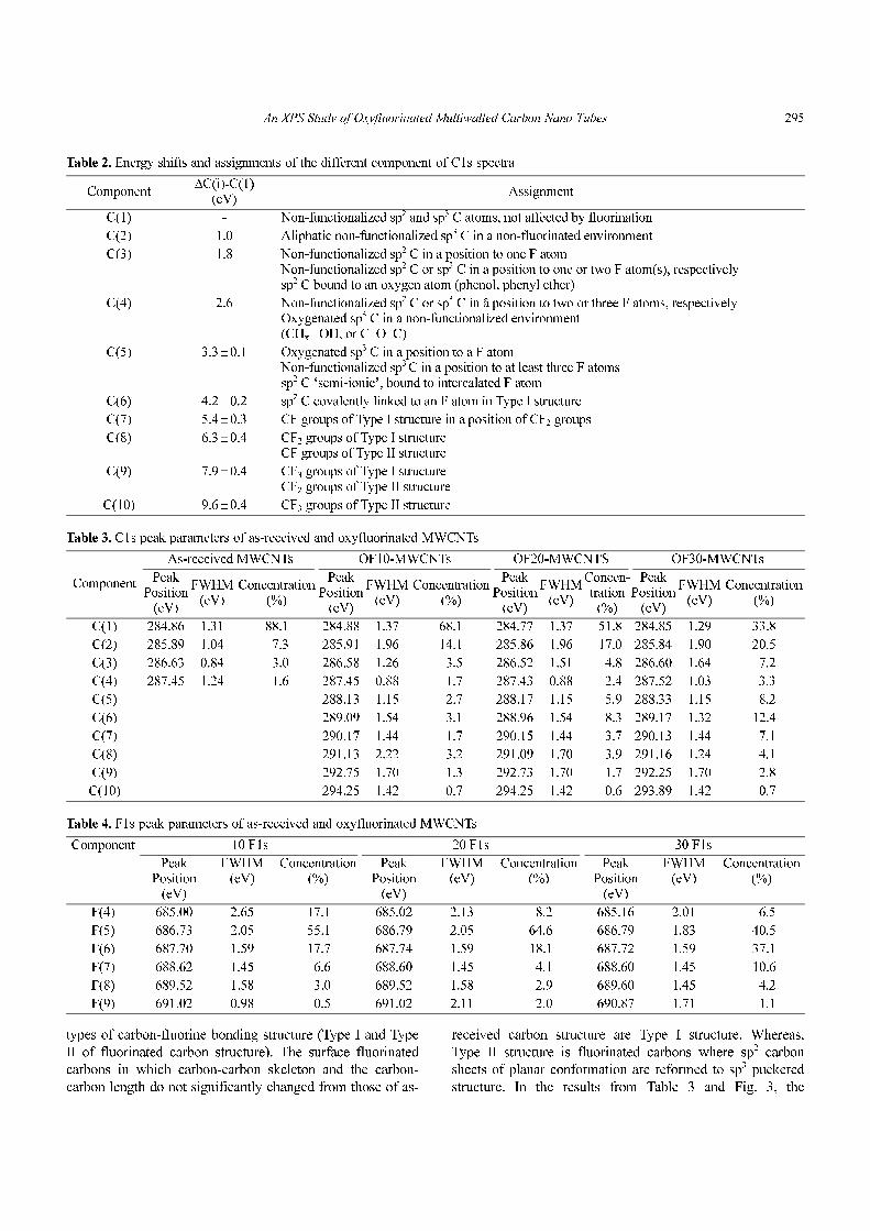
Table 2. Energy shifts and assignments of the different component of C1s spectra
Component∆C(i)-C(1)
(eV)Assignment
C(1) - Non-functionalized sp2 and sp3 C atoms, not affected by fluorination
C(2) 1.0 Aliphatic non-functionalized sp3 C in a non-fluorinated environment
C(3) 1.8 Non-functionalized sp2 C in a position to one F atom Non-functionalized sp2 C or sp3 C in a position to one or two F atom(s), respectivelysp2 C bound to an oxygen atom (phenol, phenyl ether)
C(4) 2.6 Non-functionalized sp2 C or sp3 C in â position to two or three F atoms, respectivelyOxygenated sp3 C in a non-functionalized environment(CHx –OH, or C–O–C)
C(5) 3.3±0.1 Oxygenated sp3 C in a position to a F atomNon-functionalized sp3 C in a position to at least three F atomssp2 C ‘semi-ionic’, bound to intercalated F atom
C(6) 4.2±0.2 sp2 C covalently linked to an F atom in Type I structure
C(7) 5.4±0.3 CF groups of Type I structure in a position of CF2 groups
C(8) 6.3±0.4 CF2 groups of Type I structureCF groups of Type II structure
C(9) 7.9±0.4 CF3 groups of Type I structureCF2 groups of Type II structure
C(10) 9.6±0.4 CF3 groups of Type II structure
Table 3. C1s peak parameters of as-received and oxyfluorinated MWCNTs
Component
As-received MWCNTs OF10-MWCNTs OF20-MWCNTS OF30-MWCNTs
PeakPosition
(eV)
FWHM(eV)
Concentration(%)
PeakPosition
(eV)
FWHM(eV)
Concentration(%)
PeakPosition
(eV)
FWHM(eV)
Concen-tration
(%)
PeakPosition
(eV)
FWHM(eV)
Concentration(%)
C(1) 284.86 1.31 88.1 284.88 1.37 68.1 284.77 1.37 51.8 284.85 1.29 33.8
C(2) 285.89 1.04 7.3 285.91 1.96 14.1 285.86 1.96 17.0 285.84 1.90 20.5
C(3) 286.63 0.84 3.0 286.58 1.26 3.5 286.52 1.51 4.8 286.60 1.64 7.2
C(4) 287.45 1.24 1.6 287.45 0.88 1.7 287.43 0.88 2.4 287.52 1.03 3.3
C(5) 288.13 1.15 2.7 288.17 1.15 5.9 288.33 1.15 8.2
C(6) 289.09 1.54 3.1 288.96 1.54 8.3 289.17 1.32 12.4
C(7) 290.17 1.44 1.7 290.15 1.44 3.7 290.13 1.44 7.1
C(8) 291.13 2.22 3.2 291.09 1.70 3.9 291.16 1.24 4.1
C(9) 292.75 1.70 1.3 292.73 1.70 1.7 292.25 1.70 2.8
C(10) 294.25 1.42 0.7 294.25 1.42 0.6 293.89 1.42 0.7
Table 4. F1s peak parameters of as-received and oxyfluorinated MWCNTs
Component 10 F1s 20 F1s 30 F1s
PeakPosition
(eV)
FWHM(eV)
Concentration(%)
PeakPosition
(eV)
FWHM(eV)
Concentration(%)
PeakPosition
(eV)
FWHM(eV)
Concentration(%)
F(4) 685.00 2.65 17.1 685.02 2.13 8.2 685.16 2.01 6.5
F(5) 686.73 2.05 55.1 686.79 2.05 64.6 686.79 1.83 40.5
F(6) 687.70 1.59 17.7 687.74 1.59 18.1 687.72 1.59 37.1
F(7) 688.62 1.45 6.6 688.60 1.45 4.1 688.60 1.45 10.6
F(8) 689.52 1.58 3.0 689.52 1.58 2.9 689.60 1.45 4.2
F(9) 691.02 0.98 0.5 691.02 2.11 2.0 690.87 1.71 1.1

296 Seok-Min Yun et al. / Carbon Letters Vol. 8, No. 4 (2007) 292-298
Fig. 4. Deconvolution of the core level F1s spectra: OF10-MWCNTs (a); OF20-MWCNTs (b); OF30-MWCNTs (c).
Fig. 5. Deconvolution of the core level O1s spectra: as-received MWCNTs (a); OF10-MWCNTs (b); OF20-MWCNTs (c); OF30-MWCNTs (d).

An XPS Study of Oxyfluorinated Multiwalled Carbon Nano Tubes 297
component ratios of carbon-fluorine covalent bonding are
10% (OF10-MWCNTs), 18.2% (OF20-MWCNTs) and
27.1% (OF30-MWCNTs), respectively. The carbon-fluorine
covalent bonding concentration increased as increment of
fluorine mixing ratio. The four components between C(1)
and C(6) are attributed to carbon atoms which is located at
β-position of fluorine atoms. The difference between binding
energy of C(1) and binding energies of other components is
fluorination degree. The detail results of each carbon
component are listed in Table 3.
The F1s core level spectra of oxyfluorinated MWCNTs
show in Fig. 4. The F1s main component of all samples is
F(5) located around 686.73. This peak is attributes to semi-
ionic bound fluorine which is intercalated sp2 carbons [21].
Component F(4) is corresponding to adsorbed or entrapped
fluorine. As Table 4, F(4) concentrations decreased as
increment fluorine mixing ratio. Covalently bonded fluorine
atoms are attributed to F(6) to F(10). Among these
components, F(6) and F(7) are Type I structure. Especially,
F(6) located around 687.7 eV, is corresponding to C(6). The
difference between F(6) and F(7) is about 0.9 eV. This
phenomenon is results from charging effect of fluorine
atoms. Perfluorinated carbon-fluorine bonding, Type II
structures are located around 689.5 eV and 691.0 eV
corresponding to F(8) and F(9), respectively. The assign-
ments of each component are listed in Table 5 [12, 15, 18,
19]. According to Table 4, among the samples, OF30-
MWCNTs have most carbon-fluorine covalent bonding
component ratio. It suggests that high fluorine mixing ratio
leads to many carbon-fluorine covalent bonding. Similar
results were observed in C1s peak as shown in Table 3.
Fig. 5 shows O1s core level spectra of as-received
MWCNTs and oxyfluorinated MWCNTs, peak parameters
and components assignments obtained by deconvolution
with several Pseudo-Voigt functions are listed in Table 6 and
Table 7, respectively [14, 22]. In the deconvolution of Fig. 5,
OF10-MWCNTs were deconvoluted by only 2 components
as same as as-received MWNT while OF20-MWCNTs and
OF30-MWCNTs were deconvoluted by 4 components. This
induced an important concolusion that low concentration of
Table 5. Energy shifts and assignments of the different component of F1s spectra
Component ∆F(i) - F(1)(eV)
Assignment
F(4) -2.6 Physical adsorbed and entrapped fluorine
F(5) -0.9 Semi-ionically bound fluorine
F(6) - Covalent CFx (type I structure)
F(7) 1.2 Covalent CF, CF2 (type I structure, shifted by charging)
F(8) 2.0 Perfluorinated CF bonding (type structure)
F(9) 3.5 Perfluorinated CF bonding (type structure, shifted by charging)
Table 6. Assignments of the different component of O1s spectra
Component Assignment
O(1) Carbon Oxygen double bond
O(2) Carbon Oxygen single bond
O(3) Oxygen bonded at fluorinated carbon
O(4) Oxygen bonded at perfluorinated carbon
Fig. 6. Core level O1s spectra of as-received MWCNTs (a);OF10-MWCNTs (b); OF20-MWCNTs (c); OF30-MWCNTs (d).
Table 7. O1s peak parameters of as-received and oxyfluorinated MWCNTs
Component
As-received MWCNTs OF10-MWCNTs OF20-MWCNTS OF30-MWCNTs
PeakPosition
(eV)
FWHM(eV)
Concentration(%)
PeakPosition
(eV)
FWHM(eV)
Concentration(%)
PeakPosition
(eV)
FWHM(eV)
Concentration(%)
PeakPosition
(eV)
FWHM(eV)
Concentration(%)
O(1) 529.99 1.55 17.7 530.04 1.64 16.7 529.96 1.64 9.7 529.98 1.64 6.6
O(2) 532.43 3.45 82.3 532.48 3.45 83.3 532.23 2.49 51.6 532.13 2.62 33.1
O(3) 533.63 1.89 34.0 533.69 2.15 50.8
O(4) 535.21 1.65 4.7 535.16 2.18 9.5

298 Seok-Min Yun et al. / Carbon Letters Vol. 8, No. 4 (2007) 292-298
fluorine gas of fluorine-oxygen mixed gas couldn’t form
carbon-oxygen bonding on MWCNTs used in this study.
Whereas, as shown in Table 1, oxygen atomic ratio of OF20-
MWCNTs and OF30-MWCNTs increased around 22% and
47%, respectively. In addition, we can observe two new
peaks assigned to O(3), oxygen bonded at fluorinated car-
bons and O(4), oxygen bonded at perfluorinated carbons.
The concentrations of O(3) and O(4) onto OF20-MWCNTs
are 34.0% and 4.7%, and concentrations in OF30-MWCNTs
are 50.8% and 9.5%, respectively.
Fig. 6 shows that the influence of fluorine-oxygen mixing
ratio in oxyfluorination on MWCNTs. Dot lines represent to
the binding energy of oxygen components. The shape and
intensity of OF10-MWCNTs are similar with those of as-
received MWCNTs. However, the intensity and binding
energies of main peak position of OF20-MWCNTs and
OF30-MWCNTs were dramatically increased by oxyfluor-
ination. In the case of OF30-MWCNTs as compared with
OF20-MWCNTs, the amount of O(1) component assigned to
oxygen-carbon double bonding was decreased, that of O(4)
component was increased. This phenomenon suggests that
oxygen component can be controlled by using different
fluorine-oxygen mixing ratio. In this study, we confirmed
that the types of functional groups on MWCNTs can be
different, and oxygen group significantly increased from
20% of fluorine mixing ratio. In addition, oxygen-carbon
double bond stat to be destroyed up to 30% of fluorine
mixing ratio under used conditions.
4. Conclusions
The surface characteristics of as-received MWCNTs and
oxyfluorinated MWCNTs were investigated using XPS.
According to C1s core level spectra, the component ratios of
carbon-fluorine covalent bonding are 10% (OF10-
MWCNTs), 18.2% (OF20-MWCNTs) and 27.1% (OF30-
MWCNTs), respectively. Peak shapes and component ratio
of as-received MWCNTs and OF10-MWCNTs are almost
same, whereas oxygen atomic ratios of OF20-MWCNTs and
OF30-MWCNTs increased around 22% and 47%, re-
spectively. It suggests that high fluorine mixing ratio leads to
many carbon-fluorine covalent bonding. The types of func-
tional group on MWCNTs can be different, and oxygen
group significantly increased from 20% of fluorine mixing
ratio. In addition, oxygen-carbon double bonds stat to be
destroyed up to 30% of fluorine mixing ratio under used
conditions.
Acknowledgment
This present work was supported by the Nuclear R&D
Program from the Ministry of Science & Technology, Korea.
Reference
[1] Iijima, S. Nature 1991, 354, 56.
[2] Iijima, S.; Ichihashi, T. Nature 1993, 363, 603.
[3] Vigolo, B.; Penicaud, A.; Coulon, C.; Sauder, C.; Pailler,
R.; Journet, C. et al. Science 2000, 290, 1331.
[4] Hamada, N.; Sawada, S.; Oshiyama, A. Phys. Rev. Lett.
1992, 68, 1579.
[5] Mintmire, J. W.; Dunlap, B. I.; White, C. T. Phys. Rev.
Lett. 1992, 68, 631.
[6] Kociak, M.; Kasumov, A. Y.; Gueron, S.; Reulet, B.; Kho-
dos, I. I.; Gorbatov, Y. B. et al. Phys. Rev. Lett. 2001, 86,
2416.
[7] Dillion, A. C.; Jones, K. M.; Bekkedahl, T, A.; Kiang,
CH.; Bethune, D. S.; Heben, M. J. Nature 1997, 386, 377.
[8] Berber, S.; Kwon, Y. K.; Tomanek, D. Phys. Rev. Lett.
2000, 84, 4613.
[9] Baughman, R. H.; Zakhidov, A. A.; de Heer, W. A. Sci-
ence 2002, 297, 787.
[10] Li, J.; Lu, Y.; Ye, Q.; Cinke, M; Han, J; Meyyappan, M.
Nano lett. 2002, 3, 929
[11] Tasis, D.; Tagmatarchis, N.; Bianco, A.; Prato, M. Chem.
Rev. 2006, 106, 1105.
[12] Hamwi, A.; Alvergnat, H.; Bonnamy, S.; Beguin, F. Car-
bon 1997, 35, 723.
[13] Tressaud, A.; Shirasaki, T.; Nanse, G.; Papirer, E. Carbon
2002, 40, 217.
[14] Lee, Y. S. Journal of Fluorine Chemistry 2007, 128, 403.
[15] Nanse, G.; Papirer, E.; Fioux, P.; Moguet, F.; Tressaud, A.;
Carbon 1997, 35, 175.
[16] Lee, J. M.; Kim, J. W.; Lim, J. S.; Kim, T. J.; Kim, S. D.;
Park, S. J.; Lee, Y. S.; Carbon Science 2007, 8, 120.
[17] Fitky 0.7.4 user manual, unipress co. LTD, USA.
[18] Nanse, G.; Papirer, E.; Fioux, P.; Moguet, F.; Tressaud, A.
Carbon 1997, 35, 371.
[19] Nanse, G.; Papirer, E.; Fioux, P.; Moguet, F.; Tressaud, A.
Carbon 1997, 35, 515.
[20] Touhara, H, Okino, F. Carbon 2000, 38, 241.
[21] Sato, Y.; Itoh, K.; Hagiwara, R.; Fukunaga, T.; Ito, Y. Car-
bon 2004, 42, 3243.
[22] Beamson, G.; Briggs, D. “High Resolution XPS of Orgar-
nic Polymers - The Scienta ESCA300 Database” Wiley,
England, 1992, 283.