bandler*t, daijavad*, - mcmaster university21 j.w. bandler, w. kellermann and k. madsen, "a...
TRANSCRIPT

LARGE SCALE MINIMAX OPTIMIZATION OF MICROWAVE MULTIPLEXERS
J.W. Bandler*t, S.H. Chen*, S. Daijavad*, W. Kellermann*, M. Renault* and Q.J. Zhang*
ABSTRACT
A new technique for contiguous-band multiplexer design involving an arbitrarily largenumber of channels and design parameters is described. The technique, based on networkdecomposition and sensitivity measures of practical microwave multiplexer structures, employs asequence of relatively small optimization problems which correspond to growing a multiplexer byadding one or more channels at a time to the structure. The approach is illustrated by a 16-channel, 12 GHz multiplexer design involving 240 nonlinear design variables.
INTRODUCTION
Progress in the area of multiplexer design and tuning has been substantially hindered bythe dimensionality of the problems that have to be solved to provide the designer with parametervalues ensuring the desired performance. Recent developments in computer-aided designtechniques led to the utilization of optimization methods to determine the optimal multiplexerparameters [1-2]. Practical multiplexer designs reported in the literature involve up to12 channels [3-41.
If all possible parameters of a 12-channel system are to be optimized, i.e., waveguidespacings, input-output and filter couplings, we have an optimization problem with 180 nonlinearoptimization variables (assuming 6th order filters). The number of functions, depending on thetypes of responses to be optimized, is usually about 100-300 (corresponding to a discrete set ofsample points adequately approximating the continuous response). Our computationalexperience with this type of problem indicates that memory requirements to solve such a largedesign problem can exceed the capability of such powerful systems as the CDC Cyber 170/730 ifmass storage devices are not to be used.
To overcome the dimensionality problem we formulate the design of a contiguous-bandmultiplexer structure with an arbitrarily large number of channels and design parameters as asequence of appropriately defined smaller optimization problems.
The approach proposed in this paper is based on network decomposition and sensitivitymeasures for multiplexer structures. This type of theoretical analysis verifies that in themultiplexer structure there exists a natural decoupling of the system responses with respect togroups of parameters. By exploiting this feature of multiplexer structures we suggest a method ofgrowing a multiplexer by adding sequentially one channel or a few channels at a time to theoverall structure. Each new addition to the multiplexer is optimally integrated into the existingstructure to ensure that the overall structure satisfies the design specifications.
The approach has two very important consequences. First, it allows us to designeffectively multiplexers of arbitrary size using a small or medium size computer. Second, itcreates the basis for successful postproduction tuning algorithms for multiplexer realizations.
DESCRIPTION OF THE APPROACH
Suppose we want to design an N-channel waveguide manifold multiplexer satisfyinggiven specifications on the common port return loss and individual channel insertion lossfunctions. To achieve that goal we could perform a sequence of N -1 optimizations. In each of
* Simulation Optimization Systems Research Laboratory, Department of Electrical andComputer Engineering, McMaster University, Hamilton, Canada L8S 4L7.t President, Optimization Systems Associates, 163 Watson's Lane, Dundas, Ontario,Canada, L9H 6L1.
435

those optimizations we add a new channel to the existing k-channel multiplexer. The resulting(k+ 1)-channel structure is then optimized with optimization variables taken from channels kand k+ 1 and specifications imposed on responses in channels k-1, k and k+ 1. Samplefrequencies are selected from the frequency range covering channels k-1, k and k + 1. Formally,let Xk, k= 1,2,. . , N, be the set of all design parameters associated with the kth channel and letQk 6 [wOLk, Ouk] be the frequency interval related to the kth channel. The kth optimizationproblem, k =1,. . , N-1, corresponds to the addition of the (k + 1)th channel. It is defined as
min max f. (x) ? (1)
Xk jEkwhere xk [xkT xk+ 1T]T, x A [x1T x2T. xk+ 1iTIT and Jk is the index set for minimax functionsfor the kth subproblem.
The error functions fj(x), j E Jk, are of the form
Wup (a.,) (FI (x,w(0)-S ((2WUP ip i U (2)
-WLP (w ) (FP (X[, ci SLP (@iLp p i Lp i'3
w2 ( ) (Fk2(XOi)-)S Oi), (4)U i'r Ui 4
2 (w)(2 (X 2 (L(i)(F(x1 B-SL (5)
where oi E Qk A Qk+1 U Qk U Qk-l, Qo _ 0 (0 denotes an empty set), p E {k+1, k, k-1},Fp'(x, oh) is the insertion loss for the pth channel at the ith frequency, F2(x, coi) is the return lossat the common port at the ith frequency, Supl(coi) (SLp1@(i)) is the upper (lower) specification oninsertion loss of the pth channel at the ith frequency, SU2(coi) (SL2 (coh)) is the upper (lower)specification on return loss at the ith frequency, and wupl, wLp1, wU2, wL2 are the arbitrary user-chosen nonnegative weighting factors.
It is desirable to have good starting values for the optimization problems described in (1).We suggest the following procedure before the kth subproblem is actually solved. For contiguous-band multiplexers the starting values for parameters in the (k+ 1)th channel may be obtained byduplicating the corresponding parameters for channel k except for the spacing. The startingvalue for the (k+ 1)th spacing (distance from the short circuit) is calculated using the followingformula
(k +1)A
ek+ =k k (6)
gk
where Agk is the guide wavelength at center frequency cook. Similarly, the design parameters ofchannel k are replaced by the corresponding values for channel (k-1) with the spacing correctiongiven in (6) with appropriate indices.
To preserve good performance of the channels already optimized we relax the specificationon the channel being added, keeping in mind that the new addition will be optimized with respectto the original specification in the (k + 1 )th optimization.
To solve the subproblem defined in (1) we use a recently developed minimax algorithm [21.The algorithm requires functions and their first-order derivatives to be supplied. An efficientapproach to the simulation of multiplexer responses and their filrst-order sensitivities withrespect to all network parameters and frequency has been recently described [5].
Due to the approximations made in this approach (weak couplings are neglected) theperformance of some of the channels that are not controlled may deteriorate as the processprogresses. This deterioration, however, is not serious and can be readily corrected byreoptimizing those channels whose performance has deteriorated.
An important feature of our new approach to multiplexer design is an efficientrepresentation of the constant parts of the multiplexer during the solution process of thesubproblem defined in (1).
436

NETWORK DECOMPOSITION AND SENSITIVITY MEASURES OF A MULTIPLEXER
It has been observed that parameters associated with a particular channel of themultiplexer structure have a strong effect on responses corresponding to that channel and a weakeffect on responses related to other channels. To describe this phenomenon we construct an N XNsensitivity matrix A whose (q,k)th element is defined as:
R M
A sTs, q, k = 1, 2, ..., N, (7)r=1 m=1 co. EQk
where
8Fr(xm,co.) (8)s = diag xwq (xqq
is a gradient vector scaled by a predetermined vector XqW. Index r signifies the type of responseused for sensitivity calculations, e.g., Fl denotes insertion loss, F2 denotes return loss, etc.
From the definition (7) the element Aqk of the sensitivity matrix A represents thecollective influence of variables in channel q on responses associated with channel k. The matrixA reflects the overall correlation pattern between groups of parameters and responses of variouschannels. The sensitivity matrix can be further normalized and made sparse for convenientreference.
Tables I and II show sensitivity matrices obtained by calculating sensitivities at 30 points(denoted xm in (8)) selected randomly within ± 40% region of the optimal point for a 16-channelmultiplexer. For each element Aqk seven frequency points were used, three of which were in thepassband of the kth channel and the remaining points were in the stop-band of the kth channel.For example, for channel 1 we used the following set of frequencies (in MHz):
{12140, 12159, 12161, 12180, 12199, 12201, 12220} C Q1.The particular response used in Table I was the common port return loss and the vector ofvariables xq contained all coupling parameters as well as input and output transformer ratios.The results in Table II were obtained with vector xq containing the distance from the short circuittermination of the waveguide manifold for channel q. The matrices have been normalized suchthat each element of A is divided by the average value of the corresponding row beforenormalization. The matrices are then made sparse by rounding off all entries to integers.
The A matrix in Table I is a band matrix with the bandwidth parameter equal to three,which verifies the validity of our decomposition approach. For example, growing a 4-channelmultiplexer into a 5-channel multiplexer, namely, adding channel 5, the sensitivity matrixindicates that channels 4 and 5 will both be affected. The influence on channel 4 is relativelysmall and can be effectively corrected by parameters in channel 4, which in turn, affect channel 3.Therefore specifications are imposed on channels 3, 4 and 5 when parameters in channels 4 and 5are allowed to vary.
The A matrix in Table II is close to a band matrix with dominant diagonal elements. Thenonzeros in the far off-diagonal regions indicate the necessity to perform reoptimization tocompensate for the deterioration of the performance ofsome channels due to decomposition.
NUMERICAL EXAMPLE: 16-CHANNEL 12 GHz MULTIPLEXER
We illustrate the approach described by designing a 16-channel multiplexer starting witha 12-channel optimal design presented in [5]. The structure under consideration consists ofasynchronously tuned 6th order multi-cavity filters distributed along a waveguide manifold. Alldesign parameters, e.g., waveguide spacings (section lengths), input-output and filter couplingparameters, are directly optimized. Non-ideal effects such as junction susceptances, dissipationand dispersive effects are taken into account.
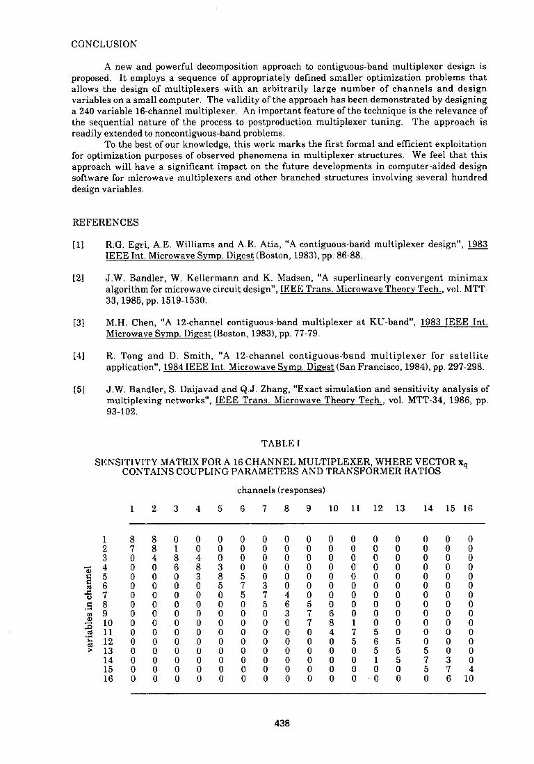
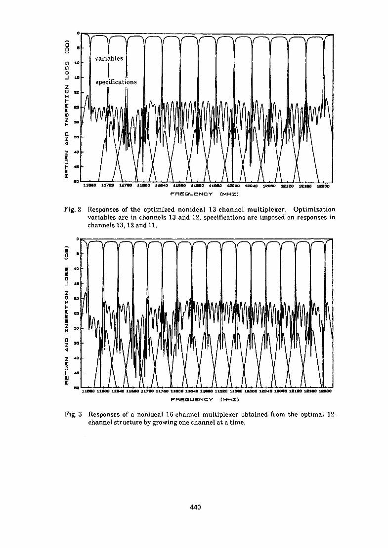
The responses of the multiplexer after adding channel 13 without optimizing it are shownin Fig. 1. Fig. 2 shows the 13-channel multiplexer optimized according to the rules describedearlier, i.e., using only variables in channels 13 and 12 with specifications on responses inchannels 13, 12 and I1. By repeating that process three times we reach the optimal design of a16-channel multiplexer with responses shown in Fig. 3.
437
CONCLUSION
A new and powerful decomposition approach to contiguous-band multiplexer design isproposed. It employs a sequence of appropriately defined smaller optimization problems thatallows the design of multiplexers with an arbitrarily large number of channels and designvariables on a small computer. The validity of the approach has been demonstrated by designinga 240 variable 16-channel multiplexer. An important feature of the technique is the relevance ofthe sequential nature of the process to postproduction multiplexer tuning. The approach isreadily extended to noncontiguous-band problems.
To the best of our knowledge, this work marks the first formal and efflcient exploitationfor optimization purposes of observed phenomena in multiplexer structures. We feel that thisapproach will have a significant impact on the future developments in computer-aided designsoftware for microwave multiplexers and other branched structures involving several hundreddesign variables.
REFERENCES
[1] R.G. Egri, A.E. Williams and A.E. Atia, "A contiguous-band multiplexer design", 1983IEEE Int. Microwave Symp. Digest (Boston, 1983), pp. 86-88.
[21 J.W. Bandler, W. Kellermann and K. Madsen, "A superlinearly convergent minimaxalgorithm for microwave circuit design", IEEE Trans. Microwave Theory Tech., vol. MTT-33, 1985, pp. 1519-1530.
[31 M.H. Chen, "A 12-channel contiguous-band multiplexer at KU-band", 1983 IEEE mnt.Microwave Symp. Digest (Boston, 1983), pp. 77-79.
[4] R. Tong and D. Smith, "A 12-channel contiguous-band multiplexer for satelliteapplication", 1984 IEEE Int. Microwave Symp. Digest (San Francisco, 1984), pp. 297-298.
[51 J.W. Bandler, S. Daijavad and Q.J. Zhang, "Exact simulation and sensitivity analysis ofmultiplexing networks", IEEE Trans. Microwave Theory Tech., vol. MTT-34, 1986, pp.93-102.
TABLE [
SENSITIVITY MATRIX FOR A 16 CHANNEL MULTIPLEXER, WHERE VECTOR xqCONTAINS COUPLING PARAMETERS AND TRANSFORMER RATIOS
channels (responses)
1 2 3 4 5 6 7 8 9 10 11 12 13 14 15 16
1 8 8 0 0 0 0 0 0 0 0 0 0 0 0 0 02 7 8 1 0 0 0 0 0 0 0 0 0 0 0 0 03 0 4 8 4 0 0 0 0 0 0 0 0 0 0 0 04 0 0 6 8 3 0 0 0 0 0 0 0 0 0 0 0
s5 0 0 0 3 8 5 0 0 0 0 0 0 0 0 0 0co6 0 0 0 0 5 7 3 0 0 0 0 0 0 0 0 0t7 0 0 0 0 0 5 7 4 0 0 0 0 0 0 0 0.s8 0 0 0 0 0 0 5 6 5 0 0 0 0 0 0 0* 9 0 0 0 0 0 0 0 3 7 6 0 0 0 0 0 0
10 0 0 0 0 0 0 0 0 7 8 1 0 0 0 0 0*s 11 0 0 0 0 0 0 0 0 0 4 7 5 0 0 0 0$ 12 0 0 0 0 0 0 0 0 0 0 5 6 5 0 0 013 0 0 0 0 0 0 0 0 0 0 0 5 5 5 0 014 0 0 0 0 0 0 0 0 0 0 0 1 5 7 3 015 0 0 0 0 0 0 0 0 0 0 0 0 0 5 7 416 0 0 0 0 0 0 0 0 0 0 0 0 0 0 6 10
438

TABLE II
SENSITIVITY MATRIX FOR A 16 CHANNEL MULTIPLEXER, WHERE VECTOR xqCONTAINS THE DISTANCE FROM THE SHORT CIRCUIT
channels (responses)
1 2 3 4 5 6 7 8 9 10 11 12 13
8 8 0 0 0 07 8 0 0 0 01 2 3 2 0 00 0 4 6 2 00 0 0 4 6 30 0 0 0 5 70 0 0 0 0 40 0 0 0 0 10 0 0 0 0 00 0 0 0 0 0o o 0 0 0 00 0 0 0 0 00 0 0 0 0 00 0 .0 0 0 00 0 0 0 0 00 0 0 0 0 0
0 00 00 00 00 02 06 23 50 30 00 00 00 00 00 00 0
0 00 00 10 10 10 10 23 24 44 70 10 00 00 00 00 0
0 00 01 21 11 01 01 02 01 03 03 53 60 50 20 00 0
_P%
m0
m
in
0
z0
H
F-EE
zH
4
Er
23
FREQUENCY (MHZ)
Fig. 1 Responses of nonideal 12-channel multiplexer with optimized spacings, input-output transformer ratios, cavity resonances and coupling parameters afteradding channel 13 without optimizing it.
439
14 15 16
1234
5rn6X.789
B 10. 11'6 12
13141516
0021000000335510
0021000010335550
0 00 00 00 00 00 00 00 00 00 00 00 00 02 16 47 7r 0 - W
flu
variables53310 I
0speciflcations
w5)2 soH
Z F048
11860 11720 11750 11800 11840 11660 11920 11950 12000 120,40 12080 12120 12180 12200FREQUENCY (MHz)
Fig. 2 Responses of the optimized nonideal 13-channel multiplexer. Optimizationvariables are in channels 13 and 12, specifications are imposed on responses inchannels 13, 12 and Ii1.
0
D1isSC118010180160172 16 10 14 160190190100100o26 22 26 20
H ~ ~ ~ ~ ~ FEQEC MZ
Fi.3Rsossoanoiel1-hnemutpeeobandfothopia12chne trcueb goigon hne a ie
440