creating a better tomorrow through innovative solutions
TRANSCRIPT

C R Y O C O O L E R P R O D U C T C A T A L O G U E
Creating a Better Tomorrow Through Innovative Solutions

2
Sumitomo Heavy Industries, Ltd. (SHI) has a tradition of excellence and innovation that spans over 400 years. From its very beginning as a small shop selling medicines and books in Kyoto, Japan, in the early 17th century, to its current status as a diverse, $8 billion corporation, SHI has continued to grow and flourish in an ever-changing international market.
SHI’s acquisition of IGC-APD Cryogenics, Inc. in 2002 brought together two of the world’s leading cryogenic companies to form the SHI Cryogenics Group, with an unsurpassed tradition of design, development and success in the manufacture of cryogenic equipment.
SHI Cryocoolers continue this tradition by supporting both global research & development, as well as state-of-the-art technologies. Today, applications of cryogenic technologies can be found in our daily lives.
An Overview
Precursor to APD Cryogenics established as Space and Missile Department of Air Products in Allentown, Pennsylvania, USA
1959
APD introduces Displex® cryocooler systems
1968
Air Products’ Space and Missile Department renamed the Advanced Product Development Department (APD)
1962
Sumitomo establishes its cryogenics business at the Hiratsuka Research Laboratory in Hiratsuka City, near Tokyo
1962
3
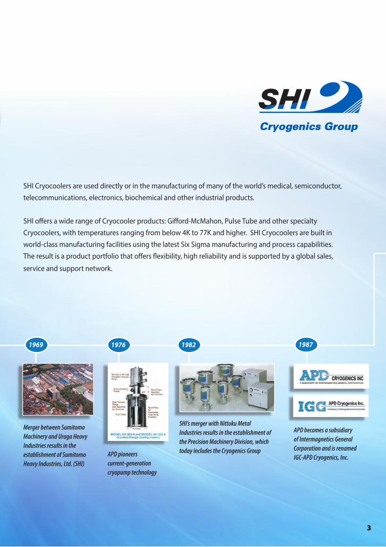
APD pioneers current-generation cryopump technology
1976
Merger between Sumitomo Machinery and Uraga Heavy Industries results in the establishment of Sumitomo Heavy Industries, Ltd. (SHI)
1969
SHI’s merger with Nittoku Metal Industries results in the establishment of the Precision Machinery Division, which today includes the Cryogenics Group
1982
APD becomes a subsidiary of Intermagnetics General Corporation and is renamed IGC-APD Cryogenics, Inc.
1987
SHI Cryocoolers are used directly or in the manufacturing of many of the world’s medical, semiconductor, telecommunications, electronics, biochemical and other industrial products.
SHI offers a wide range of Cryocooler products: Gifford-McMahon, Pulse Tube and other specialty Cryocoolers, with temperatures ranging from below 4K to 77K and higher. SHI Cryocoolers are built in world-class manufacturing facilities using the latest Six Sigma manufacturing and process capabilities. The result is a product portfolio that offers flexibility, high reliability and is supported by a global sales,
service and support network.

4
An Overview, cont.
SHI opens Sumitomo (SHI) Cryogenics of America, Inc. (SCAI) near Chicago, IL, USA, the first Cryogenics Group office in the United States.
1999
SHI opens Sumitomo (SHI) Cryogenics of Europe GmbH (SCEG) in Darmstadt, Germany, the first Cryogenics Group office in Europe.
2000
SHI opens SHI Manufacturing & Services (Philippines), Inc. (SHIms) in Batangas, Philippines.
2001
Sumitomo (SHI) Cryogenics Korea Co., Ltd. (SCKL) opens in Suwon City, South Korea.
2008
SHI develops a separated valve unit option for pulse tube models. This technology further reduces vibration, enables operation in higher magnetic fields and eases maintenance requirements.
2011
Sumitomo (SHI) Cryogenics Taiwan Co., Ltd. (SCTW) opens in Hsinchu City, Taiwan.
2012
Sumitomo (SHI) Cryogenics of America, Inc. opens its fourth and fifth offices in Austin, TX and Malta, NY.
2013
SHI begins designing and manufacturing 4K GM Cryocoolers for MRI applications
1996
5
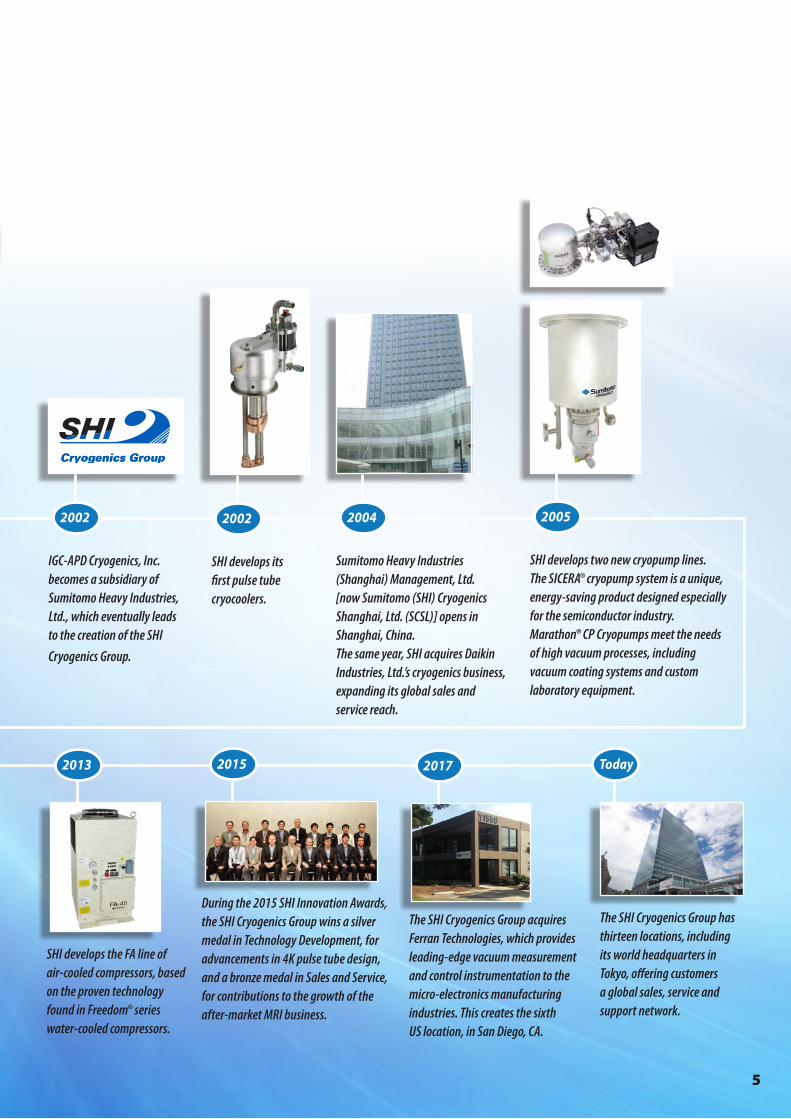
The SHI Cryogenics Group has thirteen locations, including its world headquarters in Tokyo, offering customers a global sales, service and support network.
Today
IGC-APD Cryogenics, Inc. becomes a subsidiary of Sumitomo Heavy Industries, Ltd., which eventually leads to the creation of the SHI
Cryogenics Group.
2002
SHI develops its first pulse tube cryocoolers.
2002
Sumitomo Heavy Industries (Shanghai) Management, Ltd. [now Sumitomo (SHI) Cryogenics Shanghai, Ltd. (SCSL)] opens in Shanghai, China.The same year, SHI acquires Daikin Industries, Ltd.’s cryogenics business, expanding its global sales and service reach.
2004
SHI develops two new cryopump lines. The SICERA® cryopump system is a unique, energy-saving product designed especially for the semiconductor industry. Marathon® CP Cryopumps meet the needs of high vacuum processes, including vacuum coating systems and custom laboratory equipment.
2005
SHI develops the FA line of air-cooled compressors, based on the proven technology found in Freedom® series water-cooled compressors.
2013
During the 2015 SHI Innovation Awards, the SHI Cryogenics Group wins a silver medal in Technology Development, for advancements in 4K pulse tube design, and a bronze medal in Sales and Service, for contributions to the growth of the after-market MRI business.
2015
The SHI Cryogenics Group acquires Ferran Technologies, which provides leading-edge vacuum measurement and control instrumentation to the micro-electronics manufacturing industries. This creates the sixth US location, in San Diego, CA.
2017

6
Cold Head Model RDK-101D(L) RDK-305D RDK-205D RDK-408D2 RDE-412D4 RDK-415D RDE-418D4
2nd Stage Capacity
50 Hz 0.16 W @ 4.2 K1 0.4 W @ 4.2 K 0.5 W @ 4.2 K 1.0 W @ 4.2 K 1.25 W @ 4.2 K 1.5 W @ 4.2 K 1.8 W @ 4.2 K
60 Hz 0.2 W @ 4.2 K1 0.4 W @ 4.2 K 0.5 W @ 4.2 K 1.0 W @ 4.2 K 1.25 W @ 4.2 K 1.5 W @ 4.2 K 2.0 W @ 4.2 K
1st Stage Capacity
50 Hz 3.0 W @ 45 K 15 W @ 40 K 10 W @ 50 K 40 W @ 43 K 53 W @ 43 K 35 W @ 50 K 42 W @ 50 K
60 Hz 5.0 W @ 45 K 20 W @ 40 K 13 W @ 50 K 50 W @ 43 K 60 W @ 43 K 45 W @ 50 K 50 W @ 50 K
Minimum Temperature2
<3.0 K (RDK-101D)/<2.3 K (RDK-101DL)
<3.5 K <3.5 K <3.5 K <3.5 K <3.5 K <3.5 K
Cooldown Time (min)2
50 Hz <150 <120 <90 <60 <60 <60 <60
60 Hz <150 <120 <90 <60 <60 <60 <60
Weight 7.2 kg(15.9 lbs.)
16.0 kg(35.3 lbs.)
14.0 kg(30.9 lbs.)
18.0 kg(39.7 lbs.)
20.0 kg(44.1 lbs.)
18.5 kg(40.8 lbs.)
20.0 kg(44.1 lbs.)
Water-Cooled Compressor Options
HC-4E •
CKW-21A •
F-40L/H • • 3
F-50L/H • • • •
F-50SL/H • •
F-70L/H • 3 • •
Air-Cooled Compressor Options
CNA-11 •
Zephyr® •
FA-40L/H • • 3
CSA-71A • • • •
FA-70L/H • •
1 With CNA-11 Compressor, 2nd stage capacity is 0.1 W @ 4.2 K (50/60 Hz). 1st stage capacity is 3.0/5.0 W @ 60 K (50/60 Hz).2 Lowest temperature and cooldown time are for reference only. However, lowest temperature for RDK-101DL is guaranteed.3 Reduced capacities when operated with F-40, F-70 or FA-40 Compressors. Please contact SHI for more details.4 Up to two (2) cold heads can be operated with the F-70 Compressor.
Specifications subject to change without notice.
4K Cryocoolers
7
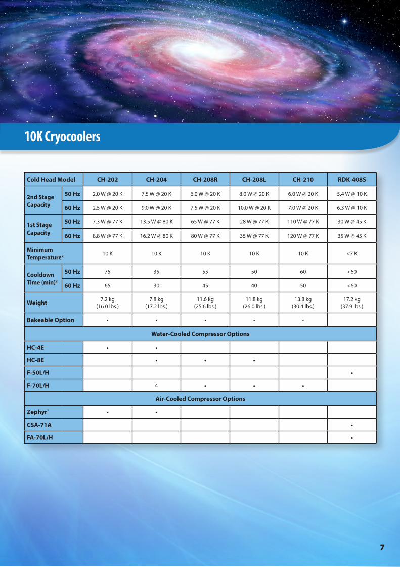
10K Cryocoolers
Cold Head Model CH-202 CH-204 CH-208R CH-208L CH-210 RDK-408S
2nd Stage Capacity
50 Hz 2.0 W @ 20 K 7.5 W @ 20 K 6.0 W @ 20 K 8.0 W @ 20 K 6.0 W @ 20 K 5.4 W @ 10 K
60 Hz 2.5 W @ 20 K 9.0 W @ 20 K 7.5 W @ 20 K 10.0 W @ 20 K 7.0 W @ 20 K 6.3 W @ 10 K
1st Stage Capacity
50 Hz 7.3 W @ 77 K 13.5 W @ 80 K 65 W @ 77 K 28 W @ 77 K 110 W @ 77 K 30 W @ 45 K
60 Hz 8.8 W @ 77 K 16.2 W @ 80 K 80 W @ 77 K 35 W @ 77 K 120 W @ 77 K 35 W @ 45 K
Minimum Temperature2 10 K 10 K 10 K 10 K 10 K <7 K
Cooldown Time (min)2
50 Hz 75 35 55 50 60 <60
60 Hz 65 30 45 40 50 <60
Weight 7.2 kg(16.0 lbs.)
7.8 kg(17.2 lbs.)
11.6 kg(25.6 lbs.)
11.8 kg(26.0 lbs.)
13.8 kg(30.4 lbs.)
17.2 kg(37.9 lbs.)
Bakeable Option • • • • •
Water-Cooled Compressor Options
HC-4E • •
HC-8E • • •
F-50L/H •
F-70L/H 4 • • •
Air-Cooled Compressor Options
Zephyr® • •
CSA-71A •
FA-70L/H •
8
1 Lowest temperature and cooldown time are for reference only. 2 Up to two (2) cold heads can be operated with the F-70 Compressor.3 Reduced capacities when operated with Zephyr, HC-4E or HC-8E Compressors.4 Reduced capacities when operated with FA-70 Compressor. 5 RDK-500B operates with F-70LP and F-70H Compressors.
Specifications subject to change without notice.
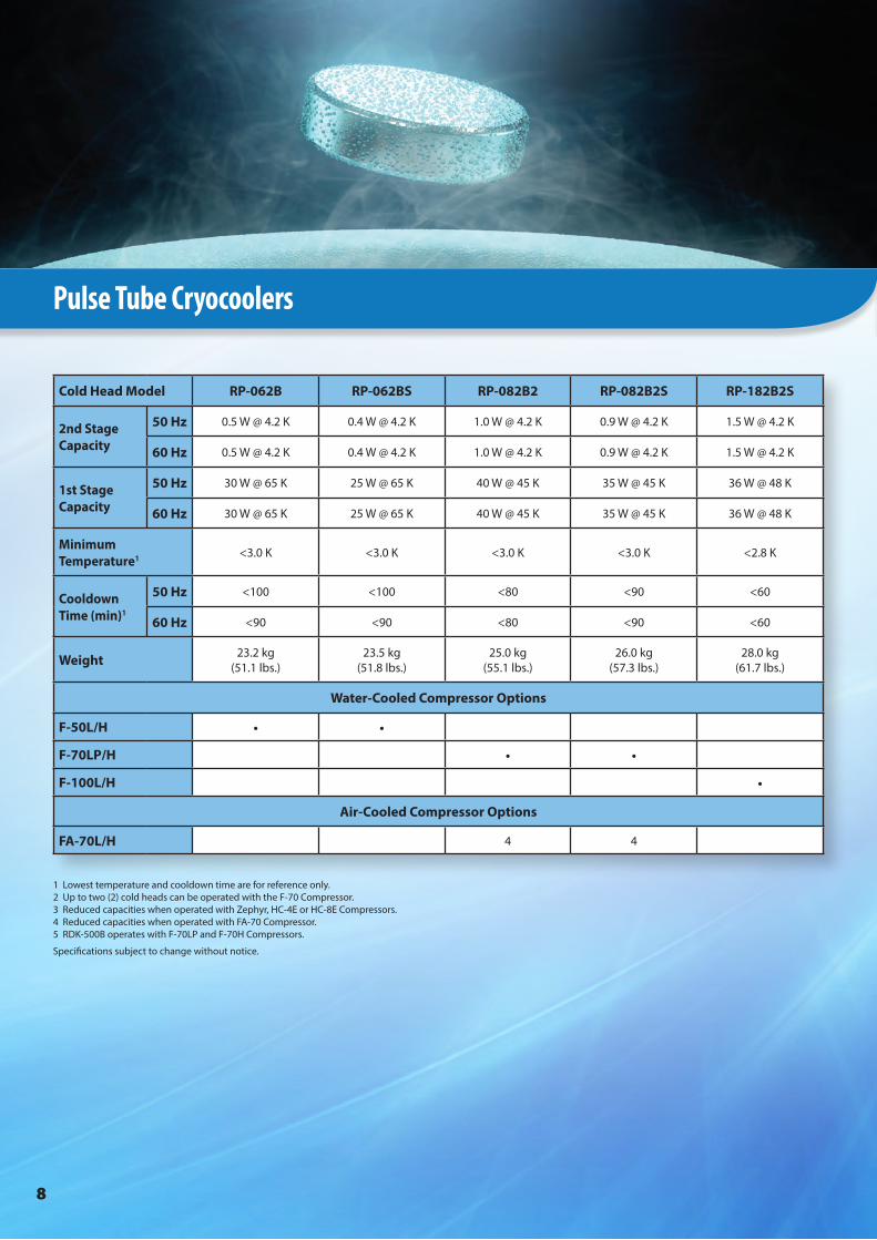
Cold Head Model RP-062B RP-062BS RP-082B2 RP-082B2S RP-182B2S
2nd Stage Capacity
50 Hz 0.5 W @ 4.2 K 0.4 W @ 4.2 K 1.0 W @ 4.2 K 0.9 W @ 4.2 K 1.5 W @ 4.2 K
60 Hz 0.5 W @ 4.2 K 0.4 W @ 4.2 K 1.0 W @ 4.2 K 0.9 W @ 4.2 K 1.5 W @ 4.2 K
1st Stage Capacity
50 Hz 30 W @ 65 K 25 W @ 65 K 40 W @ 45 K 35 W @ 45 K 36 W @ 48 K
60 Hz 30 W @ 65 K 25 W @ 65 K 40 W @ 45 K 35 W @ 45 K 36 W @ 48 K
Minimum Temperature1 <3.0 K <3.0 K <3.0 K <3.0 K <2.8 K
Cooldown Time (min)1
50 Hz <100 <100 <80 <90 <60
60 Hz <90 <90 <80 <90 <60
Weight 23.2 kg(51.1 lbs.)
23.5 kg(51.8 lbs.)
25.0 kg(55.1 lbs.)
26.0 kg(57.3 lbs.)
28.0 kg(61.7 lbs.)
Water-Cooled Compressor Options
F-50L/H • •
F-70LP/H • •
F-100L/H •
Air-Cooled Compressor Options
FA-70L/H 4 4
Pulse Tube Cryocoolers

9
Specialty Cryocoolers
Cold Head Model CH-204-N CH-210-N CH-210L RDK-400B RDK-500B RD-125D CH-104 CH-110 CH-110LT
2nd Stage Capacity
50 Hz 2.5 W @ ≤10 K — 9.5 W @ 20 K — — — — — —
60 Hz 3.0 W @ ≤10 K 3.0 W @ 10 K 11 W @ 20 K — — — — — —
1st Stage Capacity
50 Hz — — 75 W @ 60 K 54 W @ 40 K 40 W @ 20 K80 W @ 30 K 30 W @ 77 K 34 W @ 77 K 175 W @ 77 K 80 W @ 40 K
60 Hz — 20 W @ 35 K 90 W @ 60 K 70 W @ 40 K 45 W @ 20 K94 W @ 30 K 30 W @ 77 K 42 W @ 77 K 200 W @ 77 K 95 W @ 40 K
Minimum Temperature1 6.5 K 10 K 10 K <25 K <14 K <30 K ≤40 K ≤40 K <15 K
Cooldown Time (min)1
50 Hz 40 — <60 <30 <70 <25 <40 <35 <35
60 Hz 35 60 <60 <30 <70 <25 <30 <30 <30
Weight 7.8 kg(17.2 lbs.)
13.8 kg(30.4 lbs.)
12.1 kg(26.7 lbs.)
16.0 kg(35.3 lbs.)
25.0 kg(55.1 lbs.)
15.0 kg(33.1 lbs.)
7.9 kg(17.5 lbs.)
13.7 kg(30.2 lbs.)
13.8 kg(30.5 lbs.)
Bakeable Option • • • • • •
Water-Cooled Compressor Options
HC-4E • • 3
HC-8E • • 3
F-50L/H •
F-70L(P)/H 2 • • 5 2 • •
Air-Cooled Compressor Options
CNA-11 •
Zephyr® • • 3
CSA-71A •
FA-70L/H • • •
10
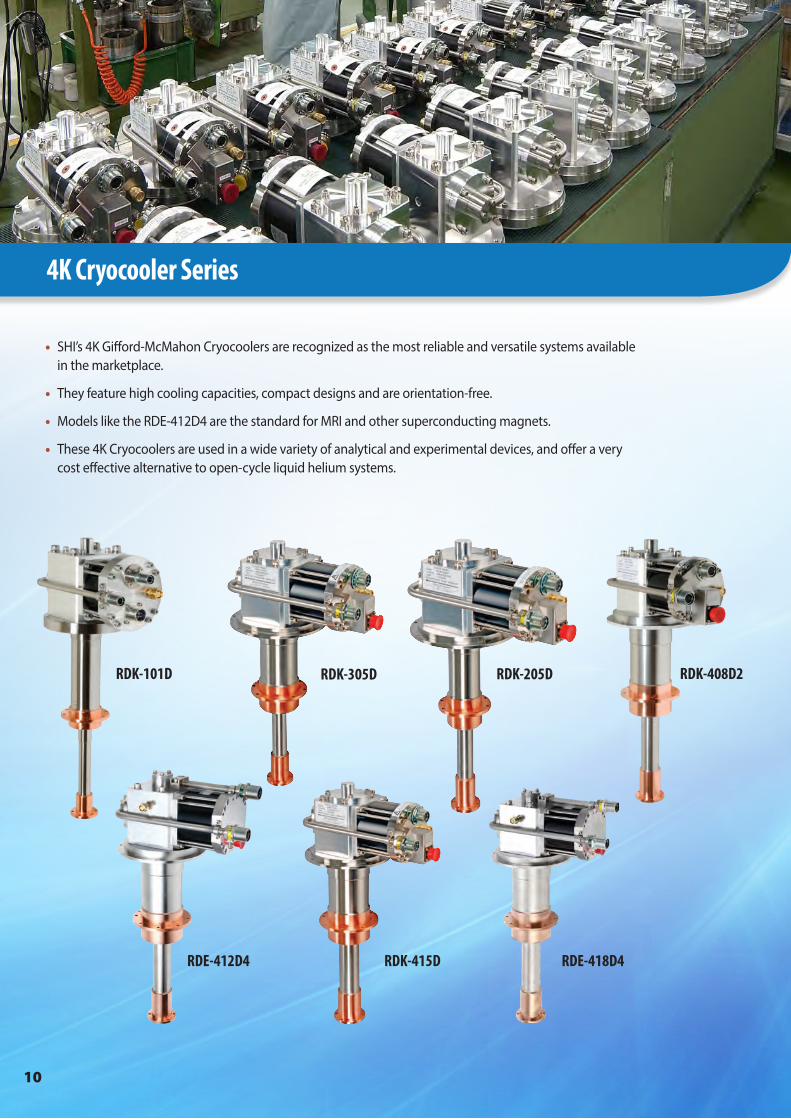
4K Cryocooler Series
• SHI’s 4K Gifford-McMahon Cryocoolers are recognized as the most reliable and versatile systems available in the marketplace.
• They feature high cooling capacities, compact designs and are orientation-free.
• Models like the RDE-412D4 are the standard for MRI and other superconducting magnets.
• These 4K Cryocoolers are used in a wide variety of analytical and experimental devices, and offer a very cost effective alternative to open-cycle liquid helium systems.
RDK-101D RDK-205DRDK-305D RDK-408D2
RDE-412D4 RDK-415D RDE-418D4

11
Performance Specifications
Power Supply 50Hz 60 Hz
2nd Stage Capacity 0.4 W @ 4.2 K
1st Stage Capacity 15 W @ 40 K 20 W @ 40 K
Minimum Temperature1 <3.5 K
Cooldown Time to 4.2 K1 <120 Minutes
Weight 16.0 kg (35.3 lbs.)
Dimensions (HxWxD) 512 x 180 x 294 mm (20.2 x 7.1 x 11.6 in.)
Maintenance 10,000 Hours
Regulatory Compliance UL/CE, RoHS
Standard Scope of Supply• RDK-305D Cold Head• F-40L/H or FA-40L/H
Compressor• Helium Gas Lines – 10 m (33 ft.) • Cold Head Cable – 10 m (33 ft.) • Power Cable – 3-6 m (10-20 ft.)2
or 2-8 m (6-27 ft.)3• Tool Kit
1 Lowest temperature and cooldown time are for reference only. 2 With F-40L and FA-40L3 With F-40H and FA-40H
RDK-305D 4K Cryocooler Series
Performance Specifications
Power Supply 50Hz 60 Hz
2nd Stage Capacity1 0.16 W @ 4.2 K 0.2 W @ 4.2 K
1st Stage Capacity1 3.0 W @ 45 K 5.0 W @ 45 K
Minimum Temperature2 3.0 K (RDK-101D)/<2.3 K (RDK-101DL)
Cooldown Time to 4.2 K2 <150 Minutes
Weight 7.2 kg (15.9 lbs.)
Dimensions (HxWxD) 442 x 130 x 226 mm(17.4 x 5.1 x 8.9 in.)
Maintenance 10,000 Hours
Regulatory Compliance UL/CE, RoHS
Standard Scope of Supply• RDK-101D(L) Cold Head• HC-4E, CNA-11B/C or Zephyr®
Compressor• Helium Gas Lines – 3 m (10 ft.)3 or
3-20 m (10-66 ft.)4• Cold Head Cable – 6 m (20 ft.)3 or
3.5-20 m (11-66 ft.)4• Power Cable – 5 m (16.5 ft.)3• Tool Kit
1 With CNA-11B/C compressors, 2nd stage capacity is 0.1 W @ 4.2 K (50/60 Hz). 1st stage capacity is 3.0/5.0 W @ 60 K (50/60 Hz).2 Lowest temperature and cooldown time are for reference only. However, lowest temperature for RDK-101DL is guaranteed.3 With CNA-11B/C4 With HC-4E or Zephyr®
RDK-101D 4K Cryocooler Series1s
t Sta
ge
Hea
t Lo
ad
0.2W
0.1W
0.4W
0.3W
0W
0W
3W
2nd Stage Heat Load2.0
3.0
4.0
5.0
6.0
2nd
Sta
ge T
emp
erat
ure
[K]
27 29 31 33 351st Stage Temperature [K]
SRDK-101D Cold Head Capacity Map (50 Hz)With Zephyr® Compressor and 3 m (10 ft.) Helium Gas Lines
RDK-101D Cold Head Capacity Map (50 Hz)With Zephyr® Compressor and 3 m (10 ft.) Helium Gas Lines
1st S
tag
e H
eat
Load
0.2W0.1W
0.4W
0.3W
0W
0W
3W 5W
2nd Stage Heat Load2.0
3.0
4.0
5.0
6.0
2nd
Sta
ge T
emp
erat
ure
[K]
30 3432 3836 4240 441st Stage Temperature [K]
SRDK-101D Cold Head Capacity Map (60 Hz)With Zephyr® Compressor and 3 m (10 ft.) Helium Gas Lines
RDK-101D Cold Head Capacity Map (60 Hz)With Zephyr® Compressor and 3 m (10 ft.) Helium Gas Lines
1st S
tag
e H
eat
Load
0.4W
0W
0.2W0W 15W
0.6W
30W
2nd Stage Heat Load2.0
2.5
3.0
3.5
4.0
4.5
2nd
Sta
ge T
emp
erat
ure
[K]
20 25 30 35 45401st Stage Temperature [K]
SRDK-305D Cold Head Capacity Map (50 Hz)With FA-40 Compressor and 10 m (33 ft.) Helium Gas Lines
1st S
tag
e H
eat
Load 0.4W
0W
0.2W
0W20W
0.6W
40W
2nd Stage Heat Load
2.5
3.0
3.5
4.0
4.5
2nd
Sta
ge T
emp
erat
ure
[K]
20 25 30 35 40 451st Stage Temperature [K]
SRDK-305D Cold Head Capacity Map (60 Hz)With FA-40 Compressor and 10 m (33 ft.) Helium Gas Lines
RDK-305D Cold Head Capacity Map (50 Hz)With FA-40 Compressor and 10 m (35 ft.) Helium Gas Lines
RDK-305D Cold Head Capacity Map (60 Hz)With FA-40 Compressor and 10 m (35 ft.) Helium Gas Lines
Note: Capacity maps for reference only

12
Performance Specifications
Power Supply 50Hz 60 Hz
2nd Stage Capacity 0.5 W @ 4.2 K
1st Stage Capacity 10 W @ 50 K 13 W @ 50 K
Minimum Temperature1 <3.5 K
Cooldown Time to 4.2 K1 <90 Minutes
Weight 14.0 kg (30.9 lbs.)
Dimensions (HxWxD) 512 x 180 x 294 mm(20.2 x 7.1 x 11.6 in.)
Maintenance 10,000 Hours
Regulatory Compliance UL/CE, RoHS
Standard Scope of Supply• RDK-205D Cold Head• CKW-21A, F-40L/H or FA-40L/H
Compressor• Helium Gas Lines – 10 m (32 ft.) • Cold Head Cable – 10 m (32 ft.) • Power Cable – 10 m (33 ft.)2, 3-6 m
(10-20 ft.)3 or 2-8 m (6-27 ft.)4• Hose Nipples2
• Tool Kit1 Lowest temperature and cooldown time are for reference only.2 With CKW-21A 3 With F-40L and FA-40L4 With F-40H and FA-40H
RDK-205D 4K Cryocooler Series
24 26 28 30 3432 36 381st Stage Temperature [K]
2.8
3.0
3.2
3.4
3.6
3.8
4.0
4.2
2nd
Sta
ge T
emp
erat
ure
[K]
1st S
tag
e H
eat
Load
0.5W
0W
0.4W0.3W
0W 8W6W4W
0.7W
2W 12W10W
0.6W
2nd Stage Heat Load
SRDK-205D Cold Head Capacity Map (60 Hz)With F-40 Compressor and 10 m (33 ft.) Helium Gas Lines
RDK-205D Cold Head Capacity Map (60 Hz)With F-40 Compressor and 10 m (33 ft.) Helium Gas Lines
26 30 34 38 42 46 501st Stage Temperature [K]
2.7
2.9
3.1
3.3
3.5
3.7
4.1
3.9
4.3
2nd
Sta
ge T
emp
erat
ure
[K]
1st S
tag
e H
eat
Load
0.5W
0W
0.4W
0.3W
0W 8W6W4W
0.7W
2W 12W10W
0.6W
2nd Stage Heat Load
SRDK-205D Cold Head Capacity Map (50 Hz)With F-40 Compressor and 10 m (33 ft.) Helium Gas Lines
RDK-205D Cold Head Capacity Map (50 Hz)With F-40 Compressor and 10 m (33 ft.) Helium Gas Lines
Performance Specifications
Power Supply 50Hz 60 Hz
2nd Stage Capacity 1.0 W @ 4.2 K
1st Stage Capacity 40 W @ 43 K 50 W @ 43 K
Minimum Temperature1 <3.5 K
Cooldown Time to 4.2 K1 <60 Minutes
Weight 18.0 kg (39.7 lbs.)
Dimensions (HxWxD) 557 x 180 x 294 mm (21.9 x 7.1 x 11.6 in.)
Maintenance 10,000 Hours
Regulatory Compliance UL/CE, RoHS
RDK-408D2 4K Cryocooler Series
Standard Scope of Supply• RDK-408D2 Cold Head• F-50L/H, F-70L/H, CSA-71A or
FA-70L/H Compressor• Helium Gas Lines – 6 m (20 ft.)2,3,4,5; or
10 m (33 ft.) [IDU] + 10 m (33 ft.), 20 m (66 ft.) or 30 m (99 ft.) [ODU]6
• Cold Head Cable –6-20 m (20-66 ft.)• Power Cable – 5 m (16.5 ft.)2,5; 3-6 m
(10-20 ft.)3; 2-8 m (6-27 ft.)4; or 5 m (16.5 ft.) [IDU] + 10 m (33 ft.), 20 m (66 ft.) or 30 m (99 ft.) [ODU]6
• Hose Nipples2
• Tool Kit
1 Lowest temperature and cooldown time are for reference only. 2 With F-503 With F-70L4 With F-70H5 With CSA-71A6 With FA-70
RDK-408D2 Cold Head Capacity Map (50 Hz)With F-50 Compressor and 6 m (20 ft.) Helium Gas Lines
RDK-408D2 Cold Head Capacity Map (60 Hz)With F-50 Compressor and 6 m (20 ft.) Helium Gas Lines
20 30 40 50 60 70 801st Stage Temperature [K]
26
10141822263034384246
2nd
Sta
ge T
emp
erat
ure
[K]
1st S
tag
e H
eat
Load
15W
1W0W
8W4W
0W60W40W
20W20W80W
2nd Stage Heat Load
SRDK-408D2 Cold Head Capacity Map (50 Hz)With F-50 Compressor and 6 m (20 ft.) Helium Gas Lines
20 30 40 50 60 701st Stage Temperature [K]
26
1014182226303438
2nd
Sta
ge T
emp
erat
ure
[K]
1st S
tage
H
eat L
oad
15W
1W0W
8W4W
0W
60W40W20W
20W80W
2nd Stage Heat Load
SRDK-408D2 Cold Head Capacity Map (60 Hz)With F-50 Compressor and 6 m (20 ft.) Helium Gas Lines

13
Performance Specifications
Power Supply 50Hz 60 Hz
2nd Stage Capacity 1.5 W @ 4.2 K
1st Stage Capacity 35 W @ 50 K 45 W @ 50 K
Minimum Temperature1 <3.5 K
Cooldown Time to 4.2 K1 <60 Minutes
Weight 18.5 kg (40.8 lbs.)
Dimensions (HxWxD) 557 x 180 x 294 mm (21.9 x 7.1 x 11.6 in.)
Maintenance 10,000 Hours
Regulatory Compliance UL/CE, RoHS
Standard Scope of Supply• RDK-415D Cold Head• F-50L/H, F-70L/H, CSA-71A or
FA-70L/H Compressor• Helium Gas Lines – 20 m (66 ft.)2,3,4,5;
6 m (20 ft.) with Buffer Tank2,5; or 10 m (33 ft.) [IDU] + 10 m (33 ft.), 20 m (66 ft.) or 30 m (99 ft.) [ODU]6
• Cold Head Cable –6-20 m (20-66 ft.)• Power Cable – 5 m (16.5 ft.)2,5; 3-6 m
(10-20 ft.)3; 2-8 m (6-27 ft.)4; or 5 m (16.5 ft.) [IDU] + 10 m (33 ft.), 20 m (66 ft.) or 30 m (99 ft.) [ODU]6
• Hose Nipples2• Tool Kit
RDK-415D 4K Cryocooler Series
Performance Specifications
Power Supply 50Hz 60 Hz
2nd Stage Capacity1 1.25 W @ 4.2 K
1st Stage Capacity1 53 W @ 43 K 60 W @ 43 K
Minimum Temperature2 <3.5 K
Cooldown Time to 4.2 K2 <60 Minutes
Weight 20.0 kg (44.1 lbs.)
Dimensions (HxWxD) 554 x 180 x 306 mm(21.8 x 7.1 x 12.0 in.)
Maintenance 10,000 Hours
Regulatory Compliance UL/CE, RoHS
Standard Scope of Supply• RDE-412D4 Cold Head• F-40L/H, F-50L/H, F-50SL/H, F-70L/H,
FA-40L/H or CSA-71A Compressor• Helium Gas Lines – 20 m (65 ft.)3,6,7
or 6 m (20 ft.) with Buffer Tank4,5
• Cold Head Cable – 20 m (65 ft.)3 or 6-20 m (20-66 ft.)4,5,6,7
• Power Cable – 3 m (10 ft.)3, 5 m (16.5 ft.)4,5, 3-6 m (10-20 ft.)6 or 2-8 m (6-27 ft.)7
• Hose Nipples3,4
• Tool Kit
RDE-412D4 4K Cryocooler Series
25 35 45 55 65 75 851st Stage Temperature [K]
0
4
8
12
16
20
24
28
2nd
Sta
ge T
emp
erat
ure
[K]
2n
d S
tag
e H
eat
Load
1st Stage Heat Load
SRDE-412D4 Cold Head Capacity Map (50 Hz)With F-50 Compressor and 20 m (66 ft.) Helium Gas Lines
8W
1.25W
20W
15W0W
0W
20W 40W 60W 80W
RDE-412D4 Cold Head Capacity Map (50 Hz)With F-50 Compressor and 20 m (66 ft.) Helium Gas Lines
SRDE-412D4 Cold Head Capacity Map (60 Hz)With F-50 Compressor and 20 m (66 ft.) Helium Gas Lines
25 35 45 55 651st Stage Temperature [K]
0
5
10
15
20
25
30
35
2nd
Sta
ge T
emp
erat
ure
[K]
8W
1.25W
20W
15W0W
0W
20W 40W 60W 80W
2n
d S
tag
e H
eat
Load
1st Stage Heat Load
RDE-412D4 Cold Head Capacity Map (60 Hz)With F-50 Compressor and 20 m (66 ft.) Helium Gas Lines
1st S
tag
e H
eat
Load
15W
1.5W0W
10W
5W
0W 60W40W
20W
20W
80W
2nd Stage Heat Load0
2468
101214161820
2nd
Sta
ge T
emp
erat
ure
[K]
20 30 40 50 60 70 80 90 100 110 1201st Stage Temperature [K]
SRDK-415D Cold Head Capacity Map (50 Hz)With F-50 Compressor and 20 m (66 ft.) Helium Gas Lines
1st S
tag
e H
eat
Load
15W
1.5W
0W
10W
5W
0W 60W40W
20W
20W80W
2nd Stage Heat Load2
4
6
8
10
12
14
16
2nd
Sta
ge T
emp
erat
ure
[K]
20 30 40 50 60 70 80 90 1001st Stage Temperature [K]
SRDK-415D Cold Head Capacity Map (60 Hz)With F-50 Compressor and 20 m (66 ft.) Helium Gas Lines
RDK-415D Cold Head Capacity Map (50 Hz)With F-50 Compressor and 20 m (66 ft.) Helium Gas Lines
RDK-415D Cold Head Capacity Map (60 Hz)With F-50 Compressor and 20 m (66 ft.) Helium Gas Lines
1 Reduced capacities when operated with F-40 or FA-40 Compressors.2 Lowest temperature and cooldown time are for reference only. 3 With F-40 and FA-404 With F-505 With CSA-71A6 With F-70L7 With F-70H
1 Lowest temperature and cooldown time are for reference only. 2 With F-503 With F-70L4 With F-70H5 With CSA-71A6 With FA-70

14
Performance Specifications
Power Supply 50Hz 60 Hz
2nd Stage Capacity 1.8 W @ 4.2 K 2.0 W @ 4.2 K
1st Stage Capacity 42 W @ 50 K 50 W @ 50 K
Minimum Temperature1 <3.5 K
Cooldown Time to 4.2 K1 <60 Minutes
Weight 20.0 kg (44.1 lbs.)
Dimensions (HxWxD) 554 x 180 x 306 mm (21.8 x 7.1 x 12.0 in.)
Maintenance 10,000 Hours
Regulatory Compliance UL/CE, RoHS
Standard Scope of Supply• RDE-418D4 Cold Head• F-50L/H, F-50SL/H or F-70L/H
Compressor• Helium Gas Lines – 20 m (65 ft.)
or 6 m (20 ft.) with Buffer Tank• Cold Head Cable – 6-20 m
(20-66 ft.)2, 20 m (66 ft.)3
• Power Cable – 2 m (6 ft.)3, 5 m (16.5 ft.)2
• Hose Nipples• Tool Kit
RDE-418D4 4K Cryocooler Series2
nd
Sta
ge
Hea
t Lo
ad
15W
1.8W0W
10W
5W
0W 60W40W
20W
20W
80W
1st Stage Heat Load0
5
10
15
20
25
30
35
2nd
Sta
ge T
emp
erat
ure
[K]
20 40 60 80 100 1201st Stage Temperature [K]
SRDE-418D4 Cold Head Capacity Map (50 Hz)With F-50 Compressor and 20 m (66 ft.) Helium Gas Lines
2n
d S
tag
e H
eat
Load
15W
2W0W
10W
5W
0W60W40W
20W
20W
80W
1st Stage Heat Load0
5
10
15
20
25
30
2nd
Sta
ge T
emp
erat
ure
[K]
20 40 60 80 1001st Stage Temperature [K]
SRDE-418D4 Cold Head Capacity Map (60 Hz)With F-50 Compressor and 20 m (66 ft.) Helium Gas Lines
RDE-418D4 Cold Head Capacity Map (50 Hz)With F-50 Compressor and 20 m (66 ft.) Helium Gas Lines
RDE-418D4 Cold Head Capacity Map (60 Hz)With F-50 Compressor and 20 m (66 ft.) Helium Gas Lines
1 Lowest temperature and cooldown time are for reference only. 2 With F-503 With F-70
Tokyo, Japan
Batangas, Philippines
Shanghai, China
Suwon-city, South Korea
Hsinchu-City, Taiwan
SHI Cryogenics Group LocationsAsia
SHI Cryogenics Group LocationsAsia

15
10K Cryocooler Series
• SHI’s 10K Gifford-McMahon Cryocoolers are versatile, closed-cycle systems, with the CH series featuring Displex® technology.
• Displex cryocoolers have been recognized as the industry standard since we developed the technology over 40 years ago.
• Its original pneumatic drive, which limits the number of wear parts in the refrigerator, combined with state-of-the-art design features, results in superior performance and low maintenance costs.
• SHI’s 10K Cryocoolers have proven reliability in thousands of applications, including MRI, cryopumping, research and other custom low temperature applications.
CH-202
CH-208L
CH-208RCH-210
CH-204
RDK-408S

16
Performance Specifications
Power Supply 50Hz 60 Hz
2nd Stage Capacity 2.0 W @ 20 K 2.5 W @ 20 K
1st Stage Capacity 7.3 W @ 77 K 8.8 W @ 77 K
Minimum Temperature1 10 K
Cooldown Time to 20 K1 75 Minutes 65 Minutes
Weight 7.2 kg (16.0 lbs.)
Dimensions (HxD)2 468 x ø133 mm(18.4 x ø5.3 in.)
Maintenance 13,000 Hours
Regulatory Compliance CE
Standard Scope of Supply• CH-202 Cold Head• HC-4E or Zephyr® Compressor• Helium Gas Lines – 3-25 m (10-82 ft.)• Cold Head Cable – 3.5-15 m (11-50 ft.)• Tool Kit
1 Lowest temperature and cooldown time are for reference only. 2 With standard flat warm flange. (Available in other warm flange interfaces.)
CH-202 10K Cryocooler Series
5
10
15
20
2nd
Sta
ge T
emp
erat
ure
[K]
25 30 35 40 45 50 55 601st Stage Temperature [K]
1st S
tag
e H
eat
Load
2nd Stage Heat Load
7W
0W
2.5W7W
5W0W 3W 11W
CH-204 Cold Head Capacity Map (50 Hz)With HC-4E2 Compressor and 3 m (10 ft.) Helium Gas Lines
5
10
15
20
25
30
2nd
Sta
ge T
emp
erat
ure
[K]
30 40 50 60 70 80 901st Stage Temperature [K]
1st S
tag
e H
eat
Load
2nd Stage Heat Load
1.5W
0W
5W
0.8W
0W 3W 2.2W
2.8W7W
CH-202 Cold Head Capacity Map (50 Hz)With HC-4E1 Compressor and 3 m (10 ft.) Helium Gas Lines
CH-202 Cold Head Capacity Map (50 Hz)With HC-4E1 Compressor and 3 m (10 ft.) Helium Gas Lines
5
10
15
20
25
2nd
Sta
ge T
emp
erat
ure
[K]
20 30 40 50 60 70 80 901st Stage Temperature [K]
1st S
tag
e H
eat
Load
2nd Stage Heat Load
CH-204 Cold Head Capacity Map (60 Hz)With HC-4E2 Compressor and 3 m (10 ft.) Helium Gas Lines
6W
0W2W
10W
4W
0W 5W25W
8W
20W15W
CH-202 Cold Head Capacity Map (60 Hz)With HC-4E1 Compressor and 3 m (10 ft.) Helium Gas Lines
CH-204 Cold Head Capacity Map (50/60 Hz)With HC-4E2 Compressor and 3 m (10 ft.) Helium Gas Lines
CH-204 Cold Head Capacity Map (60 Hz)With HC-4E2 Compressor and 3 m (10 ft.) Helium Gas Lines
5
10
15
20
25
2nd
Sta
ge T
emp
erat
ure
[K]
20 30 40 50 60 70 80 901st Stage Temperature [K]
1st S
tag
e H
eat
Load
2nd Stage Heat Load
CH-204 Cold Head Capacity Map (60 Hz)With HC-4E2 Compressor and 3 m (10 ft.) Helium Gas Lines
6W
0W2W
10W
4W
0W 5W25W
8W
20W15W
Performance Specifications
Power Supply 50Hz 60 Hz
2nd Stage Capacity 7.5 W @ 20 K 9.0 W @ 20 K
1st Stage Capacity 13.5 W @ 80 K 16.2 W @ 80 K
Minimum Temperature1 10 K
Cooldown Time to 20 K1 35 Minutes 30 Minutes
Weight 7.8 kg (17.2 lbs.)
Dimensions (HxD)2 468 x ø133 mm(18.4 x ø5.3 in.)
Maintenance 13,000 Hours
Regulatory Compliance CE
Standard Scope of Supply• CH-204 Cold Head• HC-4E, HC-8E, F-70L/H or Zephyr®
Compressor3• Helium Gas Lines – 3-25 m (10-82 ft.)• Cold Head Cable – 3.5-15 m (11-50 ft.)4,
3-18 m (10-60 ft.)5 or 3-20 m (10-66 ft.)6,7
• Power Cable – 3-6 m (10-20 ft.)6 or 2-8 m (6-27 ft.)7
• Tool Kit1 Lowest temperature and cooldown time are for reference only. 2 With standard flat warm flange. (Available in other warm flange interfaces.)
CH-204 10K Cryocooler Series
3 Up to two (2) cold heads can be operated with the F-70 Compressor.4 With HC-4E or Zephyr®5 With HC-8E6 With F-70L7 With F-70H

17
Performance Specifications
Power Supply 50Hz 60 Hz
2nd Stage Capacity 6.0 W @ 20 K 7.5 W @ 20 K
1st Stage Capacity 65 W @ 77 K 80 W @ 77 K
Minimum Temperature1 10 K
Cooldown Time to 20 K1 55 Minutes 45 Minutes
Weight 11.6 kg (25.6 lbs.)
Dimensions (HxD) 551 x ø156 mm(21.7 x ø6.1 in.)
Maintenance 13,000 Hours
Regulatory Compliance CE
Standard Scope of Supply• CH-208R Cold Head• HC-8E or F-70L/H Compressor• Helium Gas Lines – 3-25 m (10-82 ft.)• Cold Head Cable –3-18 m (10-60 ft.)2 or
3-20 m (10-66 ft.)3,4
• Power Cable – 3-6 m (10-20 ft.)3 or 2-8 m (6-27 ft.)4
• Tool Kit
1 Lowest temperature and cooldown time are for reference only. 2 With HC-8E3 With F-70L4 With F-70H
CH-208R 10K Cryocooler Series1s
t Sta
ge
Hea
t Lo
ad
6
12
18
24
30
36
2nd
Sta
ge T
emp
erat
ure
[K]
20 30 40 50 60 70 80 901st Stage Temperature [K]
7.5W
0W2W
6W
4W
0W
65W25W
45W
2nd Stage Heat Load
CH-208R Cold Head Capacity Map (50 Hz)With HC-8E4 Compressor and 3 m (10 ft.) Helium Gas Lines
CH-208R Cold Head Capacity Map (50 Hz)With HC-8E4 Compressor and 3 m (10 ft.) Helium Gas Lines
1st S
tag
e H
eat
Load
2nd Stage Heat Load
68
101214161820222426
2nd
Sta
ge T
emp
erat
ure
[K]
20 30 40 50 60 70 80 901st Stage Temperature [K]
0W
0W
20W 40W8W
2W
6W4W
80W60W 90W
CH-208R Cold Head Capacity Map (60 Hz)With HC-8E4 Compressor and 3 m (10 ft.) Helium Gas Lines
CH-208R Cold Head Capacity Map (60 Hz)With HC-8E4 Compressor and 3 m (10 ft.) Helium Gas Lines
Performance Specifications
Power Supply 50Hz 60 Hz
2nd Stage Capacity 8.0 W @ 20 K 10.0 W @ 20 K
1st Stage Capacity 28 W @ 77 K 35 W @ 77 K
Minimum Temperature1 10 K
Cooldown Time to 20 K1 50 Minutes 40 Minutes
Weight 11.8 kg (26.0 lbs.)
Dimensions (HxD) 551 x ø156 mm(21.7 x ø6.1 in.)
Maintenance 13,000 Hours
Regulatory Compliance CE
Standard Scope of Supply• CH-208L Cold Head• HC-8E or F-70L/H Compressor• Helium Gas Lines – 3-25 m (10-82 ft.)• Cold Head Cable –3-18 m (10-60 ft.)2
or 3-20 m (10-66 ft.)3,4
• Power Cable – 3-6 m (10-20 ft.)3 or 2-8 m (6-27 ft.)4
• Tool Kit
1 Lowest temperature and cooldown time are for reference only. 2 With HC-8E3 With F-70L4 With F-70H
CH-208L 10K Cryocooler Series
1st S
tag
e H
eat
Load
9W
0W
3W
5W
7W
5W
0W 35W25W
11W
15W
45W
2nd Stage Heat Load
810121416182022242628
2nd
Sta
ge T
emp
erat
ure
[K]
20 30 40 50 60 70 80 901st Stage Temperature [K]
CH-208L Cold Head Capacity Map (50 Hz)With HC-8E4 Compressor and 3 m (10 ft.) Helium Gas Lines
1st S
tag
e H
eat
Load
2nd Stage Heat Load
8
10
12
14
16
18
20
22
24
2nd
Sta
ge T
emp
erat
ure
[K]
20 30 40 50 60 70 80 901st Stage Temperature [K]
9W
0W3W
10W
7W
0W 35W55W11W
20W45W
CH-208L Cold Head Capacity Map (60 Hz)With HC-8E4 Compressor and 3 m (10 ft.) Helium Gas Lines
CH-208L Cold Head Capacity Map (50 Hz)With HC-8E4 Compressor and 3 m (10 ft.) Helium Gas Lines
CH-208L Cold Head Capacity Map (60 Hz)With HC-8E4 Compressor and 3 m (10 ft.) Helium Gas Lines
18
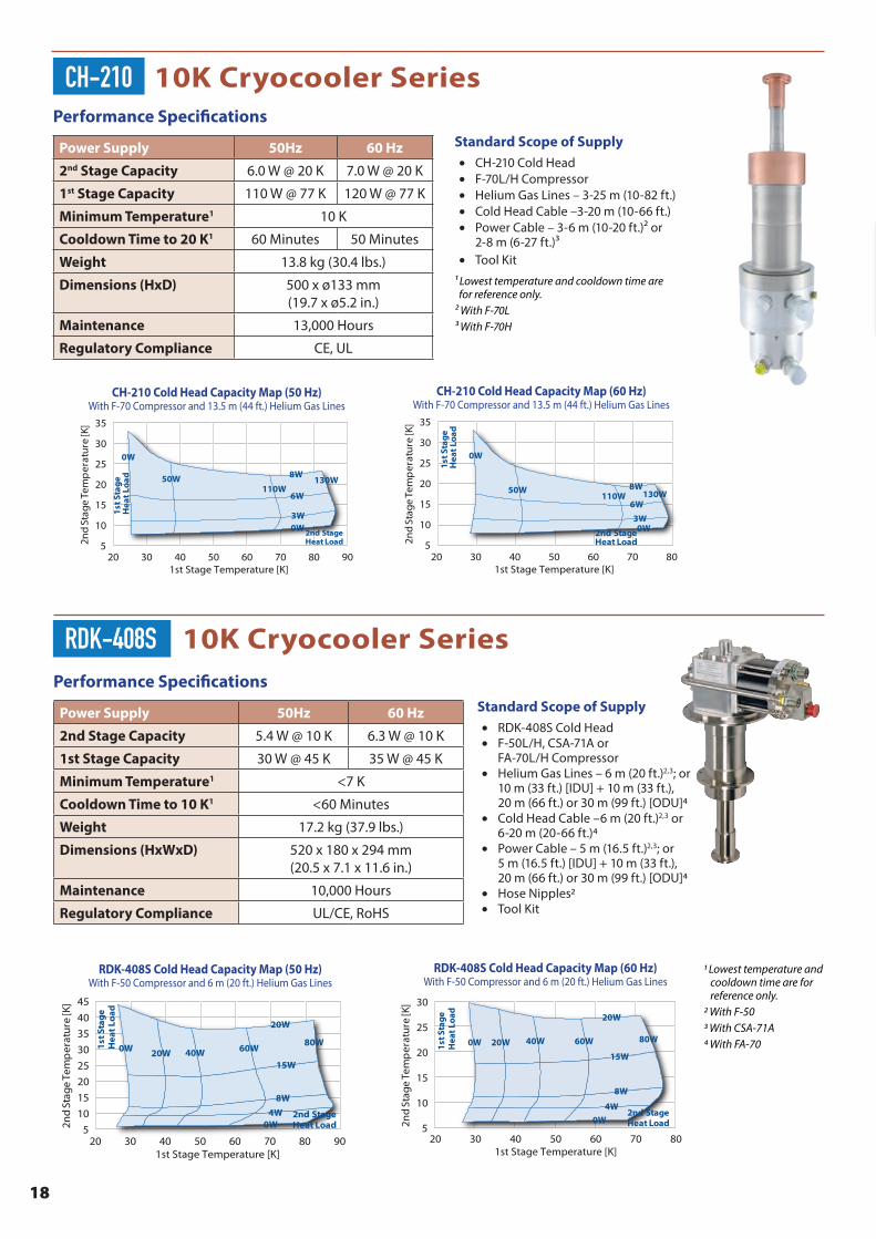
Performance Specifications
Power Supply 50Hz 60 Hz
2nd Stage Capacity 5.4 W @ 10 K 6.3 W @ 10 K
1st Stage Capacity 30 W @ 45 K 35 W @ 45 K
Minimum Temperature1 <7 K
Cooldown Time to 10 K1 <60 Minutes
Weight 17.2 kg (37.9 lbs.)
Dimensions (HxWxD) 520 x 180 x 294 mm (20.5 x 7.1 x 11.6 in.)
Maintenance 10,000 Hours
Regulatory Compliance UL/CE, RoHS
Standard Scope of Supply• RDK-408S Cold Head• F-50L/H, CSA-71A or
FA-70L/H Compressor• Helium Gas Lines – 6 m (20 ft.)2,3; or
10 m (33 ft.) [IDU] + 10 m (33 ft.), 20 m (66 ft.) or 30 m (99 ft.) [ODU]4
• Cold Head Cable –6 m (20 ft.)2,3 or 6-20 m (20-66 ft.)4
• Power Cable – 5 m (16.5 ft.)2,3; or 5 m (16.5 ft.) [IDU] + 10 m (33 ft.), 20 m (66 ft.) or 30 m (99 ft.) [ODU]4
• Hose Nipples2• Tool Kit
1st S
tag
e H
eat
Load
15W
0W
20W
8W
4W
0W 60W
20W
40W80W
2nd Stage Heat Load5
10
15
20
25
30
35
40
45
2nd
Sta
ge T
emp
erat
ure
[K]
20 30 40 50 60 70 80 901st Stage Temperature [K]
RDK-408S Cold Head Capacity Map (50 Hz)With F-50 Compressor and 6 m (20 ft.) Helium Gas Lines
1st S
tage
H
eat L
oad
15W
0W
20W
8W
4W
0W 60W
20W
40W 80W
2nd Stage Heat Load5
10
15
20
25
30
2nd
Sta
ge T
emp
erat
ure
[K]
20 30 40 50 60 70 801st Stage Temperature [K]
SRDK-408S Cold Head Capacity Map (60 Hz)With F-50 Compressor and 6 m (20 ft.) Helium Gas Lines
RDK-408S Cold Head Capacity Map (50 Hz)With F-50 Compressor and 6 m (20 ft.) Helium Gas Lines
RDK-408S Cold Head Capacity Map (60 Hz)With F-50 Compressor and 6 m (20 ft.) Helium Gas Lines
Performance Specifications
Power Supply 50Hz 60 Hz
2nd Stage Capacity 6.0 W @ 20 K 7.0 W @ 20 K
1st Stage Capacity 110 W @ 77 K 120 W @ 77 K
Minimum Temperature1 10 K
Cooldown Time to 20 K1 60 Minutes 50 Minutes
Weight 13.8 kg (30.4 lbs.)
Dimensions (HxD) 500 x ø133 mm(19.7 x ø5.2 in.)
Maintenance 13,000 Hours
Regulatory Compliance CE, UL
Standard Scope of Supply• CH-210 Cold Head• F-70L/H Compressor• Helium Gas Lines – 3-25 m (10-82 ft.)• Cold Head Cable –3-20 m (10-66 ft.)• Power Cable – 3-6 m (10-20 ft.)2 or
2-8 m (6-27 ft.)3• Tool Kit
1 Lowest temperature and cooldown time are for reference only. 2 With F-70L3 With F-70H
CH-210 10K Cryocooler Series
5
10
15
20
25
30
35
2nd
Sta
ge T
emp
erat
ure
[K]
20 30 40 50 60 70 80 901st Stage Temperature [K]
1st S
tag
e H
eat
Load
2nd Stage Heat Load
6W
0W
110W
3W
0W
50W 8W130W
CH-210 Cold Head Capacity Map (50 Hz)With F-70 Compressor and 13.5 m (44 ft.) Helium Gas Lines
CH-210 Cold Head Capacity Map (50 Hz)With F-70 Compressor and 13.5 m (44 ft.) Helium Gas Lines
5
10
15
20
25
30
352n
d S
tage
Tem
per
atur
e [K
]
20 30 40 50 60 70 801st Stage Temperature [K]
1st S
tag
e H
eat
Load
2nd Stage Heat Load
6W
0W
110W
3W
0W
50W 8W130W
CH-210 Cold Head Capacity Map (60 Hz)With F-70 Compressor and 13.5 m (44 ft.) Helium Gas Lines
CH-210 Cold Head Capacity Map (60 Hz)With F-70 Compressor and 13.5 m (44 ft.) Helium Gas Lines
1 Lowest temperature and cooldown time are for reference only. 2 With F-503 With CSA-71A4 With FA-70
RDK-408S 10K Cryocooler Series
19
Pulse Tube Series
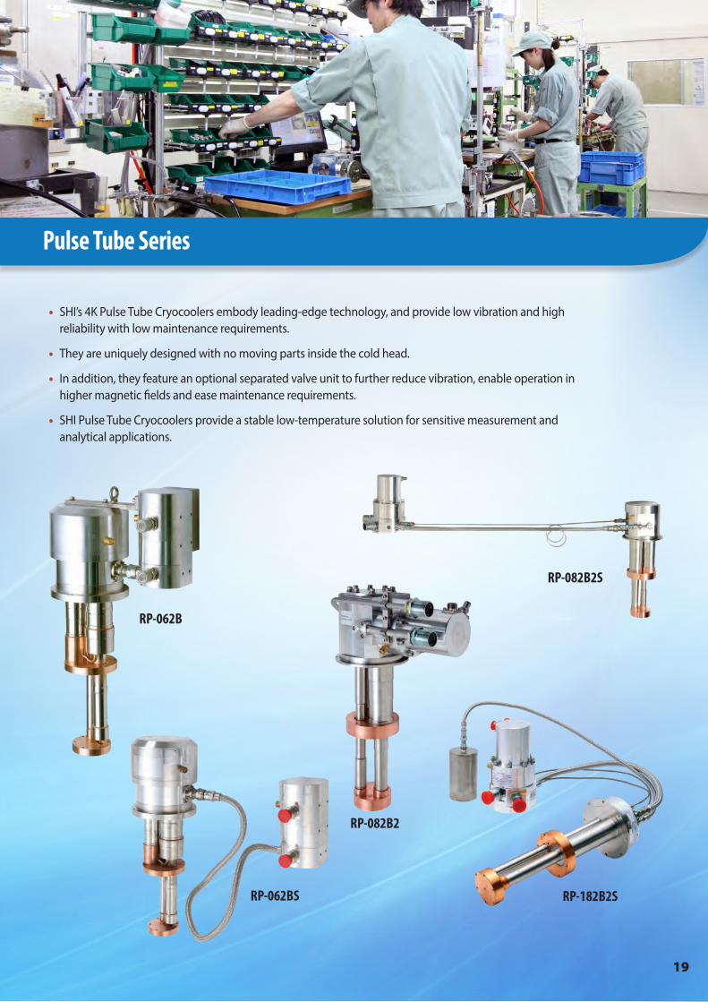
• SHI’s 4K Pulse Tube Cryocoolers embody leading-edge technology, and provide low vibration and high reliability with low maintenance requirements.
• They are uniquely designed with no moving parts inside the cold head.
• In addition, they feature an optional separated valve unit to further reduce vibration, enable operation in higher magnetic fields and ease maintenance requirements.
• SHI Pulse Tube Cryocoolers provide a stable low-temperature solution for sensitive measurement and analytical applications.
RP-062B
RP-062BS
RP-082B2
RP-082B2S
RP-182B2S
20
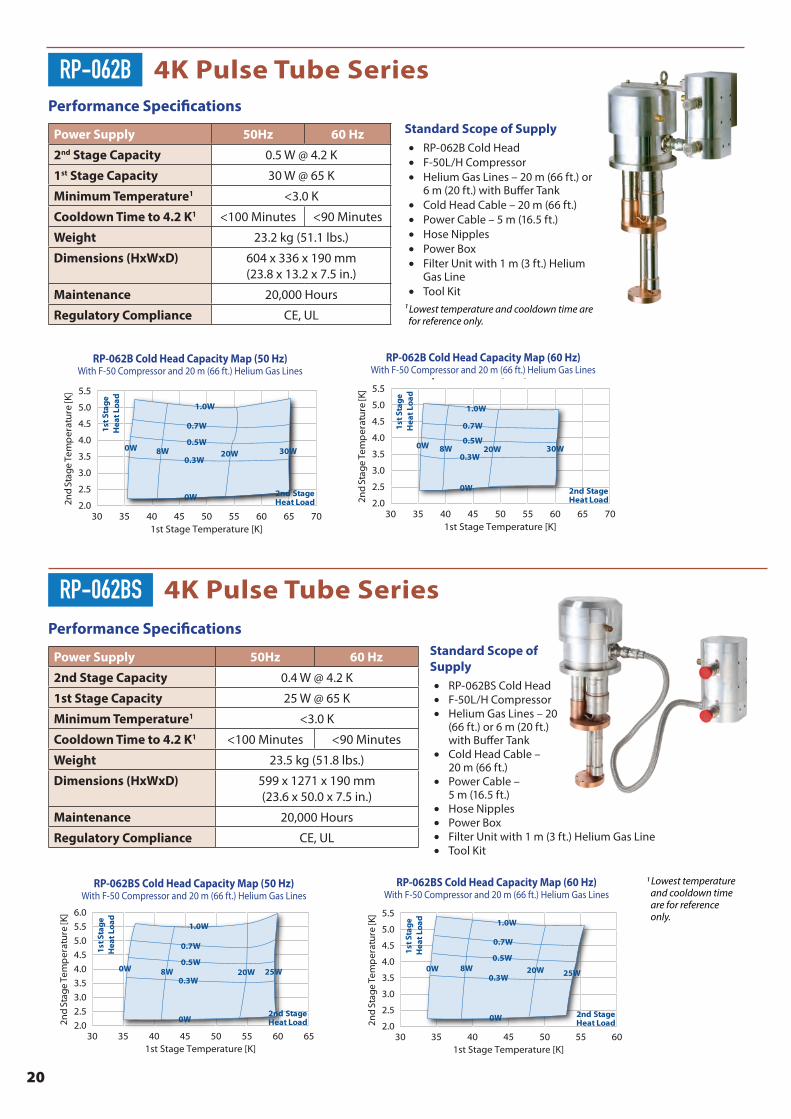
Performance Specifications
Power Supply 50Hz 60 Hz
2nd Stage Capacity 0.5 W @ 4.2 K
1st Stage Capacity 30 W @ 65 K
Minimum Temperature1 <3.0 K
Cooldown Time to 4.2 K1 <100 Minutes <90 Minutes
Weight 23.2 kg (51.1 lbs.)
Dimensions (HxWxD) 604 x 336 x 190 mm(23.8 x 13.2 x 7.5 in.)
Maintenance 20,000 Hours
Regulatory Compliance CE, UL
Standard Scope of Supply• RP-062B Cold Head• F-50L/H Compressor• Helium Gas Lines – 20 m (66 ft.) or
6 m (20 ft.) with Buffer Tank• Cold Head Cable – 20 m (66 ft.)• Power Cable – 5 m (16.5 ft.)• Hose Nipples• Power Box• Filter Unit with 1 m (3 ft.) Helium
Gas Line• Tool Kit
¹ Lowest temperature and cooldown time are for reference only.
RP-062B 4K Pulse Tube Series
30 35 50 55 6040 45 70652.0
2.5
3.0
3.5
4.0
4.5
5.0
5.5
2nd
Sta
ge T
emp
erat
ure
[K]
1st Stage Temperature [K]
1st S
tag
e H
eat
Load
2nd Stage Heat Load
0W
0W
0.3W
0.5W
0.7W
1.0W
30W20W8W
SRP-062B Cold Head Capacity Map (50 Hz)With F-50 Compressor and 20 m (66 ft.) Helium Gas Lines
RP-062B Cold Head Capacity Map (50 Hz)With F-50 Compressor and 20 m (66 ft.) Helium Gas Lines
30 35 50 55 6040 45 70652.0
2.5
3.0
3.5
4.0
4.5
5.0
5.5
2nd
Sta
ge T
emp
erat
ure
[K]
1st Stage Temperature [K]
1st S
tag
e H
eat
Load
2nd Stage Heat Load
0W
0W
0.3W
0.5W
0.7W
1.0W
30W20W8W
SRP-062B Cold Head Capacity Map (60 Hz)With F-50 Compressor and 20 m (66 ft.) Helium Gas Lines
RP-062B Cold Head Capacity Map (60 Hz)With F-50 Compressor and 20 m (66 ft.) Helium Gas Lines
Performance Specifications
Power Supply 50Hz 60 Hz
2nd Stage Capacity 0.4 W @ 4.2 K
1st Stage Capacity 25 W @ 65 K
Minimum Temperature1 <3.0 K
Cooldown Time to 4.2 K1 <100 Minutes <90 Minutes
Weight 23.5 kg (51.8 lbs.)
Dimensions (HxWxD) 599 x 1271 x 190 mm (23.6 x 50.0 x 7.5 in.)
Maintenance 20,000 Hours
Regulatory Compliance CE, UL
Standard Scope of Supply• RP-062BS Cold Head• F-50L/H Compressor• Helium Gas Lines – 20
(66 ft.) or 6 m (20 ft.) with Buffer Tank
• Cold Head Cable – 20 m (66 ft.)
• Power Cable – 5 m (16.5 ft.)
• Hose Nipples• Power Box• Filter Unit with 1 m (3 ft.) Helium Gas Line• Tool Kit
RP-062BS 4K Pulse Tube Series
RP-062BS Cold Head Capacity Map (50 Hz)With F-50 Compressor and 20 m (66 ft.) Helium Gas Lines
RP-062BS Cold Head Capacity Map (60 Hz)With F-50 Compressor and 20 m (66 ft.) Helium Gas Lines
30 35 50 55 6040 45 652.0
2.5
3.0
3.5
4.0
4.5
5.0
6.0
5.5
2nd
Sta
ge T
emp
erat
ure
[K]
1st Stage Temperature [K]
1st S
tag
e H
eat
Load
2nd Stage Heat Load
0W
0W
0.3W
0.5W
0.7W
1.0W
25W20W8W
SRP-062BS Cold Head Capacity Map (50 Hz)With F-50 Compressor and 20 m (66 ft.) Helium Gas Lines
30 35 50 5540 45 602.0
2.5
3.0
3.5
4.0
4.5
5.0
5.5
2nd
Sta
ge T
emp
erat
ure
[K]
1st Stage Temperature [K]
1st S
tag
e H
eat
Load
2nd Stage Heat Load
0W
0W
0.3W
0.5W
0.7W
1.0W
25W20W8W
SRP-062BS Cold Head Capacity Map (60 Hz)With F-50 Compressor and 20 m (66 ft.) Helium Gas Lines
1 Lowest temperature and cooldown time are for reference only.
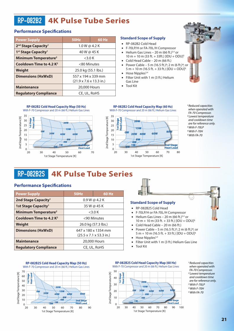
21
Performance Specifications
Power Supply 50Hz 60 Hz
2nd Stage Capacity1 0.9 W @ 4.2 K
1st Stage Capacity1 35 W @ 45 K
Minimum Temperature2 <3.0 K
Cooldown Time to 4.2 K2 <90 Minutes
Weight 26.0 kg (57.3 lbs.)
Dimensions (HxWxD) 647 x 180 x 1354 mm (25.5 x 7.1 x 53.3 in.)
Maintenance 20,000 Hours
Regulatory Compliance CE, UL, RoHS
Standard Scope of Supply• RP-082B2S Cold Head• F-70LP/H or FA-70L/H Compressor• Helium Gas Lines – 20 m (66 ft.)3,4 or
10 m + 10 m (33 ft. + 33 ft.) [IDU + ODU]5• Cold Head Cable – 20 m (66 ft.)• Power Cable – 5 m (16.5 ft.)3; 2 m (6 ft.)4; or
5 m + 10 m (16.5 ft. + 33 ft.) [IDU + ODU]5• Hose Nipples3,4
• Filter Unit with 1 m (3 ft.) Helium Gas Line• Tool Kit
RP-082B2S 4K Pulse Tube Series
0
10
20
50
40
30
60
70
2nd
Sta
ge T
emp
erat
ure
[K]
20 40 5030 908060 701st Stage Temperature [K]
1st
Sta
ge
Hea
t Lo
ad
2nd Stage Heat Load
0W
0W 1W4W
8W
15W
20W
40W20W 80W60W
SRP-082B2S Cold Head Capacity Map (50 Hz)With F-70 Compressor and 20 m (66 ft.) Helium Gas Lines
0
10
20
30
40
50
2nd
Sta
ge T
emp
erat
ure
[K]
20 5040 6030 1009080701st Stage Temperature [K]
1st
Sta
ge
Hea
t Lo
ad
2nd Stage Heat Load
0W
0W1W
4W
8W
15W
20W
40W20W 80W60W
SRP-082B2S Cold Head Capacity Map (60 Hz)With F-70 Compressor and 20 m (66 ft.) Helium Gas Lines
RP-082B2S Cold Head Capacity Map (50 Hz)With F-70 Compressor and 20 m (66 ft.) Helium Gas Lines
RP-082B2S Cold Head Capacity Map (60 Hz)With F-70 Compressor and 20 m (66 ft.) Helium Gas Lines
Performance Specifications
Power Supply 50Hz 60 Hz
2nd Stage Capacity1 1.0 W @ 4.2 K
1st Stage Capacity1 40 W @ 45 K
Minimum Temperature2 <3.0 K
Cooldown Time to 4.2 K2 <80 Minutes
Weight 25.0 kg (55.1 lbs.)
Dimensions (HxWxD) 557 x 194 x 339 mm(21.9 x 7.6 x 13.3 in.)
Maintenance 20,000 Hours
Regulatory Compliance CE, UL, RoHS
Standard Scope of Supply• RP-082B2 Cold Head• F-70LP/H or FA-70L/H Compressor• Helium Gas Lines – 20 m (66 ft.)3,4 or
10 m + 10 m (33 ft. + 33ft.) [IDU + ODU]5
• Cold Head Cable – 20 m (66 ft.)• Power Cable – 5 m (16.5 ft.)3; 2 m (6 ft.)4; or
5 m + 10 m (16.5 ft. + 33 ft.) [IDU + ODU]5• Hose Nipples3,4
• Filter Unit with 1 m (3 ft.) Helium Gas Line
• Tool Kit
RP-082B2 4K Pulse Tube Series
SRP-082B2 Cold Head Capacity Map (50 Hz)
0
5
10
15
30
25
20
35
2nd
Sta
ge T
emp
erat
ure
[K]
20 4030 7060501st Stage Temperature [K]
1st
Sta
ge
Hea
t Lo
ad
2nd Stage Heat Load
0W
0W1W
4W8W
15W
20W
40W20W80W
60W
With F-70 Compressor and 20 m (66 ft.) Helium Gas Lines
RP-082B2 Cold Head Capacity Map (50 Hz)With F-70 Compressor and 20 m (66 ft.) Helium Gas Lines
0
5
10
15
20
25
30
35
2nd
Sta
ge T
emp
erat
ure
[K]
20 40 5030 8060 701st Stage Temperature [K]
1st
Sta
ge
Hea
t Lo
ad
2nd Stage Heat Load
0W
0W1W4W
8W
15W
20W
40W 60W80W
20W
SRP-082B2 Cold Head Capacity Map (60 Hz)With F-70 Compressor and 20 m (66 ft.) Helium Gas Lines
RP-082B2 Cold Head Capacity Map (60 Hz)With F-70 Compressor and 20 m (66 ft.) Helium Gas Lines
1 Reduced capacities when operated with FA-70 Compressor. 2 Lowest temperature and cooldown time are for reference only. 3 With F-70LP4 With F-70H5 With FA-70
1 Reduced capacities when operated with FA-70 Compressor. 2 Lowest temperature and cooldown time are for reference only. 3 With F-70LP4 With F-70H5 With FA-70

22
Performance Specifications
Power Supply 50Hz 60 Hz
2nd Stage Capacity 1.5 W @ 4.2 K
1st Stage Capacity 36 W @ 48 K
Minimum Temperature1 <2.8 K
Cooldown Time to 4.2 K1 <60 Minutes
Weight 28.0 kg (61.7 lbs.)
Dimensions (HxD) 539 x ø187 mm(21.2 x ø7.4 in.)
Maintenance 20,000 Hours
Regulatory Compliance CE, UL/cUL, RoHS
Standard Scope of Supply• RP-182B2S Cold Head• F-100L/H Compressor• Helium Gas Lines – 20 m (66 ft.)• Cold Head Cable – 20 m (66 ft.)• Power Cable – 20 m (66 ft.)• Hose Nipples• Tool Kit
¹ Lowest temperature and cooldown time are for reference only.
IMPORTANT: The SRP-182B2S-F100L cannot be installed in Japan, due to Japanese high pressure gas laws. For details, please contact SHI. Please follow all local laws related to high pressure gas regulation.
RP-182B2S 4K Pulse Tube Series
0
5
10
15
25
20
2nd
Sta
ge T
emp
erat
ure
[K]
35 4030 95555045 65 7060 8580 90751st Stage Temperature [K]
2n
d S
tag
e H
eat
Load
1st Stage Heat Load
0W
0W
15W
8W
4W1.5W
20W 80W60W36W
20W
SRP-182B2S Cold Head Capacity Map (50 Hz)With F-100 Compressor and 20 m (66 ft.) Helium Gas Lines
RP-182B2S Cold Head Capacity Map (50 Hz)With F-100 Compressor and 20 m (66 ft.) Helium Gas Lines
0
5
10
15
25
20
2nd
Sta
ge T
emp
erat
ure
[K]
4030 9050 7060 801st Stage Temperature [K]
2n
d S
tag
e H
eat
Load
1st Stage Heat Load
0W
0W
15W
8W
4W1.5W
20W 80W60W36W
20W
SRP-182B2S Cold Head Capacity Map (60 Hz)With F-100 Compressor and 20 m (66 ft.) Helium Gas Lines
RP-182B2S Cold Head Capacity Map (60 Hz)With F-100 Compressor and 20 m (66 ft.) Helium Gas Lines
SHI Cryogenics Group LocationsUnited States
Santa Clara, California
San Diego, California
Elk Grove Village, Illinois
Austin, Texas
Allentown, Pennsylvania
SHI Cryogenics Group LocationsUnited States
23
Specialty Cryocoolers
• In addition to our standard 4K, 10K and Pulse Tube Cryocoolers, SHI Cryogenics Group offers several cryocooler models designed for specialty research applications.
• These models cover a wide range of options, and include a 6.5K Gifford-McMahon Cryocooler as well as several single-stage Cryocoolers.
• Like other Cryocooler products, all Specialty Cryocoolers are backed by SHI’s worldwide sales, service and support network.
CH-204-N
CH-110
CH-210-N
RDK-400B
CH-104
RD-125D
RDK-500BCH-210LCH-110LT
24
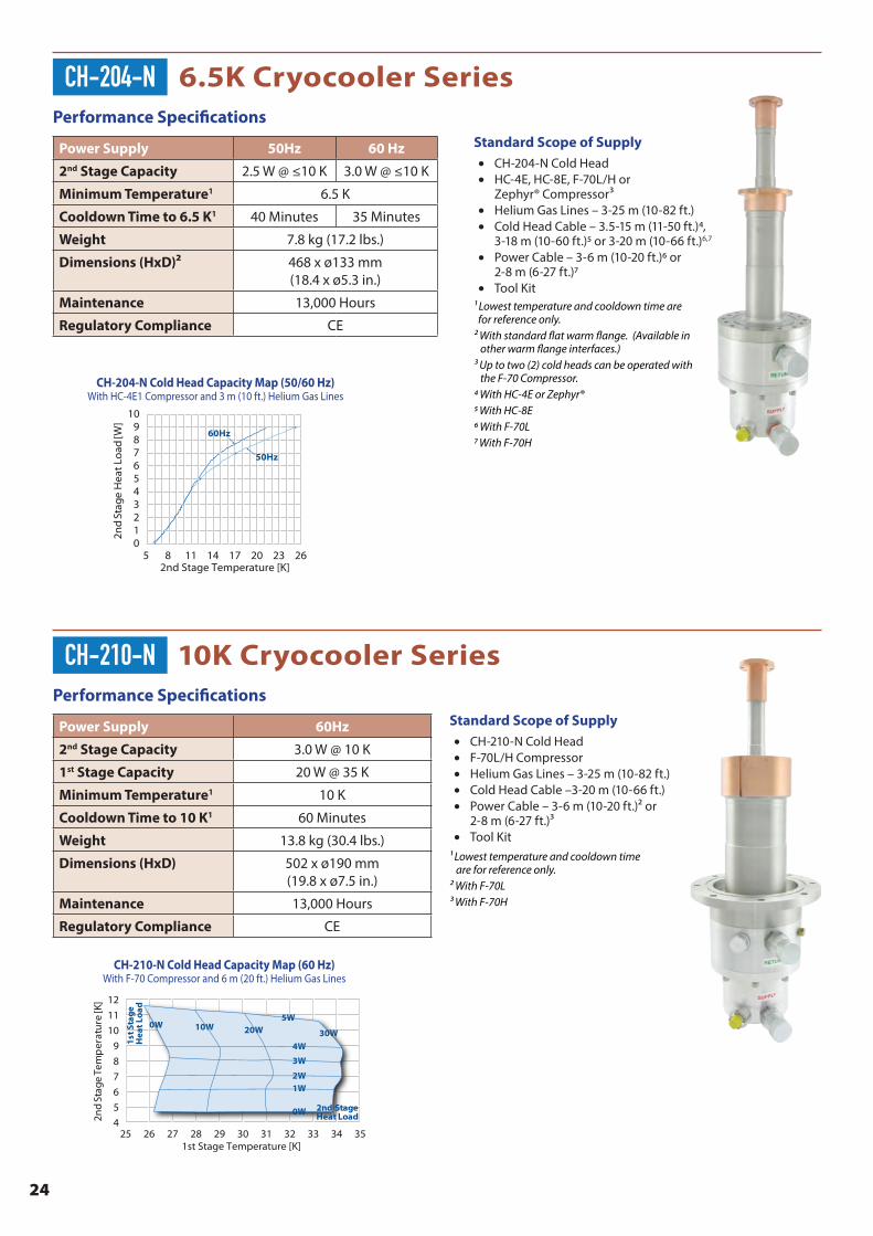
Performance Specifications
Power Supply 50Hz 60 Hz
2nd Stage Capacity 2.5 W @ ≤10 K 3.0 W @ ≤10 K
Minimum Temperature1 6.5 K
Cooldown Time to 6.5 K1 40 Minutes 35 Minutes
Weight 7.8 kg (17.2 lbs.)
Dimensions (HxD)2 468 x ø133 mm(18.4 x ø5.3 in.)
Maintenance 13,000 Hours
Regulatory Compliance CE
Standard Scope of Supply• CH-204-N Cold Head• HC-4E, HC-8E, F-70L/H or
Zephyr® Compressor3• Helium Gas Lines – 3-25 m (10-82 ft.)• Cold Head Cable – 3.5-15 m (11-50 ft.)4,
3-18 m (10-60 ft.)5 or 3-20 m (10-66 ft.)6,7
• Power Cable – 3-6 m (10-20 ft.)6 or 2-8 m (6-27 ft.)7
• Tool Kit1 Lowest temperature and cooldown time are for reference only. 2 With standard flat warm flange. (Available in other warm flange interfaces.)3 Up to two (2) cold heads can be operated with the F-70 Compressor.4 With HC-4E or Zephyr®5 With HC-8E6 With F-70L7 With F-70H
CH-204-N 6.5K Cryocooler Series
0 123456789
10
2nd
Sta
ge H
eat L
oad
[W]
5 8 11 14 17 20 23 262nd Stage Temperature [K]
50Hz
60Hz
CH-204-N Cold Head Capacity Map (50/60 Hz)With HC-4E1 Compressor and 3 m (10 ft.) Helium Gas Lines
CH-204-N Cold Head Capacity Map (50/60 Hz)With HC-4E1 Compressor and 3 m (10 ft.) Helium Gas Lines
Performance Specifications
Power Supply 60Hz
2nd Stage Capacity 3.0 W @ 10 K
1st Stage Capacity 20 W @ 35 K
Minimum Temperature1 10 K
Cooldown Time to 10 K1 60 Minutes
Weight 13.8 kg (30.4 lbs.)
Dimensions (HxD) 502 x ø190 mm (19.8 x ø7.5 in.)
Maintenance 13,000 Hours
Regulatory Compliance CE
Standard Scope of Supply• CH-210-N Cold Head• F-70L/H Compressor• Helium Gas Lines – 3-25 m (10-82 ft.)• Cold Head Cable –3-20 m (10-66 ft.)• Power Cable – 3-6 m (10-20 ft.)2 or
2-8 m (6-27 ft.)3• Tool Kit
1 Lowest temperature and cooldown time are for reference only. 2 With F-70L3 With F-70H
CH-210-N 10K Cryocooler Series
CH-210-N Cold Head Capacity Map (60 Hz)
4
5
6
7
8
9
10
11
12
2nd
Sta
ge T
emp
erat
ure
[K]
25 27 2826 29 30 3231 33 34 351st Stage Temperature [K]
1st S
tag
e H
eat
Load
2nd Stage Heat Load
2W1W
0W
20W
3W
0W 10W
4W
5W
30W
With F-70 Compressor and 6 m (20 ft.) Helium Gas Lines
CH-210-N Cold Head Capacity Map (60 Hz)With F-70 Compressor and 6 m (20 ft.) Helium Gas Lines

25
Performance Specifications
Power Supply 50Hz 60 Hz
2nd Stage Capacity 9.5 W @ 20 K 11 W @ 20 K
1st Stage Capacity 75 W @ 60 K 90 W @ 60 K
Minimum Temperature1 10 K
Cooldown Time to 20 K1 <60 Minutes
Weight 12.1 kg (26.7 lbs.)
Dimensions (HxD) 502 x ø190 mm (19.8 x ø7.5 in.)
Maintenance 13,000 Hours
Regulatory Compliance CE
Standard Scope of Supply• CH-210L Cold Head• F-70L/H Compressor• Helium Gas Lines – 3-25 m (10-82 ft.)• Cold Head Cable –3-20 m (10-66 ft.)• Power Cable – 3-6 m (10-20 ft.)2 or
2-8 m (6-27 ft.)3• Tool Kit
1 Lowest temperature and cooldown time are for reference only. 2 With F-70L3 With F-70H
CH-210L 10K Cryocooler Series
16
18
20
22
24
2nd
Sta
ge T
emp
erat
ure
[K]
50 52 54 56 58 601st Stage Temperature [K]
1st S
tag
e H
eat
Load
2nd Stage Heat Load
10W
80W 9W
70W
9.5W
90W
CH-210L Cold Head Capacity Map (50 Hz)With F-70 Compressor and 20 m (66 ft.) Helium Gas Lines
CH-210L Cold Head Capacity Map (50 Hz)With F-70 Compressor and 20 m (66 ft.) Helium Gas Lines
12
13
14
15
16
17
2nd
Sta
ge T
emp
erat
ure
[K]
53 55 57 59 61 6563 67 691st Stage Temperature [K]
1st S
tag
e H
eat
Load
2nd Stage Heat Load
8W
80W
5W70W
9.5W
90W
CH-210L Cold Head Capacity Map (60 Hz)With F-70 Compressor and 20 m (66 ft.) Helium Gas Lines
CH-210L Cold Head Capacity Map (60 Hz)With F-70 Compressor and 20 m (66 ft.) Helium Gas Lines
Performance Specifications
Power Supply 50Hz 60 Hz
1st Stage Capacity 54 W @ 40 K 70 W @ 40 K
Minimum Temperature2 <25 K
Cooldown Time to 4.2 K2 <30 Minutes
Weight 16.0 kg (35.3 lbs.)
Dimensions (HxWxD) 357 x 180 x 294 mm(14.1 x 7.1 x 11.6 in.)
Maintenance 10,000 Hours
Regulatory Compliance CE, UL
Standard Scope of Supply• RDK-400B Cold Head• F-50L/H, CSA-71A or FA-70L/H
Compressor• Helium Gas Lines – 20 m (66 ft.)2,3;
6 m (20 ft.) with Buffer Tank2,3; or 10 m (33 ft.) [IDU] + 10 m (33 ft.) [ODU]4
• Cold Head Cable –6-20 m (20-66 ft.)2,3 or 10 m (33 ft.)4
• Power Cable – 5 m (16.5 ft.)2,3 or 5 m (16.5 ft.) [IDU] + 10 m (33 ft.) [ODU]4
• Hose Nipples2• Tool Kit
1 Lowest temperature and cooldown time are for reference only. ² With F-503 With CSA-71A4 With FA-70
RDK-400B 40K Cryocooler Series
80
120
160
40
240
200
00 40 6020 80 100 120
50Hz
60Hz
Hea
t Lo
ad [W
]
Temperature [K]
SRDK-400B Cold Head Capacity Map (50/60 Hz)With F-50 Compressor and 20 m (66 ft.) Helium Gas Lines
RDK-400B Cold Head Capacity Map (50/60 Hz)With F-50 Compressor and 20 m (66 ft.) Helium Gas Lines
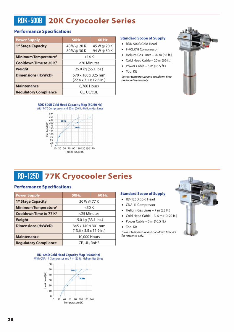
26
Performance Specifications
Power Supply 50Hz 60 Hz
1st Stage Capacity 40 W @ 20 K 80 W @ 30 K
45 W @ 20 K 94 W @ 30 K
Minimum Temperature1 <14 K
Cooldown Time to 20 K1 <70 Minutes
Weight 25.0 kg (55.1 lbs.)
Dimensions (HxWxD) 570 x 180 x 325 mm(22.4 x 7.1 x 12.8 in.)
Maintenance 8,760 Hours
Regulatory Compliance CE, UL/cUL
Standard Scope of Supply• RDK-500B Cold Head
• F-70LP/H Compressor
• Helium Gas Lines – 20 m (66 ft.)
• Cold Head Cable – 20 m (66 ft.)
• Power Cable – 5 m (16.5 ft.)
• Tool Kit¹ Lowest temperature and cooldown time are for reference only.
RDK-500B 20K Cryocooler Series
100 125 150 175 200
50 75
25
275
225250
010 70 90 11030 50 130 150 170
50Hz
60Hz
Hea
t Lo
ad [W
]
Temperature [K]
SRDK-500B Cold Head Capacity Map (50/60 Hz)With F-70 Compressor and 20 m (66 ft.) Helium Gas Lines
RDK-500B Cold Head Capacity Map (50/60 Hz)With F-70 Compressor and 20 m (66 ft.) Helium Gas Lines
Performance Specifications
Power Supply 50Hz 60 Hz
1st Stage Capacity 30 W @ 77 K
Minimum Temperature1 <30 K
Cooldown Time to 77 K1 <25 Minutes
Weight 15.0 kg (33.1 lbs.)
Dimensions (HxWxD) 345 x 140 x 301 mm(13.6 x 5.5 x 11.9 in.)
Maintenance 10,000 Hours
Regulatory Compliance CE, UL, RoHS
Standard Scope of Supply• RD-125D Cold Head
• CNA-11 Compressor
• Helium Gas Lines – 7 m (23 ft.)
• Cold Head Cable – 3-6 m (10-20 ft.)
• Power Cable – 5 m (16.5 ft.)
• Tool Kit¹ Lowest temperature and cooldown time are for reference only.
RD-125D 77K Cryocooler Series
SRD-125D Cold Head Capacity Map (50/60 Hz)With CNA-11 Compressor and 7 m (23 ft.) Helium Gas Lines
10
20
60
50
30
40
00 20 80 100 12040 60 140
Hea
t Lo
ad [W
]
Temperature [K]
50Hz
60Hz
RD-125D Cold Head Capacity Map (50/60 Hz)With CNA-11 Compressor and 7 m (23 ft.) Helium Gas Lines

27
Performance Specifications
Power Supply 50Hz 60 Hz
1st Stage Capacity 34 W @ 77 K 42 W @ 77 K
Minimum Temperature1 ≤40 K
Cooldown Time to 77 K1 <40 Minutes <30 Minutes
Weight 7.9 kg (17.5 lbs.)
Dimensions (HxD)2 362 x ø133 mm(14.3 x ø5.3 in.)
Maintenance 13,000 Hours
Regulatory Compliance CE
Standard Scope of Supply• CH-104 Cold Head• HC-4E, HC-8E, F-70L/H or Zephyr®
Compressor3• Helium Gas Lines – 3-25 m (10-82 ft.)• Cold Head Cable – 3.5-15 m (11-50 ft.)4,
3-18 m (10-60 ft.)5 or 3-20 m (10-66 ft.)6,7
• Power Cable – 3-6 m (10-20 ft.)6 or 2-8 m (6-27 ft.)7
• Tool Kit
1 Lowest temperature and cooldown time are for reference only. 2 With standard flat warm flange. (Available in other warm flange interfaces.)3 Up to two (2) cold heads can be operated with the F-70 Compressor.4 With HC-4E or Zephyr®5 With HC-8E6 With F-70L7 With F-70H
CH-104 77K Cryocooler Series
20 30 40 50 60
10
90
7080
020 100 140 18060 220 260 300
Hea
t Lo
ad [W
]
Temperature [K]
50Hz
60Hz
CH-104 Cold Head Capacity Map (50/60 Hz)With HC-4E1 Compressor and 3 m (10 ft.) Helium Gas Lines
CH-104 Cold Head Capacity Map (50/60 Hz)With HC-4E1 Compressor and 3 m (10 ft.) Helium Gas Lines
Performance Specifications
Power Supply 50Hz 60 Hz
1st Stage Capacity 175 W @ 77 K 200 W @ 77 K
Minimum Temperature1 ≤40 K
Cooldown Time to 77 K1 <35 Minutes <30 Minutes
Weight 13.7 kg (30.2 lbs.)
Dimensions (HxD)2 429 x ø184 mm(16.9 x ø7.2 in.)
Maintenance 13,000 Hours
Regulatory Compliance CE
Standard Scope of Supply• CH-110 Cold Head• HC-4E, HC-8E, F-70L/H, Zephyr® or
FA-70L/H Compressor3• Helium Gas Lines – 3-25 m (10-82 ft.)4,5;
3-20 m (10-66 ft.)6,7; or 10 m (33 ft.) [IDU] + 10 m (33 ft.), 20 m (66 ft.) or 30 m (99 ft.) [ODU]8
• Cold Head Cable – 3.5-15 m (11-50 ft.)4, 3-18 m (10-60 ft.)5, 3-20 m (10-66 ft.)6,7 or 33 ft. (10 m)8
• Power Cable – 3-6 m (10-20 ft.)6; 2-8 m (6-27 ft.)7; or 5 m (16.5 ft.) [IDU] + 10 m (33 ft.), 20 m (66 ft.) or 30 m (99 ft.) [ODU]8
• Tool Kit
1 Lowest temperature and cooldown time are for reference only. 2 With standard flat warm flange. (Available in other warm flange interfaces.)3 Reduced capacities when operated with HC-4E, HC-8E or Zephyr Compressors.4 With HC-4E or Zephyr®5 With HC-8E6 With F-70L7 With F-70H8 With FA-70
CH-110 77K Cryocooler Series
50Hz
60Hz
50
100
250
150
200
010 20 50 60 70 80 9030 40 100110120
Hea
t Lo
ad [W
]
Temperature [K]
CH-110 Cold Head Capacity Map (50/60 Hz)With F-70 Compressor and 20 m (66 ft.) Helium Gas Lines
CH-110 Cold Head Capacity Map (50/60 Hz)With F-70 Compressor and 20 m (66 ft.) Helium Gas Lines
28
Performance Specifications
Power Supply 50Hz 60 Hz
1st Stage Capacity 80 W @ 40 K 95 W @ 40 K
Minimum Temperature1 <15 K
Cooldown Time to 77 K1 <35 Minutes <30 Minutes
Weight 13.8 kg (30.5 lbs.)
Dimensions (HxD)2 429 x ø184 mm(16.9 x ø7.2 in.)
Maintenance 13,000 Hours
Regulatory Compliance CE
Standard Scope of Supply• CH-110LT Cold Head• F-70L/H or FA-70L/H Compressor• Helium Gas Lines –3-20 m (10-66 ft.)3,4;
or 10 m (33 ft.) [IDU] + 10 m (33 ft.), 20 m (66 ft.) or 30 m (99 ft.) [ODU]5
• Cold Head Cable – 3-20 m (10-66 ft.)3,4 or 33 ft. (10 m)5
• Power Cable – 3-6 m (10-20 ft.)3; 2-8 m (6-27 ft.)4; or 5 m (16.5 ft.) [IDU] + 10 m (33 ft.), 20 m (66 ft.) or 30 m (99 ft.) [ODU]5
• Tool Kit
1 Lowest temperature and cooldown time are for reference only. 2 With standard flat warm flange. (Available in other warm flange interfaces.)3 With F-70L⁴ With F-70H⁵ With FA-70
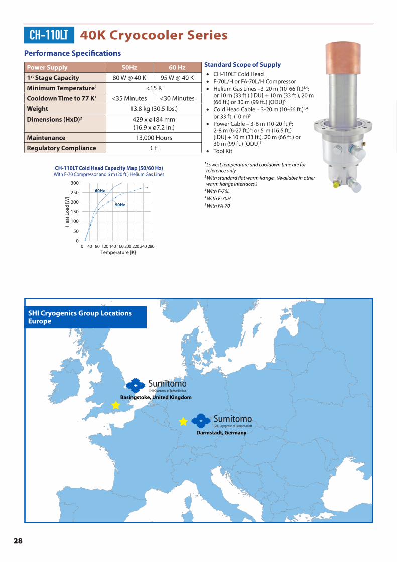
CH-110LT 40K Cryocooler Series
50
100
300
250
150
200
00 40 140 160 200 220 24080 120 280
Hea
t Lo
ad [W
]
Temperature [K]
50Hz
60Hz
CH-110LT Cold Head Capacity Map (50/60 Hz)With F-70 Compressor and 6 m (20 ft.) Helium Gas Lines
CH-110LT Cold Head Capacity Map (50/60 Hz)With F-70 Compressor and 6 m (20 ft.) Helium Gas Lines
SHI Cryogenics Group LocationsEurope
Basingstoke, United Kingdom
Darmstadt, Germany
SHI Cryogenics Group LocationsEurope

29
Custom Cryocooler Designs
In addition to standard configurations, SHI offers a variety of options to customize your cryocooler design. Particular customization options vary by model, but may include:
• Nickel plating
• Bakeable option
• Standard and CF flange options, including bolt-on skirt with ports
• Heat station variations • Flanged or unflanged • Finned recondenser • With or without 1st stage heat station
• Custom cylinder modification
• Helium port orientation
Please contact your local SHI Cryogenics Group office to discuss available options for your next project.
FinnedRecondenser
No 1st Stage Heat
Station
Conflat Flanges
UnflangedHeat
Stations
Nickel Plating
30
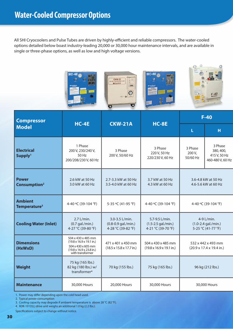
Compressor Model HC-4E CKW-21A HC-8E
F-40 F-50 F-50S F-70 F-100
L H L H L H LP L H L H
Electrical Supply1
1 Phase200 V, 230/240 V,
50 Hz200/208/230 V, 60 Hz
3 Phase200 V, 50/60 Hz
3 Phase220 V, 50 Hz
220/230 V, 60 Hz
3 Phase200 V,
50/60 Hz
3 Phase380, 400,
415 V, 50 Hz460-480 V, 60 Hz
3 Phase200 V,
50/60 Hz
3 Phase380/400/
415 V, 50 Hz
460/480 V, 60 Hz
3 Phase200 V,
50/60 Hz
3 Phase380/400/
415 V, 50 Hz
460/480 V, 60 Hz
3 Phase200 V,
50/60 Hz
3 Phase380-415 V,
50 Hz480 V, 60 Hz
3 Phase200 V, 50 Hz
200, 230 V, 60 Hz
3 Phase 380/400/
415V, 50 Hz 460/480 V,
60 Hz
Power Consumption2
2.6 kW at 50 Hz3.0 kW at 60 Hz
2.7-3.3 kW at 50 Hz3.5-4.0 kW at 60 Hz
3.7 kW at 50 Hz4.3 kW at 60 Hz
3.6-4.8 kW at 50 Hz4.6-5.6 kW at 60 Hz
6.5-7.2 kW at 50 Hz7.5-8.3 kW at 60 Hz
6.5-7.2 kW at 50 Hz7.5-8.3 kW at 60 Hz
6.6-8.5 kW at 50 Hz
7.5-9.8 kW at 60 Hz
6.6-6.9 kW at 50 Hz
7.5-7.8 kW at 60 Hz
6.6-8.5 kW at 50 Hz
7.5-9.8 kW at 60 Hz
11.8-13.7 kW at 50 Hz14.5-16.3 kW at 60 Hz
Ambient Temperature3 4-40 ºC (39-104 °F) 5-35 ºC (41-95 °F) 4-40 ºC (39-104 °F) 4-40 ºC (39-104 °F) 5-35 ºC (41-95 °F) 5-35 ºC (41-95 °F) 4-40 ºC (39-104 °F) 5-35 ºC (41-95 °F)
Cooling Water (Inlet)2.7 L/min.
(0.7 gal./min.)4-27 °C (39-80 °F)
3.0-3.5 L/min. (0.8-0.9 gal./min.)4-28 °C (39-82 °F)
5.7-9.5 L/min. (1.5-2.5 gal./min.)4-21 °C (39-70 °F)
4-9 L/min. (1.0-2.4 gal./min.)5-25 °C (41-77 °F)
7-10 L/min. (1.8-2.6 gal./min.)4-28 °C (39-82 °F)
6-9 L/min. (1.6-2.4 gal./min.)5-25 °C (41-77 °F)
8-10 L/min. (2.1-2.6 gal./min.)4-28 °C (39-82 °F)
Dimensions(HxWxD)
504 x 430 x 485 mm(19.8 x 16.9 x 19.1 in.) 504 x 430 x 605 mm(19.8 x 16.9 x 23.8 in.)
with transformer
471 x 401 x 450 mm(18.5 x 15.8 x 17.7 in.)
504 x 430 x 485 mm(19.8 x 16.9 x 19.1 in.)
532 x 442 x 493 mm(20.9 x 17.4 x 19.4 in.)
591 x 450 x 485 mm(23.3 x 17.7 x 19.1 in.)
671 x 450 x 485 mm (23.3 x 17.7 x 19.1 in.)
532 x 443 x 493 mm(20.9 x 17.4 x 19.4 in.)
1331 x 511 x 512 mm(52.4 x 20.1 x 20.2 in.)
Weight75 kg (165 lbs.)
82 kg (180 lbs.) w/ transformer4
70 kg (155 lbs.) 75 kg (165 lbs.) 96 kg (212 lbs.) 120 kg (264 lbs.) 120 kg (265 lbs.) 100 kg (220 lbs.) 250 kg (551 lbs.)
Maintenance 30,000 Hours 20,000 Hours 30,000 Hours 30,000 Hours 30,000 Hours 30,000 Hours 30,000 Hours 30,000 Hours
All SHI Cryocoolers and Pulse Tubes are driven by highly-efficient and reliable compressors. The water-cooled options detailed below boast industry-leading 20,000 or 30,000 hour maintenance intervals, and are available in single or three-phase options, as well as low and high voltage versions.
1. Power may differ depending upon the cold head used. 2. Typical power consumption 3. Cooling capacity may degrade if ambient temperature is above 28 °C (82 °F). 4. RDK-101D(L) drive unit weighs an additional 1.0 kg (2.2 lbs.).
Specifications subject to change without notice.
Water-Cooled Compressor Options

31
Compressor Model HC-4E CKW-21A HC-8E
F-40 F-50 F-50S F-70 F-100
L H L H L H LP L H L H
Electrical Supply1
1 Phase200 V, 230/240 V,
50 Hz200/208/230 V, 60 Hz
3 Phase200 V, 50/60 Hz
3 Phase220 V, 50 Hz
220/230 V, 60 Hz
3 Phase200 V,
50/60 Hz
3 Phase380, 400,
415 V, 50 Hz460-480 V, 60 Hz
3 Phase200 V,
50/60 Hz
3 Phase380/400/
415 V, 50 Hz
460/480 V, 60 Hz
3 Phase200 V,
50/60 Hz
3 Phase380/400/
415 V, 50 Hz
460/480 V, 60 Hz
3 Phase200 V,
50/60 Hz
3 Phase380-415 V,
50 Hz480 V, 60 Hz
3 Phase200 V, 50 Hz
200, 230 V, 60 Hz
3 Phase 380/400/
415V, 50 Hz 460/480 V,
60 Hz
Power Consumption2
2.6 kW at 50 Hz3.0 kW at 60 Hz
2.7-3.3 kW at 50 Hz3.5-4.0 kW at 60 Hz
3.7 kW at 50 Hz4.3 kW at 60 Hz
3.6-4.8 kW at 50 Hz4.6-5.6 kW at 60 Hz
6.5-7.2 kW at 50 Hz7.5-8.3 kW at 60 Hz
6.5-7.2 kW at 50 Hz7.5-8.3 kW at 60 Hz
6.6-8.5 kW at 50 Hz
7.5-9.8 kW at 60 Hz
6.6-6.9 kW at 50 Hz
7.5-7.8 kW at 60 Hz
6.6-8.5 kW at 50 Hz
7.5-9.8 kW at 60 Hz
11.8-13.7 kW at 50 Hz14.5-16.3 kW at 60 Hz
Ambient Temperature3 4-40 ºC (39-104 °F) 5-35 ºC (41-95 °F) 4-40 ºC (39-104 °F) 4-40 ºC (39-104 °F) 5-35 ºC (41-95 °F) 5-35 ºC (41-95 °F) 4-40 ºC (39-104 °F) 5-35 ºC (41-95 °F)
Cooling Water (Inlet)2.7 L/min.
(0.7 gal./min.)4-27 °C (39-80 °F)
3.0-3.5 L/min. (0.8-0.9 gal./min.)4-28 °C (39-82 °F)
5.7-9.5 L/min. (1.5-2.5 gal./min.)4-21 °C (39-70 °F)
4-9 L/min. (1.0-2.4 gal./min.)5-25 °C (41-77 °F)
7-10 L/min. (1.8-2.6 gal./min.)4-28 °C (39-82 °F)
6-9 L/min. (1.6-2.4 gal./min.)5-25 °C (41-77 °F)
8-10 L/min. (2.1-2.6 gal./min.)4-28 °C (39-82 °F)
Dimensions(HxWxD)
504 x 430 x 485 mm(19.8 x 16.9 x 19.1 in.) 504 x 430 x 605 mm(19.8 x 16.9 x 23.8 in.)
with transformer
471 x 401 x 450 mm(18.5 x 15.8 x 17.7 in.)
504 x 430 x 485 mm(19.8 x 16.9 x 19.1 in.)
532 x 442 x 493 mm(20.9 x 17.4 x 19.4 in.)
591 x 450 x 485 mm(23.3 x 17.7 x 19.1 in.)
671 x 450 x 485 mm (23.3 x 17.7 x 19.1 in.)
532 x 443 x 493 mm(20.9 x 17.4 x 19.4 in.)
1331 x 511 x 512 mm(52.4 x 20.1 x 20.2 in.)
Weight75 kg (165 lbs.)
82 kg (180 lbs.) w/ transformer4
70 kg (155 lbs.) 75 kg (165 lbs.) 96 kg (212 lbs.) 120 kg (264 lbs.) 120 kg (265 lbs.) 100 kg (220 lbs.) 250 kg (551 lbs.)
Maintenance 30,000 Hours 20,000 Hours 30,000 Hours 30,000 Hours 30,000 Hours 30,000 Hours 30,000 Hours 30,000 Hours
7-10 L/min. (1.8-2.6 gal./min.)4-28 °C (39-82 °F)
32
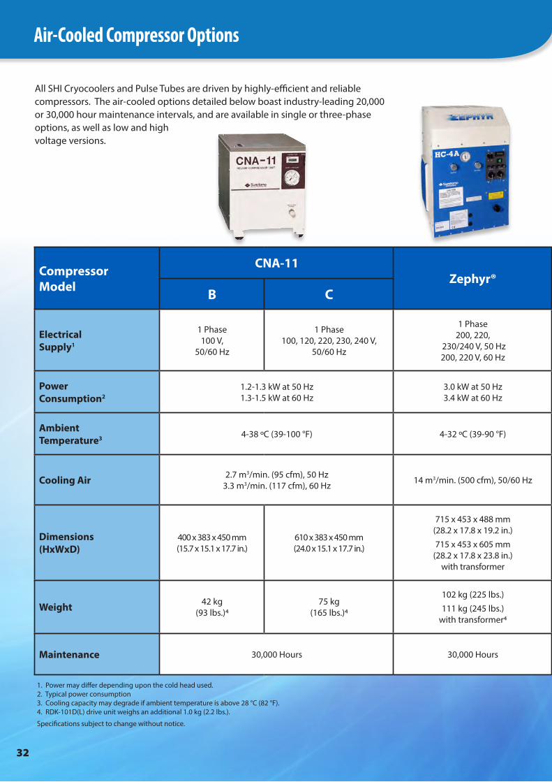
Air-Cooled Compressor Options
Compressor Model
CNA-11Zephyr®
FA-40CSA-71A
FA-70
B C L H L H
Electrical Supply1
1 Phase100 V,
50/60 Hz
1 Phase100, 120, 220, 230, 240 V,
50/60 Hz
1 Phase200, 220,
230/240 V, 50 Hz200, 220 V, 60 Hz
3 Phase200 V,
50/60 Hz
3 Phase380/400/415 V, 50 Hz
460/480 V, 60 Hz
3 Phase200 V, 50/60 Hz
3 Phase200 V, 50/60 Hz
3 Phase380/400/415 V,
50 Hz460/480 V, 60 Hz
Power Consumption2
1.2-1.3 kW at 50 Hz1.3-1.5 kW at 60 Hz
3.0 kW at 50 Hz3.4 kW at 60 Hz
3.6-5.4 kW at 50 Hz4.6-6.4 kW at 60 Hz
6.5-7.2 kW at 50 Hz7.5-8.3 kW at 60 Hz
6.9-8.0 kW at 50 Hz7.9-9.0 kW at 60 Hz
Ambient Temperature3 4-38 ºC (39-100 °F) 4-32 ºC (39-90 °F) 4-38 ºC (39-100 °F) 5-35 ºC (41-95 °F) 4-40 ºC (39-104 °F) - Indoor
¯30-45 ºC (¯22-113 °F) - Outdoor
Cooling Air 2.7 m3/min. (95 cfm), 50 Hz3.3 m3/min. (117 cfm), 60 Hz 14 m3/min. (500 cfm), 50/60 Hz 14.7 m3/min. (520 cfm), 50 Hz
17.6 m3/min. (620 cfm) 60 Hz28 m3/min. (989 cfm),
50/60 Hz
23.5/47.3 m3/min. (830/1670 cfm), 50 Hz26.6/53.8 m3/min. (940/1900 cfm), 60 Hz
Low/high fan speed
Dimensions(HxWxD)
400 x 383 x 450 mm(15.7 x 15.1 x 17.7 in.)
610 x 383 x 450 mm(24.0 x 15.1 x 17.7 in.)
715 x 453 x 488 mm(28.2 x 17.8 x 19.2 in.)715 x 453 x 605 mm
(28.2 x 17.8 x 23.8 in.)with transformer
889 x 442 x 493 mm(35.0 x 17.4 x 19.4 in.)
885 x 550 x 550 mm(34.8 x 21.7 x 21.7 in.)
652 x 267 x 546 mm (25.7 x 10.5 x 21.5 in.) - Indoor
1016 x 391 x 948 mm (40 x 15.4 x 37.3 in.) - Outdoor
Weight 42 kg (93 lbs.)4
75 kg (165 lbs.)4
102 kg (225 lbs.)111 kg (245 lbs.)
with transformer4110 kg (242 lbs.) 140 kg (309 lbs.) 46 kg (101 lbs.) - Indoor
142 kg (312 lbs.) - Outdoor
Maintenance 30,000 Hours 30,000 Hours 30,000 Hours 20,000 Hours 30,000 Hours
All SHI Cryocoolers and Pulse Tubes are driven by highly-efficient and reliable compressors. The air-cooled options detailed below boast industry-leading 20,000 or 30,000 hour maintenance intervals, and are available in single or three-phase options, as well as low and high voltage versions.
1. Power may differ depending upon the cold head used.2. Typical power consumption3. Cooling capacity may degrade if ambient temperature is above 28 °C (82 °F). 4. RDK-101D(L) drive unit weighs an additional 1.0 kg (2.2 lbs.).
Specifications subject to change without notice.
33
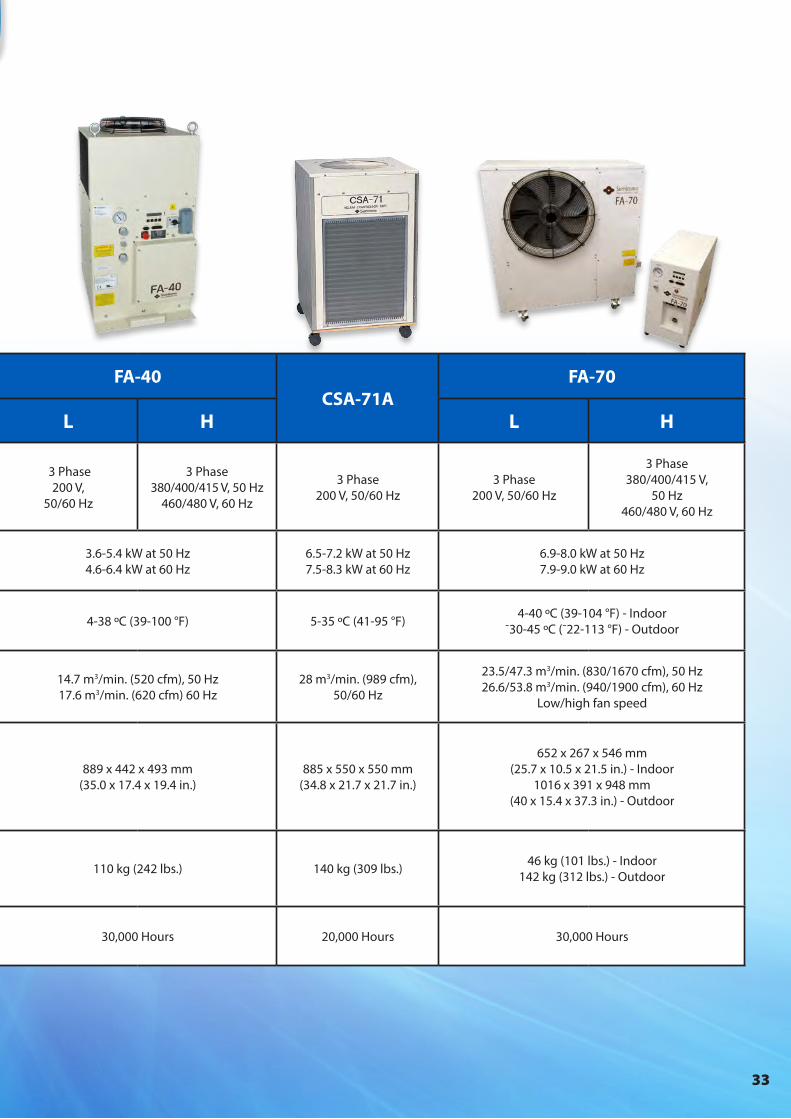
Compressor Model
CNA-11Zephyr®
FA-40CSA-71A
FA-70
B C L H L H
Electrical Supply1
1 Phase100 V,
50/60 Hz
1 Phase100, 120, 220, 230, 240 V,
50/60 Hz
1 Phase200, 220,
230/240 V, 50 Hz200, 220 V, 60 Hz
3 Phase200 V,
50/60 Hz
3 Phase380/400/415 V, 50 Hz
460/480 V, 60 Hz
3 Phase200 V, 50/60 Hz
3 Phase200 V, 50/60 Hz
3 Phase380/400/415 V,
50 Hz460/480 V, 60 Hz
Power Consumption2
1.2-1.3 kW at 50 Hz1.3-1.5 kW at 60 Hz
3.0 kW at 50 Hz3.4 kW at 60 Hz
3.6-5.4 kW at 50 Hz4.6-6.4 kW at 60 Hz
6.5-7.2 kW at 50 Hz7.5-8.3 kW at 60 Hz
6.9-8.0 kW at 50 Hz7.9-9.0 kW at 60 Hz
Ambient Temperature3 4-38 ºC (39-100 °F) 4-32 ºC (39-90 °F) 4-38 ºC (39-100 °F) 5-35 ºC (41-95 °F) 4-40 ºC (39-104 °F) - Indoor
¯30-45 ºC (¯22-113 °F) - Outdoor
Cooling Air 2.7 m3/min. (95 cfm), 50 Hz3.3 m3/min. (117 cfm), 60 Hz 14 m3/min. (500 cfm), 50/60 Hz 14.7 m3/min. (520 cfm), 50 Hz
17.6 m3/min. (620 cfm) 60 Hz28 m3/min. (989 cfm),
50/60 Hz
23.5/47.3 m3/min. (830/1670 cfm), 50 Hz26.6/53.8 m3/min. (940/1900 cfm), 60 Hz
Low/high fan speed
Dimensions(HxWxD)
400 x 383 x 450 mm(15.7 x 15.1 x 17.7 in.)
610 x 383 x 450 mm(24.0 x 15.1 x 17.7 in.)
715 x 453 x 488 mm(28.2 x 17.8 x 19.2 in.)715 x 453 x 605 mm
(28.2 x 17.8 x 23.8 in.)with transformer
889 x 442 x 493 mm(35.0 x 17.4 x 19.4 in.)
885 x 550 x 550 mm(34.8 x 21.7 x 21.7 in.)
652 x 267 x 546 mm (25.7 x 10.5 x 21.5 in.) - Indoor
1016 x 391 x 948 mm (40 x 15.4 x 37.3 in.) - Outdoor
Weight 42 kg (93 lbs.)4
75 kg (165 lbs.)4
102 kg (225 lbs.)111 kg (245 lbs.)
with transformer4110 kg (242 lbs.) 140 kg (309 lbs.) 46 kg (101 lbs.) - Indoor
142 kg (312 lbs.) - Outdoor
Maintenance 30,000 Hours 30,000 Hours 30,000 Hours 20,000 Hours 30,000 Hours

34
Service
Global Service & Support ProgramsAt SHI Cryogenics Group, we realize that our customers are diverse and the markets they serve are demanding and unique. In response, our global service and support network offers responsive and value-added support for our complete range of products. Our factory-trained technicians are located in strategic service centers around the globe and offer 24/7 on-call support.
Our service and support offerings differ by product type. However, our complete range of services is both flexible and cost effective, including:
• Product return to local service depot for service, repair or complete refurbishment
• Assistance in diagnosing equipment issues via phone or e-mail• Product exchange programs (contact your local
service center for available products)SHI factory-trained service technicians are also available for on-site training, scheduled maintenance or emergency visits.
RDK Series Cryocooler Service OptionsProduct repairs and refurbishments performed at SHI Service Centers include:
• Flow check of all internal parts to ensure optimum refrigeration capacity• Replacement of required wear items—seals, valve disc, valve stem, capillaries and displacers, when necessary• Performance testing to factory specification• Leak check, both pressurized and for vacuum integrity, where applicable
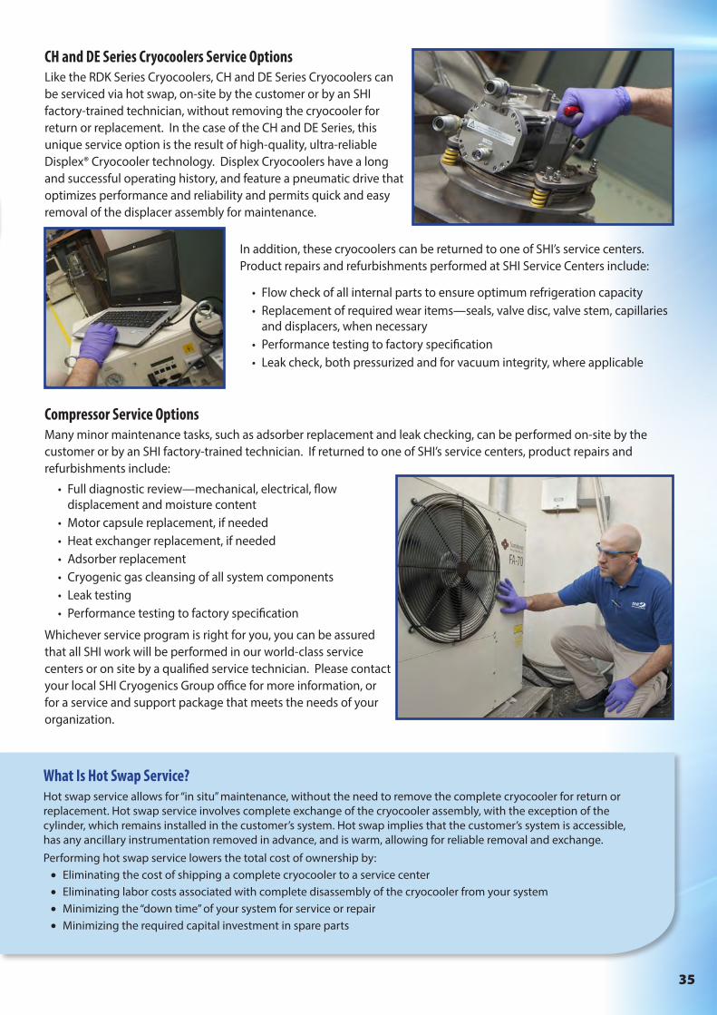
We also understand that there are cases where complete removal and return of the cryocooler is overly difficult. In response, SHI also offers “hot swap” service performed by SHI technicians.
RP Series Pulse Tube Cryocooler Service OptionsDue to the unique operating environment of these cryocoolers, on-site service and maintenance by non-SHI technicians is not recommended at this time. SHI technicians can perform a limited amount of service on-site, including the cleaning and replacement of wear items, gas cleanup and additional tuning. However, the most reliable approach to service and maintenance on these cryocoolers is to return them to one of SHI’s service centers. Product repairs and refurbishments performed at SHI Service Centers include:
• Replacement of required wear items—valve stem and filter unit, when necessary• Cryogenic gas cleansing of all system components • Performance testing to factory specification• Leak check, both pressurized and for vacuum integrity, where applicable
• Customer training programs• Customized service contracts• Full factory warranty
35
CH and DE Series Cryocoolers Service OptionsLike the RDK Series Cryocoolers, CH and DE Series Cryocoolers can be serviced via hot swap, on-site by the customer or by an SHI factory-trained technician, without removing the cryocooler for return or replacement. In the case of the CH and DE Series, this unique service option is the result of high-quality, ultra-reliable Displex® Cryocooler technology. Displex Cryocoolers have a long and successful operating history, and feature a pneumatic drive that optimizes performance and reliability and permits quick and easy removal of the displacer assembly for maintenance.
What Is Hot Swap Service?Hot swap service allows for “in situ” maintenance, without the need to remove the complete cryocooler for return or replacement. Hot swap service involves complete exchange of the cryocooler assembly, with the exception of the cylinder, which remains installed in the customer’s system. Hot swap implies that the customer’s system is accessible, has any ancillary instrumentation removed in advance, and is warm, allowing for reliable removal and exchange.Performing hot swap service lowers the total cost of ownership by:
• Eliminating the cost of shipping a complete cryocooler to a service center• Eliminating labor costs associated with complete disassembly of the cryocooler from your system• Minimizing the “down time” of your system for service or repair• Minimizing the required capital investment in spare parts
In addition, these cryocoolers can be returned to one of SHI’s service centers. Product repairs and refurbishments performed at SHI Service Centers include:
• Flow check of all internal parts to ensure optimum refrigeration capacity• Replacement of required wear items—seals, valve disc, valve stem, capillaries
and displacers, when necessary• Performance testing to factory specification• Leak check, both pressurized and for vacuum integrity, where applicable
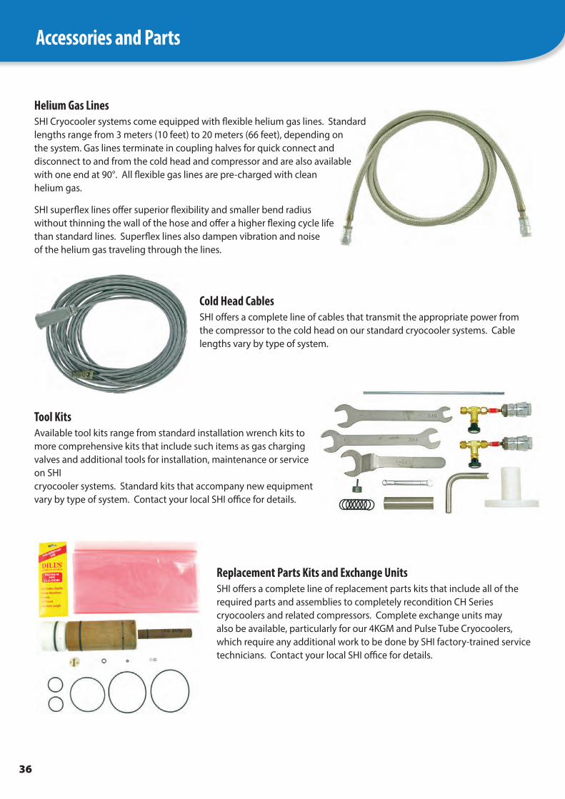
Compressor Service OptionsMany minor maintenance tasks, such as adsorber replacement and leak checking, can be performed on-site by the customer or by an SHI factory-trained technician. If returned to one of SHI’s service centers, product repairs and refurbishments include:
• Full diagnostic review—mechanical, electrical, flow displacement and moisture content
• Motor capsule replacement, if needed• Heat exchanger replacement, if needed• Adsorber replacement• Cryogenic gas cleansing of all system components• Leak testing• Performance testing to factory specification
Whichever service program is right for you, you can be assured that all SHI work will be performed in our world-class service centers or on site by a qualified service technician. Please contact your local SHI Cryogenics Group office for more information, or for a service and support package that meets the needs of your organization.
36
Accessories and Parts
Helium Gas LinesSHI Cryocooler systems come equipped with flexible helium gas lines. Standard lengths range from 3 meters (10 feet) to 20 meters (66 feet), depending on the system. Gas lines terminate in coupling halves for quick connect and disconnect to and from the cold head and compressor and are also available with one end at 90°. All flexible gas lines are pre-charged with clean helium gas.
SHI superflex lines offer superior flexibility and smaller bend radius without thinning the wall of the hose and offer a higher flexing cycle life than standard lines. Superflex lines also dampen vibration and noise of the helium gas traveling through the lines.
Cold Head CablesSHI offers a complete line of cables that transmit the appropriate power from the compressor to the cold head on our standard cryocooler systems. Cable lengths vary by type of system.
Tool KitsAvailable tool kits range from standard installation wrench kits to more comprehensive kits that include such items as gas charging valves and additional tools for installation, maintenance or service on SHI cryocooler systems. Standard kits that accompany new equipment vary by type of system. Contact your local SHI office for details.
Replacement Parts Kits and Exchange UnitsSHI offers a complete line of replacement parts kits that include all of the required parts and assemblies to completely recondition CH Series cryocoolers and related compressors. Complete exchange units may also be available, particularly for our 4KGM and Pulse Tube Cryocoolers, which require any additional work to be done by SHI factory-trained service technicians. Contact your local SHI office for details.

37
In addition to the cryocoolers featured in this catalogue, SHI Cryogenics Group designs and manufactures Cryopumps, Shield Coolers and other low temperature cooling technology.
SICERA® Ultra CryopumpsThe SICERA Ultra Cryopump uses SHI proprietary inverter technology to reduce customer energy costs, allowing up to eleven 8-inch pumps to operate on a single compressor. The resulting savings and increased production efficiency make SICERA Ultra ideal for high-volume production of semiconductor wafers, flat panel displays and other semiconductor-related products.
The complete SICERA Ultra cryopump system includes a compressor and remote controller, which have been thoroughly tested to withstand the most demanding vacuum applications. Through continuous control of both the cryocooler and compressor, SHI Cryogenics Group is able to offer a reliable cryopump system with significant energy savings, as well as excellent temperature and vacuum stability.
SIGNET® CryopumpsSIGNET Cryopumps use double inverter technology to offer increased energy savings for sputtering and evaporation systems. Available in 12 through 22-inch sizes, SIGNET systems are specially designed for multi-pump operation. Between two and four pumps can operate on a single compressor, reducing the system’s overall footprint, as well as its total operating cost. Like SICERA, the complete SIGNET cryopump system includes a robust compressor and remote controller. Its intelligent design combines a high-efficiency design with power and water savings to create a complete package for the flat panel display and similar industries.
Marathon® CP CryopumpsMarathon CP Series Cryopumps are specifically designed to meet the needs of high vacuum processes. Applications for these versatile systems range from custom laboratory equipment to industrial-scale tools. Manufacturers of semiconductor devices, flat panel displays, test equipment, solar manufacturing and a wide variety of coating and thermal vacuum systems require efficient, reliable and robust systems that offer a low cost of ownership. The Marathon CP Series Cryopumps deliver on all fronts.
A range of standard and low profile enclosures, ANSI, ISO and CF flanges, as well as manual and fully automatic features, ensure that users have modularity and flexibility to choose from when designing their systems. All Marathon CP Series Cryopumps are driven by highly-efficient and reliable helium compressors. These compressors boast an industry leading 30,000 hour maintenance interval. Compressors are available in single-phase and three-phase, low and high voltage versions.
For those users requiring the latest in efficient, fully-automated operation, SHI Cryogenics Group offers our Marathon Cryopump Controller (MCC). The MCC enables fully automatic operation and monitoring of the cryopump system using commands from a host computer and industry standard cryopump protocol. If you do not utilize a host computer, optional software is available to interface the MCC to a standard Windows-based computer. The result of utilizing the Marathon CP Cryopump with MCC is greatly reduced downtime between production cycles, improved process times and better overall efficiency of the user’s process.
Marathon® CP Cryopumps
SIGNET® Cryopumps
SICERA® Ultra Cryopumps
Other Products
38
Notes

39

For Information in:Asia
Sumitomo Heavy Industries, Ltd.ThinkPark Tower1-1 Osaki 2-chome, Shinagawa-kuTokyo 141-6025JapanPhone: +81-3-6737-2550 Fax: +81-3-6866-5114E-mail: [email protected]
Service Office2-1-1, Yato-cho, Nishitokyo-city Tokyo 188-8585 JapanPhone: +81-42-468-4252 Fax: +81-42-468-4254
Sumitomo (SHI) Cryogenics Shanghai, Ltd. Building 15, Lane 333 Zhujian Road, Minhang District Shanghai 201107 P.R. ChinaPhone: +86-21-5486-6318 Fax: +86;21;5486-0067E-mail: [email protected] [email protected]
Sumitomo (SHI) Cryogenics Korea, Co., Ltd.280-3, Saneop-ro 155beon-gil, Gweonseon-Gu Suwon-Si, Gyeonggi-DoSuwon-City , 441-813 South KoreaPhone: +82-31-278-3050 Fax: + 82-31-278-3053E-mail: [email protected] [email protected]
Sumitomo (SHI) Cryogenics Taiwan Co., Ltd.4th Floor, No.3 Lane 216, Gongyuan RoadHsinchu City 30069Taiwan R.O.CPhone: +886-3-561-2557 Fax: +886-3-562-3400
United States
Sumitomo (SHI) Cryogenics of America, Inc.1833 Vultee StreetAllentown, PA 18103Phone: +1-610-791-6700 Fax: +1-610-791-0440 E-mail: [email protected] [email protected]
Sumitomo (SHI) Cryogenics of America, Inc.1500-C Higgins Road Elk Grove Village, IL 60007Phone: +1-847-290-5801 Fax: +1-847-290-1984
Europe
Sumitomo (SHI) Cryogenics of Europe, Ltd.3 Hamilton Close, Houndmills Industrial Estate Basingstoke, Hampshire RG21 6YT United KingdomPhone: +44-1256-853333 Fax: +44-1256-471507E-mail: [email protected] [email protected]
Sumitomo (SHI) Cryogenics of Europe, GmbHDaimlerweg 5a Darmstadt D-64293 GermanyPhone: +49-6151-860610 Fax: +49-6151-800252E-mail: [email protected]
Visit us anytime, worldwide. www.shicryogenics.com
© SHI Cryogenics Group 6/20