dl.btc.pldl.btc.pl/kamami_wa/hk_54299_7.pdf · warning mutlicopters are not toys. always make...
TRANSCRIPT
KK2.1&KK2.1.5
InstructionManual V1.16S1 Pro Issue 1
This document details the settings available in the KK2.1.X V1.16S1Pro firmware by Steveis.
Special thanks to Rolf Bakke. Without his work, none of this would be possible.

Warning
Mutlicopters are not toys. Always make safety your priority. When testing on the bench, or
calibrating the ESCs, remember to remove the propellers.
Always turn the transmitter on before the receiver and turn the receiver off before the transmitter.
Use the firmware at your own risk.
Contents PI Editor .................................................................................................................................................................. 3
Receiver Test .......................................................................................................................................................... 4
Receiver Sliders ....................................................................................................................................................... 4
Mode Settings ......................................................................................................................................................... 5
Stick Scaling ............................................................................................................................................................ 6
Misc. Settings 1 ....................................................................................................................................................... 6
Misc. Settings 2 ....................................................................................................................................................... 7
Self-level Settings ................................................................................................................................................... 8
Camera Stab Settings .............................................................................................................................................. 8
MPU6050 Settings .................................................................................................................................................. 9
Sensor Test ........................................................................................................................................................... 10
Sensor Max Min .................................................................................................................................................... 10
ACC Calibration ..................................................................................................................................................... 10
Receiver Channel Map .......................................................................................................................................... 10
Mixer Editor .......................................................................................................................................................... 11
Show Motor Layout .............................................................................................................................................. 11
Load Motor Layout ............................................................................................................................................... 12
Output Sliders ....................................................................................................................................................... 12
Gyro Bubble .......................................................................................................................................................... 12
Acc Bubble ............................................................................................................................................................ 12
End Point Limits .................................................................................................................................................... 12
Profiles .................................................................................................................................................................. 13
Debug ................................................................................................................................................................... 14
Version .................................................................................................................................................................. 14
Factory Reset ........................................................................................................................................................ 14
Appendix A – SAFE Screen Information ................................................................................................................ 15
Appendix B – TX Gimbal Control ........................................................................................................................... 16
Appendix C – Misc Features ................................................................................................................................. 17
Appendix D – Problems with Self Level ................................................................................................................ 18
Appendix E – Receiver selection ........................................................................................................................... 19
Appendix F – Advanced Mixer Editor Calculations ............................................................................................... 20
Appendix G – Pre-flight checks and setup ............................................................................................................ 21
Appendix H – Board Offset ................................................................................................................................... 23
Appendix I – Powering the KK2.1.X ...................................................................................................................... 24
Appendix J – Settings Record ................................................................................................................................ 26
PI Editor
Enables you to adjust the control loop feedback parameters for Roll, Pitch and Yaw.
The proportional term (P) produces an output value that is proportional to the current error value.
A high proportional gain results in a large change in the output for a given change in the error. If the
proportional gain is too high, the multicopter will overshoot and start to oscillate. Since the control
loop compensates for errors 400 times a second too high a P gain will result in a high frequency
oscillation. If the proportional gain is too low, the control action will be too slow to react on the
multicopter and it will be difficult to control.
The contribution from the integral term (I) is proportional to both the magnitude of the error and
the duration of the error. The integral in a PI controller is the sum of the instantaneous error over
time and gives the accumulated offset that should have been corrected previously. If the integral
term is too high, the multicopter will start to oscillate. Since the I term is related to the duration of
the error over time, too high an I gain will result in a low frequency oscillation. Too low an I gain will
result in a less “locked in” feeling.
PI gain adjustment process
• Go to the "Receiver Test" menu and use the transmitter trims to set the Roll, Pitch and Yaw
values to zero.
• Switch off Self Level.
• Set the I gain to zero for Roll, Pitch and Yaw.
• Hover the multicopter and move in one axis (Roll, Pitch or Yaw) and quickly centre the TX
control stick.
• Increase the P gain until the multicopter starts to oscillate when the stick is quickly centred.
• Decrease the P gain slightly to remove the oscillation.
• Repeat for all three axis (note, if you have “Link Roll Pitch” set to “Yes” in the Mode Settings
menu then adjusting the PI gains and limits for Roll will also adjust the Pitch settings).
• Increase the Roll and Pitch I gain until it flies straight forward/sideways without pitching up
or down. It should feel more “locked in”.
• Increase the Yaw I gain until Yaw feels “locked in”. You will see most impact on a tricopter.
Leave as default for quadcopter.
Note, if you have I gains set and you operate your multicopter on the ground, you will find that
motors will start to increase in speed while others decrease. This is the I term working to
compensate for long term errors, but on the ground, or in your hand (without props on of course) it
doesn’t allow the I term to move the multicopter to compensate for the error.
A tuning video can be found here:
http://www.youtube.com/watch?v=YNzqTGEl2xQ

PI limits
The PI limits are the percentage of motor power that can be used to apply the correction. These
should be left at default. For example, a limit of 20 (20% motor power to apply the correction) will
allow 80% of motor power to be used for commanding a change in direction from the receiver.
Receiver Test
Displays the receiver signal inputs.
• Use the transmitter trims to set the Roll, Pitch and Yaw values to zero.
• Ensure the Throttle is 0 and says “Idle” at low throttle and at full throttle, it is greater than
90 and says “Full”. Adjust transmitter throttle trim for low throttle and end point for high
throttle.
• Roll, Pitch and Yaw should all read between -100 to -90 and 90 to 100 at maximum stick
travel. Adjust transmitter end points to achieve this. Do not exceed +/-110.
• Ensure Roll, Pitch and Yaw stick commands are correctly shown as Left, Right, Forward, Back.
If not, reverse the throws in your transmitter.
• Arm Test will normally show “Safe Zone”. At minimum throttle (throttle 0) and full right
yaw, it should display “Arm”. At minimum throttle (throttle 0) and full left yaw, it should
display “Disarm”. Providing there are no ERRORS on the SAFE screen, your multicopter
should arm and disarm.
• If “No signal” is displayed, check connection to the receiver. Also ensure your receiver is
working with your transmitter by connecting a servo to a spare receiver output.
• Check the Auxiliary channel input and reverse the channel in your transmitter if necessary.
• Do not use dual rates on your transmitter. Use Stick Scaling instead. This is very important
on the Yaw channel as a low rate on the Yaw will prevent Arming and Disarming.
• If the receiver values appear random, check the following: -
o Receiver connection(s).
o Mode Settings, Receiver is correct.
o If Mode Settings Channel Map is “Yes”, check Receiver Channel Map.
Receiver Sliders
Displays a graphical representation of the receiver signal inputs.
• This is useful to see which transmitter channel is mapped to which input, either in Receiver
Channel Map or in your transmitter.
• If you have a standard receiver, it will display the 5 inputs.
• If you have a CPPM, Satellite or SBus receiver, it will display 7 inputs.
• The servo pulse values, on the right hand side, are approximate and should only be used as a
guide.

Mode Settings
Various settings – First option listed is the default
• Self-Level
o Aux – AUX channel controls the self-levelling function.
o Stick – Turn on Self-levelling by holding the aileron to the right when arming or
disarming. Turn it off with left aileron. Note, if you only connect a 4 channel
receiver to the KK2.1.X with Roll, Pitch, Throttle and Yaw then set Self-Level to Stick.
• Link Roll Pitch
o Yes – Changes to the PI Settings for both Roll and Pitch when you make changes.
o No – You need to update the Roll and Pitch PI Settings separately.
• Auto Disarm
o Yes – will automatically disarm after 20 seconds when armed and throttle is set to
zero. Note, if Lost Model Alarm is set to “Yes” then you can’t switch Auto Disarm
Off.
o No – No Auto Disarm and no Lost Model Alarm.
• Receiver (if you change the receiver, you need to power cycle the KK2.1.X)
o Std – Standard PPM receiver with 4 or 5 (inc Aux) connections to the KK2.1.X inputs.
o CPPM – Combined PPM receiver connection. This is all receiver channels
combined/multiplexed onto one cable that should be connected to input 1 (top
input).
o DSM2 – A DSM2 satellite receiver (not a main DSM2 receiver) connected to input 3
(middle input) via a level changing cable. Note that the receiver needs to be bound
to the KK2.1.X, not a normal receiver. To bind the DSM2 satellite, hold buttons 2&3
down on power up. The satellite will flash rapidly and you should follow your
transmitter/receiver binding process. Beware that some receivers bind and set the
channels to a failsafe position. You may need to rebind after you set the correct
directions using the Receiver Test menu.
o DSMX – A DSMX satellite receiver (not a main DSMX receiver) connected to input 3
(middle input) via a level changing cable. Note that the receiver needs to be bound
to the KK2.1.X, not a normal receiver. To bind the DSMX satellite, hold button 3
down on power up. The satellite will flash rapidly and you should follow your
transmitter/receiver binding process. Beware that some receivers bind and set the
channels to a failsafe position. You may need to rebind after you set the correct
directions using the Receiver Test menu.
o SBus – An SBus receiver connected to input 3 (middle input) via an inverter cable.
• Channel Map
o No – With a standard receiver, it is generally assumed that you will not map any
channels.
o Yes – Swap channel order using Receiver Channel Map.
• Lost Model Alarm
o Yes – When the KK2.1.X Auto Disarms, it will sound the buzzer. Note that Auto
Disarm is forced on when “Yes” is selected.
o No – Lost Model Alarm disabled. Set to “No” to allow you to set Auto Disarm to
“No”.
Stick Scaling These settings enable you to adjust the sensitivity of the transmitter stick. A higher number gives a
more sensitive response. It is used in preference to increasing the rates in your transmitter. The
default values are low for beginners that may not appreciate how sensitive the transmitter sticks can
be in controlling a multicopter.
• If you want to flip and roll, you will need to increase the Roll and Pitch values.
• Increase the Yaw value to yaw to your liking.
• Throttle is best left at 90. If you increase it too much, full throttle on the transmitter will run
the motors at maximum and leave no headroom for the PI control loop to adjust the motors
to keep it steady.
Misc. Settings 1
Various settings
• Minimum throttle – ensures all motors start at the same rate. If some motors do not start
when you arm, increase this value. This value also allows you to change the motor speed if
you have Spin on Arm enabled.
• Height Dampening – Compensates for the drop in height when the multicopter is banked in
a turn. Normally, the pilot will compensate for this dropping effect by increasing the throttle
slightly. The default is 0 (disabled).
• Height D. Limit – The percentage of motor power that can be used to apply the correction.
• Alarm 1/10 volts – When the flight battery +ve terminal is connected to the KK2.1.X battery
monitor pin, this sets the voltage alarm threshold when the buzzer sounds. If you want the
buzzer to sound at 10.2 volts or less, set this value to 102. The default is 0 (disabled).
• Servo Filter – Software filter that smooths out the control signal to servos. Set this value as
low as possible.
• Acc SW filter – Software filter in the KK2.1.X code that smooths out the accelerometer
reading. This value can be increased to mask vibrations. The default is 8 which results in a
low pass filter coefficient of 0.03 (8/256). It is best to leave it at this value.
Misc. Settings 2
Various settings – First option listed is the default
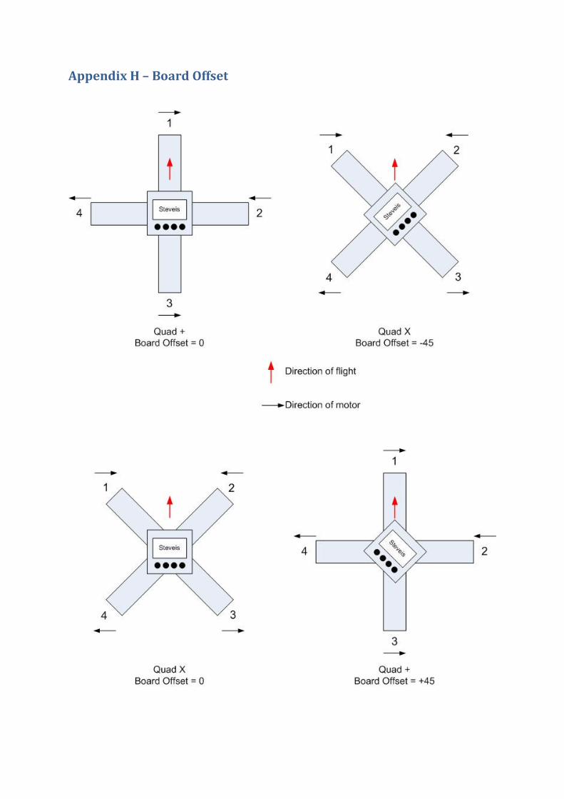
• Board Offset (see Appendix H)
o 0 – Zero degrees offset. KK2.1.X board faces forward.
o +45 – KK2.1.X board is mounted 45 degrees clockwise (top left corner points in
direction of flight).
o -45 – KK2.1.X board is mounted 45 degrees anticlockwise (top right corner points in
direction of flight).
• Spin on Arm
o No – When armed, with throttle at zero, motors are stopped.
o Yes – When armed and throttle is at zero, motors run at the speed set by Minimum
Throttle. This is useful if you want to fly and never want your motors to stop in flips
and rolls for example.
• SS Gimbal
o No – A normal camera gimbal is being used with one servo for Pitch and one for Roll.
o Yes – Super Simple Gimbal is used where both servos work together to move Pitch
and Roll in a differential configuration.
• Gimbal Control
o No – Gimbal offset is fixed as set in Camera Stab Settings.
o Aux – Gimbal Pitch offset can be changed using the Aux channel (see Appendix B).
This enables you to change the Pitch offset with a Standard PPM receiver.
o 6&7 – Gimbal Pitch and Roll offset can be changed using the receiver Channel 6 and
7 outputs. Note that you will need to use this feature with a CPPM receiver, satellite
receiver or SBus receiver.
• Alt Safe Screen
o No – Standard SAFE screen layout
o Yes – Alternative SAFE screen layout which displays the last Motor Layout selected
(this is just a guide as you may have changed the settings in the Mixer Editor).
• Batt Volt Trim
o Enables you to adjust the battery voltage reading by 0.1 volt increments if you are
not satisfied with the value shown with the default trim value of 0. The range is +/-
0.6 volts.

Self-level Settings
Self Level Settings are independent from normal PI settings.
• P Gain – The power of the self-levelling. Higher number is stronger. Too high will cause
oscillations. To low and it’s slow to self level.
• P limit – Limits the max power of self levelling. Higher number is higher limit.
• ACC Trim Roll – compensates for self level drift when the KK2.1.X had the ACC calibrated
when it wasn’t exactly level.
• ACC Trim Pitch – compensates for self level drift when the KK2.1.X had the ACC calibrated
when it wasn’t exactly level.
• It’s better to calibrate the ACC with the KK2.1.X level rather than use the trims. Make sure
the KK2.1.X is mounted level in the multicopter.
Camera Stab Settings
Various settings
• Roll gain – when set to zero, camera gimbal is disabled and motor output (M7 & M8) can be
used for a motor/servo output as configured by Motor Layout / Mixer Editor. If using a
camera gimbal, increase this value to enable servo movement. Start with a value around
500. If the servo moves in the wrong direction, change to a negative value.
• Roll offset – percentage of Roll servo offset. Default is 50%. Keep this value as close to 50%
as possible. Move the servo horn rather than adjusting the offset.
• Pitch gain – when set to zero, camera gimbal is disabled and motor output (M7 & M8) can be
used for a motor/servo output as configured by Motor Layout / Mixer Editor. If using a
camera gimbal, increase this value to enable servo movement. Start with a value around
500. If the servo moves in the wrong direction, change to a negative value.
• Pitch offset – percentage of Pitch servo offset. Default is 50%. Keep this value as close to
50% as possible. Move the servo horn rather than adjusting the offset.
• Trick to map receiver outputs to motor outputs – If you have a CPPM, Satellite or SBus
receiver and you’re not using outputs M7 or M8, you can mirror Ch6 & Ch7 to the M7 & M8
outputs by setting both the Roll and Pitch gains to 1 and selecting Misc. Settings 2, Gimbal
Control, “6&7”. You could then connect a receiver controlled switch to M7 and/or M8 and
control it using your transmitter.
MPU6050 Settings
Various sensor settings
• Gyro (deg/sec) – Selects the full-scale range of the three axis gyroscope of ±250, ±500,
±1000, and ±2000°/sec. The lower the value, the better the resolution. However, if you
exceed the gyro range during flight, the multicopter will spin quickly and lose orientation (so
self level will not work properly). Keep this value low for accurate flight, eg FPV. Beginners
should stick with the default of 500. Experienced acrobatic flyers should increase this value
to 2000 to ensure they do not exceed the range during their manoeuvres.
• Acc (+/- g) – Selects the full-scale range of the three axis accelerometer of ±2g, ±4g, ±8g and
±16g. The lower the value, the better the resolution. Keep this value low for accurate flight,
eg FPV. Beginners should stick with the default of 4. Note, if you change this value, you will
have to calibrate the ACC again.
• Filter (Hz) – Digital low pass filter applied to gyro and accelerometer. The higher the value,
the less filtering is applied to the sensor readings. Lower values smooth the sensor reading
out over time. This causes problems with the PI control loop while masking vibrations. It is
best to leave this value at 256 and fix your vibration problems (balance props etc).
• Changing any of the above settings may require small changes to your PI settings.
• Ideal FPV settings for extremely accurate flying with a balanced multicopter would be with
Self Level on, a gyroscope rate of ±250°/sec, an accelerometer rate of ±2g and a filter setting
of 256Hz. In reality, to allow some freedom, the settings may be ±500°/sec and ±4g.
• Ideal acro settings to allow extreme manoeuvres would be with Self Level off, a gyroscope
rate of ±2000°/sec, an accelerometer rate of ±16g and a filter setting of 256Hz.
Sensor Test
Displays the raw gyroscope and accelerometer sensor values.
• Must show "OK" when stationary.
• If it says “Not OK” when stationary, the sensor chip is faulty.
• Move the KK2.1.X around to see that the numbers change. In this case, it is fine if the
sensors start reading “Not OK”.
Sensor Max Min
Displays the maximum and minimum sensor values recoded during flight, when self level is off.
• Turn Self Level On.
• Arm and take off.
• Turn Self Level Off.
• Now fly to get the KK2.1.X to record the maximum sensor values.
• Turn Self Level On.
• Land and Disarm.
• Check results.
• It’s ok for the accelerometer values to hit their maximum values but if your gyro values
are at maximum then you should increase your Gyro (deg/sec) value in MPU6050
Settings.
ACC Calibration
Calibrates the accelerometers
• Set the multicopter level.
• Invoke the acc calibration routine.
• Do not move the multicopter during calibration.
• You will not be able to Arm the KK2.1.X until the calibration routing has been successful.
• If the calibration failed and you did not move the multicopter during calibration then you
have a faulty sensor chip.
Receiver Channel Map If you have a CPPM, Satellite or SBus receiver, you will probably need to change the channel
mapping. The default is for Futaba receivers that have the channel order Aileron, Elevator, Throttle,
Rudder and Aux (1,2,3,4,5). Spektrum uses the order Throttle, Elevator, Aileron, Rudder, Aux
(3,2,1,4,5). You can select any channel from 1 to 8 for the mapping.
If you have a standard receiver, you can switch the inputs around. This may be useful if you have a
failed input and want to use the Aux input instead. Say the Aileron input doesn’t appear to work. In
Receiver Channel Map, change Roll to 5 and AUX to 1. Then plug the receiver Roll output to the Aux
input. To enable this feature for a standard receiver, Mode Settings, Channel Map must be set to
“Yes”.
Mixer Editor This menu lets you adjust where and how much signal the motors gets from the sticks and sensors.
This enables you to make any configuration possible, with up to 8 motors or servos.
To change between the output channels 1-8, press CHANGE when the upper right number is
highlighted.
• Throttle – Amount of throttle command. Usually 100% if the output channel is connected to
an ESC.
• Aileron – Amount of aileron/roll command. Use positive value for motors on the right side of
the roll axis, and negative for the left side of the roll axis. The value is given by the motor's
distance from the roll axis. More is further away.
• Elevator – Amount of elevator/pitch command. Use positive value for motors on the front
side of the pitch axis, and negative for the back side of the pitch axis. The value is given by
the motor's distance from the pitch axis. More is further away.
• Rudder – Amount of rudder/yaw command. Usually 100%. Use a positive value for a CW
spinning propeller, and negative for a CCW spinning propeller. This is a very important
setting for reversing the servo direction on tricopters. If your tricopter starts to pirouette on
take off, select the channel that the servo is connected to (usually output 4 or 7) and change
the Rudder value from +100 to -100.
• Offset – Applies a constant offset to the channel. Keep this zero when it is an ESC channel,
and around 50% when connected to a servo. Fine tune servo position by adjusting this value.
• Type – Set it to the type (servo or ESC) connected to the channel.
o For ESC: Output PWM rate is always high. Normally outputs zero when disarmed or
throttle is at idle. Applies the "Minimum Throttle" value from the "Misc. Settings 1"
sub-menu when armed and throttle is above zero or when Spin on Arm is “Yes”.
o For Servo: Output PWM rate can be high or low. Outputs the offset value when
disarmed.
• Rate – High rate (400Hz) for ESC or digital servos, or low rate (50Hz) for analogue servos.
• See Appendix F for more information.
Show Motor Layout Displays a graphical representation of the motors and servos
• Can be used to check the Motor direction and which outputs to connect the ESCs and Servos
to. Note that this does not set the motor direction. That is set by the wires connected
between your motor and ESC. If you need to reverse your motor, reverse two of the three
motor wires.
• Enables you to see which Motor Layout you have selected and any changes you make in the
Mixer Editor.
Load Motor Layout
Enables you to load a preconfigured multicopter setup.
• Select from a list of preconfigured multicopter types.
• “Tricopter Servo M7” uses M7 for the servo which is almost jitter free.
• You will not be able to Arm the KK2.1.X until you have selected a Motor Layout.
• When loading the firmware, after a Factory Reset or Resetting a Profile, you will need to
select a Motor Layout.
Output Sliders
Displays a graphical representation of the signals on the outputs
• Shows signals applied to the outputs as if the KK2.1.X was armed.
• Unfortunately, it does not show Camera Gimbal signals on M7 & M8.
Gyro Bubble
Displays a graphical display of the gyroscope.
• This could be used to check for vibrations but you would need to connect the motor ESCs
direct to a receiver. This is very dangerous and needs to be done with caution.
• The bubble should be in the centre of the crosshair. If it is not, arm and disarm the KK2.1.X
to calibrate the gyro.
• Moving the board will demonstrate the sensitivity of the gyro at different settings.
• The gyro bubble may drift over time or if the temperature changes.
Acc Bubble
Displays a graphical display of the accelerometer.
• When level, the bubble should be in the middle of the crosshair. If not, the ACC Calibration
routine should be performed.
• Moving the board will demonstrate the sensitivity of the accelerometer at different settings.
• The accelerometer bubble may drift if the temperature changes.
End Point Limits
Sets the end points for servos connected to the outputs.
• Set the minimum and maximum servo throw for outputs with servos connected.
• It is recommended to leave these values at 0% and 100% and mechanically adjust your
linkage connections on your servo arms to achieve the desired throws.
Profiles
Enables the use of two user profiles to store settings
• Current Profile
o P1 – Profile 1 selected (will be forced to P1 if you select “Yes” for Switch SS & PI).
o P2 – Profile 2 selected.
• Each Profile has all of its own settings, including Receiver type, Motor Layout and ACC
Calibration which will need to be set up and calibrated before you can arm the board when
the profile is selected.
• You will need to power cycle the KK2.1.X if you change to a profile with a different type of
Receiver.
• The SAFE screen will display P1 or P2 in the top left of the display to indicate which profile is
being used.
• Switch SS & PI
o No – Enables you to select either Profile 1 or Profile 2.
o Yes – Forces you to use Profile 1 as the main profile. However, when you switch the
Aux switch, it will use the Stick Scaling and PI settings from Profile 2. If you don’t
want to use Self Level when switching to the Stick Scaling and PI settings from P2
you can set Self Level P Gain to zero in P2 or you can set Self Level to “Stick” in P1.
• To setup the Stick Scaling and PI Gains and Limits in P2, you first have to set Switch SS & PI to
“No” so that you can set the Current Profile to “P2”. It is not necessary to select a motor
layout or ACC calibrate P2 if using this feature. If you leave the PI settings the same in both
profiles but change the Stick Scaling, switching will act like dual rates on your transmitter.
• The SAFE screen will display PI1 or PI2 in the top left of the display to indicate which set of
Stick Scaling and PI settings are being used, depending on the setting of the Aux
channel/switch. You will also see if self level switches On or Off when switching between PI1
and PI2.
• Reset Profile 1
o Factory Reset Profile 1 settings.
• Reset Profile 2
o Factory Reset Profile 1 settings.
• Copy P1 to P2
o Copy all P1 settings to P2
• Copy P2 to P1
o Copy all P2 settings to P1

Debug
Various values used for debugging purposes.
Version
Displays current firmware version information.
Factory Reset
Perform a complete factory reset on all profiles.
Appendix A – SAFE Screen Information
Pre-flight:
• If the SAFE screen says ERROR, you must fix that error before you can arm it.
• You will see the actual error on the display.
• You may have to power cycle the KK2.1.X to clear an error after fixing it.
• Top right displays the profile being used (P1 or P2) or tells you which stick scaling and PI
profile you are using (PI1 or PI2).
• It will tell you if Self Level is on or off.
• The Battery (Batt) voltage will be displayed if you have connected the flight battery +ve to
the KK2.1.X battery monitor pin (pin closest to the edge of the board).
• Temp is the MPU6050 internal temperature.
• Roll and Pitch Angle will appear after arming and disarming. They display the angle of the
KK2.1.X after arming and disarming.
• If you have the Alternative SAFE screen layout selected in Misc Settings 2, it displays the last
Motor Layout selected (this is just a guide as you may have changed the settings in the Mixer
Editor).
• Pressing button 4 takes you into the MENU.
Post-flight:
• If the SAFE screen says ERROR, you must pay attention.
• You will see the actual ERROR on the display. It will most likely be “Error: no yaw input”
which means you had a receiver failure during flight.
• The top left corner will display a number if the KK2.1.X code took longer than expected to
execute during flight, the number of times this happened will be displayed. This shouldn’t
happen. If it does, it could indicate a fault with the board.
• The Roll and Pitch Angle will appear.
• Pressing button 4 takes you into the MENU.
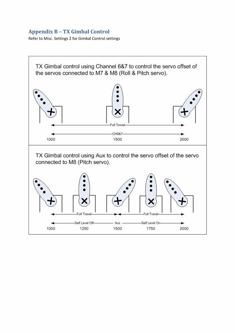
Appendix B – TX Gimbal Control
Refer to Misc. Settings 2 for Gimbal Control settings
Appendix C – Misc Features
The below features do not have any menu options.
• Binding satellite receivers
o You have to bind a satellite receiver to the KK2.1.X for it to work correctly.
o You may need to set up your transmitter to support DSM2 or DSMX.
o To bind a DSM2 satellite receiver, hold down buttons 2&3 on power up.
o To bind a DSMX satellite receiver, hold down button 3 on power up.
• Almost jitter free servos on M7 & M8 – The code supports almost jitter free servos on
outputs 7 & 8. This is to improve servo operation on camera gimbals or tricopters.
• Servo control when armed and throttle is at zero – This stops servos automatically
centring when flying and you place the throttle at zero.
Appendix D – Problems with Self Level
The following will cause accuracy issues with Self Level.
• Vibrations are the most common cause – balance your propellers, including the hubs.
Balance your motor bells. Ensure you don’t have bent motor shafts. Ensure the engineering
quality of your prop adaptors is acceptable. Finally, dynamically balance your motor with
prop and prop adaptor.
• Arming outside the 20deg limit – arm the multicopter when it is level.
• Exceeding gyro rate while flying – ensure the gyro rate is higher than your expected
manoeuvres. This will cause catastrophic issues if self level is switch on as the KK2.1.X will
have no idea which way is up.
• Temperature changes – let your multicopter acclimatise to the temperature you are going to
fly in before arming.
• Drifting gyro – gyros drift over a short period of time (minutes). During long flights, you may
need to land and rearm to recalibrate the gyros.
• Receiver selection – see Appendix E.

Appendix E – Receiver selection
To achieve the most accurate flight characteristics, the order of preference for Receiver selection is:
• Standard
• CPPM
• DSM Satellite
• SBus
The reason for the above is the interrupt processing that is required to process the receiver channel
output increases as you go down the list. Interrupts that occur during the software PWM loop that
generates the output pulses on M1 to M8 need to be kept as short as possible to minimise the jitter.
Standard receivers will cause the least jitter, SBus the most. It also causes jitter in the self level
calculation resulting in the KK2.1.X knowing exactly which way is “up”.
If you only have motors and don’t use Self Level, you probably won’t notice any issues with SBus.
If you have servos connected to M1-M6 you will notice some jitter with Satellites and SBus.
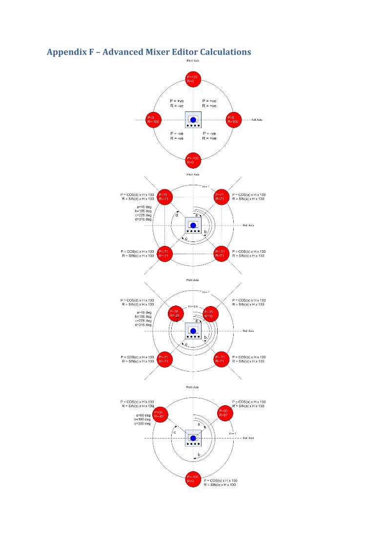
Appendix F – Advanced Mixer Editor Calculations
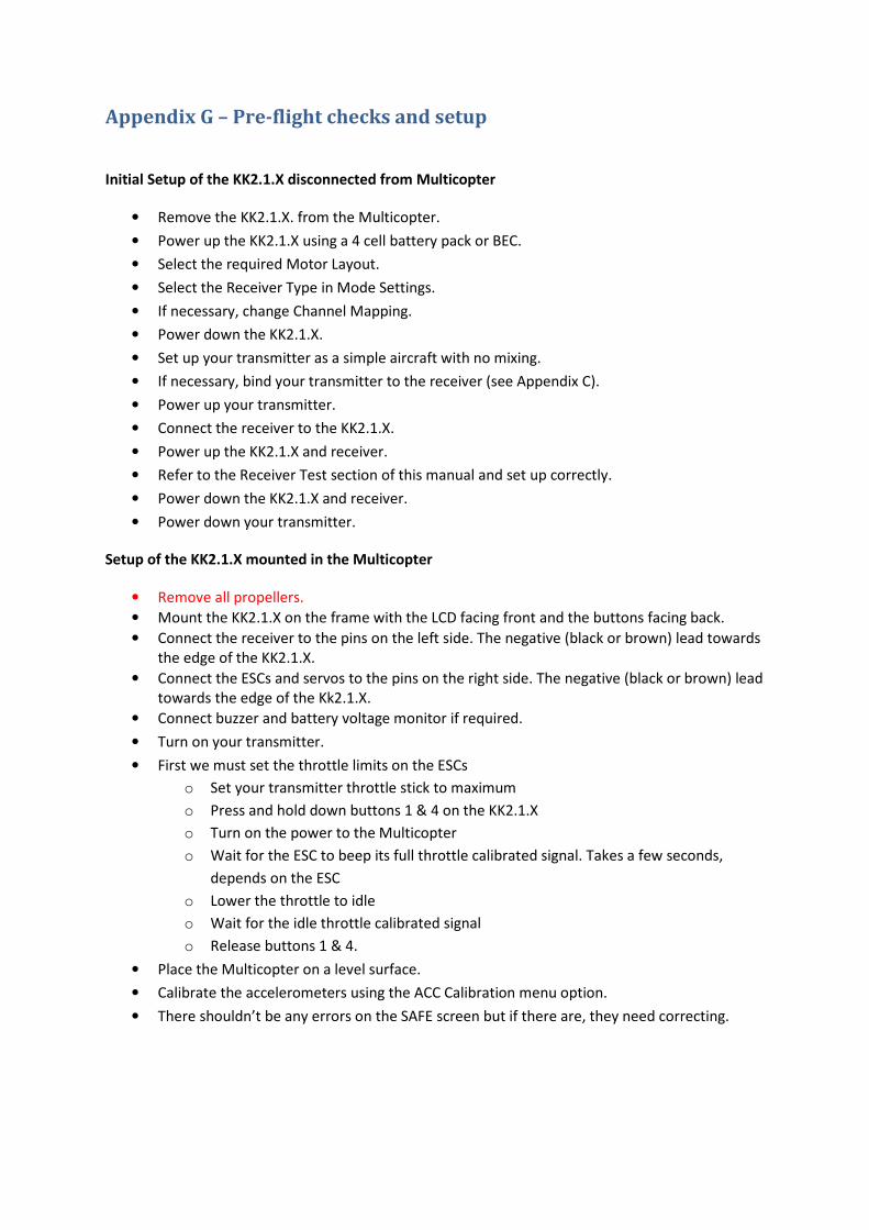
Appendix G – Pre-flight checks and setup
Initial Setup of the KK2.1.X disconnected from Multicopter
• Remove the KK2.1.X. from the Multicopter.
• Power up the KK2.1.X using a 4 cell battery pack or BEC.
• Select the required Motor Layout.
• Select the Receiver Type in Mode Settings.
• If necessary, change Channel Mapping.
• Power down the KK2.1.X.
• Set up your transmitter as a simple aircraft with no mixing.
• If necessary, bind your transmitter to the receiver (see Appendix C).
• Power up your transmitter.
• Connect the receiver to the KK2.1.X.
• Power up the KK2.1.X and receiver.
• Refer to the Receiver Test section of this manual and set up correctly.
• Power down the KK2.1.X and receiver.
• Power down your transmitter.
Setup of the KK2.1.X mounted in the Multicopter
• Remove all propellers.
• Mount the KK2.1.X on the frame with the LCD facing front and the buttons facing back.
• Connect the receiver to the pins on the left side. The negative (black or brown) lead towards
the edge of the KK2.1.X.
• Connect the ESCs and servos to the pins on the right side. The negative (black or brown) lead
towards the edge of the Kk2.1.X.
• Connect buzzer and battery voltage monitor if required.
• Turn on your transmitter.
• First we must set the throttle limits on the ESCs
o Set your transmitter throttle stick to maximum
o Press and hold down buttons 1 & 4 on the KK2.1.X
o Turn on the power to the Multicopter
o Wait for the ESC to beep its full throttle calibrated signal. Takes a few seconds,
depends on the ESC
o Lower the throttle to idle
o Wait for the idle throttle calibrated signal
o Release buttons 1 & 4.
• Place the Multicopter on a level surface.
• Calibrate the accelerometers using the ACC Calibration menu option.
• There shouldn’t be any errors on the SAFE screen but if there are, they need correcting.
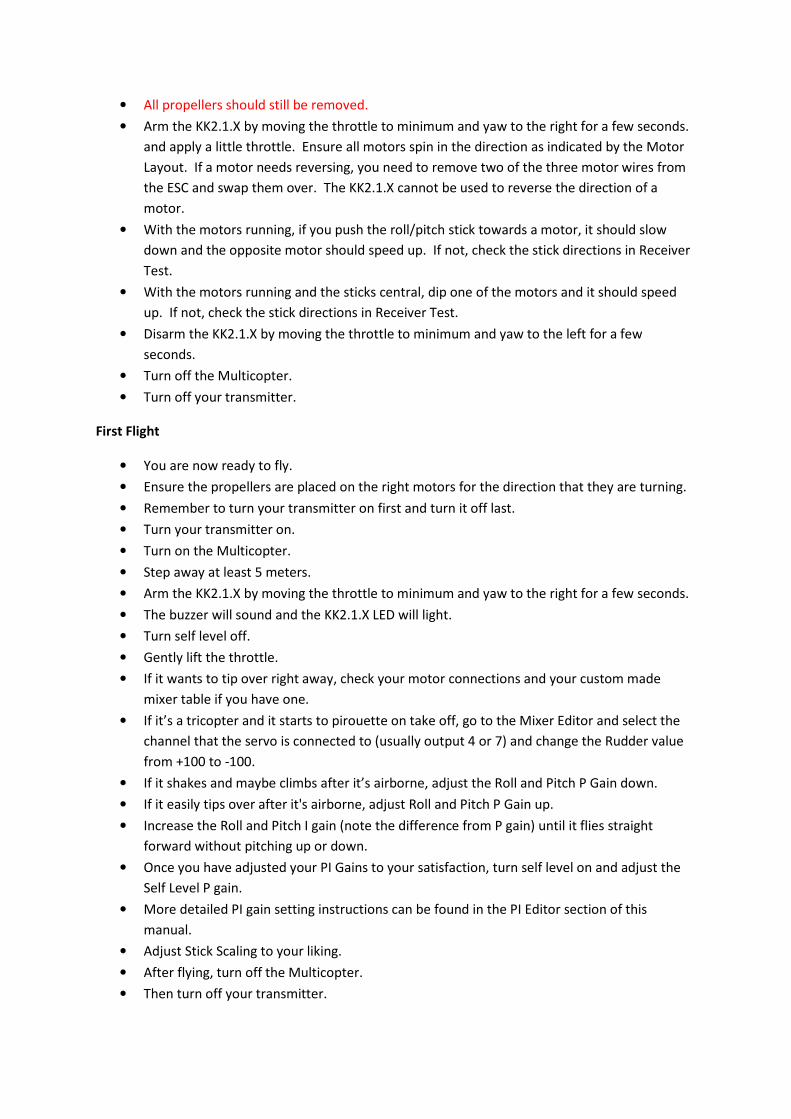
• All propellers should still be removed.
• Arm the KK2.1.X by moving the throttle to minimum and yaw to the right for a few seconds.
and apply a little throttle. Ensure all motors spin in the direction as indicated by the Motor
Layout. If a motor needs reversing, you need to remove two of the three motor wires from
the ESC and swap them over. The KK2.1.X cannot be used to reverse the direction of a
motor.
• With the motors running, if you push the roll/pitch stick towards a motor, it should slow
down and the opposite motor should speed up. If not, check the stick directions in Receiver
Test.
• With the motors running and the sticks central, dip one of the motors and it should speed
up. If not, check the stick directions in Receiver Test.
• Disarm the KK2.1.X by moving the throttle to minimum and yaw to the left for a few
seconds.
• Turn off the Multicopter.
• Turn off your transmitter.
First Flight
• You are now ready to fly.
• Ensure the propellers are placed on the right motors for the direction that they are turning.
• Remember to turn your transmitter on first and turn it off last.
• Turn your transmitter on.
• Turn on the Multicopter.
• Step away at least 5 meters.
• Arm the KK2.1.X by moving the throttle to minimum and yaw to the right for a few seconds.
• The buzzer will sound and the KK2.1.X LED will light.
• Turn self level off.
• Gently lift the throttle.
• If it wants to tip over right away, check your motor connections and your custom made
mixer table if you have one.
• If it’s a tricopter and it starts to pirouette on take off, go to the Mixer Editor and select the
channel that the servo is connected to (usually output 4 or 7) and change the Rudder value
from +100 to -100.
• If it shakes and maybe climbs after it’s airborne, adjust the Roll and Pitch P Gain down.
• If it easily tips over after it's airborne, adjust Roll and Pitch P Gain up.
• Increase the Roll and Pitch I gain (note the difference from P gain) until it flies straight
forward without pitching up or down.
• Once you have adjusted your PI Gains to your satisfaction, turn self level on and adjust the
Self Level P gain.
• More detailed PI gain setting instructions can be found in the PI Editor section of this
manual.
• Adjust Stick Scaling to your liking.
• After flying, turn off the Multicopter.
• Then turn off your transmitter.
Appendix H – Board Offset

Appendix I – Powering the KK2.1.X
The KK2.1.X has two 5V power busses.
The first 5V bus is common across the receiver inputs, output 1 (M1) and the programmer port. This
bus powers the KK2.1.X processor and needs to be as clean as possible (i.e. no noise from servos).
The second 5V bus is common for outputs 2 to 8 (M2 to M8) only.
You shouldn’t connect the two 5V busses together as any noise on outputs 2 to 8 will then be
present on the KK2.1.X CPU power supply.
ESCs don’t generally need a 5V power supply but servos do. Therefore, if a servo is connected to M2
to M8, it will also need a 5V power supply.
Usually, an ESC with a 5V BEC will be connected to M1 which will power the receiver and the KK2.1.X
board. Servos on the M2 to M8 5V bus will need another ESC with a 5V BEC to be connected to M2
to M8. Note, you could run the M2 to M8 power bus at 6V if you wanted to.
In general, only one BEC should be connected to M2 to M8. In the case of a quadcopter, you will
have three ESCs connected to M2, M3 & M4. If they have switching BECs, their 5V wires should not
be connected together on the M2 to M8 power bus. Therefore, remove all 3 red wires from the
servo connector and put some heat shrink over each one (leave one BEC on M2 to M4 if you need to
power a servo on M5, M6, M7 and/or M8). ESCs with linear BECs are ok to leave the 5V wire in the
servo connector. If in doubt, remove the 5V wire.
Some ESCs don’t have an internal BEC so you will need to use an external UBEC. If you already have
an ESC (without a BEC) plugged into M1, you have the following options to power the KK2.1.X and
receiver.
• Connect the UBEC to a spare receiver channel. This will power the receiver and the
KK2.1.X via the cable that connects the receiver and KK2.1.X.
• Use the Mixer Editor and copy the M1 settings to M5 (or any spare output). Connect the
ESC for motor 1 that your would have connected to M1 (output 1) to the new motor
output you just configured. Now, you can connect your UBEC to M1.
• Use a servo Y lead to connect both the ESC and UBEC to M1.
Some ESCs have low current BECs which have been known to “brown out” when large motor
currents are drawn. If this happens, the KK2.1.X will reboot and therefore results in a crash. If you
are concerned that this could happen, you should use an external UBEC and connect as above.

Special note for Castle Creation ESC’s created specifically for multicopters
Castle Creations have created a pack of four ESCs. You get three ESCs without a BEC and one with a
BEC so you don’t need to remove the 5V wire from the ESCs connected to M2 to M8.
The ESC with a BEC will be connected to M1 so that it powers the KK2.1.X and receiver. The problem
is that the other ESCs need a 5V signal “up the servo connector” in order for them to work. If they
are plugged into M2 to M8, they don’t get 5V and therefore, won’t work! Strictly, you should use a
UBEC on a spare M2 to M8 output to power the other ESCs. However, providing you don’t have any
servos, you may want to consider bridging the M1 and M2 to M8 5V power busses.
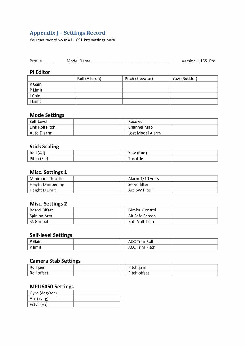
Appendix J – Settings Record
You can record your V1.16S1 Pro settings here.
Profile ______ Model Name ___________________________________ Version 1.16S1Pro
PI Editor Roll (Aileron) Pitch (Elevator) Yaw (Rudder)
P Gain
P Limit
I Gain
I Limit
Mode Settings Self-Level Receiver
Link Roll Pitch Channel Map
Auto Disarm Lost Model Alarm
Stick Scaling Roll (Ail) Yaw (Rud)
Pitch (Ele) Throttle
Misc. Settings 1 Minimum Throttle Alarm 1/10 volts
Height Dampening Servo filter
Height D Limit Acc SW filter
Misc. Settings 2 Board Offset Gimbal Control
Spin on Arm Alt Safe Screen
SS Gimbal Batt Volt Trim
Self-level Settings P Gain ACC Trim Roll
P limit ACC Trim Pitch
Camera Stab Settings Roll gain Pitch gain
Roll offset Pitch offset
MPU6050 Settings Gyro (deg/sec)
Acc (+/- g)
Filter (Hz)

Receiver Channel Map Roll (Ail)
Pitch (Ele)
Throttle
Yaw (Rud)
AUX
Mixer Editor 1 2 3 4 5 6 7 8
Throttle
Aileron
Elevator
Rudder
Offset
Type
Rate
End Point Limits Min Max Min Max
1 5
2 6
3 7
4 8
Profiles Current Profile
Switch SS & PI