e844 3ph - .net framework
TRANSCRIPT

E844 3PH
EN
FR
DE
ES
NL
IT
PL
TR
PT
ZH
AR
RU
FAAC S.p.A. Soc. UnipersonaleVia Calari, 10 - 40069 Zola Predosa BOLOGNA - ITALYTel. +39 051 61724 - Fax +39 051 09 57 820www.faac.it - www.faacgroup.com
© Copyright FAAC S.p.A. from 2019. All rights reserved.No part of this manual may be reproduced, archived, distributed to third parties nor copied in any other way, in any format and with any means, be it electronic, mechanical or by photocopying, without prior written authorisation by FAAC S.p.A.All names and trademarks mentioned are the property of their respective manufacturers.Customers may make copies exclusively for their own use.This manual was published in 2019.
© Copyright FAAC S.p.A. del 2019. Todos los derechos están reservados.No puede reproducirse, archivarse, distribuirse a terceros ni copiarse de ningún modo, ninguna parte de este manual, con medios mecánicos o mediante fotocopia, sin el permiso previo por escrito de FAAC S.p.A.Todos los nombre y las marcas citadas son de propiedad de los respectivos fabricantes.Los clientes pueden realizar copias para su uso exclusivo.Este manual se ha publicado en 2019.
© Copyright FAAC S.p.A. van 2019. Alle rechten voorbehouden.Niets uit deze handleiding mag gereproduceerd, gearchiveerd, aan derden openbaar gemaakt of op andere wijze gekopieerd worden, in om het even welke vorm en met geen enkel middel, noch elektronisch, mechanisch of via fotokopiëren, zonder schrfitelijke toestemming vooraf van FAAC S.p.A.Alle vermelde namen en merken zijn eigendom van de respectievelijke fabrikanten.De klanten mogen kopieën maken die enkel voor eigen gebruik bestemd zijn.Dez handleiding werd in 2019 gepubliceerd.
© Copyright FAAC S.p.A. ab dem 2019. Alle Rechte vorbehalten.Kein Teil dieses Handbuchs darf reproduziert, gespeichert, an Dritte weiter-gegeben oder sonst auf eine beliebige Art in einem beliebigen Format und mit beliebigen Mitteln kopiert werden, weder mit elektronischen, noch me-chanischen oder durch Fotokopieren, ohne die Genehmigung von FAAC S.p.A.Alle erwähnten Namen und Marken sind Eigentum der jeweiligen Hersteller.Die Kunden dürfen nur für den Eigengebrauch Kopien anfertigen.Dieses Handbuch wurde 2019 veröffentlicht.
© Copyright FAAC S.p.A. depuis 2019. Tous droits réservés.Aucune partie de ce manuel ne peut être reproduite, archivée ou distribuée à des tiers ni copiée, sous tout format et avec tout moyen, qu’il soit électro-nique, mécanique ou par photocopie, sans le consentement écrit préalable de FAAC S.p.A.Tous les noms et les marques cités sont la propriété de leurs fabricants respectifs.Les clients peuvent faire des copies pour leur usage exclusif.Ce manuel a été publié en 2019.
© Copyright FAAC S.p.A. dal 2019. Tutti i diritti riservati.Nessuna parte di questo manuale può essere riprodotta, archiviata, distribuita a terzi né altrimenti copiata, in qualsiasi formato e con qualsiasi mezzo, sia esso elettronico, meccanico o tramite fotocopia, senza il preventivo consenso scritto di FAAC S.p.A.Tutti i nomi e i marchi citati sono di proprietà dei rispettivi fabbricanti.I clienti possono effettuare copie per esclusivo utilizzo proprio.Questo manuale è stato pubblicato nel 2019.

E844 3PH 1 532315 - Rev.A
Tran
slatio
n of
the
orig
inal
inst
ruct
ions
ENGLIS
H
CONTENTSEU Declaration of conformity . . . . . . . . . . . . . . . . . . . . . . . . . . . 2
1. INTRODUCTION TO THIS INSTRUCTION MANUAL . . . . . 21.1 Meaning of the symbols used . . . . . . . . . . . . . . . . . . . . . . . . . 3
2. SAFETY RECOMMENDATIONS . . . . . . . . . . . . . . . . . . . . . . . . . 42.1 Installer safety . . . . . . . . . . . . . . . . . . . . . . . . . . . . . . . . . . . . . . . 42.2 Storage . . . . . . . . . . . . . . . . . . . . . . . . . . . . . . . . . . . . . . . . . . . . . . 42.3 Waste disposal . . . . . . . . . . . . . . . . . . . . . . . . . . . . . . . . . . . . . . . 4
3. E844 3PH . . . . . . . . . . . . . . . . . . . . . . . . . . . . . . . . . . . . . . . . . . . . . . 53.1 Intended use . . . . . . . . . . . . . . . . . . . . . . . . . . . . . . . . . . . . . . . . . 53.2 Limitations of use . . . . . . . . . . . . . . . . . . . . . . . . . . . . . . . . . . . . 53.3 Unauthorised use . . . . . . . . . . . . . . . . . . . . . . . . . . . . . . . . . . . . 53.4 Product identification . . . . . . . . . . . . . . . . . . . . . . . . . . . . . . . . . 53.5 Technical specifications . . . . . . . . . . . . . . . . . . . . . . . . . . . . . . . 5
4. INSTALLATION REQUIREMENTS . . . . . . . . . . . . . . . . . . . . . . . 64.1 Electrical system . . . . . . . . . . . . . . . . . . . . . . . . . . . . . . . . . . . . . 6
5. INSTALLATION . . . . . . . . . . . . . . . . . . . . . . . . . . . . . . . . . . . . . . . . 65.1 Tools required . . . . . . . . . . . . . . . . . . . . . . . . . . . . . . . . . . . . . . . . 65.2 Components . . . . . . . . . . . . . . . . . . . . . . . . . . . . . . . . . . . . . . . . . 75.3 Connections . . . . . . . . . . . . . . . . . . . . . . . . . . . . . . . . . . . . . . . . . 8
Control devices . . . . . . . . . . . . . . . . . . . . . . . . . . . . . . . . . . . . . . . . 8Accessories power supply . . . . . . . . . . . . . . . . . . . . . . . . . . . . . . . 9Outputs . . . . . . . . . . . . . . . . . . . . . . . . . . . . . . . . . . . . . . . . . . . . . . . 9Failsafe . . . . . . . . . . . . . . . . . . . . . . . . . . . . . . . . . . . . . . . . . . . . . . . . 9Limit switches . . . . . . . . . . . . . . . . . . . . . . . . . . . . . . . . . . . . . . . . . 9Flashing light . . . . . . . . . . . . . . . . . . . . . . . . . . . . . . . . . . . . . . . . . . 9BUS 2easy devices . . . . . . . . . . . . . . . . . . . . . . . . . . . . . . . . . . . . 10Radio receiver/decoder board . . . . . . . . . . . . . . . . . . . . . . . . . . 10Motor . . . . . . . . . . . . . . . . . . . . . . . . . . . . . . . . . . . . . . . . . . . . . . . . 10Connecting the earth . . . . . . . . . . . . . . . . . . . . . . . . . . . . . . . . . . 10Mains power supply . . . . . . . . . . . . . . . . . . . . . . . . . . . . . . . . . . . 10
6. SET-UP . . . . . . . . . . . . . . . . . . . . . . . . . . . . . . . . . . . . . . . . . . . . . . . 116.1 Programming . . . . . . . . . . . . . . . . . . . . . . . . . . . . . . . . . . . . . . . 116.2 Operating logics . . . . . . . . . . . . . . . . . . . . . . . . . . . . . . . . . . . . . 136.3 Setup. . . . . . . . . . . . . . . . . . . . . . . . . . . . . . . . . . . . . . . . . . . . . . . 146.4 Restore the default values. . . . . . . . . . . . . . . . . . . . . . . . . . . . 14
7. PUTTING INTO SERVICE . . . . . . . . . . . . . . . . . . . . . . . . . . . . . . 147.1 Final checks . . . . . . . . . . . . . . . . . . . . . . . . . . . . . . . . . . . . . . . . . 147.2 Close the enclosure . . . . . . . . . . . . . . . . . . . . . . . . . . . . . . . . . . 147.3 Final operations . . . . . . . . . . . . . . . . . . . . . . . . . . . . . . . . . . . . . 14
8. ACCESSORIES . . . . . . . . . . . . . . . . . . . . . . . . . . . . . . . . . . . . . . . . . 158.1 Closing photocells . . . . . . . . . . . . . . . . . . . . . . . . . . . . . . . . . . . 158.2 Sensitive edges . . . . . . . . . . . . . . . . . . . . . . . . . . . . . . . . . . . . . 158.3 BUS 2easy devices . . . . . . . . . . . . . . . . . . . . . . . . . . . . . . . . . . . 16
Connection . . . . . . . . . . . . . . . . . . . . . . . . . . . . . . . . . . . . . . . . . . . 16BUS 2easy photocells . . . . . . . . . . . . . . . . . . . . . . . . . . . . . . . . . . 16BUS 2easy control devices . . . . . . . . . . . . . . . . . . . . . . . . . . . . . 16BUS 2easy device registration . . . . . . . . . . . . . . . . . . . . . . . . . . 17
9. DIAGNOSTICS . . . . . . . . . . . . . . . . . . . . . . . . . . . . . . . . . . . . . . . . 189.1 Firmware version . . . . . . . . . . . . . . . . . . . . . . . . . . . . . . . . . . . . 189.2 LEDs check . . . . . . . . . . . . . . . . . . . . . . . . . . . . . . . . . . . . . . . . . . 189.3 Automated system status . . . . . . . . . . . . . . . . . . . . . . . . . . . . 189.4 Alarms/Errors . . . . . . . . . . . . . . . . . . . . . . . . . . . . . . . . . . . . . . . 18
10. MAINTENANCE . . . . . . . . . . . . . . . . . . . . . . . . . . . . . . . . . . . . . . 1910.1 Routine maintenance . . . . . . . . . . . . . . . . . . . . . . . . . . . . . . . 19
TABLES1 Symbols: notes and warnings on the instructions . . . . . . 32 Symbols: personal protective equipment . . . . . . . . . . . . . . 33 Symbols: safety signs and symbols (EN ISO 7010) . . . . . . 34 Technical data E844 3PH . . . . . . . . . . . . . . . . . . . . . . . . . . . . . 55 Assigning an address to the photocells.. . . . . . . . . . . . . . 166 Addressing control devices . . . . . . . . . . . . . . . . . . . . . . . . . 167 Status of the LEDs . . . . . . . . . . . . . . . . . . . . . . . . . . . . . . . . . 188 Automated system status . . . . . . . . . . . . . . . . . . . . . . . . . . 189 Alarms/Errors . . . . . . . . . . . . . . . . . . . . . . . . . . . . . . . . . . . . . 1810 Scheduled maintenance . . . . . . . . . . . . . . . . . . . . . . . . . . . 19

E844 3PH 2 532315 - Rev.A
Tran
slatio
n of
the
orig
inal
inst
ruct
ions
ENGLIS
H1. INTRODUCTION TO THIS
INSTRUCTION MANUAL
This manual provides the correct procedures and requirements for installing E844 3PH and maintaining it in a safe condition.When drafting the manual, the results of the risk assessment conducted by FAAC S.p.A. on the entire product life cycle have been taken into account in order to implement effective risk reduction measures.The following stages of the life cycle of the product have been considered:
- Delivery/handling- Assembly and installation- Set-up and commissioning- Operation- Maintenance/troubleshooting- Disposal at the end of the product’s life cycle
Risks arising from installation and using the product have been taken into consideration; these include:
- Risks for the installation/maintenance technician (technical personnel)
- Risks for the user of the automation system- Risks to product integrity (damage)
In Europe, the automation of a gate falls under the Ma-chinery Directive 2006/42/EC and the corresponding harmonised standards. Anyone automating a gate (new or existing) is classified as the Manufacturer of the Machine. They are therefore required by law, among other things, to carry out a risk analysis of the machine (automatic gate in its entirety) and take protective measures to fulfil the essential safety requirements specified in Annex I of the Machinery Directive.FAAC S.p.A. recommends that you always comply with the EN 12453 standard and in particular that you adopt the safety criteria and devices indicated, without exception, including the dead-man function. This manual also contains general information and guidelines, which are purely illustrative and not exhau-stive, in order to facilitate the activities carried out by the Manufacturer of the Machine in all respects with regard to carrying out the risk analysis and drafting the instructions for use and maintenance of the machine. It should be clearly understood that FAAC S.p.A. accepts no liability for the reliability and/ or completeness of the above instructions. As such, the manufacturer of the machine must carry out all the activities required by the Machinery Directive and the corresponding harmonised standards on the basis of the actual condi-tion of the locations and structures where the product E844 3PH will be installed, prior to commissioning the machine. These activities include the analysis of all the risks associated with the machine and subsequent implementation of all safety measures intended to fulfil the essential safety requirements.
EU DECLARATION OF CONFORMITY
The Manufacturer
Company name: FAAC S.p.A. Soc. Unipersonale
Address: Via Calari, 10 - 40069 Zola Predosa BOLOGNA - ITALY
hereby declares under its own exclusive liability that the fol-lowing product:
Description: electronic equipment
Model: E844 3PH
complies with the following applicable EU legislations:
2014/30/EU2014/35/EU2011/65/UE
Furthermore, the following harmonised standards have been applied:
EN 60335-1:2012 + A1:2014EN 61000-6-2:2005EN 61000-6-3:2007 + A1:2011
Other standards (applicable parts):
EN 60335-2-103:2015EN 13849-1:2015 CAT 2 PL “C”
Bologna, 01-10-2019 CEOA. Marcellan

E844 3PH 3 532315 - Rev.A
Tran
slatio
n of
the
orig
inal
inst
ruct
ions
ENGLIS
H
1.1 MEANING OF THE SYMBOLS USED
1 Symbols: notes and warnings on the instruc-tions
FWARNING ELECTRIC SHOCK HAZARD - The procedure or step described must be carried out following the instructions provided and according to the applicable safety regulations
!WARNING, PERSONAL INJURY HAZARD OR RISK OF DAM-AGE TO COMPONENTS - The procedure or step described must be carried out following the instructions provided and according to the applicable safety regulations.
WARNING - Details and specifications that must be complied with in order to ensure that the system oper-ates correctly.
RECYCLING AND DISPOSAL - The materials used in manu-facturing, the batteries and any electronic components must not be sent to landfill. They must be taken to authorised recycling and disposal centres
FIGURE E.g.: 1 -3 see Figure 1 - detail 3.
TABLE E.g.: 1 see Table 1.
§ CHAPTER/SECTION E.g.: §1.1 see section 1.1.
LED off
LED on
LED flashing
LED flashing quickly
2 Symbols: personal protective equipmentPersonal protective equipment must be worn to protect against hazards (e.g. crushing, cutting, shearing etc.):
Obligation to wear work gloves
Obligation to wear safety footwear
3 Symbols: safety signs and symbols (EN ISO 7010)
GENERIC HAZARDPersonal injury hazard or risk of damage to com-ponents
ELECTROCUTION HAZARDRisk of electric shock from live parts
BURNING OR SCALDING HAZARDRisk of burns or scalding due to the presence of high-temperature parts
RISK OF CUTTING/AMPUTATION/PUNCTURE - Cutting hazard due to the presence of sharp components or the use of pointed/sharp tools
RISK OF CRUSHING HANDS - Risk of crushing hands due to moving parts
RISK OF SHEARING - Risk of shearing due to moving parts
RISK OF IMPACT/CRUSHING/SHEARING - Risk of impact, crushing or shearing due to moving parts
This manual contains references to European stan-dards. The automation of a gate must fully comply with any laws, standards and regulations applicable in the country where installation will take place.
Unless otherwise specified, the measurements pro-vided in the instructions are in mm.
E844 3PH 4 532315 - Rev.A
Tran
slatio
n of
the
orig
inal
inst
ruct
ions
ENGLIS
H
Installation activities require special work conditions to reduce to the minimum the risks of accidents and serious damage. Furthermore, the suitable precau-tions must be taken to prevent risks of injury to persons or damage.
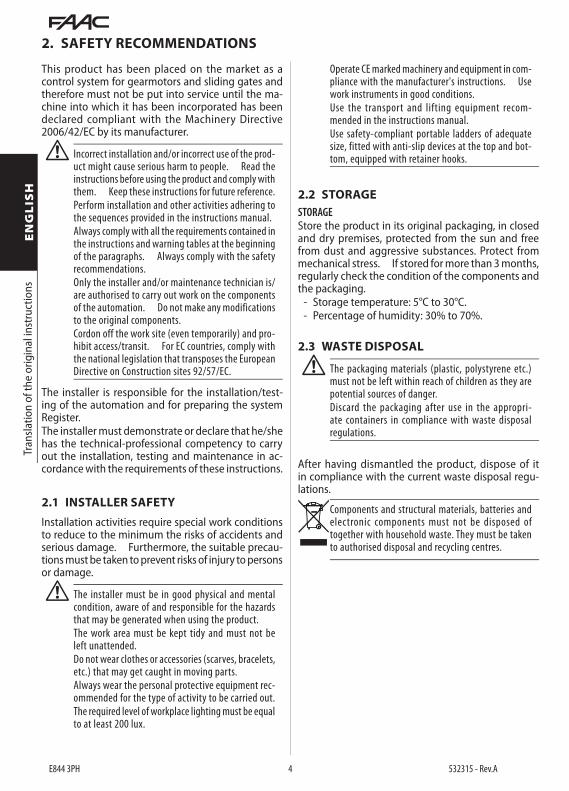
! The installer must be in good physical and mental condition, aware of and responsible for the hazards that may be generated when using the product.The work area must be kept tidy and must not be left unattended.Do not wear clothes or accessories (scarves, bracelets, etc.) that may get caught in moving parts.Always wear the personal protective equipment rec-ommended for the type of activity to be carried out.The required level of workplace lighting must be equal to at least 200 lux.
2.2 STORAGE
After having dismantled the product, dispose of it in compliance with the current waste disposal regu-lations.
Components and structural materials, batteries and electronic components must not be disposed of together with household waste. They must be taken to authorised disposal and recycling centres.
2. SAFETY RECOMMENDATIONS
This product has been placed on the market as a control system for gearmotors and sliding gates and therefore must not be put into service until the ma-chine into which it has been incorporated has been declared compliant with the Machinery Directive 2006/42/EC by its manufacturer.
! Incorrect installation and/or incorrect use of the prod-uct might cause serious harm to people. Read the instructions before using the product and comply with them. Keep these instructions for future reference.Perform installation and other activities adhering to the sequences provided in the instructions manual.Always comply with all the requirements contained in the instructions and warning tables at the beginning of the paragraphs. Always comply with the safety recommendations.Only the installer and/or maintenance technician is/are authorised to carry out work on the components of the automation. Do not make any modifications to the original components.Cordon off the work site (even temporarily) and pro-hibit access/transit. For EC countries, comply with the national legislation that transposes the European Directive on Construction sites 92/57/EC.
The installer is responsible for the installation/test-ing of the automation and for preparing the system Register.The installer must demonstrate or declare that he/she has the technical-professional competency to carry out the installation, testing and maintenance in ac-cordance with the requirements of these instructions.
2.1 INSTALLER SAFETY
Operate CE marked machinery and equipment in com-pliance with the manufacturer's instructions. Use work instruments in good conditions.Use the transport and lifting equipment recom-mended in the instructions manual.Use safety-compliant portable ladders of adequate size, fitted with anti-slip devices at the top and bot-tom, equipped with retainer hooks.
STORAGEStore the product in its original packaging, in closed and dry premises, protected from the sun and free from dust and aggressive substances. Protect from mechanical stress. If stored for more than 3 months, regularly check the condition of the components and the packaging.
- Storage temperature: 5°C to 30°C.- Percentage of humidity: 30% to 70%.
2.3 WASTE DISPOSAL
! The packaging materials (plastic, polystyrene etc.) must not be left within reach of children as they are potential sources of danger.Discard the packaging after use in the appropri-ate containers in compliance with waste disposal regulations.

E844 3PH 5 532315 - Rev.A
202073 V.x ww/yyyy
Tran
slatio
n of
the
orig
inal
inst
ruct
ions
ENGLIS
H
3. E844 3PH
3.1 INTENDED USEThe FAAC E844 3PH electronic board has been de-signed to control FAAC 844 R 3PH and 884 MC 3PH gearmotors for horizontal movement sliding gates intended for installation in areas that are accessible to people, the main purpose of which is to provide safe access for goods or vehicles accompanied or driven by people in industrial, commercial or residential settings.
! Any other use that is not expressly specified in these instructions is prohibited and could affect the integrity of the product and/or represent a source of danger.
3.2 LIMITATIONS OF USE- Using the product in any configuration other than
that intended by FAAC S.p.A.is prohibited. It is prohibited to modify any of the product’s com-ponents
3.3 UNAUTHORISED USE- Do not use on motors or devices that are intended
for purposes other than operating gates.- Uses other than the intended use are prohibited.- It is prohibited to install the E844 3PH on smoke
and/or fire doors.- It is prohibited to install the E844 3PH in environ-
ments in which there is a risk of explosion and/or fire: the presence of flammable gases or fumes is a serious safety hazard (the product is not 94/9/EC ATEX certified).
- It is prohibited to power the system with energy sources other than those specified.
- It is prohibited to integrate commercial systems and/or equipment other than those specified, or use them for purposes not envisaged and author-ised by the corresponding manufacturers.
- It is prohibited to use and/or install accessories which have not been specifically authorised by FAAC S.p.A.
- It is prohibited to use the E844 3PH in the presence of faults which could compromise safety.
- Do not allow water jets of any type or size to come into direct contact with the E844 3PH.
- Do not expose the E844 3PH to corrosive chemical or environmental agents.
3.4 PRODUCT IDENTIFICATION
4 Technical data E844 3PHPower supply voltage 380-415 V~ 3PH + N
50/60 HzMax power 3 WMax. motor power 1500 WMax. accessories load 24 V" 500 mA
Bus 2easy 500 mAMax. flashing light load 230 V~ 60 W maxAmbient operating temperature -20 °C to +55 °CStopping space with 844 R 3PH 8 cmStopping space with 884 MC 3PH 8 cm
week/year of production
identification code firmware version
3.5 TECHNICAL SPECIFICATIONSE844 3PH is an electronic board designed to control a single motor having a maximum power of 1.5 kW and a 400V three phase + Neutral power supply.Display The board functions are programmed via a LCD display and 3 buttons.Limit switch In order to operate correctly, the opening and closing limit switches of the gearmotor have to be connected to the E844 3PH board .End of travel slowdown The E844 3PH can adjust the slowdown points close to the open and closed posi-tions, in order to limit inertial forces and reduce the vibrations of the gate when it is stopping (only in combination with the 844 R 3PH).Bus 2easy It is possible to connect FAAC Bus 2easy devices (photocells and control devices) to the E844 3PH board.Encoder The E844 3PH is fitted with a sensor for read-ing the encoder disc in the 844 R 3PH gearmotors, via which it is able to detect the presence of an obstacle (only with board installed on the operator). The sensitivity of the obstacle detection system can be adjusted.

E844 3PH 6 532315 - Rev.A
Tran
slatio
n of
the
orig
inal
inst
ruct
ions
ENGLIS
H4. INSTALLATION REQUIREMENTS
5. INSTALLATION
RISKS
PERSONAL PROTECTIVE EQUIPMENT
F ALWAYS DISCONNECT THE POWER SUPPLY before working on the board.If the disconnect switch is not in view, apply a warning sign stating “WARNING - Maintenance in Progress”.Turn the power on only after having made all the electrical connections and carried out the preliminary start-up checks.
! The E844 board is fitted with a plastic cover that safe-guards against electrocution by contact with live parts of the circuit. The cover should never be removed.
5.1 TOOLS REQUIRED
! Use appropriate tools and equipment in working en-vironments which comply with applicable legislation.
4.1 ELECTRICAL SYSTEM
F Always shut off the power supply before performing any work. If the disconnect switch is not in view, apply a warning sign stating “WARNING - Mainte-nance in Progress”.
! The electrical system must comply with applicable legislation in the country of installation.Use components and materials with CE marking which are compliant with the Low Voltage Directive 2014/35/EU and EMC Directive 2014/30/EU.The power supply line for the automation must be fitted with a multi-pole circuit breaker, with a suitable tripping threshold, a contact opening distance of at least 3 mm and a breaking capacity that complies with current regulations.The power supply for the automation must be fitted with a 30 mA differential switch. The metal parts of the structure must be earthed.Check that the protective earthing system com-plies with applicable regulations in the country of installation.The electrical cables of the automation system must be of a size and insulation class that is compliant with current legislation and laid in appropriate rigid or flexible conduits, either above or below ground.Use separate conduits for the power supply and the 12-24 V control devices / accessories cables. Check buried cable plans to ensure that there are no other electrical cables in proximity to the planned digging/drilling locations to prevent the risk of electrocution.Check that there are no pipes in the vicinity as well.The external electronic board must be housed in an enclosure that has a minimum IP 44 protection rating and fitted with a lock or another type of device to pre-vent access by unauthorised persons. The enclosure must be located in an accessible and non-hazardous area and at least 30 cm from the ground. The cable outlets must face downwards.The conduit fittings and the cable glands must prevent the entry of moisture, insects and small animals.Protect extension connections using junction boxes with an IP 67 protection rating or higher.The overall length of the BUS cables must not exceed 100 m.It is recommended to install a flashing light in a visible position to indicate when it is moving. The control accessories must be positioned in areas that are always accessible and not dangerous for the user. It is recommended to position the control acces-sories within the field of view of the automation. This is mandatory in the case of hold-to-run controls.
The hold-to-run controls in the dead-man mode of operation, must comply with standard EN 60947-5-1.If an emergency stop button has been installed, it must be EN13850 compliant.Comply with the following heights from the ground:- control accessories = minimum 150 cm- emergency buttons = maximum 120 cmIf the manual controls are intended to be used by disabled or infirm persons, highlight them with suitable pictograms and make sure that these users are able to access them.

E844 3PH 7 532315 - Rev.A
RP/D
EC
MOT
OR
LAM
P
MAI
NS
2EASY
OPEN SX OPEN DX
LIMIT
SW
F-+OPEN BOPEN A
SAFE CL
CL -HOP-H
SAFE OP
STOP GND
GNDOUT 1OUT 2TEST OUT
+24V
N L1 U V WL2 L3
M3
LAM
PN
GN
D+2
4V
FCC
FCA
230V~60W max
1500 W max
12345678
910111213
400V~ 3PH + N
INPUT
1
F2 F1F3
SAFE CL SAFE OP
STOP
OP - H CL - H
OPEN A OPEN B
LCD
CN10
FF-+
FCC
CN9
CN11
CN8
JP1
BUS MON
FCACN1
CN5
BUS BUS
CN4 CN3CN6
CN2/CN12
Tran
slatio
n of
the
orig
inal
inst
ruct
ions
ENGLIS
H
KEY:CN1 Removable terminal board for the mains power supplyCN2 / CN12 Faston connectors for earth connectionCN3 Removable terminal board for connecting the motor
CN4 Removable terminal board for connecting the flash-ing light
CN5 Terminal board for connecting limit switchCN6 / CN11 Quick insertion connectors for inductive limit switch
CN8 Removable terminal board for outputs and accessories power supply
CN9 Removable terminal board for connecting control devices
CN10 Removable terminal board for connecting Bus 2easy devices
JP1 Connector (5 pin) for FAAC radio/decoder boardsLCD Programming displayF1 F2 F3 Mains power supply fuses (8AT)+ - F Programming buttons
Status LEDs :STOP Stop commandCL - H Priority close commandOP - H Priority open commandSAFE CL Closing safety deviceSAFE OP Opening safety deviceOPEN B Partial motion commandOPEN A Total motion commandFCA Opening limit switchFCC Closing limit switchBUS Bus 2easy devicesBUS MON Bus 2easy line
5.2 COMPONENTS
E844 3PH 8 532315 - Rev.A
Tran
slatio
n of
the
orig
inal
inst
ruct
ions
ENGLIS
H5.3 CONNECTIONS
CONTROL DEVICES
RP/D
EC
MOT
OR
LAM
P
MAI
NS
2EASY
OPEN SX OPEN DX
LIMIT
SW
F-+OPEN BOPEN A
SAFE CL
CL -HOP-H
SAFE OP
STOP GND
GNDOUT 1OUT 2TEST OUT
+24V
N L1 U V WL2 L3
M3
LAM
PN
GN
D+2
4V
FCC
FCA
230V~60W max
1500 W max
12345678
910111213
400V~ 3PH + N
INPUT
CN9
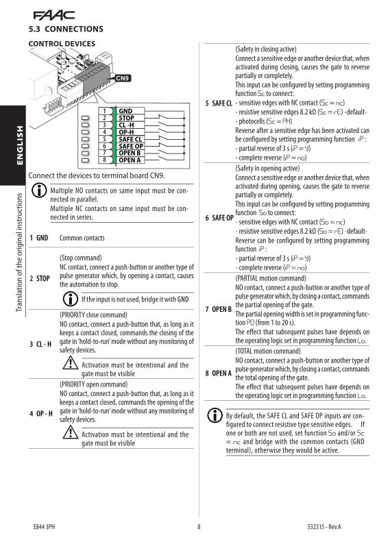
Connect the devices to terminal board CN9.
Multiple NO contacts on same input must be con-nected in parallel. Multiple NC contacts on same input must be con-nected in series.
1 GND Common contacts
2 STOP
(Stop command)NC contact, connect a push-button or another type of pulse generator which, by opening a contact, causes the automation to stop.
If the input is not used, bridge it with GND
3 CL - H
(PRIORITY close command)NO contact, connect a push-button that, as long as it keeps a contact closed, commands the closing of the gate in ‘hold-to-run’ mode without any monitoring of safety devices.
! Activation must be intentional and the gate must be visible
4 OP - H
(PRIORITY open command)NO contact, connect a push-button that, as long as it keeps a contact closed, commands the opening of the gate in ‘hold-to-run’ mode without any monitoring of safety devices.
! Activation must be intentional and the gate must be visible
5 SAFE CL
(Safety in closing active)Connect a sensitive edge or another device that, when activated during closing, causes the gate to reverse partially or completely.This input can be configured by setting programming function Sc to connect:- sensitive edges with NC contact (Sc = nc)- resistive sensitive edges 8.2 kΩ (Sc = rE) -default-- photocells (Sc = PH)Reverse after a sensitive edge has been activated can be configured by setting programming function iP :- partial reverse of 3 s (iP = Y)- complete reverse (iP = no)
6 SAFE OP
(Safety in opening active)Connect a sensitive edge or another device that, when activated during opening, causes the gate to reverse partially or completely.This input can be configured by setting programming function So to connect:- sensitive edges with NC contact (So = nc)- resistive sensitive edges 8.2 kΩ (So = rE) -default-Reverse can be configured by setting programming function iP :- partial reverse of 3 s (iP = Y)- complete reverse (iP = no)
7 OPEN B
(PARTIAL motion command)NO contact, connect a push-button or another type of pulse generator which, by closing a contact, commands the partial opening of the gate. The partial opening width is set in programming func-tion PO (from 1 to 20 s).The effect that subsequent pulses have depends on the operating logic set in programming function Lo.
8 OPEN A
(TOTAL motion command)NO contact, connect a push-button or another type of pulse generator which, by closing a contact, commands the total opening of the gate.The effect that subsequent pulses have depends on the operating logic set in programming function Lo.
By default, the SAFE CL and SAFE OP inputs are con-figured to connect resistive type sensitive edges. If one or both are not used, set function So and/or Sc= nc and bridge with the common contacts (GND terminal), otherwise they would be active.

E844 3PH 9 532315 - Rev.A
Tran
slatio
n of
the
orig
inal
inst
ruct
ions
ENGLIS
H
ACCESSORIES POWER SUPPLY
RP/D
EC
MOT
OR
LAM
P
MAI
NS
2EASY
OPEN SX OPEN DX
LIMIT
SWF-+
OPEN BOPEN A
SAFE CL
CL -HOP-H
SAFE OP
STOP GND
GNDOUT 1OUT 2TEST OUT
+24V
N L1 U V WL2 L3
M3
LAM
PN
GN
D+2
4V
FCC
FCA
230V~60W max
1500 W max
12345678
910111213
400V~ 3PH + N
INPUT
CN8
24 V"0.5 A max
The E844 3PH supplies 24 V" and is short-circuit protected with a maximum current of 0.5 A for con-nected accessories.
OUTPUTS
RP/D
EC
MOT
OR
LAM
P
MAI
NS
2EASY
OPEN SX OPEN DX
LIMIT
SW
F-+OPEN BOPEN A
SAFE CL
CL -HOP-H
SAFE OP
STOP GND
GNDOUT 1OUT 2TEST OUT
+24V
N L1 U V WL2 L3
M3
LAM
PN
GN
D+2
4V
FCC
FCA
230V~60W max
1500 W max
12345678
910111213
400V~ 3PH + N
INPUT
CN8 0.2 A max
The E844 3PH has two Open Collector outputs that are activated according to programming functionso1 and o2. OUT active OUT not active 0 V" open circuit
Do not exceed the maximum load of 0.2 A for each output.
FAILSAFE
CN8
RP/D
EC
MOT
OR
LAM
P
MAI
NS
2EASY
OPEN SX OPEN DX
LIMIT
SW
F-+OPEN BOPEN A
SAFE CL
CL -HOP-H
SAFE OP
STOP GND
GNDOUT 1OUT 2TEST OUT
+24V
N L1 U V WL2 L3
M3
LAM
PN
GN
D+2
4V
FCC
FCA
230V~60W max
1500 W max
12345678
910111213
400V~ 3PH + N
INPUT
Failsafe is a functional test that is carried out before a movement to check that the devices connected to the SAFE inputs are working correctly.If the test fails, the board prevents the automation from moving (error 05).To enable/disable the failsafe, see programming function FS .
LIMIT SWITCHES
CN6CN11
CN5
RP/D
EC
MOT
OR
LAM
P
MAI
NS
2EASY
OPEN SX OPEN DX
LIMIT
SW
F-+OPEN BOPEN A
SAFE CL
CL -HOP-H
SAFE OP
STOP GND
GNDOUT 1OUT 2TEST OUT
+24V
N L1 U V WL2 L3
M3
LAM
PN
GN
D+2
4V
FCC
FCA
230V~60W max
1500 W max
12345678
910111213
400V~ 3PH + N
INPUT
In order for to operate correctly, the E844 3PH board has to be connected to the opening and closing limit switches. For the 844 R 3PH inductive sensor, use the quick insertion connector CN6 (open towards the right) or CN11 (open towards the left). The opening direction is determined by looking at the gate from the side on which the gearmotor is installed.For the 884 MC 3PH sensor, use terminal board CN5:FCA (OPENING limit switch) NC contactFCC (CLOSING limit switch) NC contactGND Common contacts+24V Accessories power
FLASHING LIGHT
CN4
RP/D
EC
MOT
OR
LAM
P
MAI
NS
2EASY
OPEN SX OPEN DX
LIMIT
SW
F-+OPEN BOPEN A
SAFE CL
CL -HOP-H
SAFE OP
STOP GND
GNDOUT 1OUT 2TEST OUT
+24V
N L1 U V WL2 L3
M3
LAM
PN
GN
D+2
4V
FCC
FCA
230V~60W max
1500 W max
12345678
910111213
400V~ 3PH + N
INPUT
The flashing light indicates that the gate is moving and must be installed in a position that is visible from both sides of the gate.Connect the flashing light (230 V~, max 60 W model), to terminal board CN4.Pre-flashing of 3 s before movement can be enabled via programming function PF.

E844 3PH 10 532315 - Rev.A
Tran
slatio
n of
the
orig
inal
inst
ruct
ions
ENGLIS
HBUS 2EASY DEVICES
RP/D
EC
MOT
OR
LAM
P
MAI
NS
2EASY
OPEN SX OPEN DX
LIMIT
SW
F-+OPEN BOPEN A
SAFE CL
CL -HOP-H
SAFE OP
STOP GND
GNDOUT 1OUT 2TEST OUT
+24V
N L1 U V WL2 L3
M3
LAM
PN
GN
D+2
4V
FCC
FCA
230V~60W max
1500 W max
12345678
910111213
400V~ 3PH + N
INPUT
CN10
If no BUS 2easy devices are used, leave the terminals free.
For connecting and assigning addresses see § Accessories .Do not exceed the maximum load of 0.5 A.
RADIO RECEIVER/DECODER BOARD
JP1
The quick insertion connector JP1 is specifically for 5-pin FAAC radio or decoder boards.It is a polarised type of connector.
If a FAAC model RP receiver is used, it is recommended to install the appropriate external antenna in order to obtain a sufficient range.
MOTOR
CN3
RP/D
EC
MOT
OR
LAM
P
MAI
NS
2EASY
OPEN SX OPEN DX
LIMIT
SW
F-+OPEN BOPEN A
SAFE CL
CL -HOP-H
SAFE OP
STOP GND
GNDOUT 1OUT 2TEST OUT
+24V
N L1 U V WL2 L3
M3
LAM
PN
GN
D+2
4V
FCC
FCA
230V~60W max
1500 W max
12345678
910111213
400V~ 3PH + N
INPUT
Connect the three phase wires of the electric motor.
! The gearmotor MUST be connected to the earth of the electrical system.
CONNECTING THE EARTH
CN2 CN12
To connect the earth of the board to the earth plug on the gearmotor, insert the cable with the crimped faston connector into CN2 or CN12. The second faston connector can be used to connect the ground of the electrical system.
! The gearmotor MUST be connected to the earth of the electrical system.
MAINS POWER SUPPLY
F Carry out the following operations with the power supply disconnected.
F2F3 F1
CN1
RP/D
EC
MOT
OR
LAM
P
MAI
NS
2EASY
OPEN SX OPEN DX
LIMIT
SW
F-+OPEN BOPEN A
SAFE CL
CL -HOP-H
SAFE OP
STOP GND
GNDOUT 1OUT 2TEST OUT
+24V
N L1 U V WL2 L3
M3
LAM
PN
GN
D+2
4V
FCC
FCA
230V~60W max
1500 W max
12345678
910111213
400V~ 3PH + N
INPUT
Connect the 3 Phase wires (400 V~) and the Neutral of the mains power supply using cables having a minimum diameter of 2.5 mm.The board has an 8AT fuse for each phase.

E844 3PH 11 532315 - Rev.A
2
RP/D
EC
MOT
OR
LAM
P
MAI
NS
2EASY
OPEN SX OPEN DX
LIMIT
SW
F-+OPEN BOPEN A
SAFE CL
CL -HOP-H
SAFE OP
STOP GND
GNDOUT 1OUT 2TEST OUT
+24V
N L1 U V WL2 L3
M3
LAM
PN
GN
D+2
4V
FCC
FCA
230V~60W max
1500 W max
12345678
910111213
400V~ 3PH + N
INPUT
F- +
Tran
slatio
n of
the
orig
inal
inst
ruct
ions
ENGLIS
H
6. SET-UP
RISKS
PERSONAL PROTECTIVE EQUIPMENT
! During operation, there is a risk of fingers and hands being trapped between the rack, pinion and gearmotor.
Carry out the steps, referring to the relative sections for details.1. Turn on power to the board.2. Check the direction of rotation of the motor:
- release the gearmotor, move the gate manually to its half-travel position and then re-lock it
- activate the open command OP-H temporarily and make sure that the gate moves in the opening direc-tion
- if the gate moves in the closing direction, temporarily disconnect the power supply and invert two phases of the motor (on connector CN3)
3. Release the gearmotor, move the gate manually to its closed position and then re-lock it (make sure that the FCC led switches off in this position and that 00) appears on the display.
4. Set the type of gearmotor connected: function dF in programming.
5. Only for 844 R 3PH: program the pre-limit switch decelerations in function rP in programming. The pre-limit switch deceleration reduces the inertia of the gate, allowing the impact forces to fall within the limits indicated in the standard.
6. Carry out the learning procedure for any BUS 2easy devices: function bU in programming.
7. Set the functions So (safety in opening) and Sc (safety in closing) according to the type of devices connected.
8. Carry out the learning procedure for the work times (SETUP): function tL in programming.
In order for the SETUP procedure to be carried out, the CLOSED limit switch must be engaged by the gate.
9. If the board is installed on gearmotor 844 R 3PH, regulate the obstacle detection sensitivity: function EC in programming.
10. Complete the programming according to the required operating characteristics.
11. Make sure that the automation system is working properly with all the devices installed.
6.1 PROGRAMMING
■ Accessing the programming menu- Press and hold button F: the first function dF ap-
pears on the display. The function is displayed as long as the F button remains pressed.
- Release button F: the display shows the value of the function.
■ Modifying the settings- When the display indicates the value of the func-
tion, press the + or - button to modify it.- Press button F to go to the next function. The
function is displayed as long as button F remains pressed.
The changes are saved when you exit from program-ming mode.
■ Exiting programming mode- Scroll through the menu until you reach the St
function and release the button. The display reverts to the automation status view. Alternatively, press buttons F and - simultaneously at any time during programming.
E844 3PH 12 532315 - Rev.A
Tran
slatio
n of
the
orig
inal
inst
ruct
ions
ENGLIS
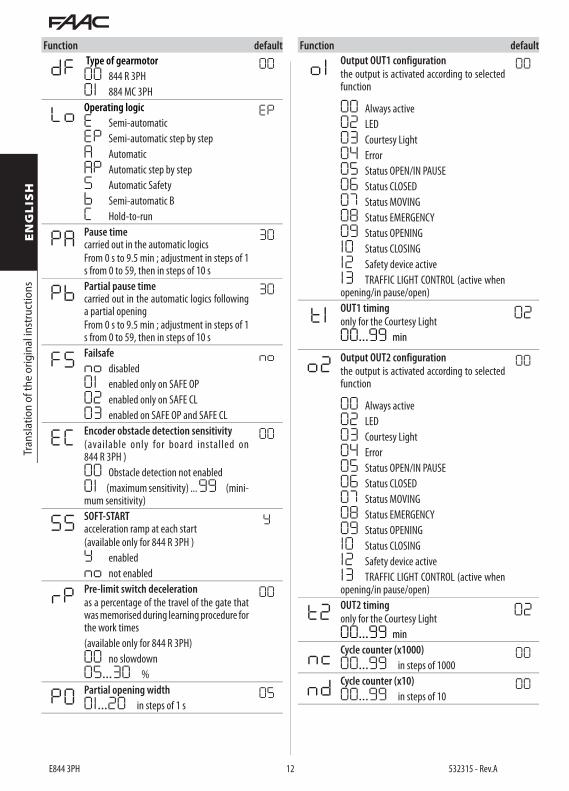
HFunction default
dF Type of gearmotor00 844 R 3PH01 884 MC 3PH
00
Lo Operating logicE Semi-automaticEP Semi-automatic step by stepA AutomaticAP Automatic step by stepS Automatic Safetyb Semi-automatic BC Hold-to-run
EP
PA Pause time carried out in the automatic logicsFrom 0 s to 9.5 min ; adjustment in steps of 1 s from 0 to 59, then in steps of 10 s
30
Pb Partial pause time carried out in the automatic logics following a partial openingFrom 0 s to 9.5 min ; adjustment in steps of 1 s from 0 to 59, then in steps of 10 s
30
FS Failsafe no disabled01 enabled only on SAFE OP02 enabled only on SAFE CL03 enabled on SAFE OP and SAFE CL
no
EC Encoder obstacle detection sensitivity (available only for board installed on 844 R 3PH )00 Obstacle detection not enabled01 (maximum sensitivity) ... 99 (mini-mum sensitivity)
00
SS SOFT-START acceleration ramp at each start(available only for 844 R 3PH )Y enabledno not enabled
Y
rP Pre-limit switch deceleration as a percentage of the travel of the gate that was memorised during learning procedure for the work times(available only for 844 R 3PH)00 no slowdown05...30 %
00
PO Partial opening width01.. .20 in steps of 1 s
05
Function default
o 1 Output OUT1 configurationthe output is activated according to selected function
00
00 Always active02 LED03 Courtesy Light04 Error05 Status OPEN/IN PAUSE06 Status CLOSED07 Status MOVING08 Status EMERGENCY09 Status OPENING10 Status CLOSING12 Safety device active13 TRAFFIC LIGHT CONTROL (active when opening/in pause/open)
t 1 OUT1 timingonly for the Courtesy Light00...99 min
02
o2 Output OUT2 configurationthe output is activated according to selected function
00
00 Always active02 LED03 Courtesy Light04 Error05 Status OPEN/IN PAUSE06 Status CLOSED07 Status MOVING08 Status EMERGENCY09 Status OPENING10 Status CLOSING12 Safety device active13 TRAFFIC LIGHT CONTROL (active when opening/in pause/open)
t2 OUT2 timingonly for the Courtesy Light00...99 min
02
nc Cycle counter (x1000)00...99 in steps of 1000
00
nd Cycle counter (x10)00...99 in steps of 10
00

E844 3PH 13 532315 - Rev.A
Tran
slatio
n of
the
orig
inal
inst
ruct
ions
ENGLIS
H
Function default
So SAFE OP input configurationnc Sensitive edge with NC contactrE Resistive sensitive edge 8.2 kΩ
rE
Sc SAFE CL input configurationnc Sensitive edge with NC contactrE Resistive sensitive edge 8.2 kΩPH Photocell with a NC contact
rE
i P Sensitive edge reverse modeY Partial reverse 3 sno Total reverse
Y
bu Learn BUS 2easy devicesSee the relative section
PF Pre-flashing for 3 s on the LAMP outputno No pre-flashingOC Pre-flashing before every movementCL Pre-flashing before closing
no
tL Learn work time (SETUP)In order for the learning procedure to be carried out, the CLOSED limit switch must be engaged by the gate.Press the + and - buttons simultaneously to start the learning function.If no button is pressed within 2 minutes, you automatically exit from programming mode.
St Exit from programming mode and display the status of the automation:
00 CLOSED01 OPEN03 STOPPED04 IN PAUSE05 OPENING06 CLOSING09 PRE-FLASHING and then OPENS10 PRE-FLASHING and then CLOSES
6.2 OPERATING LOGICSThe STOP command has priority over all other com-mands and stops the automation in all the logics.In all the logics, except B and C, the OPEN B command partially opens the gate if it is closed, in all other states it has the same function as the OPEN A command.In logics B and C (separate opening and closing com-mand logics), OPEN B only closes the gate.
■ A AUTOMATICThis logic only requires the OPEN command to be used.OPEN if the automation is closed, causes it to open. The automation closes automatically after the pause time has elapsed.OPEN during pause, resets the pause time.OPEN during opening, is ignored.OPEN during closing, causes it to reopen.If the closing photocells are triggered during the pause time, they reset the pause time.
■ AP AUTOMATIC STEP-BY-STEPThis logic only requires the OPEN command to be used.OPEN if the automation is closed, causes it to open. The automation closes automatically after the pause time has elapsed.OPEN during pause, stops it and the next OPENcommand closes it.OPEN during opening, stops it and the next OPENcommand closes it.OPEN during closing, causes it to reopen.If the closing photocells are triggered during the pause time, they reset the pause time.
■ S AUTOMATIC SAFETYThis logic only requires the OPEN command to be used.OPEN if the automation is closed, causes it to open. The automation closes automatically after the pause time has elapsed.OPEN during the pause, causes it to close.OPEN during opening, causes it to close.OPEN during closing, causes it to reopen.If the closing photocells are triggered during the pause time, they close the automation 3 seconds after they have been released.
■ E SEMI-AUTOMATICThis logic only requires the OPEN command to be used.OPEN if the automation is closed, causes it to open.OPEN if the automation is open, causes it to close.OPEN during opening, stops it and the next OPENcommand closes it.OPEN during closing, causes it to reopen.
E844 3PH 14 532315 - Rev.A
Tran
slatio
n of
the
orig
inal
inst
ruct
ions
ENGLIS
H■ EP SEMI-AUTOMATIC STEP-BY-STEPThis logic only requires the OPEN command to be used.OPEN if the automation is closed, causes it to open.OPEN if the automation is open, causes it to close.OPEN during opening or closing, stops it and the next OPEN command reverses the direction.
■ C HOLD- TO- RUNThis logic requires the maintained OPEN A (open) and OPEN B (close) commands to be used.
! In the Hold-to-run mode:- the control must be activated intentionally and the gate must be visible- the SAFE inputs stop the movement immediately
Maintained OPEN A opens the automation.Maintained OPEN B closes the automation.
■ b SEMI-AUTOMATIC bThis logic requires the OPEN A (open) and OPEN B (close) commands to be used.OPEN A if the automation is closed, causes it to open.OPEN A during opening, has no effect.OPEN A during closing, causes it to reopen.OPEN B if the automation is open, causes it to close.OPEN B during closing, has no effect.OPEN B during opening, causes it to close.Movement stops if the closing photocells are triggered.
6.3 SETUPThe SETUP must be carried out when the board is first installed, each time the board is replaced or installed in another system, or if the characteristics of the gate change.Set-up procedure:
- The gate MUST engage the CLOSED limit switch (make sure that the FCC LED is off ).
- Select the tl function in programming.- Press and hold down the + and - buttons simul-
taneously, the gate starts to open and S1 appears on the display.
- SETUP is complete when the open limit switch is reached.
6.4 RESTORE THE DEFAULT VALUESTo restore the default values for all the functions:
- Press and hold down the + , - , F buttons simultane-ously for 10 seconds
- Release the buttons when the separator point between the two digits on the display flashes
7. PUTTING INTO SERVICE
7.1 FINAL CHECKS1. Make sure that the forces generated by the gate
are within the limits permitted by the current regulations. Use an impact force tester in ac-cordance with EN 12453. For non-EU countries, of there are no specific local regulations, the force must be less than 150 N. If necessary, make any adjustments that may be needed by referring also
to the gearmotor instructions.2. Carry out a complete functional test of the automa-
tion and all the installed devices.3. Refer to the gearmotor instructions for any ad-
ditional tests that may be required.
7.2 CLOSE THE ENCLOSUREClose the enclosure in which the board is housed by referring to the specific instructions.
7.3 FINAL OPERATIONSMake sure that the system delivery requirements have been fulfilled (otherwise arrange for them) i.e. that they correspond to the board installed / replaced.
E844 3PH 15 532315 - Rev.A
12
543
12
12
543
12
12
543
12
SAFE CL
SAFE CL
GND
GND
GND
TEST OUT
+24V
+24V
+24V
+24V
+24V
+24V
TEST OUT
TEST OUT
Tran
slatio
n of
the
orig
inal
inst
ruct
ions
ENGLIS
H
8. ACCESSORIES
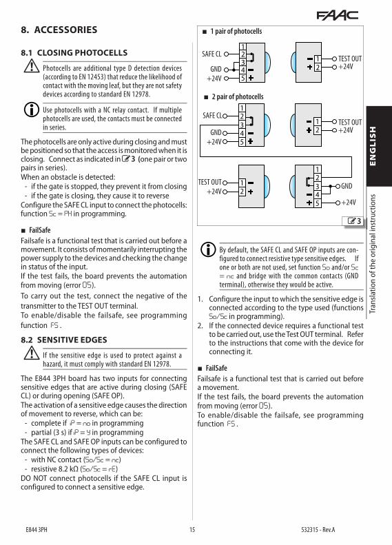
8.1 CLOSING PHOTOCELLS
! Photocells are additional type D detection devices (according to EN 12453) that reduce the likelihood of contact with the moving leaf, but they are not safety devices according to standard EN 12978.
Use photocells with a NC relay contact. If multiple photocells are used, the contacts must be connected in series.
The photocells are only active during closing and must be positioned so that the access is monitored when it is closing. Connect as indicated in 3(one pair or two pairs in series). When an obstacle is detected:
- if the gate is stopped, they prevent it from closing- if the gate is closing, they cause it to reverse
Configure the SAFE CL input to connect the photocells: function Sc = PH in programming.
■ FailSafeFailsafe is a functional test that is carried out before a movement. It consists of momentarily interrupting the power supply to the devices and checking the change in status of the input.If the test fails, the board prevents the automation from moving (error 05).To carry out the test, connect the negative of the transmitter to the TEST OUT terminal.To enable/disable the failsafe, see programming function FS .
8.2 SENSITIVE EDGES
! If the sensitive edge is used to protect against a hazard, it must comply with standard EN 12978.
The E844 3PH board has two inputs for connecting sensitive edges that are active during closing (SAFE CL) or during opening (SAFE OP).The activation of a sensitive edge causes the direction of movement to reverse, which can be:
- complete if iP = no in programming- partial (3 s) if iP = Y in programming
The SAFE CL and SAFE OP inputs can be configured to connect the following types of devices:
- with NC contact (So/Sc = nc)- resistive 8.2 kΩ (So/Sc = rE)
DO NOT connect photocells if the SAFE CL input is configured to connect a sensitive edge.
By default, the SAFE CL and SAFE OP inputs are con-figured to connect resistive type sensitive edges. If one or both are not used, set function So and/or Sc= nc and bridge with the common contacts (GND terminal), otherwise they would be active.
1. Configure the input to which the sensitive edge is connected according to the type used (functions So/Sc in programming).
2. If the connected device requires a functional test to be carried out, use the Test OUT terminal. Refer to the instructions that come with the device for connecting it.
■ FailSafeFailsafe is a functional test that is carried out before a movement.If the test fails, the board prevents the automation from moving (error 05).To enable/disable the failsafe, see programming function FS .
3
■ 1 pair of photocells
■ 2 pair of photocells
E844 3PH 16 532315 - Rev.A
2EASY
BUS2 Easy
BUS2 Easy
BUS2 Easy
CN10
4
Tran
slatio
n of
the
orig
inal
inst
ruct
ions
ENGLIS
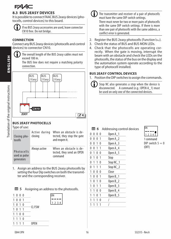
H8.3 BUS 2EASY DEVICESIt is possible to connect FAAC BUS 2easy devices (pho-tocells, control devices) to this board.
If no BUS 2easy accessories are used, leave connector CN10 free. Do not bridge.
CONNECTION Connect any BUS 2easy devices (photocells and control devices) to connector CN10.
The overall length of the BUS 2easy cables must not exceed 100 m.The BUS line does not require a matching polarity connection.
BUS 2EASY PHOTOCELLSType of use:
Closing pho-tocells
Ac t ive dur ing closing
When an obstacle is de-tected, they stop the gate and reopen it.
P h o t o c e l l s used as pulse generators
Always active When an obstacle is de-tected, they send an OPEN command
1. Assign an address to the BUS 2easy photocells by setting the four Dip switches on both the transmit-ter and the corresponding receiver.
5 Assigning an address to the photocells.
1 0 0 0
CL FSW
1 0 0 11 0 1 01 0 1 11 1 0 01 1 1 01 1 1 1 OPEN
ON
1 2 3 4
The transmitter and receiver of a pair of photocells must have the same DIP switch settings.There must never be two or more pairs of photocells with the same DIP switch settings. If there is more than one pair of photocells with the same address, a conflict error is generated.
2. Register the BUS 2easy photocells (Function bu).3. Check the status of BUS and BUS MON LEDs.4. Check that the photocells are operating cor-
rectly. When the gate is moving, interrupt the beam with an obstacle and check the LEDs on the photocells, the status of the bus on the display and the automation system operate according to the type of photocell installed.
BUS 2EASY CONTROL DEVICES1. Position the DIP switches to assign the commands.
Stop NC also generates a stop when the device is disconnected. A command (e.g.: OPEN A_1) must be used on only one of the connected devices.
6 Addressing control devices0 0 0 0 Open A_10 0 0 1 Open A_20 0 1 0 Open A_30 0 1 1 Open A_40 1 0 0 Open A_50 1 0 1 Stop0 1 1 0 Stop NC_10 1 1 1 Stop NC_21 0 0 0 Close1 0 0 1 Open B_11 0 1 0 Open B_21 0 1 1 Open B_31 1 0 0 Open B_41 1 0 1 Open B_51 1 1 0 / 1 1 1 1 /
ON
1 2 3 4 5
1 commandDIP switch 5 = 0 (OFF)

E844 3PH 17 532315 - Rev.A
RP/D
EC
MOT
OR
LAM
P
MAI
NS
2EASY
OPEN SX OPEN DX
LIMIT
SW
F-+OPEN BOPEN A
SAFE CL
CL -HOP-H
SAFE OP
STOP GND
GNDOUT 1OUT 2TEST OUT
+24V
N L1 U V WL2 L3
M3
LAM
PN
GN
D+2
4V
FCC
FCA
230V~60W max
1500 W max
12345678
910111213
400V~ 3PH + N
INPUT
BUS MON BUS
RP/D
EC
MOT
OR
LAM
P
MAI
NS
2EASY
OPEN SX OPEN DX
LIMIT
SW
F-+OPEN BOPEN A
SAFE CL
CL -HOP-H
SAFE OP
STOP GND
GNDOUT 1OUT 2TEST OUT
+24V
N L1 U V WL2 L3
M3
LAM
PN
GN
D+2
4V
FCC
FCA
230V~60W max
1500 W max
12345678
910111213
400V~ 3PH + N
INPUT
1 12RP
/DEC
MOT
OR
LAM
P
MAI
NS
2EASY
OPEN SX OPEN DX
LIMIT
SW
F-+OPEN BOPEN A
SAFE CL
CL -HOP-H
SAFE OP
STOP GND
GNDOUT 1OUT 2TEST OUT
+24V
N L1 U V WL2 L3
M3
LAM
PN
GN
D+2
4V
FCC
FCA
230V~60W max
1500 W max
12345678
910111213
400V~ 3PH + N
INPUT
211
3 104 9
7 146
RP/D
EC
MOT
OR
LAM
P
MAI
NS
2EASY
OPEN SX OPEN DX
LIMIT
SW
F-+OPEN BOPEN A
SAFE CL
CL -HOP-H
SAFE OP
STOP GND
GNDOUT 1OUT 2TEST OUT
+24V
N L1 U V WL2 L3
M3
LAM
PN
GN
D+2
4V
FCC
FCA
230V~60W max
1500 W max
12345678
910111213
400V~ 3PH + N
INPUT
5
8
13
5
Tran
slatio
n of
the
orig
inal
inst
ruct
ions
ENGLIS
H
0 0 0 0 Open A_1 Open B_10 0 0 1 Open A_1 Open B_20 0 1 0 Open A_1 Stop0 0 1 1 Open A_1 Close0 1 0 0 Open A_2 Open B_10 1 0 1 Open A_2 Open B_20 1 1 0 Open A_2 Stop0 1 1 1 Open A_2 Close1 0 0 0 Open A_3 Open B_31 0 0 1 Open A_3 Open B_41 0 1 0 Open A_3 StopNC_11 0 1 1 Open A_3 Close1 1 0 0 Open A_4 Open B_3
1 1 0 1 Open A_4 Open B_41 1 1 0 Open A_4 StopNC_21 1 1 1 Open A_4 Close
2. Register the BUS 2easy control devices (Function bu).
3. Check the status of BUS and BUS MON LEDs.4. Check that the devices are working properly. Use
the controls to move the gate. Check the LEDs on the devices, the status of the bus on the display and make sure that the automation system operates according to the type of device installed.
BUS 2EASY DEVICE REGISTRATIONRegistration is required:
- When the automation system is first started or after the board has been replaced.
- Following any changes (addition, replacement or removal) to the BUS 2easy devices.
Registration procedure:1. Select the bu function in programming. When
F is released, the display shows the status of the BUS 2easy devices.
2. Press and hold the + and - buttons simultane-ously for at least 5 seconds until Y appears. The registration is complete.
3. Release the + and - buttons. The display shows the status of the BUS 2easy devices.
4. Check the status of the LEDs on the display (5 ).
ON
1 2 3 4 5
2 commandsDIP switch 5 = 1 (ON)
BUS MON Led - BUS 2easy line
Line monitoring. LED always on
Line short-circuited Error on the devices
BUS Led - BUS 2easy devices
At least one device is engaged/active
No device is engaged/active
Registered device verification procedure:1. Select the bu function in programming. After
registering one or more devices, bu displays seg-ment 13 on.
2. Press and hold the + button and keep it pressed; the segments relative to the registered devices will come on. Each segment of the display cor-responds to a type of device:
1 Open A control device2 Open B control device3 Closing photocells4 Photocells for Open impulse5 Not used6 Close control device7 Not used8 Stop control device9 Not used10 Not used11 Not used12 Not used13 BUS 2easy status14 Not used
no No device registeredcc BUS 2easy line short-circuitedEr BUS 2easy line error
E844 3PH 18 532315 - Rev.A
Tran
slatio
n of
the
orig
inal
inst
ruct
ions
ENGLIS
H9. DIAGNOSTICS
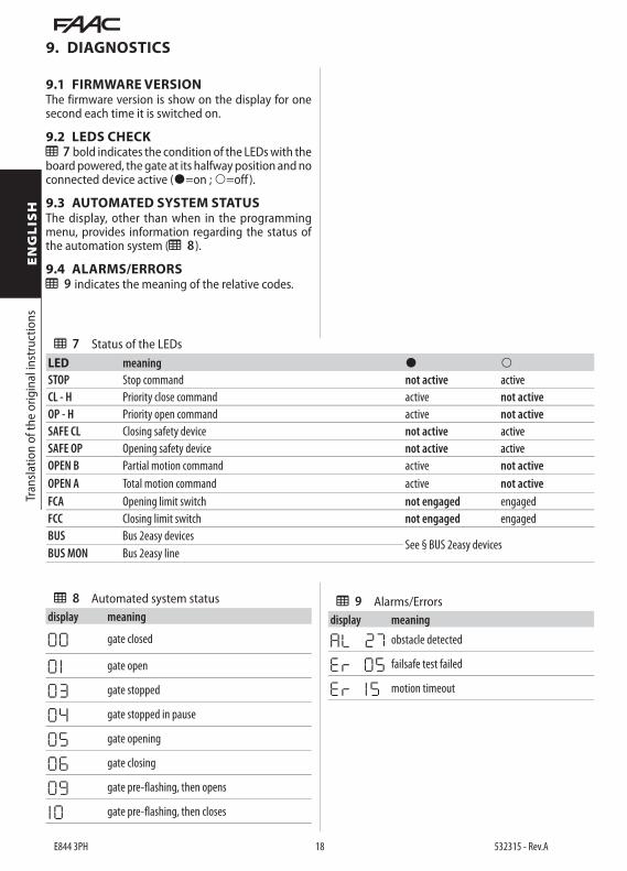
9.1 FIRMWARE VERSIONThe firmware version is show on the display for one second each time it is switched on.
9.2 LEDS CHECK7 bold indicates the condition of the LEDs with the board powered, the gate at its halfway position and no connected device active (=on ; =off ).
9.3 AUTOMATED SYSTEM STATUSThe display, other than when in the programming menu, provides information regarding the status of the automation system (8 ).
9.4 ALARMS/ERRORS9 indicates the meaning of the relative codes.
8 Automated system statusdisplay meaning
00 gate closed
0 1 gate open
03 gate stopped
04 gate stopped in pause
05 gate opening
06 gate closing
09 gate pre-flashing, then opens
1 0 gate pre-flashing, then closes
7 Status of the LEDsLED meaning STOP Stop command not active activeCL - H Priority close command active not activeOP - H Priority open command active not activeSAFE CL Closing safety device not active activeSAFE OP Opening safety device not active activeOPEN B Partial motion command active not activeOPEN A Total motion command active not activeFCA Opening limit switch not engaged engagedFCC Closing limit switch not engaged engagedBUS Bus 2easy devices
See § BUS 2easy devicesBUS MON Bus 2easy line
9 Alarms/Errorsdisplay meaning
AL 27 obstacle detected
Er 05 failsafe test failed
Er 15 motion timeout
E844 3PH 19 532315 - Rev.A
Tran
slatio
n of
the
orig
inal
inst
ruct
ions
ENGLIS
H
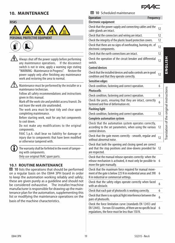
10 Scheduled maintenanceOperation FrequencyElectronic equipmentCheck that the power supply and connecting cables and the cable glands are intact. 12
Check that the connectors and wiring are intact. 12Check the integrity of the plastic board protection covers. 12Check that there are no signs of overheating, burning etc. of electronic components. 12
Check that the earth connections are intact. 12Check the operation of the circuit breaker and differential switch. 12
Control devicesCheck that the installed devices and radio controls are in good condition and that they operate correctly. 12
Sensitive edgesCheck condition, fastening and correct operation. 6PhotocellsCheck condition, fastening and correct operation. 6Check the posts, ensuring that they are intact, correctly fastened and free of deformation etc. 6
Flashing lightCheck condition, fastening and correct operation. 12Complete automation systemCheck that the automation system operates correctly, according to the set parameters, when using the various control devices.
12
Check that the gate moves correctly - smooth, regular and without abnormal noise. 12
Check that both the opening and closing speed are correct and that the stop positions and slow-downs provided for are respected.
12
Check that the manual release operates correctly: when the release mechanism is activated, it must only be possible to move the gate manually.
6
Check that the maximum force required for manual move-ment of the gate is below 225 N in residential areas and 390 N in industrial or commercial settings.
6
Check that the safety edges operate correctly when faced with an obstacle. 6
Check that each pair of photocells is working correctly. 6Check that there is no optical/light interference between the pairs of photocells. 6
Check the force limitation curve (standards EN 12453 and EN 12445). For non-EU countries, of there are no specific local regulations, the force must be less than 150 N.
6
10. MAINTENANCE
RISKS
PERSONAL PROTECTIVE EQUIPMENT
F Always shut off the power supply before performing any maintenance operations. If the disconnect switch is not in view, apply a warning sign stating “WARNING - Maintenance in Progress”. Restore the power supply only after finishing any maintenance work and restoring the area to normal.
! Maintenance must be performed by the installer or a maintenance technician.Follow all safety recommendations and instructions given in this manual.Mark off the work site and prohibit access/transit. Do not leave the work site unattended.The work area must be kept tidy and clear upon completing maintenance.Before starting work, wait for any hot components to cool down.Do not make any modifications to the original components.FAAC S.p.A. shall bear no liability for damage or injury due to components that have been modified or otherwise tampered with.
The warranty shall be forfeited in the event of tamper-ing with components.Only use original FAAC spare parts.
10.1 ROUTINE MAINTENANCE10 lists the operations that should be performed on a regular basis on the E844 3PH board in order to keep the automation working reliably and safely; these are given purely as a guideline and should not be considered exhaustive. The installer/machine manufacturer is responsible for drawing up the main-tenance plan for the automation, supplementing this list or modifying the maintenance operations on the basis of the machine characteristics.

FAAC S.p.A. Soc. UnipersonaleVia Calari, 10 - 40069 Zola Predosa BOLOGNA - ITALYTel. +39 051 61724 - Fax +39 051 09 57 820www.faac.it - www.faacgroup.com
E844 3PH 20 532315 - Rev.A