fs2x g1000 pilots guide
TRANSCRIPT

G1000 by Don Kuhn
Cessna Nav lll
Garmin G1000 Integrated Flight Deck
Pilots Guide Cessna Nav lll Garmin G1000 Integrated Flight Deck fs2x
1
Table of Contents G1000
SECTION 1. SYSTEM OVERVIEW 10
1.1 System Description.............................................................................................10
1.2 System Controls..................................................................................................13
1.3 G1000 Softkeys....................................................................................................17
1.3.1 PFD Softkeys............................................................................................17
1.3.1.1 Main PFD Softkey Panel.............................................................18
1.3.1.2 Inset Sublevel Softkey Panel.......................................................19
1.3.1.3 PFD Sublevel Softkey Panel........................................................20
1.3.1.4 XPDR Sublevel Softkey Panel.....................................................22
1.3.2 MFD Softkeys...........................................................................................23
1.3.2.1 Main MFD Softkey Panel............................................................23
1.3.2.2 Engine Sublevel Softkey Panel....................................................24
1.3.2.3 MAP Sublevel Softkey Panel.......................................................25
SECTION 2. NAVIGATION AND COMMUNICATIONS 27
2.1 NAV/COM Controls and Functions..................................................................28
2.1.1 Nav/Com Frequency Boxes.....................................................................28
2.1.2 Nav/Com Controls...................................................................................29
2.1.3 Nav/Com Instructions.............................................................................30
2.1.3.1 Change Nav/Com frequencies....................................................30
2.2 Frequency Auto Tuning......................................................................................29
2.2.1 Auto Tuning From the PFD...................................................................30
2.2.2 Auto Tuning From the MFD.........................................................30
2.3 Emergency Frequency 121.500 MHZ Tuning...................................................31
2.4 ADF Radio............................................................................................................32
2.4.1 ADF Controls and Functions..................................................................33
2
TABLE OF CONTENTS
Table of Contents G1000
2.4.2 ADF Instructions.....................................................................................33
2.4.2.1 Change Frequencies....................................................................33
2.5 Transponder Radio.............................................................................................34
2.5.1 XPDR controls and functions.................................................................35
2.5.2 XPDR Instructions..................................................................................35
2.5.2.1 Change Code................................................................................35
2.5.2.2 Change Mode...............................................................................36
2.5.2.3 Change Miscellaneous.................................................................36
SECTION 3. FLIGHT INSTRUMENTS 37
3.1 Attitude Indicator (AI) .......................................................................................37
3.1.1 AI Controls and Functions......................................................................38
3.2 AIRSPEED INDICATOR (ASI).........................................................................39
3.2.1 ASI Controls and Functions....................................................................40
3.2.2 ASI Instructions.......................................................................................41
3.3 ALTIMETER (ALT)...........................................................................................41
3.3.1 ALT Controls and Functions..................................................................42
3.3.2 Altimeter Instructions.............................................................................43
3.3.2.1 Change Reference Altitude.........................................................43
3.3.2.2 Change Barometric Pressure......................................................43
3.3.3 Altimeter Metric Display........................................................................44
3.3.3.1 Metric Instructions......................................................................44
3.4 Vertical Speed Indicator (VSI)...........................................................................45
3.4.1 VSI Controls and Functions....................................................................46
3.4.2 VSI Instructions......................................................................................47
3.5 Vertical Deviation/Glidepath/Glideslope Indicator (VDI)...............................47
3.5.1 VDI Controls and Functions...................................................................48
3.5.2 VDI Instructions.......................................................................................49
3.6 Horizontal Situation Indicator (HSI) ................................................................49
3.6.1 HSI Controls and Functions...................................................................50
3

Table of Contents G1000
3.6.2 HSI Instructions.......................................................................................53
3.6.2.1 Course Deviation Indicator (CDI )......................................................53
3.6.2.2 NAV Information Windows and Bearing Pointers............................54
3.7 Distance Measuring Equipment (DME)............................................................55
3.7.1 DME Controls and Functions.................................................................55
3.7.2 DME Instructions....................................................................................56
3.8 Marker Beacon Annunciation............................................................................57
3.9 Wind Data............................................................................................................58
3.9.1 Wind Data Controls and Functions.......................................................58
3.9.2 Wind Data Instructions...........................................................................59
3.10 Minimum Descent Altitude (MDA)..................................................................59
3.10.1 MDA Controls and Functions...............................................................60
3.10.2 MDA Instructions..................................................................................60
3.11 Generic Timer/Reference Speeds.....................................................................61
3.11.1 Timer Controls and Functions.............................................................62
3.11.2 Timer Instructions.................................................................................62
3.11.3 Reference Controls and Functions.......................................................63
3.11.4 Reference Instructions...........................................................................64
3.12 PFD Map Inset...................................................................................................65
3.12.1 Map Controls and Functions................................................................65
3.12.2 Map Instructions....................................................................................67
SECTION 4. ENGINE INDICATION SYSTEM (EIS) 68
4.1 EIS Engine Page..................................................................................................69
4.1.1 Engine page Controls and Functions.....................................................69
4.2 EIS Lean Page......................................................................................................72
4.2.1 Lean Page Controls and Functions........................................................72
4.2.2 Lean Page Instructions............................................................................74
4.3 EIS System Page...................................................................................................74
4
Table of Contents G1000
4.3.1 System Page Controls and Functions....................................................75
4.3.2 System Page Instructions…………………………………….….…......76
4.3.2.1 Reset Fuel Remaining and Fuel Used to Zero…………..…….76
4.3.2.2 Change Fuel Remaining Value…………………….………..…76
SECTION 5. MFD PAGE GROUPS 77
5.1 MFD Map Page Group……………………………………………………....…80
5.1.1 Navigation Map Page………………………………………………...…80
5.1.1.1 Map Setup……………………………………………………….81
5.1.1.1.1 Map Setup Map Group………................................…81
5.1.1.1.1.1 Map Group Page Instructions…………………85
5.1.1.1.2 Map Setup Weather Group…………………….….…86
5.1.1.1.3 Map setup traffic group………………………………86
5.1.1.1.3.1 Traffic Group Page Instructions………………87
5.1.1.1.4 Map Setup Aviation Group………………………..…88
5.1.1.1.4.1 Aviation Group Page Instructions…………..…90
5.1.1.1.5 Map Setup Airways Group………………….….....…91
5.1.1.1.5.1 Airways Group Page Instructions…………..…92
5.1.1.1.6 Map Setup Land Group………………………….…...…92
5.1.1.1.6.1 Land Group Page Instructions…………………….94
5.1.1.2 Declutter…………………………………………………….......95
5.1.1.2.1 Declutter Function Instructions…………………..…97
5.1.1.3 Measure Bearing/Distance…………………………………..…97
5.1.1.3.1 Measure Bearing/Distance Page Instructions……....99
5.1.2 Traffic Map Page………………………………………………….......100
5.1.2.1 Traffic Page Instructions…………………….……….…….....102
5.1.3 Terrain Proximity Map Page………………………………………....102
5
Table of Contents G1000
5.2 MFD Waypoint Page Group……………………………………………….…103
5.2.1 Airport Information Page…………………………………………….103
5.2.1.1 Airport Information Page Instructions………………………105
5.2.2 Intersection Information Page………………………………………..106
5.2.2.1 Intersection Information Page Instructions…………………108
5.2.3 NDB Information Page…………………………………………..……108
5.2.3.1 NDB Information Page Instructions…………………………110
5.2.4 VOR Information Page………………………………………….....…110
5.2.4.1 VOR Information page Instructions…………………………112
5.2.5 USRWPT Information Page…………………………………….……112
5.2.4.1 USRWPT Information page Instructions……………………114
5.3 MFD Auxiliary Page Group……………………………………………….....118
5.3.1 AUX Trip Planning Page…………………………………………..…118
5.3.1.1 Trip Stats………………………………………………………120
5.3.1.2 Fuel Stats……………………………………………………....121
5.3.1.3 Other Stats…………………………………………………..…121
5.3.1.4 Auxiliary Trip Planning Page Instructions…….……………122
5.3.2 AUX Utility Page………………………………………………………124
5.3.2.1 Auxiliary Utility Page Instructions…………………...………127
5.3.3 AUX GPS Status Page…………………………………….………..…128
5.3.4 AUX System Setup Page…………………………………………....…129
5.3.4.1 Auxiliary System Setup Page Instructions…………..………134
5.3.5 AUX Satellite Page…………………………………………….…........135
5.3.6 AUX System Status Page…………………………………..…….....…135
5.4 MFD Nearest Page Group………………………………………….……....…135
5.4.1 Nearest Airports Page……………………………………….……...…136
5.4.1.1 Nearest Airports Page Instructions……………….……..…...137
5.4.2 Nearest Intersections Page………………………………….……...…139
5.4.2.1 Nearest Intersections Page Instructions………….....……..…140
6

Table of Contents G1000
5.4.3 Nearest NDBs Page………………………….…………………...……141
5.4.3.1 Nearest NDBs Page Instructions………………….……......…142
5.4.4 Nearest VORs Page……………………….…………………….......…143
5.4.4.1 Nearest VORs Page Instructions………………………..……144
5.4.5 Nearest USRWPTs Page……………………….………………......…145
5.4.5.1 Nearest USRWPTs Page Instructions…………………..……146
5.4.6 Nearest Frequencies Page......................................................................147
5.4.6.1 Nearest Frequencies Page Instructions………………………148
5.4.7 Nearest Airspaces Page……………………….…….………...….…....149
5.4.7.1 Nearest Airspaces Page Instructions…………………………150
SECTION 6. DIRECT-TO (DTO) NAVIGATION PAGE 151
6.1 MFD DTO Navigation Page……………………….………………….....……151
6.1.1 MFD DTO Page Instructions…………………………………....……153
6.1 PFD DTO Navigation Page…………………………………………………...156
6.1.1 PFD DTO Page Instructions………….…………….……………...…157
SECTION 7. FLIGHT PLANNING (FPL) PAGE GROUP 161
7.1 MFD Flight Plan Page Group……………………….…………………..……162
7.1.1 MFD FPL active flight plan page……………………….……………163
7.1.1.1 FPL Entering and Editing from the Active FPL Page.………….166
7.1.1.2 MFD Active FPL Page Menu Window …………………………171
7.1.2 MFD FPL flight Plan Catalog Page……………………….…………176
7.1.2.1 Flight Plan Catalog Page Menu……….………………...……177
7.2 PFD Flight Plan Window..................................................................................181
7.2.1 PFD FPL Entering and Editing ..............................................................182
7.2.2 PFD Flight Plan Menu Window ..........................................................183
7
Table of Contents G1000
SECTION 8. PROCEDURE PAGE/WINDOW 187
8.1 MFD Procedures Page.......................................................................................192
8.1.1 MFD Procedures Page Instructions.....................................................190
8.2 MFD Airport Approach Page......................................................................................190
8.2.1 MFD Airport Approach Page Instructions……………….…………… 192
8.3 PFD Procedures Window..................................................................................198
8.3.1 PFD Procedures Window Instructions................................................199
8.4 Missed Approach……………………….……………………………………..199
SECTION 9. Vertical Navigation (VNV) 201
9.1 Vertical Navigation (VNV) Page……...……...……………….………...…...201
9.1.1 Flight Plan VNV Instructions……...………………………….…...…202
9.1.2 VNV DTO Page Instructions…………………………....…………….….207
SECTION 10. AUTOMATIC FLIGHT CONTROL SYSTEM (AFCS) 205
10.1 AFCS Controls and Functions........................................................................205
SECTION 11. AUDIO PANEL 202
11.1 Audio Panel Controls and Functions.............................................................202
SECTION 12. ALERTS 214
12.1 Alerts/Annunciations Window.......................................................................214
SECTION 13. PFD/MFD BACKLIGHTING 216
8

Table of Contents G1000
13.1 Backlighting Controls and Functions...........................................................216
13.2 Backlighting Instructions...............................................................................217
SECTION 14. MISCELLANEOUS 218
14.1 Map Range.......................................................................................................218
14.1.1 Map Range Instructions.............................................................218
14.2 Map Panning....................................................................................................219
14.2.1 Map Panning Instructions..........................................................219
14.3 Manual Electric Pitch Trim (MEPT).............................................................219
14.4 Lights Panel......................................................................................................221
14.5 Icons Group......................................................................................................222
9
Section 1. System Overview G1000 1. SYSTEM OVERVIEW 1.1 System Description The Garmin G1000 GPS Integrated Cockpit is revolutionizing the general aviation (GA) field. The older so-called
“steam gauge” panels are making way for the newer GPS-based “glass” panels. The G1000 displays a wealth of
flight information, including the information displayed on the older panels. This information is typically displayed
with sharp graphics on 2 large (10.4” diagonal) color, flat panel display screens. The units are connected via a
single high-speed Ethernet bus for fast exchange of information and data.
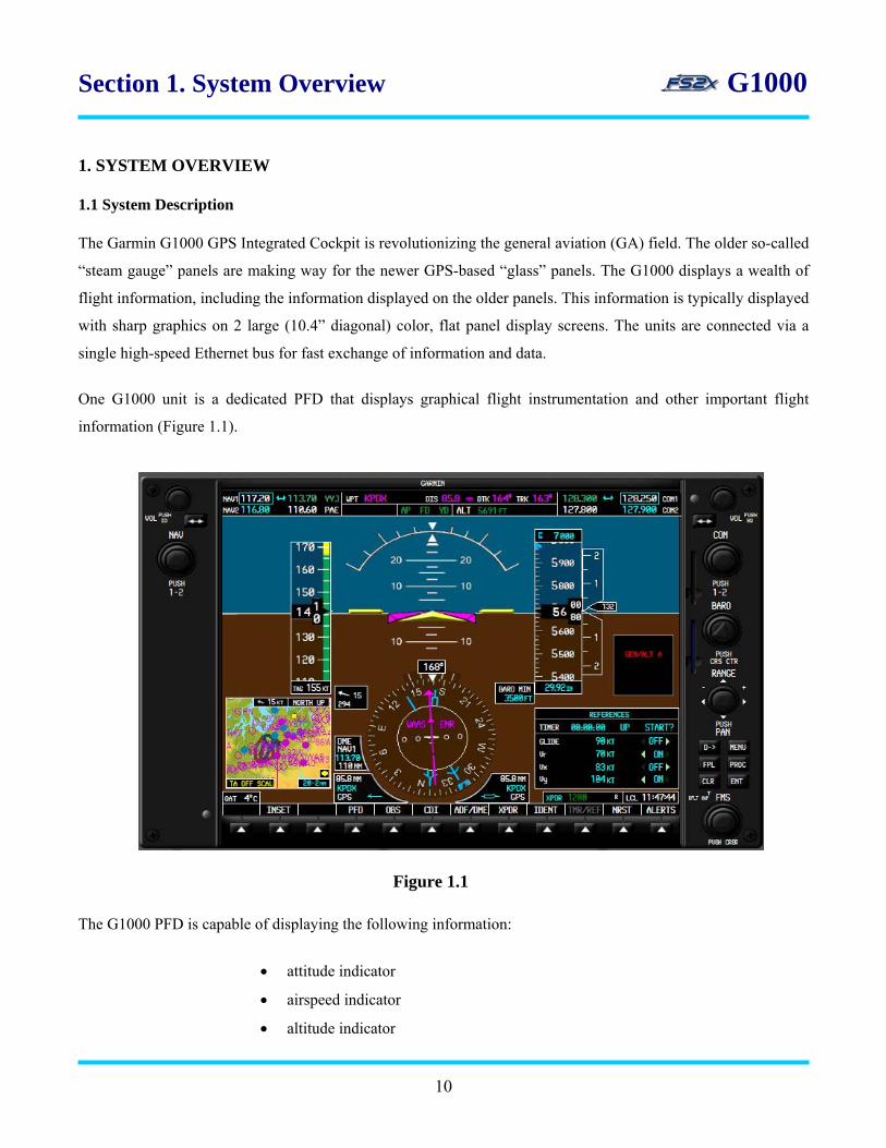
One G1000 unit is a dedicated PFD that displays graphical flight instrumentation and other important flight
information (Figure 1.1).
The G1000 PFD is capable of displaying the following information:
• attitude indicator
• airspeed indicator
• altitude indicator
Figure 1.1
10

Section 1. System Overview G1000
• horizontal situation indicator
• vertical speed indicator
• heading bug and digital read-out
• turn rate indicator
• slip/skid indicator
• navigation status bar
• navigation frequency window
• communication frequency window
• radio tuning window (ADF/DME)
• bearing pointers
• DME information window
• BRG1 Information window
• BRG2 Information window
• marker beacon receiver annunciations
• vertical deviation/glideslope indicator
• barometric setting box
• altitude reference box
• true airspeed box
• system time box
• outside air temperature box
• transponder status bar
• wind information
• inset map
• alerts window
• annunciations window
• Direct-to window
• flight plan window
• procedures window
• timer/reference window
• nearest airports window
• softkey annunciations
11

Section 1. System Overview G1000
The other G1000 unit is a dedicated MFD that presents a full-color moving map with navigational information,
and a display of numerous engine parameters (Figure 1.2).
Figure 14 5
Figure 1.2
The G1000 MFD is capable of displaying the following information:
• digital engine parameter readout (Engine Indication System; Section 4. EIS)
• flap and elevator trim indicator
• range adjustable, moving map
• map range rings
• topography information
• terrain information
• map setup window
• bearing/distance window
• direct-To window
• flight plan window
• procedures window
12

• traffic page
Section 1. System Overview G1000
• waypoint airport, intersection, NDB, and VOR information pages
• trip planning page
• system setup page
• nearest airport, intersection, NDB, and VOR pages
• page group box
• map orientation box
• wind information box
• map range box
• airspace alerts
• VNAV window
• user waypoint page
• navigation status bar
• navigation frequency window
• communication frequency window
• softkey annunciations
The G1000 MFD has too much information to be displayed at the same time; so much of the information is
contained on different pages and windows. There are 4 page groups displayed on the MFD.
• map group
• waypoint group
• auxiliary group
• nearest group
Each of these page groups contains sub-pages for a total of 20 pages. See Table 5.1 in Section 5. MFD Page
Groups for a list of the sub-pages.
1.2 System Controls Access to the PFD and MFD pages or windows is accomplished using numerous knobs and keys located around
the display bezel. The G1000 was designed so controls could be used with one hand, allowing the other hand to
fly the aircraft. The G1000 controls were also designed to simplify operation of the system and to minimize the
13
workload. The G1000 controls are located in the same place on the PFD and MFD bezels, and except where noted
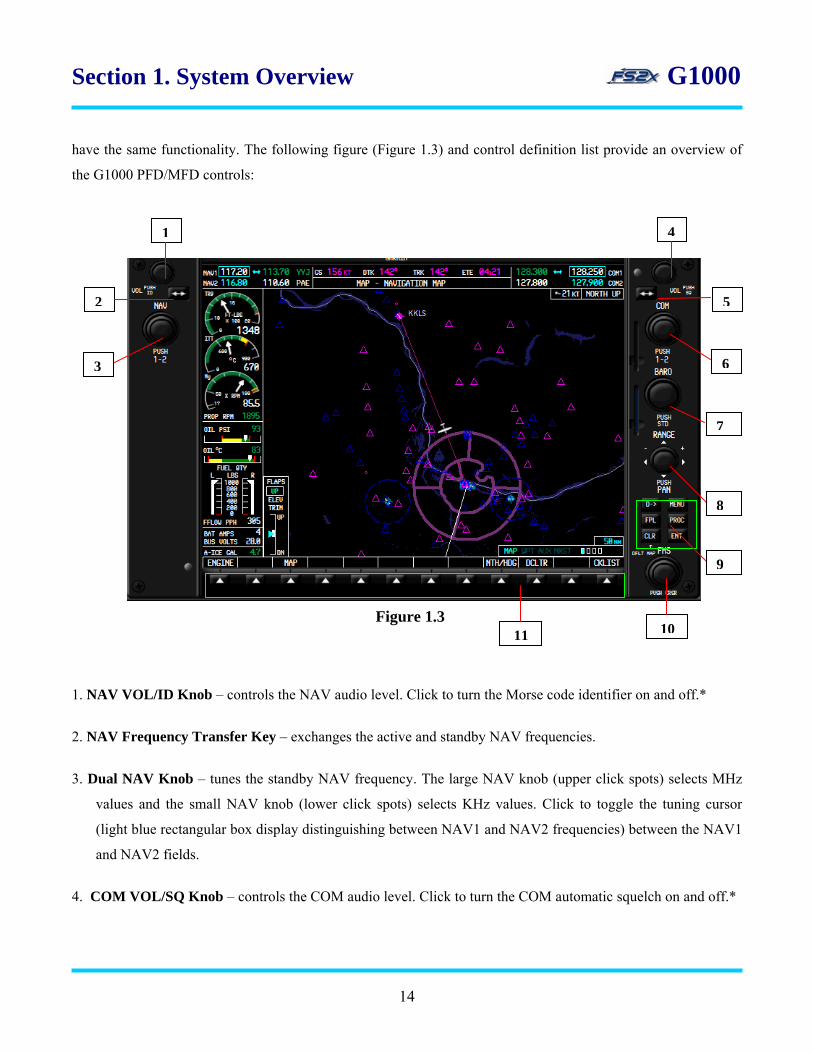
Section 1. System Overview G1000 have the same functionality. The following figure (Figure 1.3) and control definition list provide an overview of
the G1000 PFD/MFD controls:
5
6
7
41
2
3
8
9
Figure 1.3 11 10
1. NAV VOL/ID Knob – controls the NAV audio level. Click to turn the Morse code identifier on and off.*
2. NAV Frequency Transfer Key – exchanges the active and standby NAV frequencies.
3. Dual NAV Knob – tunes the standby NAV frequency. The large NAV knob (upper click spots) selects MHz
values and the small NAV knob (lower click spots) selects KHz values. Click to toggle the tuning cursor
(light blue rectangular box display distinguishing between NAV1 and NAV2 frequencies) between the NAV1
and NAV2 fields.
4. COM VOL/SQ Knob – controls the COM audio level. Click to turn the COM automatic squelch on and off.*
14

Section 1. System Overview G1000
5. COM Frequency Transfer Key – exchanges the active and standby COM frequencies. Holding the key down
for more than 2 seconds automatically tunes the emergency frequency 121.5 MHz into the active COM
frequency field.
6. Dual COM Knob – tunes the standby COM frequency. The large COM knob (upper click spots) selects MHz
values and the small COM knob (lower click spots) selects KHz values. Click to toggle the tuning cursor
(light blue rectangular box display distinguishing between COM1 and COM2 frequencies) between the
COM1 and COM2 fields.
7. BARO Knob – used to select the barometric pressure displayed in the barometric box of the PFD. Click on the
knob to set the barometric pressure to the standard sea level value (29.92/10.15).
8. Range Knob – changes the map display zoom factor. The PFD Range Knob only changes the PFD inset map,
and the MFD Range Knob changes only the MFD maps.
9. Flight Panel – flight panel keys (Figure 1.4) description and functioning are as follows:
9.1 Direct-To Key – opens the Direct-to window whereby the user enters a destination waypoint and
establishes a direct course to that destination waypoint. The HSI mode must be set to GPS, and the
autopilot NAV mode set to active to perform Direct-To navigation.
9.2 MENU Key – provides access to additional information and user selectable functions, specific to the
group page that is open when clicked. Opens a window for access.
9.3 FPL Key – opens the active flight plan page group where the user can create, delete, and edit flight
plans.
Figure 1.4
3
5
1
4
6
A
15
Section 1. System Overview G1000
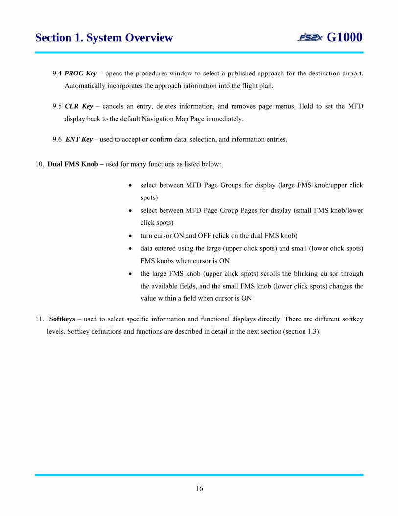
9.4 PROC Key – opens the procedures window to select a published approach for the destination airport.
Automatically incorporates the approach information into the flight plan.
9.5 CLR Key – cancels an entry, deletes information, and removes page menus. Hold to set the MFD
display back to the default Navigation Map Page immediately.
9.6 ENT Key – used to accept or confirm data, selection, and information entries.
10. Dual FMS Knob – used for many functions as listed below:
• select between MFD Page Groups for display (large FMS knob/upper click
spots)
• select between MFD Page Group Pages for display (small FMS knob/lower
click spots)
• turn cursor ON and OFF (click on the dual FMS knob)
• data entered using the large (upper click spots) and small (lower click spots)
FMS knobs when cursor is ON
• the large FMS knob (upper click spots) scrolls the blinking cursor through
the available fields, and the small FMS knob (lower click spots) changes the
value within a field when cursor is ON
11. Softkeys – used to select specific information and functional displays directly. There are different softkey
levels. Softkey definitions and functions are described in detail in the next section (section 1.3).
16
Section 1. System Overview G1000
1.3 G1000 Softkeys
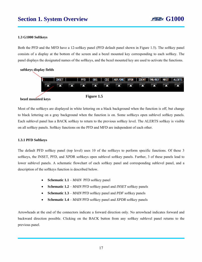
Both the PFD and the MFD have a 12-softkey panel (PFD default panel shown in Figure 1.5). The softkey panel
consists of a display at the bottom of the screen and a bezel mounted key corresponding to each softkey. The
panel displays the designated names of the softkeys, and the bezel mounted key are used to activate the functions.
bezel mounted keys
softkeys display fields
Figure 1.5
Most of the softkeys are displayed in white lettering on a black background when the function is off, but change
to black lettering on a gray background when the function is on. Some softkeys open sublevel softkey panels.
Each sublevel panel has a BACK softkey to return to the previous softkey level. The ALERTS softkey is visible
on all softkey panels. Softkey functions on the PFD and MFD are independent of each other.
1.3.1 PFD Softkeys
The default PFD softkey panel (top level) uses 10 of the softkeys to perform specific functions. Of these 3
softkeys, the INSET, PFD, and XPDR softkeys open sublevel softkey panels. Further, 3 of these panels lead to
lower sublevel panels. A schematic flowchart of each softkey panel and corresponding sublevel panel, and a
description of the softkeys function is described below.
• Schematic 1.1 – MAIN PFD softkey panel
• Schematic 1.2 – MAIN PFD softkey panel and INSET softkey panels
• Schematic 1.3 – MAIN PFD softkey panel and PDF softkey panels
• Schematic 1.4 – MAIN PFD softkey panel and XPDR softkey panels
Arrowheads at the end of the connectors indicate a forward direction only. No arrowhead indicates forward and
backward direction possible. Clicking on the BACK button from any softkey sublevel panel returns to the
previous panel.
17

Section 1. System Overview G1000 1.3.1.1 Main PFD softkey panel (Schematic 1.1)
OBSINSET ALERTS NRST TMR/REF XPDR IDENTADF/DMECDI PDF Schematic 1.1
1. Inset Key - opens the PFD inset map display. Also opens the inset sublevel softkey panel and leads to the
opening of additional sublevel softkey panels (see Schematic 1.2).
2. PDF Key - opens the PDF sublevel softkey panel and leads to the opening of additional sublevel softkey
panels (see Schematic 1.3).
3. OBS Key - selects the OBS mode when navigating an active leg by GPS.
4. CDI Key - cycles through GPS, VOR1, and VOR2 navigation modes on the CDI (see Schematic 1.4).
VOR1(onHSI)
VOR2(onHSI)
GPS(onHSI)
OBSINSET ALERTS NRSTTMR/REF XPDR IDENTADF/DMECDI PDF
5. ADF/DME Key - displays the ADF/DME tuning window.
6. XPDR Key - opens the transponder sublevel softkey panel and allows the user to select a transponder mode
and the transponder code (see Schematic 1.5).
7. IDENT KEY - activates a special identification pulse for 18 seconds to identify the transponder return on the
ATC screen.
8. TMR/REF Key - displays the timer/reference window.
9. NRST Key - displays the nearest airports window.
10. ALERTS Key - closes the annunciations window.
18
Section 1. System Overview G1000
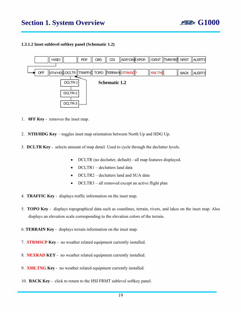
1.3.1.2 Inset sublevel softkey panel (Schematic 1.2)
PDF CDI ADF/DME IDENTXPDR NRST TMR/REF ALERTSINSET OBS
TRAFFIC TERRAIN STRMSCP XMLTNG TOPO OFF DCLTR BACK ALERTS
Schematic 1.2
DCLTR-1
DCLTR-2
DCLTR-3
NTH/HDG
1. 0FF Key - removes the inset map.
2. NTH/HDG Key - toggles inset map orientation between North Up and HDG Up.
3. DCLTR Key - selects amount of map detail. Used to cycle through the declutter levels.
• DCLTR (no declutter, default) - all map features displayed.
• DCLTR1 – declutters land data
• DCLTR2 – declutters land and SUA data
• DCLTR3 – all removed except an active flight plan
4. TRAFFIC Key - displays traffic information on the inset map.
5. TOPO Key - displays topographical data such as coastlines, terrain, rivers, and lakes on the inset map. Also
displays an elevation scale corresponding to the elevation colors of the terrain.
6. TERRAIN Key - displays terrain information on the inset map.
7. STRMSCP Key - no weather related equipment currently installed.
8. NEXRAD KEY - no weather related equipment currently installed.
9. XMLTNG Key - no weather related equipment currently installed.
10. BACK Key - click to return to the HSI FRMT sublevel softkey panel.
19
Section 1. System Overview G1000 11. ALERTS Key - closes the annunciations window.
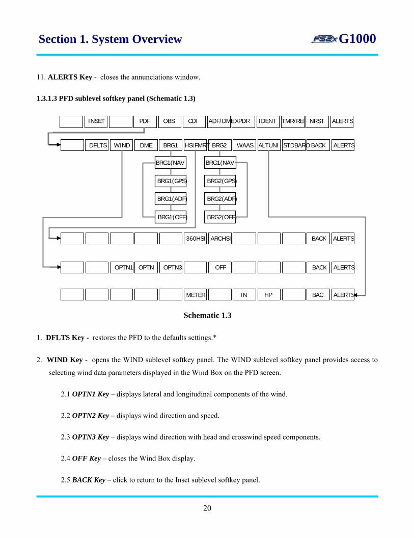
1.3.1.3 PFD sublevel softkey panel (Schematic 1.3)
INSET PDF CDI ADF/DMEXPDR IDENT NRST TMR/REF ALERTS OBS
DFLTS WIND DME
1. DFLTS Key - restores the PFD to the defaults settings.*
2. WIND Key - opens the WIND sublevel softkey panel. The WIND sublevel softkey panel provides access to
selecting wind data parameters displayed in the Wind Box on the PFD screen.
2.1 OPTN1 Key – displays lateral and longitudinal components of the wind.
2.2 OPTN2 Key – displays wind direction and speed.
2.3 OPTN3 Key – displays wind direction with head and crosswind speed components.
2.4 OFF Key – closes the Wind Box display.
2.5 BACK Key – click to return to the Inset sublevel softkey panel.
BRG1 HSIFMRT ALTUNIBRG2 BACK STDBARO ALERTS
BRG1(NAV
BRG1(NAV
BRG1(GPS)
BRG1(ADF)
BRG1(OFF)
BRG2(GPS)
BRG2(ADF)
BRG2(OFF)
WAAS
360HSI ARCHSI BACK ALERTS
HPINMETER
OFFOPTN3OPTNOPTN1
BAC
ALERTSBACK
ALERTS
Schematic 1.3
20

Section 1. System Overview G1000
2.6 ALERTS Key – closes the annunciations window.
3. DME Key - displays the DME information window.
4. BRG1 Key - cycles the Bearing 1 information window through NAV1, GPS, and ADF displays.
5. HSI FRMT Key - opens the HSI Formatting sublevel softkey panel.
5.1 360 HSI Key – displays HSI in a 360 degree view.
5.2 ARC HSI Key – displays HSI in an ARC view.
5.3 BACK Key – click to return to the HSI FRMT sublevel softkey panel.
5.4 ALERTS Key – closes the annunciations window.
6. BRG2 Key - cycles the Bearing 2 information window through NAV2, GPS, and ADF displays
7. WAAS KEY - turns WAAS navigation mode on/off and displays the WAAS navigation window.
8. ALT UNIT KEY - activates a special identification pulse for 18 seconds to identify the transponder return on
the ATC screen.
8.1 METERS Key – select/deselect to display the Selected Altitude in meters/feet (default).
8.2 IN Key – select to display barometric pressure in inches of mercury (default).
8.3 HPA Key – select to display barometric pressure in hectoPascals.
8.4 BACK Key – click to return to the altitude units sublevel softkey panel.
8.5 ALERTS Key – closes the annunciations window.
9. STD BARO Key - set barometric value directly to standard 29.92 inches of mercury (1013 hectoPascals)
10. BACK Key - click to return to the Inset sublevel softkey panel.
11. ALERTS Key - closes the annunciations window.
21
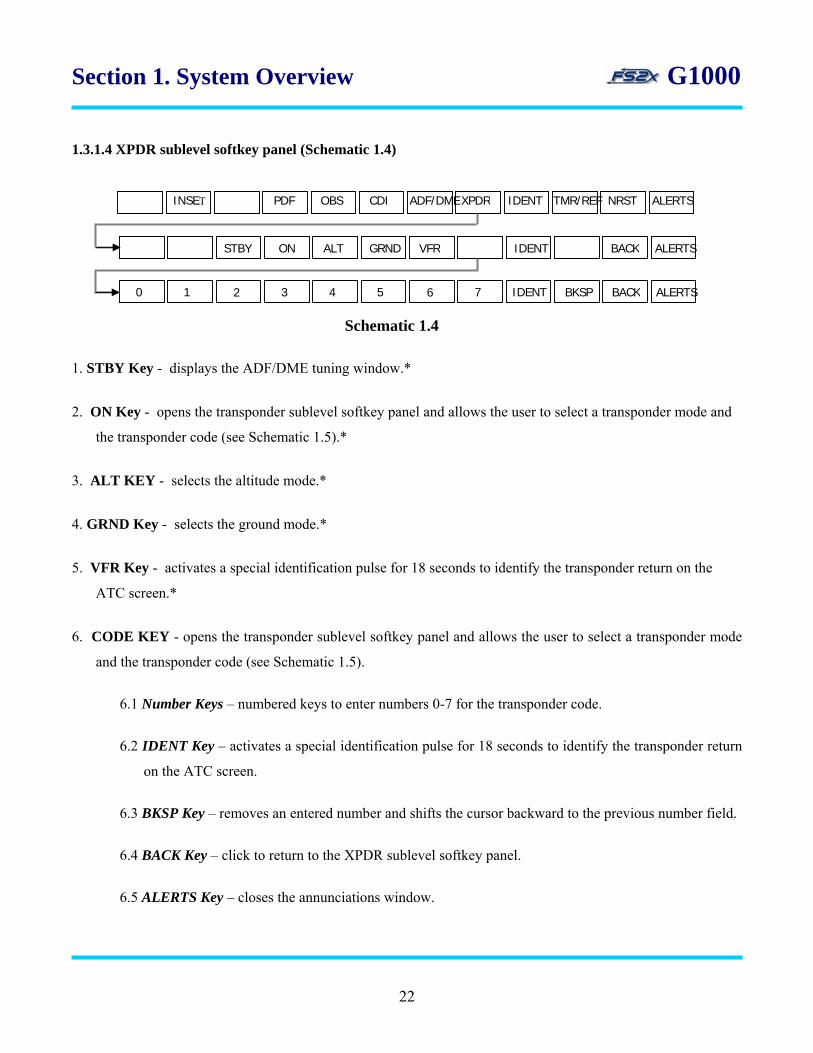
Section 1. System Overview G1000 1.3.1.4 XPDR sublevel softkey panel (Schematic 1.4)
ALERTS BACK IDENT BKSP 765 4 3 2 1 0
ALERTS BACK IDENT ON VFRGRND ALT STBY
OBSINSET ALERTS NRST TMR/REF XPDR IDENTADF/DMECDI PDF
1. STBY Key - displays the ADF/DME tuning window.*
2. ON Key - opens the transponder sublevel softkey panel and allows the user to select a transponder mode and
the transponder code (see Schematic 1.5).*
3. ALT KEY - selects the altitude mode.*
4. GRND Key - selects the ground mode.*
5. VFR Key - activates a special identification pulse for 18 seconds to identify the transponder return on the
ATC screen.*
6. CODE KEY - opens the transponder sublevel softkey panel and allows the user to select a transponder mode
and the transponder code (see Schematic 1.5).
6.1 Number Keys – numbered keys to enter numbers 0-7 for the transponder code.
6.2 IDENT Key – activates a special identification pulse for 18 seconds to identify the transponder return
on the ATC screen.
6.3 BKSP Key – removes an entered number and shifts the cursor backward to the previous number field.
6.4 BACK Key – click to return to the XPDR sublevel softkey panel.
6.5 ALERTS Key – closes the annunciations window.
Schematic 1.4
22

Section 1. System Overview G1000
1.3.1 MFD Softkeys
The default MFD softkey panel (top level) uses 4 of the softkeys to perform specific functions. Of these, 2
softkeys, the ENGINE and MAP softkeys open sublevel softkey panels. These panels lead to additional lower
sublevel panels. A schematic flowchart of each softkey panel and corresponding sublevel panel, and a description
of the softkeys function is described below.
• Schematic 1.5 – MAIN MFD softkey panel
• Schematic 1.6 – MAIN MFD softkey panel and ENGINE softkey panels
• Schematic 1.7 – MAIN MFD softkey panel and MAP softkey panels
Arrowheads at the end of the connectors indicate a forward direction only. No arrowhead indicates forward and
backward direction possible. Clicking on the BACK button from any softkey sublevel panel returns to the
previous panel.
1.3.2.1 Main MFD softkey panel (Schematic 1.5)
NTH/HDGENGIN DCLTR MAP CHKLST
Schematic 1.5
1. ENGINE Key - opens the Engine sublevel softkey panel (see Schematic 1.6).
2. MAP Key - opens the MAP sublevel softkey panel (see Schematic 1.7).
3. NTH/HDG Key - toggles inset map orientation between North Up and HDG Up.
4. DCLTR Key - selects the amount of MFD map detail. Used to cycle through the declutter levels.
• DCLTR (no declutter, default) - all map features displayed.
• DCLTR1 – declutters land data
• DCLTR2 – declutters land and SUA data
• DCLTR3 – all removed except an active flight plan
5. CHKLST Key - opens the kneeboard drop-down window where the user has access to the default checklist.
23
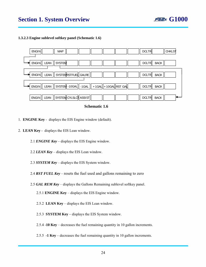
Section 1. System Overview G1000 1.3.2.3 Engine sublevel softkey panel (Schematic 1.6)
LEAN BACK ENGIN SYSTEM
ENGIN
LEAN BACK ENGIN SYSTEM
LEAN SYSTEM RSTFUEL GALRE BACK
-10GAL -1GAL +1GAL +10GAL
LEAN BACK ENGIN
DCLTR
SYSTEM CYLSLCT ASSIST
RST GAL
DCLTR
DCLTR
DCLTR
ENGIN CHKLSTDCLTR MAP
Schematic 1.6
1. ENGINE Key - displays the EIS Engine window (default).
2. LEAN Key - displays the EIS Lean window.
2.1 ENGINE Key – displays the EIS Engine window.
2.2 LEAN Key – displays the EIS Lean window.
2.3 SYSTEM Key – displays the EIS System window.
2.4 RST FUEL Key – resets the fuel used and gallons remaining to zero
2.5 GAL REM Key – displays the Gallons Remaining sublevel softkey panel.
2.5.1 ENGINE Key – displays the EIS Engine window.
2.5.2 LEAN Key – displays the EIS Lean window.
2.5.3 SYSTEM Key – displays the EIS System window.
2.5.4 -10 Key – decreases the fuel remaining quantity in 10 gallon increments.
2.5.5 -1 Key – decreases the fuel remaining quantity in 10 gallon increments.
24
Section 1. System Overview G1000
2.5.6 +10 Key – decreases the fuel remaining quantity in 10 gallon increments.
2.5.7 +1 Key – decreases the fuel remaining quantity in 10 gallon increments 2.5.8 RST GAL - resets fuel remaining gallons to zero.
2.6 BACK Key – click to return to the main level softkey panel.
3. SYSTEM Key - displays the EIS System window.
3.1 ENGINE Key - displays the EIS Engine window.
3.2 LEAN Key - displays the EIS Lean window.
3.3 SYSTEM Key – displays the EIS System window.
3.4 CYL SLCT Key - cycles through each cylinder as indicated by changing the cylinder display
to light blue.*
3.5 ASSIST Key - displays information for the first cylinder that peaks.*
3.6 BACK Key - displays click to return to the Engine sublevel softkey panel*
4. BACK Key - click to return to the main level softkey panel.
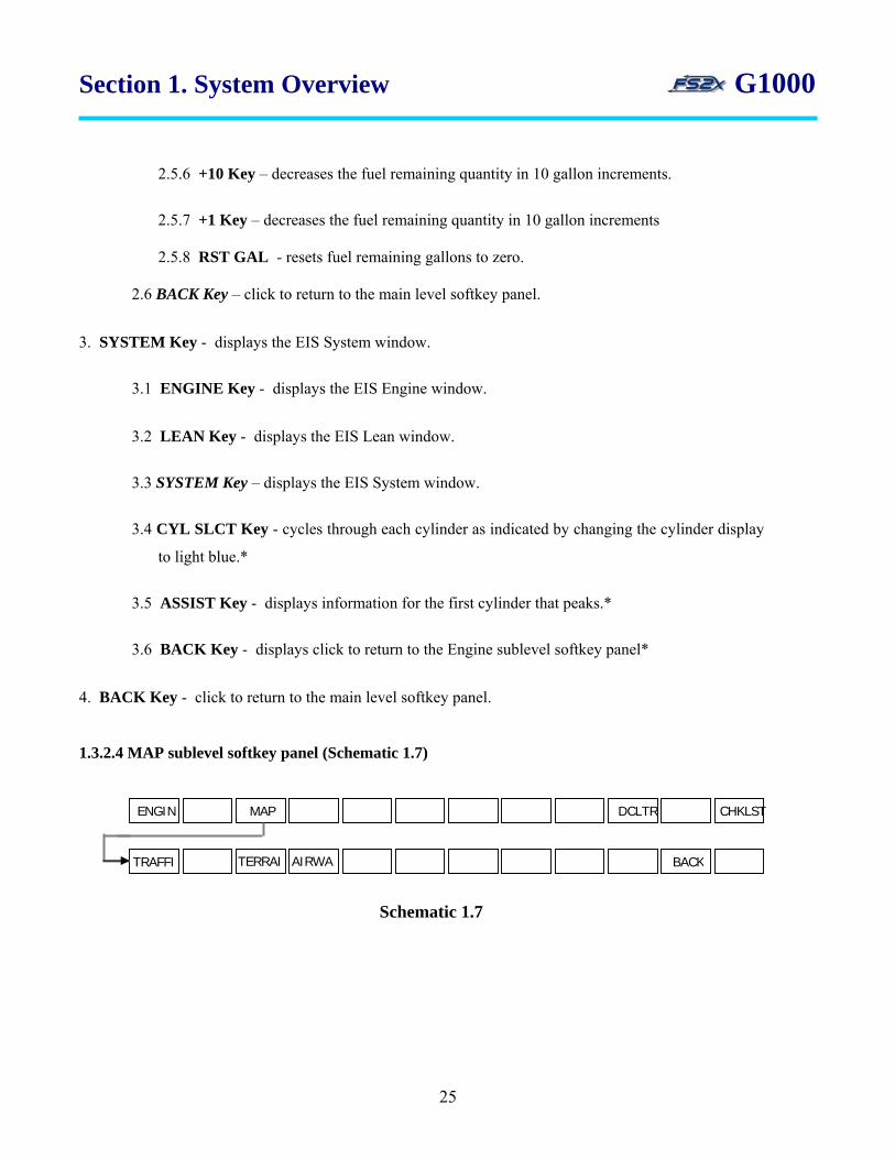
1.3.2.4 MAP sublevel softkey panel (Schematic 1.7)
AIRWA BACK TRAFFI TERRAI
ENGIN CHKLSTDCLTR MAP
Schematic 1.7
25

Section 1. System Overview G1000
1. TRAFFIC Key - displays traffic information on the Navigation Map.
2. TOPO Key - displays topographical data and elevation scale on Navigation Map.
3. TERRAIN Key - displays terrain information on the Navigation Map.
4. AIRWAYS Key - turns on/off Hi and Lo airways on the Navigation Map.
5. BACK Key - click to return to the main level softkey panel.
26
Section 2. Navigation and Communications G1000
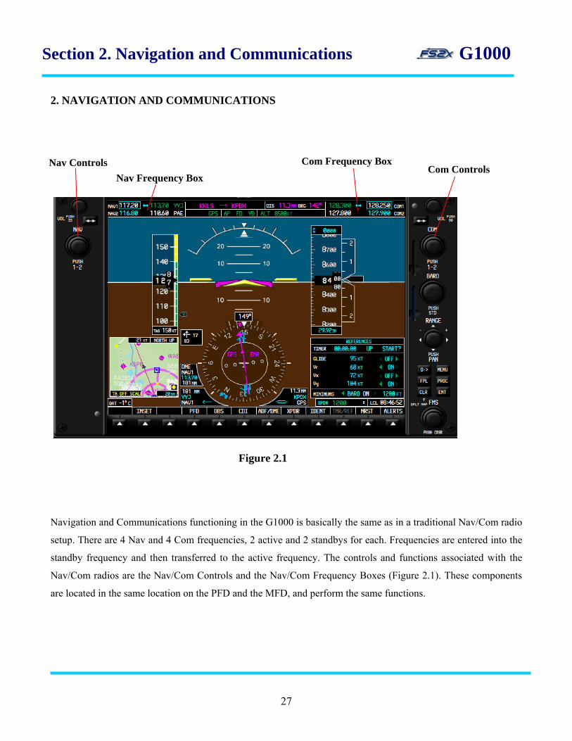
2. NAVIGATION AND COMMUNICATIONS
Figure 2.1 Navigation and Communications functioning in the G1000 is basically the same as in a traditional Nav/Com radio
setup. There are 4 Nav and 4 Com frequencies, 2 active and 2 standbys for each. Frequencies are entered into the
standby frequency and then transferred to the active frequency. The controls and functions associated with the
Nav/Com radios are the Nav/Com Controls and the Nav/Com Frequency Boxes (Figure 2.1). These components
are located in the same location on the PFD and the MFD, and perform the same functions.
Com Frequency Box Com Controls
Nav Frequency Box Nav Controls
27

Section 2. Navigation and Communications G1000
2.1 Nav/Com Controls and Functions
2.1.1 Nav/Com Frequency Boxes
active frequency
station identifier
frequency tuning box
standby frequency
frequency transfer arrow
Figure 2.2
The Nav/Com frequency boxes display the Nav1/Com1 and Nav2/Com2 active and standby frequencies, the
frequency tuning boxes, frequency transfer arrows, and a station identifier (Figure 2.2).
1. active frequencies - Displays the active Nav and Com frequencies. Nav1/Com1 frequencies are listed on the
top line, and Nav2/Com2 are listed on the bottom line.
2. frequency tuning boxes - Cyan rectangles denoting the standby frequency that is ready to be changed. One
for the Nav frequencies and one for the Com frequencies.
3. standby frequencies - Displays the standby Nav and Com frequencies. Nav1/Com1 frequencies are listed on
the top line, and Nav2/Com2 are listed on the bottom line.
4. frequency transfer arrow - Doubled headed arrow denoting, 1) the active and standby frequencies can be
interchanged, and 2) which standby frequency is ready to be transferred.
5. station identifier - Station identifiers associated with the displayed active frequency.
28
Section 2. Navigation and Communications G1000
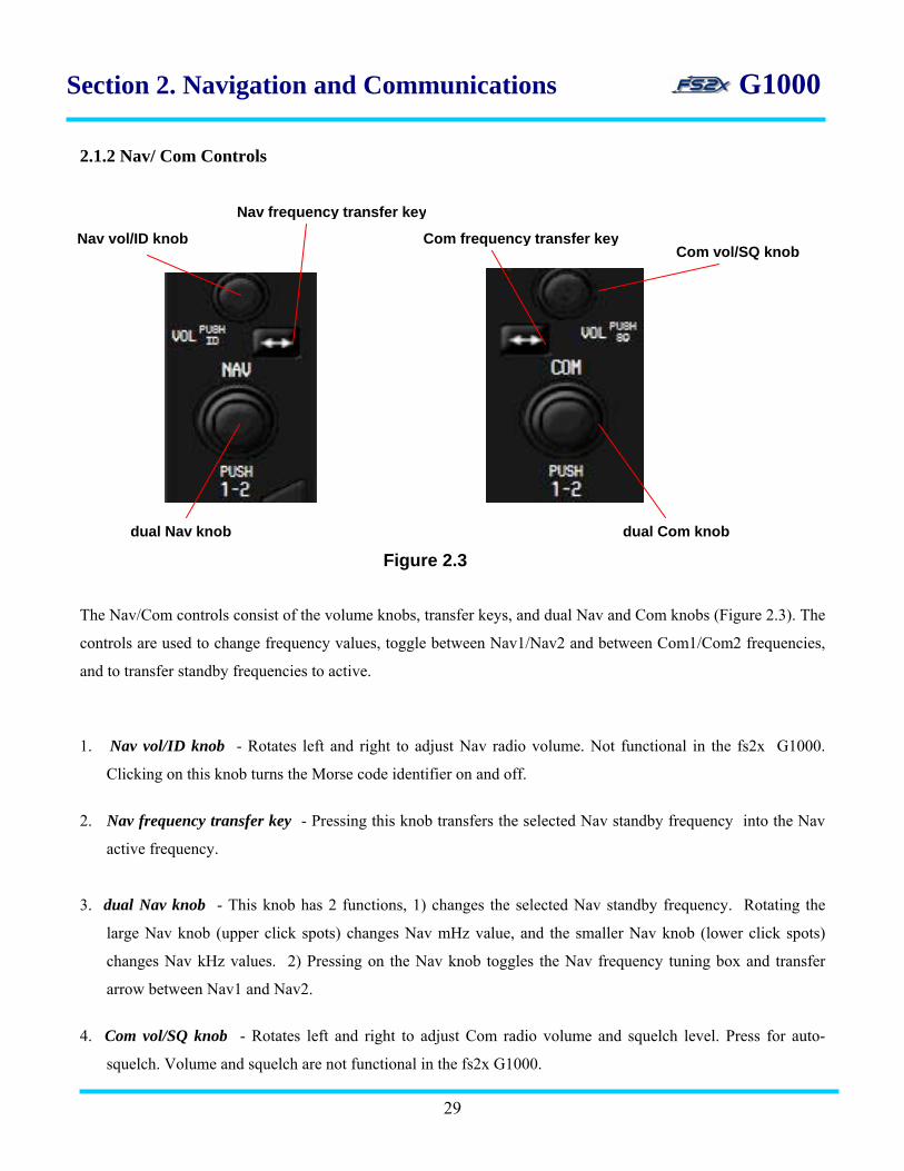
2.1.2 Nav/ Com Controls
The Nav/Com controls consist of the volume knobs, transfer keys, and dual Nav and Com knobs (Figure 2.3). The
controls are used to change frequency values, toggle between Nav1/Nav2 and between Com1/Com2 frequencies,
and to transfer standby frequencies to active.
1. Nav vol/ID knob - Rotates left and right to adjust Nav radio volume. Not functional in the fs2x G1000.
Clicking on this knob turns the Morse code identifier on and off.
2. Nav frequency transfer key - Pressing this knob transfers the selected Nav standby frequency into the Nav
active frequency.
3. dual Nav knob - This knob has 2 functions, 1) changes the selected Nav standby frequency. Rotating the
large Nav knob (upper click spots) changes Nav mHz value, and the smaller Nav knob (lower click spots)
changes Nav kHz values. 2) Pressing on the Nav knob toggles the Nav frequency tuning box and transfer
arrow between Nav1 and Nav2.
4. Com vol/SQ knob - Rotates left and right to adjust Com radio volume and squelch level. Press for auto-
squelch. Volume and squelch are not functional in the fs2x G1000.
29
Nav vol/ID knob Com vol/SQ knob
Nav frequency transfer key
Com frequency transfer key
dual Nav knob dual Com knob
Figure 2.3

Section 2. Navigation and Communications G1000
5. Com frequency transfer key - Pressing this knob transfers the selected Com standby frequency into the Com
active frequency.
6. dual Com knob - This knob has 2 functions, 1) changes the selected Com standby frequency. Rotating the
large Com knob (upper click spots) changes the Com mHz frequency , and the smaller Com knob (lower click
spots) changes the Com kHz frequency.
2) Pressing on the Com knob toggles the Com frequency tuning box and transfer arrow between Com1 and
Com2.
2.1.3 Nav/Com Instructions
2.1.3.1 Change Nav/Com frequencies (Nav and Com are discussed together as Nav/Com)
1. choose the Nav/Com radio, Nav1/Com1 or Nav2/Com2, you want to change by clicking on the dual Nav/Com
knob. The selected radio is denoted by the Nav/Com frequency tuning box and transfer arrow.
2. click on the upper click areas to change the Nav/Com whole number values, and click on the lower click areas
to change the fractional numbers.
3. click on the Nav/Com frequency transfer key to transfer the newly entered frequency into the active frequency.
4. click on the Nav vol/ID knob to hear the Morse code identifier. Click again to turn it off.
2.2 Frequency Auto Tuning
Frequency auto tuning is a function that allows the user to add a frequency directly into the tuning box of the
standby Nav or Com frequency, ready for transfer to the active frequency. Auto tuning from the PFD can be done
from the NRST Apt page. Auto tuning from the MFD can be done from the Airport, NDB, and VOR Information
pages.
2.2.1 auto tuning from the PFD
30
1. click on the PFD NRST to display the nearest airport window (see above link).

Section 2. Navigation and Communications G1000
2. at the NRST apt window click on the large FMS knob (upper click spots) to scroll through the nearest
airports list.
3. click on the small FMS knob (lower click spots) to hilite the selected airport frequency. 4. click on the ENTER key to enter the selected frequency into the selected standby frequency.
5. click on the frequency transfer key to transfer the frequency to the active frequency.
2.2.2 auto tuning from the MFD 1. click on the large FMS knob (upper click spots) to display the current MFD Information page. 2. click on the small FMS knob (lower click spots) to go to the desired Information page. 3. click on the small FMS knob (center) to display the flashing cursor. 4. click on the large FMS knob (upper click spots) to move the cursor and hilite the desired frequency. If more
than 1 frequency is displayed on the Airport Information page, use the small FMS knob (lower click spots)
to scoll to the desired frequency.
5. click on the ENTER key to enter the selected frequency into the selected standby frequency. 6. click on the frequency transfer key to transfer the frequency to the active frequency. 2.3 Emergency Frequency 121.500 MHZ Tuning 1. Click and hold down on the Com Frequency Transfer key for greater than 2 seconds to enter the emergency
frequency directly into the selected active frequency.
31

Section 2. Navigation and Communications G1000
2.5 ADF Radio
Brg1 information window PFD softkey
ADF/DME windowADF/DME dual FMS knob
bearing pointer and compass rose
Figure 2.4
The ADF radio in the G1000 works the same as the traditional ADF radio. Enter the appropriate frequency into
the standby frequency and then transfer it to the active frequency. The difference lies in the way you get and
display the information. The components involved in working the ADF radio includes the ADF/DME Window,
Brg1 Information Window, PFD, BRG1 (not shown), and ADF/DME softkeys, Nav1 bearing pointer, CDI rose,
and the dual FMS knob (Figure 2.6).
32

Section 2. Navigation and Communications G1000
2.6.1 ADF controls and functions
1. Bearing 1 Information Window - The brg1 information window displays the selected Nav1 source. Displays
the ADF frequency, ADF station identifier, and a pointer icon when ADF is selected.
2. Bearing pointer and compass rose - The bearing 1 pointer ‘points’ to the direction of the ADF source on the
rotating compass rose when the Bearing 1 Information Window is set to ADF and an ADF signal is received.
3. PFD, BRG1, and ADF/DME softkeys - The PFD softkey is used to display the PFD softkey panel displaying
the BRG1 softkey. The BRG1 softkey turns the Bearing 1 Information Window on and off and is used to
scroll through the Nav1 choices. The ADF/DME softkey turns the ADF Window on and off.
4. ADF/DME Window - Displays the active and standby ADF frequencies.
5. Dual FMS knob - This knob is used to change the ADF standby frequency.
2.6.2 ADF instructions
2.6.2.1 Change Frequencies
1. click on the ADF/DME softkey to display the ADF Window.
2. click on the large FMS knob (center) to display a flashing cursor behind the first digit of the ADF standby frequency.
3. use the large FMS (upper click spots) to scroll the cursor to the number to be changed and use the small FMS
knob (lower click spots) to change the number.
3. when the number is entered click on the Enter key to transfer the standby frequency to the active frequency.
33
Section 2. Navigation and Communications G1000
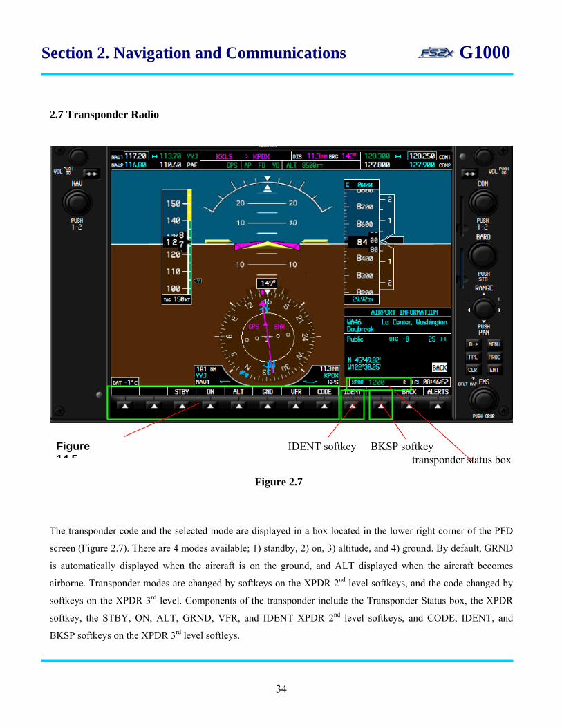
2.7 Transponder Radio
The transponder code and the selected mode are displayed in a box located in the lower right corner of the PFD
screen (Figure 2.7). There are 4 modes available; 1) standby, 2) on, 3) altitude, and 4) ground. By default, GRND
is automatically displayed when the aircraft is on the ground, and ALT displayed when the aircraft becomes
airborne. Transponder modes are changed by softkeys on the XPDR 2nd level softkeys, and the code changed by
softkeys on the XPDR 3rd level. Components of the transponder include the Transponder Status box, the XPDR
softkey, the STBY, ON, ALT, GRND, VFR, and IDENT XPDR 2nd level softkeys, and CODE, IDENT, and
BKSP softkeys on the XPDR 3rd level softleys.
Figure 2.7
Figure 14 5
BKSP softkey IDENT softkey transponder status box
34

Section 2. Navigation and Communications G1000
2.7.1 XPDR controls and functions
1. Transponder Status Box - Displays the transponder 4-digit code on the left side of the box, and the selected
mode on the right side, each in green color. The white colored R indicates the ability of the transponder to reply to
interrogations.
2. XPDR softkey - Changes the softkey level to the XPDR 2nd level softkeys.
3. STBY, ON, ALT, and GRND softkeys – Turns the corresponding transponder modes on and off. Selected
mode is displayed in the Transponder Status box. XPDR 2nd level softkeys.*
4. VFR softkey - Enters the VFR code 1200 directly into the transponder.
4. CODE softkey - Changes the softkey level from the XPDR 2nd level softkeys to the XPDR 3rd level softkeys
containing the code selection softkeys.
5. IDENT softkey - Sends unique ID signal for 18 seconds.*
6. Code Selection softkeys - Enter numbers into the transponder code. Clicking a number enters that number
into the code at the digit, and moves the blinking cursor 1 digit to the right.
7. BKSP softkey - Backspace key moves the blinking cursor backwards through the code digits to re-enter
values as needed.
2.7.2 XPDR Instructions
2.7.2.1 Change Code
1. click on the XPDR softkey on the default, or primary, softkey level to go to the XPDR 2nd level softkeys. 2. click on the XPDR 2nd level CODE softkey to change to the XPDR 3rd level softkeys. 3. at the XPDR 3rd level softkeys, the transponder code display will have a blinking cursor behind one of the code
digits ready to be changed.
35

Section 2. Navigation and Communications G1000
4. click on the desired number softkey to enter that number into the code. This will also move the blinking cursor
1 digit to the right, and ready to enter a new number into that digit.
5. Continue entering numbers as described above until the code is completed.
6. To change a number after the cursor has passed to its right, click on the BKSP softkey to scroll the cursor back
to the left behind the digit to be changed and then use the numbered softkey as before.
2.7.2.2 Change Mode
1. click on the XPDR softkey on the default, or primary, softkey level to go to the XPDR 2nd level softkeys.
2. click on any of the Mode Selection softkeys to turn it on or off, and to enter the designation into the
Transponder Status box display. No functional significance in the fs2x G1000.
2.7.2.3 Change Miscellaneous
1. click on the VFR softkey to directly change the transponder code to the VFR code 1200. The VFR code will be
displayed in the Transponder Status box. Click again to return to the previous code.
2. click on the IDENT softkey on the XPDR 2nd or 3rd level softkeys to send a unique identifying ID signal.
3. click on the BACK softkey on any level to return to the upper levels
36
Section 3. Flight Instruments G1000 3. FLIGHT INSTRUMENTS
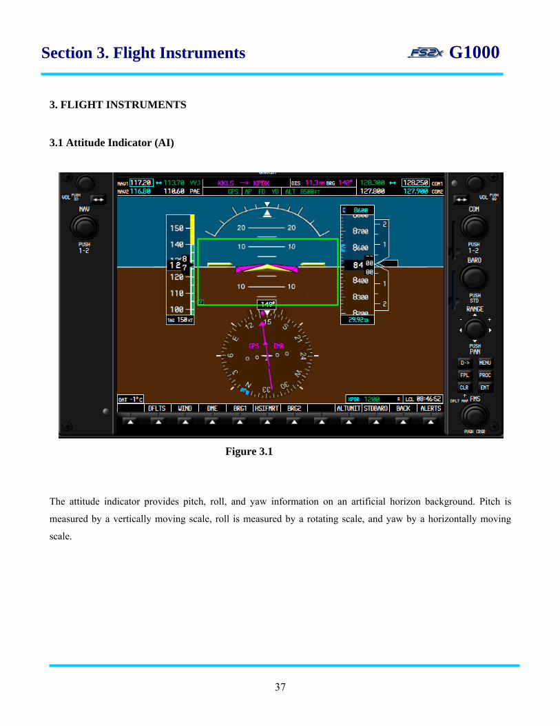
3.1 Attitude Indicator (AI)
Figure 3.1
The attitude indicator provides pitch, roll, and yaw information on an artificial horizon background. Pitch is
measured by a vertically moving scale, roll is measured by a rotating scale, and yaw by a horizontally moving
scale.
37
Section 3. Flight Instruments G1000
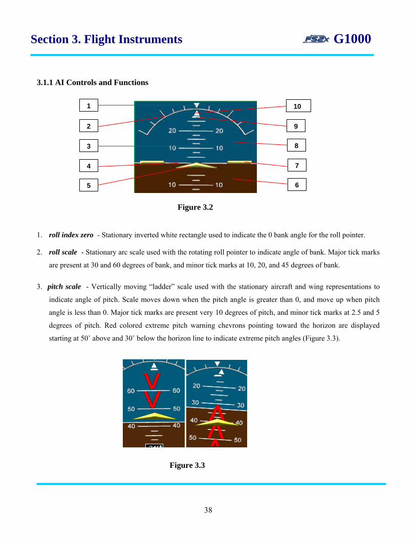
3.1.1 AI Controls and Functions
Figure 3.2
1. roll index zero - Stationary inverted white rectangle used to indicate the 0 bank angle for the roll pointer.
2. roll scale - Stationary arc scale used with the rotating roll pointer to indicate angle of bank. Major tick marks
are present at 30 and 60 degrees of bank, and minor tick marks at 10, 20, and 45 degrees of bank.
3. pitch scale - Vertically moving “ladder” scale used with the stationary aircraft and wing representations to
indicate angle of pitch. Scale moves down when the pitch angle is greater than 0, and move up when pitch
angle is less than 0. Major tick marks are present very 10 degrees of pitch, and minor tick marks at 2.5 and 5
degrees of pitch. Red colored extreme pitch warning chevrons pointing toward the horizon are displayed
starting at 50˚ above and 30˚ below the horizon line to indicate extreme pitch angles (Figure 3.3).
Figure 3.3
1 10
7
8
2
3
4
5
9
6
38
Section 3. Flight Instruments G1000 4. horizon line - Represents the “horizon” separating ground from sky. 5. aircraft symbol - Symbol representing an aircraft used as a stationary reference for the pitch scale.
6. ground representation - Represents the ground.
7. aircraft wingtips - Symbols representing aircraft wings used as a stationary reference for the pitch scale.
8. sky representation - Represents the sky.
9. slip/skid indicator - Indicates lateral acceleration. Moves in the opposite direction of the roll pointer. One
lateral displacement is equivalent to one ball displacement in a traditional indicator.
10. roll pointer - Indicates angle of bank. Rotates left and right over the roll scale and ‘points’ to the angle of
bank.
3.1.2 AI Instructions
-None
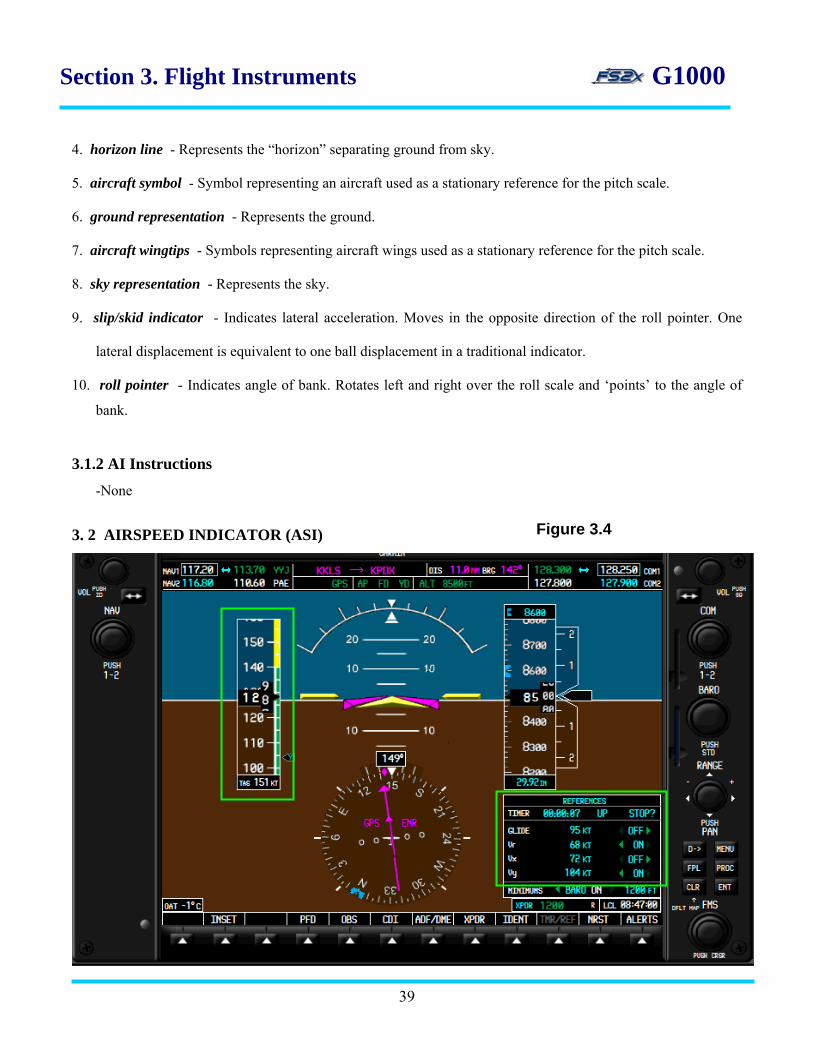
3. 2 AIRSPEED INDICATOR (ASI)
39
Figure 3.4
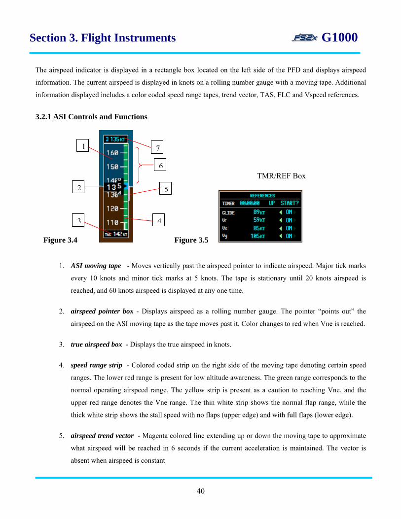
Section 3. Flight Instruments G1000 The airspeed indicator is displayed in a rectangle box located on the left side of the PFD and displays airspeed
information. The current airspeed is displayed in knots on a rolling number gauge with a moving tape. Additional
information displayed includes a color coded speed range tapes, trend vector, TAS, FLC and Vspeed references.
3.2.1 ASI Controls and Functions
Figure 3.4 Figure 3.5
1. ASI moving tape - Moves vertically past the airspeed pointer to indicate airspeed. Major tick marks
every 10 knots and minor tick marks at 5 knots. The tape is stationary until 20 knots airspeed is
reached, and 60 knots airspeed is displayed at any one time.
2. airspeed pointer box - Displays airspeed as a rolling number gauge. The pointer “points out” the
airspeed on the ASI moving tape as the tape moves past it. Color changes to red when Vne is reached.
3. true airspeed box - Displays the true airspeed in knots.
4. speed range strip - Colored coded strip on the right side of the moving tape denoting certain speed
ranges. The lower red range is present for low altitude awareness. The green range corresponds to the
normal operating airspeed range. The yellow strip is present as a caution to reaching Vne, and the
upper red range denotes the Vne range. The thin white strip shows the normal flap range, while the
thick white strip shows the stall speed with no flaps (upper edge) and with full flaps (lower edge).
5. airspeed trend vector - Magenta colored line extending up or down the moving tape to approximate
what airspeed will be reached in 6 seconds if the current acceleration is maintained. The vector is
absent when airspeed is constant
6
5
4
1
2
3
7
TMR/REF Box
40

Section 3. Flight Instruments G1000
6. Vspeed references - Displayed as black pointers with corresponding Vspeed reference letters inside
that point to the appropriate airspeed on the moving tape. Available Vspeeds include best glide (G),
rotation speed (R), best rate-of-climb (X), and best angle-of-climb (Y). The pointer boxes are not
displayed by default, but can be tu rned on and off in the TMR/REF Box.
3.2.2 ASI Instructions
The Vspeed references are the only ASI components that can be changed by the user. As discussed above, this is
done in the TMR/REF Box.
3.3 ALTIMETER (ALT)
Figure 3.6
The altimeter is displayed in a rectangle box located on the right side of the PFD and displays altitude
information. The current altitude is displayed in feet on a rolling number gauge with a moving tape. Additional
information displayed includes an altitude reference bug, an altitude trend vector, altitude reference box, altitude
41

Section 3. Flight Instruments G1000
alerting, and a barometric display box (figure 3.6). The dual Altitude and the CRS/BARO knobs are used to
change altitude selection and barometer settings, respectively. The altitude reference and barometric values can be
displayed in metric using the METRIC softkey.
3.3.1 ALT Controls and Functions
Figure 3.7
1. altitude reference bug - Indicates the reference altitude on the ALT moving tape. Remains at the edge of the
box closest to the reference altitude when the reference altitude is out of range.
2. altitude pointer box - Displays the current altitude in 20 knot increments as a rolling number gauge. The
pointer points to the altitude on the ALT moving tape as the tape moves past it.
3. ALT moving tape - Moves vertically past the altitude pointer to indicate altitude. Major tick marks every 100
feet and minor tick marks at 20 feet. Six hundred feet of altitude is displayed at any one time.
4. altitude reference box - Displays the reference altitude in feet (ASL). The reference altitude is set by the user
(see below), and is the altitude used by the autopilot when the altitude mode is engaged (AP/ALT link). The
reference altitude box also serves as a visual altitude alerting system when the autopilot is on and the altitude
mode is engaged (Figure 3.8).
1
2
3
4
5
6
within 1000 ft within 200 ft deviation +/-200 ft
Figure 3.8
42
Section 3. Flight Instruments G1000
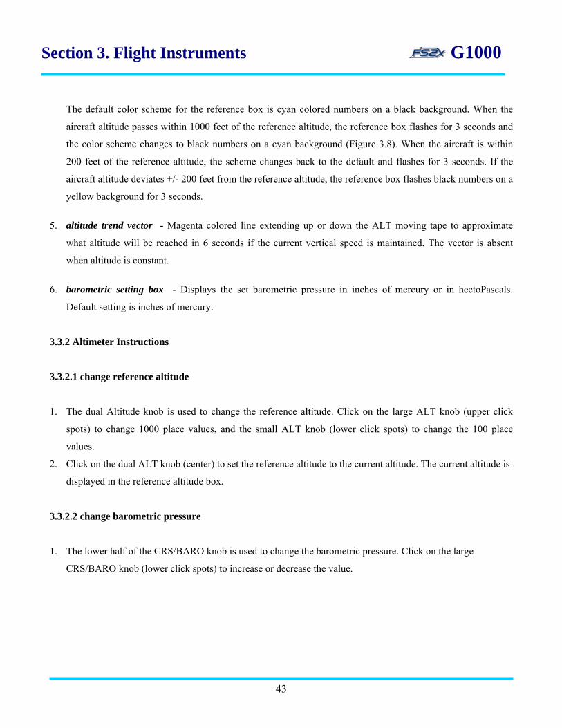
The default color scheme for the reference box is cyan colored numbers on a black background. When the
aircraft altitude passes within 1000 feet of the reference altitude, the reference box flashes for 3 seconds and
the color scheme changes to black numbers on a cyan background (Figure 3.8). When the aircraft is within
200 feet of the reference altitude, the scheme changes back to the default and flashes for 3 seconds. If the
aircraft altitude deviates +/- 200 feet from the reference altitude, the reference box flashes black numbers on a
yellow background for 3 seconds.
5. altitude trend vector - Magenta colored line extending up or down the ALT moving tape to approximate
what altitude will be reached in 6 seconds if the current vertical speed is maintained. The vector is absent
when altitude is constant.
6. barometric setting box - Displays the set barometric pressure in inches of mercury or in hectoPascals.
Default setting is inches of mercury.
3.3.2 Altimeter Instructions
3.3.2.1 change reference altitude
1. The dual Altitude knob is used to change the reference altitude. Click on the large ALT knob (upper click
spots) to change 1000 place values, and the small ALT knob (lower click spots) to change the 100 place
values.
2. Click on the dual ALT knob (center) to set the reference altitude to the current altitude. The current altitude is
displayed in the reference altitude box.
3.3.2.2 change barometric pressure
1. The lower half of the CRS/BARO knob is used to change the barometric pressure. Click on the large
CRS/BARO knob (lower click spots) to increase or decrease the value.
43

Section 3. Flight Instruments G1000 3.3.3 Altimeter metric display
3.3.3.1 metric instructions
1. click on the PFD softkey on the main softkey panel.
2. click on the ALT UNIT softkey on the PFD 2nd level softkey panel.
3. click on the METERS softkey on the PFD 3rd level softkey panel to display the altitude and reference altitude
in meters. Click again to turn the metric display off.
4. click on the HPA softkey on the PFD 3rd level softkey panel to display the barometric pressure in
hectopascals.
5. click on the IN softkey on the PFD 3rd level softkey panel to display the barometric pressure in inches.
metric barometric pressure
metric altitude
Figure 3.9
metric reference altitude 123mt
635mt
1013hpa
44
Section 3. Flight Instruments G1000
3.4 Vertical Speed Indicator (VSI)
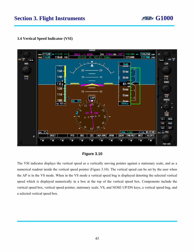
The VSI indicator displays the vertical speed as a vertically moving pointer against a stationary scale, and as a
numerical readout inside the vertical speed pointer (Figure 3.10). The vertical speed can be set by the user when
the AP is in the VS mode. When in the VS mode a vertical speed bug is displayed denoting the selected vertical
speed which is displayed numerically in a box at the top of the vertical speed box. Components include the
vertical speed box, vertical speed pointer, stationary scale, VS, and NOSE UP/DN keys, a vertical speed bug, and
a selected vertical speed box.
Figure 3.10
45

Section 3. Flight Instruments G1000 3.4.1 VSI controls and functions
1. vertical speed box - the vertical speed box is attached to the right side of the Altitude Box and displays the
vertical speed associated values.
2. stationary scale - vertical scale used as a reference for the Vertical Speed Pointer. Hash marks are displayed
at every +/-500 feet of vertical speed, to a maximum of +/-2000 feet. Numbers displayed represent x1000.
3. vertical speed bug - moves up and down the left side of the stationary scale to denote the selected vertical
speed. Displayed only when the AP is in the VS mode. NOSE UP/DN keys move the bug.
4. selected vertical speed - numeric display of the selected vertical speed when the AP is in the VS mode. Set
using the NOSE UP/DN keys in the AP group.
5. vertical speed pointer - vertically moving pointer denoting the current vertical speed on the stationary scale.
Also displays the numerical vertical speed in feet per minute inside.
Figure 3.11
vertical speed bug
vertical speed box selected vertical speed
vertical speed pointer
stationary scale
46

Section 3. Flight Instruments G1000 3.4.2 VSI Instructions
1. To set the selected vertical speed to a different value, click on the VS key. 2. Click on the NOSE UP and NOSE DN keys to increase and decrease the selected vertical speed value.
3.5 Vertical Deviation/Glidepath/Glideslope Indicator (VDI)
The VDI provides vertical situational awareness prior to and during an Approach using an indicator moving
vertically over a fixed scale (Figure 3.12). When the VNV mode is functional, a Vertical Deviation Indicator is
displayed to show deviation from the required vertical path. A magenta colored Glidepath Indicator is displayed
when GPS is being used during an approach. A green colored Glideslope Indicator is displayed when flying an
LOC type approach. Components of the VDI system include the Vertical Deviation box, a fixed Vertical
Deviation Scale, 3 different indicators, a VDI Mode box, the VNV key, and the Nav radio.
Figure 3.12
47
Section 3. Flight Instruments G1000 3.5.1 VDI controls and functions
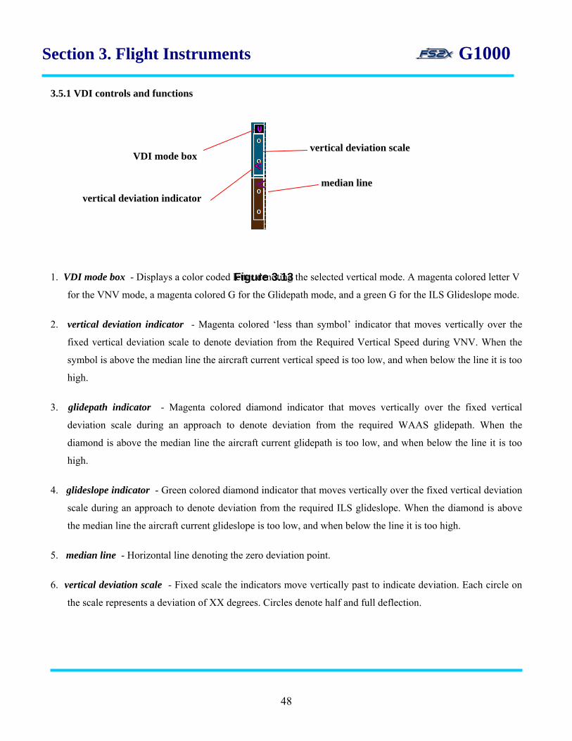
1. VDI mode box - Displays a color coded letter denoting the selected vertical mode. A magenta colored letter V
for the VNV mode, a magenta colored G for the Glidepath mode, and a green G for the ILS Glideslope mode.
2. vertical deviation indicator - Magenta colored ‘less than symbol’ indicator that moves vertically over the
fixed vertical deviation scale to denote deviation from the Required Vertical Speed during VNV. When the
symbol is above the median line the aircraft current vertical speed is too low, and when below the line it is too
high.
3. glidepath indicator - Magenta colored diamond indicator that moves vertically over the fixed vertical
deviation scale during an approach to denote deviation from the required WAAS glidepath. When the
diamond is above the median line the aircraft current glidepath is too low, and when below the line it is too
high.
4. glideslope indicator - Green colored diamond indicator that moves vertically over the fixed vertical deviation
scale during an approach to denote deviation from the required ILS glideslope. When the diamond is above
the median line the aircraft current glideslope is too low, and when below the line it is too high.
5. median line - Horizontal line denoting the zero deviation point.
6. vertical deviation scale - Fixed scale the indicators move vertically past to indicate deviation. Each circle on
the scale represents a deviation of XX degrees. Circles denote half and full deflection.
<
VDI mode box
vertical deviation indicator
vertical deviation scale
Figure 3.13
median line
48

Section 3. Flight Instruments G1000 3.5.2 VDI Instructions
1. vertical deviation - click on the VNV key to begin navigating according to the VNV, or go to the VNV page
on the MFD and follow the instructions given for VNV (VNV link) .
2. glidepath - click on the CDI softkey from the main level softkeys to display the GPS mode. Enter an
Approach Procedure.
3. glideslope - click on the CDI softkey from the main level softkeys to display the Nav1 mode. Tune in an
active ILS frequency on the active Nav radio as discussed earlier.
3.6 Horizontal Situation Indicator (HSI)
The HSI provides horizontal situational information at all times during a flight (Figure 3.14). This includes
Figure 3.14
49

Section 3. Flight Instruments G1000 information derived from a compass rose, CDI, bearing pointers, and several information windows. Additional
information can be obtained by the on-board DME.
3.6.1 HSI controls and functions heading box
turn rate indicator lubber line ground track bug
lateral deviation scale course deviation indicator
navigation source
rotating compass rose aircraft symbol
heading bug
flight phase
course pointer
To/From indicator
Figure 3.14
1. ground track bug - Denotes on the Rotating Compass Rose the heading of the aircraft over the ground.
2. turn rate indicator - Tick marks to the left and right of the lubber line denoting half-standard and standard
turn rates.
3. course pointer - The Course Pointer points to the set course direction on the Rotating Compass Rose. The
pointer is displayed as a single, magenta colored arrow for GPS, a single green colored arrow for Nav1
(VOR2, LOC2) and Nav2 (VOR2, LOC2).
4. navigation source - Digital display of the current source of navigation. Magenta colored for GPS, and green
for Nav1 and Nav2.
5. course deviation indicator - Moves laterally across the Lateral Deviation Scale to indicate relative deviation
from the set course. Full scale deflection changes automatically for different phases of flight (Table 3.1).
Magenta colored for GPS navigation and green colored for Nav1 and Nav2.
50

Section 3. Flight Instruments G1000 5. lateral deviation scale - Scale that rotates with the Course Deviation Indicator to provide lateral deviation
information. Scale deflection value changes with different phases of flight (Table 3.1). Values can be changed
on the MFD System Setup Auxiliary Page . Circles denote half and full deflection.
6.
Flight Phase Auto CDI Full-scale Deflection
Departure 0.3 nm
Terminal 1.0 nm
Enroute 2.0 nm
Approach 1.0 nm decreasing to 350 ft
Missed Approach 0.3 nm
7. rotating compass rose - Rotates past the Lubber Line to indicate the aircraft heading. Also used as a
reference for the various pointers and bugs. Displayed in a heading-up orientation. Letters are displayed at the
cardinal points and numbers every 30 degrees. Major tick marks are present every 10 degrees, and minor tick
marks every 5 degrees.
8. aircraft symbol - Self explanatory.
9. OBS mode - Displays OBS when the navigation source is GPS and the OBS mode is active . Displays SUSP
when the OBS mode is active to denote waypoint sequencing is suspended. Displays DR when navigating by
Dead Reckoning due to GPS failure.*
10. To/From indicator - Closed arrowhead on the Course Pointer that points in the same direction as the course
pointer when the navigation source is in the forward direction, and points in the opposite direction when the
source is in the reverse direction.
11. flight phase - Digital display of the current phase of flight. Magenta colored for GPS navigation and green
colored for Nav1 and Nav2.
Table 3.1
51
Section 3. Flight Instruments G1000 12. heading bug - Denotes the set heading. Become ‘active’ when in the heading navigation mode on autopilot.
13. turn rate and heading vector - Magenta colored vector showing the current turn rate. The end of the vector
predicts what the heading will be in 6 seconds at the current rate of turn. Absent if the turn rate exceeds 4 deg
per second. Currently not available in the fs2x G1000.
14. lubber line - Fixed, closed white triangle pointing to the aircraft heading on the Rotating Compass Rose.
15. heading box - Displays the current aircraft heading.
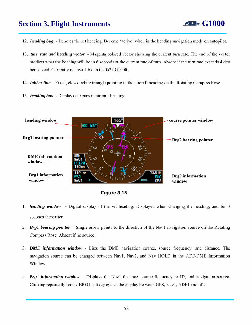
1. heading window - Digital display of the set heading. Displayed when changing the heading, and for 3
seconds thereafter.
2. Brg1 bearing pointer - Single arrow points to the direction of the Nav1 navigation source on the Rotating
Compass Rose. Absent if no source.
3. DME information window - Lists the DME navigation source, source frequency, and distance. The
navigation source can be changed between Nav1, Nav2, and Nav HOLD in the ADF/DME Information
Window.
4. Brg1 information window - Displays the Nav1 distance, source frequency or ID, and navigation source.
Clicking repeatedly on the BRG1 softkey cycles the display between GPS, Nav1, ADF1 and off.
DME information window
Brg1 information window
Brg2 information window
Brg2 bearing pointer Brg1 bearing pointer
Figure 3.15
heading window course pointer window
52

Section 3. Flight Instruments G1000
5. Brg2 information window - Displays the Nav2 distance, source frequency or ID, and navigation source.
Clicking repeatedly on the BRG1 softkey cycles the display between GPS, Nav2, ADF2 and off.
6. Brg2 bearing pointer - Double arrow points to the direction of the Nav2 navigation source on the Rotating
Compass Rose. Absent if no source.
7. course window - Digital display of the set course. Displayed when changing the course using the
CRS/BARO knob, and for 3 seconds thereafter.
3.6.2 HSI instructions
3.6.2.1 CDI There are 3 different CDI modes possible. The different modes are selected using the CDI softkey.
1. GPS
- the GPS CDI is the default display. Click on CDI softkey to choose GPS navigation if required.
- enter a waypoint(s) using the Direct To or Flight Planning function .
- click on the CRS/BARO knob (upper click spots) to rotate the Course Pointer and the Course Deviation
Indicator until the they are aligned.
- alternatively, click on the CRS/BARO knob to directly align the pointer and indicator to the GPS bearing.
2. Nav1
- enter the desired frequency into the Nav1 Active Frequency.
- click on the CDI softkey to select the Nav1 mode.
- click on the CRS/BARO knob (upper click spots) to rotate the Course Pointer and the Course Deviation
Indicator until the they are aligned.
- alternatively, click on the CRS/BARO knob to directly align the pointer and indicator to the Nav1 bearing.
3. Nav2
- enter the desired frequency into the Nav2 Active Frequency.
- click on the CDI softkey to select the Nav2 mode.
53

Section 3. Flight Instruments G1000
- click on the CRS/BARO knob (upper click spots) to rotate the Course Pointer and the Course Deviation
Indicator until the they are aligned.
- alternatively, click on the CRS/BARO knob to directly align the pointer and indicator to the Nav2 bearing.
3.6.2.2 Nav information windows and bearing pointers The bearing information pointers are always displayed when their corresponding bearing information window is
displayed. The bearing information windows display the bearing source, a pointer icon, source frequency (or
identifier), and the distance to the source. Navigation information is displayed in the left box for Nav1 (GPS,
Nav1, ADF1), and in the right box for Nav2 (GPS, Nav2, ADF1). The source frequency is replaced with the
source identifier if the mode is GPS or, if Nav1 or Nav2, when the source is in range. If no signal is received, the
source frequency is replaced with “NO DATA”. The source frequency is replaced with an ILS annotation if the
source is Nav and an ILS frequency is tuned and received as the active frequency.
1. enter the desired frequency into the Nav1 or Nav2 Active Frequency. 2. click on the PFD softkey to display the 2nd level PFD softkeys. 3. successive clicking on the BRG1 or BRG2 softkey toggles the information window displays between the
different navigation sources.
54
Section 3. Flight Instruments G1000
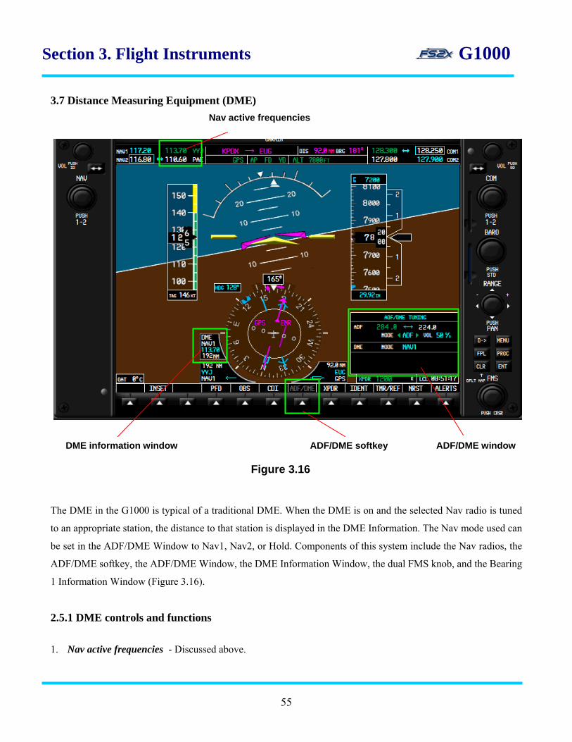
3.7 Distance Measuring Equipment (DME)
The DME in the G1000 is typical of a traditional DME. When the DME is on and the selected Nav radio is tuned
to an appropriate station, the distance to that station is displayed in the DME Information. The Nav mode used can
be set in the ADF/DME Window to Nav1, Nav2, or Hold. Components of this system include the Nav radios, the
ADF/DME softkey, the ADF/DME Window, the DME Information Window, the dual FMS knob, and the Bearing
1 Information Window (Figure 3.16).
2.5.1 DME controls and functions
1. Nav active frequencies - Discussed above.
DME information window ADF/DME softkey ADF/DME window
Figure 3.16
Nav active frequencies
55

Section 3. Flight Instruments G1000 2. DME information Window - This window displays the Nav mode, the Nav frequency, and the distance in
nautical miles to the source.
3. ADF/DME softkey - Used to display the ADF/DME Window. Click to turn on and off. 4. ADF/DME Window - DME part displays the selected Nav mode. A popup window gives the user the ability
to choose between Nav1, Nav2, and Hold modes (Figure 3.17).
3.7.1 DME instructions
1. enter the Nav source frequency into the active frequency of the selected Nav radio as discussed above. 2. click on ADF/DME softkey to display the ADF/DME Window. 3. click on the FMS knob (center) and then turn the large FMS (upper click spots) to scroll the blinking field to
the Nav mode display.
4. turn the small FMS knob (lower click spots) to display the Nav mode choice window. 5. turn the large FMS (upper click spots) to scroll the blinking field to the appropriate mode choice. 6. click the Enter key to enter the chosen mode, and to remove the display.
7. display the DME Information Window (DME Info link).
Figure 3.17
Nav mode choice window
56
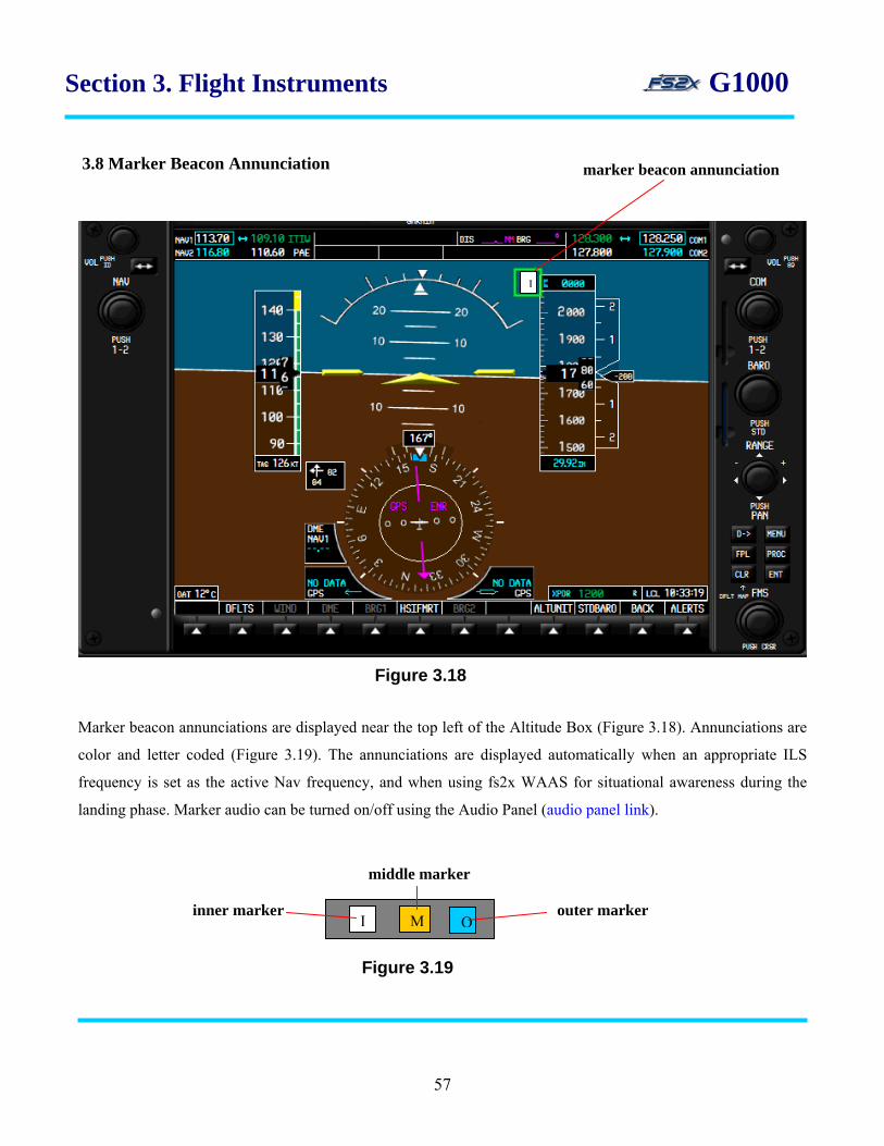
Section 3. Flight Instruments G1000 3.8 Marker Beacon Annunciation
Marker beacon annunciations are displayed near the top left of the Altitude Box (Figure 3.18). Annunciations are
color and letter coded (Figure 3.19). The annunciations are displayed automatically when an appropriate ILS
frequency is set as the active Nav frequency, and when using fs2x WAAS for situational awareness during the
landing phase. Marker audio can be turned on/off using the Audio Panel (audio panel link).
I
Figure 3.18
I M O
marker beacon annunciation
Figure 3.19
inner marker outer marker
middle marker
57

Section 3. Flight Instruments G1000 3.9 Wind Data
Wind data is displayed in the Wind Data Box (Figure 3.20). It is off by default and turned on and off using the
PFD and WIND (PFD 2nd level) softkeys. There are 3 wind data display options (Figure 3.21).
3.9.1 Wind data controls and functions
Option 1 - Displays wind direction arrows with numeric headwind and crosswind components. Option 2 - Displays wind direction arrow and numeric speed. Option 3 - Displays wind direction arrow with numeric direction and speed.
58
wind data box wind data softkeys Figure 3.20
option 1 option 2 option 3
Figure 3.21
Section 3. Flight Instruments G1000 3.9.2 Wind data instructions
1. click on the PFD softkey to display the PFD 2nd levels softkeys.
2. click on the WIND softkey on the PFD 2nd level softkeys to display the Wind Option softkeys.
3. click on the appropriate Wind Option softkey at any time to display the desired Wind Option Box. 4. click on the OFF softkey to remove the Wind Option Box. 5. click on the BACK softkey to return to a higher softkey level.
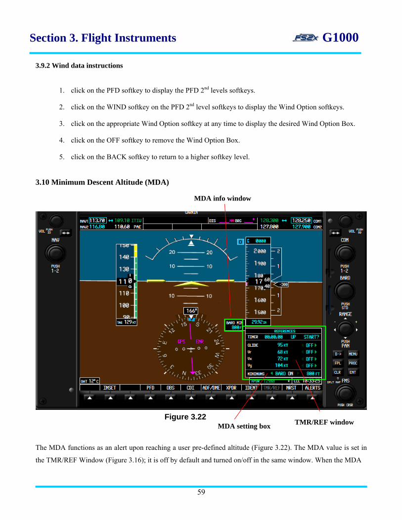
3.10 Minimum Descent Altitude (MDA)
MDA info window
The MDA functions as an alert upon reaching a user pre-defined altitude (Figure 3.22). The MDA value is set in
the TMR/REF Window (Figure 3.16); it is off by default and turned on/off in the same window. When the MDA
59
Figure 3.22 TMR/REF window MDA setting box
Section 3. Flight Instruments G1000
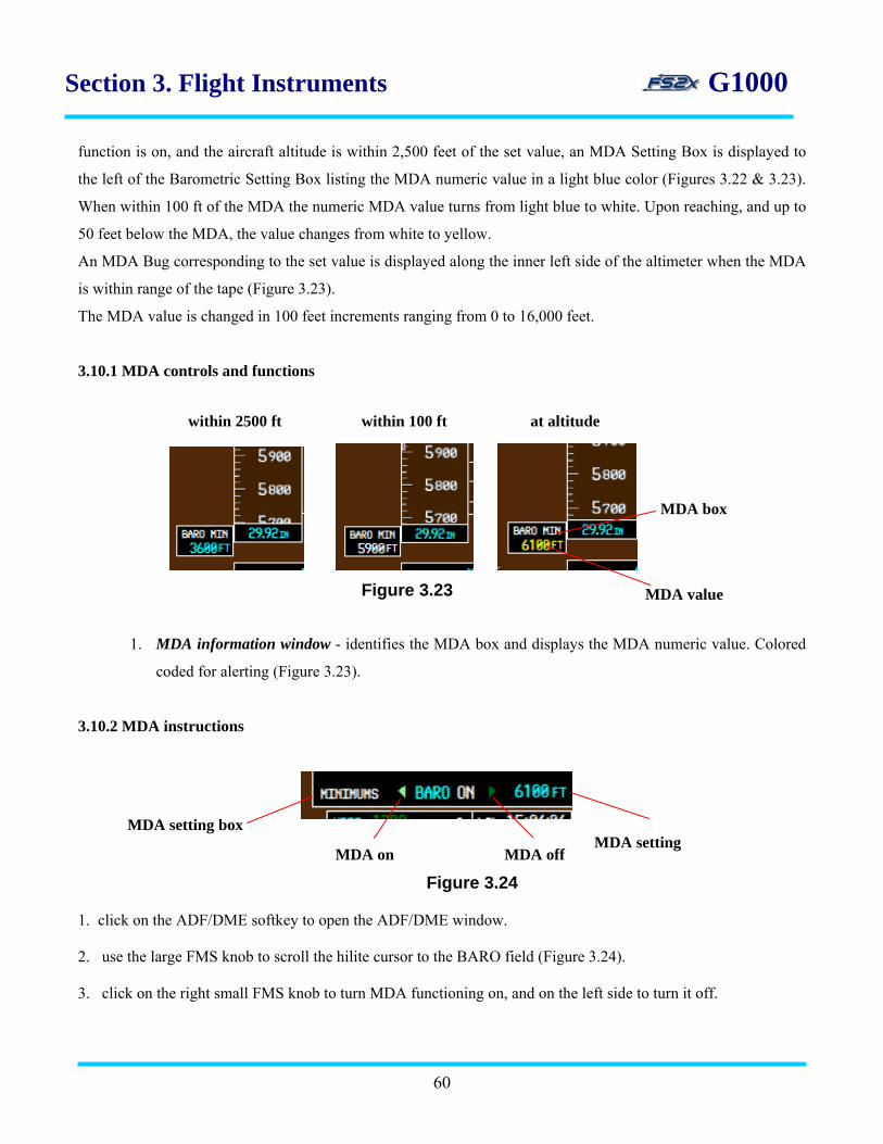
function is on, and the aircraft altitude is within 2,500 feet of the set value, an MDA Setting Box is displayed to
the left of the Barometric Setting Box listing the MDA numeric value in a light blue color (Figures 3.22 & 3.23).
When within 100 ft of the MDA the numeric MDA value turns from light blue to white. Upon reaching, and up to
50 feet below the MDA, the value changes from white to yellow.
An MDA Bug corresponding to the set value is displayed along the inner left side of the altimeter when the MDA
is within range of the tape (Figure 3.23).
The MDA value is changed in 100 feet increments ranging from 0 to 16,000 feet.
3.10.1 MDA controls and functions
1. MDA information window - identifies the MDA box and displays the MDA numeric value. Colored
coded for alerting (Figure 3.23).
3.10.2 MDA instructions
1. click on the ADF/DME softkey to open the ADF/DME window.
2. use the large FMS knob to scroll the hilite cursor to the BARO field (Figure 3.24). 3. click on the right small FMS knob to turn MDA functioning on, and on the left side to turn it off.
60
Figure 3.23
MDA on MDA off
MDA setting box
Figure 3.24
MDA setting
MDA value
MDA box
at altitude within 100 ft within 2500 ft

Section 3. Flight Instruments G1000
4. click on the large FMS knob to move the cursor to the MDA value field, and then click on the small FMS knob
to change the value. Click on the right side to increase the value, and click on the left side to decrease it.
3.11 TMR/REF Window
The Timer/Reference window has 2 functions: 1) a generic timer, and 2) a place to set and turn on/off references
speeds (Figure 3.25).
3.11.1 Generic timer
The generic timer is located at the top of the TMR/REF Window and has Count-Up, Count-Down, Start, Stop,
and Reset functionalities. Time is displayed in an hrs:mins:secs format from zero up to 99 hours, 59 minutes, and
timer display Figure 3.25
ref speed bugs
ref speeds
61

Section 3. Flight Instruments G1000
59 seconds. The timer can be stopped, reset, or re-started in the Count-Up or the Count-Down mode at any time of
functioning.
3.11.1.1 Timer controls and functions
1. hrs:mins:secs field - displays the time used in Count-Up and Count-Down modes. 2. Up/Dn field - displays the current timer mode; Up or Down. 3. start/stop/reset field - displays the current timer function choice. Timer instructions 1. click on the TMR/REF softkey to display the TMR/REF Window. The ‘START?’ field will be highlighted.
2. click on the ENTER button to begin timing up from 0, or use the large FMS to scroll to the time field. Use the
small FMS knob to change the highlighted value. 3. click on the ENTER button when the desired value has been entered. The cursor will move to the UP/DN field.
Use the small FMS knob to toggle between the 2 choices. 4. click the Enter button to accept your choice and move the cursor to the start/stop/reset field.
5. click on the ENTER button when the start/stop/reset field is highlighted to scroll through the choices (see #8
below). Clicking on the ENTER button when a field is highlighted will also perform that function. 6. counting up or down can be interchanged at any time by switching the Up/DN function. 7. when 0 is reached in the count down mode, the mode switches to count up and begins to count up.
8. Start, Stop, and Reset functions are as follows: 1) start: starts timer functioning in the Up and Down modes.
Figure 3.26
hrs:mins:secs field Up/DN field start/stop/reset field
62
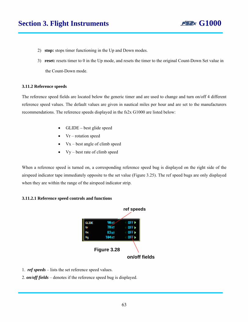
Section 3. Flight Instruments G1000
2) stop: stops timer functioning in the Up and Down modes. 3) reset: resets timer to 0 in the Up mode, and resets the timer to the original Count-Down Set value in the Count-Down mode.
3.11.2 Reference speeds The reference speed fields are located below the generic timer and are used to change and turn on/off 4 different
reference speed values. The default values are given in nautical miles per hour and are set to the manufacturers
recommendations. The reference speeds displayed in the fs2x G1000 are listed below:
• GLIDE – best glide speed
• Vr – rotation speed
• Vx – best angle of climb speed
• Vy – best rate of climb speed
When a reference speed is turned on, a corresponding reference speed bug is displayed on the right side of the
airspeed indicator tape immediately opposite to the set value (Figure 3.25). The ref speed bugs are only displayed
when they are within the range of the airspeed indicator strip.
3.11.2.1 Reference speed controls and functions
1. ref speeds – lists the set reference speed values.
2. on/off fields – denotes if the reference speed bug is displayed.
on/off fields Figure 3.28
ref speeds
63

Section 3. Flight Instruments G1000
Reference speed instructions 1. click on the TMR/REF softkey to display the TMR/REF Window.
2. click on the right or left large FMS knob to place the blinking cursor over one of the reference speed choices .
3. click on the right small FMS knob to increase the reference speed, and click on the left small FMS knob to
decrease it.
4. click on the large FMS knob to place the blinking cursor over the corresponding on/off field.
5. click on the right small FMS knob to turn the reference speed function on, and click on the left to turn it off
(off by default). The green arrowheads indicated the side to click to change the function.
6. click on the FMS knob at any time to close the blinking cursor.
7. click on the TMR/REF softkey to close the TMR/REF Window.
64
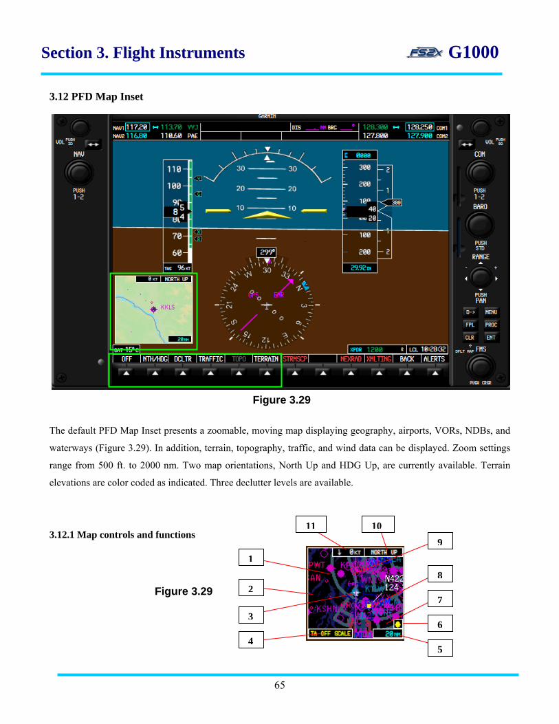
Section 3. Flight Instruments G1000
3.12 PFD Map Inset
Figure 3.29
The default PFD Map Inset presents a zoomable, moving map displaying geography, airports, VORs, NDBs, and
waterways (Figure 3.29). In addition, terrain, topography, traffic, and wind data can be displayed. Zoom settings
range from 500 ft. to 2000 nm. Two map orientations, North Up and HDG Up, are currently available. Terrain
elevations are color coded as indicated. Three declutter levels are available.
3.12.1 Map controls and functions
65
11 109
82
3
45
6
7Figure 3.29
1
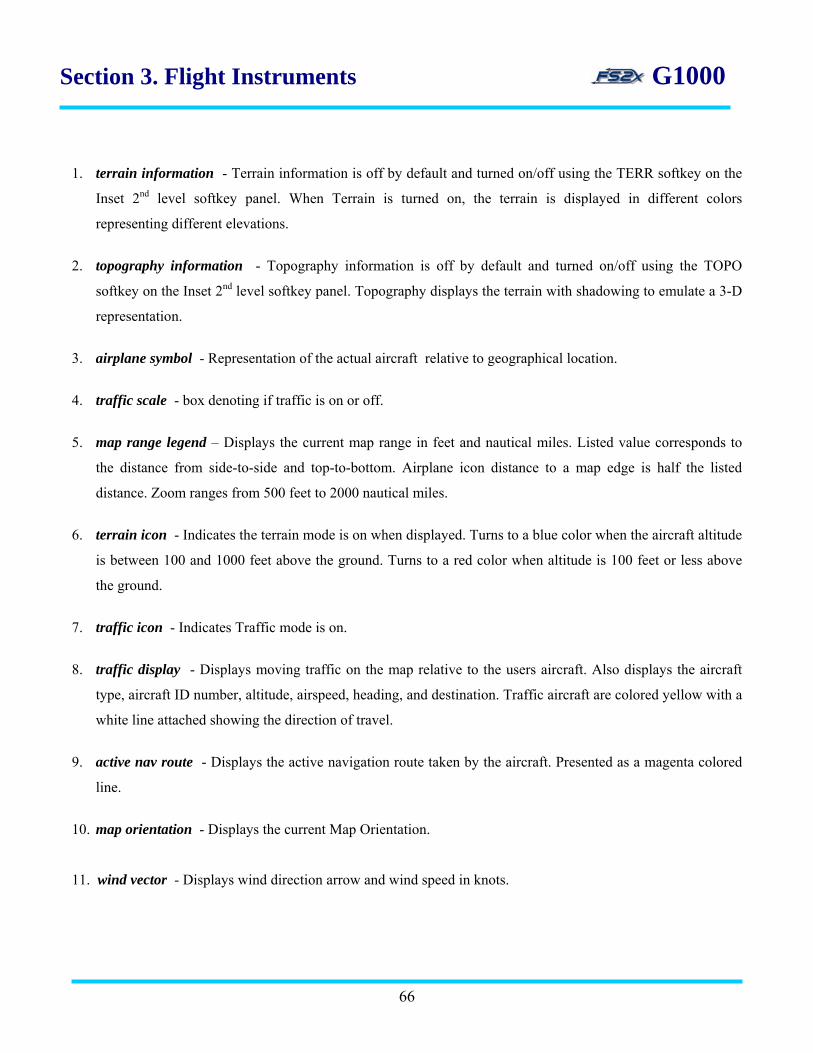
Section 3. Flight Instruments G1000
1. terrain information - Terrain information is off by default and turned on/off using the TERR softkey on the
Inset 2nd level softkey panel. When Terrain is turned on, the terrain is displayed in different colors
representing different elevations.
2. topography information - Topography information is off by default and turned on/off using the TOPO
softkey on the Inset 2nd level softkey panel. Topography displays the terrain with shadowing to emulate a 3-D
representation.
3. airplane symbol - Representation of the actual aircraft relative to geographical location.
4. traffic scale - box denoting if traffic is on or off.
5. map range legend – Displays the current map range in feet and nautical miles. Listed value corresponds to
the distance from side-to-side and top-to-bottom. Airplane icon distance to a map edge is half the listed
distance. Zoom ranges from 500 feet to 2000 nautical miles.
6. terrain icon - Indicates the terrain mode is on when displayed. Turns to a blue color when the aircraft altitude
is between 100 and 1000 feet above the ground. Turns to a red color when altitude is 100 feet or less above
the ground.
7. traffic icon - Indicates Traffic mode is on.
8. traffic display - Displays moving traffic on the map relative to the users aircraft. Also displays the aircraft
type, aircraft ID number, altitude, airspeed, heading, and destination. Traffic aircraft are colored yellow with a
white line attached showing the direction of travel.
9. active nav route - Displays the active navigation route taken by the aircraft. Presented as a magenta colored
line.
10. map orientation - Displays the current Map Orientation.
11. wind vector - Displays wind direction arrow and wind speed in knots.
66

Section 3. Flight Instruments G1000
3.12.2Map instructions
1. click on the INSET softkey located on the main PFD softkey panel to display the map. Clicking on the INSET
softkey also displays the INSET sublevel softkey panel.
2. click on the OFF softkey to close the INSET map.
3. click on the TRAFFIC softkey to display traffic (off by default).
4. click on the DCLTR softkey to cycle through the 3 declutter levels of the INSET map.
5. click on the TOPO softkey to display the map in colored topography.
6. click on the TERR softkey to view the colored topography with shadowing. Topography must be on.
7. click on the NTH/HDG softkey to toggle between a North UP and HDG UP orientation of the map.
8. use the range knob located on the right side of the PFD to change the viewing range of the map.
__________________________________________________________________
.
67

Section 4. Engine Indication System G1000 4. ENGINE INDICATION SYSTEM (EIS)
The G1000 EIS is displayed along the left side of the G1000 MFD during normal operation, and displays a
number of critical engine parameters (see below). The EIS displays this information as round dial gauges,
horizontal bar indicators, bar graphs, and digital readouts. There are 3 information pages available: 1) Engine
Page, 2) Lean Page, and 3) System Page (Figure 4.1). The Engine Page is the default page, and softkeys are used
to toggle between the displays. The torque (TRQ) gauge and the inter turbine temperature (ITT) gauge are
displayed on all 3 pages. Gauges are colored coded to caution and warn of approaching maximum limits.
Engine Page Lean Page System Page
Figure 4.1
68
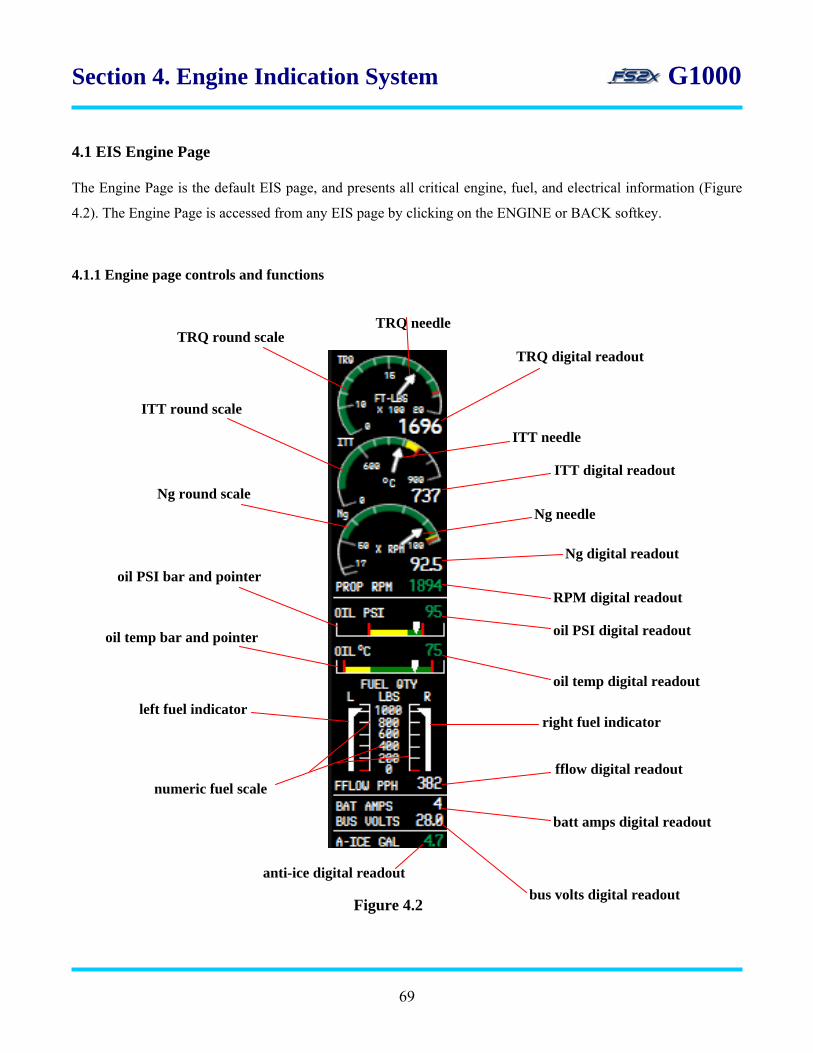
Section 4. Engine Indication System G1000 4.1 EIS Engine Page
The Engine Page is the default EIS page, and presents all critical engine, fuel, and electrical information (Figure
4.2). The Engine Page is accessed from any EIS page by clicking on the ENGINE or BACK softkey.
4.1.1 Engine page controls and functions
Figure 4.2
TRQ round scale
ITT round scale
Ng round scale
oil PSI bar and pointer
oil temp bar and pointer
numeric fuel scale
anti-ice digital readout bus volts digital readout
batt amps digital readout
fflow digital readout
left fuel indicator right fuel indicator
oil temp digital readout
oil PSI digital readout
RPM digital readout
Ng digital readout
ITT digital readout
Ng needle
ITT needle
TRQ digital readout
TRQ needle
69

Section 4. Engine Indication System G1000
1. TRQ needle - the torque needle rotates over the TRQ Round Scale and points to the current torque value.
Torque value denoted by the needle is 1/100 of the actual value, and corresponds to units of foot-pounds.
2. TRQ digital readout - digital display of the current torque in foot-pound units. Color changes from green to
red at the upper limit.
3. ITT needle - the interturbine turbine temperature needle rotates over the ITT Round Scale and points to the
current ITT value. ITT value denoted by the needle is the actual value. Values range from 0-900 degrees
Celsius.
4. ITT digital readout - digital display of the current ITT in degrees Celsius. Color changes from green to
yellow, and then to red when approaching and reaching the upper limits, respectively.
5. Ng needle - the N2 turbine fan speed needle rotates over the Ng Round Scale and points to the current Ng
value. Ng value denoted by the needle is the percentage of the maximum value. Values range from 0-100 %.
6. Ng digital readout - digital display of the current Ng in RPM. Color changes from green to yellow, and then
to red when approaching and reaching the upper limits, respectively.
7. RPM digital readout - digital display of the current propeller speed in RPM. Color changes from green to red
when reaching the upper limits.
8. oil PSI digital readout - displays the current engine oil pressure in pounds per square inch (PSI). Color
changes from green to red at the upper limits.
9. oil temp digital readout - displays the current engine oil temperature in degrees Celsius. Color changes from
green to red at the upper limits.
10. right fuel indicator - displays pounds of fuel currently in the right fuel tank. Presented as a sliding vertical
indicator that slides up and down to denote the fuel quantity. The upper pointer points to the remaining
pounds of fuel on the stationary numeric and vertical scale.
11. fflow digital readout - digital display of the current fuel flow in pounds per hour (PPH).
70

Section 4. Engine Indication System G1000
12. batt amps digital readout - digital display of the main battery load in amperes.
13. bus volts digital readout - digital display of the main bus load in voltage.
14. anti-ice digital readout - digital display of the amount of anti-icing solution available, in gallons.
15. numeric fuel scale – vertical numeric listing and ladder scale used with the fuel indicators to show the
remaining fuel numerically. Values and hash marks presented at 200 pound intervals.
16. left fuel indicator - displays pounds of fuel currently in the left fuel tank. Presented as a sliding vertical
indicator that slides up and down to denote fuel quantity. The upper pointer points to the remaining pounds of
fuel on the stationary numeric and vertical scale.
17. oil temp bar and pointer - presents the current engine oil temperature in degrees Celsius as a horizontal bar
indicator and sliding needle. The needle moves laterally over the stationary bar to denote the current
temperature. Red bars indicate upper and lower limits, and a yellow bay indicates a cautionary range. The
green bar indicates normal operating range.
18. oil PSI bar and pointer - presents the current engine oil pressure in PSI as a horizontal bar indicator and
sliding needle. The needle moves laterally over the stationary bar to denote the PSI value. Red bars indicate
upper and lower limits, and a yellow bay indicates a cautionary range. The green bar indicates normal
operating range.
19. Ng round scale - stationary round scale used by the rotating Ng Needle to indicate the current Ng value in %
RPM. Hash marks are present at 0, 17, and 50%, and then at 10% intervals up to 100%. The yellow and red
bars indicate the cautionary and warning ranges, respectively.
20. ITT round scale - stationary round scale used by the rotating ITT Needle to indicate the current ITT value in
degrees Celsius. Hash marks are present at 0, and 600o, and then at 50o intervals up to 900o. The yellow and
red bars indicate the cautionary and warning ranges, respectively.
21. TRQ round scale - stationary round scale used by the rotating TRQ Needle to indicate the current TRQ value
in degrees Celsius. Values range from 0-20 (x100). Hash marks are present at 0 and 10, and then at 1 ft/lb
(x100 actual) intervals between 10 and 20 ft/lbs. The red bar denotes the upper operating torque.
71

Section 4. Engine Indication System G1000 4.2 EIS Lean Page The Lean Page presents information used for engine leaning (Figure 4.3). It is accessed by clicking on the LEAN
softkey located on the 1st Engine softkey panel. Accessing the Lean Page also provides access to the CYCL SLCT
and ACCESS softkeys located on the 1st Lean softkey panel. In the real world, the CYCL SLCT softkey allows
the user to obtain information from each individual cylinder; however there is no functional distinction between
cylinders in MSFS. Likewise, the ASSIST softkey would be used to identify the EGT peak of each cylinder; but
has no functionality in MSFS.
4.2.1 Lean page controls and functions
Figure 4.3
fflow digital readout
TIT digital readout
EGT peak digital readout
CHT bar graph
CHT digital readout
fuel quantity indicator
EGT digital readout
EGT bar graph
TIT indicator
Figure 4.3
72
Section 4. Engine Indication System G1000
1. fflow digital readout - digital display of the current fuel flow in pounds per hour (PPH).
2. TIT digital readout - digital display of the current turbine inlet temperature in degrees Fahrenheit. Color
changes from white to red at the upper limit.
3. EGT peak digital readout - digital display of the current change in exhaust gas temperature in degrees
Fahrenheit.
4. CHT bar graph - presents cylinder head temperatures in a vertical bar display. Bars are displayed at 50o
intervals from 0 up to a maximum of 500o, with each bar presented immediately above the preceding bar.
Values for individual cylinders have no functional significance in MSFS.
5. CHT digital readout - digital display of the current hottest cylinder head temperature in degrees Fahrenheit.
6. fuel quantity indicator - presents the fuel quantity in the left and right tanks as a stationary horizontal scale
with a moving left and right indicator bug. The indicators move left or right to point to the value on the
horizontal scale. The left tank quantity is defined by the upper indicator and the right tank quantity by the
lower indicator. Indicators are also differentiated by the letter L inside the left indicator, and the letter R
inside the right indicator. Capacity of each tank is 166 gallons.
7. EGT digital readout - digital display of the current hottest EGT in degrees Fahrenheit.
8. EGT bar graph - presents EGT in a vertical bar display. Bars are displayed at 100o intervals from 0 up to a
maximum of 1?00o, with each bar presented immediately above the preceding bar. Values for individual
cylinders have no functional significance in MSFS.
9. TIT indicator - presented as a horizontal bar indicator of the TIT. An indicator bug moves laterally over a
stationary horizontal bar scale to denote the current TIT. The green bar represents the normal operating range,
and the red bar warns that maximum TIT has been reached.
73
Section 4. Engine Indication System G1000
4.2.2 Lean page instructions
The CYCL SLCT softkey can be used to change the ‘selected’ cylinder from white to blue color to emulate real
world functioning. The ACCESS softkey can be used to display the change in EGT from peak value for each
cylinder to emulate real functioning. However, neither emulation has any functional significance in MSFS.
1. click on the ENGINE softkey on the default softkey panel.
2. click on the LEAN softkey on the 1st ENGINE softkey panel.
3. click on the CYCL SLCT softkey to select the desired cylinder. The bars of the chosen cylinder change from
white to blue color.
4. click on the ACCESS softkey to select the desired cylinder. The upper bar of the chosen cylinder will become
open, and the corresponding ∆Peak value is listed in the EGT Peak Digital Readout.
5. click on the BACK softkey to return to higher softkey levels.
4.3 EIS System Page The System Page displays numeric readouts of critical engine, fuel, and electrical data (Figure 4.4). It is
accessed by clicking on the ENGINE softkey on the default softkey panel, and then on the SYSTEM
softkey on the 1st Engine softkey panel. Clicking on the System softkey also brings up the 1st System
softkey panel where the user can change fuel values for calculation purposes. Fuel remaining can be
increased and decreased in 1 or 10 gallon increments, or can be set to the maximum or half-maximum
tank capacity by using softkeys on this panel. Also, fuel remaining and fuel used can be reset to zero at
any time by clicking on the reset button. Fuel values displayed on this page do not use the fuel gauge
indicators, but are calculated from the last time fuel remaining was reset.
74

Section 4. Engine Indication System G1000 4.3.1 System page controls and functions
1. Hobbs meter - displays engine time in hours.* 2. fflow digital readout - digital display of the current fuel flow in gallons per hour (GPH).
3. fuel remaining - fuel remaining in gallon units. Value changed by the user for calculation purposes. 4. essential bus digital readout - digital display of the essential bus load in volts. 5. standby battery digital readout - digital display of the standby battery load in amperes.
fflow digital readout
Hobbs meter
fuel remaining
essential bus digital readout
standby battery digital readout
fuel used
fuel quantity indicator
main bus digital readout
main battery digital readout
Figure 4.4
75

Section 4. Engine Indication System G1000 6. main battery digital readout - digital display of the main battery load in amperes. 7. main bus digital readout - digital display of the main bus load in volts.
8. fuel quantity indicator - defined previously (fuel quantity link). 9. fuel used - digital display of the quantity of fuel used since the Fuel Remaining value was reset to 0. 4.3.2 System page instructions 4.3.2.1 reset Fuel Remaining and Fuel Used to zero 1. click on the ENGINE softkey on the default softkey panel. 2. click on the SYSTEM softkey on the 1st Engine softkey panel. 3. click on RST FUEL softkey. 4. click on the SYSTEM or BACK softkey to return the previous level, or click on one of the other EIS page
softkeys.
4.3.2.2 change FUEL Remaining value 1. click on the ENGINE softkey on the default softkey panel. 2. click on the SYSTEM softkey on the 1st Engine softkey panel. 3. click on the GAL REM softkey. 4. click on the softkey for the desired change. 1) -10 GAL: decrease Fuel Remaining value by 10 gallons. 2) -1 GAL: decrease Fuel Remaining value by 1 gallon. 3) +1 GAL: increase Fuel Remaining value by 1 gallon. 4) +10 GAL: increase Fuel Remaining value by 10 gallons. 3) -166 GAL: set Fuel Remaining value by 166 gallon. 4) +322 GAL: set Fuel Remaining value by 332 gallons. 5. click on the BACK softkey to return to the previous level, or click on one of the other EIS page softkeys.
76

Section 5. MFD Page Groups G1000 5. MFD Page Groups The G1000 MFD Page Group consists of a series of information and data pages grouped together under common
themes to aid the user during GPS navigation. There are 4 main page groups containing a total of 20 sub-pages.
Table 5.1 lists the 4 main page groups and the corresponding sub-pages in the order they are accessed.
CORRESPONDING SUB-PAGESMFD MAIN PAGE GROUPS
Navigation Map Page MAP (MAP) Traffic Map Page Terrain Proximity Map Page
WAYPOINT (WPT) Airport Information Page
Intersection Information Page NDB Information Page VOR Information Page User Waypoint Information
AUXILIARY (AUX) Trip Planning Page Utility Page GPS Status Page System Setup Page System Status Page
NEAREST (NRST) Nearest Airports Page Nearest Intersections Page Nearest NDBs Page Nearest VORs Page Nearest User Waypoints Page Nearest Frequencies Page Nearest Airspaces Page
Table 5.1
77

Section 5. MFD Page Groups G1000
The MFD Page Group pages are displayed in a window along the right side of the MFD display screen (Figure
5.1). They are accessed and changed using the dual FMS Knob. The active page group and corresponding page
title are displayed in the Page Title Window. The selected page group and selected sub-page are displayed in the
Page Group Window.
page title window
MFD Page Group window dual FMS knobpage group window
page groups
selected sub-page
sub-pages in current group
selected page groupactive page group active page title
Figure 5.1
78

Section 5. MFD Page Groups G1000
1. page title window - lists the active Page Group and active Page Group Title.
2. dual FMS knob - used to scroll through the main page groups (upper click areas), and the sub-page group
pages (lower click areas). Also used to change variables within the active main group/sub-page choice. In
general, the large FMS knob (upper click areas) is used to scroll between choice fields, and the small FMS
knob (lower click areas) is used to change the variable within the field.
3. page group window - displays the available main page groups, and the main page group selected. Also lists
the number of sub-pages in the selected main group, and identifies the selected sub-page.
4. MFD Page Group window - popup window displaying the information and data corresponding to the active
main group/sub- page.
5. active page group - denotes active main page group (abbreviation).
6. active page title - displays the title of the active main page group.
7. page groups - lists the 4 available main page group choices.
8. sub-pages in current group - shows the number of sub-pages in the selected main page group as open white
boxes.
9. selected page group - the selected main page group is denoted by a bright cyan coloring of the selected
group.
10. selected sub-page - the selected sub-page is denoted by a cyan colored fill-in of the corresponding open
white box.
79

Section 5. MFD Page Groups G1000
5.1 MFD Map Page Group
5.1.1 Navigation Map Page
The Navigation Map Page is the first page in the Map Page Group and is accessed from the default page by
clicking on the large FMS knob. The Navigation Map Page is capable of displaying the following GPS
Navigation information:
map display showing airports, land data, NAVAIDS, and airspaces with names
bearing and distance to any location from any location
map range
wind direction and speed
heading information
aircraft icon
map feature icons
tracking vector
topography data and scale
fuel range ring
airways
The information displayed on the Navigation Map Page can be customized using the Navigation Map Page Menu
(Figure 5.2). The Navigation Map Page Menu is accessed from the Navigation Map Page by clicking on the
MENU. There are three Nav Map page menu options:
1: map setup
2: declutter
3: measure bearing/distance
Figure 5.2
80

Section 5. MFD Page Groups G1000 5.1.1.1 Map Setup
The Map Setup option is used to change how and/or when GPS navigation information is displayed on
the map. It is accessed from the Nav Map Page Menu Window by clicking on the ENTER button when the Map
Setup field is highlighted. Within the Map Setup option, information is grouped into six Map Setup
Groups (Figure 5.3).
1: map group
2: weather group
3: traffic group
4: aviation group
5: airways group
6: land group
map setup group window
Figure 5.3
5.1.1.1.1 map setup map group
The Map Setup Map Group page is used to change the map orientation, and to turn on and off certain data
displays (Figure 5.4). It is accessed from the Map Setup Group Window by clicking on the ENTER softkey when
the Map field is highlighted.
81

Section 5. MFD Page Groups G1000
Figure 5.4
1. orientation - use this function to select the map orientation. The Map Orientation Window is displayed when
this field is chosen (Figure 5.5). The choice is displayed in the Orientation field. There are four choices:
1: North up - fixes top of map display to a north heading.
2: Track up - fixes top of map display to the current ground track.*
3: DTK up - fixes top of map display to the desired course.*
4: HDG up - fixes top of map to the current aircraft heading.
(*note: only North Up and Hdg Up currently available)
map orientation window Map orientation field
Figure 5.5
82
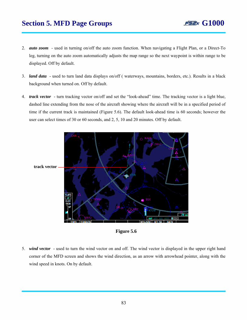
Section 5. MFD Page Groups G1000
2. auto zoom - used in turning on/off the auto zoom function. When navigating a Flight Plan, or a Direct-To
leg, turning on the auto zoom automatically adjusts the map range so the next waypoint is within range to be
displayed. Off by default.
3. land data - used to turn land data displays on/off ( waterways, mountains, borders, etc.). Results in a black
background when turned on. Off by default.
4. track vector - turn tracking vector on/off and set the “look-ahead” time. The tracking vector is a light blue,
dashed line extending from the nose of the aircraft showing where the aircraft will be in a specified period of
time if the current track is maintained (Figure 5.6). The default look-ahead time is 60 seconds; however the
user can select times of 30 or 60 seconds, and 2, 5, 10 and 20 minutes. Off by default.
track vector
Figure 5.6
5. wind vector - used to turn the wind vector on and off. The wind vector is displayed in the upper right hand
corner of the MFD screen and shows the wind direction, as an arrow with arrowhead pointer, along with the
wind speed in knots. On by default.
83
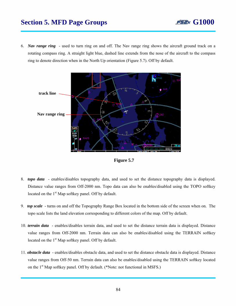
Section 5. MFD Page Groups G1000
6. Nav range ring - used to turn ring on and off. The Nav range ring shows the aircraft ground track on a
rotating compass ring. A straight light blue, dashed line extends from the nose of the aircraft to the compass
ring to denote direction when in the North Up orientation (Figure 5.7). Off by default.
track line
Nav range ring
Figure 5.7
Figure 5.7
8. topo data - enables/disables topography data, and used to set the distance topography data is displayed.
Distance value ranges from Off-2000 nm. Topo data can also be enables/disabled using the TOPO softkey
located on the 1st Map softkey panel. Off by default.
9. top scale - turns on and off the Topography Range Box located in the bottom side of the screen when on. The
topo scale lists the land elevation corresponding to different colors of the map. Off by default.
10. terrain data - enables/disables terrain data, and used to set the distance terrain data is displayed. Distance
value ranges from Off-2000 nm. Terrain data can also be enables/disabled using the TERRAIN softkey
located on the 1st Map softkey panel. Off by default.
11. obstacle data - enables/disables obstacle data, and used to set the distance obstacle data is displayed. Distance
value ranges from Off-50 nm. Terrain data can also be enables/disabled using the TERRAIN softkey located
on the 1st Map softkey panel. Off by default. (*Note: not functional in MSFS.)
84

Section 5. MFD Page Groups G1000 12. fuel range (rsv) - turns the fuel range ring on/off, and displays the time of flight remaining with the current
fuel usage. The fuel range ring is displayed as a green circle and shows the distance the aircraft can fly with
the remaining fuel at the current fuel usage. Distance is defined as the distance from the aircraft icon to the
range ring. Off by default. . (*Note: not currently functional in the fs2x G1000.)
Instructions for using the Map Group Page
1. go to the Navigation Map Page by clicking on the large FMS knob. When on the Navigation Map
Page, the page title (MAP – Navigation Map) will be listed in the Page Title Window, the MAP
lettering in the Page Group Window will be highlighted, and the first rectangular box will be filled.
2. click on the MENU button to call up the Navigation Map Page Menu Window. The first choice, MAP
SETUP, will be highlighted. Click on the MENU button again at any time the menu is displayed to
remove it.
3. use the large FMS knob to scroll the cursor (highlighting and blinking) up and down through the
choices. When the desired choice is highlighted, click on the ENTER button to go to that page.
4. 1 map setup page
1. click on the ENTER button when MAP SETUP is highlighted on the Navigation Map Page Menu.
This will display the Map Setup Page Window with the Map Page Group choices showing.
2. use the small FMS knob to scroll the cursor up and down through the Map Page Group choices.
When the desired choice is highlighted, click on the ENTER button to go to that page.
3.1 map setup page MAP GROUP
1. click on the ENTER button when the MAP field of the Map Setup Page Window is highlighted to
display the Map Group page.
2. use the large FMS knob to scoll the blinking cursor up and down through the different data fields.
3. when the field to be changed is highlighted, use the small FMS knob to change the value. For on/off
choices, click on the side of the small FMS button denoted by the highlighted light green arrowhead
85

Section 5. MFD Page Groups G1000
to change the value. For numerical value changes use the small FMS knob right click spot to
increase the value, and the left spot to decrease the value.
4. when the Map Orientation Field is highlighted, the Map Orientation Window (Figure 5.5) is
displayed. Use the small FMS knob to scroll through the choices. With the desired choice
highlighted, click on the ENTER button to enter the choice. Clicking on the large FMS knob will
scroll the cursor to the next data field without entering the choice, and the Map Orientation Window
will be removed.
5.1.1.1.2 map setup weather group
1. NO WEATHER EQUIPMENT INSTALLED ON THIS AIRCRAFT. Space reserved for future
weather information.
5.1.1.1.3 map setup traffic group
Figure 5.8
The Map Setup Traffic Group page is used to turn the traffic display on/off, choose what traffic is displayed, and
the distance from the aircraft that traffic symbols and labels are displayed (Figure 5.8).
86
Section 5. MFD Page Groups G1000
1. traffic - toggles the traffic display on/off. Performs the same function as the TRAFFIC softkey
located on the 1st level MAP softkey panel.
2. traffic mode - allows the user to choose different traffic displays on the MFD screen. Choices are: 1)
All Traffic, 2) Traffic and Proximity Advisories, and 3) Traffic Advisories Only. Currently no
functional significance in the fs2x G1000.
3. traffic smbl - used to set the distance from the aircraft that traffic symbols are displayed on the MFD
screen. Values range from 0-2000nm.*
4. traffic lbl - used to set the distance from the aircraft that traffic labels are displayed on the MFD
screen. Values range from 0-2000nm. *
Instructions for using the Traffic Group Page
1. follow the “Instructions for using the Map Group Page” and “Map Setup Page” instructions above to display
the Navigation Map Page Menu.
2. use the large FMS knob to scoll the blinking cursor up or down to highlight the TRAFFIC field.
3. click on the ENTER button when TRAFFIC is highlighted on the Navigation Map Page Menu. This will
display the Map Setup Page Window with the Traffic Page Group choices showing.
4. use the large FMS knob to scoll the blinking cursor up and down through the different data fields.
5. when the field to be changed is highlighted, use the small FMS knob to change the value.
5.1 click on the side of the small FMS knob denoted by the highlighted light green arrowhead in the
traffic field to turn the traffic display on/off.
5.2 use the small FMS knob to scroll the blinking cursor through the different traffic mode.
5.3 use the small FMS knob right click spot to increase traffic symbol and label distance values, and the
left spot to decrease distance values.
87
6. click on the ENTER button to return to the Navigation Map Page Menu page, or click on the FMS knob to
return to the Navigation Map Page.
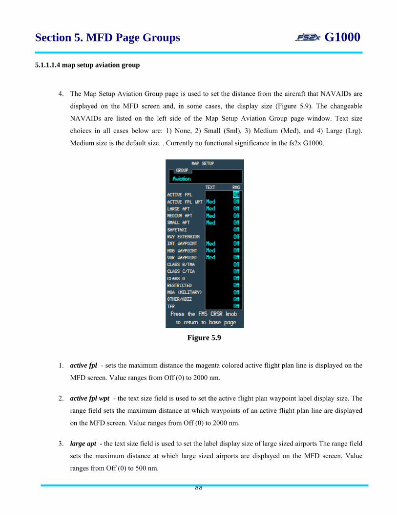
Section 5. MFD Page Groups G1000 5.1.1.1.4 map setup aviation group
4. The Map Setup Aviation Group page is used to set the distance from the aircraft that NAVAIDs are
displayed on the MFD screen and, in some cases, the display size (Figure 5.9). The changeable
NAVAIDs are listed on the left side of the Map Setup Aviation Group page window. Text size
choices in all cases below are: 1) None, 2) Small (Sml), 3) Medium (Med), and 4) Large (Lrg).
Medium size is the default size. . Currently no functional significance in the fs2x G1000.
Figure 5.9
1. active fpl - sets the maximum distance the magenta colored active flight plan line is displayed on the
MFD screen. Value ranges from Off (0) to 2000 nm.
2. active fpl wpt - the text size field is used to set the active flight plan waypoint label display size. The
range field sets the maximum distance at which waypoints of an active flight plan line are displayed
on the MFD screen. Value ranges from Off (0) to 2000 nm.
3. large apt - the text size field is used to set the label display size of large sized airports The range field
sets the maximum distance at which large sized airports are displayed on the MFD screen. Value
ranges from Off (0) to 500 nm.
88
Section 5. MFD Page Groups G1000 4. medium apt - the text size field is used to set the label display size of medium sized airports. The range field
sets the maximum distance at which medium sized airports are displayed on the MFD screen. Value ranges
from Off (0) to 300 nm.
5. small apt - the text size field is used to set the label display size of small sized airports. The range field sets
the maximum distance at which small sized airports are displayed on the MFD screen. Value ranges from Off
(0) to 100 nm.
6. safetaxi - sets the maximum distance at which the safetaxi function is displayed on the MFD screen. Value
ranges from Off (0) to 2000 nm.
7. rwy extension - sets the maximum distance runway extension lines drawn through the runway centerline for
situational awareness are displayed on the MFD screen. Value ranges from Off (0) to 100 nm.
8. int waypoint - the text size field is used to set the label display size of Intersection NAVAIDs. The range field
sets the maximum distance at which Intersection NAVAIDs are displayed on the MFD screen. Value ranges from
Off (0) to 30 nm.
9. ndb waypoint - the text size field is used to set the label display size of NDB NAVAIDs. The range field sets
the maximum distance at which NDB NAVAIDs are displayed on the MFD screen. Value ranges from Off (0) to
30 nm.
10. vor waypoint - the text size field is used to set the label display size of VOR NAVAIDs. The range field sets
the maximum distance at which VOR NAVAIDs are displayed on the MFD screen. Value ranges from Off (0)
to 300 nm.
11. class B/TMA - sets the maximum distance Class B/TMA airport labels are displayed on the MFD screen.
Value ranges from Off (0) to 500 nm.
12. class C/TMA - sets the maximum distance Class C/TMA airport labels are displayed on the MFD screen.
Value ranges from Off (0) to 500 nm.
13. class D - sets the maximum distance Class D airport labels are displayed on the MFD screen. Value ranges
from Off (0) to 300 nm.
14. restricted - sets the maximum distance Restricted Area labels are displayed on the MFD screen. Value ranges
from Off (0) to 500 nm.
89

Section 5. MFD Page Groups G1000
15. MOA (military) - sets the maximum distance Military Operations labels are displayed on the MFD screen.
Value ranges from Off (0) to 500 nm.
16. other/ADIZ - sets the maximum distance Other/ADIZ (training, caution, danger, warning, and alert areas) are
displayed on the MFD screen. Value ranges from Off (0) to 500 nm.
17. TFR - sets the maximum distance Temporary Flight Restriction labels are displayed on the MFD screen.
Value ranges from Off (0) to 2000 nm.
Instructions for using the Aviation Group Page
1. follow the “Instructions for using the Map Group Page” and “Map Setup Page” instructions above (link) to
display the Navigation Map Page Menu.
2. use the large FMS knob to scoll the blinking cursor up or down to highlight the AVIATION field.
3. click on the ENTER button when AVIATION is highlighted on the Navigation Map Page Menu. This will
display the Aviation Setup Page Window with the Aviation Group Page choices showing.
4. use the large FMS knob to scoll the blinking cursor up and down through the different data fields.
5. when the field to be changed is highlighted, use the small FMS knob to change the value.
5.1 click the small FMS knob when the chosen field is highlighted to change the display distance in the
distance fields. Values are increased by clicking on the lower right click spot, and decreased by clicking
on the left click spot.
5.2 use the small FMS knob to scroll through the text size choices when the corresponding field is
highlighted.
6. click on the ENTER button to return to the Map Setup Group Window, or click on the FMS knob to
return to the Navigation Map Page.
90
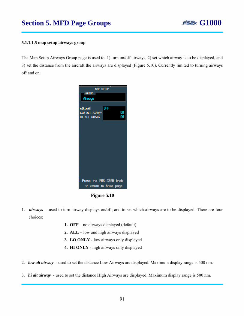
Section 5. MFD Page Groups G1000
5.1.1.1.5 map setup airways group
The Map Setup Airways Group page is used to, 1) turn on/off airways, 2) set which airway is to be displayed, and
3) set the distance from the aircraft the airways are displayed (Figure 5.10). Currently limited to turning airways
off and on.
1. airways - used to turn airway displays on/off, and to set which airways are to be displayed. There are four
choices:
1. OFF – no airways displayed (default)
2. ALL – low and high airways displayed
3. LO ONLY - low airways only displayed
4. HI ONLY - high airways only displayed
2. low alt airway - used to set the distance Low Airways are displayed. Maximum display range is 500 nm.
3. hi alt airway - used to set the distance High Airways are displayed. Maximum display range is 500 nm.
Figure 5.10
91

Section 5. MFD Page Groups G1000
Instructions for using the Airways Group Page
1. follow the “Instructions for using the Map Group Page” and “Map Setup Page” instructions above to display
the Navigation Map Page Menu.
2. use the large FMS knob to scoll the blinking cursor up or down to highlight the AIRWAYS field.
3. click on the ENTER button when AIRWAYS is highlighted on the Navigation Map Page Menu. This will
display the Airways Setup Page Window with the Airways Group Page choices showing.
4. use the large FMS knob to scoll the blinking cursor up and down through the different data fields.
5. when the field to be changed is highlighted, use the small FMS knob to change the value.
5.1 use the small FMS knob to scroll through the airways display choices when the Airways field is
highlighted.
5.2 use the small FMS knob to change the distance for the corresponding airway to be displayed when the
LO or HI AIRWAYS field is highlighted .
6. click on the ENTER button to return to the Map Setup Group Window, or click on the FMS knob to
return to the Navigation Map Page.
5.1.1.1.6 map setup land group
The Map Setup Land Group page is used to set the text size of certain land features, and to specify the distance
land features are displayed (Figure 5.11). Text size choices in all cases below are: 1) None, 2) Small (Sml), 3)
Medium (Med), and 4) Large (Lrg). Medium size is the default size. Maximum display ranges are denoted below.
All fields are currently non-functional in the fs2x G1000, but are displayed for future usage.
92
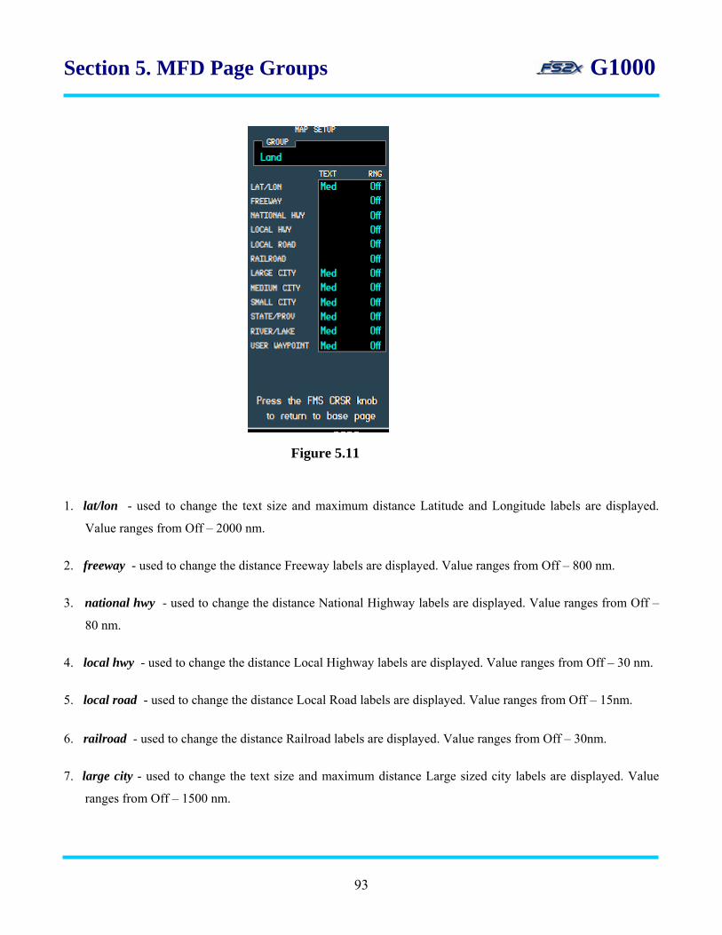
Section 5. MFD Page Groups G1000
1. lat/lon - used to change the text size and maximum distance Latitude and Longitude labels are displayed.
Value ranges from Off – 2000 nm.
2. freeway - used to change the distance Freeway labels are displayed. Value ranges from Off – 800 nm.
3. national hwy - used to change the distance National Highway labels are displayed. Value ranges from Off –
80 nm.
4. local hwy - used to change the distance Local Highway labels are displayed. Value ranges from Off – 30 nm.
5. local road - used to change the distance Local Road labels are displayed. Value ranges from Off – 15nm.
6. railroad - used to change the distance Railroad labels are displayed. Value ranges from Off – 30nm.
7. large city - used to change the text size and maximum distance Large sized city labels are displayed. Value
ranges from Off – 1500 nm.
Figure 5.11
93

Section 5. MFD Page Groups G1000
8. medium city - used to change the text size and maximum distance Medium sized city labels are displayed.
Value ranges from Off – 200 nm.
9. small city - used to change the text size and maximum distance Small city labels are displayed. Value ranges
from Off – 50 nm.
10. state/prov - used to change the text size and maximum distance State and Province labels are displayed. Value
ranges from Off – 1500 nm.
11. river/lake - used to change the text size and maximum distance River and Lake labels are displayed. Value
ranges from Off –500 nm.
12. user waypoint - used to change the text size and maximum distance User Waypoint labels are displayed.
Value ranges from Off – 300 nm.
Instructions for using the Land Group Page
1. follow the “Instructions for using the Map Group Page” and “Map Setup Page” instructions above (link) to
display the Navigation Map Page Menu.
2. use the large FMS knob to scoll the blinking cursor up or down to highlight the AVIATION field.
3. click on the ENTER button when AVIATION is highlighted on the Navigation Map Page Menu. This will
display the Aviation Setup Page Window with the Aviation Group Page choices showing.
4. use the large FMS knob to scoll the blinking cursor up and down through the different data fields.
5. when the field to be changed is highlighted, use the small FMS knob to change the value.
5.1 use the small FMS knob to scroll through the text size choices when the corresponding field is
highlighted.
5.2 click the small FMS knob when the chosen field is highlighted to change the display distance in the
distance fields. Values are increased by clicking on the lower right click spot, and decreased by clicking
on the lower left click spot.
94

Section 5. MFD Page Groups G1000
6. click on the ENTER button to return to the Map Setup Group Window, or click on the FMS knob to
return to the Navigation Map Page.
5.1.1.2 Declutter
The Declutter field in the Map Page Menu Window is used to progressively remove groups of information from
the display screen at the same time (Figure 5.12). It is used to select the desired amount of map detail. The
declutter level (DCLTR- #) is displayed on the right side of the Declutter field unless the level is 0 (no declutter
and no display). The default display is no declutter. The same function can be performed using the DCLTR
softkey on the main MFD softkey panel.
declutter field
declutter level
Figure 5.2
There are 4 Declutter levels to choose from:
1. DCLTR (no declutter) – all map details and features are visible.
2. DCLTR-1 - land data removed.
3. DCLTR-2 - land and SUA (Special Use Airspace) data removed.
4. DCLTR-3 - all map details and features except an active flight plan are removed.
Table 5.2 lists the data/feature displays that are turned off at each declutter level, and those not removed at any
level. The “X”s denotes that the corresponding Data/Features are not displayed at the corresponding declutter
level listed at the top. The dashed lines divide the Data/Features into the separate declutter levels.
95
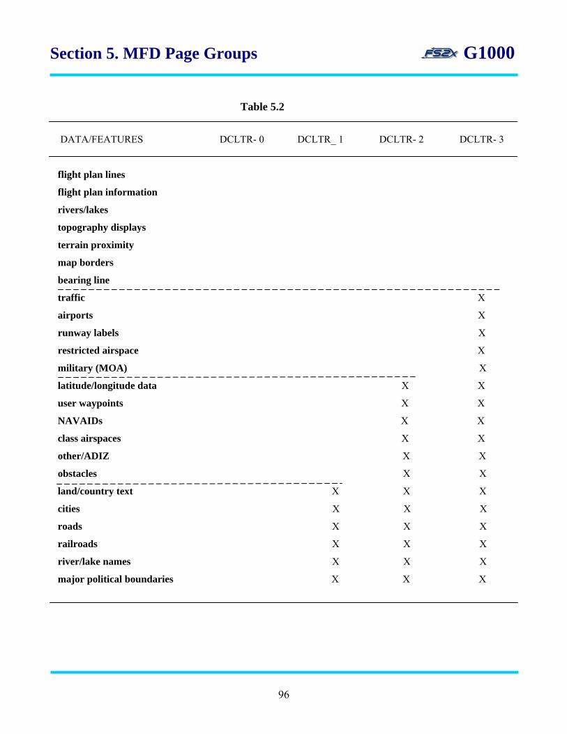
Section 5. MFD Page Groups G1000
Table 5.2
DATA/FEATURES DCLTR- 0 DCLTR_ 1 DCLTR- 2 DCLTR- 3 flight plan lines
flight plan information
rivers/lakes
topography displays
terrain proximity
map borders
bearing line
traffic X
airports X
runway labels X
restricted airspace X
military (MOA) X
latitude/longitude data X X
user waypoints X X
NAVAIDs X X
class airspaces X X
other/ADIZ X X
obstacles X X
land/country text X X X
cities X X X
roads X X X
railroads X X X
river/lake names X X X
major political boundaries X X X
96
Section 5. MFD Page Groups G1000
Instructions for using the declutter function
1. follow the “Instructions for using the Map Group Page” instructions above to display the Map Setup Page.
2. use the large FMS knob to scoll the blinking cursor up or down to highlight the Declutter field.
3. click on the ENTER button with the Declutter field highlighted to change the declutter level. Each successive
click on the ENTER button increases the declutter level and removes more data/features. Clicking on the
ENTER button on level 3 (DCLTR- 3) will cycle the level back to 0 (no declutter).
5.1.1.2 Measure Bearing/Distance
The Measure Bearing/Distance Page is the third and last page of the Navigation Map Page Group (Figure 5.13).
This page allows the user to determine the distance and bearing from any point on the earth to any other point on
the earth. (This page is not the same as in the real world Garmin G1000, but was designed to replace the MAP
PANNING feature where determining the bearing and distance between any 2 points is performed using ‘joystick
panning’.) Data can be entered as an ICAO for 1) airports, 2) intersections, 3) NDBs, 4) VORs, or entered directly
as 5) latitude/longitude. All combinations between points are possible (ex., VOR<-->APT, VOR<-->VOR, etc.).
A ‘point A <--> point B’ softkey on the MAP 1st softkey panel (A-B) toggles between the 2 points for data entry.
There are 6 data entry fields for each point:
1. APT ICAO – airport ICAO
2. INT ICAO – intersection ICAO
3. NDB ICAO – NDB ICAO
4. VOR ICAO – VOR ICAO
5. latitude – latitude in degrees, minutes, seconds format
6. longitude – longitude in degrees, minutes, seconds format
97

Section 5. MFD Page Groups G1000 Pt.A data field
1. pt.A data field - upper section of the window displaying data fields corresponding to Point A.
2. bearing display - displays the Great Circle magnetic bearing from point A to point B in degrees.
3. data field denotation - denotes the active data field for data entry (Point A or Point B). The active data field is
displayed in cyan, the inactive data field in white.
4. pt.A selection box - light gray box denoting the selected field. Cycles through all 6 Point A data entry fields.
5. pt.B ICAO name display - displays the point B name corresponding to the entered ICAO code. LAT/LON
POS is displayed instead if the selected point is defined by latitude and longitude.
6. pt.B selection box - light gray box denoting the selected field. Cycles through all 6 Point B data entry fields.
7. pt.B data field - upper section of the window displaying data fields corresponding to Point B.
Figure 5.13
bearing display distance display
Pt.A ICAO display
Pt.A ICAO name display Pt.A selection box
Pt.A lat/lon display
Pt.B selection box
Pt.B ICAO name display Pt.B ICAO display
Pt.B lat/lon display
data field denotation
Pt.B data field
98

Section 5. MFD Page Groups G1000
8. pt.B lat/lon display - displays the Point B latitude/longitude field values. Used to change latitude and
longitude values when selected.
9. pt.B ICAO display - displays the entered Point B ICAO code. LAT/LON POS is displayed instead if the
selected point is defined by latitude and longitude.
10. pt.A lat/lon display - displays the Point A latitude/longitude field values. Used to change latitude and
longitude values when selected.
11. pt.A ICAO name display - displays the point A name corresponding to the entered ICAO code. LAT/LON
POS is displayed instead if the selected point is defined by latitude and longitude.
12. pt.A ICAO display - displays the entered Point A ICAO code. LAT/LON POS is displayed instead if the
selected point is defined by latitude and longitude.
13. distance display - displays the Great Circle distance from point A to point B in nautical miles.
Instructions for using the measure bearing/distance page
1. follow the “Instructions for using the Map Group Page” instructions above to display the Navigation Map Page
Menu.
2. use the large FMS knob to scroll the blinking cursor up or down to highlight the Measure Bearing/Distance
field.
3. click on the ENTER button to open the Measure Bearing/Distance Window (Figure 5.13).
4. click on the A-B softkey located on the MAP 1st softkey panel to select between Point A and Point B for data
entry.
5. use the large FMS knob to scroll the point selection box to one of the 6 data entry fields.
6. click on the FMS knob. The corresponding ICAO display will be highlighted with a blinking cursor if
the selection is one of the first 4 data entry fields. The first digit of the latitude or longitude data field
will be highlighted instead if either field is selected.
99
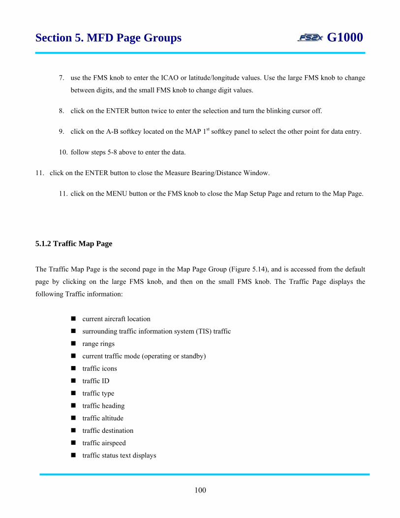
Section 5. MFD Page Groups G1000
7. use the FMS knob to enter the ICAO or latitude/longitude values. Use the large FMS knob to change
between digits, and the small FMS knob to change digit values.
8. click on the ENTER button twice to enter the selection and turn the blinking cursor off.
9. click on the A-B softkey located on the MAP 1st softkey panel to select the other point for data entry.
10. follow steps 5-8 above to enter the data.
11. click on the ENTER button to close the Measure Bearing/Distance Window.
11. click on the MENU button or the FMS knob to close the Map Setup Page and return to the Map Page.
5.1.2 Traffic Map Page
The Traffic Map Page is the second page in the Map Page Group (Figure 5.14), and is accessed from the default
page by clicking on the large FMS knob, and then on the small FMS knob. The Traffic Page displays the
following Traffic information:
current aircraft location
surrounding traffic information system (TIS) traffic
range rings
current traffic mode (operating or standby)
traffic icons
traffic ID
traffic type
traffic heading
traffic altitude
traffic destination
traffic airspeed
traffic status text displays
100
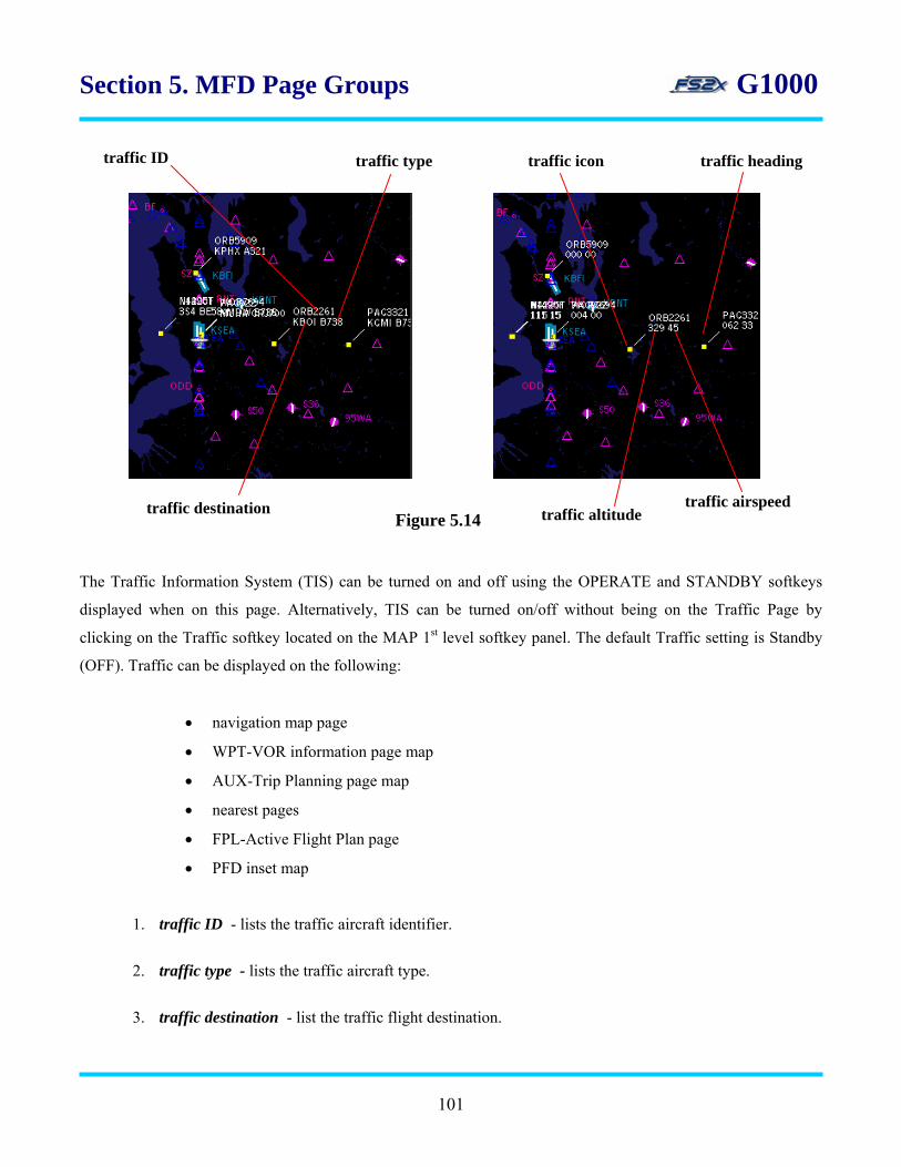
Section 5. MFD Page Groups G1000
traffic ID
The Traffic Information System (TIS) can be turned on and off using the OPERATE and STANDBY softkeys
displayed when on this page. Alternatively, TIS can be turned on/off without being on the Traffic Page by
clicking on the Traffic softkey located on the MAP 1st level softkey panel. The default Traffic setting is Standby
(OFF). Traffic can be displayed on the following:
• navigation map page
• WPT-VOR information page map
• AUX-Trip Planning page map
• nearest pages
• FPL-Active Flight Plan page
• PFD inset map
1. traffic ID - lists the traffic aircraft identifier.
2. traffic type - lists the traffic aircraft type.
3. traffic destination - list the traffic flight destination.
Figure 5.14
traffic type
traffic destination traffic altitude traffic airspeed
traffic icon traffic heading
101

Section 5. MFD Page Groups G1000
4. traffic icon - square, yellow icon display representing traffic aircraft.
5. traffic heading - ‘heading tail’ indicating the traffic aircraft heading. Shows the track the traffic
aircraft is traveling.
6. traffic airspeed - lists the traffic aircraft airspeed in knots (/10).
7. traffic altitude - list the traffic aircraft altitude in feet ASL (/100).
Instructions for using the traffic page
1. click on the large FMS knob to go to the Map Page Group. The first rectangle in the ??? box will be filled
with blue.
2. click on the small FMS knob to scroll to the Traffic Page. The second rectangle will fill with blue. STANDBY
and OPERATE softkeys will be displayed on the softkey panel.
3. click on the STANDBY or OPERATE softkey to turn traffic off or on, respectively.
5.1.3 Terrain Proximity Map Page
The Terrain Proximity Map Page is the third and last page in the Map Page Group, and is accessed from the
default page by clicking on the large and small FMS knobs. Terrain can also be accessed from the MAP 1st level
TERRAIN softkey. The Terrain Proximity Map Page is currently non-functional in the fs2x G1000. However, in
the real world the Garmin G100 displays the following terrain information:
current aircraft location
GPS-derived MSL altitude
range marking rings
heading box
terrain
terrain range
102
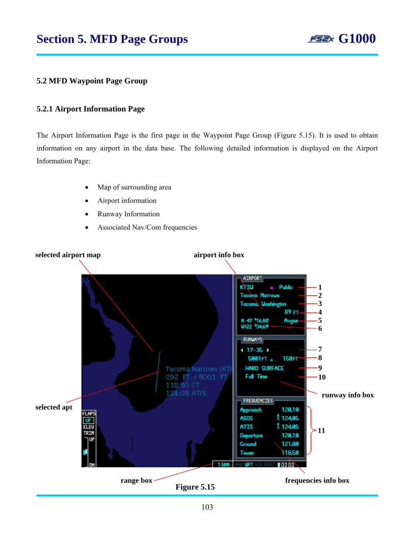
Section 5. MFD Page Groups G1000
5.2 MFD Waypoint Page Group
5.2.1 Airport Information Page
The Airport Information Page is the first page in the Waypoint Page Group (Figure 5.15). It is used to obtain
information on any airport in the data base. The following detailed information is displayed on the Airport
Information Page:
• Map of surrounding area
• Airport information
• Runway Information
• Associated Nav/Com frequencies
selected airport map airport info box
Figure 5.15
runway info box
frequencies info box range box
1 2 3 4 5 6
7 8 9 10
selected apt
11
103
Section 5. MFD Page Groups G1000
1. airport info box - identifies the selected airport by ICAO code, airport name, city name, and
laltitude/longitude coordinates. Also lists airport elevation (MSL) and available gas type.
2. runway info box - displays selected runway and lists information pertinent to the selected runway.
3. frequencies info box - scrollable box listing available navigation and communications frequencies at
the selected airport.
4. range box - displays the map range in nm. Map range for this page can be changed by the user.
5. selected apt map display - map display of the selected airport.
6. line 1 - lists the selected airport ICAO, the airport type symbol, and the airport classification.
7. line 2 - lists the selected airport name.
8. line 3 - lists the selected airport city name.
9. line 4 - lists the selected airport altitude (MSL).
10. line 5 - lists the types of gas available at the selected airport.
11. line 6 - lists the latitude and longitude coordinates of the selected airport.
12. line 7 - lists the runways at the selected airport.
13. line 8 - lists the selected runway length and width.
14. line 9 - lists the selected runway surface type.
15. line 10 - lists the selected airport runway lighting.
16. line 11 – nav/com frequencies list for the selected airport.
104

Section 5. MFD Page Groups G1000
Instructions for using the airport information page
1. click on the large FMS to go to the Waypoint Page Group. The text ‘WPT’ in the Page Group Window will be
highlighted.
2. use the small FMS knob to go to the Airport Information Page. The first rectangle in the Page Group Window
will be filled in blue.
3. click on the FMS knob to activate the blinking cursor. The blinking cursor will highlight the ICAO field in
preparation for a new airport selection. To change the ICAO code, follow steps 3.1 – 3.3.
3.1 with the ICAO field highlighted, click on the small FMS knob to highlight the first ICAO code letter.
3.2 use the small FMS knob, or computer keyboard, to enter the desired ICAO code.
3.3 click on the ENTER button to accept the selection. The ICAO code will be highlighted.
4. use the large FMS knob to scroll the blinking cursor to the Airport Name field. To change the selected airport
by Airport Name, follow steps 4.1 – 4.3.
4.1 with the Airport Name field highlighted, click on the small FMS knob to highlight the first airport
letter.
4.2 use the small FMS knob, or computer keyboard, to enter the desired Airport Name.
4.3 click on the ENTER button to accept the selection. The Airport Name will be highlighted.
5. use the large FMS knob to scroll the blinking cursor to the Runway Designation field.
5.1 with the Runway Designation field highlighted, click on the small FMS knob to scroll through the
airport runway list. Click on the right small FMS knob to scroll right, and the left small FMS knob to
scroll left. The Runway Designation field will be highlighted. The green arrowheads are dark if no
other runways exist at the airport, otherwise the light green arrowhead denotes which side of the small
FMS to click to view another runway.
6. use the large FMS knob to scroll the blinking cursor to the first Frequencies field.
105
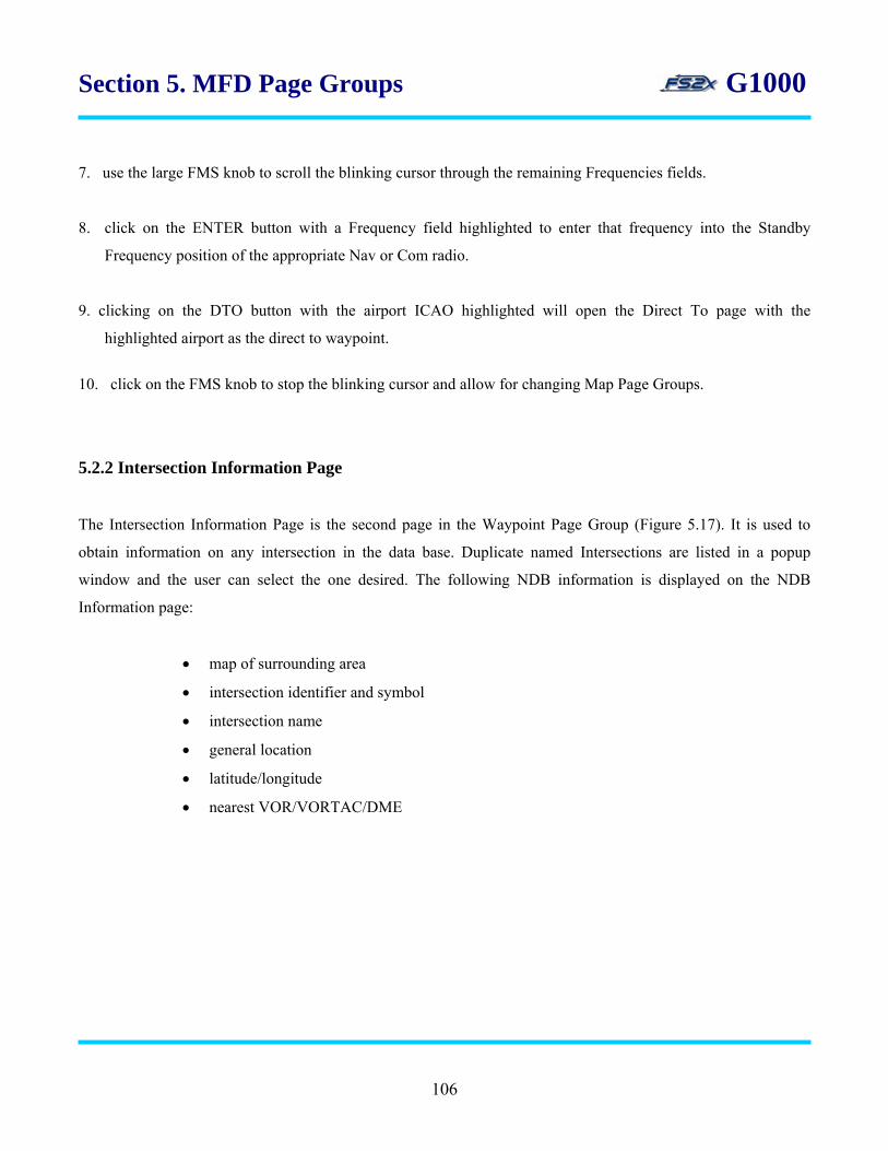
Section 5. MFD Page Groups G1000
7. use the large FMS knob to scroll the blinking cursor through the remaining Frequencies fields.
8. click on the ENTER button with a Frequency field highlighted to enter that frequency into the Standby
Frequency position of the appropriate Nav or Com radio.
9. clicking on the DTO button with the airport ICAO highlighted will open the Direct To page with the
highlighted airport as the direct to waypoint.
10. click on the FMS knob to stop the blinking cursor and allow for changing Map Page Groups.
5.2.2 Intersection Information Page
The Intersection Information Page is the second page in the Waypoint Page Group (Figure 5.17). It is used to
obtain information on any intersection in the data base. Duplicate named Intersections are listed in a popup
window and the user can select the one desired. The following NDB information is displayed on the NDB
Information page:
• map of surrounding area
• intersection identifier and symbol
• intersection name
• general location
• latitude/longitude
• nearest VOR/VORTAC/DME
106

Section 5. MFD Page Groups G1000
selected intersection map
1
2 3
5 4
6
selected intersection
Figure 5.17
1. line 1 - lists the selected intersection name and symbol.
2. line 2 - lists the intersection general region.
3. line 3 - lists the intersection latitude and longitude.
4. line 4 - lists the selected VOR/VORTAC/VOR/DME and associated symbol.
5. line 5 - lists the magnetic bearing to the nearest VOR in degrees.
6. line 6 - lists the distance to the nearest VOR in nm.
107

Section 5. MFD Page Groups G1000
Instructions for using the intersection information page
1. click on the large FMS to go to the Waypoint Page Group. The text ‘WPT’ in the Page Group Window will be
highlighted.
2. use the small FMS knob to go to the Intersection Information Page. The second rectangle in the Page Group
Window will be filled in blue.
3. click on the FMS knob to activate the blinking cursor. The blinking cursor will highlight the Intersection Name
field in preparation for a new intersection selection. To change the display intersection, follow steps 3.1 – 3.3.
3.1 with the Intersection field highlighted, click on the large FMS knob to highlight the first intersection
letter.
3.2 use the small FMS knob, or computer keyboard, to enter the desired intersection name.
3.3 click on the ENTER button to accept the selection. The Intersection Name will be highlighted.
4. click on the FMS knob to stop and close the blinking cursor.
5.2.3 NDB Information Page
The NDB Information Page is the third page in the Waypoint Page Group (Figure 5.18). It is used to obtain
information on any NDB in the data base. Duplicate named NDBs are listed in a popup window and the user can
select the appropriate one. The following information is displayed on the NDB Information Page:
• map of the surrounding area
• NDB identifier and symbol
• NDB name
• NDB closest city
• general location
• latitude/longitude
108
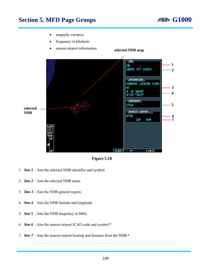
Section 5. MFD Page Groups G1000
• magnetic variance
• frequency in kilohertz
• nearest airport information selected NDB map
1 2
3 4
5 selected NDB
6 7
Figure 5.18
1. line 1 - lists the selected NDB identifier and symbol.
2. line 2 - lists the selected NDB name.
3. line 3 - lists the NDB general region.
4. line 4 - lists the NDB latitude and longitude.
5. line 5 - lists the NDB frequency in MHz.
6. line 6 - lists the nearest airport ICAO code and symbol.*
7. line 7 - lists the nearest airport bearing and distance from the NDB.*
109

Section 5. MFD Page Groups G1000
Instructions for using the NDB information page
1. click on the large FMS to go to the Waypoint Page Group. The text ‘WPT’ in the Page Group Window will be
highlighted.
2. use the small FMS knob to go to the NDB Information Page. The third rectangle in the Page Group Window
will be filled in blue.
3. click on the FMS knob to activate the blinking cursor. The blinking cursor will highlight the NDB ICAO field
in preparation for a new NDB selection. To change the display NDB, follow steps 3.1 – 3.3.
3.1 with the Intersection field highlighted, click on the large FMS knob to highlight the first NDB letter.
3.2 use the small FMS knob, or computer keyboard, to enter the desired NDB name.
3.4 click on the ENTER button to accept the selection. The NDB ICAO will be highlighted.
4. click on the large FMS knob to scroll the blinking cursor to the frequency field. Click on the ENTER key to
enter the selected NDB frequency directly into the ADF standby frequency field.
5. click on the FMS knob to stop and close the blinking cursor.
5.2.4 VOR Information Page
The VOR Information Page is the fourth page in the Waypoint Page Group (Figure 5.19). It is used to obtain
information on any VOR in the data base. Duplicate named VORs are listed in a popup window and the user can
select the appropriate one. The following information is displayed on the VOR Information Page:
• map of the surrounding area
• VOR identifier and symbol
• VOR name
• VOR closest city
• general location
110
• latitude/longitude
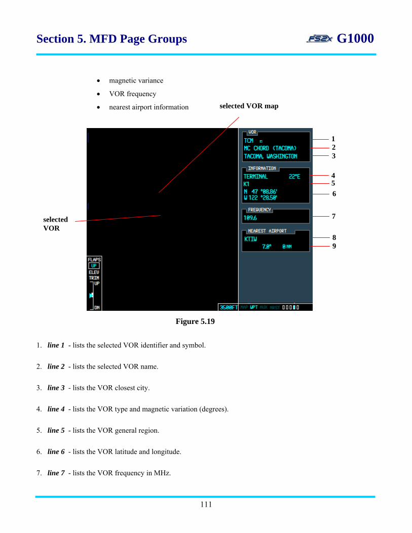
Section 5. MFD Page Groups G1000
• magnetic variance
• VOR frequency selected VOR map • nearest airport information
1. line 1 - lists the selected VOR identifier and symbol.
2. line 2 - lists the selected VOR name.
3. line 3 - lists the VOR closest city.
4. line 4 - lists the VOR type and magnetic variation (degrees).
5. line 5 - lists the VOR general region.
6. line 6 - lists the VOR latitude and longitude.
7. line 7 - lists the VOR frequency in MHz.
2 1
3
5 4
6
7selected VOR
89
Figure 5.19
111

Section 5. MFD Page Groups G1000
8. line 8 - lists the nearest airport ICAO code and symbol.*
9. line 9 - lists the nearest airport bearing and distance from the VOR.*
Instructions for using the VOR information page
1. click on the large FMS to go to the Waypoint Page Group. The text ‘WPT’ in the Page Group Window will be
highlighted.
2. use the small FMS knob to go to the VOR Information Page. The fourth rectangle in the Page Group Window
will be filled in blue.
3. click on the FMS knob to activate the blinking cursor. The blinking cursor will highlight the VOR ICAO field
in preparation for a new VOR selection. To change the display VOR, follow steps 3.1 – 3.3.
3.1 with the VOR field highlighted, click on the large FMS knob to highlight the first VOR letter.
3.2 use the small FMS knob, or computer keyboard, to enter the desired VOR ICAO code.
3.3 click on the ENTER button to accept the selection. The VOR ICAO will be highlighted.
4. click on the large FMS knob to scroll the blinking cursor to the frequency field. Click on the ENTER key to
enter the selected VOR frequency directly into the Nav1 standby frequency field.
4. click on the FMS knob to stop and close the blinking cursor.
5.2.5 USRWPT Information Page
The USRWPT Information Page is the fifth page in the Waypoint Page Group (Figure 5.20). It is used to define a
waypoint by reference to a specified geographical location. A user waypoint can be defined in 1 of 4 ways:
• aircraft location
112
• latitude and longitude position

Section 5. MFD Page Groups G1000
• bearing and distance from a specified location
• intersection of bearings from 2 specified locations
Regardless of the way the user waypoint location is defined, the specified location will always be listed as the
latitude and longitude displayed in the USRWPT Information Window. The user waypoints can be modified,
renamed, and deleted from this page. The following information is displayed on the USRWPT Information Page:
• map of the surrounding area
• identifier
• comment
• general location
• latitude/longitude
• reference waypoint with identifier, radial, and distance
• second reference waypoint with identifier and radial
• list of user waypoints selected USRWPT map
1
2
3 4
entered USRWPT
56
7
Figure 5.20
113

Section 5. MFD Page Groups G1000
1. line 1 - lists the user entered waypoint name. Maximum number of characters is 8.
2. line 2 - lists the user entered comment. Maximum number of characters is 8.
3. line 3 - lists the user waypoint general location.
4. line 4 - lists the user entered waypoint latitude and longitude.
5. line 5 - lists the first user entered reference waypoint identifier. Also lists the user entered bearing and
distance from the user waypoint.
6. line 6 - lists the second user entered reference waypoint identifier and bearing from the user waypoint.
7. line 7 - displays the list of user waypoints. Includes the waypoint name and the user comment corresponding
to the user waypoint.
Instructions for using the USRWPT information page
The user waypoint, regardless of how defined, will always display the user waypoint latitude/longitude position
when set. The default display lists the aircrafts current latitude/longitude position, and with no changes in other
variables becomes the user waypoint if the USRWPT is set. Alternatively, the user can scroll to the lat/lon field or
the reference fields, to enter a different user waypoint. Each time a new reference location is entered, it becomes
the new user waypoint and its latitude and longitude position is displayed in the USRWPT Information Window.
1. click on the large FMS to go to the Waypoint Page Group. The text ‘WPT’ in the Page Group Window will be
highlighted.
2. use the small FMS knob to go to the USRWPT Information Page. The fifth rectangle in the Page Group
Window will be filled in blue.
3. click on the FMS knob to activate the blinking cursor. The blinking cursor will highlight the first letter position
in the USRWPT Name field in preparation for an entry. To change the display USRWPT Name, follow steps
3.1 – 3.4.
114

Section 5. MFD Page Groups G1000
3.1 use the small FMS knob to enter a user waypoint name. Characters go from A-Z, followed by
numbers 0-9, and then by symbols, and back again to the letters. Scroll forward using the small
large FMS knob click spot and scroll backwards using the left small FMS knob.
3.2 use the large FMS knob to shift the blinking cursor between letter fields.
3.3 click on the ENTER button to display a popup window where you can choose, or not, to create the
USRWPT entered (Figure 5.21). Use the small FMS knob to toggle between the choices.
Figure 5.21
3.4 click on the ENTER button to accept your choice; the window will close and the Comment field will
be highlighted. The entered name will be displayed in the user waypoint box at the bottom.
4. to change the contents of the Comment field, follow steps 4.1 – 4.3:
4.1 use the small FMS knob to enter a comment. Characters go from A-Z, followed by numbers 0-9, and
then by symbols, and back again to the letters. Scroll forward using the right small FMS knob click
spot and scroll backwards using the left small FMS knob.
4.2 use the large FMS knob to shift the blinking cursor between letter fields.
4.3 click on the ENTER button to accept the entered comment. This will also shift the blinking cursor to
the first number in the Latitude field.
5. use the large FMS knob to scroll through the Latitude and Longitude fields without entering a value if you are
not defining the reference waypoint by lat/lon location. To change the latitude and longitude values, follow
steps 5.1 – 5. 3:
115

Section 5. MFD Page Groups G1000
5.1 use the large FMS knob to scroll through the blinking cursor through the latitude and longitude
number fields.
5.2 use the small FMS knob to change the value in the highlighted number field.
5.3 click on the ENTER button to accept your choice; the blinking cursor will shift to the First Reference
Waypoint ICAO field.
6. with the First Reference Waypoint ICAO field highlighted, click on the small FMS knob to highlight the first
letter of the ICAO code.
6.1 use the small FMS knob, or computer keyboard, to enter the First Reference Waypoint ICAO.
6.2 click on the ENTER button to accept the selection. The blinking cursor will shift to highlight the
whole number part of the first reference waypoint Bearing Field.
7. to change the first reference waypoint bearing, follow steps 7.1 – 7.3:
7.1 with the whole number of the first reference waypoint bearing highlighted, click on the right small
FMS knob to increase the value, and click on the left small FMS knob to decrease the value.
7.2 use the right large FMS knob to shift the blinking cursor to the fractional number part of the bearing
field.
7.3 use the small FMS knob to change the fractional bearing value. Click on the right small FMS knob to
increase the value, and click on the left small FMS knob to decrease the value.
8. use the right large FMS knob to shift the blinking cursor to the whole number part of the First Reference
Waypoint Distance field. To change the first reference waypoint distance, follow steps 8.1 – 8.3:
8.1 with the whole number of the first reference waypoint distance highlighted, click on the right small
FMS knob to increase the value, and click on the left small FMS knob to decrease the value.
8.2 use the right large FMS knob to shift the blinking cursor to the fractional number part of the distance
field.
116
Section 5. MFD Page Groups G1000
8.3 use the small FMS knob to change the fractional distance value. Click on the right small FMS knob
to increase the value, and click on the left small FMS knob to decrease the value.
9. use the right large FMS knob to shift the blinking cursor to the Second Reference Waypoint ICAO field. To
change the Second Reference Waypoint ICAO code, follow steps 9.1 – 9.3:
9.1 with the Second Reference Waypoint ICAO field highlighted, click on the small FMS knob to
highlight the first letter of the Second Reference Waypoint ICAO code.
9.2 use the small FMS knob, or computer keyboard, to enter the desired Second Reference Waypoint
ICAO code. Use the large FMS knob to shift the blinking cursor between letter fields.
9.3 click on the ENTER button to accept the selection. The Second Reference Waypoint ICAO field will
be highlighted.
10. use the large FMS knob to highlight the Second Reference Waypoint Bearing field. To change the second
reference waypoint bearing, follow steps 10.1 – 10.3:
10.1 with the whole number of the second reference waypoint bearing field highlighted, click on the right
small FMS knob to increase the value, and click on the left small FMS knob to decrease the value.
10.2 use the right large FMS knob to shift the blinking cursor to the fractional number part of the bearing
field.
10.3 use the small FMS knob to change the fractional bearing value. Click on the right small FMS knob
to increase the value, and click on the left small FMS knob to decrease the value.
11. click on the FMS knob to stop and close the blinking cursor.
117

Section 5. MFD Page Groups G1000
5.3 MFD Auxiliary Page Group
The MFD Auxiliary Page Group is the third group of the MFD Main Page Groups and is divided into 5 different
page groups (see Table 1). The information available on these pages is very detailed and includes the following:
• trip status and planning
• fuel status and planning
• physical properties information (wind, density altitude, TAS, etc.)
• satellite status
• RAIM prediction
• system settings
• LRU status
• database information
5.3.1 AUX Trip Planning Page
The Trip Planning Page is the first page of the AUX Page Group and provides information that can be used for
trip planning (Figure 5.22). This information is divided into an upper display and a lower display. The upper
display lists information that can be changed by the user. The lower display lists data that cannot be changed by
the user, but change according to the values set in the upper display.
Enter a departure waypoint and a destination waypoint, a departure time, desired ground speed, desired fuel flow
and fuel-on-board, and the G1000 will calculate and display the corresponding flight data in the lower panel
fields. The information in the lower display is divided into 3 different stats groups:
• trip stats
• fuel stats
• other stats
There are 2 planning modes available; AUTOMATIC and MANUAL. In the AUTOMATIC mode, all
information displayed in the lower panels is automatically computed and displayed from system sensors. In the
MANUAL mode, the G1000 can display information based on specific user inputted parameters. There are 3
different trip modes available for planning, all of which can be used in the AUTO or MAN mode:
118
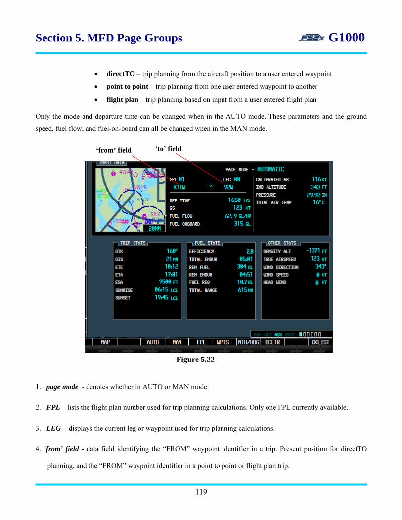
Section 5. MFD Page Groups G1000
• directTO – trip planning from the aircraft position to a user entered waypoint
• point to point – trip planning from one user entered waypoint to another
• flight plan – trip planning based on input from a user entered flight plan
Only the mode and departure time can be changed when in the AUTO mode. These parameters and the ground
speed, fuel flow, and fuel-on-board can all be changed when in the MAN mode.
1. page mode - denotes whether in AUTO or MAN mode.
2. FPL – lists the flight plan number used for trip planning calculations. Only one FPL currently available.
3. LEG - displays the current leg or waypoint used for trip planning calculations.
4. ‘from’ field - data field identifying the “FROM” waypoint identifier in a trip. Present position for directTO
planning, and the “FROM” waypoint identifier in a point to point or flight plan trip.
Figure 5.22
‘to’ field ‘from’ field
119
Section 5. MFD Page Groups G1000
5. ‘to’ field - data field identifying the “TO” waypoint identifier in a trip. Displayed as the “TO” waypoint
identifier for all 3 trip types.
6. dep time - lists the local time in an hrs:min format in the AUTO mode. Value can be changed in the MAN
mode.
7. gs - displays the current ground speed, in knots, in the auto mode. Value can be changed in the MAN mode.
8. fuel flow - displays the current fuel flow, in gallons/hour, in the auto mode. Value can be changed in the MAN
mode.
9. fuel on board - displays the current gallons of fuel on board in the auto mode. Value can be changed in the
MAN mode.
10. calibrated airspeed - displays the calibrated airspeed in knots. Value can be changed in the MAN mode.
11. ind altitude - displays the current gallons of fuel on board in the auto mode. Value can be changed in the
MAN mode.
12. pressure - displays the current barometric pressure (inches of mercury) in the auto mode. Value can be
changed in the MAN mode.
13. total air temp - displays the current total air temperature in degrees Celsius in the auto mode. Value can be
changed in the MAN mode.
TRIP STATS
14. dtk - displays the required direction, degrees magnetic North, to the next waypoint.
15. dis - displays the distance in nm or km to the next waypoint.
16. ETE - displays the estimated time enroute to the next waypoint in an hrs:min format if the ETE is greater than
1 hour, and in a min:sec format if it is less than 1 hour.
17. ETE - displays the estimated time of arrival at the next waypoint in an hrs:min format.
120

Section 5. MFD Page Groups G1000
18. ESA - displays the estimated safe altitude enroute to the next waypoint in feet or meters ASL. *
19. sunrise - displays the destination sunrise time in hrs:min format. No functional significance in the fs2x
G1000.
20. sunset - displays the destination sunset time in hrs:min format. No functional significance in the fs2x G1000.
FUEL STATS 21. efficiency - displays the efficiency as nautical miles per gallon.
22. total endurance – displays the remaining flight time in an hrs:min format based on the fuel onboard and a
continuation of the current flight conditions.
23. rem fuel - displays the remaining fuel onboard upon reaching the selected leg.
24. rem endur - displays the fuel endurance remaining at the end of the selected leg.
25. fuel req - displays the fuel in gallons required for the trip.
26. total range - displays the flight distance in nm based on the current fuel flow.
OTHER STATS
26. density altitude - displays the density altitude in feet or meters ASL.
27. true airspeed - displays the true airspeed in knots.
28. wind direction - displays the wind direction as degrees magnetic North.
29. wind speed - displays the wind speed in knots.
28. head/tail wind - displays the wind speed component, in knots, corresponding to a head wind or a tail wind.
‘HEAD WIND’ is displayed if a head wind, and ‘TAIL WIND’ displayed if a tail wind. Only displayed in the
AUTO mode.
121

Section 5. MFD Page Groups G1000
Instructions for using the Auxiliary Trip Planning page
There are initially 3 options available when this page is opened; 1) display information based on user defined
waypoints, 2) display information based on a pre-determined flight plan, or 3) display information based on user
entered physical data (fuel, altitude, ground speed, etc.). These options are accessible via softkeys available only
on this page.
1. click on the large FMS to go to the Auxiliary Page Group. The text ‘AUX’ in the Page Group Window will be
highlighted and the first rectangle will be filled in blue.
2. to display information based on user defined waypoints, click on the WPTS softkey. The ‘from’ field will be
highlighted and the letters P.POS will be displayed. At this time, the user can choose between the DirectTo
mode and Point To Point mode. For DirectTo planning follow steps 2.1 – 2.6, and for Point To Point planning
follow steps 2.7 – 2.11.
2.1 with the ‘from’ field highlighted click on the ENTER button. This shifts the blinking cursor to the
‘to’ field.
2.2 click on the small FMS knob to highlight the first letter of the ICAO code.
2.3 use the large and small FMS knobs, or the keyboard, to enter the desired code, and then click on the
ENTER button. The ‘to’ field will again be highlighted.
2.4 use the large FMS to scroll to the departure time field.
2.5 enter the departure time using the large and small FMS knobs. Alternatively, use the large FMS knob
to scroll backwards to the ‘from’ field where entering an ICAO code activates the Point To Point
mode.
2.6 this is all the data that can be changed in the DTO AUTO mode. To change other data, go to the
MAN mode.
2.7 with the ‘from’ field highlighted click on the small FMS knob to highlight the first letter of the
ICAO code.
122
Section 5. MFD Page Groups G1000
2.8 use the large and small FMS knobs, or the keyboard, to enter the desired code, and then click on the
ENTER button. The ‘from’ field will again be highlighted.
2.9 use the large FMS to highlight the departure time field.
2.10 enter the departure time using the large and small FMS knobs. Alternatively, use the large FMS
knob to scroll backwards to the ‘from’ field to re-enter an ICAO code.
2.11 this is all the data that can be changed in the point-to-point AUTO mode. To change other data, go
to the MAN mode.
3. to display information based on a user entered flight plan, click on the FPL softkey. The FPL field will be
highlighted.
3.1 use the small FMS knob to change to the desired flight plan. (Note: only 1 flight plan is currently
available in the fs2x G1000. This emulation is to suffice until multiple flight plans are available.)
3.2 click on the large FMS knob to shift to the LEG field.
3.3 use the small FMS knob to scroll through the different legs of the flight plan. The current leg number is
displayed in the LEG field. Trip stats will change as they are specific for each leg. Following the last leg,
the LEG field will display the term CUM indicating the trip stats displayed refer to the entire flight plan
trip, and not to individual legs.
3.4. use the large FMS to highlight the departure time field.
3.5 enter the departure time using the large and small FMS knobs. Alternatively, use the large FMS knob to
scroll backwards to the ‘from’ field where entering an ICAO code activates the Point To Point mode.
3.6 this is all the data that can be changed in the FPL AUTO mode. To change other data, go to the MAN
mode.
4. to display information based on user entered physical data, click on the MAN softkey in any trip mode.
4.1 use the large and small FMS knobs to enter the mode (DTO, PT to PT, FPL) and departure time as
discussed above for the AUTO mode.
123

Section 5. MFD Page Groups G1000
4.2 click on the large FMS knob to scroll the cursor to one of the other changeable parameters (GS, FF,
FOB).
4.3 use the small FMS knob to change the highlighted parameter.
5. click on the FMS knob at any time to close the blinking cursor and re-gain the option of using the FMS knobs
to change pages and page groups.
5.3.2 AUX Utility Page
The Utility Page is the second page of the AUX Page Group (Figure 5.23), and provides the following
information and functions:
• generic timer
• flight timer
• departure timer
• odometer
• trip odometer
• average ground speed
• maximum groundspeed
• scheduler
This information is divided into 3 groups; 1) TIMERS, 2) TRIP STATISTICS, AND 3) SCHEDULER. The
generic timer is started, stopped and reset from the default Utility Page display, the other timers and the trip
statistics are reset using the Utility Page Menu Window (Figure 5.23). The event scheduling section has no
functional significance in the fs2x G1000.
124
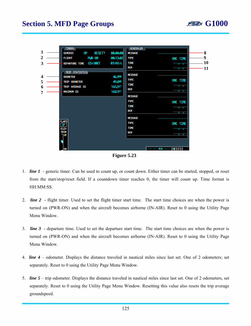
Section 5. MFD Page Groups G1000
1
3 2
8
11
9 10
5 4
7 6
Figure 5.23
1. line 1 - generic timer. Can be used to count up, or count down. Either timer can be started, stopped, or reset
from the start/stop/reset field. If a countdown timer reaches 0, the timer will count up. Time format is
HH:MM:SS.
2. line 2 - flight timer. Used to set the flight timer start time. The start time choices are when the power is
turned on (PWR-ON) and when the aircraft becomes airborne (IN-AIR). Reset to 0 using the Utility Page
Menu Window.
3. line 3 - departure time. Used to set the departure start time. The start time choices are when the power is
turned on (PWR-ON) and when the aircraft becomes airborne (IN-AIR). Reset to 0 using the Utility Page
Menu Window.
4. line 4 – odometer. Displays the distance traveled in nautical miles since last set. One of 2 odometers; set
separately. Reset to 0 using the Utility Page Menu Window.
5. line 5 – trip odometer. Displays the distance traveled in nautical miles since last set. One of 2 odometers, set
separately. Reset to 0 using the Utility Page Menu Window. Resetting this value also resets the trip average
groundspeed.
125

Section 5. MFD Page Groups G1000 6. line 6 – trip average GS. Displays the average groundspeed in knots since last set. Reset to 0 using the Utility
Page Menu Window. Automatically reset to 0 when the trip odometer is reset to 0.
7. line 7 – maximum GS. Displays the maximum groundspeed in knots since last set. Reset to 0 using the Utility
Page Menu Window.
8. line 8 – message field. Used to name the scheduled event.*
9. line 9 – type field. Used to enter the message alert type. Choices include:*
• one-time - alert when the message timer reaches 0 (default)
• event - alert at the specified date and time
• periodic - alert each time the message timer reaches 0
10. line 10 – time field. Used to set the amount of time to the event. Time format is HH:MM:SS.*
11. line 11 – rem field. Displays the time remaining to the scheduled event. Time format is HH:MM:SS.*
12 13
15 14
17 16
Figure 5.24
12. line 12 - resets the flight timer to 0. Timer restarts from that time.
13. line 13 - resets the departure time to the current local time.
14. line 14 - resets the trip odometer and average groundspeed to 0. Values are re-determined from this point.
15. line 15 - resets the odometer to 0. Values are re-determined from this point.
126

Section 5. MFD Page Groups G1000 16. line 16 - resets the maximum speed value. Values are re-determined from this point.
17. line 17 - resets all values trip statistics values to 0. Values are re-determined from this point.
Instructions for using the Auxiliary Utility page
1. click on the large FMS to go to the Auxiliary Page Group. The text ‘AUX’ in the Page Group Window will be
highlighted and the first rectangle will be filled in blue.
2. click on the small FMS to go to the Auxiliary Utility Page. The second rectangle will be filled in blue.
3. click on the FMS knob to activate the flashing cursor.
4. to set the generic timer to up or down: Use the large FMS knob to scroll the flashing cursor to the UP/DN
field. Click on the left small FMS knob to set the DN timer, and the right small FMS knob to set the UP timer.
5. to start, stop, or reset the generic timer: Use the large FMS knob to scroll the flashing cursor to the
Start/Stop/Reset field field. Click on the left small FMS knob to scroll backwards through the choices, and the
right small FMS knob to scroll forwards. Click on the ENTER key to activate the function.
6. to name a scheduled event: Use the large FMS knob to scroll to the MESSAGE field. Use the small FMS
knob to change the letters, and the large FMS knob to change between letters. Maximum name length is 10.
7. to set the message alert type: Use the large FMS knob to scroll to the TYPE field. Use the small FMS knob to
change the letters, and the large FMS knob to change between letters.
8. to set the schedule time: Use the large FMS knob to scroll to the TIME field. Use the small FMS knob to
change the numbers, and the large FMS knob to change between numbers.
9. click on the FMS knob at any time to close the blinking cursor and re-gain the option of using the FMS knobs
to change pages and page groups.
10. to reset the flight timer time, departure time, odometer readouts, or groundspeed data, click on the MENU
button to display the Utility Page Menu Window (Figure 5.25).
127
10.1 use the small FMS knob to scroll between the different available data fields and highlight the
desired function.
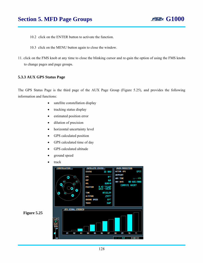
Section 5. MFD Page Groups G1000
10.2 click on the ENTER button to activate the function.
10.3 click on the MENU button again to close the window.
11. click on the FMS knob at any time to close the blinking cursor and re-gain the option of using the FMS knobs
to change pages and page groups.
5.3.3 AUX GPS Status Page
The GPS Status Page is the third page of the AUX Page Group (Figure 5.25), and provides the following
information and functions:
• satellite constellation display
• tracking status display
• estimated position error
• dilution of precision
• horizontal uncertainty level
• GPS calculated position
• GPS calculated time of day
• GPS calculated altitude
• ground speed
• track
Figure 5.25
128
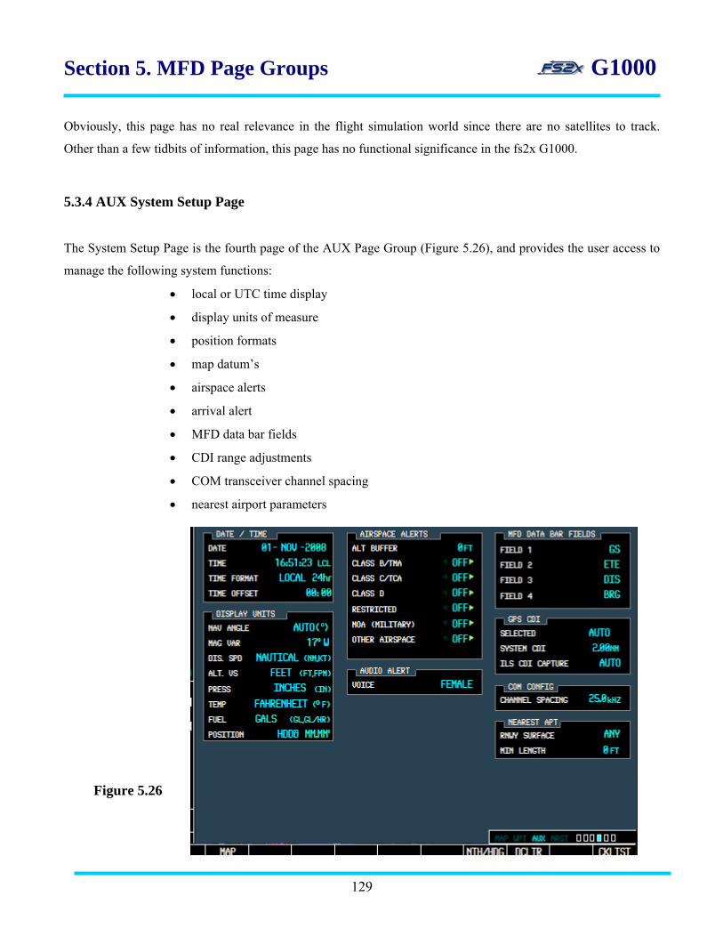
Section 5. MFD Page Groups G1000
Obviously, this page has no real relevance in the flight simulation world since there are no satellites to track.
Other than a few tidbits of information, this page has no functional significance in the fs2x G1000.
5.3.4 AUX System Setup Page
The System Setup Page is the fourth page of the AUX Page Group (Figure 5.26), and provides the user access to
manage the following system functions:
• local or UTC time display
• display units of measure
• position formats
• map datum’s
• airspace alerts
• arrival alert
• MFD data bar fields
• CDI range adjustments
• COM transceiver channel spacing
• nearest airport parameters
Figure 5.26
129
Section 5. MFD Page Groups G1000
1. date/time box - displays the current date and time, and allows the user to change the displayed time format
and time offset.
1.1 date field – lists the current date in DD-Month-YY format.
1.2 time field – lists the current time.
1.3 time format field – used to set the time format. Available formats are listed below. Local 24 hrs is the
default format.
• local 24 hrs
• local 12 hrs
• UTC
1.4. time offset – used to define current local time. Subtract or add the offset when using a local time
format as required.
2. display units box - used to change units of measure.
2.1 nav angle – used to change units of angle measurements. There are 2 choices (AUTO is the default
setting):
• AUTO – navigation angles are set to magnetic North. Magnetic variance is figured into
displayed values.
• TRUE - navigation angles are set to true North and the letter ‘T’ is displayed next to the
value. Magnetic variance is not accounted for in the displayed values.
2.1.1 the nav angle settings affect the following displays:
• BRG display in the PFD Navigation Status Bar
• current heading, selected heading, and selected course box on the PFD
• BRG, DTK, TKE, TRK, AND XTK fields in the MFD Navigation Status Box
3.2 mag var field – displays degrees magnetic variance.
130

Section 5. MFD Page Groups G1000
3.3 dis. spd – used to change between nautical and metric units in distance and speed displays. Default
setting is nautical.
3.3.1 the dis. spd settings affect the following displays:
• DIS display in the PFD Navigation Status Bar
• all distance and speed displays on the MFD, except the wind speed displayed on the
Navigation Map Page
• wind speed on the Trip Planning Page
3.4 alt. vs – used to change between feet and meters units in altitude and vertical speed displays. Default
setting is feet.
3.4.1 the alt. vs settings affect the following displays:
• all elevation and altitude displays on the MFD
3.5 press - used to change between inches of mercury and hectopascals units in altitude and pressure
displays. Default setting is inches of mercury.
3.5.1 the press settings affect the following displays:
• altimeter settings on the PFD
• pressure display on the Trip Planning Page
3.6 temp - used to change between Fahrenheit and Celsius units in temperature displays. Default setting
is Fahrenheit.
3.6.1 the temp settings affect the following displays:
• all temperature displays on the PFD
• temperature display on the Trip Planning Page
3.7 fuel - used to change between pounds and kilograms units in fuel displays. Default setting is pounds
131
3.7.1 the fuel settings affect the following displays:
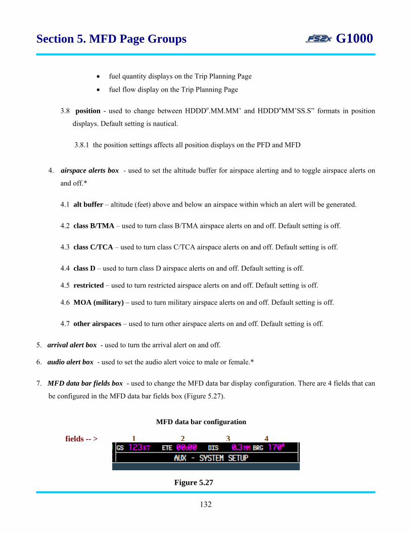
Section 5. MFD Page Groups G1000
• fuel quantity displays on the Trip Planning Page
• fuel flow display on the Trip Planning Page
3.8 position - used to change between HDDDo.MM.MM’ and HDDDoMM’SS.S” formats in position
displays. Default setting is nautical.
3.8.1 the position settings affects all position displays on the PFD and MFD
4. airspace alerts box - used to set the altitude buffer for airspace alerting and to toggle airspace alerts on
and off.*
4.1 alt buffer – altitude (feet) above and below an airspace within which an alert will be generated.
4.2 class B/TMA – used to turn class B/TMA airspace alerts on and off. Default setting is off.
4.3 class C/TCA – used to turn class C/TCA airspace alerts on and off. Default setting is off.
4.4 class D – used to turn class D airspace alerts on and off. Default setting is off.
4.5 restricted – used to turn restricted airspace alerts on and off. Default setting is off.
4.6 MOA (military) – used to turn military airspace alerts on and off. Default setting is off.
4.7 other airspaces – used to turn other airspace alerts on and off. Default setting is off.
5. arrival alert box - used to turn the arrival alert on and off. 6. audio alert box - used to set the audio alert voice to male or female.*
7. MFD data bar fields box - used to change the MFD data bar display configuration. There are 4 fields that can
be configured in the MFD data bar fields box (Figure 5.27).
MFD data bar configuration
1 2 3 4fields -- >
Figure 5.27
132

Section 5. MFD Page Groups G1000
7.1 all 4 MFD Data Bar fields are capable of displaying the same information. The available choices are
listed below:
• GS – groundspeed
• ETE – estimated time enroute
• DIS – distance
• BRG – bearing
• ETA – estimated time of arrival
• DTK – direct
• TRK – tracking
• TKE – tracking angle error
• XTK- crosstrack error
• VSR – vertical speed required
• ESA – estimated safe altitude
• MSA – minimum safe altitude
• TAS – true airspeed
7.2 the default configuration is shown in Figure 5.28.
7.3 the identities of the 4 data fields are listed in Figure 5.28 above each field in bold brown numbering.
8. GPS/CDI box – used to define the range of the course deviation indicator (CDI). Range values are the full
range deflection of the CDI to either side of center. Also displays the current system CDI value, and allows
the user to choose between an automatic and manual ILS CDI capture modes.
In the default setup, the CDI range is set to 1 nautical mile when leaving the departure airport, and then goes
up to 2 nm at 30 nautical miles and remains at 2 nautical miles during the enroute phase of flight. The CDI
range goes down to 1 nautical mile when the arrival airport is within 31 nautical miles (terminal area). The
CDI range further goes to 0.3 nautical miles during approach operations when within 2 nautical miles of the
final approach fix.
If a CDI range entered by the user is smaller than the system CDI range, the user entered CDI range value is
used from that point on until entering a phase with a lower system CDI range.
133

Section 5. MFD Page Groups G1000
8.1 selected – used to set the CDI range. There are 4 choices:
• auto (default)
• 2 nautical miles
• 1 nautical miles
• 0.3 nautical miles
8.2 system CDI - displays the current system CDI setting. The value cannot be changed directly by the
user.
8.3 ILS CDI capture - used to toggle between the automatic (AUTO) and manual (MAN) ILS CDI
capture modes.
9. COM config box – used to select between 8.33 kHz and 25 kHz COM frequency channel spacing.
10. nearest apt box – used to set the minimum runway length and surface type an airport must have for its
inclusion on the MFD Nearest Airport Page.
10.1 rnwy surface – used to select airports for the nearest airport page based on runway surface type.
Allows the user to prevent airports from being displayed that do not have a runway of sufficient
length or surface type to be usable. Choices include the following:
• any (default) – airports with any runway surface type included.
• hard only – only airports with a hard runway surface included.
• hard/soft – airports with a hard or soft runway surface included.
• water – only airports with water landings included.
10.2 min length – used to enter the minimum runway length (feet) required for inclusion into the nearest
airport list. Runway length value ranges from 0 to 20,000 feet, and is changed in units of 1000
feet.
Instructions for using the System Setup page
134

Section 5. MFD Page Groups G1000
1. click on the large FMS to go to the Auxiliary Page Group. The text ‘AUX’ in the Page Group Window will be
highlighted and the first rectangle will be filled in blue.
2. click on the small FMS to go to the Auxiliary System Setup Page. The fourth rectangle will be filled in blue.
3. click on the FMS knob to activate the flashing cursor.
4. use the large FMS knob to scroll the blinking cursor forward and backward through the changeable data fields.
Use the small FMS knob to toggle between choices within a changeable data field.
5. click on the FMS knob at any time to close the blinking cursor and re-gain the option of using the FMS knobs
to change pages and page groups.
5.3.5 AUX Satellite Page
The XM Satellite Page is the fifth page in the Auxiliary Page Group, and provides information about satellite
radio and weather programs when they are installed. This page has no functional significance in the fs2xG100. It
is displayed to emulate the real world page, and to reserve the space for later use.
5.3.6 AUX System Status Page The System Status Page is the sixth and final page in the Auxiliary Page Group, and lists the status and software
version numbers for all system LRUs. Airframe and database information is also displayed. This page has no
functional significance in the fs2xG100. It is displayed to emulate the real world page, and to reserve the space for
later use.
5.4 MFD Nearest Page Group
The Nearest Page Group is the fourth page group of the MFD Page Groups, and displays information on the
nearest airports, navaids (intersections, NDBs, VORs), user waypoints, frequencies, and airspaces. The Nearest
Page Group is sub-divided into 7 unique pages (see Table 1). Any airport, intersection, NDB, or VOR on their
respective nearest pages can be designated as the DTO waypoint by clicking on the DTO button when the facility
is highlighted.
135
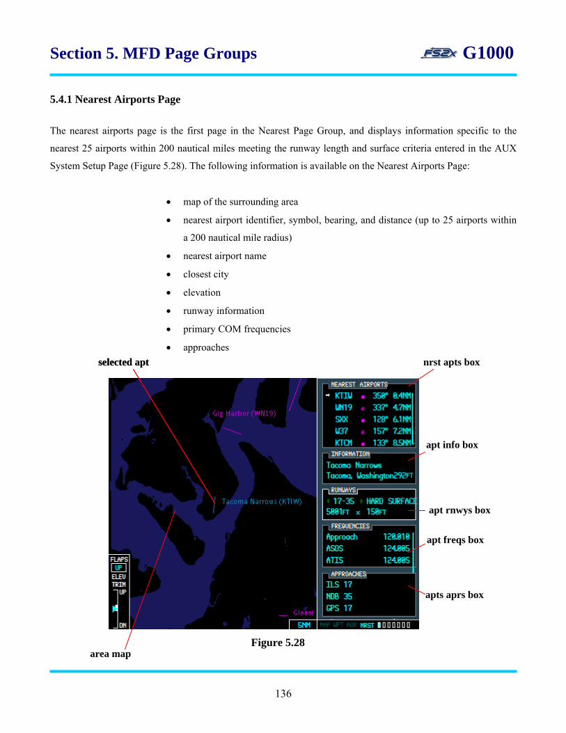
Section 5. MFD Page Groups G1000
5.4.1 Nearest Airports Page
The nearest airports page is the first page in the Nearest Page Group, and displays information specific to the
nearest 25 airports within 200 nautical miles meeting the runway length and surface criteria entered in the AUX
System Setup Page (Figure 5.28). The following information is available on the Nearest Airports Page:
• map of the surrounding area
• nearest airport identifier, symbol, bearing, and distance (up to 25 airports within
a 200 nautical mile radius)
• nearest airport name
• closest city
• elevation
• runway information
• primary COM frequencies
• approaches
Figure 5.28
nrst apts box selected apt selected apt
apt info box
apt rnwys box
apt freqs box
apts aprs box
area map
136

Section 5. MFD Page Groups G1000
1. nrst apts box - displays 5 of the 25 nearest airports available. Airports are listed in order of their “nearness”
starting with the uppermost listed airport as the nearest. The nearest airport list is scrollable to allow the user
to view all 25 nearest airports available. The selected airport is identified by a blinking cursor and a right
pointing arrow and arrowhead. The following information is displayed for each airport:
• ICAO identifier code
• airport type symbol
• airport bearing
• airport distance
2. apt info box - the airport information box displays the following information about the selected airport:
• airport name
• airport closest city
• airport elevation
3. apt rnwys box - the airport runways box displays the following information about the selected airport
runways:
• runways available
• runway direction
• runway surface type
• runway length and width
4. apt freqs box - the airport frequencies box displays the primary communications frequencies and type.
5. apt aprs box - the airport approaches box displays the available approaches for the selected airport.
Instructions for using the Nearest Airports page
1. click on the large FMS to go to the Nearest Page Group. The text ‘NRST’ in the Page Group Window will be
highlighted and the first rectangle will be filled in blue.
137
2. there will be 4 relevant softkeys displayed on the softkey panel corresponding to the 4 changeable data boxes
in the nearest airports window (Figure 5.29).
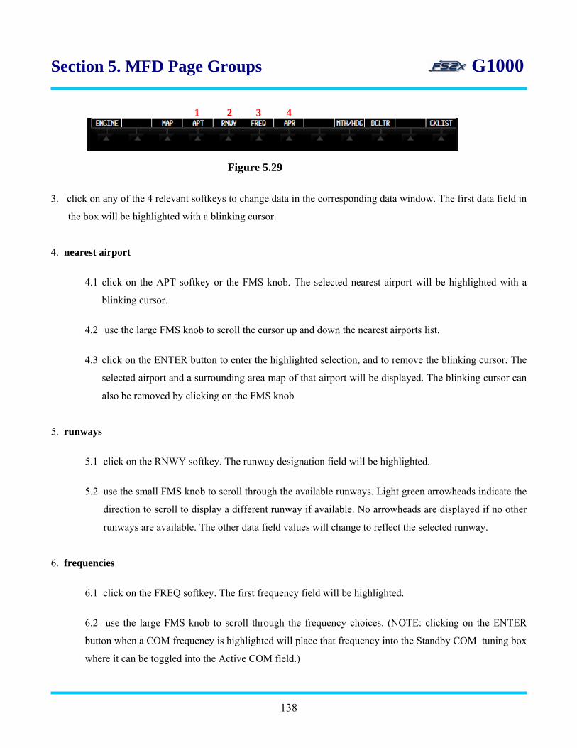
Section 5. MFD Page Groups G1000
1 2 3 4
Figure 5.29
3. click on any of the 4 relevant softkeys to change data in the corresponding data window. The first data field in
the box will be highlighted with a blinking cursor.
4. nearest airport
4.1 click on the APT softkey or the FMS knob. The selected nearest airport will be highlighted with a
blinking cursor.
4.2 use the large FMS knob to scroll the cursor up and down the nearest airports list.
4.3 click on the ENTER button to enter the highlighted selection, and to remove the blinking cursor. The
selected airport and a surrounding area map of that airport will be displayed. The blinking cursor can
also be removed by clicking on the FMS knob
5. runways
5.1 click on the RNWY softkey. The runway designation field will be highlighted.
5.2 use the small FMS knob to scroll through the available runways. Light green arrowheads indicate the
direction to scroll to display a different runway if available. No arrowheads are displayed if no other
runways are available. The other data field values will change to reflect the selected runway.
6. frequencies
6.1 click on the FREQ softkey. The first frequency field will be highlighted.
6.2 use the large FMS knob to scroll through the frequency choices. (NOTE: clicking on the ENTER
button when a COM frequency is highlighted will place that frequency into the Standby COM tuning box
where it can be toggled into the Active COM field.)
138

Section 5. MFD Page Groups G1000 7. approaches
7.1 click on the APR softkey. The first approach field will be highlighted.
7.2 use the large FMS knob to scroll through a list of the available approaches.
5.4.2 Nearest Intersections Page
The nearest intersections page is the second page in the Nearest Page Group, and displays information specific to
the nearest 25 intersections within 200 nautical miles (Figure 5.30). The following information is available on the
Nearest Intersections Page:
• map of the surrounding area (range adjustable)
• nearest intersection identifier, symbol, bearing, and distance (up to a 200 nautical
mile radius)
• intersection latitude and longitude coordinates
• reference VOR name
• reference VOR symbol
• reference VOR frequency
• reference VOR bearing
• referenceVOR distance
selected int
int ref VOR box
nrst ints box
int info box Figure 5.30
area map
139
Section 5. MFD Page Groups G1000 1. nrst ints box - displays 11 of the 25 nearest intersections at one time. Intersections are listed in order of their
“nearness” starting with the uppermost listed intersection as the nearest. The nearest intersection list is
scrollable to allow the user to view all 25 nearest intersections available. The selected intersection is identified
by a blinking cursor and a right pointing arrow and arrowhead. The following information is displayed for
each intersection:
• ICAO identifier code
• intersection symbol
• intersection bearing
• intersection distance
2. int info box - the intersection information box displays the latitude and longitude (degrees: minutes) of the
selected intersection.
3. int ref VOR box - the intersection reference VOR box displays the following information about the selected
intersection reference VOR:
• name of reference VOR
• reference VOR symbol
• reference VOR frequency
• bearing to reference VOR
• distance to reference VOR
Instructions for using the Nearest Intersections page
1. click on the large FMS to go to the Nearest Page Group. The text ‘NRST’ in the Page Group Window will be
highlighted and the first rectangle will be filled in blue.
2. click on the small FMS to go to the Nearest Intersections page. The second rectangle will be filled in blue.
3. click on the FMS knob. The selected nearest intersection will be highlighted with a blinking cursor.
4. use the large FMS knob to scroll the cursor up and down the nearest intersections list.
140

Section 5. MFD Page Groups G1000
5. click on the ENTER button to enter the highlighted selection, and to remove the blinking cursor. The selected
intersection and a surrounding area map of that intersection will be displayed. The blinking cursor can also be
removed by clicking on the FMS knob.
5.4.3 Nearest NDBs Page
The nearest NDBs page is the third page in the Nearest Page Group, and displays information specific to the
nearest 25 NDBs within 200 nautical miles (Figure 5.31). The following information is available on the Nearest
NDBs Page:
• map of the surrounding area (range adjustable)
• nearest NDB identifier, symbol, bearing, and distance (up to a 200 nm radius)
• nearest NDB information
• nearest NDB frequency
nrst NDBs box selected NDB
Figure 5.31 area map
NDB info box
NDB freq box
141

Section 5. MFD Page Groups G1000 1. nrst NDBs box - displays 11 of the 25 nearest NDBs at one time. Intersections are listed in order of their
“nearness” starting with the uppermost listed NDB as the nearest. The nearest NDBs list is scrollable to allow
the user to view all 25 nearest NDBs available. The selected NDB is identified by a blinking cursor and a
right pointing arrow and arrowhead. The following information is displayed for each NDB:
• NDB identifier
• NDB symbol
• NDB bearing
• NDB distance
2. NDB info box - the NDB information box displays the following information about the selected NDB:
Line 1 - NDB name
Line 2 - NDB location (closest city)
Line 3 -NDB latitude
Line 4 -NDB longitude
3. NDB freq box - the NDB frequency box displays the selected NDB frequency.
Instructions for using the Nearest NDBs page
1. click on the large FMS to go to the Nearest Page Group. The text ‘NRST’ in the Page Group Window will be
highlighted and the first rectangle will be filled in blue.
2. click on the small FMS to go to the Nearest NDBs page. The third rectangle will be filled in blue.
3. click on the FMS knob. The selected nearest NDB will be highlighted with a blinking cursor.
4. use the large FMS knob to scroll the cursor up and down the nearest NDBs list. 5. click on the ENTER button to enter the highlighted selection, and to remove the blinking cursor. The selected
NDB and a surrounding area map of that NDB will be displayed. The blinking cursor can also be removed by
clicking on the FMS knob.
142
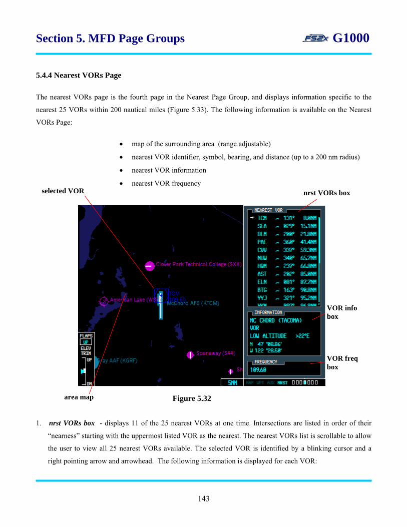
Section 5. MFD Page Groups G1000 5.4.4 Nearest VORs Page
The nearest VORs page is the fourth page in the Nearest Page Group, and displays information specific to the
nearest 25 VORs within 200 nautical miles (Figure 5.33). The following information is available on the Nearest
VORs Page:
• map of the surrounding area (range adjustable)
• nearest VOR identifier, symbol, bearing, and distance (up to a 200 nm radius)
• nearest VOR information
• nearest VOR frequency selected VOR nrst VORs box
1. nrst VORs box - displays 11 of the 25 nearest VORs at one time. Intersections are listed in order of their
“nearness” starting with the uppermost listed VOR as the nearest. The nearest VORs list is scrollable to allow
the user to view all 25 nearest VORs available. The selected VOR is identified by a blinking cursor and a
right pointing arrow and arrowhead. The following information is displayed for each VOR:
Figure 5.32 area map
VOR info box
VOR freq box
143
Section 5. MFD Page Groups G1000
• VOR identifier
• VOR symbol
• VOR bearing
• VOR distance
2. VOR info box - the NDB information box displays the following information about the selected VOR:
Line 1 - VOR name
Line 2 - VOR location (closest city)
Line 3 - VOR type and magnetic variation
Line 4 - VOR latitude
Line 5 - VOR longitude
3. VOR freq box - the VOR frequency box displays the selected VOR frequency.
Instructions for using the Nearest VORs page
1. click on the large FMS to go to the Nearest Page Group. The text ‘NRST’ in the Page Group Window will be
highlighted and the first rectangle will be filled in blue.
2. click on the small FMS to go to the Nearest VORs page. The fourth rectangle will be filled in blue.
3. click on the FMS knob. The selected nearest VOR will be highlighted with a blinking cursor.
4. use the large FMS knob to scroll the cursor up and down the nearest VORs list.
5. click on the ENTER button to enter the highlighted selection, and to remove the blinking cursor. The selected
VOR and a surrounding area map of that VOR will be displayed. The blinking cursor can also be removed by
clicking on the FMS knob.
144
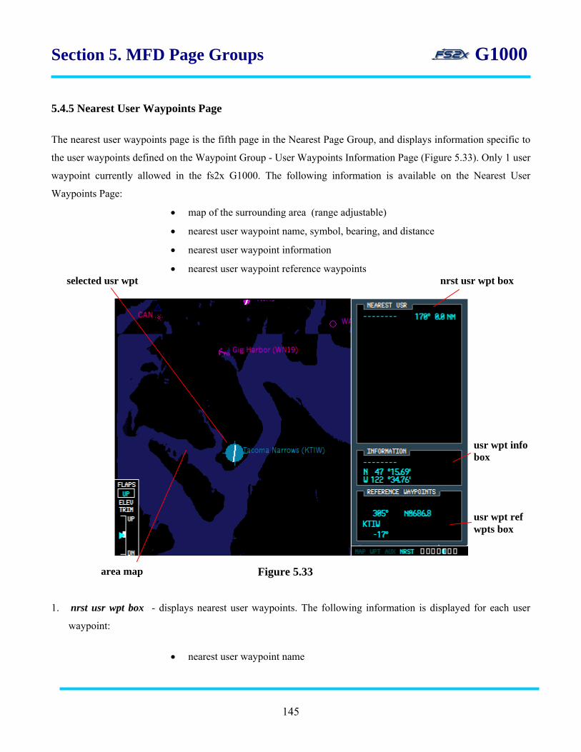
Section 5. MFD Page Groups G1000 5.4.5 Nearest User Waypoints Page
The nearest user waypoints page is the fifth page in the Nearest Page Group, and displays information specific to
the user waypoints defined on the Waypoint Group - User Waypoints Information Page (Figure 5.33). Only 1 user
waypoint currently allowed in the fs2x G1000. The following information is available on the Nearest User
Waypoints Page:
• map of the surrounding area (range adjustable)
• nearest user waypoint name, symbol, bearing, and distance
• nearest user waypoint information
• nearest user waypoint reference waypoints selected usr wpt nrst usr wpt box
usr wpt info box
usr wpt ref wpts box
Figure 5.33 area map
1. nrst usr wpt box - displays nearest user waypoints. The following information is displayed for each user
waypoint:
• nearest user waypoint name
145

Section 5. MFD Page Groups G1000
• nearest user waypoint bearing
• nearest user waypoint distance
2. nrst usr wpt info box - displays the following nearest user waypoint information:
Line 1 - displays the nearest user waypoint associated comment
Line 2 - displays the nearest user waypoint latitude
Line 3 - displays the nearest user waypoint longitude
3. nrst usr wpt ref wpts box - displays the following nearest user waypoint reference waypoints information:
Line 1 - displays the nearest primary user waypoint identifier
Line 2 - displays the nearest primary user waypoint bearing and distance
Line 3 - displays the nearest secondary user waypoint identifier
Line 4 - displays the nearest secondary user waypoint bearing
Instructions for using the Nearest User Waypoints page
1. click on the large FMS to go to the Nearest Page Group. The text ‘NRST’ in the Page Group Window will be
highlighted and the first rectangle will be filled in blue.
2. click on the small FMS to go to the Nearest User Waypoints page. The fifth rectangle will be filled in blue.
3. click on the FMS knob. The selected nearest user waypoint will be highlighted with a blinking cursor.
4. use the large FMS knob to scroll the cursor up and down the nearest user waypoints list.
5. click on the ENTER button to enter the highlighted selection, and to remove the blinking cursor. The selected
nearest user waypoint location and a surrounding area map of that user waypoint will be displayed. The
blinking cursor can also be removed by clicking on the FMS knob.
146
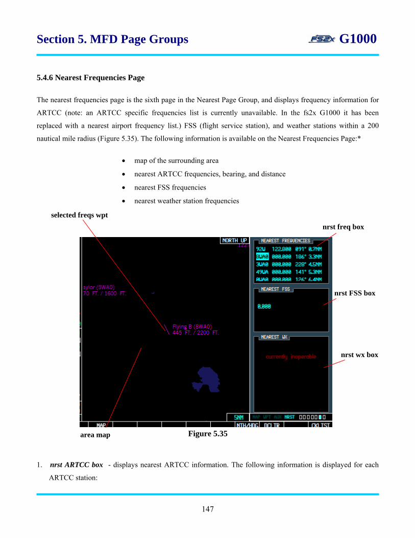
Section 5. MFD Page Groups G1000
5.4.6 Nearest Frequencies Page
The nearest frequencies page is the sixth page in the Nearest Page Group, and displays frequency information for
ARTCC (note: an ARTCC specific frequencies list is currently unavailable. In the fs2x G1000 it has been
replaced with a nearest airport frequency list.) FSS (flight service station), and weather stations within a 200
nautical mile radius (Figure 5.35). The following information is available on the Nearest Frequencies Page:*
• map of the surrounding area
• nearest ARTCC frequencies, bearing, and distance
• nearest FSS frequencies
• nearest weather station frequencies
selected freqs wpt
nrst freq box
nrst FSS box
nrst wx box
Figure 5.35 area map
1. nrst ARTCC box - displays nearest ARTCC information. The following information is displayed for each
ARTCC station:
147

Section 5. MFD Page Groups G1000
Line 1 - nearest ARTCC name
Line 2 - nearest ARTCC bearing
Line 3 - nearest ARTCC distance
Line 4 - nearest ARTCC frequency
2. nrst FSS box* - displays nearest FSS information. The following information is displayed for each FSS
station:
Line 1 - nearest FSS name
Line 2 - nearest FSS bearing
Line 3 - nearest FSS distance
Line 4 - nearest FSS frequency
3. nrst wx box* - displays the station identifier, type, and frequency of the 8 nearest weather service stations.
Instructions for using the Nearest Frequencies page
1. click on the large FMS to go to the Nearest Page Group. The text ‘NRST’ in the Page Group Window will be
highlighted and the first rectangle will be filled in blue.
2. click on the small FMS to go to the Nearest Frequencies page. The sixth rectangle will be filled in blue.
3. use the large FMS knob to scroll the cursor up and down the Nearest frequencies list.
4. nearest Frequency station
4.1 click on the FMS knob. The selected nearest frequency name will be highlighted with a blinking
cursor.
4.2 use the large FMS knob to scroll the cursor up and down the ARTCC stations list.
4.3 click on the ENTER button to enter the highlighted selection, and to remove the blinking cursor. The
selected nearest frequency station and a surrounding area map of that station will be displayed. The
blinking cursor can also be removed by clicking on the FMS knob.
148

Section 5. MFD Page Groups G1000
5.4.7 Nearest Airspaces Page
The nearest airspaces page is the seventh and final page in the Nearest Page Group, and displays airspace
information up to a maximum of 20 controlled airspaces (Figure 5.36). The following information is available on
the Nearest Airspaces Page:
• map of the surrounding area
• nearest airspaces alerts
• nearest selected airspace agency
• nearest selected airspace vertical limits
• nearest selected airspace frequencies nrst airspace alerts box selected airspace
nrst airspace agency box
nrst airspace vert limit box
nrst airspace freqs box
Figure 5.36 area map
1. nrst airspace alerts box - displays information about the nearest airspaces. Displays 3 out of a possible 20
nearest airspaces at one time; the other airspaces are displayed by scrolling through the list. The following
information is displayed for each airspace:
149
Section 5. MFD Page Groups G1000
• nearest airspace name
• nearest airspace status (relative location to the airspace)
• status displayed as ‘Ahead’ when <10nm, but >2nm from the airspace
• status displayed as ‘Ahead < 2nm’ when <2nm from the airspace
• status displayed as ‘Inside’ when the airspace is entered into
2. nrst airspace agency box* - the nearest airspace agency box displays the following information about the
selected the airspace and airspace agency:
Line 1 – nearest airspace type
Line 2 - nearest airspace controlling agency
3. nrst airspace vert limit box* - the nearest airspace vertical limit box displays the following information:
Line 1 – nearest airspace lowest altitude (floor)
Line 2 - nearest airspace highest altitude (ceiling)
3. nrst airspace freqs box - the nearest frequencies box displays the selected airspace name, associated
frequencies, and denotes if a particular frequency is ‘receive only’ (RX), ‘transmit only’ (TX), or both (no
denotation).
Instructions for using the Nearest Airspaces page
1. click on the large FMS to go to the Nearest Page Group. The text ‘NRST’ in the Page Group Window will be
highlighted and the first rectangle will be filled in blue.
2. click on the small FMS to go to the Nearest Airspaces page. The seventh rectangle will be filled in blue.
3. click on the FMS knob. The selected airspace will be highlighted with a blinking cursor.
4. use the large FMS knob to scroll the cursor up and down the airspaces list.
5. click on the FMS knob to remove the blinking cursor.
150
Section 6. Direct-To Navigation G1000 6. Direct-To Navigation (DTO) Page The Direct-To Navigation function provides a quick and convenient method to set a GPS course from the present
aircraft position directly to a destination waypoint. The G1000 establishes a direct point-to-point course using
‘Great Circle’ bearing and distance calculations. Course guidance is provided until the DTO function is cancelled
or the destination waypoint is changed. There are 5 ways to enter a destination waypoint from the PFD, and 6
ways from the MFD:
1. entering an ICAO code
2. entering a waypoint name
3. choosing from a flight plan waypoints list
4. choosing from a list of nearest airports
5. entering from the nearest airports page (PFD) or any of the nearest pages (MFD)
6. entering from the waypoint airport page (MFD only)
The DTO function is available from both the PFD and MFD by clicking on their respective DTO button. The
popup DTO Window displays the following in each (except where noted):
• destination waypoint identification information
• FPL associated information
• nearest airport associated information
• VNV altitude and distance values
• adjustable range inset map of the area surrounding the selected destination waypoint
(MFD only)
• destination waypoint location information
• destination waypoint course-to display
• an ‘ACTIVATE?’ field to activate the selected DTO function
6.1 MFD DTO page The DTO page window on the MFD displays 5 data boxes (Figure 6.1):
151

Section 6. Direct-To Navigation G1000 selected dep apt
1. ident, facility, city box – used to enter a destination waypoint by entering an ICAO code or waypoint name.
Line 1 - data field used to enter and display a selected destination waypoint by ICAO identifier
code.
Line 2 - data field used to enter and display a selected destination waypoint by facility name.
Line 3 – displays the name of the city closest to the selected destination waypoint.
2. VNV box – used to display and enter VNV altitude and distance values.
• VNV altitude field (left data field) – used to display, set or change VNV altitude value.
• VNV distance field (right data field) - used to display, set or change VNV distance value.
3. map box – inset map of area surrounding the selected destination waypoint. The map range value is listed in
the bottom right corner, and is changeable using the MFD Range Knob.
Figure 6.1
DTO ident box
VNV box
DTO location box
DTO crs box
map box
DTO activation field
152

Section 6. Direct-To Navigation G1000
4. location box – displays information related to the destination waypoint.
Line 1 – displays magnetic bearing to the selected destination waypoint in degrees.
Line 2 (left data field) - displays distance to the selected destination waypoint in nautical miles.
Line 2 (right data field) – displays the latitude and longitude coordinates of the selected
destination waypoint.
5. course box – displays the ‘course-to’ direction to navigate directly to the destination waypoint.
6. ACTIVATE field – when highlighted with the blinking cursor it is used to activate DTO navigation directly to
the selected destination waypoint.
Instructions for using the MFD DTO navigation page
1. click on the DTO button to display the DTO page window (Figure 6.1).
2. to select a destination waypoint by entering an ICAO identifier code:
2.1 with the ICAO highlighted, click on the right small FMS knob to highlight the first character in the
ICAO field. It will initially be highlighting the ICAO identifier field (ident/facility/city box – Line 1).
2.2 use the small FMS knob, or PC keyboard, to enter the ICAO identifier code of the desired destination
waypoint.
2.3 click the ENTER button one time to highlight and display the selected identifier.
2.4 click on the ENTER button again to highlight the “ACTIVATE” field, or use the large FMS knob to
scroll the cursor through the DTO window fields.
2.5 click on the ENTER button again to activate DTO navigation to the selected destination waypoint.
3. to select a destination waypoint by entering a facility name
153
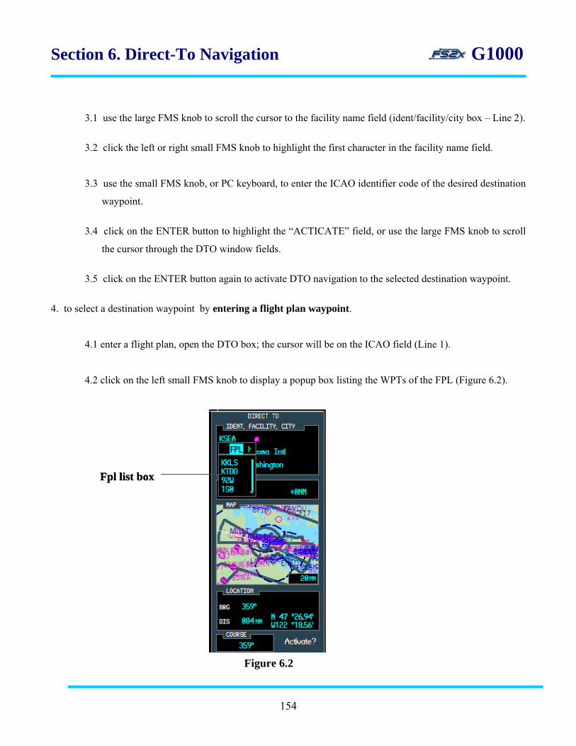
Section 6. Direct-To Navigation G1000
3.1 use the large FMS knob to scroll the cursor to the facility name field (ident/facility/city box – Line 2).
3.2 click the left or right small FMS knob to highlight the first character in the facility name field.
3.3 use the small FMS knob, or PC keyboard, to enter the ICAO identifier code of the desired destination
waypoint.
3.4 click on the ENTER button to highlight the “ACTICATE” field, or use the large FMS knob to scroll
the cursor through the DTO window fields.
3.5 click on the ENTER button again to activate DTO navigation to the selected destination waypoint.
4. to select a destination waypoint by entering a flight plan waypoint.
4.1 enter a flight plan, open the DTO box; the cursor will be on the ICAO field (Line 1).
4.2 click on the left small FMS knob to display a popup box listing the WPTs of the FPL (Figure 6.2).
Fpl list box Fpl list box
Figure 6.2
154

Section 6. Direct-To Navigation G1000
4.3 use the large FMS knob to scroll the cursor through the flight plan waypoints field. Note: once the
cursor has moved to a WPT in the fpl list the small FMS knob can be used to scroll through the list.
4.4 with the desired active flight plan waypoint highlighted, click on the ENTER button to enter the
choice as the DTO destination. This also closes the fpl window.
4.5 click on the ENTER button to highlight the “ACTIVATE” field or use the large FMS knob to scroll
the cursor to other fields.
4.6 click on the ENTER button again, when highlighted, to activate DTO navigation to the selected
destination waypoint.
5. to select a destination waypoint from a nearest airport list.
5.1 open the DTO box; the cursor will be on the ICAO field (Line 1).
5.2 click on the left small FMS knob to display the popup box listing the WPTs of the FPL. 5.3 when the FPL list header is highlighted (see Figure 6.2), click on the right small FMS knob to close
the fpl window and open the nearest airport list window (Figure 6.3).
155
Nearest Airport list box
Figure 6.3

Section 6. Direct-To Navigation G1000
5.4 use the large FMS knob to scroll the cursor through the flight plan waypoints field. Note: once the
cursor has moved to a nrst apt in the nrst apt list the small FMS knob can be used to scroll through the
list.
5.5 with the desired nearest airport highlighted, click on the ENTER button to enter the choice as the
DTO destination. This also closes the nearest airport list window.
5.6 click on the ENTER button to highlight the “ACTIVATE” field or use the large FMS knob to scroll
the cursor to other fields.
5.7 click on the ENTER button again, when highlighted, to activate DTO navigation to the selected
destination waypoint.
6. to select a destination waypoint from a nearest page.
6.1 use the right large FMS knob to go to the nearest page group.
6.2 use the small FMS knob to scroll to the appropriate nearest page.
6.3 click on the FMS knob to activate the cursor, and then scroll it to the desired waypoint.
6.4 click on the DTO button to enter the waypoint as the DTO waypoint.
7. to select a destination waypoint from the waypoint airport page.
7.1 use the right large FMS knob to go to the nearest page group.
7.2 click on the FMS knob to activate the cursor, and then scroll it to the airport ICAO field.
7.3 click on the DTO button to enter the displayed airport as the DTO waypoint.
8. use the left and right small FMS knob to toggle between the FPL and Nearest Airport windows.
9. click on the FMS knob at any time to close the blinking cursor.
10. click on the DTO button at any time to close the DTO window.
6.2 PFD DTO page
The DTO page window on the PFD displays the same DTO information as displayed on the MFD, except the
inset map (Figure 6.4). Likewise, the DTO destination waypoint can be entered in 4 ways, and the user is
prompted before activation. Activation of a DTO navigation plan supersedes all previous flight plans.
156

Section 6. Direct-To Navigation G1000
line 1
line 2 line 3
line 4 line 6
line 5
Figure 6.4 1. Line 1 - includes data field used to enter and/or display a selected destination waypoint by ICAO identifier
code. The following destination waypoint information is displayed:
• ICAO identifier code
• destination waypoint symbol
• closest city to the destination waypoint
2. Line 2 - data field used to enter and/or display a selected destination waypoint by facility name.
3a. Line 3 (left data field) - displays the VNV altitude value. Used to display, set, or change the VNV target
altitude.
3b. Line 3 (right data field) - displays the VNV distance value. Used to display, set, or change the VNV target
distance.
4a. Line 4 (left data field) - displays the bearing to the selected destination waypoint.
4b. Line 4 (right data field) - displays the selected destination waypoint latitude and longitude coordinates.
5. Line 5 - displays the distance in nautical miles to the selected destination waypoint.
6a. Line 6 (left data field) - displays the course-to bearing to the selected destination waypoint.
6b. Line 6 (right data field) - displays the ‘ACTIVE’ prompt for activating DTO navigation.
Instructions for using the PFD DTO navigation page
1. click on the DTO button to display the DTO page window (Figure 6.4).
2. to select a destination waypoint by entering an ICAO identifier code.
2.1 with the ICAO highlighted, click on the right small FMS knob to highlight the first character in the
ICAO field. It will initially be highlighting the ICAO identifier field (ident/facility/city box – Line 1).
157

Section 6. Direct-To Navigation G1000
2.2 use the small FMS knob, or PC keyboard, to enter the ICAO identifier code of the desired destination
waypoint.
2.3 click the ENTER button one time to highlight and display the selected identifier.
2.4 click on the ENTER button again to highlight the “ACTIVATE” field, or use the large FMS knob to
scroll the cursor through the DTO window fields.
2.5 click on the ENTER button again to activate DTO navigation to the selected destination waypoint.
3. to select a destination waypoint by entering a facility name;
3.1 use the large FMS knob to scroll the cursor to the facility name field (ident/facility/city box – Line 2).
3.2 click the left or right small FMS knob to highlight the first character in the facility name field.
3.3 use the small FMS knob, or PC keyboard, to enter the ICAO identifier code of the desired destination
waypoint.
3.4 click on the ENTER button to highlight the “ACTICATE” field, or use the large FMS knob to scroll
the cursor through the DTO window fields.
3.5 click on the ENTER button again to activate DTO navigation to the selected destination waypoint.
4. to select a destination waypoint by entering a flight plan waypoint.
4.1 enter a flight plan, open the DTO box; the cursor will be on the ICAO field (Line 1). 4.2 click on the left small FMS knob to display a popup box listing the WPTs of the FPL (Figure 6.5).
F pl list box
Figure 6.5
158
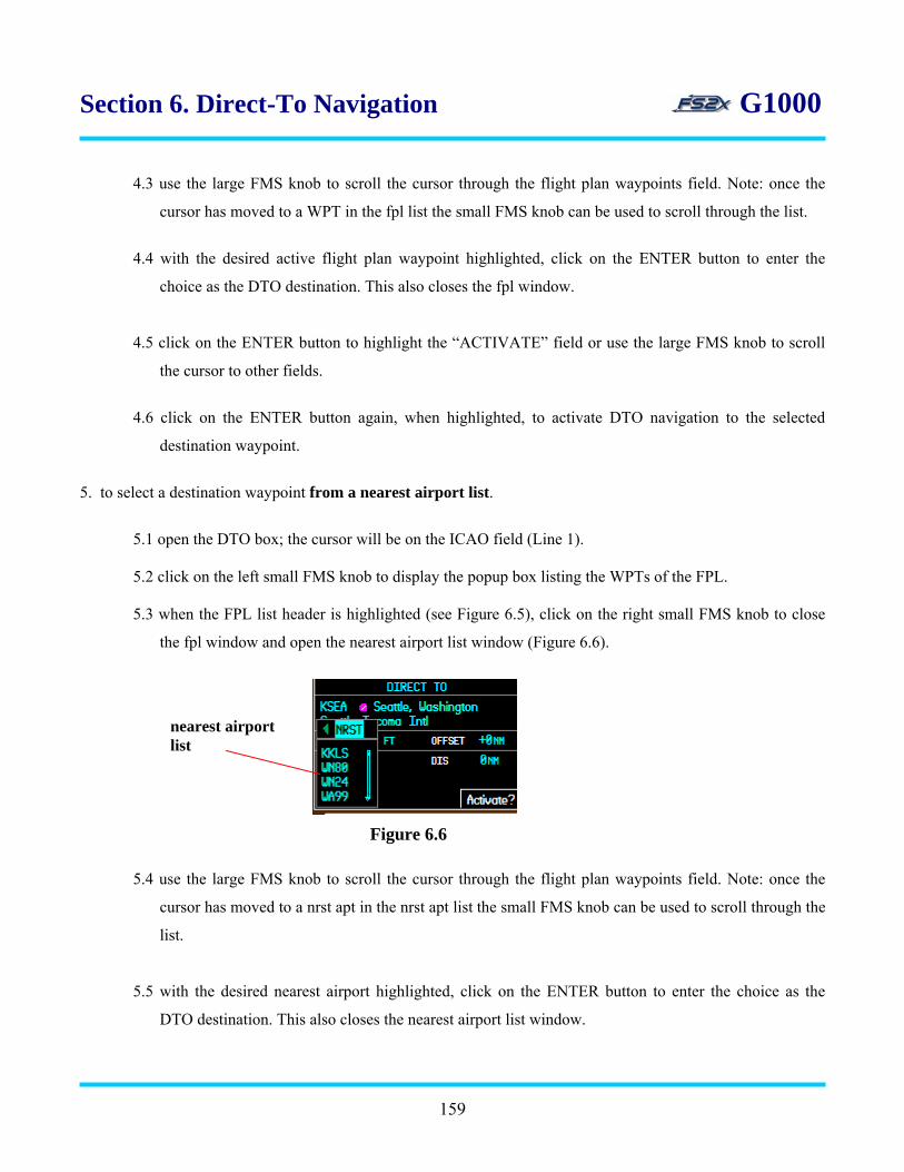
Section 6. Direct-To Navigation G1000 4.3 use the large FMS knob to scroll the cursor through the flight plan waypoints field. Note: once the
cursor has moved to a WPT in the fpl list the small FMS knob can be used to scroll through the list.
4.4 with the desired active flight plan waypoint highlighted, click on the ENTER button to enter the
choice as the DTO destination. This also closes the fpl window.
4.5 click on the ENTER button to highlight the “ACTIVATE” field or use the large FMS knob to scroll
the cursor to other fields.
4.6 click on the ENTER button again, when highlighted, to activate DTO navigation to the selected
destination waypoint.
5. to select a destination waypoint from a nearest airport list.
5.1 open the DTO box; the cursor will be on the ICAO field (Line 1).
5.2 click on the left small FMS knob to display the popup box listing the WPTs of the FPL. 5.3 when the FPL list header is highlighted (see Figure 6.5), click on the right small FMS knob to close
the fpl window and open the nearest airport list window (Figure 6.6).
5.4 use the large FMS knob to scroll the cursor through the flight plan waypoints field. Note: once the
cursor has moved to a nrst apt in the nrst apt list the small FMS knob can be used to scroll through the
list.
5.5 with the desired nearest airport highlighted, click on the ENTER button to enter the choice as the
DTO destination. This also closes the nearest airport list window.
Figure 6.6
nearest airport list
159
Section 6. Direct-To Navigation G1000
5.6 click on the ENTER button to highlight the “ACTIVATE” field or use the large FMS knob to scroll
the cursor to other fields.
5.7 click on the ENTER button again, when highlighted, to activate DTO navigation to the selected
destination waypoint.
6. to select a destination waypoint from the nearest page.
6.1 click on the NRST softkey to open the nearest page.
6.2 use the small FMS knob to scroll the cursor to the appropriate nearest airport.
6.3 click on the DTO button to enter the airport as the DTO waypoint.
7. use the left and right small FMS knob to toggle between the FPL and Nearest Airport windows.
8. click on the FMS knob at any time to close the blinking cursor.
9. click on the DTO button at any time to close the DTO window.
160

Section 7. Flight Planning G1000 7. Flight Planning (FPL) Page Group
The MFD FPL Group consists of 2 pages, and the PFD FPL Group consists of 1 page. Displayed information and
functions common to both groups include the following:
• flight plan title
• waypoints list
• active leg indicator
• desired track
• leg distance
• create a flight plan
• delete a flight plan
• add and delete waypoints
• load, change, or remove an approach
• changes fields
• restore defaults
• vertical navigation
Flight Plans can be accessed from 3 locations:
• PFD active flight plan page
• MFD active flight plan page
• MFD catalogue page Menu window
Flight plans can be entered in 4 ways:
• direct ICAO
• facility name
• flight plan waypoints list
• nearest airports list
When an approach is loaded into the active flight plan, a set of approach waypoints is inserted into the flight plan
list along with a header describing the selected procedure. The original enroute portion of the flight plan remains
active.
161

Section 7. Flight Planning G1000
7.1 MFD Flight Plan Page Group
The MFD FPL Group consists of the following 2 pages:
• active flight plan page
• flight plan catalogue page
When an MFD FPL window is displayed, the standard Page Group Window at the bottom right is replaced with a
FPL group window displaying the term ‘FPL’ and 2 rectangular page boxes (Figure 7.1). The selected FPL Group
page is indicated by the cyan color filled box.
fpl group window page group window Figure 7.1
The first flight plan page is the active flight plan page. The active FPL page can be displayed in a ‘narrow’ or
‘wide’ view format.
The second FPL page is the FPL Catalog page where flight plans are created, stored, edited, and retrieved from.
(note: only 1 flight plan currently available)
When the FPL window is open, certain softkeys change functionality specific to the flight plan pages (Figure 7.2).
These pages are discussed in detail below.
1. VIEW - used to display the 2nd level FPL softkeys where the user can choose to view the active flight plan
page in a narrow (default) or wide screen display (see below; Figure 7.x).
2. V PROF - used to access the vertical navigation page.
3. CNCL V - used to cancel vertical navigation page.
4. V DTO - used to access the vertical navigation page
Figure 7.2
1 2 3 4 5
162

Section 7. Flight Planning G1000
5. ATKOFST – used to initiate setting target altitudes and distances for VNV.
7.1.1 MFD active FPL flight plan page
The active flight plan page is used to create and edit flight plans, and to set VNV parameters. There is also a
popup menu window to further edit functions such as the deletion of a flight plan and/or approach, and to change
several display fields. The active flight plan page can be viewed in a narrow or wide view display.
A. narrow view
The narrow view of the active flight plan page is on by default (Figure 7.3).
#2 data fieldVNV target distance fields #3 data field
There are 4 information boxes displaying the following:
• active flight plan title
Figure 7.3
fpl title box
wpt info box
Vnv profile info box
VNV target altitude fields
#1 data field
#4 data field
163
Section 7. Flight Planning G1000
• waypoint information
• active leg information
• flight plan information
• VNV information
1. fpl title box - displays the title of the active flight plan. The flight plan title, by default, is given as the
ICAO identifier of the departure waypoint / ICAO identifier of the final destination waypoint, but can
be changed by the user on this page (does not change the title listed on the fpl catalogue page).
2. wpt info box - displays the following waypoint information:
• waypoints ICAO identifier
• wpt information listed in 3 data fields
• approach information
The #2 and #3 data fields displayed in the wpt info box are set by default to list the bearing and distance
between legs, however either field can be changed by the user to display any of the following parameters:
• distance (DIS)
• desired track (TRK)
• cumulative distance (CUM)
• estimated time enroute (ETE)
• estimated time of arrival (ETA)
• enroute safe altitude (ESA)
The waypoint information box also displays an approach header and associated approach waypoints when an
approach procedure is loaded.
3. current vnv box - displays the following information (see Section 9. Vertical Navigation):
3.1 Line 1 – displays the target altitude, VNV ICAO, and distance.
3.2 Line 2 – displays the desired VS and associated flight plan angle to use during VNV functioning.
164

Section 7. Flight Planning G1000
3.3 Line 3– displays the required VS, time to TOD (top of descent), and time to BOD (bottom of
descent).
3.4 Line 4 – displays the current deviation in VS from the desired VS.
B. wide view
The wide view of the active flight plan page (Figure 7.4) is accessed via the FPL ‘VIEW’ ‘WIDE’ softkeys.
The wide view FPL display lists most of the same FPL information listed on the narrow view FPL, but in addition
lists several fuel related parameters, including the amount of fuel remaining at each FPL wpt and the amount of
flight time remaining at each wpt based on the current fuel amount and fuel flow. The ETE and ETA for each leg
of the flight plan is also displayed.
VNV target distance fieldsWPT distance fields
fpl title
WPT bearing fields
VNV target altitude fields
wpt info box
Vnv profile info boxFigure 7.4
165

Section 7. Flight Planning G1000 1. fpl title box - displays the title of the active flight plan. The flight plan title, by default, is given as the
ICAO identifier of the departure waypoint / ICAO identifier of the final destination waypoint.
2. wpt info box - displays the following waypoint information:
• waypoints ICAO identifier
• FPL information listed in 7 data fields
• approach information
1. DTK - lists the direct-to bearing in degrees true north from one wpt to the next wpt. 2. DIS - lists the leg or cumulative distance in nautical miles from one wpt to the next wpt. 3. ALT – lists the entered target altitudes for vertical navigation in feet (MSL).
4. FUEL REM – lists the gallons of fuel remaining at each wpt based on the current amount (on the left). Lists
the remaining flight time at each wpt based on fuel amount and fuel flow (on the right).
5. ETE - lists the leg or cumulative estimated time enroute.
6. ETA - lists the estimated time of arrival at each waypoint.
7. BRG - lists the bearing in degrees true north from the aircraft position to the next wpt.
8. VNV target distance – lists the entered target distances for vertical navigation in nautical miles. 7.1.1.1 MFD flight plan entering and editing from the active flight plan page
When the FPL Page is opened, a list of waypoints, or nearest facility if no wpts have been entered, and a dashed
line below the list are displayed (Figures 7.3 and 7.4). Waypoint entry is done through a Waypoint Information
popup window and can be entered in 4 ways. Waypoints can be added to any location in the flight plan; they are
added in order directly above a highlighted wpt, or directly above the dashed line if highlighted. Waypoints can
also be deleted from this page. Waypoint entry and editing is performed in the same manner from both the narrow
and wide view displays.
166

Section 7. Flight Planning G1000
Instructions for entering and editing a flight plan
1. click on the FPL button to display the FPL page window (Figure 7.3).
2. click on the FMS knob to display the cursor.
3. to select a destination waypoint by entering an ICAO identifier code.
2.1 click on the right small FMS knob to display the Waypoint Information window (Figure 7.5).
ICAO code, airport name, and airport city
map of wpt surrounding area
3.2 with the ICAO highlighted, click on the right small FMS knob to highlight the first character in the
ICAO field. It will initially be highlighting the ICAO identifier field.
3.3 use the small FMS knob, or PC keyboard, to enter the ICAO identifier code of the desired destination
waypoint.
3.4 click the ENTER button one time to enter the wpt into the flight plan.
3.5 click the ENTER button again to close the Waypoint Information window and return to the FPL Page
window.
Figure 7.5
Bearing and distance from previous wpt
WPT latitude and longitude
167
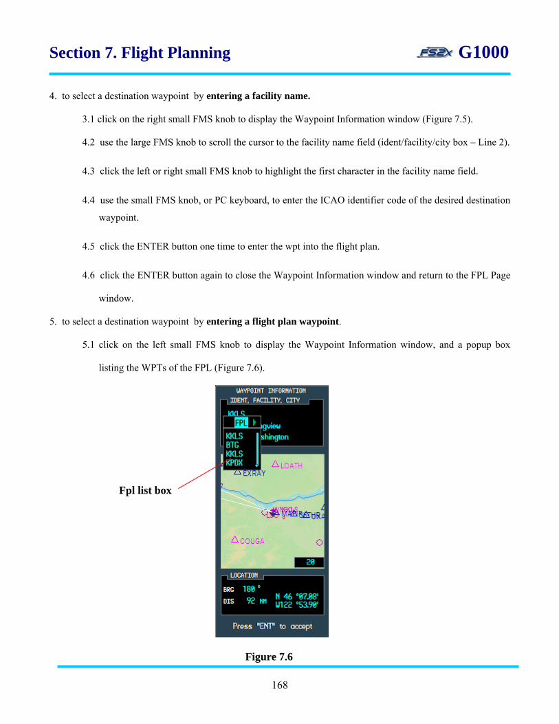
Section 7. Flight Planning G1000
4. to select a destination waypoint by entering a facility name.
3.1 click on the right small FMS knob to display the Waypoint Information window (Figure 7.5).
4.2 use the large FMS knob to scroll the cursor to the facility name field (ident/facility/city box – Line 2).
4.3 click the left or right small FMS knob to highlight the first character in the facility name field.
4.4 use the small FMS knob, or PC keyboard, to enter the ICAO identifier code of the desired destination
waypoint.
4.5 click the ENTER button one time to enter the wpt into the flight plan.
4.6 click the ENTER button again to close the Waypoint Information window and return to the FPL Page
window.
5. to select a destination waypoint by entering a flight plan waypoint.
5.1 click on the left small FMS knob to display the Waypoint Information window, and a popup box
listing the WPTs of the FPL (Figure 7.6).
Fpl list box
Figure 7.6
168

Section 7. Flight Planning G1000
5.2 use the large FMS knob to scroll the cursor through the flight plan waypoints field. Note: once the
cursor has moved to a WPT in the fpl list the small FMS knob can be used to scroll through the list.
5.3 with the desired active flight plan waypoint highlighted, click on the ENTER button to enter the wpt
choice and close the fpl list window.
5.4 click on the ENTER button again to close the Waypoint Information window and return to the FPL
Page Window.
6. to select a destination waypoint from a nearest airport list.
6.1 click on the left small FMS knob to display the Waypoint Information window, and a popup box
listing the WPTs of the FPL (Figure 7.6).
6.2 click on the right small FMS knob to close the fpl wpt window and open a popup box listing the
nearest 25 airports (Figure 7.7).
NRST apt list box
Figure 7.7
169

Section 7. Flight Planning G1000
6.3 use the large FMS knob to scroll the cursor through the nearest apt list. Note: once the cursor has
moved to a WPT in the fpl list the small FMS knob can be used to scroll through the list.
6.4 with the desired nrst apt highlighted, click on the ENTER button to enter the choice and close the nrst
apt list window.
6.5 click on the ENTER button again to close the Waypoint Information window and return to the FPL
Page Window.
7. to add a wpt to the end of the fpl, scroll the cursor to the dashed line field and then click the small FMS to open
the Waypoint Information window.
8. to add a wpt anywhere except the end of the fpl, scroll the cursor to the wpt immediately following the intended
location. Click the small FMS to open the Waypoint Information window.
9. to delete a waypoint from the active fpl page:
9.1 scroll the cursor using the large FMS knob until the appropriate wpt is highlighted.
9.2 click on the CLR button to popup a remove window (Figure 7.8).
Figure 7.8
9.3 click on the right large FMS knob to move the cursor to the CANCEL field, and on the left large
FMS knob to move it to the OK field.
9.4 click on the ENT button deletion when OK is highlighted to approve the.
9.5 click on the ENT button when CANCEL is highlighted to cancel the deletion.
170

Section 7. Flight Planning G1000
7.1.1.2 MFD active flight plan page Menu window
Further flight plan editing can be done from the active flight plan page via a popup menu window (Figure 7.9).
Figure 7.9
The edit options available on the fs2x G1000 MFD active flight plan window are displayed in bright cyan in
figure 7.3. The darkened options are not currently available; however they are included for future consideration.
The available options are discussed below in order from top to bottom.
1. activate leg - used to change the active leg of a fpl. Select any waypoint in the fpl, enter it, and it becomes the
next waypoint in the flight plan. Navigation to the waypoint begins immediately.
2. delete flight plan - used to delete the active flight plan. All waypoints are erased.
3. load approach - used to load, or load and activate, an instrument approach for the active flight plan.
4. remove approach - used to remove an instrument approach from the active flight plan.
5. change fields - used to change the flight plan parameters displayed in data fields #2 and #3.
6. restore defaults - sets the flight plan parameters displayed in data fields #2 and #3 to the default display of
DTK and DIS, respectively.
171

Section 7. Flight Planning G1000
Instructions for using the MFD FPL active flight plan Menu window
1. click on the FPL button to open the FPL Page, and then on the FMS knob to activate the cursor.
2. click on the MENU button to open the Menu window (Figure 7.9).
3. use the large FMS knob to scroll the blinking cursor vertically through the choices.
4. when the desired function is highlighted, click on the ENTER key to activate it.
5. click on the FMS knob to close the menu window.
6. use the activate leg function.
6.1 with the active flight plan window closed, click on the FMS knob to highlight the blinking cursor.
6.2 use the large FMS knob to scroll the cursor to the fpl waypoint you want to activate as the new direct-
to waypoint.
6.3 click on the MENU key to display the active flight plan page window.
6.4 use the large FMS knob to scroll the cursor to the activate leg field.
6.5 click on the ENTER key to display the activate leg window. The selected leg chosen will be displayed
in the window, along with the course bearing and a blinking prompt to ACTIVATE or CANCEL the
selection (Figure 7.10). selected leg
6.6 use the large FMS knob to toggle the blinking cursor between the ACTIVATE and CANCEL
fields.
Figure 7.10 activate/cancel prompts
course bearing
172

Section 7. Flight Planning G1000
6.7 click on the ENTER key when a field is highlighted to perform the designated function. Clicking the
ENTER key also closes the activate leg window and returns the user to the active flight plan page
window.
6.8 click the large FMS knob to close the active flight plan page window and return to the active flight
plan page.
7. use the delete flight plan function.
7.1 click on the MENU key to display the active flight plan page window.
7.2 use the large FMS knob to scroll the cursor to the delete flight plan field.
7.3 click on the ENTER key to display a window prompting to perform the function or cancel (Figure
7.11).
Figure 7.11
7.4 use the large FMS knob to toggle the blinking cursor between the OK and CANCEL fields.
7.5 click on the ENTER key when a field is highlighted to perform the designated function. Clicking the
ENTER key also closes the delete flight plan window and returns the user to the active flight plan
page window.
7.6 click the large FMS knob to close the active flight plan page window and return to the active flight
plan page.
8. use the load approach function.
8.1 click on the MENU key to display the active flight plan page window.
8.2 use the large FMS knob to scroll the cursor to the load approach field.
8.3 click on the ENTER key to display the approach procedure window. This is the same approach
procedure window that is displayed when loading an approach from the Procedure Page. Clicking on
173
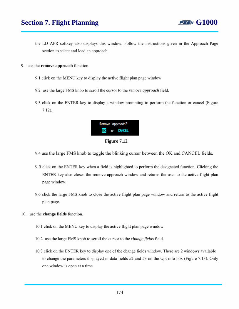
Section 7. Flight Planning G1000
the LD APR softkey also displays this window. Follow the instructions given in the Approach Page
section to select and load an approach.
9. use the remove approach function.
9.1 click on the MENU key to display the active flight plan page window.
9.2 use the large FMS knob to scroll the cursor to the remove approach field.
9.3 click on the ENTER key to display a window prompting to perform the function or cancel (Figure
7.12).
Figure 7.12
9.4 use the large FMS knob to toggle the blinking cursor between the OK and CANCEL fields.
9.5 click on the ENTER key when a field is highlighted to perform the designated function. Clicking the
ENTER key also closes the remove approach window and returns the user to the active flight plan
page window.
9.6 click the large FMS knob to close the active flight plan page window and return to the active flight
plan page.
10. use the change fields function.
10.1 click on the MENU key to display the active flight plan page window.
10.2 use the large FMS knob to scroll the cursor to the change fields field.
10.3 click on the ENTER key to display one of the change fields window. There are 2 windows available
to change the parameters displayed in data fields #2 and #3 on the wpt info box (Figure 7.13). Only
one window is open at a time.
174

Section 7. Flight Planning G1000
wpt info box data field #3
10.4 use the large FMS knob to change from one window to the other, and the small FMS knob to scroll
through the fields in the window.
10.5 click on the ENTER key to enter the highlighted selection. This also closes the change fields window
and returns the user to the active flight plan page window.
10.6 click the large FMS knob to close the active flight plan page window and return to the active flight
plan page.
11. use the restore defaults function.
11.1 click on the MENU key to display the active flight plan page window.
11.2 use the large FMS knob to scroll the cursor to the restore defaults field.
11.3 click on the ENTER key to display a window prompting to perform the function or cancel (Figure
7.14).
Figure 7.13
data field #2 window data field #3 window
data field #2
Figure 7.14
175
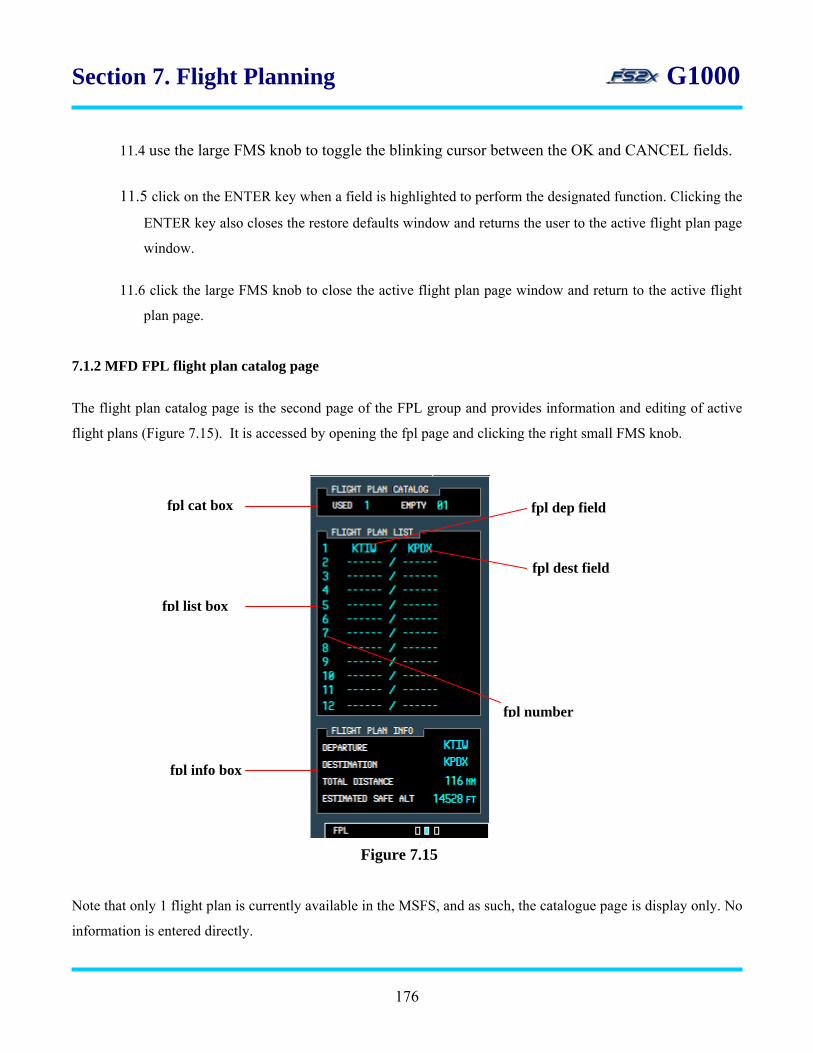
Section 7. Flight Planning G1000
11.4 use the large FMS knob to toggle the blinking cursor between the OK and CANCEL fields.
11.5 click on the ENTER key when a field is highlighted to perform the designated function. Clicking the
ENTER key also closes the restore defaults window and returns the user to the active flight plan page
window.
11.6 click the large FMS knob to close the active flight plan page window and return to the active flight
plan page.
7.1.2 MFD FPL flight plan catalog page
The flight plan catalog page is the second page of the FPL group and provides information and editing of active
flight plans (Figure 7.15). It is accessed by opening the fpl page and clicking the right small FMS knob.
fpl cat box fpl dep field
Note that only 1 flight plan is currently available in the MSFS, and as such, the catalogue page is display only. No
information is entered directly.
Figure 7.15
fpl list box
fpl info box
fpl number
fpl dest field
176

Section 7. Flight Planning G1000
There are 3 information boxes displaying the following:
• flight plan catalog status
• list of stored flight plans
• information about the selected flight plan
1. fpl cat box - displays the number of stored flight plans (USED field, left) and the remaining number of flight
plans that can be stored (EMPTY field, right).
2. fpl list box - displays the following flight plan information:
• fpl number
• departure waypoint identifier
• destination waypoint identifier
3. fpl info box - the following flight plan information:
3.1 Line 1 – displays the departure waypoint identifier
3.2 Line 2 – displays the destination waypoint identifier
3.3 Line 3 – displays the cumulative (total) distance of the selected flight plan
3.4 Line 4 – displays the estimated safe altitude for the selected flight plan
7.1.2.1 MFD FPL flight plan catalog page MENU
Flight plan editing from the flight plan catalog page is performed using newly displayed softkeys (Figure 7.16),
and a popup menu window (Figure 7.17). softkeys unique to the fpl catalog page
Figure 7.16
177

Section 7. Flight Planning G1000
The following softkeys are unique to the fpl catalog page and allows the user to open a page directly without
having to go through the fpl catalog window:
1. active softkey - used to go directly to the active flight plan page.
2. edit softkey - used to edit the active flight plan waypoints.
3. ld apr softkey - used to load, or load and activate, an instrument approach for the active flight plan.
Figure 7.17
The edit options available on the fs2x G1000 flight plan catalog window are displayed in bright cyan in figure
7.17. The darkened options are not currently available; however they are included for future consideration. The
available options are discussed below in order from top to bottom.
1. create flight plan - used in the fs2x G1000 to go to the FPL Page window.
2. edit flight plan - used to edit active flight plans.
178

Section 7. Flight Planning G1000 3. delete flight plan - used to delete an active flight plan.
Instructions for using the MFD FPL flight plan catalog page
1. click on the FPL button. If the FPL group is not on the flight plan catalog page, use the small FMS knob to
scroll to it. There are no user directly changeable fields on the fpl catalog page.
2. use the softkeys to change flight plan parameters.
2.1 click on 1 of the unique softkeys to open the corresponding page window and follow the instructions
listed below for the same function through the menu window.
3. use the fpl catalog menu window to change flight plan parameters.
3.1 click on the MENU key when the active flight plan page is open. The flight plan catalog menu
window is displayed (Figure 7.17).
3.2 use the large FMS knob to scroll the blinking cursor vertically through the choices.
3.3 when the desired function is highlighted, click on the ENTER key to activate it.
3.4 click on the FMS knob to close the menu window.
4. use the create flight plan function.
4.1 click on the MENU key to display the flight plan catalog page menu window.
4.2 use the large FMS knob to scroll the cursor to the create flight plan field.
4.3 click on the ENTER key to display a window prompting to perform the function or cancel (Figure
7.18).
4.4 use the large FMS knob to toggle the blinking cursor between the OK and CANCEL fields.
Figure 7.18
creat
179
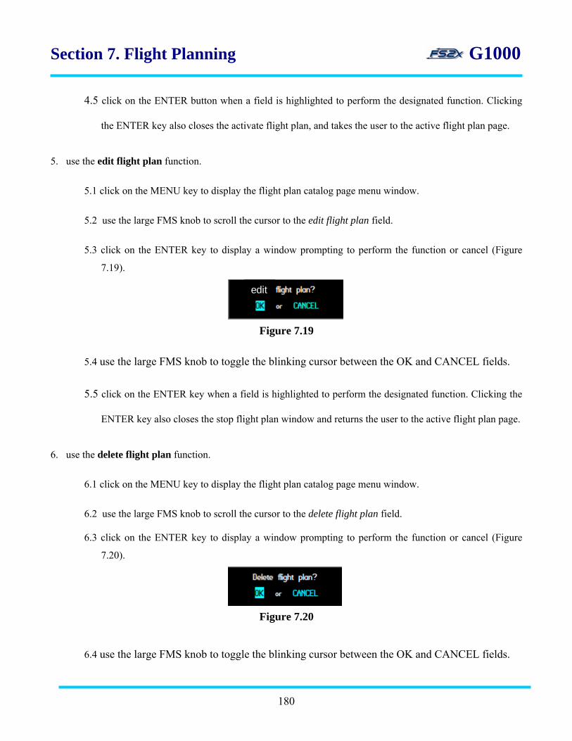
Section 7. Flight Planning G1000
4.5 click on the ENTER button when a field is highlighted to perform the designated function. Clicking
the ENTER key also closes the activate flight plan, and takes the user to the active flight plan page.
5. use the edit flight plan function.
5.1 click on the MENU key to display the flight plan catalog page menu window.
5.2 use the large FMS knob to scroll the cursor to the edit flight plan field.
5.3 click on the ENTER key to display a window prompting to perform the function or cancel (Figure
7.19).
edit
Figure 7.19
5.4 use the large FMS knob to toggle the blinking cursor between the OK and CANCEL fields.
5.5 click on the ENTER key when a field is highlighted to perform the designated function. Clicking the
ENTER key also closes the stop flight plan window and returns the user to the active flight plan page.
6. use the delete flight plan function.
6.1 click on the MENU key to display the flight plan catalog page menu window.
6.2 use the large FMS knob to scroll the cursor to the delete flight plan field.
6.3 click on the ENTER key to display a window prompting to perform the function or cancel (Figure
7.20).
6.4 use the large FMS knob to toggle the blinking cursor between the OK and CANCEL fields.
180
Figure 7.20
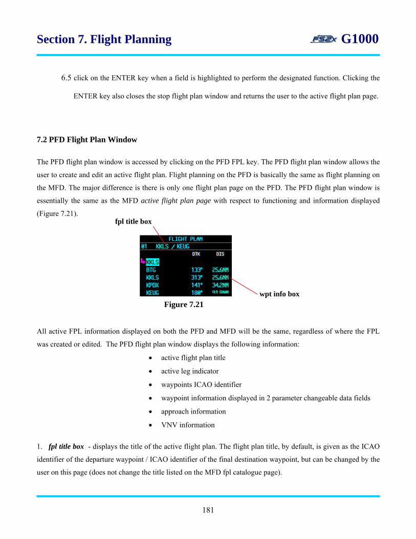
Section 7. Flight Planning G1000
6.5 click on the ENTER key when a field is highlighted to perform the designated function. Clicking the
ENTER key also closes the stop flight plan window and returns the user to the active flight plan page.
7.2 PFD Flight Plan Window
The PFD flight plan window is accessed by clicking on the PFD FPL key. The PFD flight plan window allows the
user to create and edit an active flight plan. Flight planning on the PFD is basically the same as flight planning on
the MFD. The major difference is there is only one flight plan page on the PFD. The PFD flight plan window is
essentially the same as the MFD active flight plan page with respect to functioning and information displayed
(Figure 7.21).
fpl title box
wpt info box Figure 7.21
All active FPL information displayed on both the PFD and MFD will be the same, regardless of where the FPL
was created or edited. The PFD flight plan window displays the following information:
• active flight plan title
• active leg indicator
• waypoints ICAO identifier
• waypoint information displayed in 2 parameter changeable data fields
• approach information
• VNV information
1. fpl title box - displays the title of the active flight plan. The flight plan title, by default, is given as the ICAO
identifier of the departure waypoint / ICAO identifier of the final destination waypoint, but can be changed by the
user on this page (does not change the title listed on the MFD fpl catalogue page).
181

Section 7. Flight Planning G1000
2. wpt info box - displays the following waypoint information:
• waypoints ICAO identifier
• wpt information listed in 2 data fields
• approach information
The #2 and #3 data fields displayed in the wpt info box are set by default to list the bearing and distance
between legs, however either field can be changed by the user to display any of the following parameters:
• distance (DIS)
• desired track (TRK)
• cumulative distance (CUM)
• estimated time enroute (ETE)
• estimated time of arrival (ETA)
The waypoint information box also displays an approach header and associated approach waypoints when an
approach procedure is loaded (Figure 22).
approach info
Figure 7.22
7.2.1 PFD flight plan entering and editing from the active flight plan page
Flight planning from the PFD active flight plan page is the same procedure as used for the MFD (see pgs 67-70).
A wpt, or dashed line, is highlighted and the small FMS knob is used to display a Waypoint Information page.
Waypoints can be added to the fpl as in the MFD by 4 different methods (see pg 61).
• ICAO entry
• Facility name entry
• Fpl wpt list choice
• Nrst apt list choice
Waypoints are added direct before the highlighted wpt. Deleting a waypoint is also done in the same manner as
with the MFD (see pg 70).
182

Section 7. Flight Planning G1000
7.2.2 PFD flight plan page Menu window
The PFD flight plan window has a MENU window associated with it that is used to edit flight plan parameters
(Figure 7.23). This window displays the same options, in the same order, as displayed on the MFD fpl page
group/active flight plan page window (all options are viewable by scrolling).
Figure 7.23
The edit options available on the fs2x G1000 PFD flight plan window are displayed in bright cyan in Figure 7.19.
The darkened options are not currently available; however they are included for future consideration. The
available options are discussed below in order from top to bottom.
1. activate leg - used to change the active leg of a fpl. Select any waypoint in the fpl, enter it, and it becomes the
next waypoint in the flight plan. Navigation to the waypoint begins immediately.
2. delete flight plan - used to delete the active flight plan. All waypoints are erased.
3. load approach - used to load, or load and activate, an instrument approach for the active flight plan.
4. remove approach - used to remove an instrument approach from the active flight plan.
Instructions for using the PFD flight plan menu
1. click the FPL button.
2. use the large FMS knob to scroll through the fields.
3. click on the ENTER button when a field is highlighted to activate that function.
4. use the activate leg function.
4.1 with the active flight plan window closed, click on the FMS knob to highlight the blinking cursor.
183

Section 7. Flight Planning G1000
.4.2 use the large FMS knob to scroll the cursor to the fpl waypoint you want to activate as the new
direct- to waypoint.
4.3 click on the MENU key to display the active flight plan page window.
4.4 use the large FMS knob to scroll the cursor to the activate leg field.
4.5 click on the ENTER key to display the activate leg window. The selected leg chosen will be displayed
in the window, along with the course bearing and a blinking prompt to ACTIVATE or CANCEL the
selection (Figure 7.24).
selected leg
4.6 use the large FMS knob to toggle the blinking cursor between the ACTIVATE and CANCEL
fields.
4.7 click on the ENTER key when a field is highlighted to perform the designated function. Clicking the
ENTER key also closes the activate leg window and returns the user to the PFD fpl menu window.
4.8 click the large FMS knob to close the PFD fpl menu window and return to the PFD flight plan
window.
5. use the delete flight plan function.
5.1 click on the MENU key to display the active flight plan page window.
5.2 use the large FMS knob to scroll the cursor to the delete flight plan field.
5.3 click on the ENTER key to display a window prompting to perform the function or cancel (Figure
7.25).
Figure 7.24 activate/cancel prompts
course bearing
184
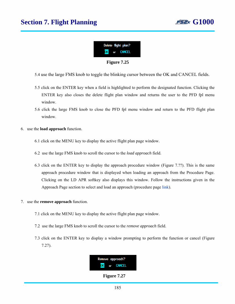
Section 7. Flight Planning G1000
Figure 7.25
5.4 use the large FMS knob to toggle the blinking cursor between the OK and CANCEL fields.
5.5 click on the ENTER key when a field is highlighted to perform the designated function. Clicking the
ENTER key also closes the delete flight plan window and returns the user to the PFD fpl menu
window.
5.6 click the large FMS knob to close the PFD fpl menu window and return to the PFD flight plan
window.
6. use the load approach function.
6.1 click on the MENU key to display the active flight plan page window.
6.2 use the large FMS knob to scroll the cursor to the load approach field.
6.3 click on the ENTER key to display the approach procedure window (Figure 7.??). This is the same
approach procedure window that is displayed when loading an approach from the Procedure Page.
Clicking on the LD APR softkey also displays this window. Follow the instructions given in the
Approach Page section to select and load an approach (procedure page link).
7. use the remove approach function.
7.1 click on the MENU key to display the active flight plan page window.
7.2 use the large FMS knob to scroll the cursor to the remove approach field.
7.3 click on the ENTER key to display a window prompting to perform the function or cancel (Figure
7.27).
Figure 7.27
185

Section 7. Flight Planning G1000
7.4 use the large FMS knob to toggle the blinking cursor between the OK and CANCEL fields.
7.5 click on the ENTER key when a field is highlighted to perform the designated function. Clicking the
ENTER key also closes the remove approach window and returns the user to the PFD fpl menu
window.
186
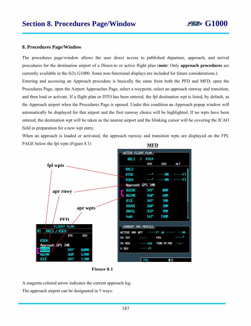
Section 8. Procedures Page/Window G1000 8. Procedures Page/Window The procedures page/window allows the user direct access to published departure, approach, and arrival
procedures for the destination airport of a Direct-to or active flight plan (note: Only approach procedures are
currently available in the fs2x G1000. Some non-functional displays are included for future considerations.).
Entering and accessing an Approach procedure is basically the same from both the PFD and MFD; open the
Procedures Page, open the Airport Approaches Page, select a waypoint, select an approach runway and transition,
and then load or activate. If a flight plan or DTO has been entered, the fpl destination wpt is listed, by default, as
the Approach airport when the Procedures Page is opened. Under this condition an Approach popup window will
automatically be displayed for that airport and the first runway choice will be highlighted. If no wpts have been
entered, the destination wpt will be taken as the nearest airport and the blinking cursor will be covering the ICAO
field in preparation for a new wpt entry.
When an approach is loaded or activated, the approach runway and transition wpts are displayed on the FPL
PAGE below the fpl wpts (Figure 8.1)
A magenta colored arrow indicates the current approach leg.
The approach airport can be designated in 5 ways:
187
MFD
PFD
fpl wpts
apr rnwy
apr wpts
Figure 8.1

Section 8. Procedures Page/Window G1000
• automatically if fpl or dto entered
• entering an ICAO designation
• entering the airport name
• selecting from a fpl list
• selecting from a nearest airport list
8.1 MFD Procedures Pages
The MFD procedures page (Figure 8.2) can be opened by simply clicking on the MFD PROC key. Alternatively,
it can be opened from the fpl Catalogue Page.
Figure 8.2
The MFD procedures page is used to select or activate a published instrument approach for the destination airport,
or to replace the current instrument approach.
There are 4 functional choices on this page:
1. SELECT APPROACH – used to open the Airport Approaches Page.
2. ACTIVATE VECTOR-TO-FINAL - used to activate vector transition approaches.
188
options box
loaded box

G1000 Section 8. Procedures Page/Window
3. ACTIVATE APPROACH - used to activate non-vectored transition approaches.
4. ACTIVATE MISSED APPROACH – used to activate the missed approach procedure.
If an approach has not been loaded or activated, opening the Procedures Page will result in the display shown in
Figure 8.2, with the SELECT APPROACH field highlighted and the 3 ACTIVATE field’s dimmed (SELECT
ARRIVAL, DEPARTURE, and MISSED APPROACH functions not available). If an approach has been loaded
when the Procedures Page is opened, the ACTIVATE fields will be cyan colored and the cursor will be covering
the first or second ACTIVATE fields, depending on the approach type (Figure 8.3). If an approach has been
activated and the Procedures Page is opened, the cursor will be highlighting the ACTIVATE MISSED
APPROACH. The APPROACH field in the ‘loaded box’ will list the approach airport ICAO and runway when an
approach is loaded or activated.
Figure 8.3
The ACTIVATE fields allow the user to activate an approach without having to go through the approach and
transition fields selection again. Loading an approach procedure enters the procedure into the active flight plan,
189

Section 8. Procedures Page/Window G1000
but does not affect current navigation. Once the approach is activated however, the aircraft will immediately begin
to navigate the approach procedure.
A loaded approach can be replaced at any time by choosing the SELECT APPROACH function from the MFD
procedures page.
8.1.1 Instructions for using the MFD Procedures Page
1. click on the MFD PROC button to open the Procedures Page.
2. use the large FMS knob to scroll through the choices. The first 2 activate fields are not available until an
approach is loaded or activated. The activate missed approach field is not active until an approach has been
activated.
4. when the desired field is highlighted click on the ENTER button to initiate the function.
5. click on the PROC button or the FMS knob to close the Procedures Page.
8.2 MFD Airport Approach Page
The SELECT APPROACH option is used to open the MFD Airport Approach Page where the user selects a
published approach procedure for a destination airport (Figure 8.4). Choosing an approach includes designating
the approach airport, runway, and transition. When an approach and transition have been selected and entered, the
user can then choose to load or activate the entered procedure. If the approach airport is entered when a FPL or
DTO has not been entered, only the ACTIVATE function is available.
190

Section 8. Procedures Page/Window G1000
apt box
apr box
trans box
freq box
seq box
act field load field
Figure 8.45
1. apt box - displays the following information about the destination airport.
• airport ICAO identifier code
• airport type symbol
• airport user designation
• airport name
• airport closest city, state
2. apr box - displays the selected approach for the destination airport. The approach is selected from a popup list
of published approach procedures for the destination airport.
3. trans box - displays the selected transition for the selected approach procedure. The transition is selected from
a popup list of published transition procedures for the destination airport.
4. freq box - displays the approach frequency of the destination airport.
191
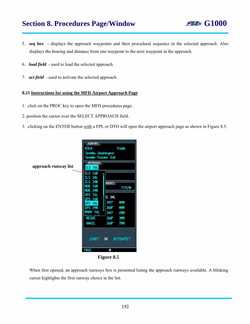
Section 8. Procedures Page/Window G1000
5. seq box - displays the approach waypoints and their procedural sequence in the selected approach. Also
displays the bearing and distance from one waypoint to the next waypoint in the approach.
6. load field - used to load the selected approach.
7. act field - used to activate the selected approach.
8.21 Instructions for using the MFD Airport Approach Page
1. click on the PROC key to open the MFD procedures page.
2. position the cursor over the SELECT APPROACH field.
3. clicking on the ENTER button with a FPL or DTO will open the airport approach page as shown in Figure 8.5.
approach runway list
Figure 8.5
When first opened, an approach runways box is presented listing the approach runways available. A blinking
cursor highlights the first runway choice in the list.
192

Section 8. Procedures Page/Window G1000
3.1 use the large or small fms knobs to scroll the cursor through the approach airport runways list.
3.2 click on the ENTER key with an approach runway highlighted to select that runway. The runway
window will close and an approach transition box listing the available transitions is displayed (Figure
8.6).
approach transition list
Figure 8.6
3.3 use the small or large FMS knobs to scroll through the transition list.
3.4 click on the ENTER key with a transition highlighted to select that transition. The transition window will
close and the cursor will shift to the LOAD? field.
3.5 click the ENTER button to load the approach or click on the right large FMS knob to shift the cursor to
the ACTIVATE field. In either case, clicking on the ENTER button when either field is highlighted will
lead to the steps described below (steps 3.7-3.8.2).
3.6 click on the ENTER key to display a ‘chosen’ runway window (Figure 87).
Figure 8.7
193
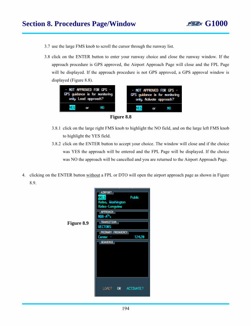
Section 8. Procedures Page/Window G1000
3.7 use the large FMS knob to scroll the cursor through the runway list.
3.8 click on the ENTER button to enter your runway choice and close the runway window. If the
approach procedure is GPS approved, the Airport Approach Page will close and the FPL Page
will be displayed. If the approach procedure is not GPS approved, a GPS approval window is
displayed (Figure 8.8).
Figure 8.8
3.8.1 click on the large right FMS knob to highlight the NO field, and on the large left FMS knob
to highlight the YES field.
3.8.2 click on the ENTER button to accept your choice. The window will close and if the choice
was YES the approach will be entered and the FPL Page will be displayed. If the choice
was NO the approach will be cancelled and you are returned to the Airport Approach Page.
4. clicking on the ENTER button without a FPL or DTO will open the airport approach page as shown in Figure
8.9.
Figure 8.9
194
Section 8. Procedures Page/Window G1000
When first opened, the nearest airport is highlighted in the ICAO field in preparation to enter a different
airport. An approach airport can be entered in 1 of 4 ways as described earlier in the DTO and FPL sections.
• direct ICAO entry
• airport name entry
• choose from a fpl list
• choose from a nearest airport list
Instructions for entering an approach airport
1. to select a destination waypoint by entering an ICAO identifier code.
1.1 with the ICAO highlighted, click on the right small FMS knob to highlight the first character in the
ICAO field. It will initially be highlighting the ICAO identifier field.
1.2 use the small FMS knob, or PC keyboard, to enter the ICAO identifier code of the desired approach
airport.
1.3 click the ENTER button to enter the choice as the approach airport.
2. to select a destination waypoint by entering a facility name.
2.1 use the large FMS knob to scroll the cursor to the facility name field (Line 3).
2.2 click the left or right small FMS knob to highlight the first character in the facility name field.
2.3 use the small FMS knob, or PC keyboard, to enter the ICAO identifier code of the approach airport.
2.4 click the ENTER button to enter the choice as the approach airport.
3. to select a destination waypoint by entering a flight plan waypoint.
3.1 click on the left small FMS knob to display a popup box listing the WPTs of the FPL (Figure 8.10).
195

Section 8. Procedures Page/Window G1000
Fpl list box
Figure 8.10
3.2 use the large FMS knob to scroll the cursor through the flight plan waypoints field. Note: once the
cursor has moved to a WPT in the fpl list the small FMS knob can be used to scroll through the list.
3.3 with the desired active flight plan waypoint highlighted, click on the ENTER button to enter the
approach airport choice and close the fpl list window.
4. to select a destination waypoint from a nearest airport list.
4.1 click on the right small FMS knob to close the fpl wpt window and open a popup box listing the
nearest 25 airports (Figure 8.11).
4.2 use the large FMS knob to scroll the cursor through the nearest apt list. Note: once the cursor has
moved to a WPT in the fpl list the small FMS knob can be used to scroll through the list.
196
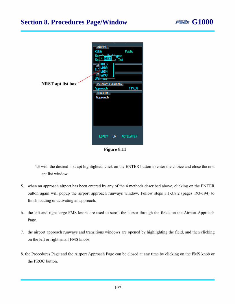
Section 8. Procedures Page/Window G1000
4.3 with the desired nrst apt highlighted, click on the ENTER button to enter the choice and close the nrst
apt list window.
5. when an approach airport has been entered by any of the 4 methods described above, clicking on the ENTER
button again will popup the airport approach runways window. Follow steps 3.1-3.8.2 (pages 193-194) to
finish loading or activating an approach.
6. the left and right large FMS knobs are used to scroll the cursor through the fields on the Airport Approach
Page.
7. the airport approach runways and transitions windows are opened by highlighting the field, and then clicking
on the left or right small FMS knobs.
8. the Procedures Page and the Airport Approach Page can be closed at any time by clicking on the FMS knob or
the PROC button.
Figure 8.11
NRST apt list box
197

Section 8. Procedures Page/Window G1000
8.3 PFD Procedures Page
The PFD Procedures and Airport Approach Pages are used to enter, load, and activate a published approach
procedure for the destination airport in exactly the same manner as the MFD page. As such, a detailed description
of pages, displays, steps, and instructions are not included in this section. See section 8.1. Only differences
between the MFD and PFD will be discussed here.
The PFD procedures window is opened by clicking the PROC key on the PFD (Figure 8.12).
The select approach option is used to open the PFD Airport Approach Page where the user selects a published
approach procedure for the destination airport (Figure 8.13).
line 1 line 2
line 3 line 4
line 5 line 6
Figure 8.13
1. line 1 - displays the destination airport identifier, symbol, and closest city.
2. line 2 - displays the destination airport name.
3. line 3 - displays the selected approach name.
4. line 4 - displays the selected transition name.
5. line 5 - displays the frequency and frequency identifier of the selected approach.
Figure 8.12
198
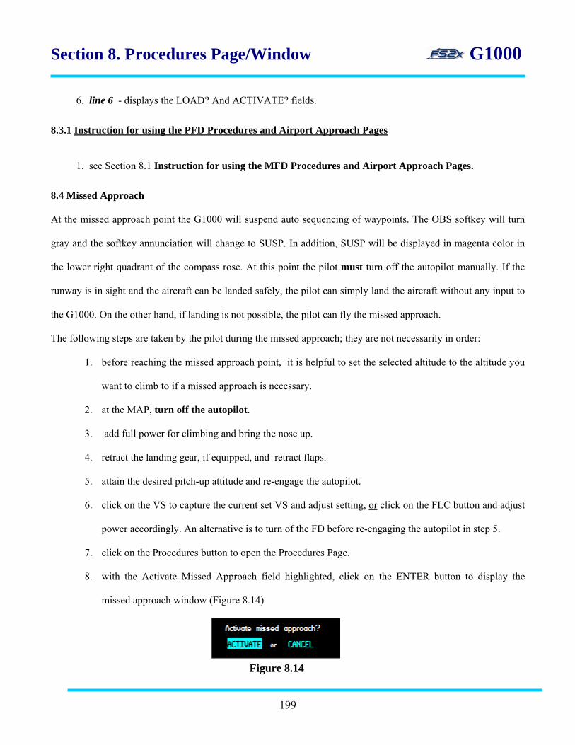
Section 8. Procedures Page/Window G1000
6. line 6 - displays the LOAD? And ACTIVATE? fields.
8.3.1 Instruction for using the PFD Procedures and Airport Approach Pages
1. see Section 8.1 Instruction for using the MFD Procedures and Airport Approach Pages.
8.4 Missed Approach
At the missed approach point the G1000 will suspend auto sequencing of waypoints. The OBS softkey will turn
gray and the softkey annunciation will change to SUSP. In addition, SUSP will be displayed in magenta color in
the lower right quadrant of the compass rose. At this point the pilot must turn off the autopilot manually. If the
runway is in sight and the aircraft can be landed safely, the pilot can simply land the aircraft without any input to
the G1000. On the other hand, if landing is not possible, the pilot can fly the missed approach.
The following steps are taken by the pilot during the missed approach; they are not necessarily in order:
1. before reaching the missed approach point, it is helpful to set the selected altitude to the altitude you
want to climb to if a missed approach is necessary.
2. at the MAP, turn off the autopilot.
3. add full power for climbing and bring the nose up.
4. retract the landing gear, if equipped, and retract flaps.
5. attain the desired pitch-up attitude and re-engage the autopilot.
6. click on the VS to capture the current set VS and adjust setting, or click on the FLC button and adjust
power accordingly. An alternative is to turn of the FD before re-engaging the autopilot in step 5.
7. click on the Procedures button to open the Procedures Page.
8. with the Activate Missed Approach field highlighted, click on the ENTER button to display the
missed approach window (Figure 8.14)
Figure 8.14
199

Section 8. Procedures Page/Window G1000
7. use the large right FMS knob to move the cursor to the CANCEL field and the large left FMS knob
to move the cursor to the ACTIVATE field.
8. click on the ENTER button when the choice is highlighted to initiate the function and close the
window.
9. alternatively, click on the OBS softkey instead of performing steps 5-8.
10. either procedure will activate the missed approach.
11. when the missed approach has been activated, the OBS softkey will return to the default state and
the magenta SUSP annunciation on the compass rose will be replaced by a magenta color MAPR
annunciation displayed in the upper right quadrant. The MAPR annunciation will be displayed until
the next waypoint has been reached.
11. click the NAV button to start automatic sequencing of the missed approach waypoints.
200

Section 9. Vertical Navigation (VNV) G1000
9.1 Vertical navigation (VNV) page
The vertical navigation page is used to descend the aircraft from a set distance and altitude to a pre-defined
distance and altitude relative to a flight plan or DTO waypoint.
target altitude fields
target distance fields
Figure 9.21
VNV profile box
Figure 9.1 VNV target distance and altitude parameters can be set from 3 locations:
• active FPL Page on the MFD
• DTO Page on the MFD
• DTO Page on the PFD
The Current VNV Profile box is used to display the parameters required for VNV, and is only displayed
on the MFD active fpl page (narrow or wide view).
The general strategy of the VNV page is outlined below:
• select reference point from flight plan waypoints or DTO waypoint
• enter the distance from the reference point to the target point (before or after)
• enter the target point altitude
• select if the altitude entered is AGL or MSL
201

Section 9. Vertical Navigation (VNV) G1000
• enter the desired vertical speed or use the default FPA of 3 degrees
• set the Selected Altitude to at least 100 ft below the aircraft altitude
• activate the VNV mode
1. target distance fields – displays the distance from the waypoint to the target point in nautical miles.
Negative and positive values represent distances before and after the reference waypoint,
respectively, in nautical miles.
2. target altitude fields – displays the altitude of the target point above the altitude of the reference
waypoint in feet above MSL or AGL. The current VNV reference waypoint is indicated by a cyan
colored target altitude; non-current VNV reference waypoints display the target altitude in white
color.
3. VNV profile box – lists the VNV parameter values in the VNV mode.
Line 1. lists the current target altitude, reference waypoint ICAO, and target distance.
Line 2. lists the desired vertical speed (feet per minute) and flight plan angle (degrees). Both values
can be set by the user, or the user can use the default FPA of 3 degrees.
Line 3. lists the VS required to maintain the desired VS on the left side, and the time
(minutes:seconds) to reach the TOD (top of descent) and BOD (bottom of descent) on the right side.
The numerical value in the VS REQ field is displayed when the aircraft is within 1 minute of the
TOD and disappears when the BOD is reached. The TOD annunciation changes to BOD during the
descent. The required VS can also be set to display in the upper bar.
Line 4. lists the deviation of the current glide path in feet above or below the desired glide path. The
V DEV value is displayed from 1 minute to TOD until the BOD is reached.
9.1.1 Instructions for using the VNV mode from a flight plan (MFD only)
A. instructions for entering VNV parameters.
1. open the MFD FPL Page and enter a flight plan.
2. click on the FMS knob to activate the blinking cursor, if absent.
202
3. use the large fms knob to scroll the cursor to a waypoint to be referenced during VNV.
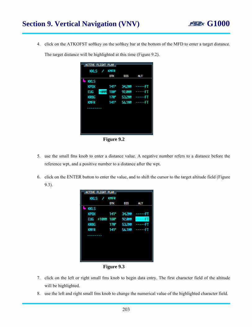
Section 9. Vertical Navigation (VNV) G1000
4. click on the ATKOFST softkey on the softkey bar at the bottom of the MFD to enter a target distance.
The target distance will be highlighted at this time (Figure 9.2).
Figure 9.2
5. use the small fms knob to enter a distance value. A negative number refers to a distance before the
reference wpt, and a positive number to a distance after the wpt.
6. click on the ENTER button to enter the value, and to shift the cursor to the target altitude field (Figure
9.3).
7. click on the left or right small fms knob to begin data entry. The first character field of the altitude
will be highlighted.
8. use the left and right small fms knob to change the numerical value of the highlighted character field.
203
Figure 9.3
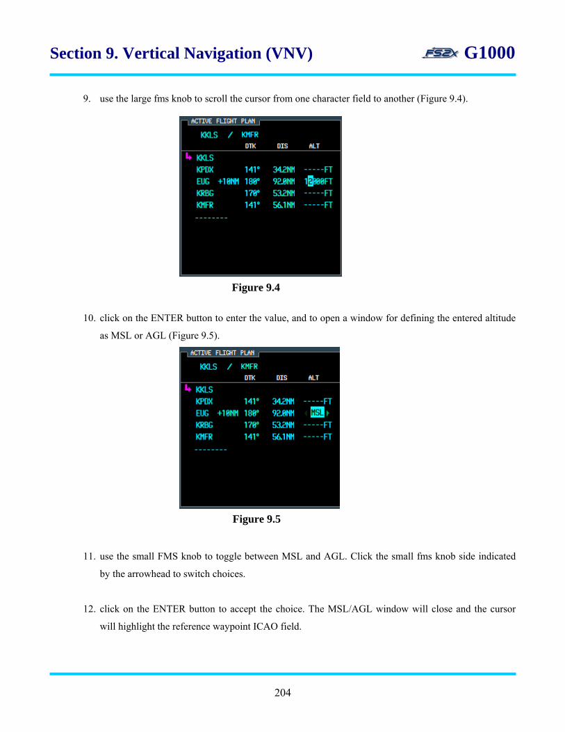
Section 9. Vertical Navigation (VNV) G1000
9. use the large fms knob to scroll the cursor from one character field to another (Figure 9.4).
Figure 9.4
10. click on the ENTER button to enter the value, and to open a window for defining the entered altitude
as MSL or AGL (Figure 9.5).
11. use the small FMS knob to toggle between MSL and AGL. Click the small fms knob side indicated
by the arrowhead to switch choices.
12. click on the ENTER button to accept the choice. The MSL/AGL window will close and the cursor
will highlight the reference waypoint ICAO field.
Figure 9.5
204

Section 9. Vertical Navigation (VNV) G1000
13. to enter another VNV profile, use the large FMS knob to scroll the cursor to a different wpt and
repeat steps 4-12.
14. note: the fs2x G1000 does not automatically scroll the cursor to the next reference wpt; the user must
manually scroll the cursor to the next reference wpt using the large fms knob.
B. instructions for using the VNV mode
1. with the VNV parameters entered and the desired reference wpt highlighted, click on the autopilot
VNV button to activate the VNV mode. Note: the VNV mode cannot be activated until the aircraft
altitude is above the VNV target altitude.
2. an activated VNV mode is indicated by a white VPTH annunciation on the right side of the PFD upper
bar display (Figure 9.6).
Figure 9.6
3. the VNV mode must be activated before the TOD is reached to capture the glide path. Note: for the
G1000 to capture the vertical path, the selected altitude must be set to at least 75 feet below the aircraft
current altitude before reaching the TOD.
4. if the VNV mode is activated within 5 minutes from the TOD, no additional user input is necessary.
5. if the VNV mode is activated before 5 minutes to TOD, the user must ‘verify’ activation of the VNV
mode within 5 minutes to the TOD. This can be done in 2 ways:
• clicking the autopilot VNV button
• lowering the selected altitude
6. if the user does not verify the VNV mode within 1 minute to the TOD, the VPTH annunciation on the
PFD display will start to blink and continue to blink until the TOD is reached, or until the user clicks on
the VNV button. Clicking on the VNV button before the TOD is reached will cancel the blinking cursor
and continue the VNV mode. If the VNV button is not clicked before reaching the TOD, the VNV
mode will be cancelled.
205
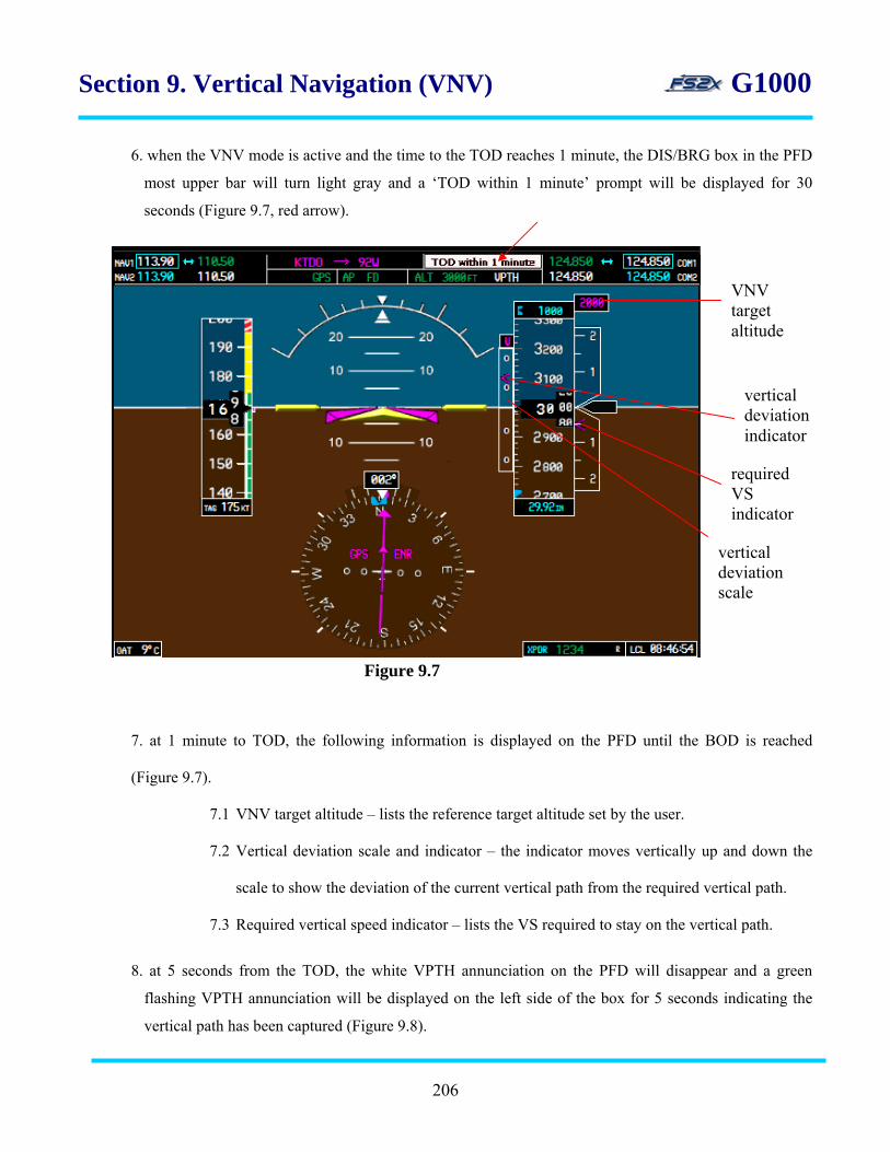
Section 9. Vertical Navigation (VNV) G1000
6. when the VNV mode is active and the time to the TOD reaches 1 minute, the DIS/BRG box in the PFD
most upper bar will turn light gray and a ‘TOD within 1 minute’ prompt will be displayed for 30
seconds (Figure 9.7, red arrow).
required VS indicator
vertical deviation indicator
VNV target altitude
vertical deviation scale
Figure 9.7
7. at 1 minute to TOD, the following information is displayed on the PFD until the BOD is reached
(Figure 9.7).
7.1 VNV target altitude – lists the reference target altitude set by the user.
7.2 Vertical deviation scale and indicator – the indicator moves vertically up and down the
scale to show the deviation of the current vertical path from the required vertical path.
7.3 Required vertical speed indicator – lists the VS required to stay on the vertical path.
8. at 5 seconds from the TOD, the white VPTH annunciation on the PFD will disappear and a green
flashing VPTH annunciation will be displayed on the left side of the box for 5 seconds indicating the
vertical path has been captured (Figure 9.8).
206

Section 9. Vertical Navigation (VNV) G1000
8. when the BOD is within 1 minute, the DIS/BRG box in the PFD most upper bar will turn light
gray and a ‘BOD within 1 minute’ prompt will be displayed for 30 seconds (Figure 9.9).
9. when the BOD is reached, the VNV mode and the PFD annunciations will be turned off.
10. to vertical navigate to another reference waypoint ahead, repeat the above process. The fs2x
G1000 will not automatically sequence to the next reference waypoint.
11. the current reference wpt is indicated by the position of the cursor and the target altitude
color in cyan.
9.1.2 Instructions for entering VNV parameters from the MFD and PFD DTO Page
The VNV target distance and altitude can be entered from the MFD or PFD DTO PAGES using the same approach.
• open the DTO page
• enter the waypoint ICAO
• scroll the cursor to the target altitude and/or target distance field
• enter the desired value
• activate DTO navigation
1. click on the DTO button to open the DTO window.
2. enter the reference waypoint ICAO as discussed in the DTO section.
3. the steps for entering the target altitude and distance are essentially the same as described
from the active flight plan page.
4. use the large fms knob to scroll the cursor to the target altitude field (Figure 9.10).
Figure 9.9
Figure 9.8
207

Section 9. Vertical Navigation (VNV) G1000
5. click on the small left or right fms knob to begin entering data. Use the small fms knob to
enter values, and the large fms knob to scroll between data fields.
6. when the target distance has been entered, click on the ENTER button to accept the value,
and to scroll the cursor to the target distance field.
7. use the left and right small fms knob to decrease and increase the value, respectively.
8. click on the ENTER button to accept the value and move the cursor to the ACTIVATE field.
9. click on the ENTER button again to activate DTO navigation.
10. the target altitude and distance value will be displayed in the MFD Current VNV Profile box
on the active flight page.
_____________________________________________________
Figure 9.10
target altitude field
PFD MFD
target distance field
208
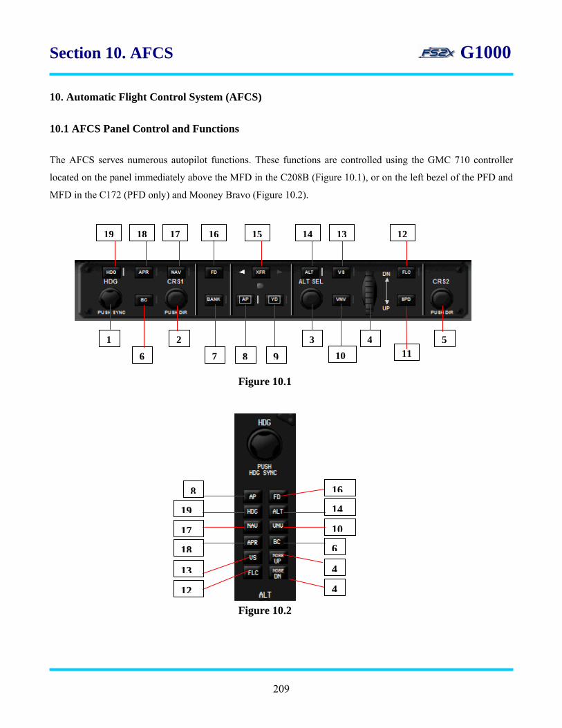
Section 10. AFCS G1000
10. Automatic Flight Control System (AFCS)
10.1 AFCS Panel Control and Functions
The AFCS serves numerous autopilot functions. These functions are controlled using the GMC 710 controller
located on the panel immediately above the MFD in the C208B (Figure 10.1), or on the left bezel of the PFD and
MFD in the C172 (PFD only) and Mooney Bravo (Figure 10.2).
1213141516171819
531 4
6 97 102
8 11
Figure 10.1
Figure 10.2
8
4
6
4
10
14
16
13
12
18
17
19
209

Section 10. AFCS G1000
All of the buttons (keys), except for the FD and SPD buttons, have an associated vertical white annunciation light
immediately to their right that is lit when the associated function is on, or active.
When an AFCS mode is armed a corresponding white colored annunciation is displayed in the AFCS Status bar
located at the top of the PFD display screen (Figure 10.3). The annunciation color changes to green when the
mode becomes active.
1. Heading Knob – selects the heading on the HSI as indicated by the heading bug. Click on the left side of the
knob to decrease the heading value, and on the right side to increase the value. While the heading value is
being changed, and for 3 seconds thereafter, a heading box is displayed on the left center of the PFD listing
the value numerically. Click on the knob to synchronize the heading bug with the aircraft heading. The
heading bug value is the aircraft heading set when the autopilot Heading mode is active.
2. CRS1 Knob – the CRS1 knob is used to select the course heading value when the HSI is in the VOR1, VOR2,
or OBS mode. Click on the left side of the knob to decrease the course value, and on the right side to increase
the value. While the course value is being changed, and for 3 seconds thereafter, a course heading box is
displayed on the right center of the PFD listing the value numerically. Click on the knob to center the CDI to
the current course.
3. Dual ALT Knob – sets the selected altitude used by the autopilot when in the autopilot Altitude mode. The
selected altitude is displayed in a box directly above the altimeter. Click on the large ALT knob (upper click
spots) to change the thousands and the small ALT knob (lower click spots) to change the hundreds. Click on
the knob to set the current aircraft altitude to the selected altitude.
4. FLC/VS Reference Wheel – used to select the reference values when in the FLC or VS mode. Increases and
decrease the airspeed when the FLC mode is active, and increases or decreases the vertical speed when in the
Figure 10.3
AFCS status bar
210

Section 10. AFCS G1000
VS mode. Click on the top of the wheel to decrease reference values, and on the bottom of the wheel to
increase the values.
5. CRS2 Knob – the large CRS2 knob (upper click spots) selects the course heading value when the HSI is in the
VOR1, VOR2, or OBS mode. Click on the knob to center the CDI to the current course. (the CRS2 knob is
used in the real world to change course values on the 2nd PFD (co-pilot). With the fs2x G1000 it has the same
function as the CRS1 knob.)
6. BC Key – activates/deactivates the Back Course mode. Allows the user to capture and track a localizer signal
in the backcourse direction. The selected course must be set to the localizer front course when making a
backcourse approach. The backcourse mode is indicated on the left side of the AFCS Status box by a green
colored ‘BC’ annunciation when activated.
7. Bank Key – When engaged the maximum bank angle is set at 15 degrees. Only available in Heading and Nav
modes (GPS and VOR).
8. AP Key – turns the autopilot ON and OFF. The Flight Director is also turned on when the autopilot is turned
on, and is on whenever the AP is on. The AP must be ON to activate any of the autopilot modes. A green
colored ‘AP’ annunciation is displayed in the AFCS Status bar when the AP is ON screen (Figure 10.2). The
AP annunciation turns to yellow when the AP is turned off, and flashes for 5 seconds before disappearing.
9. YD Key – activates/deactivates the yaw damper. A green colored ‘AP’ annunciation is displayed in the AFCS
Status bar when the YD is ON screen (Figure 10.2).
10. VNV Key – activates/deactivates the Vertical Navigation mode. Also used to verify an active VNV mode.
11. SPD Key – toggles the Reference Airspeed display (above the airspeed indicator tape on the PDF) between
IAS and Mach when in the FLC mode.
12. FLC Key – activates/deactivates the Flight Level Change mode. The FLC mode allows the user to ascend or
descend to the Selected Altitude at a constant airspeed by simply adjusting the power. For example, during a
descent the less power you have the steeper the angle, or larger negative VS value, you need to maintain the
constant airspeed. In this case, one result is a shorter descent distance.
211
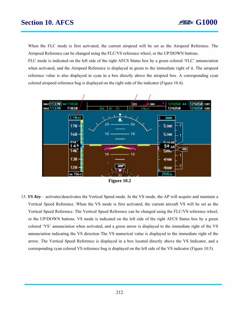
Section 10. AFCS G1000
When the FLC mode is first activated, the current airspeed will be set as the Airspeed Reference. The
Airspeed Reference can be changed using the FLC/VS reference wheel, or the UP/DOWN buttons.
FLC mode is indicated on the left side of the right AFCS Status box by a green colored ‘FLC’ annunciation
when activated, and the Airspeed Reference is displayed in green to the immediate right of it. The airspeed
reference value is also displayed in cyan in a box directly above the airspeed box. A corresponding cyan
colored airspeed reference bug is displayed on the right side of the indicator (Figure 10.4).
Figure 10.2
13. VS Key – activates/deactivates the Vertical Speed mode. In the VS mode, the AP will acquire and maintain a
Vertical Speed Reference. When the VS mode is first activated, the current aircraft VS will be set as the
Vertical Speed Reference. The Vertical Speed Reference can be changed using the FLC/VS reference wheel,
or the UP/DOWN buttons. VS mode is indicated on the left side of the right AFCS Status box by a green
colored ‘VS’ annunciation when activated, and a green arrow is displayed to the immediate right of the VS
annunciation indicating the VS direction The VS numerical value is displayed to the immediate right of the
arrow. The Vertical Speed Reference is displayed in a box located directly above the VS Indicator, and a
corresponding cyan colored VS reference bug is displayed on the left side of the VS indicator (Figure 10.5).
212
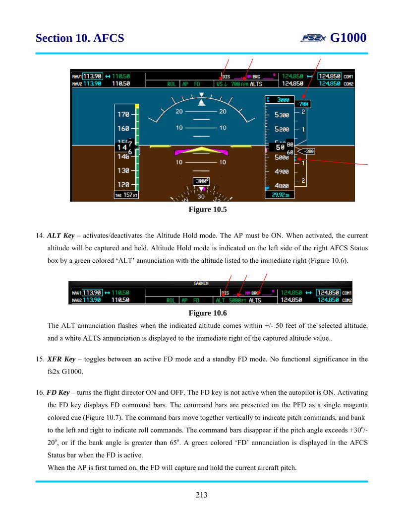
Section 10. AFCS G1000
Figure 10.5
14. ALT Key – activates/deactivates the Altitude Hold mode. The AP must be ON. When activated, the current
altitude will be captured and held. Altitude Hold mode is indicated on the left side of the right AFCS Status
box by a green colored ‘ALT’ annunciation with the altitude listed to the immediate right (Figure 10.6).
Figure 10.6
The ALT annunciation flashes when the indicated altitude comes within +/- 50 feet of the selected altitude,
and a white ALTS annunciation is displayed to the immediate right of the captured altitude value..
15. XFR Key – toggles between an active FD mode and a standby FD mode. No functional significance in the
fs2x G1000.
16. FD Key – turns the flight director ON and OFF. The FD key is not active when the autopilot is ON. Activating
the FD key displays FD command bars. The command bars are presented on the PFD as a single magenta
colored cue (Figure 10.7). The command bars move together vertically to indicate pitch commands, and bank
to the left and right to indicate roll commands. The command bars disappear if the pitch angle exceeds +30o/-
20o, or if the bank angle is greater than 65o. A green colored ‘FD’ annunciation is displayed in the AFCS
Status bar when the FD is active.
When the AP is first turned on, the FD will capture and hold the current aircraft pitch.
213
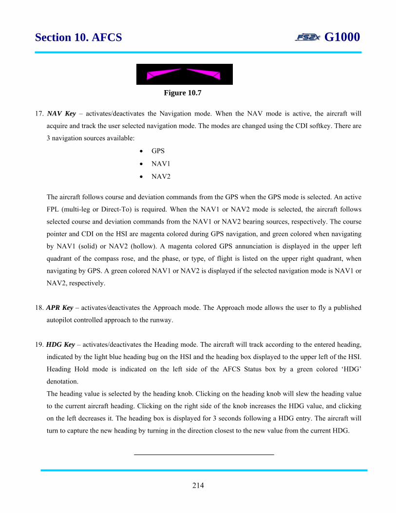
Section 10. AFCS G1000
17. NAV Key – activates/deactivates the Navigation mode. When the NAV mode is active, the aircraft will
acquire and track the user selected navigation mode. The modes are changed using the CDI softkey. There are
3 navigation sources available:
• GPS
• NAV1
• NAV2
The aircraft follows course and deviation commands from the GPS when the GPS mode is selected. An active
FPL (multi-leg or Direct-To) is required. When the NAV1 or NAV2 mode is selected, the aircraft follows
selected course and deviation commands from the NAV1 or NAV2 bearing sources, respectively. The course
pointer and CDI on the HSI are magenta colored during GPS navigation, and green colored when navigating
by NAV1 (solid) or NAV2 (hollow). A magenta colored GPS annunciation is displayed in the upper left
quadrant of the compass rose, and the phase, or type, of flight is listed on the upper right quadrant, when
navigating by GPS. A green colored NAV1 or NAV2 is displayed if the selected navigation mode is NAV1 or
NAV2, respectively.
18. APR Key – activates/deactivates the Approach mode. The Approach mode allows the user to fly a published
autopilot controlled approach to the runway.
19. HDG Key – activates/deactivates the Heading mode. The aircraft will track according to the entered heading,
indicated by the light blue heading bug on the HSI and the heading box displayed to the upper left of the HSI.
Heading Hold mode is indicated on the left side of the AFCS Status box by a green colored ‘HDG’
denotation.
The heading value is selected by the heading knob. Clicking on the heading knob will slew the heading value
to the current aircraft heading. Clicking on the right side of the knob increases the HDG value, and clicking
on the left decreases it. The heading box is displayed for 3 seconds following a HDG entry. The aircraft will
turn to capture the new heading by turning in the direction closest to the new value from the current HDG.
Figure 10.7
214

Section 11. Audio Panel G1000
11. Audio Panel
11. 1 Audio Panel Controls and Functions The G1000 audio panel is part of a communications/navigation/surveillance system that also includes the
communication radios, navigation radios, and the mode S transponder (Figure 11.1). It is a stand-alone unit
typically located between the PFD and MFD. The audio panel is used to select a number of audio functions of the
transmitter and receiver audio system. These functions include the following active functions in the fs2x G1000:
• COM microphone transmitter selection
• COM audio receiver selection
• marker beacon receiver audio selection
• NAV audio receiver selection
1 2
3 4
65
7 8
9 10
11 12
13 14
15 16
17
Figure 11.1
1918
20 21
22 23
24
215

Section 11. Audio Panel G1000
1. COM1 MIC - selects COM1 for transmitting. Automatically and simultaneously selects the COM1 receiver
for audio reception.
2. COM1 - selects the COM1 receiver for audio reception.
3. COM2 MIC - selects COM2 for transmitting. Automatically and simultaneously selects the COM2 receiver for
audio reception.
4. COM2 - selects the COM2 receiver for audio reception. 5. COM3 MIC - selects COM3 for transmitting. Automatically and simultaneously selects the COM3 receiver
for audio reception. Not used in the fs2x G1000.
6. COM3 - selects the COM3 receiver for audio reception. Not used in the fs2x G1000.
7. COM 1/2 - split Com key that allows the pilot and co-pilot to transmit on COM1 and COM2 simultaneously.
8. TEL - telephone. Not used in the fs2x G1000.
9. PA - selects the passenger address system. Not used in the fs2x G1000.
10. SPKR - selects and deselects the passenger cabin speakers. Not used in the fs2x G1000.
11. MKR/MUTE - turns the marker beacon receiver audio on and off.
12. HI SENS - increases and decrease the marker beacon receiver sensitivity. Not used in the fs2x G1000.
13. DME - turns the DME radio audio on and off.
14. NAV1 - turns the NAV1 radio audio on and off.
15. ADF - turns the ADF radio audio on and off.
16. NAV2 - turns the NAV2 radio audio on and off.
216

Section 11. Audio Panel G1000
17. AUX - not used in the fs2x G1000.
18. MAN SQ - used to turn on and off the manual squelch function of the intercom system. Not used in the fs2x
G1000.
19. PLAY - used to play recorded COM audio. Not used in the fs2x G1000.
20. PILOT - selects pilot intercom isolation. Not used in the fs2x G1000.
21. CO-PILOT - selects pilot intercom isolation. Not used in the fs2x G1000.
22. PILOT KNOB - used to adjust intercom volume and squelch. Click on the knob to toggle between volume
and squelch functioning. Not used in the fs2x G1000.
23. PASS KNOB - use to adjust co-pilot and passenger intercom volume and squelch. Click on the knob to
toggle between volume and squelch functioning. Not used in the fs2x G1000.
24. REV - selects reversionary mode. Not used in the fs2x G1000.
217

Section 12. ALERTS G1000
12. Alert/Annunciations Window Caution and warning annunciations are displayed on a large popup window (annunciations window) located on
the right side of the PFD screen (Figure 12.1).
annunciations window
Figure 12.1
In the fs2x G1000 there is 1 large annunciation window displaying caution and warning alerts for 20 different
parameters. The different annunciations are listed below.
Electrical GenAlt1 Bus Voltage Electrical Avionics Bus Voltage
Electrical GenAlt1 Bus Amps Electrical Hot Battery Bus Voltage
Electrical Battery Load Pitot Heat
Electrical Master Battery Elevator Trim Position
Electrical Main Bus Voltage Flaps Position
alerts softkey alerts softkey annunciation
218

Section 12. ALERTS G1000
Fuel Pressure Fuel Pump
Fuel Left Quantity Hydraulic Pressure
Fuel Right Quantity Prop RPM
Oil Pressure Pressure Altitude
Oil Quantity Ambient temperature
The annunciation window is not displayed under normal conditions. When an annunciated parameter is out of its
specified range, the alerts softkey annunciation changes from white lettering on a black background to black
lettering on a white background. The user can click on the ALERTS softkey to open the alerts/annunciation
window (Figure 12.1).
The alerts/annunciation window displays the faulty parameter. The faulty parameter will be listed in yellow for a
cautionary alert, and in red for a warning alert.
Clicking on the ALERTS softkey when the alerts/annunciation window is open closes the window.
219

Section 13. PFD/MFD BACKLIGHTING G1000
13. PFD/MFD Backlighting Window
The brightness level of the PFD/MFD displays screens and softkeys can be changed in the PFD. The default
setting for all is 100% brightness. The levels are changed in a PFD backlighting window displayed by clicking on
the MENU button (Figure 13.1).
PFD/MFD auto/man % brightness
Figure 13.1 backlighting window
The upper line is used for changing the display and softkey brightness of the PFD, and the lower line for changing
corresponding brightness of the MFD. Brightness levels can be adjusted from 0-100% in 10% increments.
1. Line 1 (top) - lists the 3 changeable PFD brightness level settings fields.
1.1 display/softkeys field - field to select between PFD display and softkeys for changing brightness
level.
1.2 auto/manual field - field to choose between system brightness setting (automatic) and user set
brightness level (manual).
1.3 % brightness field - field used to set the brightness level in the manual mode. Unavailable if in the
auto mode.
2. Line 2 (bottom) - lists the 3 changeable MFD brightness level settings fields.
1.1 display/softkeys field - field to select between MFD display and softkeys for changing brightness
level.
1.2 auto/manual field - field to choose between system brightness setting (automatic) and user set
brightness level (manual).
1.3 % brightness field - field used to set the MFD brightness levels in the manual mode. Unavailable if in
the auto mode.
220
Section 13. PFD/MFD BACKLIGHTING G1000
13.1 Instructions for changing brightness levels
1. click on the PFD MENU key to open the backlighting window. The PFD auto/man field will be highlighted
by a blinking cursor.
2. use the small FMS knob to toggle between automatic (default) and manual modes. Click on the left to
choose manual, and on the right to choose automatic.
3a. click on the left large FMS knob to scroll the cursor to the display/softkey field. Use the small FMS knob
to choose between display and softkeys. Click on the left to choose softkeys, and on the right to choose
display. A green arrowhead is present to indicate which side to click on.
OR
3b. if in the manual mode, click on the right large FMS knob to scroll the cursor to the % brightness field.
Click on the left small FMS knob to decrease brightness value, and on the right small FMS knob to
increase the value.
4. use the large FMS knob to scroll the cursor to the second line corresponding to MFD settings. Repeat the
above instructions to change the brightness levels of the MFD display and softkeys.
5. click on the MENU key at any time to close the backlighting window.
221

Section 14. MISCELLANEOUS G1000
14. Miscellaneous Functions
14.1 Map Range
There are 4 moving maps available in the fs2x G1000; 1 large and 3 smaller inset maps.
• MFD main display screen - large map
• MFD AUX-Trip Planning Page - inset map
• MFD Direct-To Page – inset map
• PFD Inset - inset map
Each of these maps have a number of user changeable parameters as discussed earlier in this guide. In addition,
each map is range adjustable and can be panned up/down and left/right.
The range displayed by each map is displayed in a box located in the lower right corner of the map (Figure 14.1).
The value corresponds to the distance displayed from the top of the display screen to the bottom. Range values are
changed using the Range knob and go from 100 feet to 2000 nm. The default range of all maps except the Direct
To insert map is 20 nm, the Direct To map default range is 100 nm.
14.1.2 Instructions for changing the map range value
1. click on the upper-right side of the Range knob to decrease the range value (+, zoom in), and click on
the upper-left side of the Range knob to increase the value (-, zoom out).
range value
Figure 14.1
222

Section 14. MISCELLANEOUS G1000
14.2 Map Panning Each map can be panned up/down and left/right in increments of 0.1 times the range value up to a maximum of
0.5 times the range value. The panning click spots are located at 0, 90, 180, and 270 degrees relative to the Range
knob. Locations are denoted by a white arrowhead (Figure 14.2).
Figure 14.2
14.2.1 Instructions for changing the map position (panning)
1. click on the upper arrowhead of the Range knob to pan the map down, and click on the lower
arrowhead to move it up.
2. click on the left arrowhead of the Range knob to pan the map right, and click on the right arrowhead to
move it left.
3. click directly on the Range knob to re-center the map.
14.3 MEPT Switches
The MEPT switches are used to change the aircraft pitch. They control electric servo units that change
the angle of the elevators. They are located on the flight wheel in the real aircraft, but are located in the
upper right corner of the panel in the fs2x C208B; directly to the right of the GFC 710 AFCS (Figure
14.3).
Figure 14.3
223
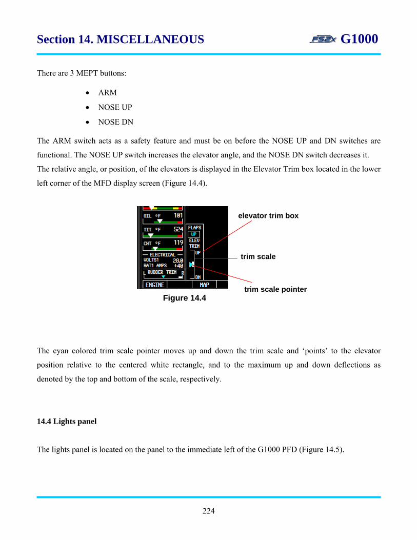
Section 14. MISCELLANEOUS G1000
There are 3 MEPT buttons:
• ARM
• NOSE UP
• NOSE DN
The ARM switch acts as a safety feature and must be on before the NOSE UP and DN switches are
functional. The NOSE UP switch increases the elevator angle, and the NOSE DN switch decreases it.
The relative angle, or position, of the elevators is displayed in the Elevator Trim box located in the lower
left corner of the MFD display screen (Figure 14.4).
The cyan colored trim scale pointer moves up and down the trim scale and ‘points’ to the elevator
position relative to the centered white rectangle, and to the maximum up and down deflections as
denoted by the top and bottom of the scale, respectively.
14.4 Lights panel
The lights panel is located on the panel to the immediate left of the G1000 PFD (Figure 14.5).
elevator trim box
trim scale
trim scale pointer Figure 14.4
224
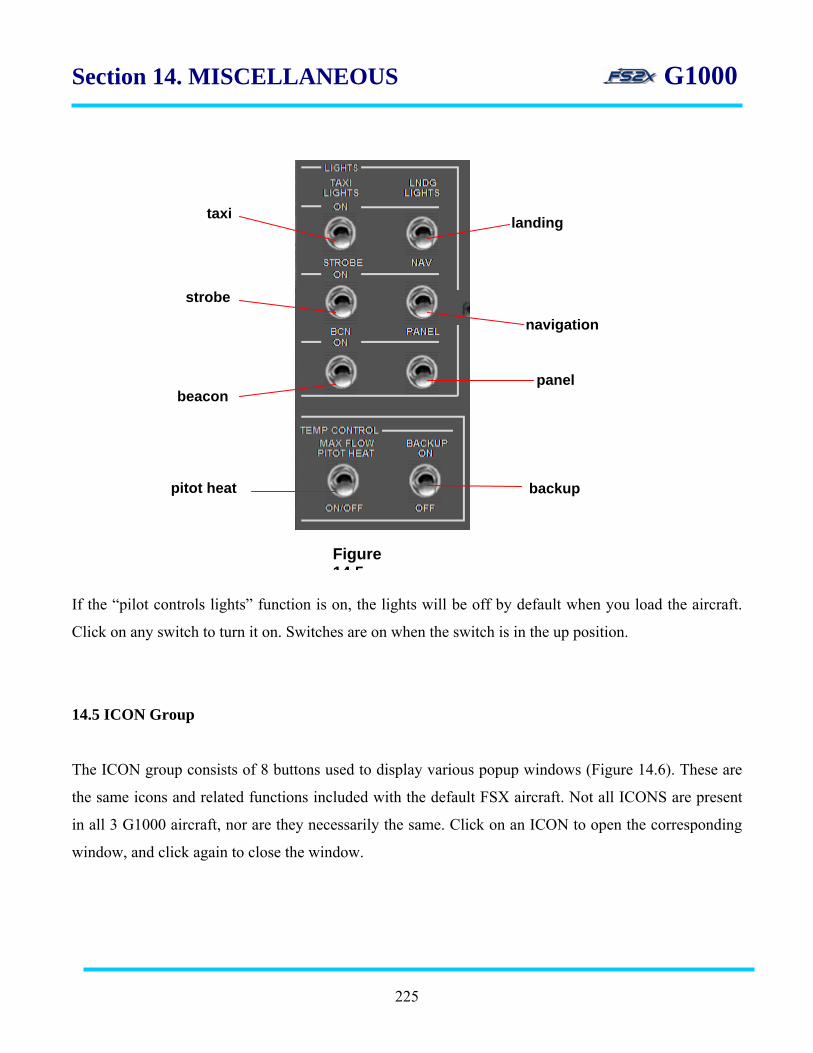
Section 14. MISCELLANEOUS G1000
taxi landing
strobe
navigation
panel beacon
pitot heat backup
Figure 14 5
If the “pilot controls lights” function is on, the lights will be off by default when you load the aircraft.
Click on any switch to turn it on. Switches are on when the switch is in the up position.
14.5 ICON Group
The ICON group consists of 8 buttons used to display various popup windows (Figure 14.6). These are
the same icons and related functions included with the default FSX aircraft. Not all ICONS are present
in all 3 G1000 aircraft, nor are they necessarily the same. Click on an ICON to open the corresponding
window, and click again to close the window.
225
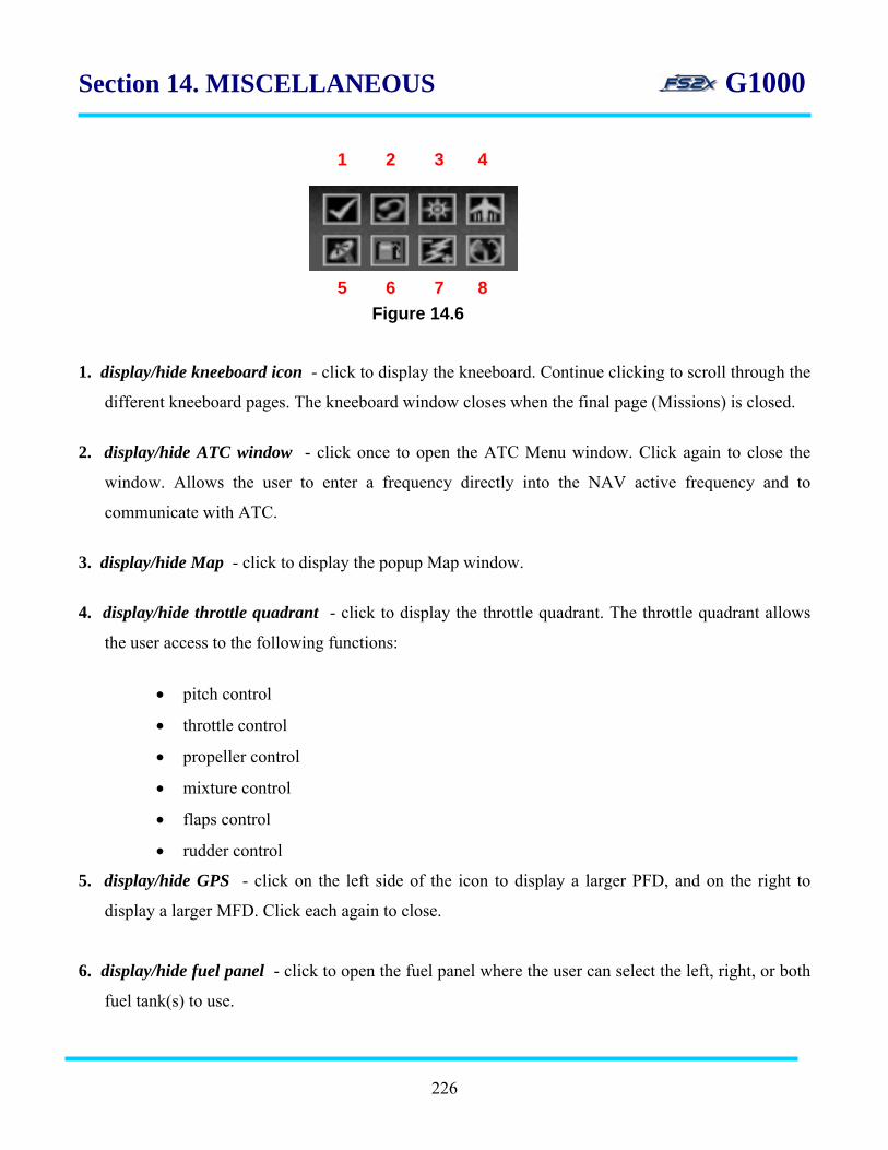
Section 14. MISCELLANEOUS G1000
1 2 3 4
5 6 7 8
Figure 14.6
1. display/hide kneeboard icon - click to display the kneeboard. Continue clicking to scroll through the
different kneeboard pages. The kneeboard window closes when the final page (Missions) is closed.
2. display/hide ATC window - click once to open the ATC Menu window. Click again to close the
window. Allows the user to enter a frequency directly into the NAV active frequency and to
communicate with ATC.
3. display/hide Map - click to display the popup Map window.
4. display/hide throttle quadrant - click to display the throttle quadrant. The throttle quadrant allows
the user access to the following functions:
• pitch control
• throttle control
• propeller control
• mixture control
• flaps control
• rudder control
5. display/hide GPS - click on the left side of the icon to display a larger PFD, and on the right to
display a larger MFD. Click each again to close.
6. display/hide fuel panel - click to open the fuel panel where the user can select the left, right, or both
fuel tank(s) to use.
226

Section 14. MISCELLANEOUS G1000
7. display/hide electrical panel – click to open the electrical panel, click again to close. The electrical
panel has switches for the following functions:
• battery on/off
• reset generator
• fuel boost on/normal/off
• ignition on/normal
• starter start/off
• avionics on/off
8. display/hide engine panel - click to display the engine panel, click again to close the window. The
engine panel displays the following engine parameter gauges:
• inter turbine temperature (ITT)
• % propeller RPM
• fuel flow
• oil pressure and temperature
• left fuel tank quantity
• right tank fuel quantity
227

END
Blank Page
228