gd500‐2 bead detection system -...
TRANSCRIPT

GD500‐2 Bead Detection System
Customer Product ManualPart 1121907_02
Issued 05/14
NORDSON CORPORATION DULUTH, GEORGIA USAwww.nordson.com
This document contains important safety informationBe sure to read and follow all safety information in thisdocument and any other related documentation.

Part 1121907_02 � 05/2014 Nordson CorporationAll rights reserved
Nordson Corporation welcomes requests for information, comments, and inquiries about its products. General informationabout Nordson can be found on the Internet using the following address: http://www.nordson.com.
Address all correspondence to:
Nordson CorporationAttn: Customer Service11475 Lakefield Drive
Duluth, GA 30097
Notice
This is a Nordson Corporation publication which is protected by copyright. Original copyright date 2013.No�part�of�this�document may be photocopied, reproduced, or translated to another language without the prior written
consent of Nordson�Corporation. The�information�contained in this publication is subject to change without notice.
Trademarks
AccuJet, AeroCharge, Apogee, AquaGuard, Asymtek, Automove, Baitgun, Blue Box, Bowtie, Build‐A‐Part, CanWorks, Century, CF, CleanSleeve,CleanSpray, ColorMax, Color‐on‐Demand, Control�Coat, Coolwave, Cross‐Cut, cScan+, Dage, Dispensejet, DispenseMate, DuraBlue, DuraDrum, Durafiber,
DuraPail, Dura‐Screen, Durasystem, Easy�Coat, Easymove Plus, Ecodry, Econo‐Coat, e.DOT, EFD, Emerald, Encore, ESP, e stylized, ETI‐stylized,Excel 2000, Fibrijet, Fillmaster, FlexiCoat, Flex‐O‐Coat, Flow Sentry, Fluidmove, FoamMelt, FoamMix, Fulfill, GreenUV, HDLV, Heli‐flow, Horizon, Hot Shot,
iControl, iDry, iFlow, Isocoil, Isocore, Iso‐Flo, iTRAX, Kinetix, KISS, Lean�Cell, Little�Squirt, LogiComm, Magnastatic, March, Maverick, MEG, Meltex,Microcoat, Micromark, Micromedics, Micro‐Meter, MicroSet, Millennium, MiniBlue, Mini Squirt, Mountaingate, NexJet, No-Drip, Nordson, Optimum,
Package of Values, Paragon, Pattern View, PermaFlo, PICO, PicoDot, Porous�Coat, PowderGrid, Powderware, Precisecoat, Printplus, Prism, ProBlue,Prodigy, Pro‐Flo, Program‐A‐Bead, Program‐A‐Shot, Program‐A‐Stream, Program‐A‐Swirl, ProLink, Pro‐Meter, Pro‐Stream, RBX, Rhino, Saturn,
Saturn with rings, Scoreguard, Sealant Equipment & Engineering, Inc, SEE and design, See‐Flo, Seal Sentry, Select�Charge, Select�Coat, Select Cure,Servo‐Flo, Shot‐A‐Matic, Signature, Slautterback, Smart‐Coat, Solder Plus, Spectrum, Speed‐Coat, SureBead, Sure Coat, Sure‐Max, Sure Wrap,
Tracking�Plus, TRAK, Trends, Tribomatic, TrueBlue, TrueCoat, Tubesetter, Ultra, UpTime, u‐TAH, Value Plastics, Vantage, VersaBlue, Versa‐Coat,VersaDrum, VersaPail, Versa‐Screen, Versa‐Spray,VP Quick Fit, Watermark, When you expect more., and X-Plane
are registered trademarks of Nordson Corporation.
Accubar, Active Nozzle, Advanced Plasma Systems, AeroDeck, AeroWash, Allegro, AltaBlue, AltaSlot, Alta Spray, Artiste, ATS, Auto‐Flo, AutoScan, Axiom, Best Choice, Blue Series, Bravura, CanPro, Champion, Check Mate, ClassicBlue, Classic IX, Clean�Coat, Cobalt, Controlled Fiberization, Control�Weave,
ContourCoat, CPX, cSelect, Cyclo‐Kinetic, DispensLink, Dry Cure, DuraBraid, DuraCoat, DuraPUR, Easy Clean, EasyOn, EasyPW, Eclipse, e.dot+,E‐Nordson, Equalizer, EquiBead, FillEasy, Fill�Sentry, Flow Coat, Fluxplus, Freedom, Get Green With Blue, G‐Net, Genius, G‐Site, IntelliJet, iON, Iso‐Flex,iTrend, Lacquer Cure, Maxima, Mesa, MicroFin, MicroMax, Mikros, MiniEdge, Minimeter, Multifill, MultiScan, Myritex, Nano, OmniScan, OptiMix, OptiStroke,Optix, Partnership+Plus, PatternJet, PatternPro, PCI, PharmaLok, Pinnacle, Plasmod, Powder�Pilot, Powder Port, Powercure, Process Sentry, Pulse Spray,
PURBlue, PURJet, Ready Coat, RediCoat, RollVIA, Quantum, Royal Blue, Select�Series, Sensomatic, Shaftshield, SheetAire, Smart, Smartfil, SolidBlue,Spectral, SpeedKing, Spray Works, StediFlo, StediTherm, Summit, SureFoam, Sure�Mix, SureSeal, Swirl�Coat, TAH, ThruWave, Trade�Plus, Trilogy,
Ultra FoamMix, UltraMax, Ultrasaver, Ultrasmart, Universal, ValueMate, Versa, Vista, Web Cure, YESTECH, and 2�Rings (Design) are�trademarks of Nordson�Corporation.
Designations and trademarks stated in this document may be brands that, when used by third parties for their own purposes, could lead to violation of the owners' rights.

Table of Contents i
Part 1121907_02� 05/2014 Nordson Corporation
Table of Contents
Safety 1. . . . . . . . . . . . . . . . . . . . . . . . . . . . . . . . . . . . . . . . . . . . . . . . . . . . . .Qualified Personnel 1. . . . . . . . . . . . . . . . . . . . . . . . . . . . . . . . . . . . . . . . . . .Intended Use 1. . . . . . . . . . . . . . . . . . . . . . . . . . . . . . . . . . . . . . . . . . . . . . . .Safety Alert Symbols 2. . . . . . . . . . . . . . . . . . . . . . . . . . . . . . . . . . . . . . . . . .Regulations and Approvals 2. . . . . . . . . . . . . . . . . . . . . . . . . . . . . . . . . . . .Personal Safety 2. . . . . . . . . . . . . . . . . . . . . . . . . . . . . . . . . . . . . . . . . . . . . .Fire Safety 3. . . . . . . . . . . . . . . . . . . . . . . . . . . . . . . . . . . . . . . . . . . . . . . . . . .Action in the Event of a Malfunction 3. . . . . . . . . . . . . . . . . . . . . . . . . . . . .Equipment Disposal 3. . . . . . . . . . . . . . . . . . . . . . . . . . . . . . . . . . . . . . . . . .
System Overview 4. . . . . . . . . . . . . . . . . . . . . . . . . . . . . . . . . . . . . . . . . . .System Components 6. . . . . . . . . . . . . . . . . . . . . . . . . . . . . . . . . . . . . . . . . .
GD500‐2 Controller 6. . . . . . . . . . . . . . . . . . . . . . . . . . . . . . . . . . . . . . . . .GD500 Sensor for Corrugated Machines 7. . . . . . . . . . . . . . . . . . . . . . .Trigger 7. . . . . . . . . . . . . . . . . . . . . . . . . . . . . . . . . . . . . . . . . . . . . . . . . . .Encoder 7. . . . . . . . . . . . . . . . . . . . . . . . . . . . . . . . . . . . . . . . . . . . . . . . . .
Installation 8. . . . . . . . . . . . . . . . . . . . . . . . . . . . . . . . . . . . . . . . . . . . . . . . .Required Equipment 8. . . . . . . . . . . . . . . . . . . . . . . . . . . . . . . . . . . . . . . . . .Unpacking the GD500 Sensor 8. . . . . . . . . . . . . . . . . . . . . . . . . . . . . . . . . .Dimensions 9. . . . . . . . . . . . . . . . . . . . . . . . . . . . . . . . . . . . . . . . . . . . . . . . . .
GD500‐2 Controller 9. . . . . . . . . . . . . . . . . . . . . . . . . . . . . . . . . . . . . . . . .GD500 Sensor for Corrugated Machines 10. . . . . . . . . . . . . . . . . . . . .
Mounting Guidelines 11. . . . . . . . . . . . . . . . . . . . . . . . . . . . . . . . . . . . . . . . . .Mounting the GD500‐2 Controller 11. . . . . . . . . . . . . . . . . . . . . . . . . . . . . . .Mounting the GD500 Sensor 11. . . . . . . . . . . . . . . . . . . . . . . . . . . . . . . . . . .
Corrugated System 12. . . . . . . . . . . . . . . . . . . . . . . . . . . . . . . . . . . . . . . . .Sensors Mounted on a Reference Bracket 14. . . . . . . . . . . . . . . . . . . .
Connecting the Systems 16. . . . . . . . . . . . . . . . . . . . . . . . . . . . . . . . . . . . . .Starting the System 17. . . . . . . . . . . . . . . . . . . . . . . . . . . . . . . . . . . . . . . . . .
GD500‐2 Controller Operator Panel 18. . . . . . . . . . . . . . . . . . . . . . . . . .
Operational Overview 20. . . . . . . . . . . . . . . . . . . . . . . . . . . . . . . . . . . . . . .Operational Overview of the Reference Sensor 23. . . . . . . . . . . . . . . . . . .
Set Sensitivity Threshold 23. . . . . . . . . . . . . . . . . . . . . . . . . . . . . . . . . . .Set Delay Distance Between Sensor 1 and Sensor 2 24. . . . . . . . . . .Set Compensation Between Sensor 1 and Sensor 2 25. . . . . . . . . . . .

Table of Contentsii
Part 1121907_02 � 05/2014 Nordson Corporation
Setup 26. . . . . . . . . . . . . . . . . . . . . . . . . . . . . . . . . . . . . . . . . . . . . . . . . . . . . .When to Adjust Service Settings 26. . . . . . . . . . . . . . . . . . . . . . . . . . . . . . . .Setting Up the Service Menu 26. . . . . . . . . . . . . . . . . . . . . . . . . . . . . . . . . .
Run Mode 26. . . . . . . . . . . . . . . . . . . . . . . . . . . . . . . . . . . . . . . . . . . . . . . . .Sensor Trigger Offset (STO) 27. . . . . . . . . . . . . . . . . . . . . . . . . . . . . . . . .Calibration Samples 28. . . . . . . . . . . . . . . . . . . . . . . . . . . . . . . . . . . . . . . .Minimum Tolerance 28. . . . . . . . . . . . . . . . . . . . . . . . . . . . . . . . . . . . . . . .
Example 1 29. . . . . . . . . . . . . . . . . . . . . . . . . . . . . . . . . . . . . . . . . . . . . .Example 2 30. . . . . . . . . . . . . . . . . . . . . . . . . . . . . . . . . . . . . . . . . . . . . .
Maximum Tolerance 31. . . . . . . . . . . . . . . . . . . . . . . . . . . . . . . . . . . . . . . .Sensitivity Threshold 33. . . . . . . . . . . . . . . . . . . . . . . . . . . . . . . . . . . . . . .Encoder Ratio 33. . . . . . . . . . . . . . . . . . . . . . . . . . . . . . . . . . . . . . . . . . . . .Language 34. . . . . . . . . . . . . . . . . . . . . . . . . . . . . . . . . . . . . . . . . . . . . . . . .Software Version 34. . . . . . . . . . . . . . . . . . . . . . . . . . . . . . . . . . . . . . . . . . .Return to Run Mode 34. . . . . . . . . . . . . . . . . . . . . . . . . . . . . . . . . . . . . . . .Dynamic Calibration 35. . . . . . . . . . . . . . . . . . . . . . . . . . . . . . . . . . . . . . .
Calibrate from the GD500‐2 Controller 35. . . . . . . . . . . . . . . . . . . . . .Calibrate from the LogiComm Touch‐screen 36. . . . . . . . . . . . . . . . .
Learn Pattern Setup 37. . . . . . . . . . . . . . . . . . . . . . . . . . . . . . . . . . . . . . . . . .Glue Sensor Input Set‐up 37. . . . . . . . . . . . . . . . . . . . . . . . . . . . . . . . . . .
Template Verification for Glue Sensor Input 37. . . . . . . . . . . . . . . . . .Excess Sensor Input Set‐up 38. . . . . . . . . . . . . . . . . . . . . . . . . . . . . . . . .
Maximum Setting for Excess Sensor Input 38. . . . . . . . . . . . . . . . . . .
Maintenance 40. . . . . . . . . . . . . . . . . . . . . . . . . . . . . . . . . . . . . . . . . . . . . . . .
Parts List 41. . . . . . . . . . . . . . . . . . . . . . . . . . . . . . . . . . . . . . . . . . . . . . . . . . .GD500‐2 Parts for Corrugated Machines 41. . . . . . . . . . . . . . . . . . . . . . . .Optional Reference Detection 41. . . . . . . . . . . . . . . . . . . . . . . . . . . . . . . . . .
Appendix A A‐1. . . . . . . . . . . . . . . . . . . . . . . . . . . . . . . . . . . . . . . . . . . . . . . . .Adhesive Image Software A‐1. . . . . . . . . . . . . . . . . . . . . . . . . . . . . . . . . . . .System Requirements A‐1. . . . . . . . . . . . . . . . . . . . . . . . . . . . . . . . . . . . . . . . .Software Download Location A‐1. . . . . . . . . . . . . . . . . . . . . . . . . . . . . . . . . . .Before Downloading the Software A‐1. . . . . . . . . . . . . . . . . . . . . . . . . . . . . . .Download the Software A‐2. . . . . . . . . . . . . . . . . . . . . . . . . . . . . . . . . . . . . . . .Software Setup A‐2. . . . . . . . . . . . . . . . . . . . . . . . . . . . . . . . . . . . . . . . . . . . . .
Sensor 1 Compensation Setting A‐4. . . . . . . . . . . . . . . . . . . . . . . . . . . . . .Troubleshooting Signal Alignment A‐6. . . . . . . . . . . . . . . . . . . . . . . . . . . . . . .

GD500‐2 Bead Detection System 1
Part 1121907_02� 05/2014 Nordson Corporation
GD500‐2 Bead Detection System
Safety Read this section before using the equipment. This section containsrecommendations and practices applicable to the safe installation, operation,and maintenance (hereafter referred to as “use”) of the product described inthis document (hereafter referred to as “equipment”). Additional safetyinformation, in the form of task‐specific safety alert messages, appears asappropriate throughout this document.
WARNING! Failure to follow the safety messages, recommendations, andhazard avoidance procedures provided in this document can result inpersonal injury, including death, or damage to equipment or property.
Qualified Personnel
Equipment owners are responsible for making sure that Nordson equipmentis installed, operated, and serviced by qualified personnel. Qualifiedpersonnel are those employees or contractors who are trained to safely�perform their assigned tasks. They are familiar with all relevant safety rulesand regulations and are physically capable of performing their assignedtasks.
Intended Use
Use of Nordson equipment in ways other than those described in thedocumentation supplied with the equipment may result in injury to persons ordamage to property.
Some examples of unintended use of equipment include:
� using incompatible materials
� making unauthorized modifications
� removing or bypassing safety guards or interlocks
� using incompatible or damaged parts
� using unapproved auxiliary equipment
� operating equipment in excess of maximum ratings

GD500‐2 Bead Detection System2
Part 1121907_02 � 05/2014 Nordson Corporation
Safety Alert Symbols
The following safety alert symbol and signal words are used throughout thisdocument to alert the reader to personal safety hazards or to identifyconditions that may result in damage to equipment or property. Comply withall safety information that follows the signal word.
WARNING! Indicates a potentially hazardous situation that, if not avoided,can result in serious personal injury, including death.
CAUTION: Indicates a potentially hazardous situation that, if not avoided,
can result in minor or moderate personal injury.
CAUTION: (Used without the safety alert symbol) Indicates a potentially
hazardous situation that, if not avoided, can result in damage to equipment or
property.
Regulations and Approvals
Make sure all equipment is rated and approved for the environment in whichit is used. Any approvals obtained for Nordson equipment will be voided ifinstructions for installation, operation, and service are not followed.
All phases of equipment installation must comply with all federal, state, andlocal codes.
Personal Safety
To prevent injury follow these instructions.
� Do not operate or service equipment unless you are qualified.
� Do not operate equipment unless safety guards, doors, or covers are
intact and automatic interlocks are operating properly. Do not bypass ordisarm any safety devices.
� Keep clear of moving equipment. Before adjusting or servicing any
moving equipment, shut off the power supply and wait until the equipmentcomes to a complete stop. Lock out power and secure the equipment toprevent unexpected movement.
� Relieve (bleed off) hydraulic and pneumatic pressure before adjusting or
servicing pressurized systems or components. Disconnect, lock out, andtag switches before servicing electrical equipment.

GD500‐2 Bead Detection System 3
Part 1121907_02� 05/2014 Nordson Corporation
� If you receive even a slight electrical shock, shut down all electrical
equipment immediately. Do not restart the equipment until the problemhas been identified and corrected.
� Obtain and read Material Safety Data Sheets (MSDS) for all materials
used. Follow the manufacturer's instructions for safe handling and use ofmaterials, and use recommended personal protection devices.
� To prevent injury, be aware of less‐obvious dangers in the workplace that
often cannot be completely eliminated, such as hot surfaces, sharpedges, energized electrical circuits, and moving parts that cannot beenclosed or otherwise guarded for practical reasons.
Fire Safety
To avoid a fire or explosion, follow these instructions.
� Shut down all equipment immediately if you notice static sparking or
arcing. Do not restart the equipment until the cause has been identifiedand corrected.
� Do not smoke, weld, grind, or use open flames where flammable
materials are being used or stored.
� Provide adequate ventilation to prevent dangerous concentrations of
volatile materials or vapors. Refer to local codes or your material MSDSfor guidance.
� Do not disconnect live electrical circuits while working with flammable
materials. Shut off power at a disconnect switch first to prevent sparking.
� Know where emergency stop buttons, shut off valves, and fire
extinguishers are located.
� Clean, maintain, test, and repair equipment according to the instructions
in your equipment documentation.
� Use only replacement parts that are designed for use with original
equipment. Contact your Nordson representative for parts informationand advice.
Action in the Event of a Malfunction
If a system or any equipment in a system malfunctions, shut off the systemimmediately and perform the following steps:
� Disconnect and lock out electrical power. Close pneumatic shutoff valves
and relieve pressure.
� Identify the reason for the malfunction and correct it before restarting the
equipment.
Equipment Disposal
Dispose the equipment and materials used in operation and servicingaccording to local codes.

GD500‐2 Bead Detection System4
Part 1121907_02 � 05/2014 Nordson Corporation
System Overview This manual describes the installation, connection, setup, and operation ofthe GD500‐2 controller and GD500 sensor when used with the LogiComm� control system.
The GD500‐2 Bead Detection System includes a sensor configuration that isspecific for corrugated machines.
The GD500 sensor monitors liquid adhesive applications, such asside‐seam, wheel‐pot, or extrusion applications, for too much or too littleadhesive. A keypad and an LCD display on the GD500‐2 controller allowsalarm thresholds to be set in order to prevent weak bonds or squeeze‐out.The sensor has an automatic calibration feature to aid in establishingaccurate maximum and minimum settings. When used with the LogiCommsystem, defective products are tracked through the machine and ejected ormarked for later ejection.
See Figure 1 for a system overview.

GD500‐2 Bead Detection System 5
Part 1121907_02� 05/2014 Nordson Corporation
8
9
Figure 1 System components
1. LogiComm control module
2. Touch‐screen
3. Controller (front and base panelviews)
4. LogiComm cable
5. Trigger
6. Sensor 1
7. Encoder
8. Second Trigger
9. Optional reference Sensor 2

GD500‐2 Bead Detection System6
Part 1121907_02 � 05/2014 Nordson Corporation
System Components
The following components make up the GD500‐2 bead detection system:
� GD500‐2 controller
� GD500 Sensor 1
� Optional second reference Sensor 2
� Trigger
� Encoder
� LogiComm control system (control module and touch‐screen)
GD500‐2 Controller
The GD500‐2 controller is an adhesive detection unit that works inconjunction with the GD500 sensor to monitor the amount of liquid adhesiveon different materials, such as paper, carton, etc. The GD500‐2 controllercontains an operator panel that allows for programming and operation.
Figure 2 GD500‐2 controller showing the connector panel
1. GD500‐2 controller
2. Operator panel
3. Connector panel

GD500‐2 Bead Detection System 7
Part 1121907_02� 05/2014 Nordson Corporation
GD500 Sensor for Corrugated Machines
The GD500 sensor (Sensor 1 or S1) measures the amount of liquid adhesiveon the substrate as it passes between the sensor arms.
This system allows the option of using a second sensor (Sensor 2 or S2) forreference purposes.
Figure 3 GD500 sensor for corrugated machines
1. Power input/signal output connector
2. Sensor measuring points
3. Sensor arms
4. Shock absorber and mounting bolts
Trigger
The trigger signal is transmitted from the photocell to the GD500‐2 systemand then to the trigger input on the LogiComm pattern control bank, forproduct tracking and displaying the measurement on the touch‐screen.
Encoder
The GD500 sensor uses the encoder signal from the Encoder Repeateroutput on the LogiComm master bank. By default the GD500‐2 controller isset for a ratio of 1 pulse/mm, but other ratios can be set through the GD500‐2controller menu.

GD500‐2 Bead Detection System8
Part 1121907_02 � 05/2014 Nordson Corporation
Installation
WARNING! Allow only qualified personnel to perform the following tasks.Follow the safety instructions in this document and all other relateddocumentation.
This section describes the following instructions:
� Mount the GD500 sensor and controller
� Connect the GD500 sensor through the GD500‐2 controller to the
LogiComm control module
NOTE: The sensor is IP56 (NEMA 4) rated.
NOTE: The words glue and adhesive are used interchangeably in thismanual.
Required Equipment
Make sure that the following items are available for installation:
� GD500‐2 controller
� GD500 sensor
� Optional second reference sensor
� Mounting brackets
� GD500‐2 controller and sensor interconnect cable
� LogiComm interface cable
� Trigger and trigger cable
� GD500‐2 controller key
� GD500‐2 manual
Unpacking the GD500 Sensor 1. Carefully unpack the contents of the box. Exercise care to prevent
equipment damage during unpacking.
2. Inspect for any damage that may have occurred during shipping. Reportany damage to your Nordson representative.

GD500‐2 Bead Detection System 9
Part 1121907_02� 05/2014 Nordson Corporation
Dimensions
GD500‐2 Controller
The GD500‐2 controller dimensions are as follows:
197 mm(7.75 in.)
203 mm(7.99 in.)
20
8 m
m(8
.18
in.)
19
7 m
m(7
.75
in.)
80 mm(3.14 in.)
90 mm(3.54 in.)
1
Figure 4 GD500‐2 controller dimensions
1. Magnet location

GD500‐2 Bead Detection System10
Part 1121907_02 � 05/2014 Nordson Corporation
GD500 Sensor for Corrugated Machines
The GD500 sensor dimensions for corrugated machines are as follows:
Figure 5 Corrugated sensor dimensions

GD500‐2 Bead Detection System 11
Part 1121907_02� 05/2014 Nordson Corporation
Mounting Guidelines
Observe the following guidelines when installing the GD500 sensor:
� Make sure that the mounting location provides sufficient clearance for
easy access to the connectors and the associated cables.
� Select a location to provide access to the operator panel for
programming.
� The sensor is designed to operate between 0 and 50 �C
(32 and 122 �F).
� The sensor arms must be kept free of dirt, dust, and adhesive.
Mounting the GD500‐2 Controller
Install the controller using the magnets that are located on the back of thecontroller.
Mounting the GD500 Sensor
The GD500 sensor must be mounted on a bracket assembly for thecorrugated system. Proper mounting of the adhesive sensors is important toobtain optimum operation of the liquid adhesive detection system.
See Figure 6 for the components required to mount the sensor and trigger ona bracket assembly for corrugated systems.

GD500‐2 Bead Detection System12
Part 1121907_02 � 05/2014 Nordson Corporation
Corrugated System
The following figure shows the sensor mounted on a bracket for thecorrugated system.
Figure 6 Sensor and trigger mounted on a bracket assembly for corrugated machines
1. Corrugated market bracketassembly
2. Sensor
3. Sensor arms
4. Protection bars
5. Lower guide bar
6. Trigger
GD500‐2 Bead Detection System 13
Part 1121907_02� 05/2014 Nordson Corporation
1. Mount the sensor assembly (bracket, sensor, and trigger) on themachine.
2. Make sure that the sensor arms are protected by the protection bars ofthe bracket to avoid damage to the sensor.
3. Align the opening in the bracket so the product passes freely through theopening. The lower guide bar must be at the same height as the belt ofthe machine.
4. Align adhesive pattern with the optimum sensing point on the sensor,marked by middle dot on the short sensor arm.
NOTE: For optimum results, the application must be aligned (centered)with the middle dot on the sensor.
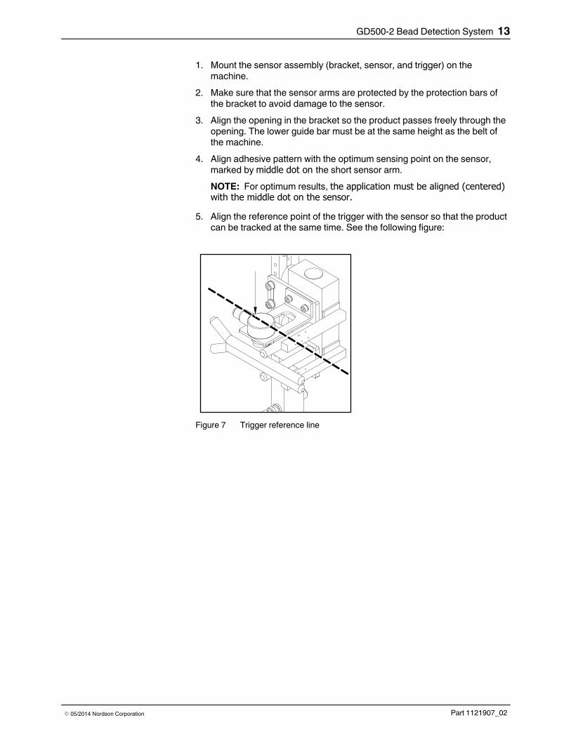
5. Align the reference point of the trigger with the sensor so that the productcan be tracked at the same time. See the following figure:
Figure 7 Trigger reference line

GD500‐2 Bead Detection System14
Part 1121907_02 � 05/2014 Nordson Corporation
Sensors Mounted on a Reference Bracket
1
2
3
4
4
6
7
5
Figure 8 Mounting Sensor 1 and Sensor 2 on a reference bracket
1. Sensor 1
2. Middle of application referenceline
3. Trigger position B
4. Dot in the middle of sensor
5. Trigger position A
6. Product trigger
7. Sensor 2

GD500‐2 Bead Detection System 15
Part 1121907_02� 05/2014 Nordson Corporation
1. Mount the sensor assembly (bracket, sensors, and triggers) on themachine.
2. For product detection, mount trigger at position A and B (see items 3 and5 in Figure 8). In most cases the trigger is mounted only on position B.
3. Make sure that the sensor arms are protected by the protection bars ofthe bracket to avoid damage to the sensor.
4. Align the opening in the bracket so that the product passes freely throughthe opening. The lower guide bar must be at the same height as the beltof the machine.
5. Align adhesive pattern with the optimum sensing point on the Sensor 1,which is marked by the middle dot on the short sensor arm (see item 4 inFigure 8).
6. Align Sensor 2 to Sensor 1 so that the product width can be tracked atthe same time. Make sure both sensors are centered along the middle ofthe application (see item 2 in Figure 8).
NOTE: For optimum results, Trigger B must be aligned (centered) withthe middle of the application (see item 2 in Figure 8).

GD500‐2 Bead Detection System16
Part 1121907_02 � 05/2014 Nordson Corporation
Connecting the Systems
The following figure shows the cables that connect GD500‐2 controllersensor to the LogiComm control module.
6
3
3
4
4a 4b
51 2
2
Figure 9 Cable connections

GD500‐2 Bead Detection System 17
Part 1121907_02� 05/2014 Nordson Corporation
Table 1 Controller cables and the connecting devices
Connector Name Connecting Device
1. S1 (Sensor 1) Connects from the GD500‐2 controller to the GD500 sensor.
The following connectors (items 2, 3, and 4) are bundled together as a single harness:
2. Tout (Trigger out) Connects from the GD500‐2 controller to any Trigger input connector on thecontrol module. The harness is connected to Trigger B1 on the control module, asshown in Figure 9.
3. Enc (Encoder) Connects from the GD500‐2 controller to the Encoder Repeater connector on theMaster I/O panel of the control module.
4. LC (LogiComm) Connects from the GD500‐2 controller to two Sensor input connectors on theVerification panel of the control module.
4a. GlueConnects to the Glue sensor input. The harness is connected to Sensor B1, asshown in Figure 9.
4b. Excess Connects to the Excess sensor input. The harness is connected to Sensor B2, asshown in Figure 9.
5. Port Nordson use only.
6. S2 (Sensor 2)
Optional referencesensor connector.
Connects from the GD500‐2 controller to the GD500 (reference) sensor tomonitor the substrate variance.
Starting the System
Do the following to start the system:
� Make sure that the GD500‐2 controller and sensor are connected to the
LogiComm control module.
� Make sure that the LogiComm control module's power cable is
connected to a grounded outlet.
� Turn on the LogiComm control module.
NOTE: The GD500‐2 system receives power from the 24 VDC output of theLogiComm sensor input.

GD500‐2 Bead Detection System18
Part 1121907_02 � 05/2014 Nordson Corporation
GD500‐2 Controller Operator Panel Use the operator panel to program the system for operation.
Refer to Table 2 for an explanation of the operator panel buttons and LEDsfunctionality.
Figure 10 GD500‐2 controller
1. Operator panel 2. Operator panel buttons

GD500‐2 Bead Detection System 19
Part 1121907_02� 05/2014 Nordson Corporation
Table 2 Operator panel buttons and LEDs functionality
Button Name Function
Dynamiccalibration andRun Menubutton
Press this button for 2 seconds for the system to activate DynamicCalibration mode.
LED: Turns green to indicate that the system is in run mode, andturns yellow during dynamic calibration.
Decrease valuebutton
Press this button to decrease the value of a parameter.
LED: Not used.
Increase valuebutton
Press this button to increase the value of a parameter.
LED: Turns green to indicate a trigger signal.
Service Menubutton
1 Press this button for 2 seconds to activate the Service menu.
2 Press this button to scroll through the menu screens.
LED: Turns yellow to indicate that the system is ready for setup.

GD500‐2 Bead Detection System20
Part 1121907_02 � 05/2014 Nordson Corporation
Operational Overview The GD500‐2 system monitors the amount of liquid adhesive on a product bymeasuring the dielectric coefficient of the material passing between thesensor arms. The dielectric measurement is directly related to the amount ofadhesive on the carton or other substrate. The GD500‐2 controller learns thecorrect amount of adhesive during an automated dynamic calibrationprocess, see item 6 in Figure 11. The alarm levels are then set to monitor theupper (MAX) and lower (MIN) deviations from the calibration level.
2 3
4
1
5
6
MAX
MIN
7
On
Off
Off
Off
On On
6
a b
Figure 11 Calibration and tolerance settings
1. Machine direction
2. Substrate
3. Glue bead
4. Sensor
5. Sensor signalsa: Glue inputb: Excess input
6. Calibration
7. Substrate signal

GD500‐2 Bead Detection System 21
Part 1121907_02� 05/2014 Nordson Corporation
There are two outputs from the GD500‐2 that connect to the LogiCommsensor inputs:
� Glue
The Glue sensor input provides a signal to LogiComm when glue isdetected.
� Excess
The Excess sensor input provides a signal to LogiComm when toomuch glue is detected (above the MAX limit). Also see item 5 inFigure 11 for the status of the two inputs at different signal levels.
06 Feb 2012 06:45:2*
Select
Select
Select
Select
Glue ON
Verification ON
Machine Stop Disabled
Reject OFFPower DownGD500 Glue
Sensor Product Count128,279
Glue 1B2Product Count
98,339
Line Speed 10.0 m/min
Home
Help
Clear Pattern Error
Glue 1B1Product Count
128,279
GD500 GLUESensor Product Count
128,279
Monitor Sensors
Message Log
GD 500 GLUE
GD 500 EXCESS
Inspect 1A3
Inspect 1A4
Product: 166,809
Product: 166,809
Product: 166,809
Product: 166,809
Figure 12 Glue and Excess output settings as it appears on the Monitor screen of the touch‐screen
The sensor is also sensitive enough to read the change in dielectricmeasurement due to the carton passing between the sensor arms, see item 7 in Figure 11.

GD500‐2 Bead Detection System22
Part 1121907_02 � 05/2014 Nordson Corporation
Operational Overview (contd)
The sensitivity is adjusted to eliminate false signals from the carton, seeFigure 13.
If the sensitivity threshold level is set too high, the glue sensor will not sensethe board or the glue and the outputs will not change. If the sensitivitythreshold level is set too low, the sensor will be too sensitive and glueoutputs will change as soon as the edge of the board enters between thesensor arms. The correct sensitivity setting is shown in the following figure:
2 3
4
1
5
6
a
c
b
a
c
b
Figure 13 Sensitivity threshold setting
1. Machine direction
2. Substrate
3. Glue bead
4. GD‐500 sensor
5. Sensor signala: Sensitivity level highb: Sensitivity level correctc: Sensitivity level low
6. Glue output signala: Sensitivity level highb: Sensitivity level correctc: Sensitivity level low
GD500‐2 Bead Detection System 23
Part 1121907_02� 05/2014 Nordson Corporation
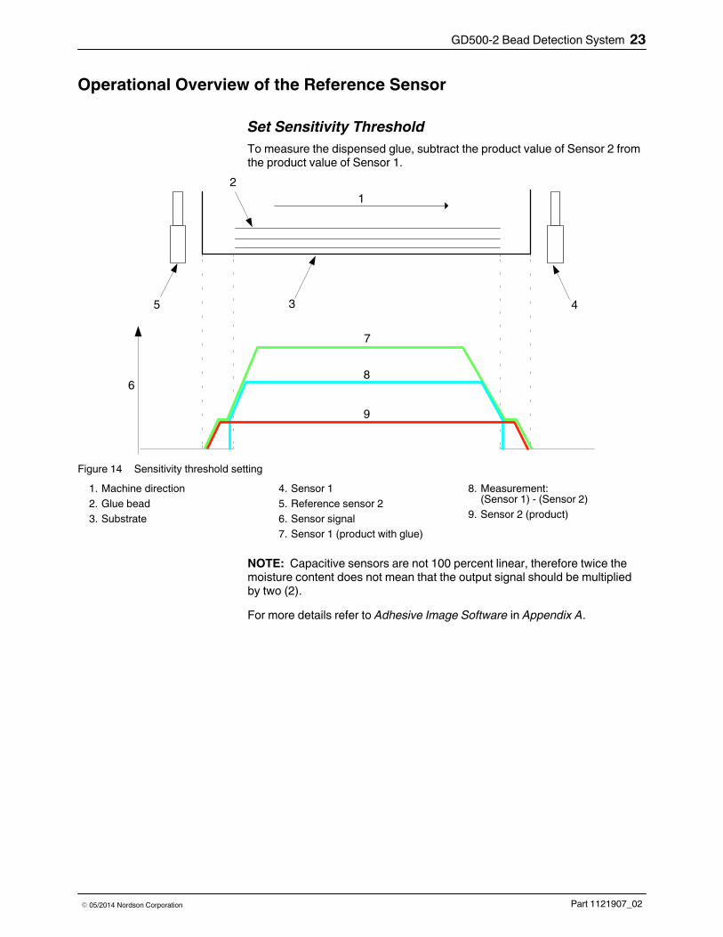
Operational Overview of the Reference Sensor
Set Sensitivity Threshold
To measure the dispensed glue, subtract the product value of Sensor 2 fromthe product value of Sensor 1.
4
1
2
6
7
35
8
9
Figure 14 Sensitivity threshold setting
1. Machine direction
2. Glue bead
3. Substrate
4. Sensor 1
5. Reference sensor 2
6. Sensor signal
7. Sensor 1 (product with glue)
8. Measurement:(Sensor 1) - (Sensor 2)
9. Sensor 2 (product)
NOTE: Capacitive sensors are not 100 percent linear, therefore twice themoisture content does not mean that the output signal should be multipliedby two (2).
For more details refer to Adhesive Image Software in Appendix A.

GD500‐2 Bead Detection System24
Part 1121907_02 � 05/2014 Nordson Corporation
Set Delay Distance Between Sensor 1 and Sensor 2
Refer to Figure 15 to determine the delay distance between Sensor 1 andSensor 2. With this distance information, the system subtracts the referencevalue measured by sensor 2 from the value measured by sensor 1 at thesame position on the product.
4
6
5
12
3
Figure 15 Distance between Sensor 2 and Sensor 1 (delay settings)
1. Machine direction
2. Glue bead
3. Substrate
4. Reference sensor 2
5. Sensor 1
6. Delay distance
Press or to enter the Delay distance (in millimeter).

GD500‐2 Bead Detection System 25
Part 1121907_02� 05/2014 Nordson Corporation
Set Compensation Between Sensor 1 and Sensor 2
This setting is used to calibrate the amplitude of the output signal of Sensor 1and Sensor 2. Both sensors must respond exactly the same for the samemoisture content.
During installation determine the difference between Sensor 1 and Sensor 2by passing a carton without glue. Set the Sensor 1 compensation setting togenerate the same value.
For more details refer to Adhesive Image Software in Appendix A.
11
7
4
6
5
10
89
12
3
Figure 16 Compensation settings
1. Machine direction
2. Glue bead
3. Substrate
4. Sensor 1
5. Reference sensor 2
6. Sensor signal
7. Sensor 1
8. Measurement: (Sensor 1) - (Sensor 2)
9. Sensor 2
10. Sensor 1 compensation >1
11. Sensor 1 compensation <1
NOTE: The default compensation setting for Sensor 1 is one (1), whichmeans the contribution of Sensor 1 and Sensor 2 is equal. If required in theapplication, the contribution of Sensor 1 on the measurement can beamplified (>1) or reduced (<1) by changing the value.
1. Press to scroll to the Compensation Sensor 1 setting menu.
2. Press or to enter the optimum Sensor 1 compensation setting.Refer to Figure 16 to determine the optimum Sensor 1 compensation setting.

NordsonGD500Run mode
GD500‐2 Bead Detection System26
Part 1121907_02 � 05/2014 Nordson Corporation
Setup
When to Adjust Service Settings
Under normal operation the Service menu settings do not change. However,the sensitivity may need to be adjusted for different board materials, whenthere has been a product changeover. The maximum and minimum settingscan be adjusted for different products.
NOTE: The words glue and adhesive are used interchangeably in thissection.
Setting Up the Service Menu
Run Mode
Once the system is installed and the LogiComm control module is poweredup, the GD500‐2 system turns on and opens Run mode. The system is nowready to be set up.
NOTE: The Run button LED turns green to indicate that the system is in Runmode.
Press for two seconds to open the Service menu and begin the setupprocedures.
NOTE: The Service menu button LED turns yellow.

Service menu:STO<34> mm
GD500‐2 Bead Detection System 27
Part 1121907_02� 05/2014 Nordson Corporation
Sensor Trigger Offset (STO)
1. Press to scroll to the STO setting menu.
2. Press or to enter the STO distance in millimeters.
Refer to the following figure to determine the STO distance.
23 4
1
6
57
8
Figure 17 STO settings
1. Machine direction
2. Substrate
3. Glue bead
4. Trigger
5. GD‐500 sensor
6. STO
7. Sensor signal
8. Trigger signal
NOTE: The default STO value is 30 mm. For corrugated brackets the STOdistance is approximately 34 mm (1.33 in.).
Service menu:Samples<5> stk
Service menu: - Tolerance <20> %
GD500‐2 Bead Detection System28
Part 1121907_02 � 05/2014 Nordson Corporation
Calibration Samples
1. Press to scroll to the Calibration Samples menu.
This setting determines the number of pieces the sensor measuresduring calibration. Refer to Figure 11 for calibration and tolerancesettings. The sensor calculates the average measurement of theprogrammed number of samples.
2. Press or to select between 1 to 10 pieces. The typical setting isfive (5).
Minimum Tolerance
1. Press to scroll to the Minimum Tolerance menu.
Minimum tolerance is the amount below the calibrated signal level wherethe glue output signal does not indicate the presence of glue.
2. Press or to select minimum tolerance. The default setting is15% and the range is 0-100%.
See Figures 18 and 20 for examples of minimum tolerance defect settings.

GD500‐2 Bead Detection System 29
Part 1121907_02� 05/2014 Nordson Corporation
Example 1
Figure 18 shows an example of a minimum tolerance defect and Figure 19 isthe LogiComm touch‐screen with the corresponding settings.
1
2
5
4
3
Figure 18 Minimum tolerance settings showing low glue amount or not enough glue
1. Not enough glue or low glueamount
2. Sensor signal
3. Maximum setting
4. Calibration
5. Minimum setting
Trigger 1
Sensor Menu - GD500 GLUE
Learn Pattern
Properties
Clear Pattern Error
Active Manual
Help
Home
No Beads
Bead Tolerance
All Beads
Start
(mm)
7.00 7.00
Stop
(mm)
Inspection Parameters
Product: 416,996
Product: Length 64.00 mm
Autoscale
10 mm 20mm 30 mm 40 mm 50 mm 60 mm 70
Alarm - GD500 GLUE - Product failed pattern verification.
Figure 19 Bead error settings on the touch‐screen

GD500‐2 Bead Detection System30
Part 1121907_02 � 05/2014 Nordson Corporation
Example 2
Figure 20 shows another example of a minimum tolerance defect and Figure 21 is the LogiComm touch‐screen with the corresponding settings.
2
5
4
3
1
Figure 20 Minimum tolerance settings showing broken glue bead
1. Broken glue bead
2. Sensor signal
3. Maximum setting
4. Calibration
5. Minimum setting
Trigger 1
Sensor Menu - GD500 GLUE
Learn Pattern
Properties
Clear Pattern Error
Active Manual
Help
Home
Bead 9972172 ended early by 32.00 mm
Bead Tolerance
All Beads
Start
(mm)
7.00 7.00
Stop
(mm)
Inspection Parameters
Product: 416,996
Product: Length 64.00 mm
Autoscale
10 mm 20mm 30 mm 40 mm 50 mm 60 mm 70
Alarm - GD500 GLUE - Product failed pattern verification.
Bead Start Duration
(mm) (mm)
1 10.26 9.26
2 30.25 24.25
Figure 21 Bead error settings on the touch‐screen

Service menu: + Tolerance <21> %
GD500‐2 Bead Detection System 31
Part 1121907_02� 05/2014 Nordson Corporation
Maximum Tolerance
1. Press to scroll to the Maximum Tolerance menu.
Maximum Tolerance is the amount above the calibrated signal levelwhere the max output signal will indicate excess glue.
2. Press or to select maximum tolerance. The default setting is15% and the range is 0-100%.
Figure 22 shows an example of a maximum tolerance defect caused byexcess glue and Figure 23 is the LogiComm touch‐screen with thecorresponding settings.
5
4
3
1
2
Figure 22 Maximum tolerance setting
1. Heavy glue bead
2. Sensor signal
3. Maximum setting
4. Calibration
5. Minimum setting

GD500‐2 Bead Detection System32
Part 1121907_02 � 05/2014 Nordson Corporation
Maximum Tolerance (contd)
See the excess glue settings as it appears on the Monitor screen of thetouch‐screen:
Select
Select
Select
Select
Glue ON
Verification ON
Machine Stop Disabled
Reject OFFPower DownGD500 Glue
Sensor Product Count128,279
Glue 1B2Product Count
98,339
Line Speed 10.0 m/min
Home
Help
Clear Pattern Error
Glue 1B1Product Count
128,279
GD500 GLUESensor Product Count
128,279
Monitor SensorsGD 500 GLUE
GD 500 EXCESS
Inspect 1A3
Inspect 1A4
Product: 166,809
Product: 166,809
Product: 166,809
Product: 166,809
ALARM - GD500 EXCESS - Product failed accumulate beadverification. Too much bead.
Figure 23 Excess glue settings

Service menu: Sensitivity > <48> %
Service menu: Encoder <1.0> imp/mm
GD500‐2 Bead Detection System 33
Part 1121907_02� 05/2014 Nordson Corporation
Sensitivity Threshold
1. Press to scroll to the Sensitivity Threshold menu. The SensitivityThreshold setting sets the overall range of the sensor signal. Refer to Figure 13 for the correct sensitivity threshold setting.
2. Press or to select sensitivity setting. The default setting is 50%and the range is 1-99%.
Notes:
� Press to increase the Sensitivity Threshold (reduces the signal
gain).
� Press to reduce the Sensitivity Threshold (increases the signal
gain).
Encoder Ratio
1. Press to scroll to the Encoder Ratio menu. The Encoder Ratiosetting sets the number of pulses per millimeter of the encoder.
2. Press or to select encoder ratio. The default setting is 1.0 pulses per mm. The range is 1.0-20.0 pulses per mm.

Service menu: Language English
Service menu: Software GD500 V2.5
GD500‐2 Bead Detection System34
Part 1121907_02 � 05/2014 Nordson Corporation
Language
1. Press to scroll to the Language menu.
2. Press or to select the desired Language. The default setting isEnglish.
Software Version
Press to scroll to the Software Version menu.
The Software Version menu displays the current version of software installedin the GD500‐2 system. This screen is not programmable.
Return to Run Mode
Press to return to Run Mode. The Service menu button LED turns off.

Dyn. Calib.
GD500‐2 Bead Detection System 35
Part 1121907_02� 05/2014 Nordson Corporation
Dynamic Calibration
Use Dynamic Calibration to remove the factory test state and customize theimage settings.
Dynamic Calibration is a process that teaches the GD500‐2 controller theexpected amount of adhesive by measuring the signal from the programmednumber of products as they pass through the sensor.
Use one of the following options for Dynamic Calibration:
� GD500‐2 controller operator panel
� LogiComm touch‐screen
Calibrate from the GD500‐2 Controller
Follow these steps to calibrate from the GD500‐2 controller operator panel:
1. Press (for about two seconds) until the button LED turns from greento yellow.
The display changes to Dyn Calib., see figure on the left.
2. Run the line normally, applying the desired adhesive pattern.
NOTE: The GD500‐2 controller operator panel shows one bar on thescreen for each product to be learned. As each product passes under thesensor, the bars count down as each product is learned. When theprogrammed number of products has passed under the sensor, thesystem returns to Run mode.

GD500‐2 Bead Detection System36
Part 1121907_02 � 05/2014 Nordson Corporation
Calibrate from the LogiComm Touch‐screen
Follow these steps to calibrate from the touch‐screen:
1. On the Main Menu screen select the sensor associated with GD500‐2glue input (e.g. B1).
2. Touch the Learn Pattern button on the Sensor Menu screen to open thefollowing pop‐up screen:
Learning Pattern GD500 GLUESensor-To-Photocell Offset: 100.00 mm
No Learn in progress…
Learn Calibrate
OK HelpCancel
Figure 24 Learn pop‐up screen
3. Touch Calibrate and then touch OK. The following pop‐up screen willappear:
Learning Pattern GD500 GLUESensor-To-Photocell Offset 100.00 mm
Calibrating the sensor…
Learn Calibrate
OK Cancel Help
Figure 25 Calibration pop‐up screen
NOTE: The calibration process starts once the above pop‐up screenappears. The GD500‐2 controller operator panel display changes to Dyn Calib. and the Dynamic Calibration button LED changes from greento yellow. For more details refer to Calibrate from the GD500‐2 Controllergiven earlier.
4. Touch the Cancel button to exit the Calibration pop‐up screen. TheGD500‐2 will complete the calibration process after learning theprogrammed number of products.

GD500‐2 Bead Detection System 37
Part 1121907_02� 05/2014 Nordson Corporation
Learn Pattern Setup
The final step in setting up the GD500‐2 system is to configure the twopattern verification sensors in the LogiComm control system.
NOTE: It is recommended to name the two sensors according to theirfunction, for e.g. GD500‐2 Glue and GD500‐2 Excess. You can assignsensor names through the LogiComm touch screen, go to: System Setup > Setup Page 4 > Sensor Names menu.
Glue Sensor Input Set‐up
The Glue sensor input is activated when the measured glue amount exceedsthe programmed minimum threshold. This input is usually monitored usingtemplate gluing. Template adhesive application is a verification algorithm thatcompares the measured pattern to a learned template and alarms anydefects outside of the programmed tolerance limit.
Template Verification for Glue Sensor Input
Follow these steps to setup template verification from the touch‐screen:
1. On the Main Menu screen select the sensor associated with GD500‐2glue input (e.g. B1).
2. Touch the Inspection Parameters button.
3. Set the desired tolerance for the start and stop position of the gluepattern, typically using the All Beads settings.
4. Touch the OK button to exit this screen.

GD500‐2 Bead Detection System38
Part 1121907_02 � 05/2014 Nordson Corporation
Excess Sensor Input Set‐up
The Excess sensor input is usually best monitored using the maximumsetting on a cumulative bead algorithm. Cumulative bead will identify adefective product any time the input is on for longer than the programmedmaximum limit. The maximum limit should be set to the maximum allowedlength of excess glue that is acceptable for the application. The minimumsetting is not used for this function and should be set to zero.
Maximum Setting for Excess Sensor Input
Follow these steps to set maximum limit for excess sensor input from thetouch‐screen:
1. On the Main Menu screen, select the sensor associated with GD500‐2excess input (for e.g. B2).
2. Touch the Inspection Parameters button, and then touch the CumulativeBead button to enable the settings.
3. Define the measurement position in the Cumulative Bead pop‐up screenusing the Delay and Duration settings.
4. Set the minimum setting to zero and the maximum setting according tothe application.
NOTE: Alternately, the excess glue input can also be monitored usingtemplate verification as described in Glue Sensor Input Setup.
Examples of Minimum Tolerance Defects
Figure 26 shows an example of a minimum tolerance defect and Figures 27and 28 are LogiComm touch‐screens with the corresponding settings.
10 mm
(0.39 in.) 44 mm
(1.73 in.)
64 mm(2.5 in.)
2
3 4
1
Figure 26 Example showing the glue and excess sensor input settings
1. Machine direction
2. Substrate
3. Glue bead 4. GD500 sensor

GD500‐2 Bead Detection System 39
Part 1121907_02� 05/2014 Nordson Corporation
Trigger 1
Sensor Menu - GD500
Learn Pattern
Properties
Clear Pattern Error
Active Manual
Help
Home
Product: Length 356.50 mm
350 mm
Autoscale
50 mm 100 mm 150 mm 200 mm 250 mm 300 mm
Bead Start Duration
(mm) (mm)
1 12.25 41.25
Bead Tolerance
All Beads
Start
(mm)
7.00 7.00
Stop
(mm)
Inspection Parameters
Figure 27 Example showing the glue sensor input settings on the touch‐screen
Trigger 1
Sensor Menu - GD500
Learn Pattern
Properties
Clear Pattern Error
Active Manual
Help
Home
Product: Length 356.50 mm
350 mm
Autoscale
50 mm 100 mm 150 mm 200 mm 250 mm 300 mmInspection Parameters
Accumulated
Beads
Start Duration
(mm) (mm)
10.00 44.00
Min Max
0.00 3.00
Figure 28 Example showing the excess sensor input settings on the touch‐screen

GD500‐2 Bead Detection System40
Part 1121907_02 � 05/2014 Nordson Corporation
Maintenance The unit is virtually maintenance‐free. Check cables regularly for damage.Replace damaged cables immediately.
Clean the parts without using solvents. Remove adhesive splashes simplyusing a damp cloth.
CAUTION! Do not use sharp tools to clean the sensor arms. Using sharptools will damage the sensor arms.

GD500‐2 Bead Detection System 41
Part 1121907_02� 05/2014 Nordson Corporation
Parts List To order parts, call the Nordson Customer Service Center or your localNordson representative.
GD500‐2 Parts for Corrugated Machines
Part Description Quantity
7304996 � GD500 REF. MEASUREMENT CONTROL BOX 1
7302437 � GD500 CORRUGATED SENSOR 1
7302438 � GD500 SENSOR CABLE, 5 MTR. 1
7300101 � CORRUGATED STATION, GLUE DETECTION UNIT 1
7300074 � � CORR.BRACK. LAD MANIFOLD 1
7300076 � � CORR.BRACK. LAD SHAFT 2
7300043 � � LOCKING BOLT WITH SPRING - M10 2
7301110 � � CGS, DETECTION, UPPER GUIDE ASSY 1
7301111 � � CGS, DETECTION, LOWER GUIDE ASSY 1
313605 � � WASHER, SPRING, M4, DIN 7980 2
311032 � � SCREW ALLENHEAD M4x8 DIN 912, BLACK, 8.8 2
7301109 � � CGS, DETECTION, BRACKET PHOTOCELL 1
313606 � � WASHER, SPRING, M5, DIN7980, ZINC PLATED 4
313544 � � SCREW ALLENHEAD M5x12, DIN912, 8.8, BLACK 4
7302446 � HARNESS, 2M, LOGICOMM, GD500 1
377243 � PHOTOCELL INLINER 1
7302454 � CABLE, PHOTOC., DIN MALE 5P/M12, 5M, LCOM 1
Optional Reference Detection
Part Description Quantity
7304997 CORRUGATED STATION,BRACKET,REF. DET. 1
7302437 GD500, SENSOR CORRUGATED 1
7302438 CABLE, GD500 SENSOR, 5 MTR. 1

GD500‐2 Bead Detection System42
Part 1121907_02 � 05/2014 Nordson Corporation

Adhesive Image Software A-1
Part 1121907_02� 05/2014 Nordson Corporation
Appendix A
Adhesive Image Software
The following instructions pertain to downloading and using the adhesiveimage software.
System Requirements
The following hardware and software requirements are necessary to upgradethe control module:
� Personal Computer with Windows 7 or Windows XP
� USB serial adapter
� Adhesive Image Software: NewMonitor_v2.4X.exe
Software Download Location
The software can be downloaded from www.enordson.com/support.
Before Downloading the Software
Make sure of the following before downloading the software:
1. GD500‐2 controller and sensor are connected to the LogiComm controlmodule.
2. LogiComm control module's power cable is connected to a groundedoutlet.
3. USB serial adapter is connected from the GD5002 controller to thePersonal Computer.

Adhesive Image SoftwareA-2
Part 1121907_02 � 05/2014 Nordson Corporation
Download the Software
1. Go to www.enordson.com/support.
2. Locate your equipment from the list.
3. Click on GD500‐2 to open the software utility page.
You can also refer to the download/install instructions on this page.
4. Right click on the link and select Save Target As.
5. Select the download destination on your PC.
6. Locate and double click the zip file. The zip self-extractor dialog boxappears.
7. Select the location to extract the contents of the zip files in the ZipSelf-Extractor dialog box.
8. Go to Software Setup for programming instructions.
Software Setup 1. Click on NewMonitor_v2.4X.exe to open the following pop-up window:
Failed to connect
OK
Monitor
Figure A‐1 Initial pop‐up window
2. Click on the Monitor button.
Adhesive Image Software A-3
Part 1121907_02� 05/2014 Nordson Corporation
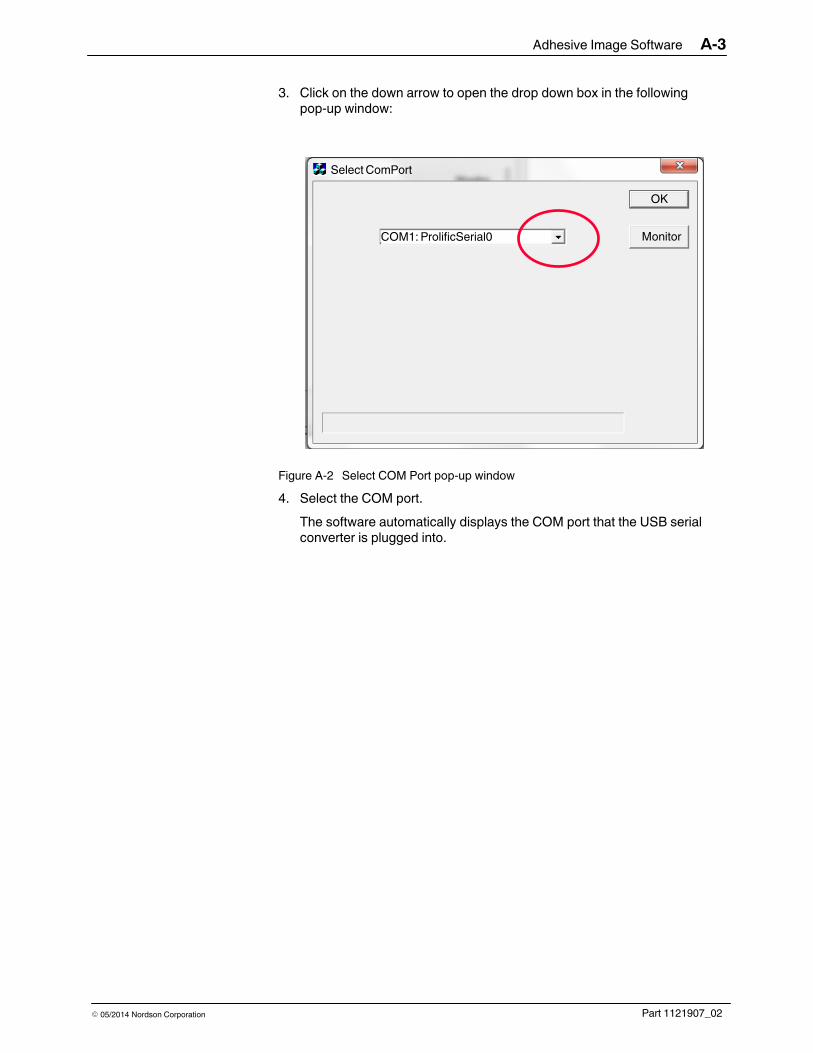
3. Click on the down arrow to open the drop down box in the followingpop-up window:
Select ComPort
OK
MonitorCOM1: ProlificSerial0
Figure A‐2 Select COM Port pop‐up window
4. Select the COM port.
The software automatically displays the COM port that the USB serialconverter is plugged into.

Adhesive Image SoftwareA-4
Part 1121907_02 � 05/2014 Nordson Corporation
Software Setup (contd)
5. Click on the Monitor button again. Doing so shows the adhesive image ofthe previous calibration settings.
GD500 - V2.5 Connected
Monitor
OK
Figure A‐3 Glue image on the pop‐up window
NOTE: All products cannot be displayed because of limited data transferspeed.
Sensor 1 Compensation Setting
Perform the following steps to determine accurate Sensor 1 compensationsettings.
NOTE: Dynamic Calibration removes the factory test state and allows theuser to customize the image settings.
For additional details refer to Dynamic Calibration in the Setup section of themanual for details.
1. Start the production line.

Adhesive Image Software A-5
Part 1121907_02� 05/2014 Nordson Corporation
2. Start the Dynamic Calibration procedure.
The following image appears on the pop‐up window after severalcalibrated product samples have passed under the sensor:
GD500 - V 2.4X Connected
Monitor
OK
1
2
3
Figure A‐4 Image of calibrated products
1. Product with adhesive
2. Product
3. Measurement:Sensor 1 - Sensor 2
3. Pass some product samples under the sensor without adhesive until thepop‐up window is updated with the new settings.
NOTE: Adjust the Compensation Sensor 1 settings if the green (productwith adhesive) and red lines (product) are not stacked together.
4. Perform the Dynamic Calibration procedure and repeat step 3 until thelines are stacked together.
NOTE: The sensors must have a similar response for the same amountof moisture detection.
5. Click on the OK button to close the pop‐up window.

Adhesive Image SoftwareA-6
Part 1121907_02 � 05/2014 Nordson Corporation
Troubleshooting Signal Alignment
WARNING! Allow only qualified personnel to perform the following tasks.Follow the safety instructions in this document and all other relateddocumentation.
The troubleshooting procedures cover common problems that you mayencounter. If you cannot resolve the problems using the following informationcontact your Nordson representative for technical assistance.
This table shows the pop‐up window status in the event of a system errorand provides the possible cause and the typical corrective action.
Pop‐up Window Status Possible Cause Corrective Action
Monitor
OK
GD500 - V 2.4X Connected Wrong delay distancesetting between detectionsensors
Decrease delay setting.
GD500 - V 2.4X Connected
Monitor
OK
Wrong delay distancesetting between detectionsensors
Increase delay setting.

Adhesive Image Software A-7
Part 1121907_02� 05/2014 Nordson Corporation
The delay distance settings between two sensors and the encoder settingsmust be correct. This table provides corrective actions in the event of a delaydistance setting error.
Problem Corrective Action
1. Incorrect encoder setting The setting should be the same as the LogiComm controlsystem. Check if the product length on the LogiComm matches.
2. Incorrect Sensor‐to‐Trigger Offset Check the distance between the GD500 sensor 1 (gluedetection) and the photocell connected to the GD5002controller.

Adhesive Image SoftwareA-8
Part 1121907_02 � 05/2014 Nordson Corporation