universal slice applicator manual -...
TRANSCRIPT

Universal Slice Applicator
Customer Product ManualPart 1072085A02
Issued 3/09
NORDSON CORPORATION • DULUTH, GEORGIA • USAwww.nordson.com
This document contains important safety information
Be sure to read and follow all safety information in thisdocument and any other related documentation.

Part 1072085A02 � 2009 Nordson CorporationAll rights reserved
Nordson Corporation welcomes requests for information, comments, and inquiries about its products. General informationabout Nordson can be found on the Internet using the following address: http://www.nordson.com.
Address all correspondence to:
Nordson CorporationAttn: Customer Service11475 Lakefield DriveDuluth, GA 30097
Notice
This is a Nordson Corporation publication which is protected by copyright. Original copyright date 2007.No part of this document may be photocopied, reproduced, or translated to another language without the prior writtenconsent of Nordson Corporation. The information contained in this publication is subject to change without notice.
Trademarks
AccuJet, AeroCharge, Apogee, AquaGuard, Asymtek, Automove, Baitgun, Blue Box, Bowtie, CanWorks, Century, CF, CleanSleeve, CleanSpray, ColorMax,Color- on- Demand, Control Coat, Coolwave, Cross- Cut, Dispensejet, DispenseMate, DuraBlue, DuraDrum, Durafiber, DuraPail, Dura- Screen,
Durasystem, Easy Coat, Easymove Plus, Ecodry, Econo- Coat, e.dot, EFD, Encore, ESP, e stylized, ETI, Excel 2000, Fillmaster, FlexiCoat, Flex- O- Coat,Flow Sentry, Fluidmove, FoamMelt, FoamMix, Fulfill, HDLV, Heli- flow, Horizon, Hot Shot, iControl, iDry, iFlow, Isocoil, Isocore, Iso- Flo, iTRAX, Kinetix,
LEAN CELL, Little Squirt, LogiComm, Magnastatic, March, Maverick, MEG, Meltex, Microcoat, Micromark, MicroSet, Millennium, Mini Squirt, Mountaingate,MultiScan, Nordson, OptiMix, Package of Values, Pattern View, PermaFlo, Plasmod, Porous Coat, PowderGrid, Powderware, Precisecoat, PRIMARC,Printplus, Prism, ProBlue, Prodigy, Pro- Flo, ProLink, Pro- Meter, Pre- Stream, RBX, Rhino, Saturn, Scoreguard, Seal Sentry, Select Charge, Select Coat,Select Cure, Signature, Slautterback, Smart- Coat, Solder Plus, Spectrum, Speed- Coat, SureBead, Sure Clean, Sure- Max, Sure Wrap, Tracking Plus,TRAK, Trends, Tribomatic, TrueBlue, Ultra, Ultrasaver, UpTime, u-TAH, Vantage, VersaBlue, Versa- Coat, Versa- Screen, Versa- Spray, Watermark,
and When you expect more. are registered trademarks of Nordson Corporation.
Accubar, Advanced Plasma Systems, AeroDeck, AeroWash, AltaBlue, AltaSlot, Alta Spray, AquaCure, ATS, Auto- Flo, AutoScan, Axiom, Best Choice,Blue Series, Bravura, Champion, Check Mate, ClassicBlue, Classic IX, Clean Coat, Controlled Fiberization, Control Weave, ContourCoat, CPX, cScan+,cSelect, Cyclo- Kinetic, DispensLink, DropCure, Dry Cure, DuraBraid, DuraCoat, DuraPUR, Easy Clean, EasyOn, EasyPW, Eclipse, e.dot+, Emerald,E- Nordson, Equi=Bead, FillEasy, Fill Sentry, FlowCoat, Fluxplus, Get Green With Blue, GreenUV, G- Net, G- Site, iON, Iso- Flex, iTrend, Lacquer Cure,
Maxima, Mesa, MicroFin, MicroMax, Mikros, MiniBlue, MiniEdge, Minimeter, MonoCure, Multifil, Myritex, Nano, OptiStroke, Partnership+Plus, PatternJet,PatternPro, PCI, PicoDot, Pinnacle, Powder Pilot, Powder Port, Powercure, Process Sentry, Pulse Spray, Quad Cure, Ready Coat, RediCoat, Royal Blue,Select Series, Sensomatic, Shaftshield, SheetAire, Smart, SolidBlue, Spectral, Spectronic, SpeedKing, Spray Works, Summit, Sure Coat, SureFoam,Sure Mix, SureSeal, Swirl Coat, ThruWave, TinyCure, Trade Plus, Trilogy, TrueCoat, Ultra FoamMix, UltraMax, Ultrasmart, Universal, ValueMate,
VersaDrum, VersaPail, Vista, Web Cure, and 2 Rings (Design) are trademarks of Nordson Corporation.
Designations and trademarks stated in this document may be brands that, when used by third parties for their own purposes,could lead to violation of the owners' rights.
Never Seez is a registered trademark of Bostik Inc.Parker Lubricant is a registered trademark of Parker Seal.
Viton is a registered trademark of DuPont Dow Elastomers. L.L.C.

Table of Contents i
Part 1072085A02� 2009 Nordson Corporation
Table of Contents
Safety 1--1. . . . . . . . . . . . . . . . . . . . . . . . . . . . . . . . . . . . . . . . . . . . . . . . . . . . .Safety Alert Symbols 1--1. . . . . . . . . . . . . . . . . . . . . . . . . . . . . . . . . . . . . . . . .Responsibilities of the Equipment Owner 1--2. . . . . . . . . . . . . . . . . . . . . . .
Safety Information 1--2. . . . . . . . . . . . . . . . . . . . . . . . . . . . . . . . . . . . . . . .Instructions, Requirements, and Standards 1--2. . . . . . . . . . . . . . . . . .User Qualifications 1--3. . . . . . . . . . . . . . . . . . . . . . . . . . . . . . . . . . . . . . .
Applicable Industry Safety Practices 1--3. . . . . . . . . . . . . . . . . . . . . . . . . . .Intended Use of the Equipment 1--3. . . . . . . . . . . . . . . . . . . . . . . . . . . . .Instructions and Safety Messages 1--4. . . . . . . . . . . . . . . . . . . . . . . . . .Installation Practices 1--4. . . . . . . . . . . . . . . . . . . . . . . . . . . . . . . . . . . . . .Operating Practices 1--4. . . . . . . . . . . . . . . . . . . . . . . . . . . . . . . . . . . . . . .Maintenance and Repair Practices 1--5. . . . . . . . . . . . . . . . . . . . . . . . . .
Equipment Safety Information 1--5. . . . . . . . . . . . . . . . . . . . . . . . . . . . . . . .Equipment Shutdown 1--6. . . . . . . . . . . . . . . . . . . . . . . . . . . . . . . . . . . . .
Relieving System Hydraulic Pressure 1--6. . . . . . . . . . . . . . . . . . . . .De--energizing the System 1--6. . . . . . . . . . . . . . . . . . . . . . . . . . . . . . .Disabling the Guns 1--6. . . . . . . . . . . . . . . . . . . . . . . . . . . . . . . . . . . . .
General Safety Warnings and Cautions 1--7. . . . . . . . . . . . . . . . . . . . . .Other Safety Precautions 1--10. . . . . . . . . . . . . . . . . . . . . . . . . . . . . . . . . .First Aid 1--10. . . . . . . . . . . . . . . . . . . . . . . . . . . . . . . . . . . . . . . . . . . . . . . . .
Safety Labels and Tags 1--11. . . . . . . . . . . . . . . . . . . . . . . . . . . . . . . . . . . . . .
Introduction 2--1. . . . . . . . . . . . . . . . . . . . . . . . . . . . . . . . . . . . . . . . . . . . . . . .Product Description 2--2. . . . . . . . . . . . . . . . . . . . . . . . . . . . . . . . . . . . . . . . .
Intended Use 2--3. . . . . . . . . . . . . . . . . . . . . . . . . . . . . . . . . . . . . . . . . . . .Limitations of Use 2--3. . . . . . . . . . . . . . . . . . . . . . . . . . . . . . . . . . . . . . . .Applicator Identification 2--4. . . . . . . . . . . . . . . . . . . . . . . . . . . . . . . . . . . .
Key Components 2--5. . . . . . . . . . . . . . . . . . . . . . . . . . . . . . . . . . . . . . . . . . .Theory of Operation 2--6. . . . . . . . . . . . . . . . . . . . . . . . . . . . . . . . . . . . . . . . .Heating and Temperature Control 2--7. . . . . . . . . . . . . . . . . . . . . . . . . . . . .
Applicator Heaters 2--7. . . . . . . . . . . . . . . . . . . . . . . . . . . . . . . . . . . . . . . .Applicator Temperature Sensors 2--8. . . . . . . . . . . . . . . . . . . . . . . . . . . .
Pressure Monitoring 2--9. . . . . . . . . . . . . . . . . . . . . . . . . . . . . . . . . . . . . . . . .Optional Equipment 2--10. . . . . . . . . . . . . . . . . . . . . . . . . . . . . . . . . . . . . . . . .

Table of Contentsii
Part 1072085A02 � 2009 Nordson Corporation
Installation 3--1. . . . . . . . . . . . . . . . . . . . . . . . . . . . . . . . . . . . . . . . . . . . . . . . .Introduction 3--1. . . . . . . . . . . . . . . . . . . . . . . . . . . . . . . . . . . . . . . . . . . . . . . .Items Needed 3--1. . . . . . . . . . . . . . . . . . . . . . . . . . . . . . . . . . . . . . . . . . . . . .Applicator Installation 3--2. . . . . . . . . . . . . . . . . . . . . . . . . . . . . . . . . . . . . . . .Convert From External to Internal Recirculation 3--4. . . . . . . . . . . . . . . . .Hose Installation 3--6. . . . . . . . . . . . . . . . . . . . . . . . . . . . . . . . . . . . . . . . . . . .Air Supply Installation 3--8. . . . . . . . . . . . . . . . . . . . . . . . . . . . . . . . . . . . . . .
Shared Process Air 3--10. . . . . . . . . . . . . . . . . . . . . . . . . . . . . . . . . . . . . . .Independent Process Air 3--10. . . . . . . . . . . . . . . . . . . . . . . . . . . . . . . . . .
Electrical Installation 3--12. . . . . . . . . . . . . . . . . . . . . . . . . . . . . . . . . . . . . . . .Connect the Cordsets 3--12. . . . . . . . . . . . . . . . . . . . . . . . . . . . . . . . . . . . .Connect the Solenoid Valve Wiring 3--15. . . . . . . . . . . . . . . . . . . . . . . . .
Initial Startup 3--15. . . . . . . . . . . . . . . . . . . . . . . . . . . . . . . . . . . . . . . . . . . . . . .Applicator Flushing 3--16. . . . . . . . . . . . . . . . . . . . . . . . . . . . . . . . . . . . . . . . . .Supply Pressure Adjustment 3--17. . . . . . . . . . . . . . . . . . . . . . . . . . . . . . . . .
Operation 4--1. . . . . . . . . . . . . . . . . . . . . . . . . . . . . . . . . . . . . . . . . . . . . . . . . .Introduction 4--1. . . . . . . . . . . . . . . . . . . . . . . . . . . . . . . . . . . . . . . . . . . . . . . .Startup 4--1. . . . . . . . . . . . . . . . . . . . . . . . . . . . . . . . . . . . . . . . . . . . . . . . . . . .Shutdown 4--2. . . . . . . . . . . . . . . . . . . . . . . . . . . . . . . . . . . . . . . . . . . . . . . . . .
Maintenance 5--1. . . . . . . . . . . . . . . . . . . . . . . . . . . . . . . . . . . . . . . . . . . . . . .Introduction 5--1. . . . . . . . . . . . . . . . . . . . . . . . . . . . . . . . . . . . . . . . . . . . . . . .Maintenance Schedule 5--1. . . . . . . . . . . . . . . . . . . . . . . . . . . . . . . . . . . . . .Filter Screen Replacement 5--2. . . . . . . . . . . . . . . . . . . . . . . . . . . . . . . . . . .
Remove the Filter 5--2. . . . . . . . . . . . . . . . . . . . . . . . . . . . . . . . . . . . . . . .Replace the Filter Screen 5--4. . . . . . . . . . . . . . . . . . . . . . . . . . . . . . . . . .Install the Filter 5--4. . . . . . . . . . . . . . . . . . . . . . . . . . . . . . . . . . . . . . . . . . .
Troubleshooting 6--1. . . . . . . . . . . . . . . . . . . . . . . . . . . . . . . . . . . . . . . . . . . .Introduction 6--1. . . . . . . . . . . . . . . . . . . . . . . . . . . . . . . . . . . . . . . . . . . . . . . .Applicator Heating Problems 6--2. . . . . . . . . . . . . . . . . . . . . . . . . . . . . . . . .Adhesive Output Problems 6--4. . . . . . . . . . . . . . . . . . . . . . . . . . . . . . . . . . .Adhesive Leakage Problems 6--6. . . . . . . . . . . . . . . . . . . . . . . . . . . . . . . . .Pump and Drive Problems 6--7. . . . . . . . . . . . . . . . . . . . . . . . . . . . . . . . . . .Air Supply Problems 6--8. . . . . . . . . . . . . . . . . . . . . . . . . . . . . . . . . . . . . . . . .Pattern Control Problems 6--8. . . . . . . . . . . . . . . . . . . . . . . . . . . . . . . . . . . .
Repair 7--1. . . . . . . . . . . . . . . . . . . . . . . . . . . . . . . . . . . . . . . . . . . . . . . . . . . . .Introduction 7--1. . . . . . . . . . . . . . . . . . . . . . . . . . . . . . . . . . . . . . . . . . . . . . . .Preparation for Repairs 7--2. . . . . . . . . . . . . . . . . . . . . . . . . . . . . . . . . . . . . .Heater Replacement 7--3. . . . . . . . . . . . . . . . . . . . . . . . . . . . . . . . . . . . . . . .Sensor Replacement 7--4. . . . . . . . . . . . . . . . . . . . . . . . . . . . . . . . . . . . . . . .Pressure Transducer Replacement 7--6. . . . . . . . . . . . . . . . . . . . . . . . . . . .Immersion Sensor Replacement 7--8. . . . . . . . . . . . . . . . . . . . . . . . . . . . . .Air Manifold Replacement 7--10. . . . . . . . . . . . . . . . . . . . . . . . . . . . . . . . . . . .Rupture Disk Replacement 7--12. . . . . . . . . . . . . . . . . . . . . . . . . . . . . . . . . . .Motor Rotational Check 7--14. . . . . . . . . . . . . . . . . . . . . . . . . . . . . . . . . . . . . .Applicator Rebuild 7--16. . . . . . . . . . . . . . . . . . . . . . . . . . . . . . . . . . . . . . . . . .
Table of Contents iii
Part 1072085A02� 2009 Nordson Corporation
Parts 8--1. . . . . . . . . . . . . . . . . . . . . . . . . . . . . . . . . . . . . . . . . . . . . . . . . . . . . .Using the Illustrated Parts Lists 8--1. . . . . . . . . . . . . . . . . . . . . . . . . . . . . . .Applicator--Specific Reference Drawing 8--2. . . . . . . . . . . . . . . . . . . . . . . .Service Kits 8--3. . . . . . . . . . . . . . . . . . . . . . . . . . . . . . . . . . . . . . . . . . . . . . . .Tools and Supplies 8--3. . . . . . . . . . . . . . . . . . . . . . . . . . . . . . . . . . . . . . . . . .Slice Applicator Assemblies 8--4. . . . . . . . . . . . . . . . . . . . . . . . . . . . . . . . . .End Plate Assembly Parts 8--6. . . . . . . . . . . . . . . . . . . . . . . . . . . . . . . . . . . .
OSL End Plate 8--6. . . . . . . . . . . . . . . . . . . . . . . . . . . . . . . . . . . . . . . . . . .OSR End Plate 8--8. . . . . . . . . . . . . . . . . . . . . . . . . . . . . . . . . . . . . . . . . . .
External--to--Internal Conversion Kit Parts 8--10. . . . . . . . . . . . . . . . . . . . . . .OSR Recirculation Plate Assembly 8--10. . . . . . . . . . . . . . . . . . . . . . . . .OSL Recirculation Plate Assembly 8--11. . . . . . . . . . . . . . . . . . . . . . . . . .
Middle Plate Assembly Parts 8--12. . . . . . . . . . . . . . . . . . . . . . . . . . . . . . . . .Air Manifold Assembly Parts 8--13. . . . . . . . . . . . . . . . . . . . . . . . . . . . . . . . . .Drive Assembly Parts 8--14. . . . . . . . . . . . . . . . . . . . . . . . . . . . . . . . . . . . . . . .
MPL Inline Drive 8--14. . . . . . . . . . . . . . . . . . . . . . . . . . . . . . . . . . . . . . . . . .MPL Right--Angle Drive 8--15. . . . . . . . . . . . . . . . . . . . . . . . . . . . . . . . . . . .Lenze Inline Drive 8--16. . . . . . . . . . . . . . . . . . . . . . . . . . . . . . . . . . . . . . . .Lenze Right--Angle Drive 8--17. . . . . . . . . . . . . . . . . . . . . . . . . . . . . . . . . . .AC Inline Drive 8--18. . . . . . . . . . . . . . . . . . . . . . . . . . . . . . . . . . . . . . . . . . .AC Right--Angle Drive 8--19. . . . . . . . . . . . . . . . . . . . . . . . . . . . . . . . . . . . .
Pump Assembly Parts 8--20. . . . . . . . . . . . . . . . . . . . . . . . . . . . . . . . . . . . . . .Pump Substitution Block Assembly Parts 8--22. . . . . . . . . . . . . . . . . . . . . . .Filter Assembly Parts 8--23. . . . . . . . . . . . . . . . . . . . . . . . . . . . . . . . . . . . . . . .Pump Shafts 8--24. . . . . . . . . . . . . . . . . . . . . . . . . . . . . . . . . . . . . . . . . . . . . . .Adhesive Diverter Plates 8--25. . . . . . . . . . . . . . . . . . . . . . . . . . . . . . . . . . . . .Temperature Sensors 8--26. . . . . . . . . . . . . . . . . . . . . . . . . . . . . . . . . . . . . . . .
Fixed--Depth Sensors 8--26. . . . . . . . . . . . . . . . . . . . . . . . . . . . . . . . . . . . .Immersion Sensors (Optional) 8--27. . . . . . . . . . . . . . . . . . . . . . . . . . . . . .
Pressure Transducers 8--28. . . . . . . . . . . . . . . . . . . . . . . . . . . . . . . . . . . . . . .Air Input Fittings 8--29. . . . . . . . . . . . . . . . . . . . . . . . . . . . . . . . . . . . . . . . . . . .
Module--Actuating Air Input Fittings 8--29. . . . . . . . . . . . . . . . . . . . . . .Shared Process Air Input Fittings 8--29. . . . . . . . . . . . . . . . . . . . . . . . .
Hose Connector Fittings 8--30. . . . . . . . . . . . . . . . . . . . . . . . . . . . . . . . . . . . .Hose--to--Applicator Fitting Part Numbers 8--30. . . . . . . . . . . . . . . . . . . . .Swivel Fitting Part Numbers 8--31. . . . . . . . . . . . . . . . . . . . . . . . . . . . . . . .Adapter Part Number 8--31. . . . . . . . . . . . . . . . . . . . . . . . . . . . . . . . . . . . . .
Junction Boxes and Connecting Cables 8--32. . . . . . . . . . . . . . . . . . . . . . . .Cordset Junction Boxes 8--32. . . . . . . . . . . . . . . . . . . . . . . . . . . . . . . . . . .Cordset Junction Box Splitter Cable 8--32. . . . . . . . . . . . . . . . . . . . . . . . .Lenze Motor Cables 8--33. . . . . . . . . . . . . . . . . . . . . . . . . . . . . . . . . . . . . .MPL Motor Cables 8--34. . . . . . . . . . . . . . . . . . . . . . . . . . . . . . . . . . . . . . . .AC Motor Cables 8--34. . . . . . . . . . . . . . . . . . . . . . . . . . . . . . . . . . . . . . . . .Pressure Transducer Cables 8--35. . . . . . . . . . . . . . . . . . . . . . . . . . . . . . .M--Style Hose Extension Cables 8--36. . . . . . . . . . . . . . . . . . . . . . . . . . . .T--Style Extension Cables 8--37. . . . . . . . . . . . . . . . . . . . . . . . . . . . . . . . . .T--Style Splitter Cable 8--37. . . . . . . . . . . . . . . . . . . . . . . . . . . . . . . . . . . . .M--Style to T--Style Adapter Cable 8--38. . . . . . . . . . . . . . . . . . . . . . . . . . .
Recommended Spare Parts and Supplies 8--39. . . . . . . . . . . . . . . . . . . . . .

Table of Contentsiv
Part 1072085A02 � 2009 Nordson Corporation
Technical Data 9--1. . . . . . . . . . . . . . . . . . . . . . . . . . . . . . . . . . . . . . . . . . . . .Applicator Specifications 9--1. . . . . . . . . . . . . . . . . . . . . . . . . . . . . . . . . . . . .Applicator Dimensions 9--3. . . . . . . . . . . . . . . . . . . . . . . . . . . . . . . . . . . . . . .Torque Specifications 9--3. . . . . . . . . . . . . . . . . . . . . . . . . . . . . . . . . . . . . . . .Wiring Diagrams 9--4. . . . . . . . . . . . . . . . . . . . . . . . . . . . . . . . . . . . . . . . . . . .
Electrical Schematic 9--4. . . . . . . . . . . . . . . . . . . . . . . . . . . . . . . . . . . . . .Applicator Cordset Pin Positions 9--4. . . . . . . . . . . . . . . . . . . . . . . . . . . .Cordset Junction Boxes 9--6. . . . . . . . . . . . . . . . . . . . . . . . . . . . . . . . . . .Cordset Junction Box Splitter Cable 9--8. . . . . . . . . . . . . . . . . . . . . . . . .Motor Cables 9--9. . . . . . . . . . . . . . . . . . . . . . . . . . . . . . . . . . . . . . . . . . . .Pressure Transducer Cable 9--11. . . . . . . . . . . . . . . . . . . . . . . . . . . . . . . .Extension, Splitter, and Adapter Cables 9--12. . . . . . . . . . . . . . . . . . . . .
Applicator Configuration Code 9--15. . . . . . . . . . . . . . . . . . . . . . . . . . . . . . . .
Modules behind tab. . . . . . . . . . . . . . . . . . . . . . . . . . . . . . . . . . . . . . . . . . . . . . . .
Applicator--Specific behind tab. . . . . . . . . . . . . . . . . . . . . . . . . . . . . . . . . . . . . .
Additional Documentation behind tab. . . . . . . . . . . . . . . . . . . . . . . . . . . . . . .

Safety 1- 1
� 2009 Nordson Corporation Issued 4- 02
Section 1
Safety
Read this section before using the equipment. This section containsrecommendations and practices applicable to the safe installation, operation,and maintenance (hereafter referred to as “ use” ) of the product describedin this document (hereafter referred to as “ equipment” ). Additional safetyinformation, in the form of task- specific safety alert messages, appears asappropriate throughout this document.
WARNING! Failure to follow the safety messages, recommendations, andhazard avoidance procedures provided in this document can result in
personal injury, including death, or damage to equipment or property.
Safety Alert SymbolsThe following safety alert symbol and signal words are used throughout thisdocument to alert the reader to personal safety hazards or to identifyconditions that may result in damage to equipment or property. Comply withall safety information that follows the signal word.
WARNING! Indicates a potentially hazardous situation that, if not avoided,can result in serious personal injury, including death.
CAUTION! Indicates a potentially hazardous situation that, if not avoided,
can result in minor or moderate personal injury.
CAUTION! (Used without the safety alert symbol) Indicates a potentially
hazardous situation that, if not avoided, can result in damage to equipment orproperty.

Safety1- 2
� 2009 Nordson CorporationIssued 4- 02
Responsibilities of the Equipment OwnerEquipment owners are responsible for managing safety information, ensuringthat all instructions and regulatory requirements for use of the equipment aremet, and for qualifying all potential users.
Safety Information� Research and evaluate safety information from all applicable sources,
including the owner- specific safety policy, best industry practices,governing regulations, material manufacturer's product information, andthis document.
� Make safety information available to equipment users in accordance with
governing regulations. Contact the authority having jurisdiction forinformation.
� Maintain safety information, including the safety labels affixed to the
equipment, in readable condition.
Instructions, Requirements, and Standards� Ensure that the equipment is used in accordance with the information
provided in this document, governing codes and regulations, and bestindustry practices.
� If applicable, receive approval from your facility's engineering or safety
department, or other similar function within your organization, beforeinstalling or operating the equipment for the first time.
� Provide appropriate emergency and first aid equipment.
� Conduct safety inspections to ensure required practices are being
followed.
� Re- evaluate safety practices and procedures whenever changes are
made to the process or equipment.

Safety 1- 3
� 2009 Nordson Corporation Issued 4- 02
User Qualifications
Equipment owners are responsible for ensuring that users:
� receive safety training appropriate to their job function as directed by
governing regulations and best industry practices
� are familiar with the equipment owner's safety and accident
prevention policies and procedures
� receive, equipment- and task- specific training from another qualified
individual
NOTE: Nordson can provide equipment- specific installation,operation, and maintenance training. Contact your Nordsonrepresentative for information
� possess industry- and trade- specific skills and a level of experience
appropriate to their job function
� are physically capable of performing their job function and are not
under the influence of any substance that degrades their mentalcapacity or physical capabilities
Applicable Industry Safety PracticesThe following safety practices apply to the use of the equipment in themanner described in this document. The information provided here is notmeant to include all possible safety practices, but represents the best safetypractices for equipment of similar hazard potential used in similar industries.
Intended Use of the Equipment� Use the equipment only for the purposes described and within the limits
specified in this document.
� Do not modify the equipment.
� Do not use incompatible materials or unapproved auxiliary devices.
Contact your Nordson representative if you have any questions onmaterial compatibility or the use of non- standard auxiliary devices.
Safety1- 4
� 2009 Nordson CorporationIssued 4- 02
Instructions and Safety Messages� Read and follow the instructions provided in this document and other
referenced documents.
� Familiarize yourself with the location and meaning of the safety warning
labels and tags affixed to the equipment. Refer to Safety Labels and Tagsat the end of this section.
� If you are unsure of how to use the equipment, contact your Nordson
representative for assistance.
Installation Practices� Install the equipment in accordance with the instructions provided in this
document and in the documentation provided with auxiliary devices.
� Ensure that the equipment is rated for the environment in which it will be
used and that the processing characteristics of the material will not createa hazardous environment. Refer to the Material Safety Data Sheet(MSDS) for the material.
� If the required installation configuration does not match the installation
instructions, contact your Nordson representative for assistance.
� Position the equipment for safe operation. Observe the requirements for
clearance between the equipment and other objects.
� Install lockable power disconnects to isolate the equipment and all
independently powered auxiliary devices from their power sources.
� Properly ground all equipment. Contact your local building code
enforcement agency for specific requirements.
� Ensure that fuses of the correct type and rating are installed in fused
equipment.
� Contact the authority having jurisdiction to determine the requirement for
installation permits or inspections.
Operating Practices� Familiarize yourself with the location and operation of all safety devices
and indicators.
� Confirm that the equipment, including all safety devices (guards,
interlocks, etc.), is in good working order and that the requiredenvironmental conditions exist.
� Use the personal protective equipment (PPE) specified for each task.
Refer to Equipment Safety Information or the material manufacturer'sinstructions and MSDS for PPE requirements.
� Do not use equipment that is malfunctioning or shows signs of a potential
malfunction.

Safety 1- 5
� 2009 Nordson Corporation Issued 4- 02
Maintenance and Repair Practices� Perform scheduled maintenance activities at the intervals described in
this document.
� Relieve system hydraulic and pneumatic pressure before servicing the
equipment.
� De- energize the equipment and all auxiliary devices before servicing the
equipment.
� Use only new factory- authorized refurbished or replacement parts.
� Read and comply with the manufacturer's instructions and the MSDS
supplied with equipment cleaning compounds.
NOTE: MSDSs for cleaning compounds that are sold by Nordson areavailable at www.nordson.com or by calling your Nordson representative.
� Confirm the correct operation of all safety devices before placing the
equipment back into operation.
� Dispose of waste cleaning compounds and residual process materials
according to governing regulations. Refer to the applicable MSDS orcontact the authority having jurisdiction for information.
� Keep equipment safety warning labels clean. Replace worn or damaged
labels.
Equipment Safety InformationThis equipment safety information is applicable to the following types ofNordson equipment:
� hot melt and cold adhesive application equipment and all related
accessories
� pattern controllers, timers, detection and verification systems, and all
other optional process control devices

Safety1- 6
� 2009 Nordson CorporationIssued 4- 02
Equipment Shutdown
To safely complete many of the procedures described in this document, theequipment must first be shut down. The level of shut down required varies bythe type of equipment in use and the procedure being completed.If required, shut down instructions are specified at the start of the procedure.The levels of shut down are:
Relieving System Hydraulic Pressure
Completely relieve system hydraulic pressure before breaking any hydraulicconnection or seal. Refer to the melter- specific product manual forinstructions on relieving system hydraulic pressure.
De- energizing the System
Isolate the system (melter, hoses, guns, and optional devices) from all powersources before accessing any unprotected high- voltage wiring or connectionpoint.
1. Turn off the equipment and all auxiliary devices connected to theequipment (system).
2. To prevent the equipment from being accidentally energized, lock andtag the disconnect switch(es) or circuit breaker(s) that provide inputelectrical power to the equipment and optional devices.
NOTE: Government regulations and industry standards dictate specificrequirements for the isolation of hazardous energy sources. Refer to theappropriate regulation or standard.
Disabling the Guns
All electrical or mechanical devices that provide an activation signal to theguns, gun solenoid valve(s), or the melter pump must be disabled beforework can be performed on or around a gun that is connected to a pressurizedsystem.
1. Turn off or disconnect the gun triggering device (pattern controller, timer,PLC, etc.).
2. Disconnect the input signal wiring to the gun solenoid valve(s).
3. Reduce the air pressure to the gun solenoid valve(s) to zero; then relievethe residual air pressure between the regulator and the gun.

Safety 1- 7
� 2009 Nordson Corporation Issued 4- 02
General Safety Warnings and Cautions
Table 1- 1 contains the general safety warnings and cautions that apply toNordson hot melt and cold adhesive equipment. Review the table andcarefully read all of the warnings or cautions that apply to the type ofequipment described in this manual.
Equipment types are designated in Table 1- 1 as follows:
HM = Hot melt (melters, hoses, guns, etc.)
PC = Process control
CA = Cold adhesive (dispensing pumps, pressurized container, andguns)
Table 1- 1General Safety Warnings and Cautions
EquipmentType Warning or Caution
HM
WARNING! Hazardous vapors! Before processing any polyurethanereactive (PUR) hot melt or solvent- based material through acompatible Nordson melter, read and comply with the material'sMSDS. Ensure that the material's processing temperature andflashpoints will not be exceeded and that all requirements for safehandling, ventilation, first aid, and personal protective equipment aremet. Failure to comply with MSDS requirements can cause personalinjury, including death.
HM
WARNING! Reactive material! Never clean any aluminum componentor flush Nordson equipment with halogenated hydrocarbon fluids.Nordson melters and guns contain aluminum components that mayreact violently with halogenated hydrocarbons. The use of halogenatedhydrocarbon compounds in Nordson equipment can cause personalinjury, including death.
HM, CAWARNING! System pressurized! Relieve system hydraulic pressurebefore breaking any hydraulic connection or seal. Failure to relieve thesystem hydraulic pressure can result in the uncontrolled release of hotmelt or cold adhesive, causing personal injury.
Continued...

Safety1- 8
� 2009 Nordson CorporationIssued 4- 02
General Safety Warnings and Cautions (contd.)
Table 1- 1General Safety Warnings and Cautions (contd)
EquipmentType Warning or Caution
HM
WARNING!Molten material! Wear eye or face protection, clothing thatprotects exposed skin, and heat- protective gloves when servicingequipment that contains molten hot melt. Even when solidified, hot meltcan still cause burns. Failure to wear appropriate personal protectiveequipment can result in personal injury.
HM, PC
WARNING! Equipment starts automatically! Remote triggering devicesare used to control automatic hot melt guns. Before working on or nearan operating gun, disable the gun's triggering device and remove theair supply to the gun's solenoid valve(s). Failure to disable the gun'striggering device and remove the supply of air to the solenoid valve(s)can result in personal injury.
HM, CA, PC
WARNING! Risk of electrocution! Even when switched off andelectrically isolated at the disconnect switch or circuit breaker, theequipment may still be connected to energized auxiliary devices.De- energize and electrically isolate all auxiliary devices beforeservicing the equipment. Failure to properly isolate electrical power toauxiliary equipment before servicing the equipment can result inpersonal injury, including death.
HM, CA, PC
WARNING! Risk of fire or explosion! Nordson adhesive equipment isnot rated for use in explosive environments and should not be usedwith solvent- based adhesives that can create an explosiveatmosphere when processed. Refer to the MSDS for the adhesive todetermine its processing characteristics and limitations. The use ofincompatible solvent- based adhesives or the improper processing ofsolvent- based adhesives can result in personal injury, including death.
Continued...

Safety 1- 9
� 2009 Nordson Corporation Issued 4- 02
Table 1- 1General Safety Warnings and Cautions (contd)
EquipmentType Warning or Caution
HM, CA, PC
WARNING! Allow only personnel with appropriate training andexperience to operate or service the equipment. The use of untrainedor inexperienced personnel to operate or service the equipment canresult in injury, including death, to themselves and others and candamage to the equipment.
HM
CAUTION! Hot surfaces! Avoid contact with the hot metal surfaces ofguns, hoses, and certain components of the melter. If contact can notbe avoided, wear heat- protective gloves and clothing when workingaround heated equipment. Failure to avoid contact with hot metalsurfaces can result in personal injury.
HM
CAUTION! Some Nordson melters are specifically designed toprocess polyurethane reactive (PUR) hot melt. Attempting to processPUR in equipment not specifically designed for this purpose candamage the equipment and cause premature reaction of the hot melt. Ifyou are unsure of the equipment's ability to process PUR, contact yourNordson representative for assistance.
HM, CA
CAUTION! Before using any cleaning or flushing compound on or inthe equipment, read and comply with the manufacturer's instructionsand the MSDS supplied with the compound. Some cleaningcompounds can react unpredictably with hot melt or cold adhesive,resulting in damage to the equipment.
HM
CAUTION! Nordson hot melt equipment is factory tested with NordsonType R fluid that contains polyester adipate plasticizer. Certain hot meltmaterials can react with Type R fluid and form a solid gum that canclog the equipment. Before using the equipment, confirm that the hotmelt is compatible with Type R fluid.

Safety1- 10
� 2009 Nordson CorporationIssued 4- 02
Other Safety Precautions� Do not use an open flame to heat hot melt system components.
� Check high pressure hoses daily for signs of excessive wear, damage, or
leaks.
� Never point a dispensing handgun at yourself or others.
� Suspend dispensing handguns by their proper suspension point.
First Aid
If molten hot melt comes in contact with your skin:
1. Do NOT attempt to remove the molten hot melt from your skin.
2. Immediately soak the affected area in clean, cold water until the hot melthas cooled.
3. Do NOT attempt to remove the solidified hot melt from your skin.
4. In case of severe burns, treat for shock.
5. Seek expert medical attention immediately. Give the MSDS for the hotmelt to the medical personnel providing treatment.

Safety 1- 11
� 2009 Nordson Corporation Issued 4- 02
Safety Labels and TagsFigure 1- 1 illustrates the location of the product safety labels and tagsaffixed to the equipment. Table 1- 2 provides an illustration of the hazardidentification symbols that appear on each safety label and tag, the meaningof the symbol, or the exact wording of any safety message.
1
22
1
Figure 1- 1 Safety labels and tags
Table 1- 2 Safety Labels and Tags
Item Part Description
1. 181863
Plate, warning, CE, electrical shock
2. 181862
Plate, warning, CE, hot

Safety1- 12
� 2009 Nordson CorporationIssued 4- 02

Introduction 2- 1
Part 1072085A02� 2009 Nordson Corporation
Section 2
Introduction
This manual describes the installation and use of the Universal slice meteringapplicator. When necessary, the reader is referred to the documentationsupplied with other Nordson products or products supplied by third parties.
Universal slice applicators are configurable, which means each applicator isconstructed according to specific choices made during the ordering process.Reference drawings specific to your applicator are provided with this manual.
Figure 2- 1 Typical Universal slice applicators (twelve- module applicator with an inline drive and a right- angle driveshown)

Introduction2- 2
Part 1072085A02 � 2009 Nordson Corporation
Product DescriptionThe Universal slice applicator is used in conjunction with an adhesive supplysystem and Nordson hot melt hoses to create a hot melt application system.The applicator receives liquified hot melt material from an adhesive supplyand applies it to various products. Figure 2- 2 shows how the applicator istypically integrated into a hot melt system.
Two- Zone Extension Cable
Adhesive Return Hose
End ZonesCenter Zones
Adhesive Supply Hose
Figure 2- 2 Diagram of a typical hot melt application system using a Universal slice applicator

Introduction 2- 3
Part 1072085A02� 2009 Nordson Corporation
Intended Use
Universal slice applicators are specifically designed to:
� pump liquified materials at temperatures below 204 �C (400 �F)
� be used with compatible hot melt equipment manufactured by
Nordson Corporation
� be used in non- explosive environments
Limitations of Use
Use Universal slice applicators only for the purpose for which they aredesigned. They should not be used:
� to pump polyurethane reactive hot melt materials or any other
material that creates a health or safety hazard when heated
� in environments that will require the equipment to be cleaned using a
water wash or spray

Introduction2- 4
Part 1072085A02 � 2009 Nordson Corporation
Applicator Identification
See Figure 2- 3. You will need the model and part number of your applicatorwhen requesting service or ordering spare parts and optional equipment. Themodel and part number are indicated on the equipment identification plate.
Figure 2- 3 Location of the equipment identification plate on a Universal sliceapplicator

Introduction 2- 5
Part 1072085A02� 2009 Nordson Corporation
Key Components
1
2
3
11
15
14
13
6
7
10
12
8
9
5
4
Figure 2- 4 Key parts of a Universal slice applicator (twelve- module applicator with inline drive shown)
1. Motor and reducer
2. Temperature sensor
3. Pumps
4. Supply hose fitting
5. Filter
6. Heater
7. End plate (right)
8. Pressure transducer (post- filter)
9. Rupture disk
10. Air manifolds
11. Dispensing modules
12. Middle plate
13. End plate (left)
14. Return hose fitting
15. Pressure transducer(drive- side)
Note: The front of the applicator is always the side on which the modules are installed.
Introduction2- 6
Part 1072085A02 � 2009 Nordson Corporation
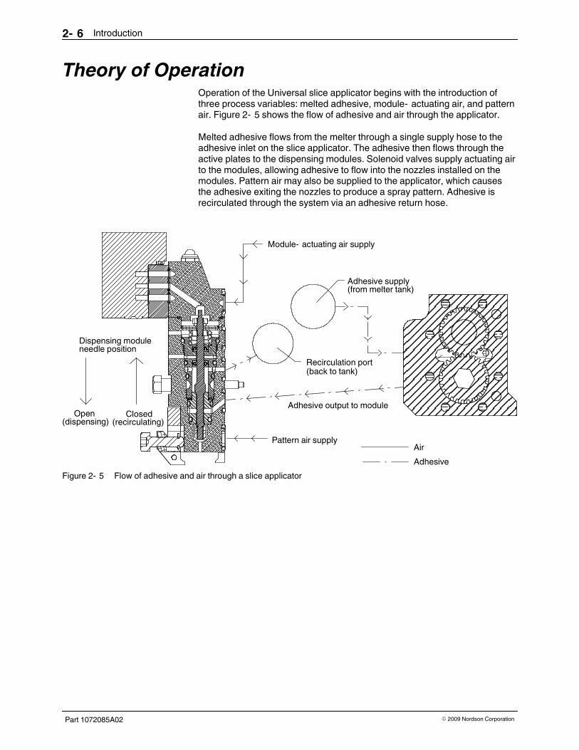
Theory of OperationOperation of the Universal slice applicator begins with the introduction ofthree process variables: melted adhesive, module- actuating air, and patternair. Figure 2- 5 shows the flow of adhesive and air through the applicator.
Melted adhesive flows from the melter through a single supply hose to theadhesive inlet on the slice applicator. The adhesive then flows through theactive plates to the dispensing modules. Solenoid valves supply actuating airto the modules, allowing adhesive to flow into the nozzles installed on themodules. Pattern air may also be supplied to the applicator, which causesthe adhesive exiting the nozzles to produce a spray pattern. Adhesive isrecirculated through the system via an adhesive return hose.
Dispensing module
Open(dispensing)
Closed(recirculating)
Adhesive output to module
Recirculation port(back to tank)
Adhesive supply(from melter tank)
Module- actuating air supply
Pattern air supplyAir
Adhesive
needle position
Figure 2- 5 Flow of adhesive and air through a slice applicator

Introduction 2- 7
Part 1072085A02� 2009 Nordson Corporation
Heating and Temperature ControlHeating and temperature control of the Universal slice applicator areaccomplished by replaceable heaters and temperature sensors. The heatersand sensors are connected to the melter using cordset junction boxes andextension and splitter cables. Figure 2- 2 shows a typical system layout.
Applicator Heaters
Heating of the adhesive and air (if used) that flows through the applicator isaccomplished by cartridge- type heaters. One heater is present on each endplate and and additional heater is present for each 50 mm of applicator. Anapplicator may have a maximum of six heated zones. All heaters have aquick- disconnect plug. Figure 2- 6 shows the location of the heaters on anapplicator.
Figure 2- 6 Location of the applicator heaters (typical twelve- module applicatorshown)

Introduction2- 8
Part 1072085A02 � 2009 Nordson Corporation
Applicator Temperature Sensors
Temperature sensing and control is accomplished through resistancetemperature detectors (RTDs). Each temperature sensor is installed in aquick- change, bayonet- style thermowell. Each end plate is a heated zonethat always consists of one heater and one temperature sensor. Onetemperature sensor is then used for a maximum of three 50- mm middleplates, meaning that each middle plate heated zone can consist of one tothree heaters. Figure 2- 7 shows the location of the sensors on theapplicator.
The temperature sensors on your applicator may be 100- ohm platinum or120- ohm nickel. An immersion temperature sensor that senses the actualtemperature of the adhesive entering the applicator may also be present.Refer to Applicator Configuration Code in Section 9, Technical Data, todetermine the configuration of your applicator.
3
1
2
Figure 2- 7 Location of temperature sensors (typical twelve- module applicatorshown)
1. Left end plate temperature sensor
2. Middle plate temperature sensor
3. Right end plate temperaturesensor

Introduction 2- 9
Part 1072085A02� 2009 Nordson Corporation
Pressure MonitoringThe pressure transducers present on the applicator allow you to monitor thehydraulic pressure as follows:
� The post- filter and drive- side pressure transducers monitor the
pressure of the adhesive flow after the filter but before the pumps.These two transducers are used to compare the pressure beingsupplied by the melter and the pressure on the opposite side of theapplicator to ensure an adequate supply of adhesive to the pumps.
� If desired, you can install a pressure transducer in any pump to
monitor the pressure of the adhesive flow between the pump outputand the module (this is known as the application pressure). Trackingthis pressure reading provides additional diagnostic capability topredict module failure or nozzle clogging.
Pressure transducers are connected to the customer's pressure monitoringequipment (melter control system, auxiliary control module, etc.) via pressuretransducer cables and extension cables.
The pressure transducer signal for your applicator may be 4-20 mA or0-10 VDC. Refer to Applicator Configuration Code in Section 9, TechnicalData, to determine the configuration of your applicator.
Figure 2- 8 shows the location of the pressure transducers.
1
2
3
Figure 2- 8 Location of pressure transducers
1. Drive- side pressure transducer
2. Post- filter pressure transducer
3. Location where an optionalpressure transducer can beinstalled in a pump

Introduction2- 10
Part 1072085A02 � 2009 Nordson Corporation
Optional EquipmentOptional equipment may be ordered to expand the functionality of theUniversal slice applicator, including, but not limited to, the following:
� a pump substitution block that may be installed in any pump location
to block the adhesive flow from that location
Refer to Section 8, Parts, for a complete list of optional equipment.
NOTE: Dispensing module options are documented in the module productmanual.

Installation 3- 1
Part 1072085A02� 2009 Nordson Corporation
Section 3
Installation
WARNING! Allow only personnel with appropriate training and experience to
operate or service the equipment. The use of untrained or inexperienced
personnel to operate or service the equipment can result in injury, including
death, to themselves and others, and damage to the equipment.
IntroductionThis section provides procedures for installing the applicator and preparing itfor initial operation.
Items NeededYou will need the following items to install the applicator:
� personal protective equipment for working with hot adhesive
� drain pans and waste containers suitable for waste adhesive
� device to lift and position the applicator
� heated hydraulic hoses
� air line tubing (8- mm, 10- mm, and 12- mm internal diameter or
larger)
� set of standard and metric hex- head wrenches
� flat- blade and Phillips- head screwdrivers
� O- ring lubricant
� anti- seize lubricant

Installation3- 2
Part 1072085A02 � 2009 Nordson Corporation
Applicator Installation1. Carefully unpack the applicator and inspect if for any damage that may
have occurred during shipping. Report any damage to your Nordsonrepresentative.
2. Select a mounting location that
� provides enough clearance to service the applicator
NOTE: Refer to the applicator- specific reference drawing for theapplicator dimensions and clearances.
� will not subject the applicator to extreme vibration or temperature
variations
� will allow you to properly route hoses (see Figure 3- 4)
� is close to a supply of dry, regulated, unlubricated air
� will allow you to adjust the distance and/or angle between the
applicator and the product surface
3. Move the applicator into the position where it will be mounted. Refer tothe applicator- specific reference drawing for the weight of the applicator.
4. See Figure 3- 1. Mount the applicator on the production line usingM10 bolts in the mounting holes in the end plates. Be sure to install theinsulators to prevent heat loss into the mounting blocks.
Figure 3- 1 Location of the insulators on the applicator

Installation 3- 3
Part 1072085A02� 2009 Nordson Corporation
This page intentionally left blank.

Installation3- 4
Part 1072085A02 � 2009 Nordson Corporation
Convert From External to Internal RecirculationIf needed for your application, use the recirculation plate assembly providedwith the applicator to convert the applicator from external recirculation tointernal recirculation. External recirculation is recommended for intermittentapplications. Internal recirculation is recommended for continuousapplications.
Refer to the applicator- specific reference drawing for conversion illustrationsspecific to your applicator.
CAUTION! Risk of equipment damage. Ensure that all components are clean
and free of debris before assembly. Take care to prevent damage to O- rings
seals during installation.
See Figure 3- 2.
1. Remove the O- ring plug (1) and rupture disk assembly (2) from theapplicable end plate.
2. Apply anti- seize lubricant to the recirculation plate assembly (4, 5)screws and install the assembly on the end plate. Tighten the screws to12.4 N�m (110 in.- lb).
3. Remove the hose fitting (3) and install the previously removed rupturedisk in the hose fitting port. Tighten the rupture disk to 5.6 N�m(50 in.- lb).

Installation 3- 5
Part 1072085A02� 2009 Nordson Corporation
3
5
4
1, 2
1
2
12.4 N�m (110in.- lb)
5.6 N�m (50in.- lb)
Figure 3- 2 Converting from external to internal recirculation (typical)
1. O- ring plug
2. Rupture disk assembly
3. Hose fitting
4. OSL recirculation plate assembly
5. OSR recirculation plateassembly
Note: A typical OSL applicator is shown in this illustration. Refer to the applicator- specific reference drawing for anillustration specific to your applicator.

Installation3- 6
Part 1072085A02 � 2009 Nordson Corporation
Hose InstallationThroughout the hose installation process, follow the guidelines shown inFigure 3- 4.
CAUTION! Improper routing and venting of hoses could result inoverheating, damage, and poor adhesive flow. To ensure proper operation,
do not bundle or tie- wrap the hoses, do not bend the hoses at sharp angles,
and do not allow the hoses to lay on concrete floors or other cool surfacesthat could conduct heat away from a hose.
1. See Figure 3- 3. Use two wrenches to connect the adhesive supply hoseto the adhesive input port (1) and, if applicable, the adhesive return hoseto the recirculation port (2).
NOTE: Hose cordsets should be located at the melter end (whereadhesive enters the hose). This ensures that the hose sensor measuresthe temperature of the adhesive exiting the hose.
2. Route the hoses from the applicator to the melter.
3. Connect the supply and return hoses to the melter. Refer to the meltermanual as needed.
NOTE: During intermittent operation, all unused adhesive will becirculated back to the melter through the return hose.
1
2
Figure 3- 3 Location of the adhesive input and recirculation ports
1. Adhesive input port 2. Adhesive recirculation port

Installation 3- 7
Part 1072085A02� 2009 Nordson Corporation
450000002
P/N 111 940
X=13 mm (0.50 in.)
R=203 mm (8.00 in.)
P/N 271 486 - 8 mm (5/16 in.)P/N 274 174 - 16 mm (5/8 in.)
X
P/N 274 174 - 29 mm (1 1/8 in.)
Figure 3- 4 Hose installation guidelines

Installation3- 8
Part 1072085A02 � 2009 Nordson Corporation
Air Supply InstallationConnect a supply of clean, dry, unlubricated air to the applicator for moduleair actuation and shared or independent process (pattern) air, as applicable.Refer to Table 3- 1.
The applicator may be configured for shared or independent process air.Refer to Applicator Configuration Code in Section 9, Technical Data, todetermine the configuration of your applicator. Refer to Shared Process Airand Independent Process Air on the next page for an explanation of theseconcepts.
NOTE: Nordson Corporation recommends the installation of a 5- microncoalescing pre- filter.
NOTE: For recommended air supply operating pressures, refer to ApplicatorSpecifications in Section 9, Technical Data.
Table 3- 1 Air Supply Connections
Item No. inFig. 3- 5
Type of Air Supply PurposeComments
1 Module- actuating air To open and closethe modules
Each 50- mm plate has an air input port.To ensure optimal intermittent moduleperformance, Nordson Corporationrecommends connecting a centeredmodule- actuating air supply line for each150 mm of applicator width.
2 Process air To provide the air forspray applications
On applicators with shared process air,the air input ports located on the end plateare used. On applicators with independentprocess air, an air input port is alsopresent on each air manifold.

Installation 3- 9
Part 1072085A02� 2009 Nordson Corporation
2
10 mm
12 mmG 3/8BSPP 3/8
G 1/4BSPP 1/4
1
Figure 3- 5 Location of air supply connections
1. Module- actuating air inputs 2. Process air inputs (shared air inputshown)
Note: The air line size for an air manifold with an independent air supply port (not shown) is 8 mm. The thread size isG 1/8, or BSPP
1/8.
Installation3- 10
Part 1072085A02 � 2009 Nordson Corporation
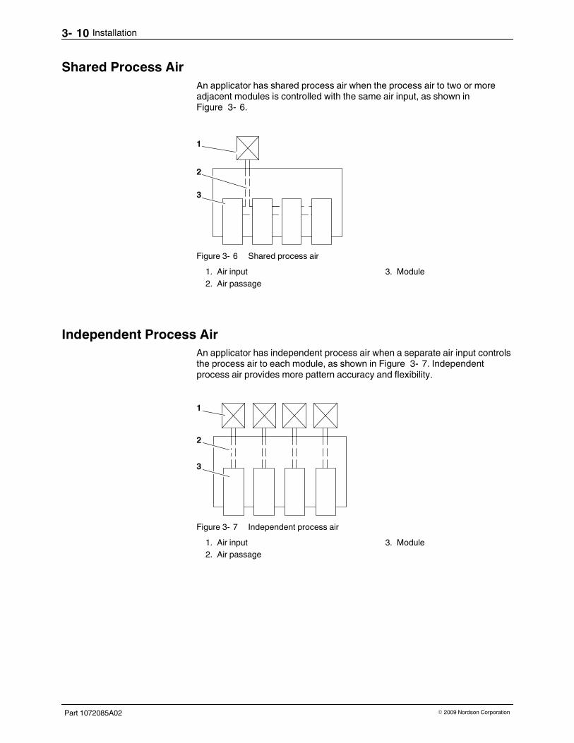
Shared Process Air
An applicator has shared process air when the process air to two or moreadjacent modules is controlled with the same air input, as shown inFigure 3- 6.
1
2
3
Figure 3- 6 Shared process air
1. Air input
2. Air passage
3. Module
Independent Process Air
An applicator has independent process air when a separate air input controlsthe process air to each module, as shown in Figure 3- 7. Independentprocess air provides more pattern accuracy and flexibility.
1
2
3
Figure 3- 7 Independent process air
1. Air input
2. Air passage
3. Module

Installation 3- 11
Part 1072085A02� 2009 Nordson Corporation
This page intentionally left blank.

Installation3- 12
Part 1072085A02 � 2009 Nordson Corporation
Electrical InstallationElectrical installation includes connecting cordsets and connecting thesolenoid valve wiring.
Connect the Cordsets
Connect the applicator cordsets shown in Table 3- 2 to the appropriatecontrol equipment, such as a melter or an ACM (auxiliary control module).You will need extension, splitter, motor, and pressure transducer cables asappropriate for your operation. Refer to the control equipment documentationor contact your Nordson representative for assistance as needed.
NOTE: Figure 3- 8 shows the location of the cordsets. Figure 3- 9 is adiagram of typical cordset connections.
NOTE: Refer to Section 8, Parts, for cable part numbers.
Table 3- 2 Applicator Cordsets (see Figure 3- 8)
Component Connect to... And then connect to...
End plate heater and sensorcordsets
End zone cordset junction boxes(See Note)
Melter or controller usingextension cable
Middle plate heater and sensorcordsets
Center zone cordset junctionboxes (See Note)
Melter or controller using splittercables and extension cables
Motor cordset Melter or control equipment Not applicable
Pressure transducer cordsets Pressure transducer cables Melter or control equipment
Immersion sensor cordset (ifpresent)
Customer- supplied monitoringequipment
Not applicable
Hose cordsets Melter or control equipment Not applicable
NOTE: A center zone cordset junction box allows control of one heated zone. An end zone cordsetjunction box allows control of two separate heated zones. Refer to the wiring diagrams provided in Section9, Technical Data, as needed when connecting the applicator's heated zones to your control equipment.

Installation 3- 13
Part 1072085A02� 2009 Nordson Corporation
5
13
2
4
5
1
2
Figure 3- 8 Applicator cordsets
1. End plate temperature sensor
2. End plate heater
3. Middle plate temperature sensor
4. Middle plate heater
5. Pressure transducer(adhesive input)
Note: The immersion sensor is not shown.

Installation3- 14
Part 1072085A02 � 2009 Nordson Corporation
Connect the Cordsets (contd.)
Two- Zone Extension Cable
Adhesive Return Hose
End ZonesCenter Zones
Adhesive Supply Hose
Nordson
Figure 3- 9 Diagram of typical applicator cordset connections

Installation 3- 15
Part 1072085A02� 2009 Nordson Corporation
Connect the Solenoid Valve Wiring
Connect the solenoid valve wiring to the control equipment (such as aPLC/PLS or pattern controller) that will send the signal to actuate themodules. Ensure that the connectors are compatible. Refer to the controlequipment documentation.
Initial StartupBefore operating the applicator for the first time, follow these steps to ensurethat the applicator was properly installed and to prepare it for flushing andsupply pressure adjustment.
1. Apply power to the applicator.
2. Set the temperatures for the applicator's heated zones (end plates andmiddle plates).
NOTE: Refer to the adhesive's technical data sheet for therecommended application temperature.
3. Turn on the module- actuating air and set the pressure.
4. If applicable, turn on the pattern air and set the pressure.
NOTE: Refer to Applicator Specifications in Section 9, Technical Data,for air pressure specifications.
5. Apply the module- actuation signal to the solenoid valves to test theadhesive output.
6. When the system has reached application temperature, set the applicatorpump speed and start the pump.
NOTE: Refer to Applicator Specifications in Section 9, Technical Data,for the minimum, maximum, and recommended pump speeds.
7. Start the production line.
CAUTION! Operation of the applicator when the rotational direction of thepump shaft is incorrect will result in no adhesive output, and could damage
the pumps.
8. If there is no adhesive output, stop the melter and applicator pumps andrefer to Motor Rotational Check in Section 7, Repair, to verify that thepump shaft is rotating in the correct direction. Return here to continue.
9. When the applicator is applying adhesive properly, continue to the nextprocedure to flush the applicator.

Location of pressure relief valve
Installation3- 16
Part 1072085A02 � 2009 Nordson Corporation
Applicator FlushingFlushing the applicator removes fluid, cleaning solution, adhesive, and othercontaminants. Flushing also helps to prevent clogging of the filter or nozzlesand makes the applicator work more efficiently. The applicator should beflushed
� before initial use
� anytime you change the adhesive in the hot melt system
Refer to the melter manual as needed for the procedures for operating themelter.
1. Heat the system to application temperature.
2. Disconnect a hose from the applicator, start the melter pump, and flushadhesive through the hose into a waste container until the adhesive flowsclear. Stop the melter pump and reconnect the hose.
3. Place a drain pan under the applicator pressure relief valve.
4. Open the applicator pressure relief valve by turning the valve screw oneturn counterclockwise.
5. Start the melter pump and increase the speed as needed until adhesiveflows from the pressure relief valve.
6. When the adhesive flowing from the pressure relief valve is clear, stopthe melter pump.
7. Tighten the applicator pressure relief valve screw to close the valve.
8. Open all the dispensing modules, start the melter pump, and flushadhesive through them into a waste container until the adhesive is clear.Stop the melter pump and close the modules.
9. Continue to the next procedure to adjust the system supply pressure.

Installation 3- 17
Part 1072085A02� 2009 Nordson Corporation
Supply Pressure AdjustmentSlice applicators are equipped with positive- displacement pumps to providelocalized metering of the adhesive at the point of application. To ensure thebest performance in metering accuracy, it is important to understand how toproperly setup the adhesive supply to the applicator.
About positive- displacement pumps
Positive- displacement- type metering pumps are the type of pump used onmost “ metered” hot melt equipment. These pumps are manufactured to avery tight set of tolerances with regard to how the metering gears fit into theirrespective internal glands, which is why they are calledpositive- displacement pumps.
However, even though the fit of the gears is extremely tight (~ 50 millionths ofan inch), a gap does exist between them. Therefore, to gain the best possibleperformance from this type of pump, it is desirable to minimize the amount ofdifferential pressure between the pump inlet and outlet. The higher thedifferential pressure, the more fluid (adhesive, etc.) you will have to passthrough this gap. This has a greater effect for low viscosity adhesives.
The fluid supply pressure needed to adequately feed apositive- displacement pump is relatively low. The main goal is simply tokeep the pump full of adhesive, primarily to provide adequate lubrication tothe gears to prevent seizure.
To ensure that the supply pressure is set correctly for your application needs,complete the steps in the following supply pressure adjustment procedure.

Installation3- 18
Part 1072085A02 � 2009 Nordson Corporation
Supply pressure adjustment
1. Disable the applicator.
2
3
1
Figure 3- 10 Location of pressure transducers
1. Post- filter pressure transducer
2. Drive- side pressure transducer
3. Location where an optionalpressure transducer can beinstalled in a pump
2. As a starting point, set the adhesive supply unit (melter, remote meteringstation, etc.) to supply 110% of the adhesive consumption of the sliceapplicator.
NOTE: To correctly calculate the applicator's adhesive consumption, youmust consider the following:
Pump capacity— Add up all the individual pump capacities of yourapplicator. Example: eight pumps at 0.584 cc/rev per pump =4.672 cc/rev total.
Pump shaft rpm— A common shaft is used to drive all the applicatorpumps
Pattern being produced— If an intermittent pattern is being used, theduty cycle (percentage of actual dispensing time of the pattern) should beincluded in your calculation. (for example, a 50- percent duty cycle for agiven slice position would drop that pump's flow requirement by half).
To set the rate of adhesive supply, adjust the rpm of the supply pumpaccordingly based on its size (cc/rev).
Installation 3- 19
Part 1072085A02� 2009 Nordson Corporation
3. Run the system in actual production mode.
NOTE: The pump rpms should replicate full production line speeds toprovide accurate flow rates and pressures.
NOTE: If an intermittent pattern is being used, the applicator should bedispensing the exact pattern desired, as it would be in actual production.
4. Set the pressure adjustment on the adhesive supply unit as follows:
a. Start the adhesive supply unit with its pressure control valve (PCV) atthe lowest position.
b. Slowly adjust the PCV to gradually increase the output pressure of thesupply unit.
c. Monitor both pressure indications (pressure transducer readings) onthe slice applicator. You will first notice a pressure rise on the filter(inlet) side.
d. After allowing adequate time for the system to stabilize, begin raisingthe inlet pressure slowly until the pressure transducer on the oppositeend of the slice applicator reads the same as the transducer on theinlet side [+/- 1 bar (14.5 psi)]. Allow the system to stabilize after eachadjustment, and recheck your pressure readings.
e. When both transducer readings are the same, there is adequatepressure within the supply channel to fill all the pumps in the sliceapplicator.
NOTE: It is acceptable to increase the supply pressure by 1 bar (14.5psi) above this equalization point to ensure that the supply pressuredoes not drop below the required level to keep the supply channelfull. Slightly higher pressure settings may need to be consideredbased on capability of the supply system to maintain a consistent flowrate.
Example: AC motors running at slow speeds produce a wider swing inrpm, producing a higher variability in flow rate.
Installation3- 20
Part 1072085A02 � 2009 Nordson Corporation
Supply Pressure Adjustment (contd.)
Summary
After following the above procedure, you are now ready to run in actualproduction. If any changes to pump size, pump rpm, or intermittent patternsize occur, you must repeat this procedure to ensure the correct supplypressure.
To gain the best possible control of the supply pressure at the applicator,Nordson Corporation recommends a “ closed- loop” control scheme,described in detail below.
Closed- loop control scheme
Most applicators are several feet away from their adhesive supply source,requiring heated hoses to transfer the molten adhesive to the applicator. Asdiscussed above, the supply pressure to the applicator is adjusted with thepressure control valve (PCV) at the supply source, which is several feetaway. The greater this distance is, the more time it takes for an increase inpressure at the applicator to reach the PCV at the supply source, thusrelieving the overpressure condition.
Due to this time lag, there is a constant fluctuation in pressure at theapplicator that in turn constantly changes the pressure differential betweenthe pump inlet and outlet. To keep this fluctuation to a minimum, use thepressure transducer on the applicator to control the rpm of the pump on thesupply source. This method provides a digital signal to the motor drivecontrol, allowing it to adjust the supply pump rpm accordingly to maintain thecorrect pressure at the applicator. This has proved to be a much fasterresponse than the PCV approach, and greatly reduces the pressurevariation.

Operation 4- 1
Part 1072085A02� 2009 Nordson Corporation
Section 4
Operation
WARNING! Allow only personnel with appropriate training and experience to
operate or service the equipment. The use of untrained or inexperienced
personnel to operate or service the equipment can result in injury, including
death, to themselves and others, and damage to the equipment.
IntroductionThis section provides procedures for operating the applicator. Before youoperate the applicator for the first time, make sure you have
� completed the installation procedures in Section 3, Installation
� completed the initial startup, applicator flushing, and supply pressure
adjustment procedures in Section 3, Installation
StartupProcedures for starting and stopping the applicator vary depending on thetype of melter you are using. Refer to the melter manual for complete startupand shutdown procedures.
1. Heat the system to application temperature.
2. Turn on the module- actuating air.
3. Turn on the pattern air.
NOTE: Recommended settings for the module- actuating air pressure,pattern air pressure, and system hydraulic pressure are provided inApplicator Specifications in Section 9, Technical Data.
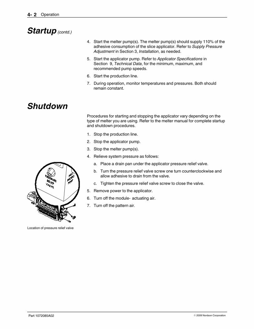
Location of pressure relief valve
Operation4- 2
Part 1072085A02 � 2009 Nordson Corporation
Startup (contd.)
4. Start the melter pump(s). The melter pump(s) should supply 110% of theadhesive consumption of the slice applicator. Refer to Supply PressureAdjustment in Section 3, Installation, as needed.
5. Start the applicator pump. Refer to Applicator Specifications inSection 9, Technical Data, for the minimum, maximum, andrecommended pump speeds.
6. Start the production line.
7. During operation, monitor temperatures and pressures. Both shouldremain constant.
ShutdownProcedures for starting and stopping the applicator vary depending on thetype of melter you are using. Refer to the melter manual for complete startupand shutdown procedures.
1. Stop the production line.
2. Stop the applicator pump.
3. Stop the melter pump(s).
4. Relieve system pressure as follows:
a. Place a drain pan under the applicator pressure relief valve.
b. Turn the pressure relief valve screw one turn counterclockwise andallow adhesive to drain from the valve.
c. Tighten the pressure relief valve screw to close the valve.
5. Remove power to the applicator.
6. Turn off the module- actuating air.
7. Turn off the pattern air.

Maintenance 5- 1
Part 1072085A02� 2009 Nordson Corporation
Section 5
Maintenance
WARNING! Allow only personnel with appropriate training and experience to
operate or service the equipment. The use of untrained or inexperiencedpersonnel to operate or service the equipment can result in injury, including
death, to themselves and others, and damage to the equipment.
IntroductionThis section contains a recommended maintenance schedule andprocedures for properly maintaining your applicator. Attempting any othermaintenance procedures can result in equipment damage, improper systemoperation, or personal injury.
Maintenance ScheduleTable 5- 1 provides recommended maintenance activities and a schedule forperforming those activities. Base how often you perform maintenance onyour operating conditions.
Table 5- 1 Recommended Maintenance Activities and Schedule
Frequency Maintenance Activity
Daily � Keep the supply of adhesive clean and free of contaminants. Foreign particlesin the adhesive can block the filter or nozzles.
� Check the hose connection for leaks. If a leak is found, replace the hose fittingand/or O- ring as appropriate.
As needed � Verify that all electrical connections are secure. Vibration and heating orcooling cycles can loosen cordset and cable connections.
� Replace the filter. Refer to Filter Screen Replacement in this section.
� Clean nozzles. Refer to the nozzle cleaning procedure in the moduledocumentation.
Maintenance5- 2
Part 1072085A02 � 2009 Nordson Corporation
Filter Screen ReplacementReplace the filter screen when you experience diminished adhesive flow orpressure buildup in the system. For most applications, the filter screenshould be replaced monthly. You will need the following items:
� drain pans and disposable rags
� flat- blade screwdriver
� socket wrench
� replacement filter screen
� replacement filter O- ring
Remove the Filter1. Heat the system to application temperature.
2. Relieve system pressure. Refer to Preparation for Repairs in Section 7,Repair, as needed.
3. Trigger the applicator solenoid valves briefly to relieve any remainingpressure.
4. Shut off the module- actuating air.
5. If applicable, decrease the process air pressure. Leave just enough airpressure to prevent adhesive from entering the process air inlet.
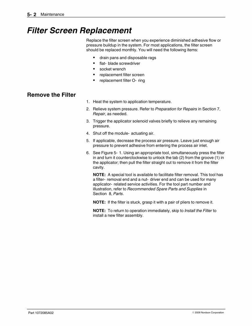
6. See Figure 5- 1. Using an appropriate tool, simultaneously press the filterin and turn it counterclockwise to unlock the tab (2) from the groove (1) inthe applicator; then pull the filter straight out to remove it from the filtercavity.
NOTE: A special tool is available to facilitate filter removal. This tool hasa filter- removal end and a nut- driver end and can be used for manyapplicator- related service activities. For the tool part number andillustration, refer to Recommended Spare Parts and Supplies inSection 8, Parts.
NOTE: If the filter is stuck, grasp it with a pair of pliers to remove it.
NOTE: To return to operation immediately, skip to Install the Filter toinstall a new filter assembly.

Maintenance 5- 3
Part 1072085A02� 2009 Nordson Corporation
1
2
3
4
5
Figure 5- 1 Removing the filter
1. Groove
2. Tab
3. Bung
4. O- ring
5. Screen
Maintenance5- 4
Part 1072085A02 � 2009 Nordson Corporation
Replace the Filter Screen1. See Figure 5- 1. Disassemble the filter.
2. Apply O- ring lubricant to a new O- ring and reassemble the filter.
Install the Filter1. Heat the system to application temperature.
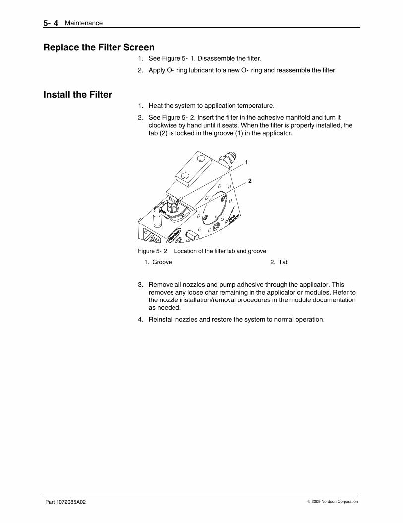
2. See Figure 5- 2. Insert the filter in the adhesive manifold and turn itclockwise by hand until it seats. When the filter is properly installed, thetab (2) is locked in the groove (1) in the applicator.
1
2
Figure 5- 2 Location of the filter tab and groove
1. Groove 2. Tab
3. Remove all nozzles and pump adhesive through the applicator. Thisremoves any loose char remaining in the applicator or modules. Refer tothe nozzle installation/removal procedures in the module documentationas needed.
4. Reinstall nozzles and restore the system to normal operation.

Troubleshooting 6- 1
Part 1072085A02� 2009 Nordson Corporation
Section 6
Troubleshooting
WARNING! Allow only personnel with appropriate training and experience to
operate or service the equipment. The use of untrained or inexperiencedpersonnel to operate or service the equipment can result in injury, including
death, to themselves and others, and damage to the equipment.
IntroductionTroubleshooting begins when the flow of adhesive from the applicator stopsor diminishes unexpectedly or when a control system alerts you of a problemthrough an alarm or visual display. This section covers only the mostcommon problems you may encounter. If you cannot solve a problem withthe information given here, contact your local Nordson representative forhelp.
For additional troubleshooting information, refer to the manuals provided withthe other equipment used in the hot melt system.

Troubleshooting6- 2
Part 1072085A02 � 2009 Nordson Corporation
Applicator Heating Problems
WARNING! Risk of personal injury or death. Allow only qualified personnel to
perform electrical installation, troubleshooting, or repair procedures. Before
performing any electrical procedure, review Section 1, Safety, anddisconnect and lock out electrical power to the system.
Problem Possible Cause Corrective Action
1. Applicator does notheat
System power not on Verify that the system power is turnedon.
Loose electrical connections Verify that all electrical connections(cordsets and cables) are secure.
Broken or missing pins or damagedcordset connectors
Check for broken or missing pins ordamaged connectors at all electricalconnections. Repair or replacedamaged components.
Adhesive or air temperaturesetpoints too low
Adjust the temperature setpoints asnecessary. Refer to the melter ortemperature controller manual.
2. Unstable temperatureor pressure readings
Loose electrical connection Verify that all electrical connections(cordsets and cables) are secure.
Incorrect PID (proportional, integral,derivative) settings or incorrect typeof control system or controller usedto operate applicator
Adjust PID settings as needed. Referto the manual for the control system orcontroller being used. To ensureproper temperature and pressurecontrol, use the Nordson Universalslice controller to operate theapplicator.
Unstable pressure supply toapplicator
Check the melter pressure controlvalve and ensure that there is a stablepressure supply to the applicator.
Continued...

Troubleshooting 6- 3
Part 1072085A02� 2009 Nordson Corporation
Problem Possible Cause Corrective Action
3. Applicator underheatsor overheats
Temperature setpoints too low ortoo high
Adjust the temperature setpoints asnecessary. Refer to the melter ortemperature controller manual.
Failed heater or sensor Check the resistance of the suspectheater or sensor. Refer to WiringDiagrams in Section 9, TechnicalData, for cordset pin diagrams.
To determine what the resistance of aheater should be, use the followingformula: V2 ÷ W= R (whereV=voltage, W=wattage, andR=resistance). Slice applicatorheaters are 500 W.
Sensor not touching bottom of well,reporting incorrect temperature(contd.)
Ensure that all sensors are fullyseated.
Failed heater or sensor The resistance of a 100- ohmplatinum sensor should be 100 ohms.The resistance of a 120- ohm nickelsensor should be 120 ohms.
Replace failed components asnecessary. Refer to Section 7, Repair,for heater and sensor replacementprocedures.
Incorrect PID settings or incorrecttype of control system or controllerused to operate applicator
Adjust PID settings as needed. Referto the manual for the control system orcontroller being used. To ensureproper temperature and pressurecontrol, use the Nordson Universalslice controller to operate theapplicator.

Troubleshooting6- 4
Part 1072085A02 � 2009 Nordson Corporation
Adhesive Output Problems
Problem Possible Cause Corrective Action
1. Adhesive output toolow or too high
Temperature setpoints too low ortoo high
Adjust the temperature setpoints asnecessary. Refer to the melter ortemperature controller manual.
Melter not supplying correctamount of adhesive
Troubleshoot and correct theadhesive supply problem from themelter. The melter should besupplying about 20 percent moreadhesive than the applicator requires.Refer to Supply Pressure Adjustmentin Section 3, Installation.
Blockage in hose- to- applicator orhose- to- melter connection
Check for blockages in theconnections. Check also for a coldconnection. Install insulation aroundany cold connections. If the adhesiveoutput does not improve, install aheated inline filter at the connection.
Clogged filter Replace the filter screen. Refer toFilter Screen Replacement inSection 5, Maintenance.
Blockage in module or nozzle Check for blockage in the module ornozzle.
Contaminated air supply Ensure that the applicator is beingsupplied with dry, regulated,unlubricated air.
Ruptured rupture disk caused byhose blockage or temperatureissue
Check the hose for blockage or atemperature control issue and correctas applicable. Flush the system asneeded.
Replace the rupture disk. Refer toRupture Disk Replacement inSection 7, Repair.
2. No adhesive output Adhesive not at applicationtemperature
Wait for the system to reachapplication temperature.
Temperature setpoints too low ortoo high
Adjust the temperature setpoints asnecessary. Refer to the melter ortemperature controller manual.
Adhesive level in melter low Add adhesive to the melter. Refer tothe melter manual.
Blockage in hose- to- applicator orhose- to- melter connection
Check for blockages in theconnections. Check also for a coldconnection. Install insulation aroundany cold connections. If the adhesiveoutput does not improve, install aheated inline filter at the connection.
Continued...

Troubleshooting 6- 5
Part 1072085A02� 2009 Nordson Corporation
Problem Possible Cause Corrective Action
2. No adhesive output(contd.)
Clogged filter Replace the filter screen. Refer toFilter Screen Replacement inSection 5, Maintenance.
Module stem stuck in closedposition; debris or char preventingstem movement
Replace the module with a new orrebuilt module. Refer to the moduledocumentation.
Module piston seal worn out Replace the module with a new orrebuilt module. Refer to the moduledocumentation.
Adhesive or debris in modulepiston bore
Replace the module with a new orrebuilt module. Refer to the moduledocumentation.
NOTE: To prevent the migration ofadhesive into the air supply, ensurethat there is no adhesive on themanifold face when a module isreplaced.
Failed solenoid valve Check the solenoid valve and replaceas needed. Refer to the moduledocumentation.
Failed or faulty solenoid valvetriggering device
Troubleshoot the triggering device.Refer to the triggering devicedocumentation.
3. Adhesive outputcannot be shut off
Module stem stuck in openposition; debris or char preventingstem movement
Replace the module with a new orrebuilt module. Refer to the moduledocumentation.
Module piston seal worn out Replace the module with a new orrebuilt module. Refer to the moduledocumentation.
Adhesive or debris in modulepiston bore
Replace the module with a new orrebuilt module. Refer to the moduledocumentation.
NOTE: To prevent the migration ofadhesive into the air supply, ensurethat there is no adhesive on themanifold face when a module isreplaced.

Troubleshooting6- 6
Part 1072085A02 � 2009 Nordson Corporation
Adhesive Leakage Problems
CAUTION! Operation of the applicator motor in the wrong direction for
extended periods of time will severely damage the applicator, causing
general O- ring and seal failure and leakage at various points throughout theapplicator. To ensure that the motor is operating in the correct direction, refer
to Motor Rotational Check in Section 7, Repair.
Problem Possible Cause Corrective Action
1. Leaks at variousconnecting points inthe system
Insufficient torque on bolts orscrews
Tighten bolts and screws whereleakage is occurring
Damaged or worn O- rings or seals Replace O- rings or seals as needed.Contact your Nordson representativefor information on complete applicatordisassembly and reassembly.
2. Leaks at pump Damaged or worn pump O- ringsand/or seals
Replace the pump O- rings and seals.Contact your Nordson representativefor information on complete applicatordisassembly and reassembly.
3. Leaks between amodule the manifold
Insufficient torque on modulescrews
Tighten the module screws to3-4 N•m (25-32 in.- lb).
Damaged or worn O- rings on backof module
Replace the O- rings. Refer to themodule documentation.
4. Leaks from bleedholes on modules
Failed O- rings/seals in module(O- rings/seals used beyondexpected life)
Replace the module with a new orrebuilt module. Refer to the moduledocumentation.
System pressure too high Adjust the system pressure.
NOTE: To prevent this condition,regularly check for nozzle clogging.
5. Leaks at nozzle System pressure too high Decrease the system pressure. Referto the melter manual.
Damaged or worn O- ring inmodule seat
Replace the O- ring. Refer to themodule documentation.
6. Leaks at hoseconnection
Loose hose connection Tighten the connection.
Failed hose fitting O- ring Replace the hose fitting O- ring.
7. Leaks at rupture disk Improperly seated rupture disk Reseat the rupture disk or replace it ifthe crush seal is damaged. Refer toRupture Disk Replacement inSection 7, Repair.

Troubleshooting 6- 7
Part 1072085A02� 2009 Nordson Corporation
Pump and Drive Problems
Problem Possible Cause Corrective Action
1. Motor stops or fails tostart
System power not on Verify that the system power is turnedon.
System ready condition notreached
Wait until the system ready conditionis reached.
Loose line speed tachometer wiringconnections
Check the wiring connections.
Failed motor Measure the resistance across themotor windings. If the circuit is open,replace the motor.
Motor overtemperature alarmactivated
Troubleshoot the motor.
Problem in on/off circuit Check for loose wiring or defectiveswitches.
Problem in motor controller Troubleshoot the motor controller.
2. Pump not turning(motor running)
Broken key Replace the key.
Pump binding Contact your Nordson representative.
3. Excessive torque indrive system
Plugged output at one or morepositions
Check the hose for blockage. Checkthe manifold for output.
Adhesive not at operatingtemperature when pump started
Increase temperature setpoints to thenormal settings. Avoid starting thepump at below- normal temperaturesettings.
Pump binding or locking up Replace the pump. Contact yourNordson representative for pumpreplacement assistance as needed.

Troubleshooting6- 8
Part 1072085A02 � 2009 Nordson Corporation
Air Supply Problems
Problem Possible Cause Corrective Action
1. Module- actuating airleaking
Failed piston seal inside module Replace the module with a new orrebuilt module. Refer to the moduledocumentation.
Failed solenoid valve (solenoidvalve used beyond expected life)
Check the solenoid valve and replaceif necessary. Refer to the moduledocumentation.
2. No module- actuatingair
Failed solenoid valve (solenoidvalve used beyond expected life)
Check the solenoid valve and replaceif necessary. Refer to the moduledocumentation.
Failed air pressure regulator orinsufficient air supply to theregulator
Check the regulator and the air supplyto the regulator.
3. No pattern air Failed air pressure regulator orinsufficient air supply to theregulator
Check the regulator and the air supplyto the regulator.
Clogged air passage in nozzle Clean or replace the nozzle. Refer tothe module documentation.
Pattern Control ProblemsRefer to the module documentation.

Repair 7- 1
Part 1072085A02� 2009 Nordson Corporation
Section 7
Repair
WARNING! Allow only personnel with appropriate training and experience to
operate or service the equipment. The use of untrained or inexperiencedpersonnel to operate or service the equipment can result in injury, including
death, to themselves and others, and damage to the equipment.
IntroductionThis section provides selected service procedures for the slice applicator.You may need to perform one or more of these procedures if a componenthas failed or as part of a preventive maintenance program. Follow theseguidelines when performing any service activity:
� Have the required tools, supplies, and replacement parts on hand.
They are listed at the beginning of each service procedure. Refer toSection 8, Parts, for component part numbers.
NOTE: Several special tools are available to facilitate servicing of theslice applicator. Refer to Recommended Spare Parts and Supplies inSection 8, Parts.
� Relieve system pressure and/or disable the applicator as appropriate
before performing any service activity. Refer to Preparation forRepairs in this section.

Location of pressure relief valve
Repair7- 2
Part 1072085A02 � 2009 Nordson Corporation
Preparation for RepairsBefore you can safely proceed with many of the maintenance,troubleshooting, and repair procedures in this manual, you will need todisable the applicator to prevent unwanted restarts or electrical hazards fromoccurring during performance of a procedure.
This procedure includes all the steps necessary to completely disable theapplicator both hydraulically and electrically. It is not necessary to perform allof these steps for some procedures, so at the beginning of each procedurethe preparatory steps recommended by Nordson are noted. Refer to thisprocedure as needed for more detail.
NOTE: Refer to Section 1, Safety, for a complete list of the warningsassociated with Nordson equipment.
1. Disable the applicator pumps by locking out the motor control to preventany unwanted restarts before this procedure is completed.
2. Disable the applicator by locking out the heat control to prevent electricalhazards.
3. Place a drain pan under the pressure relief valve and relieve pressurefrom the applicator by turning the relief valve screw one turncounterclockwise.
4. Place drain pans under the modules and energize the solenoid valves toopen the modules, relieving any residual pressure between the pumpsand modules.
5. When adhesive stops flowing from the modules, stop energizing thesolenoid valves.
6. Shut off the air supplies (module- actuating air and process air) to thesolenoid valves.
7. Disable the power supply to the solenoid valves.
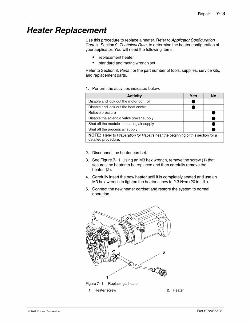
Repair 7- 3
Part 1072085A02� 2009 Nordson Corporation
Heater ReplacementUse this procedure to replace a heater. Refer to Applicator ConfigurationCode in Section 9, Technical Data, to determine the heater configuration ofyour applicator. You will need the following items:
� replacement heater
� standard and metric wrench set
Refer to Section 8, Parts, for the part number of tools, supplies, service kits,and replacement parts.
1. Perform the activities indicated below.
Activity Yes No
Disable and lock out the motor control ����
Disable and lock out the heat control ����
Relieve pressure ����
Disable the solenoid valve power supply ����
Shut off the module- actuating air supply ����
Shut off the process air supply ����
NOTE: Refer to Preparation for Repairs near the beginning of this section for adetailed procedure.
2. Disconnect the heater cordset.
3. See Figure 7- 1. Using an M3 hex wrench, remove the screw (1) thatsecures the heater to be replaced and then carefully remove theheater (2).
4. Carefully insert the new heater until it is completely seated and use anM3 hex wrench to tighten the heater screw to 2.3 N�m (20 in.- lb).
5. Connect the new heater cordset and restore the system to normaloperation.
1
2
Figure 7- 1 Replacing a heater
1. Heater screw 2. Heater

Repair7- 4
Part 1072085A02 � 2009 Nordson Corporation
Sensor ReplacementUse this procedure to replace a temperature sensor. Refer to ApplicatorConfiguration Code in Section 9, Technical Data, to determine the sensorconfiguration of your applicator. You will need the following item:
� replacement sensor
Refer to Section 8, Parts, for the part number of tools, supplies, service kits,and replacement parts.
1. Perform the activities indicated below.
Activity Yes No
Disable and lock out the motor control ����
Disable and lock out the heat control ����
Relieve pressure ����
Disable the solenoid valve power supply ����
Shut off the module- actuating air supply ����
Shut off the process air supply ����
NOTE: Refer to Preparation for Repairs near the beginning of this section for adetailed procedure.
2. Disconnect the sensor cordset.
3. See Figure 7- 2. By hand, turn the thermowell (2) that secures thesensor (1) one- quarter turn counterclockwise and then remove thesensor.
1
2
Figure 7- 2 Fixed- depth sensor components
1. Sensor 2. Thermowell
4. Install the new sensor and secure it with the thermowell.
5. Connect the new sensor cordset and restore the system to normaloperation.

Repair 7- 5
Part 1072085A02� 2009 Nordson Corporation
This page intentionally left blank.

Repair7- 6
Part 1072085A02 � 2009 Nordson Corporation
Pressure Transducer ReplacementUse this procedure to replace a pressure transducer. You will need thefollowing items:
� replacement pressure transducer
� standard and metric wrench set
Refer to Section 8, Parts, for the part number of tools, supplies, service kits,and replacement parts.
1. Perform the activities indicated below.
Activity Yes No
Disable and lock out the motor control ����
Disable and lock out the heat control ����
Relieve pressure ����
Disable the solenoid valve power supply ����
Shut off the module- actuating air supply ����
Shut off the process air supply ����
NOTE: Refer to Preparation for Repairs near the beginning of this section for adetailed procedure.
2. See Figure 7- 3. Using a 2.5- mm hex wrench, remove the pressuretransducer mounting screws (1) and then carefully pull the transducerand crush seal (2) from the end plate or pump, as applicable.
2
1
Figure 7- 3 Removing a pressure transducer
1. Mounting screw 2. Crush seal

Repair 7- 7
Part 1072085A02� 2009 Nordson Corporation
3. Ensure that the crush seal is in place on the replacement transducer.
4. Carefully insert the replacement transducer into the port on the end plateor pump body, as applicable.
5. Align the mounting screw holes, thread the mounting screws into place,and tighten the screws to 1.7 N�m (15 in.- lb).
6. Restore the system to normal operation.

Repair7- 8
Part 1072085A02 � 2009 Nordson Corporation
Immersion Sensor ReplacementUse this procedure to replace an immersion sensor. Refer to ApplicatorConfiguration Code in Section 9, Technical Data, to determine if this sensoris present on your applicator. You will need the following items:
� replacement immersion sensor
� standard and metric wrench set
Refer to Section 8, Parts, for the part number of tools, supplies, service kits,and replacement parts.
1. Perform the activities indicated below.
Activity Yes No
Disable and lock out the motor control ����
Disable and lock out the heat control
NOTE: Verity with a qualified electrician that leaving theheat control on for this procedure will not create anelectrical hazard when the sensor is disconnected.
����
Relieve pressure ����
Disable the solenoid valve power supply ����
Shut off the module- actuating air supply ����
Shut off the process air supply ����
NOTE: Refer to Preparation for Repairs near the beginning of this section for adetailed procedure.
2. Disconnect the sensor cordset.
3. See Figure 7- 4. Using a hex wrench, remove the sensor (1) byunscrewing the nut (2) that secures the sensor. The ferrule (3) will beretained on the sensor.

Repair 7- 9
Part 1072085A02� 2009 Nordson Corporation
1
3 2
Figure 7- 4 Immersion sensor components
1. Immersion sensor
2. Nut
3. Ferrule
4. Slide the new nut and ferrule from the service kit onto the new sensor.
5. Insert the new sensor in the applicator end plate and push the sensor inuntil the locating ring on the sensor is flush with the exterior face of theretaining nut.
6. Use a hex wrench to tighten the nut and ferrule on the fitting to 2.8 N�m(25 in.- lb).
7. Connect the new sensor cordset and restore the system to normaloperation.
8. If leakage occurs, loosen and retighten the retaining nut. If leakagecontinues, install a new immersion sensor.
NOTE: Because the ferrule is pressed onto the sensor body when it isinitially tightened, Nordson Corporation recommends installing a newsensor and ferrule rather than trying to replace a damaged ferrule.
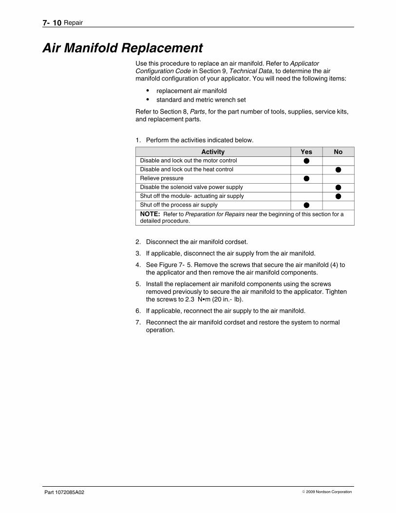
Repair7- 10
Part 1072085A02 � 2009 Nordson Corporation
Air Manifold ReplacementUse this procedure to replace an air manifold. Refer to ApplicatorConfiguration Code in Section 9, Technical Data, to determine the airmanifold configuration of your applicator. You will need the following items:
� replacement air manifold
� standard and metric wrench set
Refer to Section 8, Parts, for the part number of tools, supplies, service kits,and replacement parts.
1. Perform the activities indicated below.
Activity Yes No
Disable and lock out the motor control ����
Disable and lock out the heat control ����
Relieve pressure ����
Disable the solenoid valve power supply ����
Shut off the module- actuating air supply ����
Shut off the process air supply ����
NOTE: Refer to Preparation for Repairs near the beginning of this section for adetailed procedure.
2. Disconnect the air manifold cordset.
3. If applicable, disconnect the air supply from the air manifold.
4. See Figure 7- 5. Remove the screws that secure the air manifold (4) tothe applicator and then remove the air manifold components.
5. Install the replacement air manifold components using the screwsremoved previously to secure the air manifold to the applicator. Tightenthe screws to 2.3 N�m (20 in.- lb).
6. If applicable, reconnect the air supply to the air manifold.
7. Reconnect the air manifold cordset and restore the system to normaloperation.

Repair 7- 11
Part 1072085A02� 2009 Nordson Corporation
1
2
3
4
Figure 7- 5 Air manifold components
1. Mounting screw seal
2. Gasket
3. Side seal
4. Air manifold
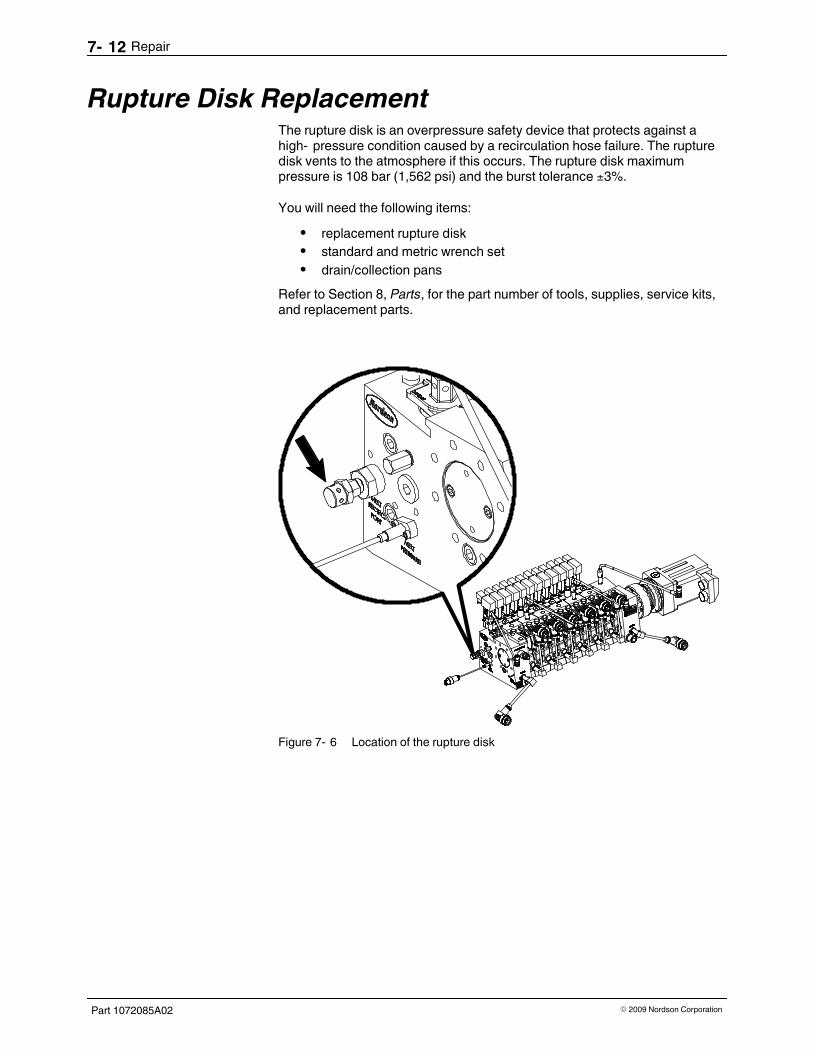
Repair7- 12
Part 1072085A02 � 2009 Nordson Corporation
Rupture Disk ReplacementThe rupture disk is an overpressure safety device that protects against ahigh- pressure condition caused by a recirculation hose failure. The rupturedisk vents to the atmosphere if this occurs. The rupture disk maximumpressure is 108 bar (1,562 psi) and the burst tolerance ±3%.
You will need the following items:
� replacement rupture disk
� standard and metric wrench set
� drain/collection pans
Refer to Section 8, Parts, for the part number of tools, supplies, service kits,and replacement parts.
Figure 7- 6 Location of the rupture disk

Repair 7- 13
Part 1072085A02� 2009 Nordson Corporation
1. Perform the activities indicated below.
Activity Yes No
Disable and lock out the motor control ����
Disable and lock out the heat control ����
Relieve pressure ����
Disable the solenoid valve power supply ����
Shut off the module- actuating air supply ����
Shut off the process air supply ����
NOTE: Refer to Preparation for Repairs near the beginning of this section for adetailed procedure.
2. Actuate the modules momentarily to ensure that the system pressure isfully relieved.
3. See Figure 7- 7. Using a 7/16- in. wrench, loosen and remove the rupturedisk and its components.
4. Ensuring that the crush seal is oriented as shown in Figure 7- 7, install anew rupture disk. Tighten the rupture disk to 5.6 N�m (50 in.- lb).
5. Restore the system to normal operation.
1
2
Figure 7- 7 Replacing a rupture disk
1. Rupture disk 2. Correct orientation for crushseal

Repair7- 14
Part 1072085A02 � 2009 Nordson Corporation
Motor Rotational CheckFor proper operation, the applicator motor must be rotating in the correctdirection. Operation of the applicator when the rotational direction is incorrectwill severly damage the applicator.
The rotational direction of the motor should be checked:
� before operating the system for the first time
� after any changes have been made to the system (such as replacing
the reducer or replacing a motor drive inside the controller)
1. Before performing this procedure, ensure that:
� the applicator has been properly installed according to Section 3,
Installation
� all components in the system are heated to application temperature
� adhesive is flowing through the system
2. Perform the activities indicated below.
Activity Yes No
Disable and lock out the motor control ����
Disable and lock out the heat control ����
Relieve pressure ����
Disable the solenoid valve power supply ����
Shut off the module- actuating air supply ����
Shut off the process air supply ����
NOTE: Refer to Preparation for Repairs near the beginning of this section fordetailed procedures.
3. See Figure 7- 8. If the applicator has an inline Servo drive, remove thedrive access plug (1).
NOTE: The rotation can be identified on all other drive configurationswithout removing the drive access plug. Refer to Applicator ConfigurationCode in Section 9, Technical Data, to determine the drive configuration ofyour applicator.
4. Place the applicator pump in the manual mode and set the pump rpmto 2 (very slow).
5. Enable the motor control and start the applicator motor.

Repair 7- 15
Part 1072085A02� 2009 Nordson Corporation
32
1
Figure 7- 8 Correct rotational direction of motor for an inline drive (left) and a right- angle drive (right)
1. Drive access plug 2. Drive rotation arrow on left side ofapplicator (counterclockwise)
3. Drive rotation arrow on rightside of applicator (clockwise)
6. See Figure 7- 8. Verify that the pump shaft is rotating in the directionindicated by the DRIVE ROTATION arrows engraved on the applicatorend plates (2, 3).
7. If the motor is not rotating in the correct direction:
a. Stop the motor.
b. Reverse the analog wires connected to the motor drive input/outputinterface cards inside the motor controller. Refer to the motorcontroller manual or to the electrical schematic for the wire numbers.
c. Repeat steps 5-6 to ensure that the motor is rotating in the correctdirection.
8. When you have verified that the motor is rotating in the correct direction,restore the system to normal operation.

Repair7- 16
Part 1072085A02 � 2009 Nordson Corporation
Applicator RebuildComplete disassembly and reassembly (rebuilding) of a Universal sliceapplicator requires special equipment and procedures. To rebuild a sliceapplicator (for applicator cleaning and lapping, O- ring and seal replacement,applicator reconfiguration, etc.), order an applicator rebuild kit and theservice tool kit. The rebuild kit includes instructions for rebuilding anapplicator. Refer to Section 8, Parts, for the service kit and instruction sheetpart numbers. Contact your Nordson representative for additional informationas needed.

Parts 8‐1
Part 1072085A02� 2009 Nordson Corporation
Section 8Parts
Using the Illustrated Parts ListsTo order parts, call the Nordson Customer Service Center or your localNordson representative. Use these five‐column parts lists, and theaccompanying illustrations, to describe and locate parts correctly. Thefollowing chart provides guidance for reading the parts lists.
The number in the Item column corresponds to the circled item number in theparts list illustration. A dash in this column indicates that the item is anassembly.
The number in the Part column is the Nordson part number you canuse to order the part. A series of dashes indicates that the part is notsaleable. In this case, you must order either the assembly in whichthe part is used or a service kit that includes the part.
The Description column describes the part and sometimesincludes dimensions or specifications.
The Note column contains letters that refer to notes at thebottom of the parts list. These notes provide importantinformation about the part.
The Quantity column tells you how many of the part isused to manufacture the assembly shown in the partslist illustration. A dash or AR in this column indicates thatthe amount of the item required in the assembly is notquantifiable.
Item Part Description Quantity Note— 0000000 Assembly A —1 000000 � Part of assembly A 2 A2 ‐ ‐ ‐ ‐ ‐ ‐ � � Part of item 1 13 0000000 � � �
Part of item 2AR
NS 000000 � � � �
Part of item 32
NOTE A: Important information about item 1AR: As RequiredNS: Not Shown
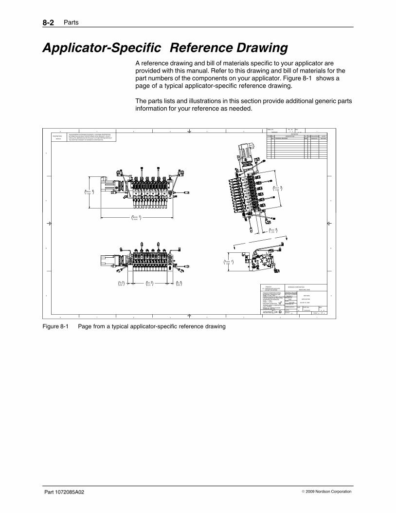
Parts8‐2
Part 1072085A02 � 2009 Nordson Corporation
Applicator‐Specific Reference DrawingA reference drawing and bill of materials specific to your applicator areprovided with this manual. Refer to this drawing and bill of materials for thepart numbers of the components on your applicator. Figure 8‐1 shows apage of a typical applicator‐specific reference drawing.
The parts lists and illustrations in this section provide additional generic partsinformation for your reference as needed.
8 7
A
6 5 4
B
C
NORDSON CORPORATION
UNITS:THIRD ANGLE
3
PROJECTION
2
SCALE: SHEET
ASME Y14.5M - 1994
FOR INTERRELATED FEATURES.
INTERPRET DRAWINGS PER
X.XXX = ±.010MACHINED SURFACES
CORNERS .005/.030.
FULL THREAD.BREAK ALL INSIDE/OUTSIDE
X.XX = ±.030
THREAD LENGTH DIMENSIONS ARE
PERFECT FORM AT MMC REQUIRED
ENGLISH
EXCEPT AS NOTEDALL DIMENSIONS IN INCHES
.
.
.
.
.
.
APPROVED BY:
ORIGINAL RELEASERELEASE NUMBER:
CHECKED BY:
DATE:
DRAWN BY:
PART NO.SIZE
1
OF
REV
A
B
C
D
8 7 6 5 4
RELEASE NO.ZONE
DWG. NO.3
REVISIONSREV DESCRIPTION
SH OF REV
BY CHK DATE
1
THIS DRAWING IS NORDSON PROPERTY, CONTAINS PROPRIETARY
THE WRITTEN CONSENT OF NORDSON CORPORATION.
INFORMATION AND MUST BE RETURNED UPON REQUEST. DO NOTCIRCULATE, REPRODUCE OR DIVULGE TO OTHER PARTIES WITHOUT
PROPRIETARY
NOTICE
XXXXXXX A 01
NS202377
1:3 2 2
XXXXXXX A 012 2
REF DWG.
APPLICATOR
G3-300-12, OSR
RAB
06/14/06
UNLESS OTHERWISE NOTED:
125
STANDARD TOLERANCES:
D
WESTLAKE, OHIO
A01 ORIGINAL RELEASE RAB NS202377 06/14/06
6.490164.84
A
A
1.96950
11.811300
1.96950
25.031635.80
11.026280.05
12.686322.22
1.37534.93
Figure 8‐1 Page from a typical applicator‐specific reference drawing

Parts 8‐3
Part 1072085A02� 2009 Nordson Corporation
Service KitsThe following service kits contain the parts needed to perform a specificmaintenance or repair activity.
Part Description Note1095522 KIT, REBUILD, SLICE, O‐RING, END PLATES, G3 A1095523 KIT, REBUILD, SLICE, O‐RING, PER SLICE, G3 B1095427 � Instructions, Universal slice applicator rebuild kit, G3 C
NOTE A: Order this kit to replace all the seals and O‐rings on an applicator.B: Order this kit to replace the seals and O‐rings on only one manifold slice.C: This instruction sheet is available on emanuals.nordson.com and includes the slice applicator rebuild kit
part numbers. Contact your Nordson representative for assistance as needed.
Tools and SuppliesTo facilitate maintenance and repair activities and to achieve the bestmaintenance/repair results, the following tools and supplies arerecommended.
Part Description Note1095524 KIT, SERVICE TOOLS, SLICE, G31058544 TOOL, UNIV, FILTER REMOVAL PLUS, UA900223 LUBRICANT, O RING, PARKER, 4 OZ A900344 LUBRICANT, NEVER SEEZ, 8 OZ CAN B902504 TAPE, PTFE, ROLL, 1/2” x 520 LG C
NOTE A: Used to lubricate O‐rings and seals.B: Used to lubricate all straight‐thread fittings.C: Used to seal pipe threads.

Parts8‐4
Part 1072085A02 � 2009 Nordson Corporation
Slice Applicator AssembliesSee Figure 8‐2 .
NOTE: Parts lists for smaller assemblies, such as sensors, transducers,cables, etc., are provided later in this section.
Item Part Description Quantity Note— ‐ ‐ ‐ ‐ ‐ ‐
‐Assembly, slice applicator — A
1 ‐ ‐ ‐ ‐ ‐ ‐‐
� Assembly, end plate 2 A, B
2 ‐ ‐ ‐ ‐ ‐ ‐‐
� Assembly, middle plate AR A, C
3 ‐ ‐ ‐ ‐ ‐ ‐‐
� Assembly, air manifold AR A, D
4 ‐ ‐ ‐ ‐ ‐ ‐‐
� Assembly, drive 1 A, E
5 ‐ ‐ ‐ ‐ ‐ ‐‐
� Assembly, pump AR A, F
6 ‐ ‐ ‐ ‐ ‐ ‐‐
� Shaft, pump 1 A, G
7 ‐ ‐ ‐ ‐ ‐ ‐‐
� Module, dispensing AR A, H
NOTE A: The part number of this item varies depending on the configuration of the applicator. Refer to ApplicatorConfiguration Code in Section 9, Technical Data, to determine the configuration of your applicator.
B: Refer to End Plate Assembly Parts later in this section.C: Refer to Middle Plate Assembly Parts later in this section.D: Refer to Air Manifold Assembly Parts later in this section.E: Refer to Drive Assembly Parts later in this section.F: Refer to Pump Assembly Parts later in this section.G: Refer to Pump Shafts later in this section.H: Refer to the module documentation supplied with the applicator.
AR: As RequiredNS: Not Shown

Parts 8‐5
Part 1072085A02� 2009 Nordson Corporation
4
5
6
1
13
2
7
Figure 8‐2 Slice applicator assemblies

Parts8‐6
Part 1072085A02 � 2009 Nordson Corporation
End Plate Assembly PartsYour applicator may have one of two end plate assemblies: one for left‐sideoperation (OSL) or one for right‐side operation (OSR). Refer to the correctparts list for your applicator.
OSL End PlateSee Figure 8‐3 .
Item Part Description Quantity Note— ‐ ‐ ‐ ‐ ‐ ‐ ASSY,END PLATE,EXT. RECIRC.,G3,OSL — A1 ‐ ‐ ‐ ‐ ‐ ‐ � PLATE, RIGHT END, 50MM 12 ‐ ‐ ‐ ‐ ‐ ‐ � BLOCK,END PLATE,50MM,G3 SLICE,LH 13 ‐ ‐ ‐ ‐ ‐ ‐ � PLATE, DRIVE SHAFT COVER 14 ‐ ‐ ‐ ‐ ‐ ‐ � PLATE, DRIVE SEAL RETAINING 15 1049206 � FILTER,ASSEMBLY,UA,I/O 1 B6 1065512 � SEAL, 5/8 ID, ROTARY 18 1064747 � CARTRIDGE, HEATER, 3/8 DIA, 500 WATT 29 ‐ ‐ ‐ ‐ ‐ ‐ � BUSHING, 5/8 ID , DRIVE ALIGNMENT 1
11 ‐ ‐ ‐ ‐ ‐ ‐ � SCR,SKT,M4X16,ZN 412 ‐ ‐ ‐ ‐ ‐ ‐ � SCR,SKT,M8X55,ZN 315 1003265 � THERMOWELL,1/8 NPT (SMALL) 216 ‐ ‐ ‐ ‐ ‐ ‐ � SCR,SKT,M4X10MM,BL 217 181862 � PLATE,CF,WARNING,CE,HOT 218 181863 � PLATE,CF,WARNING,CE,ELEC,SHOCK 219 ‐ ‐ ‐ ‐ ‐ ‐ � SCR,DRIVE,RD,2X .187,ZN 1020 940181 � O RING,VITON,.739ID X .070W,BR,10418 121 940223 � O RING,VITON,.989ID X .070W,BR, 10422 122 940161 � O RING,VITON,.614ID X .070W,BR, 10416 123 940133 � O RING,VITON,.426ID X .070W,BR,10413 124 1003271 � NDV A14328,SEAL MODULAR PUMP‐DFMU 125 1064761 � SEAL, HAM SIDE, SHARED AIR PORT 126 1057954 � TIP, DRAIN VALVE, UNIVERSAL 127 ‐ ‐ ‐ ‐ ‐ ‐ � BALL,440SSTL, .250,100 128 1066296 � SEAL, DIVERTER PLATE SIDE 129 ‐ ‐ ‐ ‐ ‐ ‐ � PLATE, HEAT ISOLATOR, MOUNTING 230 ‐ ‐ ‐ ‐ ‐ ‐ � PLATE,INFORMATION,G3 SLICE,CE 132 1069892 � ADAPTOR, RUPTURE DISK, G3 SLICE 133 940141 � O RING,VITON,.489ID X .070W,BR,10414 134 1003262 � NDV B15559,KIT,RUPTURE DISK‐DFMU 135 ‐ ‐ ‐ ‐ ‐ ‐ � RETAINING RING,SPIROL, .50 DIA 136 413261 � SCREW PLUG G 1/4 2
NOTE A: A service kit is available to convert an applicator from external recirculation to internal recirculation. Referto External‐to‐Internal Conversion Kit Parts later in this section.
B: Refer to Filter Assembly Parts later in this section.

Parts 8‐7
Part 1072085A02� 2009 Nordson Corporation
411 6 9 12 1 16
8
15
25
24
21
2223
168
5
15
28
2
29
29
3
1930
27 26 35
19
18
191734 32 33
36
2
1
20
REAR ISO EXPLODED
FRONT ISO EXPLODED
Figure 8‐3 OSL end plate parts

Parts8‐8
Part 1072085A02 � 2009 Nordson Corporation
OSR End PlateSee Figure 8‐4 .
Item Part Description Quantity Note— ‐ ‐ ‐ ‐ ‐ ‐ ASSY,END PLATE,EXT. RECIRC.,G3,OSR — A1 ‐ ‐ ‐ ‐ ‐ ‐ � BLOCK,END PLATE,W/FILT&RECIR,G3
SLICE,RH1
2 ‐ ‐ ‐ ‐ ‐ ‐ � BLOCK,END PLATE, G3 SLICE,LH 13 ‐ ‐ ‐ ‐ ‐ ‐ � PLATE, DRIVE SHAFT COVER 14 ‐ ‐ ‐ ‐ ‐ ‐ � PLATE, DRIVE SEAL RETAINING 15 1049206 � FILTER,ASSEMBLY,UA,I/O 1 B6 1065512 � SEAL, 5/8 ID, ROTARY 18 1064747 � CARTRIDGE, HEATER, 3/8 DIA, 500 WATT 2
10 ‐ ‐ ‐ ‐ ‐ ‐ � BUSHING, 5/8 ID , DRIVE ALIGNMENT 111 ‐ ‐ ‐ ‐ ‐ ‐ � SCR,SKT,M4X16,ZN 412 ‐ ‐ ‐ ‐ ‐ ‐ � SCR,HEX,CAP,M8X60,BL 315 1003265 � THERMOWELL,1/8 NPT (SMALL) 216 ‐ ‐ ‐ ‐ ‐ ‐ � SCR,SKT,M4X10MM,BL 217 181862 � PLATE,CF,WARNING,CE,HOT 218 181863 � PLATE,CF,WARNING,CE,ELEC,SHOCK 219 ‐ ‐ ‐ ‐ ‐ ‐ � SCR,DRIVE,RD,2X .187,ZN 1020 940181 � O RING,VITON,.739ID X .070W,BR,10418 121 940161 � O RING,VITON,.614ID X .070W,BR, 10416 122 940133 � O RING,VITON,.426ID X .070W,BR,10413 123 1003271 � NDV A14328,SEAL MODULAR PUMP‐DFMU 124 1064761 � SEAL, HAM SIDE, SHARED AIR PORT 125 1057954 � TIP, DRAIN VALVE, UNIVERSAL 126 ‐ ‐ ‐ ‐ ‐ ‐ � BALL,440SSTL, .250,100 127 1066296 � SEAL, DIVERTER PLATE SIDE 128 ‐ ‐ ‐ ‐ ‐ ‐ � PLATE, HEAT ISOLATOR, MOUNTING 229 ‐ ‐ ‐ ‐ ‐ ‐ � PLATE,INFORMATION,G3 SLICE,CE 131 1069892 � ADAPTOR, RUPTURE DISK, G3 SLICE 132 940141 � O RING,VITON,.489ID X .070W,BR,10414 133 1003262 � NDV B15559,KIT,RUPTURE DISK‐DFMU 134 ‐ ‐ ‐ ‐ ‐ ‐ � RETAINING RING,SPIROL, .50 DIA 135 ‐ ‐ ‐ ‐ ‐ ‐ � SCREW PLUG G 1/4 237 940223 � O RING,VITON,.989ID X .070W,BR, 10422 1
NOTE A: A service kit is available to convert an applicator from external recirculation to internal recirculation. Referto External‐to‐Internal Conversion Kit Parts later in this section.
B: Refer to Filter Assembly Parts later in this section.

Parts 8‐9
Part 1072085A02� 2009 Nordson Corporation
2
28
8
8
15
155
11 4
26 25 34
19
18
17
19
1
16
16
33
31
32
12
10
6
411
1929
16 824
23
22
21
11 3 2012 35816
3727
FRONT ISO EXPLODED
REAR ISO EXPLODED
Figure 8‐4 OSR end plate parts

Parts8‐10
Part 1072085A02 � 2009 Nordson Corporation
External‐to‐Internal Conversion Kit PartsUse these kits to convert an applicator from external recirculation to internalrecirculation. External recirculation is recommended for intermittentapplications. Internal recirculation is recommended for continuousapplications.
OSR Recirculation Plate AssemblySee Figure 8‐5 . Refer to the instructions in Section 3, Installation, and to theinstructions and illustrations provided on the applicator‐specific referencedrawing to make the conversion.
Item Part Description Quantity Note— 1091387 KIT,RECIRC PLATE ASSY, OSR —1 ‐ ‐ ‐ ‐ ‐ ‐ � RECIRCULATION PLATE,G3 SLICE,OSR 12 940303 � O RING,VITON, 1.625X1.750X.063,10430 13 ‐ ‐ ‐ ‐ ‐ ‐ � SCR,SKT,M5 X 0.8 X 12,ZN. 4
2
1
3
NOTES:1. USE ANTI‐SEIZE ON FASTENERS (M6 SHCS)2. TIGHTEN M6 SCREWS TO 110 IN/LBS OF TORQUE3. ENSURE ALL COMPONENTS ARE CLEAN AND FREE FROM DEBRIS PRIOR TO ASSEMBLY4. USE PRECAUTION NOT TO DAMAGE O-RING SEALS DURING INSTALLATION
Figure 8‐5 OSR recirculation plate assembly parts

Parts 8‐11
Part 1072085A02� 2009 Nordson Corporation
OSL Recirculation Plate AssemblySee Figure 8‐6 . Refer to the instructions in Section 3, Installation, and to theinstructions and illustrations provided on the applicator‐specific referencedrawing to make the conversion.
Item Part Description Quantity Note— 1091390 KIT,RECIRC PLATE ASSY, OSL —1 ‐ ‐ ‐ ‐ ‐ ‐ � RECIRCULATION PLATE,G3 SLICE 12 940342 � O‐RING,VITON,2.114 ID X .070W,BR 13 ‐ ‐ ‐ ‐ ‐ ‐ � SCR,SKT,M6X12,ZN 4
2 13
NOTES:1. USE ANTI‐SEIZE ON FASTENERS (M6 SHCS)2. TIGHTEN M6 SCREWS TO 110 IN/LBS OF TORQUE3. ENSURE ALL COMPONENTS ARE CLEAN AND FREE FROM DEBRIS PRIOR TO ASSEMBLY4. USE PRECAUTION NOT TO DAMAGE O-RING SEALS DURING INSTALLATION
Figure 8‐6 OSL recirculation plate assembly parts

Parts8‐12
Part 1072085A02 � 2009 Nordson Corporation
Middle Plate Assembly PartsSee Figure 8‐7 .
Item Part Description Quantity Note— ‐ ‐ ‐ ‐ ‐ ‐ � ASSY, G3 MIDDLE PLATE, #1, 50MM — A— ‐ ‐ ‐ ‐ ‐ ‐ � ASSY, G3 MIDDLE PLATE, #2, 50MM — A1 1064748 � PLATE, MIDDLE SLICE #1, 50MM 1
NS 1064749 � PLATE, MIDDLE SLICE #2, 50MM 12 1064750 � BLOCK, CONTROL AIR INPUT 13 ‐ ‐ ‐ ‐ ‐ ‐ � SCR,SKT,M5X22,BL 25 1065300 � CLAMP, G3 PUMP MOUNTING 26 ‐ ‐ ‐ ‐ ‐ ‐ � SCR,HEX,CAP,M8X20,BL 27 1064747 � CARTRIDGE, HEATER, 3/8 DIA, 500 WATT 18 940133 � O RING,VITON,.426ID X .070W,BR,10413 19 940161 � O RING,VITON,.614ID X .070W,BR, 10416 1
10 940181 � O RING,VITON,.739ID X .070W,BR,10418 111 ‐ ‐ ‐ ‐ ‐ ‐ � SCR,SKT,M8X55,ZN 312 ‐ ‐ ‐ ‐ ‐ ‐ � SCR,SKT,M4X16,ZN 1
NOTE A: The part number of this item varies depending on the configuration of the applicator. Each middle plateaccommodates two diverter plates, which may be configured as needed to achieve the desiredapplication. Refer to Adhesive Diverter Plates later in this section for available diverter plates.
NS: Not Shown
67
12
9
10
11
5
23
8
1
Figure 8‐7 Middle plate parts

Parts 8‐13
Part 1072085A02� 2009 Nordson Corporation
Air Manifold Assembly PartsSee Figure 8‐8 . If your applicator uses process air, it may have one of twotypes of air manifold assembly: shared control or independent control.
Item Part Description Quantity Note— 1077650 ASSY, HAM, SHARED AIR CNTRL — A, B— 1071739 ASSY, HAM, INDEPENDENT CNTRL — A1 ‐ ‐ ‐ ‐ ‐ ‐
‐� BLOCK, HAM, SHARED AIR CONTROL 1
2 ‐ ‐ ‐ ‐ ‐ ‐‐
� CAPSCRM,Socket Head,M5,25mm, Steel,ZincPlt
2
3 1064761 � SEAL, HAM SIDE, SHARED AIR PORT 14 1064759 � GASKET, HAM SEAL 15 1065965 � SEAL, HAM MOUNTING, SCREW 26 466561 � PLUG‐TYPE THREAD‐IN FTG.
‐D08‐G1/8‐00001
NOTE A: Refer to Applicator Configuration Code in Section 9, Technical Data, to determine the air manifoldconfiguration of your applicator.
B: Refer to Air Input Fittings for available shared process air input fittings.
5
4
1
3
2 6
5
4
1
3
2
Figure 8‐8 Shared air manifold (left) and independent air manifold (right) parts

Parts8‐14
Part 1072085A02 � 2009 Nordson Corporation
Drive Assembly PartsYour applicator may have one of several drive assembly configurations:MPL, Lenze, or AC; inline or right‐angle. Refer to the correct parts list foryour applicator.
MPL Inline DriveSee Figure 8‐9 .
Item Part Description Quantity Note— 1071717 ASSY,SERVO DRIVE,10:1,INLINE,MPL —1 ‐ ‐ ‐ ‐ ‐ ‐ � ASSY,BLOCK,SERVO DRIVE, HEAT
ISOLATION, G31
2 1064737 � REDUCER, SERVO, GEAR, 10:1, INLINE 13 1064958 � MOTOR,SERVO, MPL,0.73 KW (1.0HP) 14 1064739 � ADAPTOR, DRIVE SHAFT, 3/8 HEX 15 ‐ ‐ ‐ ‐ ‐ ‐ � SCR,SKT,M6X30,BL 46 ‐ ‐ ‐ ‐ ‐ ‐ � SCR,SKT,M5X14,BL 87 ‐ ‐ ‐ ‐ ‐ ‐ � SCR,SKT,M6X20,BL 48 ‐ ‐ ‐ ‐ ‐ ‐ � WASHER,LK,M,SPT,M4,STL,ZN 49 ‐ ‐ ‐ ‐ ‐ ‐ � SCR,HEX,CAP,M4 X.7‐6G X12 4
10 1069826 � PLUG, SEAL, TP04 GEAR REDUCER 1
7
82
3
5
6
4
9
1
10
Figure 8‐9 MPL inline drive parts

Parts 8‐15
Part 1072085A02� 2009 Nordson Corporation
MPL Right‐Angle DriveSee Figure 8‐10 .
Item Part Description Quantity Note— 1074623 ASSY, SERVO DRIVE, 10:1, 90 DEG,MPL —1 ‐ ‐ ‐ ‐ ‐ ‐
‐� ASSY,BLOCK,SERVO DRIVE,HEAT
ISOLATION, G31
2 1070568 � REDUCER, SERVO, GEAR, 10:1, 90 DEGREE 13 1064958 � MOTOR,SERVO, MPL,0.73 KW (1.0HP) 14 1064739 � ADAPTOR, DRIVE SHAFT, 3/8 HEX 15 ‐ ‐ ‐ ‐ ‐ ‐
‐� SCR,SKT,M6X30,BL 4
6 ‐ ‐ ‐ ‐ ‐ ‐‐
� SCR,HEX,CAP,M5X14,BL 8
7 ‐ ‐ ‐ ‐ ‐ ‐‐
� SCR,SKT,M6X20,BL 4
8 ‐ ‐ ‐ ‐ ‐ ‐‐
� WASHER,LK,M,SPT,M4,STL,ZN 4
9 ‐ ‐ ‐ ‐ ‐ ‐‐
� SCR,HEX,CAP,M4 X.7‐6G X12 4
10 1069826 � PLUG, SEAL, TP04 GEAR REDUCER 1
7
10
2
4
1
6
3
8
9
5
Figure 8‐10 MPL right‐angle drive parts

Parts8‐16
Part 1072085A02 � 2009 Nordson Corporation
Lenze Inline DriveSee Figure 8‐11 .
Item Part Description Quantity Note— 1079195 ASSY, SERVO DRIVE, 10:1, IN‐LINE, LENZE —1 ‐ ‐ ‐ ‐ ‐ ‐
‐� ASSY,BLOCK,SERVO DRIVE,HEAT
ISOLATION,G31
2 1079170 � REDUCER,SERVO,GEAR,10:1,IN‐LINE,LENZE
1
3 1055615 � MOTOR,SERVO,APPLICATOR,LZ DRIVE 14 1064739 � ADAPTOR, DRIVE SHAFT, 3/8 HEX 15 ‐ ‐ ‐ ‐ ‐ ‐
‐� SCR,SKT,M6X30,BL 4
6 ‐ ‐ ‐ ‐ ‐ ‐‐
� SCR,HEX,CAP,M5X14,BL 8
7 ‐ ‐ ‐ ‐ ‐ ‐‐
� SCR,SKT,M6X20,BL 4
8 ‐ ‐ ‐ ‐ ‐ ‐‐
� WASHER,LK,M,SPT,M4,STL,ZN 4
9 ‐ ‐ ‐ ‐ ‐ ‐‐
� SCR,HEX,CAP,M4 X.7‐6G X12 4
10 1069826 � PLUG, SEAL, TP04 GEAR REDUCER 1
2
7
3
154
6
5
14
17
1
Figure 8‐11 Lenze inline drive parts
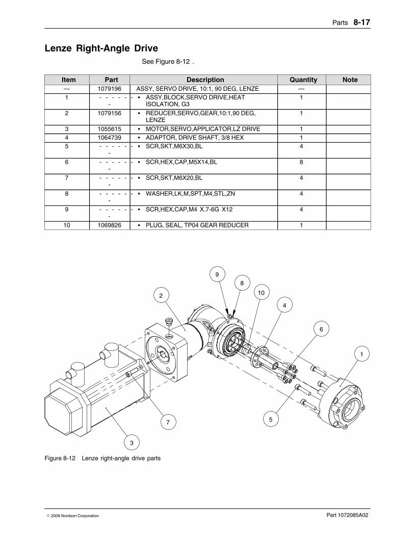
Parts 8‐17
Part 1072085A02� 2009 Nordson Corporation
Lenze Right‐Angle DriveSee Figure 8‐12 .
Item Part Description Quantity Note— 1079196 ASSY, SERVO DRIVE, 10:1, 90 DEG, LENZE —1 ‐ ‐ ‐ ‐ ‐ ‐
‐� ASSY,BLOCK,SERVO DRIVE,HEAT
ISOLATION, G31
2 1079156 � REDUCER,SERVO,GEAR,10:1,90 DEG,LENZE
1
3 1055615 � MOTOR,SERVO,APPLICATOR,LZ DRIVE 14 1064739 � ADAPTOR, DRIVE SHAFT, 3/8 HEX 15 ‐ ‐ ‐ ‐ ‐ ‐
‐� SCR,SKT,M6X30,BL 4
6 ‐ ‐ ‐ ‐ ‐ ‐‐
� SCR,HEX,CAP,M5X14,BL 8
7 ‐ ‐ ‐ ‐ ‐ ‐‐
� SCR,SKT,M6X20,BL 4
8 ‐ ‐ ‐ ‐ ‐ ‐‐
� WASHER,LK,M,SPT,M4,STL,ZN 4
9 ‐ ‐ ‐ ‐ ‐ ‐‐
� SCR,HEX,CAP,M4 X.7‐6G X12 4
10 1069826 � PLUG, SEAL, TP04 GEAR REDUCER 1
1
6
5
10
4
3
7
8
2
9
Figure 8‐12 Lenze right‐angle drive parts

Parts8‐18
Part 1072085A02 � 2009 Nordson Corporation
AC Inline DriveSee Figure 8‐13 .
Item Part Description Quantity Note— 1082978 ASSY, AC DRIVE, 19:1, IN‐LINE —1 1081978 � MOTOR,BS03‐34V/D06LA4‐TOF‐ST/UL‐S
P,.25KW1
2 ‐ ‐ ‐ ‐ ‐ ‐ � ASSY,HEAT ISOLATOR,A/C DRIVE,G3 13 1082976 � ADAPTOR, AC DRIVE SHAFT, 3/8 HEX,
IN‐LINE1
4 1083032 � SEAL,END,G3, AC IN‐LINE DRIVE 15 ‐ ‐ ‐ ‐ ‐ ‐ � SCR,SKT,M6X30,BL 46 ‐ ‐ ‐ ‐ ‐ ‐ � WASHER,LK,M,SPT,M6,STL,ZN 47 ‐ ‐ ‐ ‐ ‐ ‐ � SCR,HEX,CAP,M6X20,ZN 4
4
67
2
5
3
1
Figure 8‐13 AC Inline drive parts

Parts 8‐19
Part 1072085A02� 2009 Nordson Corporation
AC Right‐Angle DriveSee Figure 8‐14 .
Item Part Description Quantity Note— 1082030 AC DRIVE, 19:1, 90 DEGREE —1 1081978 � MOTOR,BS03‐34V/D06LA4‐TOF‐ST/UL‐S
P,.25KW1
2 ‐ ‐ ‐ ‐ ‐ ‐ � ASSY,HEAT ISOLATOR,A/C DRIVE,G3 13 1083150 � ADAPTOR, AC DRIVE SHAFT, 3/8 HEX 14 1028799 � KEY,6MM STOCK X 20MM LG 15 ‐ ‐ ‐ ‐ ‐ ‐ � SCR,SKT,M6X30,BL 46 ‐ ‐ ‐ ‐ ‐ ‐ � SCR,HEX,CAP,M6X20,ZN 47 ‐ ‐ ‐ ‐ ‐ ‐ � WASHER,LK,M,SPT,M6,STL,ZN 4
1
35
4
6
2
7
Figure 8‐14 AC right‐angle drive parts

Parts8‐20
Part 1072085A02 � 2009 Nordson Corporation
Pump Assembly PartsSee Figure 8‐15 .
Item Part Description Quantity Note— ‐ ‐ ‐ ‐ ‐ ‐ ASSY,PUMP,SLICE,W/O RUP,STD — A1 ‐ ‐ ‐ ‐ ‐ ‐ � PUMP,GEAR,SLICE,STD 1 A2 1062567 � KIT, PUMP TRANSDUCER PLUG 1 B
1035042 � � PLUG,PUMP TRANSDUCER ‐ DFMU 11036232 � � SCREW,SHCS M2.5 X 10 21028019 � � SEAL,CRUSH,TRANSDUCER 1
3 1003271 � NDV A14328,SEAL MODULAR PUMP‐DFMU 14 940081 � O RING,VITON, .188X.313X.063, 10408 25 1095396 � KIT, RUPTURE DISK,PUMP 1
1095398 � � PLUG, PUMP, RUPTURE, BASE PORT 11031500 � � SEAL,CRUSH,RUPTURE DISK,SLICE 1
NOTE A: Refer to Table 8‐1 for the 25‐mm pump assembly and pump‐only part numbers. Refer to Table 8‐2 forthe 50‐mm pump assembly and pump‐only part numbers. A 50‐mm pump takes up two plate positions.When ordering an adhesive diverter plate for a 50‐mm pump, note which plate position the pump outlet islocated on.
B: If desired, this plug can be removed and a pressure transducer can be installed to monitor the pressure ofthe adhesive flow between the pump output and the module.
NS: Not Shown
25 mm 50 mm
5
2
3
14
4
5
3
2
1
Figure 8‐15 Pump assembly parts

Parts 8‐21
Part 1072085A02� 2009 Nordson Corporation
Table 8‐1 25‐mm Pump Part NumbersPump Assembly
PartNumber�Pump‐Only
PartNumber�Pump Output Rate
(cc/rev) Applicator Construction
1071896 1035172 0.160 Standard1071897 1035173 0.160 Stainless‐steel
1072059 1071987 0.215 Standard1072070 1071988 0.215 Stainless‐steel
1071898 1035174 0.248 Standard1071899 1035175 0.248 Stainless‐steel
1072071 1071989 0.275 Standard1072072 1072000 0.275 Stainless‐steel
1071910 1010435 0.320 Standard1071913 1035176 0.320 Stainless‐steel
1071912 1027820 0.584 Standard1071914 1035177 0.584 Stainless‐steel
1077013 1071011 0.697 Standard1077014 1077012 0.697 Stainless‐steel
1079859 1079857 0.786 Standard1079870 1079858 0.786 Stainless‐steel
Table 8‐2 50‐mm Pump Part NumbersPump Assembly
PartNumber�Pump‐Only
PartNumber�Pump Output Rate
(cc/rev) Applicator Construction
1072078 1036293 1.752 Standard1072079 1036294 1.752 Stainless‐steel
1072090 1036295 2.920 Standard1072091 1072025 2.920 Stainless‐steel
1072092 1036296 3.500 Standard1072093 1072060 3.500 Stainless‐steel

Parts8‐22
Part 1072085A02 � 2009 Nordson Corporation
Pump Substitution Block Assembly PartsSee Figure 8‐16 . This assembly is used when no pump is present.
Item Part Description Quantity Note— 1053732 ASSY,PUMP SUBSTITUTION PLATE,BLACK
OXIDE (standard)—
— 1053731 ASSY,PUMP SUBSTITUTION PLATE,SS(stainless‐steel)
—
1 ‐ ‐ ‐ ‐ ‐ ‐ � PLATE,PUMP SUBSTITUTION 12 940081 � O RING,VITON, .188X.313X.063, 10408 23 1003271 � NDV A14328,SEAL MODULAR PUMP‐DFMU 1
1
2
3
2
Figure 8‐16 Pump substitution block assembly parts
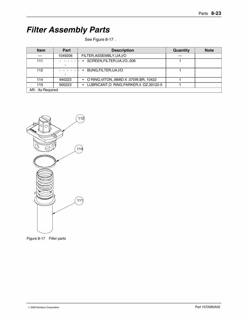
Parts 8‐23
Part 1072085A02� 2009 Nordson Corporation
Filter Assembly PartsSee Figure 8‐17 .
Item Part Description Quantity Note— 1049206 FILTER,ASSEMBLY,UA,I/O —
111 ‐ ‐ ‐ ‐ ‐ ‐‐
� SCREEN,FILTER,UA,I/O,.006 1
112 ‐ ‐ ‐ ‐ ‐ ‐‐
� BUNG,FILTER,UA,I/O 1
114 940223 � O RING,VITON,.989ID X .070W,BR, 10422 1115 900223 � LUBRICANT,O RING,PARKER,4 OZ,30122‐5 1
AR: As Required
114
111
112
Figure 8‐17 Filter parts

Parts8‐24
Part 1072085A02 � 2009 Nordson Corporation
Pump ShaftsThe pump shaft part number varies depending on the number of plates(slices) present on the applicator.
PartNumber� Number ofDispensing Modules
Lengthmm (in.)
1066275 2 106 (4.159)1066276 4 156 (6.127)1066277 6 206 (8.096)1066278 8 256 (10.064)1066279 10 306 (12.033)1066300 12 356 (14.001)1066301 14 406 (15.970)1066302 16 456 (17.938)1066303 18 506 (19.907)1066304 20 556 (21.875)1078575 22 606 (23.858)1078576 24 656 (25.827)

Parts 8‐25
Part 1072085A02� 2009 Nordson Corporation
Adhesive Diverter PlatesAdhesive diverter plates may be installed on a middle plate as needed toachieve a desired adhesive pattern. Each middle plate accommodates twodiverter plates.
NOTE: The arrows in the Flow column below indicate the direction(s) thatadhesive flow will be diverted as viewed from the back of (the side oppositethe modules) the applicator.
Part Number Designation No. Flow
1003273 ‐01
1009778 ‐02
1009779 ‐03
1034996‐04
1034998 ‐05
1023890 ‐06
1035001 ‐07
1035003 ‐08
1035005 ‐09
1035007 ‐10
1035009 ‐11

Parts8‐26
Part 1072085A02 � 2009 Nordson Corporation
Temperature SensorsAn applicator may have 100‐ohm platinum or 120‐ohm nickel temperaturesensors. Refer to the applicator‐specific reference drawings and/or toApplicator Configuration Code in Section 9, Technical Data, to determine theconfiguration of your applicator.
Fixed‐Depth SensorsSee Figure 8‐18 . Refer to Applicator Temperature Sensors in Section 2,Description, for an explanation of the function and location of the temperaturesensors on a slice applicator.
Item Part Description Quantity Note1 1064746 SENSOR, PT 100 OHM, 1 METER AR1 1079420 SENSOR, NI 120 OHM, 1 METER AR
AR: As Required
1
Figure 8‐18 Fixed‐depth sensor

Parts 8‐27
Part 1072085A02� 2009 Nordson Corporation
Immersion Sensors (Optional)See Figure 8‐19 . Refer to Applicator Temperature Sensors in Section 2,Description, for an explanation of the function and location of the temperaturesensors on a slice applicator.
Item Part Description Quantity Note1 1065911 ASSY,IMMERSION SENSOR, PT 100 OHM
(round)AR
1 1079440 SENSOR ASSY,IMMERSION,NI 120 OHM(round)
AR
2 1077200 ASSY,IMMERSION SENSOR,PT 100 OHM(square)
AR
2 1079442 SENSOR ASSY,IMMERSION,NI 120 OHM(square)
AR
AR: As Required
1
2
Figure 8‐19 Immersion sensors
Note: For wiring diagrams, refer to Section 9, Technical Data.

Parts8‐28
Part 1072085A02 � 2009 Nordson Corporation
Pressure TransducersSee Figure 8‐20 . Refer to Applicator Temperature Sensors in Section 2,Description, for an explanation of the function and location of the pressuretransducers on a slice applicator.
Item Part Description Quantity Note1 1090404 TRANSDUCER, MELT PRESSURE, 4-20mA AR1 1090405 TRANSDUCER, MELT PRESSURE, 0-10 VDC AR2 1090458 TRANSDUCER, ADHESIVE, MINI, CAN BUS,
100BAR�AR
AR: As Required
12
Figure 8‐20 Pressure transducers

Parts 8‐29
Part 1072085A02� 2009 Nordson Corporation
Air Input FittingsRefer to the applicator‐specific reference drawings and/or to ApplicatorConfiguration Code in Section 9, Technical Data, to determine theconfiguration of your applicator.
Module‐Actuating Air Input FittingsAll slice applicators require a module‐actuating air input to activate themodules. The following module‐actuating air input fittings are available.
Part Description Note466507 Fitting, air input, plug‐type, straight, G 1/4 thread, 10‐mm hose OD466506 Fitting, air input, plug‐type, 90‐degree, G 1/4 thread, 10‐mm hose OD
P/N 466506P/N 466507
Figure 8‐21 Module‐actuating air input fittings
Shared Process Air Input FittingsFor slice applicators that use shared process air, the following air inputfittings are available.
Part Description Note466509 Fitting, air input, plug‐type, straight, G 3/8 thread, 12‐mm hose OD466504 Fitting, air input, plug‐type, 90‐degree, G 3/8 thread, 12‐mm hose OD
P/N 466504P/N 466509
Figure 8‐22 Shared process air input fittings

Parts8‐30
Part 1072085A02 � 2009 Nordson Corporation
Hose Connector FittingsThis part of Section 8 provides a comprehensive list of available hoseconnector fittings.
Hose‐to‐Applicator Fitting Part NumbersSee Figure 8‐23 . The swivel fittings and the adapter shown in the next twotable can be connected to these fittings for more hose routing flexibility.
Hose Size Applicator BodyThread Size
Hose‐to‐Applicator Fitting
PartNumber�(Includes O‐Ring)
Description O‐RingPartNumber�
8 mm (5/16 in.),9/16in.x18 ��� threads,37� JIC, size 6
9/16 in. x 18 threads 972628 Straight fitting945032972647 45� swivel fitting
972646 90� swivel fitting13 mm (1/2 in.),3/4in.x16 ��� threads,37� JIC, size 8
9/16 in. x 18 threads 860587 Straight fitting945032134956 45� swivel fitting
134957 90� swivel fitting7/8 in. x 14 threads 972285 Straight fitting
941161972830 45� swivel fitting
16 mm (5/8 in.),11/16in.x12���threads, 37� JIC, size12
11/16 in. x 12 threads 972745 Straight fitting
940024972793 45� fitting972895 90� fitting
16 mm (5/8 in.),11/16�in.x12��threads, 37� JIC, size12
7/8 in. x 14 threads 972392 Straight fitting
941161816162 45� fitting972036 90� fitting
16 mm (5/8 in.),11/16in.x12���threads, 37� JIC, size12
9/16 in. x 18 threads 719024 Straight fitting
945032719047 45� fitting188825 90� fitting
1 2 3
Figure 8‐23 Typical hose‐to‐applicator fittings
1. Straight fitting 2. 45‐degree fitting 3. 90‐degree fitting
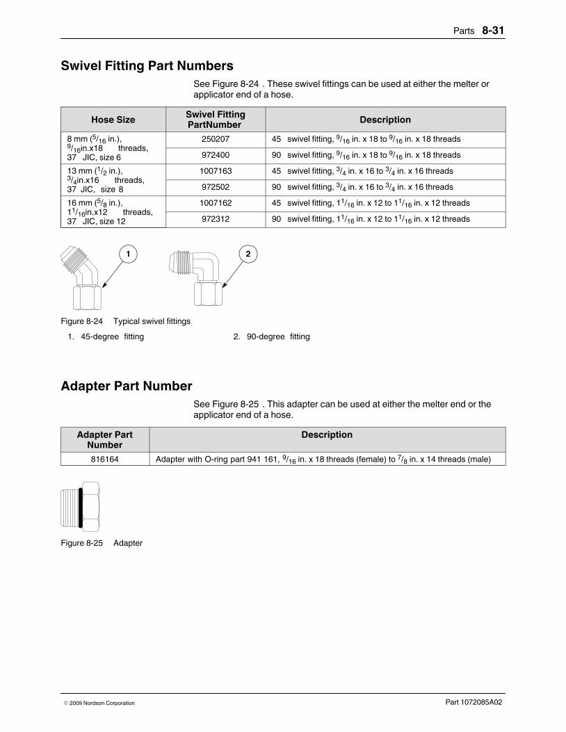
Parts 8‐31
Part 1072085A02� 2009 Nordson Corporation
Swivel Fitting Part NumbersSee Figure 8‐24 . These swivel fittings can be used at either the melter orapplicator end of a hose.
Hose Size Swivel FittingPartNumber� Description
8 mm (5/16 in.),9/16in.x18 ��� threads,37� JIC, size 6
250207 45� swivel fitting, 9/16 in. x 18 to 9/16 in. x 18 threads
972400 90� swivel fitting, 9/16 in. x 18 to 9/16 in. x 18 threads
13 mm (1/2 in.),3/4in.x16 ��� threads,37� JIC, �size 8
1007163 45� swivel fitting, 3/4 in. x 16 to 3/4 in. x 16 threads
972502 90� swivel fitting, 3/4 in. x 16 to 3/4 in. x 16 threads
16 mm (5/8 in.),11/16in.x12 ��� threads,37� JIC, size 12
1007162 45� swivel fitting, 11/16 in. x 12 to 11/16 in. x 12 threads
972312 90� swivel fitting, 11/16 in. x 12 to 11/16 in. x 12 threads
1 2
Figure 8‐24 Typical swivel fittings
1. 45‐degree fitting 2. 90‐degree fitting
Adapter Part NumberSee Figure 8‐25 . This adapter can be used at either the melter end or theapplicator end of a hose.
Adapter PartNumber
Description
816164 Adapter with O‐ring part 941 161, 9/16 in. x 18 threads (female) to 7/8 in. x 14 threads (male)
Figure 8‐25 Adapter

Parts8‐32
Part 1072085A02 � 2009 Nordson Corporation
Junction Boxes and Connecting CablesJunction boxes and connecting cables are required to make electricalconnections between the applicator and the control system(s).
Cordset Junction BoxesSee Figure 8‐26 .
Item Part Description Quantity Note1 1077353 JUNCTION BOX, CENTER HEAT ZONE, G3 AR2 1077354 JUNCTION BOX, END HEAT ZONES, G3 AR
AR: As Required
1 2
Figure 8‐26 Cordset junction boxes
Note: For wiring diagrams, refer to Section 9, Technical Data.
Cordset Junction Box Splitter CableSee Figure 8‐27 .
Part Description Note1077355 CABLE, TWO ZONE JUNCTION, G3
Figure 8‐27 Cordset junction box splitter cable
Note: For wiring diagrams, refer to Section 9, Technical Data.

Parts 8‐33
Part 1072085A02� 2009 Nordson Corporation
Lenze Motor CablesSee Figure 8‐28 .
Power CablesPart Length Description
730831 5 m (16.4 ft) Connection cable, motor, Lenze, 5 m/1.5 mm2
201483 10 m (32.8 ft) Connection cable, motor, Lenze,10 m/1.5 mm2
730846 12 m (39.4 ft) Connection cable, motor, Lenze,12 m/1.5 mm2
446745 15 m (49.2 ft) Connection cable, motor, Lenze,15 m/2.5 mm2
402639 20 m (65.6 ft) Connection cable, motor, Lenze, 20 m/1.5 mm2
785337 25 m (82.0 ft) Connection cable, motor, Lenze, 2 5m/1.5 mm2
466384 30 m (98.4 ft) Connection cable, motor, Lenze, 3 0m/1.5 mm2
466386 35 m (114.9 ft) Connection cable, motor, Lenze, 3 5m/1.5 mm2
7102355 40 m (131.2 ft) Connection cable, motor, Lenze, 4 0m/1.5 mm2
Encoder Cables 730832 5 m (16.4 ft) Connection cable, resolver, Lenze motor, 5 m418858 10 m (32.8 ft) Connection cable, resolver, Lenze motor, 10 m730847 12 m (39.4 ft) Connection cable, resolver, Lenze motor, 12 m446746 15 m (49.2 ft) Connection cable, resolver, Lenze motor, 15 m402640 20 m (65.6 ft) Connection cable, resolver, Lenze motor, 20 m785335 25 m (82.0 ft) Connection cable, resolver, Lenze motor, 25 m466385 30 m (98.4 ft) Connection cable, resolver, Lenze motor, 30 m466387 35 m (114.9 ft) Connection cable, resolver, Lenze motor, 35 m
7102358 40 m (131.2 ft) Connection cable, resolver, Lenze motor, 40 m
Figure 8‐28 Lenze motor cable (encoder cable not shown)
Note: For wiring diagrams, refer to Section 9, Technical Data.
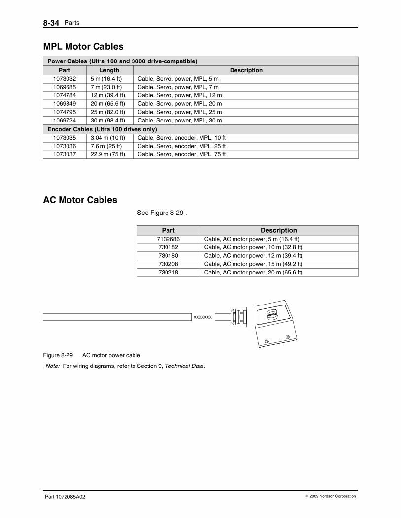
Parts8‐34
Part 1072085A02 � 2009 Nordson Corporation
MPL Motor CablesPower Cables (Ultra 100 and 3000 drive‐compatible)
Part Length Description1073032 5 m (16.4 ft) Cable, Servo, power, MPL, 5 m1069685 7 m (23.0 ft) Cable, Servo, power, MPL, 7 m1074784 12 m (39.4 ft) Cable, Servo, power, MPL, 12 m1069849 20 m (65.6 ft) Cable, Servo, power, MPL, 20 m1074795 25 m (82.0 ft) Cable, Servo, power, MPL, 25 m1069724 30 m (98.4 ft) Cable, Servo, power, MPL, 30 m
Encoder Cables (Ultra 100 drives only)1073035 3.04 m (10 ft) Cable, Servo, encoder, MPL, 10 ft1073036 7.6 m (25 ft) Cable, Servo, encoder, MPL, 25 ft1073037 22.9 m (75 ft) Cable, Servo, encoder, MPL, 75 ft
AC Motor CablesSee Figure 8‐29 .
Part Description7132686 Cable, AC motor power, 5 m (16.4 ft)730182 Cable, AC motor power, 10 m (32.8 ft)730180 Cable, AC motor power, 12 m (39.4 ft)730208 Cable, AC motor power, 15 m (49.2 ft)730218 Cable, AC motor power, 20 m (65.6 ft)
XXXXXXX
Figure 8‐29 AC motor power cable
Note: For wiring diagrams, refer to Section 9, Technical Data.

Parts 8‐35
Part 1072085A02� 2009 Nordson Corporation
Pressure Transducer CablesSee Figure 8‐30 .
Part Description Note1090805 CABLE, SLICE, TRANSDUCER, 2M, QUICK CONNECT, TR AR1090806 CABLE, SLICE, TRANSDUCER, 10M, QUICK CONNECT, TR AR1090807 CABLE, SLICE, TRANSDUCER, 15M, QUICK CONNECT, TR AR1090808 CABLE, SLICE, TRANSDUCER, 20M, QUICK CONNECT, TR AR1090809 CABLE, SLICE, TRANSDUCER, 25M, QUICK CONNECT, TR AR1090810 CABLE, SLICE, TRANSDUCER, 30M, QUICK CONNECT, TR AR1090811 CABLE, SLICE, TRANSDUCER, 40M, QUICK CONNECT, TR AR1090812 CABLE, SLICE, TRANSDUCER, 50M, QUICK CONNECT, TR AR
AR: As Required
Figure 8‐30 Pressure transducer cable
Note: For wiring diagrams, refer to Section 9, Technical Data.

Parts8‐36
Part 1072085A02 � 2009 Nordson Corporation
M‐Style Hose Extension CablesSee Figure 8‐31 .
Part Description Note1070747 Cable, extension, M‐style, hose, 1 m1070748 Cable, extension, M‐style, hose, 2 m1070749 Cable, extension, M‐style, hose, 4 m1070750 Cable, extension, M‐style, hose, 6 m1070751 Cable, extension, M‐style, hose, 8 m1070752 Cable, extension, M‐style, hose, 10 m1070753 Cable, extension, M‐style, hose, 12 m1070754 Cable, extension, M‐style, hose, 15 m1070755 Cable, extension, M‐style, hose, 20 m1070756 Cable, extension, M‐style, hose, 25 m1074883 Cable, extension, M‐style, hose, 40 m1074661 Cable, extension, M‐style, hose, 50 m
'L'
Figure 8‐31 M‐style hose extension cable
Note: For wiring diagrams, refer to Section 9, Technical Data.

Parts 8‐37
Part 1072085A02� 2009 Nordson Corporation
T‐Style Extension CablesSee Figure 8‐32 .
Part Description115767 Cable, T‐style, extension, 0.6 m (2 ft)115577 Cable, T‐style, extension, 1.8 m (6 ft)115578 Cable, T‐style, extension, 3.5 m (12 ft)115579 Cable, T‐style, extension, 5.5 m (18 ft)115580 Cable, T‐style, extension, 7.3 m (24 ft)115581 Cable, T‐style, extension, 9.1 m (30 ft)152812 Cable, T‐style, extension, 12.2 m (40 ft)149958 Cable, T‐style, extension, 15.2 m (50 ft)
Figure 8‐32 T‐style extension cable
Note: For wiring diagrams, refer to Section 9, Technical Data.
T‐Style Splitter CableSee Figure 8‐33 . This cable is required when connecting the slice applicatorto a VersaBlue melter. A maximum of 1800 W may be connected to aVersaBlue melter hose/gun connector. A slice applicator heated zone can goup to 1500 W.
Part Description310893 Cable, splitter, T‐style
Figure 8‐33 T‐style splitter cable
Note: For wiring diagrams, refer to Section 9, Technical Data.

Parts8‐38
Part 1072085A02 � 2009 Nordson Corporation
M‐Style to T‐Style Adapter CableSee Figure 8‐34 .
Part Description1080325 Cable, adapter, M to T‐style, 0.3 m
Figure 8‐34 M‐style to T‐style adapter cable
Note: For wiring diagrams, refer to Section 9, Technical Data.

Parts 8‐39
Part 1072085A02� 2009 Nordson Corporation
Recommended Spare Parts and Supplies
Table 8‐3 Recommended Spare PartsAssembly Part Description
End plates 1049206 FILTER,ASSEMBLY,UA,I/O1095522 KIT, REBUILD, SLICE, O‐RING, END PLATES, G31095523 KIT, REBUILD, SLICE, O‐RING, PER SLICE, G3466507 Fitting, air input, plug‐type, straight, G 1/4 thread, 10‐mm hose OD
(module‐actuating air input fitting)466506 Fitting, air input, plug‐type, 90‐degree, G 1/4 thread, 10‐mm hose
OD (module‐actuating air input fitting)466509 Fitting, air input, plug‐type, straight, G 3/8 thread, 12‐mm hose OD
(shared process air input fitting)466504 Fitting, air input, plug‐type, 90‐degree, G 3/8 thread, 12‐mm hose
OD (shared process air input fitting)Air manifold 1064759 GASKET, HAM SEAL
1064761 SEAL, HAM SIDE, SHARED AIR PORT1065965 SEAL, HAM MOUNTING, SCREW466561 PLUG‐TYPE THREAD‐IN FTG. ‐D08‐G1/8‐0000 (8 mm) (present
only on independent control air manifolds)Drive assembly 1064958 MOTOR,SERVO, MPL,0.73 KW (1.0HP)
1064737 REDUCER, SERVO, GEAR, 10:1, INLINE1070568 REDUCER, SERVO, GEAR, 10:1, 90 DEGREE1055615 MOTOR,SERVO, MPL,0.73 KW (1.0HP)1079170 REDUCER,SERVO,GEAR,10:1,IN‐LINE, LENZE1079156 REDUCER,SERVO,GEAR,10:1,90 DEG, LENZE1081978 MOTOR,BS03‐34V/D06LA4‐TOF‐ST/UL‐SP,.25KW (AC motor)
Pump ‐ ‐ ‐ ‐ ‐ ‐ Pump, gear (refer to Tables 8‐1 and 8‐2 for part numbers)1003271 NDV A14328,SEAL MODULAR PUMP‐DFMU
940081 O RING,VITON, .188X.313X.063, 104081031500 SEAL,CRUSH,RUPTURE DISK,SLICE
Pressure transducers 1090404 TRANSDUCER, MELT PRESSURE, 4-20mA1090405 TRANSDUCER, MELT PRESSURE, 0-10 VDC1090458 TRANSDUCER, ADHESIVE, MINI, CAN BUS, 100 BAR
Electrical 1064747 CARTRIDGE, HEATER, 3/8 DIA, 500 WATT1064746 SENSOR, PT 100 OHM, 1 METER1079420 SENSOR, NI 120 OHM, 1 METER1065911 ASSY,IMMERSION SENSOR, PT 100 OHM (round)1079440 SENSOR ASSY,IMMERSION,NI 120 OHM (round)1077200 ASSY,IMMERSION SENSOR,PT 100 OHM (square)1079442 SENSOR ASSY,IMMERSION,NI 120 OHM (square)1077355 CABLE, TWO ZONE JUNCTION, G3

Parts8‐40
Part 1072085A02 � 2009 Nordson Corporation

Technical Data 9‐1
Part 1072085A02� 2009 Nordson Corporation
Section 9Technical Data
Applicator SpecificationsApplicator System Item Specification
Hydraulic system Minimum operating temperature (ambient) 25 � C (77 � F)Maximum operating temperature 204 � C (400 � F)Adhesive viscosity 2,000-15,000 cpsMinimum adhesive input pressure 5.5 bar (80 psi)Maximum adhesive input pressure 103.4 bar (1,500 psi)Nominal operating adhesive input pressure 10.3-20.7 bar (150-300psi)�Rupture disk burst pressure (maximumadhesive output pressure)
114 bar (1,650 psi) at 163�� C(325� � F), 3%tolerance�
Pneumatic system Minimum module‐actuating air pressure 5.2 bar (75 psi)Maximum module‐actuating air pressure 6.2 bar (90 psi)Nominal module‐actuating air pressure 5.5 bar (80 psi)Maximum module process air flow (permodule)
0.057 m3/min (2 scfm)
Minimum process air pressure 0.1 bar (1 psi)Maximum process air pressure 6.9 bar (100 psi)Nominal process air pressure 0.7–4.1 bar (10-60 psi)Maximum differential pressure 5.2 bar (75 psi)
Electrical system Supply voltage 240 VACHeated zones One adhesive; one pattern airTemperature sensors 100‐ohm platinum RTD or
120‐ohm nickel RTDSolenoid valve input voltage 24 VDC or 110 VAC
Continued...

Technical Data9‐2
Part 1072085A02 � 2009 Nordson Corporation
Applicator Specifications (contd.)
Applicator System Item SpecificationMotor Motor type MPL, Lenze, or AC; inline or
right‐angle
Gear reducer type Single reduction planetary gearGear reducer ratio MPL or Lenze: 10:1
AC: 7.01:1PumpsNOTE: When orderinga pump, choose a pumpsize that will allow youto achieve the desiredflow rate at a pumpspeed as close to 60rpm as possible.Sixtyrpm �is the speedat which the greatestpump efficiency isobtained.
Minimum pump speed 10 rpm
Maximum pump speed 150 rpm
Recommended pump speed 60 rpm
Maximum output torque 34.6 N�m (300 in.‐lb)
Pattern control Minimum pattern width per module 0.3175 cm (0.125 in.)Maximum pattern width per module 25 mm (0.98 in.)
Fluid Compatibility:Rated for use with all commercially available, pressure sensitive, hot meltadhesives, with the exception of any compounds that contain polyamides.
Disclaimer:The equipment specifications above will be under warranty according toNordson standard agreements. Nordson will cover the cost of repair and orreplacement of the equipment due to failure. However, due to situationsbeyond our control, such as misuse, equipment modification, unreasonableuse, neglect, and lack of maintenance, Nordson will not be liable for personalinjuries and associated cost thereof due to equipment failure under suchconditions.
Nomenclature:Cv‐pneumatic conductance is reported as a number expressing the ability ofa fluid to flow under a p (pressure drop) and is often referred to as flowcapability, or more commonly known as flow coefficient.

Technical Data 9‐3
Part 1072085A02� 2009 Nordson Corporation
Applicator DimensionsRefer to the applicator‐specific drawing for the dimensions of yourapplicator.
Torque SpecificationsThese torque specifications are also stated within the appropriate repairprocedures.
Fastener Torque SpecificationAir manifold screws 2.3 N�m (20 in.‐lb)
Immersion sensor fitting 2.8 N�m (25 in.‐lb)
Heater screws 2.3 N�m (20 in.‐lb)
Pump clamp screws 2.8-3.4 N�m (25-30 in.‐lb)
Pressure transducer mounting screws 1.7 N�m (15 in.‐lb)
Recirculation plate assembly screws 12.4 N�m (110�in.‐lb)
Rupture disk 5.6 N�m (50 in.‐lb)

Technical Data9‐4
Part 1072085A02 � 2009 Nordson Corporation
Wiring Diagrams
Electrical SchematicRefer to the reference drawings provided with the applicator.
Applicator Cordset Pin Positions
RED (+)
RED / WHITE (-)
GREEN(GROUND)
2
3
1
Figure 9‐1 Heater cordset pins
PIN OUTS:
SENSOR - (BLACK)1.SENSOR + (WHITE)2.SHIELD3.SENSOR - (RED)4.
3
1
2
4
Figure 9‐2 Sensor cordset pins

Technical Data 9‐5
Part 1072085A02� 2009 Nordson Corporation
PIN OUTS:
SENSOR +1.SENSOR -2.SHIELD3.SPARE4.
3
24
1
Figure 9‐3 Round connector immersion sensor cordset pins
PIN #1 (NONE)
(BOTH RED WIRES COMBINED)
PIN #5 (NONE)
PIN #2 (NONE)
PE (GROUND)
PIN #3 RTD-RED (2X)
PIN #4 RTD-WHITE
Figure 9‐4 Square connector immersion sensor cordset pins

Technical Data9‐6
Part 1072085A02 � 2009 Nordson Corporation
Cordset Junction Boxes
25.401.00
70.362.7786.40
3.40
36.601.44 .281[7.14] THRU2X
1.3634.50
D
E
A
B
C
DETAIL DSCALE 1 : 1 DETAIL E
SCALE 1 : 1
DETAIL ASCALE 1 : 1
DETAIL BSCALE 1 : 1
DETAIL CSCALE 1 : 1
1
2
1
23
1
23
41
6
54
3
2
1
2
3 3
45 45
45 45
HTR 1 HTR 2
HTR 3RTD 2
P1
3
3
3
1�
WIRING DIAGRAM
HEATER L1
HEATER L2
GN
DRTD
+RTD
-RTD
-/SHIELD
2 3 4 5 6
12
12
3
12
4
12
983.86
642.52
Figure 9‐5 Center zone cordset junction box pin positions

Technical Data 9‐7
Part 1072085A02� 2009 Nordson Corporation
WIRING DIAGRAM
25.401.00
70.362.7786.40
3.40
36.601.44 .281[7.14] THRU2X
1.3634.50
D
E
A
B
F
C
DETAIL BSCALE 1 : 1
DETAIL ASCALE 1 : 1
DETAIL CSCALE 1 : 1
DETAIL DSCALE 1 : 1
DETAIL ESCALE 1 : 1
DETAIL FSCALE 1 : 1
5 4
1
23
1
23
41
6
54
3
2
12
3
1
2
1 2
36
45 45
45 45
RTD
2 S
HIE
LD
RTD 2-
RTD G
ND
RTD 2 -
RTD 2 +
HEA
TER
2 L
1
RTD SH
IELD
RTD 1+
HEATER 1 G
RDH
EATER 1 L2H
EATER 1 L1
P2
P1
4321
321
RTD 2
HTR 2
4321
321
RTD 1
HTR 1
54321
54321 6
6
HEA
TER
2 L
2H
EATE
R 2
GRD
RTD
2+
RTD
2-
CAS
E G
ROUN
D
983.86
642.52
Figure 9‐6 End zone cordset junction box pin positions

Technical Data9‐8
Part 1072085A02 � 2009 Nordson Corporation
Cordset Junction Box Splitter Cable
PLUG #1
A1HTR
A2HTR
A3HTR
A4HTR
B1RTD
B2RTD
B3RTD
B4RTD
PLUG #2
D D
3-GRDB2
6-RTD
A11-HTR
B25-RTD
B14-RTD
PE1
2-HTRA2
3-GRDPE2
A31 -HTR
B45-RTD
B46-RTD
A42-HTR
4-RTDB3
A
B
C
Figure 9‐7 Cordset junction box splitter cable pin positions

Technical Data 9‐9
Part 1072085A02� 2009 Nordson Corporation
Motor Cables
Figure 9‐8 MPL motor power and encoder cable wiring diagrams

Technical Data9‐10
Part 1072085A02 � 2009 Nordson Corporation
Motor Cables (contd.)
Figure 9‐9 Lenze motor power cable wiring diagram
Figure 9‐10 Lenze motor encoder cable wiring diagram

Technical Data 9‐11
Part 1072085A02� 2009 Nordson Corporation
XXXXXXX
6
BLK 1GRN/YEL
END WIRINGCONNECTOR
12345
BLK 7 7
10
BLK 6
BLK 2BLK 3BLK 4BLK 5
BLK 8BLK 9BLK 10
89
PIN FUNCTION123
910
PE
L1L2L3
GNDTSTATTSTAT
Figure 9‐11 AC motor power cable wiring diagram
Pressure Transducer Cable
CONN ”A”WIRING DIAGRAM
XXXXXXXXXXXXXX
FUNCTION COLOR CONN”A” CONN”B” SIG+ RED C 2 SIG- BLK D 4 EXC+ BRN A 1 EXC- ORG B 3
CONN ”B”
Figure 9‐12 Pressure transducer cable wiring diagram

Technical Data9‐12
Part 1072085A02 � 2009 Nordson Corporation
Extension, Splitter, and Adapter Cables
BLK 1
GRN/YEL
A1
CONNECTOR END WIRING
A1
A2 A2
A3 A3
A4 A4
B1 B1
B2 B2
B3 B3
B4 B4
C2 C2
C3 C3
CONN ”A” CONN ”B”
BLK 2
BLK 3
BLK 4
BLK 5
BLK 6
BLK 7
BLK 8
BLK 9
BLK 10
Figure 9‐13 M‐style extension cable wiring diagram
1
5 63 4
8
1
2
3
4
5
6
8
10
11
APPLICATOR HEATER
APPLICATOR RTD
HOSE/APPLICATOR RTD
GROUND
HOSE RTD
HOSE HEATER
HOSE HEATER
9
12
APPLICATOR HEATER
2
9 10 11 12
4
8 6
2 1
5
3
12 11 10 9
HIGH POWER APPLICATOR HEATER
Figure 9‐14 T‐style extension cable wiring diagram

Technical Data 9‐13
Part 1072085A02� 2009 Nordson Corporation
18 GABLUE/WHT
GRN/YEL
GRN/YELGRAY
BROWN
18 GA22 GA
18 GA22 GA
22 GA18 GA
TAN
18 GA22 GA
18 GA
2
WIRING DIAGRAM
83
6
11
1048
125
910
75
3
1
CONNECTOR #1 (PINS)
(SOCKETS)
(SOCKETS)CONNECTOR #3
CONNECTOR #2
GUN END
UNIT END
910111264
7
84
561
23
1112
REDORANGE
BLUEBROWN
97
12
8
Figure 9‐15 T‐style splitter cable wiring diagram
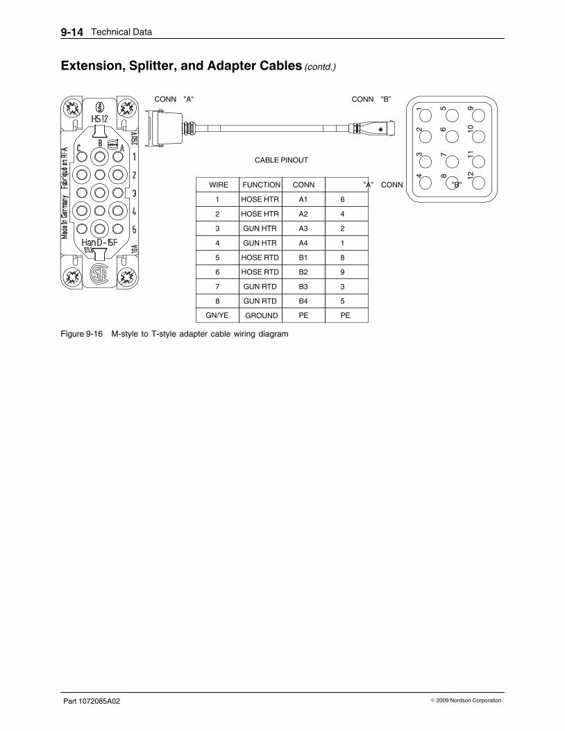
Technical Data9‐14
Part 1072085A02 � 2009 Nordson Corporation
Extension, Splitter, and Adapter Cables (contd.)
CONN ”A” CONN ”B”
CABLE PINOUT
WIRE�������� ��CONN ”A” ��CONN ”B”
HOSE HTR1
HOSE HTR2
GUN HTR3
GUN HTR4
HOSE RTD5
HOSE RTD6
GUN RTD7
GUN RTD8
GROUND
FUNCTION
A1
A2
A3
A4
B1
B2
B3
B4
6
4
2
1
8
9
3
5
GN/YE PE PE
Figure 9‐16 M‐style to T‐style adapter cable wiring diagram

Technical Data 9‐15
Part 1072085A02� 2009 Nordson Corporation
Applicator Configuration CodeUniversal slice applicators are configurable, which means that eachapplicator is constructed according to specific choices made when theapplicator was ordered. A configuration code that represents theconfiguration of the applicator is stamped in the “Model” portion of theinformation plate, which is typically located on drive side end plate, as shownin Figure 9‐17 . To determine the configuration of your applicator, obtain itsconfiguration code and refer to Figure�9‐18 and Table 9‐1 .
Figure 9‐17 Typical location of the information plate on an applicator
Cod
e Po
sitio
ns 1
-7
Cod
e Po
sitio
n 11
Cod
e Po
sitio
n 12
Cod
e Po
sitio
n 13
Cod
e Po
sitio
n 14
Cod
e Po
sitio
n 15
Cod
e Po
sitio
n 17
Cod
e Po
sitio
ns 8
-9
Cod
e Po
sitio
n 16
Cod
e Po
sitio
n 10
Cod
e Po
sitio
n 18
Cod
e Po
sitio
n 19
Cod
e Po
sitio
n 20
Cod
e Po
sitio
n 21
Cod
e Po
sitio
n 22
Cod
e Po
sitio
n 25
Cod
e Po
sitio
n 24
G3-150-06-LLPXXFXAXXXXX/X
Figure 9‐18 Configuration code positions
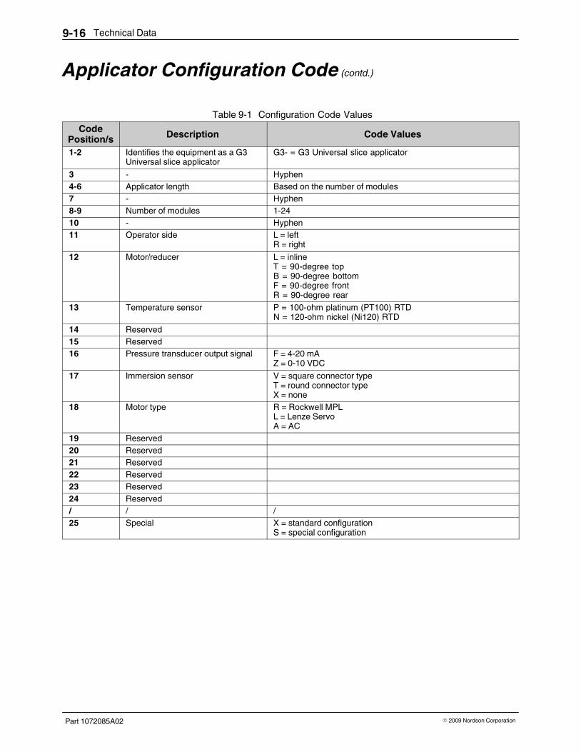
Technical Data9‐16
Part 1072085A02 � 2009 Nordson Corporation
Applicator Configuration Code (contd.)
Table 9‐1 Configuration Code ValuesCode
Position/s Description Code Values
1-2 Identifies the equipment as a G3Universal slice applicator
G3‐ = G3 Universal slice applicator
3 ‐ Hyphen4-6 Applicator length Based on the number of modules7 ‐ Hyphen8-9 Number of modules 1-2410 ‐ Hyphen11 Operator side L = left
R = right12 Motor/reducer L = inline
T = 90‐degree topB = 90‐degree bottomF = 90‐degree frontR = 90‐degree rear
13 Temperature sensor P = 100‐ohm platinum (PT100) RTDN = 120‐ohm nickel (Ni120) RTD
14 Reserved15 Reserved16 Pressure transducer output signal F = 4-20 mA
Z = 0-10 VDC17 Immersion sensor V = square connector type
T = round connector typeX = none
18 Motor type R = Rockwell MPLL = Lenze ServoA = AC
19 Reserved20 Reserved21 Reserved22 Reserved23 Reserved24 Reserved/ / /25 Special X = standard configuration
S = special configuration

EC Declaration of Conformityfor Adhesive and Sealant Application Equipment
conforming to European Council Directives
PRODUCT:
Universal� Slice Applicator
APPLICABLE DIRECTIVES:
Machinery Directive: 2006/42/ECLow Voltage Directive: 2006/95/EC
STANDARDS USED TO VERIFY COMPLIANCE:
EN ISO 12100 EN 60204-1EN ISO 13732-1
PRINCIPLES:
This product has been manufactured according to good engineering practice.
The product specified conforms to the directives and standards described above.
Technical File Contact:
Dieter Ziesmer
Nordson Engineering GmbH
Lilienthalstrasse 6
21337 Lueneburg
GERMANY
Date: 12/August/2010
Peter Lambert, Vice PresidentAdhesives Dispensing Systems
DOC064R3
Nordson Corporation � 28601 Clemens Road � Westlake, Ohio
