series h-100 guns - nordsonemanuals.nordson.com/adhesives/english_manuals/237558.pdf · preparing...
TRANSCRIPT

Series H-100 Guns
Customer Product ManualPart 237 558D
NORDSON CORPORATION � Duluth, Georgiawww.nordson.com

� 2002 Nordson CorporationAll rights reserved
237558DIssued 6/02
42-H100-MA-01
For CE Declaration, refer to melter manual.
Nordson Corporation welcomes requests for information, comments and inquiries about its products. Generalinformation about Nordson can be found on the Internet using the following address: http://www.nordson.com.
Address all correspondence to:
Nordson CorporationAttn: Customer Service11475 Lakefield Drive
Duluth, GA 30097
Notice
This is a Nordson Corporation publication which is protected by copyright. Original copyright date 1998. No part ofthis document may be photocopied, reproduced, or translated to another language without the prior written consent
of Nordson Corporation. The information contained in this publication is subject to change without notice.
Trademarks
AquaGuard, Blue Box, Control Coat, Equi=Bead, FoamMelt, FoamMix, Helix, Hot Shot, Hot Stitch, Meltex,MicroSet, MultiScan, Nordson, the Nordson logo, OmniScan, Package of Values, Porous Coat, Posi-Stop, ProLink,
PRX, RBX, Shur-Lock, UniScan, UpTime, and Versa-Spray are registered trademarks of Nordson Corporation.
BetterBook, CF, Controlled Fiberization, Eclipse, Saturn, Seal Sentry, Swirl Coat, and Vista are trademarks of Nordson Corporation.
Viton is a registered trademark of E.I. DuPont de Nemours & Co.

Table of Contents i
� 2002 Nordson CorporationAll rights reserved
237558DIssued 6/02
42-H100-MA-01
Table of Contents
1. Safety 1. . . . . . . . . . . . . . . . . . . . . . . . . . . . . . . . . . . . . . . . . . . . . . . . . . . . .
Safety Symbols 2. . . . . . . . . . . . . . . . . . . . . . . . . . . . . . . . . . . . . . . . . . .
Qualified Personnel 3. . . . . . . . . . . . . . . . . . . . . . . . . . . . . . . . . . . . . . .
Intended Use 3. . . . . . . . . . . . . . . . . . . . . . . . . . . . . . . . . . . . . . . . . . . . .
Installation and Electrical Connections 4. . . . . . . . . . . . . . . . . . . . . . .
Operation 4. . . . . . . . . . . . . . . . . . . . . . . . . . . . . . . . . . . . . . . . . . . . . . . .
Less-Obvious Dangers 5. . . . . . . . . . . . . . . . . . . . . . . . . . . . . . . . . .
Action in the Event of Unit Malfunction 5. . . . . . . . . . . . . . . . . . . .
Danger of Burns 6. . . . . . . . . . . . . . . . . . . . . . . . . . . . . . . . . . . . . . . .
Maintenance/Repair 6. . . . . . . . . . . . . . . . . . . . . . . . . . . . . . . . . . . . . . .
Cleaning 7. . . . . . . . . . . . . . . . . . . . . . . . . . . . . . . . . . . . . . . . . . . . . . . . .
Thermoplastic Hot Melt Material 8. . . . . . . . . . . . . . . . . . . . . . . . . . . .
Equipment and Material Disposal 8. . . . . . . . . . . . . . . . . . . . . . . . . . .
Polyurethane Reactive (PUR) Hot Melt Material 8. . . . . . . . . . . . . . .
2. Description 10. . . . . . . . . . . . . . . . . . . . . . . . . . . . . . . . . . . . . . . . . . . . . . . .
Specifications 11. . . . . . . . . . . . . . . . . . . . . . . . . . . . . . . . . . . . . . . . . . .
Dimensions 12. . . . . . . . . . . . . . . . . . . . . . . . . . . . . . . . . . . . . . . . . . . . .
3. Installation 12. . . . . . . . . . . . . . . . . . . . . . . . . . . . . . . . . . . . . . . . . . . . . . . .
Inspecting the Gun 12. . . . . . . . . . . . . . . . . . . . . . . . . . . . . . . . . . . . . . .
Items Needed 13. . . . . . . . . . . . . . . . . . . . . . . . . . . . . . . . . . . . . . . . . . .
Installing the Gun 13. . . . . . . . . . . . . . . . . . . . . . . . . . . . . . . . . . . . . . . .
Connecting the Air Supply 14. . . . . . . . . . . . . . . . . . . . . . . . . . . . . . . .
Solenoid Valve Power Supply Connection 14. . . . . . . . . . . . . . . .
Air Supply Connection 16. . . . . . . . . . . . . . . . . . . . . . . . . . . . . . . . .
Connecting the Hose 17. . . . . . . . . . . . . . . . . . . . . . . . . . . . . . . . . . . . .
Preparing the Gun for Operation 17. . . . . . . . . . . . . . . . . . . . . . . . . . .

Table of Contentsii
� 2002 Nordson CorporationAll rights reserved
237558DIssued 6/02
42-H100-MA-01
4. Operation 18. . . . . . . . . . . . . . . . . . . . . . . . . . . . . . . . . . . . . . . . . . . . . . . . .
Starting the System 18. . . . . . . . . . . . . . . . . . . . . . . . . . . . . . . . . . . . . .
Adjusting Adhesive Application 19. . . . . . . . . . . . . . . . . . . . . . . . . . . .
Shutting Down the System 19. . . . . . . . . . . . . . . . . . . . . . . . . . . . . . . .
5. Troubleshooting 20. . . . . . . . . . . . . . . . . . . . . . . . . . . . . . . . . . . . . . . . . . . .
Troubleshooting Table 20. . . . . . . . . . . . . . . . . . . . . . . . . . . . . . . . . . . .
Checking the Air Pressure Regulator 21. . . . . . . . . . . . . . . . . . . . . . .
Checking the Solenoid Valve 21. . . . . . . . . . . . . . . . . . . . . . . . . . . . . .
Checking for a Clogged Gun Nozzle, Module, or Manifold 22. . . . .
Checking a Heater 24. . . . . . . . . . . . . . . . . . . . . . . . . . . . . . . . . . . . . . .
Checking the RTD 25. . . . . . . . . . . . . . . . . . . . . . . . . . . . . . . . . . . . . . .
6. Repair 28. . . . . . . . . . . . . . . . . . . . . . . . . . . . . . . . . . . . . . . . . . . . . . . . . . . .
Cleaning Nozzles 28. . . . . . . . . . . . . . . . . . . . . . . . . . . . . . . . . . . . . . . .
Replacing the Filter 31. . . . . . . . . . . . . . . . . . . . . . . . . . . . . . . . . . . . . .
Replacing a Gun Module 33. . . . . . . . . . . . . . . . . . . . . . . . . . . . . . . . . .
Replacing a Heater 34. . . . . . . . . . . . . . . . . . . . . . . . . . . . . . . . . . . . . . .
Replacing the RTD 37. . . . . . . . . . . . . . . . . . . . . . . . . . . . . . . . . . . . . . .
7. Parts 39. . . . . . . . . . . . . . . . . . . . . . . . . . . . . . . . . . . . . . . . . . . . . . . . . . . . .
Using the Illustrated Parts List 39. . . . . . . . . . . . . . . . . . . . . . . . . . . . .
H-100 Gun Parts 40. . . . . . . . . . . . . . . . . . . . . . . . . . . . . . . . . . . . . . . . .

Series H-100 Guns 1
� 2002 Nordson CorporationAll rights reserved
237558DIssued 6/02
42-H100-MA-01
Series H-100 Guns
WARNING: Allow only qualified personnel to perform thefollowing tasks. Follow the safety instructions in this documentand all other related documentation.
WARNING: Risk of personal injury. If you remove thepreinstalled solenoid valve, correct reinstallation is required toprevent normally open gun operation. A normally open gun willdispense adhesive uncontrollably until the primary air supply isinterrupted.
CAUTION: Risk of equipment damage. H-100 gun modulesoperate as air-open, air-close valves. The loss or elimination ofair pressure to the gun solenoid valve without a correspondingreduction in system hydraulic pressure may cause the gunmodules to remain open.
Safety instructions contained in this section and throughout thisdocument apply to tasks that may be performed with or on the unit.Warnings related to specific safety concerns are included within the textas appropriate. It is very important that these safety instructions arealways followed. Failure to do so could result in personal injury and/ordamage to the unit or other equipment.
With this in mind, here are some basic safety recommendations:
� Read and become familiar with this Safety section prior to installing,operating, maintaining, or repairing the unit.
� Read and follow the warnings which appear within the text and arerelated to specific tasks.
� Store this document within easy reach of personnel operating ormaintaining the unit.
� Wear personal protective equipment and clothing such as safetygoggles and gloves.
� Become familiar with and follow all safety instructions prescribed bythe company, general accident-prevention regulations, andgovernment safety regulations.
1. Safety

Series H-100 Guns2
� 2002 Nordson CorporationAll rights reserved
237558DIssued 6/02
42-H100-MA-01
The following symbols are used to warn against dangers or possiblesources of danger. Become familiar with them! Failure to heed awarning could lead to personal injury and/or damage to the unit or otherequipment.
WARNING: Failure to observe may result in personal injury,death, or equipment damage.
WARNING: Risk of electrical shock. Failure to observe mayresult in personal injury, death, or equipment damage.
WARNING: Disconnect equipment from the line voltage.
WARNING: Hot! Risk of burns. Wear heat-protective clothing,safety goggles, and/or heat-protective gloves depending on thesymbols shown.
WARNING: Risk of explosion or fire. Fire, open flames, andsmoking prohibited.
WARNING: System or material pressurized. Relieve pressure.Failure to observe may result in serious burns.
CAUTION: Failure to observe may result in equipmentdamage.
CAUTION: Hot surface. Failure to observe may result inburns.
Safety Symbols

Series H-100 Guns 3
� 2002 Nordson CorporationAll rights reserved
237558DIssued 6/02
42-H100-MA-01
“Qualified personnel” is defined here as individuals who thoroughlyunderstand the equipment and its safe operation, maintenance, andrepair. Qualified personnel are physically capable of performing therequired tasks, familiar with all relevant safety rules and regulations, andhave been trained to safely install, operate, maintain, and/or repair theequipment. It is the responsibility of the company operating theequipment to see that its personnel meet these requirements.
The unit is designed and intended to be used only for the purposedescribed in the Description section. Uses not in accordance with thatsection or as described in this document are considered unintended usesand not in accordance with governing regulations.
WARNING: Use of this equipment in ways other thandescribed in this document may result in personal injury, death,or equipment damage.
The following actions of the owner or operator of the unit are some, butnot all, examples of unintended use which would permit Nordson to claimit is not responsible for personal injury or property damage arising fromsuch unintended use:
� Unapproved modifications or changes to the unit
� Failure to comply with the safety instructions
� Failure to comply with instructions concerning installation, use,operation, maintenance, or repair, or when these tasks are carried outby unqualified personnel
� Use of inappropriate or incompatible foreign materials or auxiliaryequipment
� Failure to observe workplace safety rules or regulations issued bygovernment authorities or safety councils
Qualified Personnel
Intended Use

Series H-100 Guns4
� 2002 Nordson CorporationAll rights reserved
237558DIssued 6/02
42-H100-MA-01
WARNING: Failure to follow the safety procedures can result ininjury or death.
� All electrical, pneumatic, gas, and hydraulic connections andinstallations of hot melt equipment may only be carried out byqualified personnel. Be sure to observe installation instructions forcomponents and accessories.
� Equipment must be properly grounded and fused according to itsrated current consumption (see ID plate).
� Cables which run outside the unit must regularly be checked for wearor damage.
� Power supply wire gauge and insulation must be sufficient to handlerated current consumption.
� Cables must never be squeezed or pinched. Do not locate cables orhoses in high traffic areas.
The unit should be operated by qualified personnel in accordance withthe instructions presented in this document.
WARNING: Failure to follow the safety procedures can result ininjury or death.
� Never allow the unit to be operated by personnel under the influenceof substances which reduce their reaction times, or who are not ableto operate the equipment for physical reasons.
� Prior to each start-up of the unit, check protection and warningdevices and make sure they are fully functional. Do not operate theunit if these devices are not functioning properly.
� When the removal of safety equipment is required for installation,maintenance, or repair of the unit, it must be re-connectedimmediately upon completion of the work.
� Prior to start-up of the unit, check to make sure all safety guards andsafety equipment are in place and functioning properly.
Installation and ElectricalConnections
Operation

Series H-100 Guns 5
� 2002 Nordson CorporationAll rights reserved
237558DIssued 6/02
42-H100-MA-01
� In a humid environment, only equipment featuring a correspondingclass of protection may be operated.
� Do not operate the unit in an explosive environment.
� Keep parts of the body or clothing away from rotating parts. Do notwear loose articles of clothing when operating or servicing units withrotating parts. Take off wrist watches, rings, necklaces, or similarpieces of jewelry and pin up or cover long hair before performing anywork on or with the unit.
� To carry out measurements on work pieces, switch off the unit andwait until it comes to a standstill.
� Never point hand guns or applicator nozzles at any person.
Less-Obvious Dangers
WARNING: An operator or service technician working with theunit should be aware of less-obvious dangers that often cannotbe completely minimized at production sites:
� Exposed surfaces of the unit which cannot be practicallysafeguarded. They may be hot and take time to cool after the unithas been operating.
� The possibility that electrical potentials may remain in the unit afterthe unit was de-energized
� Hot melt material and vapors
� Hydraulically or pneumatically operated parts of the unit
� Parts winding something up or down which are not covered
Action in the Event of Unit Malfunction
If the unit malfunctions, switch it off immediately.
� Turn the circuit breaker or main power switch OFF.
� Have the unit repaired by qualified personnel only.

Series H-100 Guns6
� 2002 Nordson CorporationAll rights reserved
237558DIssued 6/02
42-H100-MA-01
Danger of Burns
Contact with hot melt materials or hot areas of the unit may produce asevere skin burn.
WARNING: Hot! Risk of burns. Wear heat-protective clothing,safety goggles, and/or heat-protective gloves depending on thesymbols shown.
� Be extremely careful when using hot melt material. Even solidifiedmaterial may still be very hot.
� Always wear protective clothing which safely covers all exposed partsof the body.
In case of burns:
� Immediately cool affected skin areas using cold, clean water.
� Do not forcefully remove hot melt material from the skin.
� Immediately seek medical attention.
Allow only qualified personnel to perform the procedures described in thisdocument. When performing such tasks, wear protective clothing, andequipment.
WARNING: Even when the circuit breaker or main powerswitch is OFF, the unit is still electrically energized. Completethe following steps prior to maintenance or repair:
� Disconnect, lock out, and tag external power supply.
� To ensure the external power supply is disconnected, attempt tooperate the unit. If the unit does not energize, proceed withmaintenance or repair work.
� If the unit energizes, repeat the disconnect, lock out, and tagprocedure. Re-test the unit.
Maintenance/Repair

Series H-100 Guns 7
� 2002 Nordson CorporationAll rights reserved
237558DIssued 6/02
42-H100-MA-01
� Follow the specific instructions provided in this manual to relieve thesystem pressure in the entire unit.
� Secure pneumatically- or hydraulically-operated equipment againstuncontrolled movement.
� Only use parts which do not compromise the safety of the unit. Onlyuse genuine Nordson parts.
� Always use tools with insulated handles when removing or installingcomponents.
NOTE: Always refer to the material manufacturer’s Material Safety DataSheet (MSDS) or material information sheet before working with any ma-terial.
WARNING: Never clean any aluminum part or flush anysystem using halogenated hydrocarbon fluids. Examples ofcommon halogenated hydrocarbons are: dichloromethylene,1,1,1-trichloroethylene, and perchloroethylene. Halogenatedhydrocarbons may react violently with aluminum parts.
WARNING: Fire, open flame, and smoking are prohibited whencleaning fluids are used. Observe all explosion preventionregulations. Cleaning fluids may only be heated usingtemperature-controlled and explosion-protected heaters.
� Never use an open flame to clean the unit or components of the unit.
� Use only cleaning fluids designed or intended to be used with the hotmelt material being used in the unit. Never use paint fluids under anycircumstances.
� Note the flash point of the cleaning fluid used. Only use a controlledheating method to heat fluids.
� Ensure sufficient room ventilation to draw off generated vapors.Avoid prolonged breathing of vapors.
Cleaning

Series H-100 Guns8
� 2002 Nordson CorporationAll rights reserved
237558DIssued 6/02
42-H100-MA-01
NOTE: Always refer to the material manufacturer’s Material Safety DataSheet (MSDS) or material information sheet before working with any hotmelt material.
� Ensure the work area is adequately ventilated.
� Do not exceed recommended processing temperatures. Doing socreates a danger to personnel due to decomposition of the material.
Dispose of equipment and materials used in operation and cleaningaccording to local regulations.
NOTE: Always refer to the material manufacturer’s Material Safety DataSheet (MSDS) or material information sheet before working with any hotmelt material.
WARNING: Exercise extreme caution and always provideadequate ventilation when using reactive materials.
WARNING: Only use PUR material in units that are designedto process such material. Using PUR material in units thatcannot process them can cause damage to the unit andpremature reaction of the hot melt material.
WARNING: PUR material contains isocyanate ingredientswhich will irritate skin, mucous membranes of eyes andrespiratory passages.
WARNING: Persons with existing asthmatic conditions mayexperience difficulty in breathing.
Thermoplastic Hot MeltMaterial
Equipment and MaterialDisposal
Polyurethane Reactive(PUR) Hot Melt Material

Series H-100 Guns 9
� 2002 Nordson CorporationAll rights reserved
237558DIssued 6/02
42-H100-MA-01
Because isocyanate ingredients are found in various concentrations inreactive materials produced by different manufacturers, it is imperativethat the material manufacturer’s MSDS or material information sheet beconsulted before using reactive material. Pay particular attention to thediscussion of material toxicity, health effects, and reactivity condition.
There are certain universal safety guidelines that should be followedwhen using any reactive material:
� Recommended processing temperatures must not be exceeded.
� When handling and using reactive material, always wear thermallyprotective gloves and long-sleeved clothing.
� Wear chemical goggles to reduce the potential of eye contact.
� Have eye washes available and provide a cold water source for burntreatment.
� The regular use of barrier cream for hands and face is recommendedfor skin protection.
� Do not eat, drink, smoke, or store food in working areas where PURmaterial is being processed.
� Wash hands thoroughly after working with reactive material.
� Remove hot melt material vapors using suitable extraction ventilationequipment.
� Use appropriate respiratory equipment where there is the danger ofinhaling isocyanate vapors or other ingredients contained in the PURmaterial in concentrations exceeding permissible limit values.
� In case of very high concentrations of harmful substances, or if youare unsure of the environmental conditions, respiratory protectiveequipment (operating independent of the surrounding air) must beused.
� Do not operate the unit with PUR materials if you are unsure that alladequate safety measures have been taken.

Series H-100 Guns10
� 2002 Nordson CorporationAll rights reserved
237558DIssued 6/02
42-H100-MA-01
Nordson Series H-100 reduced-cavity automatic guns are used to applythermoplastic hot melt adhesive to a product. H-100 guns provideuniform bead deposition and improved cutoff when using aggressive orhard-to-dispense adhesives. The air-open, air-close gun modules allowspeeds of up to 4,200 cycles per minute. The compact size of the gunsallows them to fit between the flaps of most cartons.
H-100 guns combine the self-cleaning feature of a reduced-cavity nozzlewith a low-profile gun design and are available in 0.012 in., 0.016 in., and0.020 in. nozzle sizes. H-100 guns use resistance temperature detectors(RTDs) for precise temperature sensing and control of gun temperatureto within ± 0.5 �C (1.0 �F) of a setpoint temperature. Figure 1 shows atypical Series H-100 gun.
4206036A
4
2 1
3 4 3
2
Fig. 1 H-100 Gun Components (typical guns shown)
1. Solenoid valve2. Mounting assembly
3. Gun manifold 4. Gun module
2. Description

Series H-100 Guns 11
� 2002 Nordson CorporationAll rights reserved
237558DIssued 6/02
42-H100-MA-01
Item Specification Note
Operating temperature 232 �C (450 �F) maximum
Working hydraulic pressure 103 bar (1,500 psi) maximum A,B
Operating air pressure 4.1–6.2 bar (60–90 psi) C
Operating speed exceeds 4,200 cycles per minute
Nozzles 0.012, 0.016, and 0.020 in. reduced-cavity D
Electrical service 240 VAC, 50/60 Hz
Solenoid valve power supply 24 VDC only E
Approvals and certifications CE
NOTE A: H-100 gun modules operate as air-open, air-close valves. The loss or elimination of air pressure to thegun solenoid valve without a corresponding reduction in system hydraulic pressure may cause the gunmodules to remain open.
B: Operating hydraulic pressures are application dependent. Factors including adhesive properties andproduct line speed will contribute to establishing optimal working hydraulic pressure.
C: Use dry, regulated, unlubricated air for consistent gun operation.
D: On reduced-cavity guns, the nozzle is an integral part of the gun module.
E: Contact a Nordson representative when using an alternate power supply.
Specifications

Series H-100 Guns12
� 2002 Nordson CorporationAll rights reserved
237558DIssued 6/02
42-H100-MA-01
4293019A
184.15 mm(7.25 in.)
29.47 mm(1.16 in.)
63.25 mm(2.49 in.)
61.21 mm(2.41 in.)
115.82 mm(4.56 in.)
11.07 mm(0.436 in.)
Fig. 2 H-100 Gun Dimensions
Series H-100 guns are designed for use with Nordson hot melt units andhoses. This section provides guidelines and procedures for installingH-100 guns.
Exercise normal care to prevent equipment damage during unpacking.After unpacking the equipment, inspect it for dents and scratches thatmay have occurred during shipping, and make sure all fasteners aretight. Report any damage to a Nordson representative.
Dimensions
3. Installation
Inspecting the Gun

Series H-100 Guns 13
� 2002 Nordson CorporationAll rights reserved
237558DIssued 6/02
42-H100-MA-01
� Hot melt unit manual
� Automatic gun hose
� Mounting equipment, such as a mounting rod, appropriate for theparent machine
� Wiring and 24 VDC power supply for the solenoid valve
� Air pressure regulator and air line tubing
� Drain pan
� Wrenches and screwdrivers
� Safety goggles, safety gloves, and long-sleeved heat-protectiveclothing
H-100 guns are equipped with a mounting assembly. Variations inmounting may be required depending on equipment and production line.
Use the mounting assembly on the gun to install it onto the parentmachine. Protect the gun from vibration and secure it so it will notchange position during operation. Nordson Corporation recommendsmounting the gun so the nozzle tip is approximately 9.5 mm (3/8 in.) fromthe product. Figure 1 shows the two types of mounting assemblies forH-100 guns.
Items Needed
Installing the Gun

Series H-100 Guns14
� 2002 Nordson CorporationAll rights reserved
237558DIssued 6/02
42-H100-MA-01
Follow these procedures to connect the preinstalled solenoid valve to apower supply and to connect the air supply to the solenoid valve. Thepower supply may be a timer or a pattern controller.
WARNING: Risk of personal injury. If the preinstalled solenoidvalve is removed, correct reinstallation is required to preventnormally open gun operation. A normally open gun willdispense adhesive uncontrollably until the primary air supply isinterrupted.
Solenoid Valve Power Supply Connection
WARNING: Risk of personal injury or death. Disconnect thepower supply from the line voltage.
1. Disconnect and lock out electrical power to the power supply.
2. See Figure 3. Remove the terminal block screw and unplug theterminal block housing. Save the rubber gasket.
4293020A
Fig. 3 Removing the Terminal Block Screw
Connecting the Air Supply

Series H-100 Guns 15
� 2002 Nordson CorporationAll rights reserved
237558DIssued 6/02
42-H100-MA-01
CAUTION: Risk of equipment damage. When removing theterminal block from the housing, do not attempt to pry theterminal block out of the housing from the plug face. Doing socan damage the prongs.
3. See Figure 4. Use an appropriate tool to push the terminal block outof the housing. Press the tool gently against the edge of one of theprongs. Do not attempt to pry the terminal block out of the housingfrom the plug face.
4601138
Fig. 4 Removing the Terminal Block from the Housing
WARNING: Risk of personal injury or equipment damage.Solenoid valves must be connected to an appropriate powersupply as directed in the following step.
CAUTION: A solenoid valve can be damaged if its voltagerating does not match the output voltage from the power supply.Make sure the ratings match.
4. Use one of the following power supplies:
� In North America, use a National Electrical Code (NEC) Class 2 orequivalent power supply.
� In Europe, use a Protective Extra Low Voltage (PELV) or SafetyExtra Low Voltage (SELV) power supply. This supply mustprovide 24 VDC, have an output limited to 8 A, and must not becapable of providing more than 240 VAC under any faultcondition. The supply must be certified for use in the country ofinstallation.

Series H-100 Guns16
� 2002 Nordson CorporationAll rights reserved
237558DIssued 6/02
42-H100-MA-01
5. Thread two 18–22 AWG solid wires and a ground wire from the powersupply through the strain relief in the solenoid valve’s terminal blockhousing.
6. Loosen the terminal block screws for terminals 1 and 2; then insertthe two 18–22 AWG wires into the terminals and tighten the screws.
NOTE: It does not matter which wire is connected to which terminalbecause the terminals are not polarity-sensitive.
7. Loosen the terminal block screw for the ground wire; then insert theground wire and tighten the screw.
8. Snap the terminal block back into its housing.
9. Align the rubber gasket on the terminal block housing; then plug theterminal block housing into the solenoid valve.
CAUTION: Risk of equipment damage. Do not overtighten thesecuring screw in the following step. Overtightening the screwcan break the terminal block housing.
10. Use the screw removed earlier to secure the terminal block housingto the solenoid valve.
Air Supply Connection
Use this procedure to connect the air supply to the gun solenoid valve.Use dry, regulated, unlubricated air for consistent gun operation.
1. Connect an air supply line to the solenoid valve.
2. Install an air pressure regulator and gauge in the air supply line.Make sure the air supply line has a shutoff valve.
Solenoid Valve Power SupplyConnection (contd.)

Series H-100 Guns 17
� 2002 Nordson CorporationAll rights reserved
237558DIssued 6/02
42-H100-MA-01
CAUTION: Risk of equipment damage. Do not usenonconductive pipe compound or tape on gun and hosehydraulic connections.
1. Thread the hose swivel fitting onto the gun hose connector until theconnection is finger tight.
2. Use two wrenches to tighten the hose-to-gun fitting. Place onewrench on the hose fitting and the other on the gun fitting.
3. Plug the gun cordset into the hose plug receptacle.
4. Connect the hose to the hot melt unit by following the instructions inthe unit manual.
Prior to operating the gun, follow this procedure to adjust operatingsettings.
1. Make sure the gun air supply is turned on and set at 50–70 psi.
NOTE: The air valve must not be activated during preparation.
2. Turn on the hot melt unit and allow it to reach operating temperature.Refer to the unit manual for the startup procedure.
3. Turn on the pump. Refer to the unit manual for the pump startupprocedure.
Connecting the Hose
Preparing the Gun forOperation

Series H-100 Guns18
� 2002 Nordson CorporationAll rights reserved
237558DIssued 6/02
42-H100-MA-01
CAUTION: Risk of equipment damage. H-100 gun modulesoperate as air-open, air-close valves. The loss or elimination ofair pressure to the gun solenoid valve without a correspondingreduction in system hydraulic pressure may cause the gunmodules to remain open.
4. Adjust the gun air pressure to the desired setting. Use dry, regulated,unlubricated air for consistent gun operation. The gun air pressurerange is 4.1–6.2 bar (60–90 psi).
5. Adjust the system hydraulic pressure to the desired setting.Operating hydraulic pressures are application dependent. Factorsincluding adhesive properties and product line speed will contribute toestablishing optimal working hydraulic pressure.
The system is ready for routine operation. Refer to Operation.
This section contains operating procedures for installed H-100 guns.Complete the procedures in Installation before using these procedures.
CAUTION: Risk of equipment damage. H-100 gun modulesoperate as air-open, air-close valves. Nordson Corporationrecommends turning off the gun air supply during systemstartup to prevent unexpected pressure buildup in the moduleand gun manifold caused by the expansion of the cold adhesiveas it melts.
1. Make sure the gun air supply is turned off.
2. Turn on the hot melt unit and allow it to reach operating temperature.Refer to the unit manual for the startup procedure.
3. Turn on the gun air supply.
4. Turn on the solenoid valve power supply, enable any triggeringdevices, and start the production line.
Preparing the Gun forOperation (contd.)
4. Operation
Starting the System

Series H-100 Guns 19
� 2002 Nordson CorporationAll rights reserved
237558DIssued 6/02
42-H100-MA-01
To modify how adhesive is applied:
� Adjust the adhesive temperature. The tank, hose, and guntemperature setpoints should be the same. Refer to the adhesivemanufacturer’s data sheet for the recommended adhesiveoperating temperature.
� Adjust the nozzle distance from the product. The recommendeddistance is 9.5 mm (3/8 in.).
� Adjust the gun air pressure. The recommended range is4.1–6.2 bar (60–90 psi).
� Adjust the pump hydraulic pressure. Factors including adhesiveproperties and product line speed will contribute to establishingoptimal working hydraulic pressure.
1. Stop the production line.
WARNING: System or material pressurized. Relieve pressure.Failure to observe this warning may result in serious injury.
2. Turn off the pump and relieve system pressure. Refer to the unitmanual.
3. Turn off the unit.
WARNING: Hot! Risk of burns. Wear heat-protective clothing,safety goggles, and heat-protective gloves.
4. Place a drain pan under all guns.
5. Manually trigger the guns until they are drained of adhesive.
6. Turn off the solenoid valve power supply.
7. Turn off the gun air supply.
8. Manually trigger the gun solenoid valves to relieve gun air pressure.
Adjusting AdhesiveApplication
Shutting Down the System
Series H-100 Guns20
� 2002 Nordson CorporationAll rights reserved
237558DIssued 6/02
42-H100-MA-01
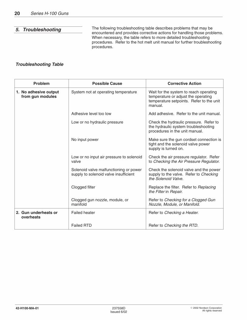
The following troubleshooting table describes problems that may beencountered and provides corrective actions for handling those problems.When necessary, the table refers to more detailed troubleshootingprocedures. Refer to the hot melt unit manual for further troubleshootingprocedures.
Problem Possible Cause Corrective Action
1. No adhesive outputfrom gun modules
System not at operating temperature Wait for the system to reach operatingtemperature or adjust the operatingtemperature setpoints. Refer to the unitmanual.
Adhesive level too low Add adhesive. Refer to the unit manual.
Low or no hydraulic pressure Check the hydraulic pressure. Refer tothe hydraulic system troubleshootingprocedures in the unit manual.
No input power Make sure the gun cordset connection istight and the solenoid valve powersupply is turned on.
Low or no input air pressure to solenoidvalve
Check the air pressure regulator. Referto Checking the Air Pressure Regulator.
Solenoid valve malfunctioning or powersupply to solenoid valve insufficient
Check the solenoid valve and the powersupply to the valve. Refer to Checkingthe Solenoid Valve.
Clogged filter Replace the filter. Refer to Replacingthe Filter in Repair.
Clogged gun nozzle, module, ormanifold
Refer to Checking for a Clogged GunNozzle, Module, or Manifold.
2. Gun underheats oroverheats
Failed heater Refer to Checking a Heater.
Failed RTD Refer to Checking the RTD.
5. Troubleshooting
Troubleshooting Table

Series H-100 Guns 21
� 2002 Nordson CorporationAll rights reserved
237558DIssued 6/02
42-H100-MA-01
1. Set the air pressure regulator to 0.
2. Turn off the air to the regulator at the air supply source.
3. Disconnect the solenoid valve air line from the regulator.
4. Restore air pressure to the regulator.
5. Gradually turn on the regulator to verify that air is flowing through it.
� No air flows from the regulator: regulator defective. Replace theregulator.
� Air flows from the regulator: normal indication. Return the airpressure to 0 and reconnect the air line to the regulator. Return tothe Troubleshooting Table.
The solenoid valve plug has a light that turns on when a trigger signal isreaching the valve.
1. Make sure the unit is at operating temperature and that the air supplyto the gun solenoid valve is turned on.
2. Manually activate the gun solenoid valve and check the light on theplug.
� Light turns on and gun fires: the trigger signal is reaching thesolenoid valve and the valve is functioning properly. Return to theTroubleshooting Table.
� Light does not turn on and gun fails to fire: Continue to the nextstep to check the power supply output voltage.
3. Remove the solenoid valve terminal block plug and use a voltmeter tocheck the power supply output voltage.
� 24 VDC being supplied: defective solenoid valve. Replace thesolenoid valve.
� Less than 24 VDC being supplied: power supply voltageinsufficient. Make sure the power supply is providing 24 VDC tothe solenoid valve.
Checking the Air PressureRegulator
Checking the Solenoid Valve

Series H-100 Guns22
� 2002 Nordson CorporationAll rights reserved
237558DIssued 6/02
42-H100-MA-01
WARNING: System or material pressurized. Relieve pressure.Failure to observe this warning can result in serious injury.
1. Turn off the pump and relieve system pressure. Refer to the unitmanual.
2. Turn off the gun air supply.
3. Place a drain pan below the gun.
4. Manually trigger the gun until it is drained of adhesive.
WARNING: Hot! Risk of burns. Wear heat-protective clothing,safety goggles, and heat-protective gloves.
5. Use a wrench to loosen the nozzle, then remove the nozzle by hand.Do not touch the needle.
6. Inspect the nozzle for blockage.
� Nozzle clogged: clean the nozzle. Refer to Cleaning Nozzles inRepair. Reinstall the nozzle on the gun and resume normaloperation.
� Nozzle not clogged: reinstall the nozzle on the gun and continueto the next step.
NOTE: If the spring-guide washer and seal-retaining spring fellout of the gun module when the nozzle was removed, reinstallthem in the orientation shown in Figure 5.
4293023A
1
2
3
Fig. 5 Orientation of Spring-Guide Washer and Seal Retaining Spring
1. Gun module2. Spring-guide washer
3. Seal-retaining spring
Checking for a Clogged GunNozzle, Module, or Manifold

Series H-100 Guns 23
� 2002 Nordson CorporationAll rights reserved
237558DIssued 6/02
42-H100-MA-01
WARNING: Hot! Risk of burns. Wear heat-protective clothing,safety goggles, and heat-protective gloves.
7. Remove the two socket-head screws that secure the gun module tothe gun manifold and remove the module.
8. Turn on the gun air supply.
9. Turn on the pump.
10. Trigger the gun by manually activating the solenoid valve.
� Adhesive flows from the gun manifold: module clogged. Replacethe module. Refer to Replacing a Gun Module in Repair.
� No adhesive flows from the gun manifold: the gun manifold isclogged or there is blockage in the hose or unit. If the gunmanifold is clogged, replace the gun. Refer to the unit manual forfurther hydraulic system troubleshooting procedures.

Series H-100 Guns24
� 2002 Nordson CorporationAll rights reserved
237558DIssued 6/02
42-H100-MA-01
WARNING: System or material pressurized. Relieve pressure.Failure to observe this warning may result in serious injury.
1. Turn off the pump and relieve system pressure. Refer to the unitmanual.
WARNING: Risk of equipment damage, personal injury, ordeath. Disconnect and lock out electrical power to the unit.
2. Turn off the unit; then disconnect and lock out electrical power to theunit.
3. Place a drain pan under the gun.
WARNING: Hot! Risk of burns. Wear heat-protective clothing,safety goggles, and heat-protective gloves.
4. Manually trigger the gun until it is drained of adhesive.
5. Turn off the gun air supply.
6. Unplug the gun cordset.
7. See Figure 6. Use a standard ohmmeter to check the heater circuit atthe cordset pins.
� Circuit not open: normal indication. Return to theTroubleshooting Table.
� Circuit open: loose connection between heater and cordset orfailed heater. Tighten the loose connection or replace the heateras appropriate. Refer to Replacing a Heater in Repair.
4201079
1
2
3
5
4
HEATER
HEATER
RTD
RTD
GND
5
4
2
3
1
RTD
Fig. 6 Typical Gun Cordset
Checking a Heater

Series H-100 Guns 25
� 2002 Nordson CorporationAll rights reserved
237558DIssued 6/02
42-H100-MA-01
WARNING: System or material pressurized. Relieve pressure.Failure to observe this warning may result in serious injury.
1. Turn off the pump and relieve system pressure. Refer to the unitmanual.
WARNING: Risk of equipment damage, personal injury, ordeath. Disconnect and lock out electrical power to the unit.
2. Turn off the unit; then disconnect and lock out electrical power to theunit.
3. Place a drain pan under the gun.
WARNING: Hot! Risk of burns. Wear heat-protective clothing,safety goggles, and heat-protective gloves.
4. Manually trigger the gun until it is drained of adhesive.
5. Turn off the gun air supply.
6. Wait until the gun reaches room temperature.
7. Unplug the gun cordset.
8. See Figure 6. Use an ohmmeter to measure the RTD resistance atthe cordset pins.
� See Figure 7. Resistance reading within appropriate range shownon chart: normal indication. Return to the Troubleshooting Table.
� Resistance reading not within appropriate range shown on chart:Failed RTD. Replace the RTD. Refer to Replacing the RTD inRepair.
NOTE: This is a reference check only. The indicated gun temperature,the gun surface temperature, and the RTD actual temperature can varyby over 15%. You must know the actual temperature of the RTD to usethe table.
Checking the RTD

Series H-100 Guns26
� 2002 Nordson CorporationAll rights reserved
237558DIssued 6/02
42-H100-MA-01
4207045
���
���
���
���
���
���
���
���
��
��
���
���
���
��
�
��
��
���
���
��
���
���
���
���
���
���
���
���
��
���
���
��
��
��
�
��
��
���
���
��
TEMPERATURE
TEMPERATURE
Fig. 7 RTD Resistance vs. RTD Temperature
Checking the RTD (contd.)

Series H-100 Guns 27
� 2002 Nordson CorporationAll rights reserved
237558DIssued 6/02
42-H100-MA-01
Troubleshooting contains diagnostic procedures which may identify failedcomponents. This section contains procedures for cleaning nozzles andfor replacing a gun module, heater, RTD, or manifold. Refer to Parts toorder replacement parts.
Follow this procedure to clean reduced-cavity nozzles.
WARNING: System or material pressurized. Relieve pressure.Failure to observe this warning may result in serious injury.
1. Turn off the pump and relieve system pressure. Refer to the unitmanual.
2. Turn off the unit.
3. Place a drain pan under all guns.
WARNING: Hot! Risk of burns. Wear heat-protective clothing,safety goggles, and heat-protective gloves.
4. Manually trigger the guns until they are drained of adhesive.
5. Turn off the gun air supply.
6. Turn off the solenoid valve power supply.
7. Use a wrench to loosen the nozzles; then remove the nozzles byhand. Do not touch the needle.
WARNING: Risk of personal injury or death. If heated above245 �C (475 �F), Type-R fluid can cause an explosion or a fire.Do not heat Type-R fluid with an open flame or in anunregulated heating device. Use a controlled heating device,such as a small deep-fat fryer or a thermostatically controlledhot plate.
8. Place the nozzles in a container of Type-R cleaning fluid.
9. Heat the cleaning fluid above the adhesive’s melting temperature, toa maximum of 177 �C (350 �F).
6. Repair
Cleaning Nozzles

Series H-100 Guns28
� 2002 Nordson CorporationAll rights reserved
237558DIssued 6/02
42-H100-MA-01
10. See Figure 8. Remove the nozzles from the cleaning fluid and cleanthem using a pin-type probe.
NOTE: Nordson Corporation offers a nozzle cleaning kit. Refer toParts.
4204026A
Fig. 8 Cleaning a Nozzle
11. Reinstall the nozzles on the guns and restore the system to normaloperation.
NOTE: If the spring-guide washer and seal-retaining spring fell out ofthe gun module when the nozzle was removed, reinstall them in theorientation shown in Figure 9.

Series H-100 Guns 29
� 2002 Nordson CorporationAll rights reserved
237558DIssued 6/02
42-H100-MA-01
4293023A
1
2
3
Fig. 9 Orientation of Spring-Guide Washer and Seal Retaining Spring
1. Gun module2. Spring-guide washer
3. Seal-retaining spring
Cleaning Nozzles (contd.)

Series H-100 Guns30
� 2002 Nordson CorporationAll rights reserved
237558DIssued 6/02
42-H100-MA-01
WARNING: System or material pressurized. Relieve pressure.Failure to observe this warning may result in serious injury.
1. Turn off the pump and relieve system pressure. Refer to the unitmanual.
WARNING: Risk of equipment damage, personal injury, ordeath. Disconnect and lock out electrical power to the unit.
2. Turn off the unit; then disconnect and lock out electrical power to theunit.
3. Place a drain pan under the gun.
WARNING: Hot! Risk of burns. Wear heat-protective clothing,safety goggles, and heat-protective gloves.
4. Manually trigger the gun until it is drained of adhesive.
5. Turn off the gun air supply.
6. Place a drain pan under the gun filter plug.
7. Use two wrenches to disconnect the hose from the gun. Place onewrench on the hose fitting and one on the gun fitting.
Replacing the Filter

Series H-100 Guns 31
� 2002 Nordson CorporationAll rights reserved
237558DIssued 6/02
42-H100-MA-01
8. See Figure 10. Unscrew the hose connector from the gun manifold.
9. Remove the filter (2) from the gun manifold (1) and insert a new filter.
4206037A
1 2 3
Fig. 10 Filter Components
1. Gun manifold2. Filter
3. Hose connector
10. Screw the hose connector back into the gun manifold. Tighten to0.55–0.68 N�m (5–6 ft-lb).
11. Reconnect the hose to the gun.
12. Restore the system to normal operation.

Series H-100 Guns32
� 2002 Nordson CorporationAll rights reserved
237558DIssued 6/02
42-H100-MA-01
On reduced-cavity guns, the nozzle is an integral part of the module.
WARNING: System or material pressurized. Relieve pressure.Failure to observe this warning may result in serious injury.
1. Turn off the pump and relieve system pressure. Refer to the unitmanual.
WARNING: Risk of equipment damage, personal injury, ordeath. Disconnect and lock out electrical power to the unit.
2. Turn off the unit; then disconnect and lock out electrical power to theunit.
3. Place a drain pan under the gun.
WARNING: Hot! Risk of burns. Wear heat-protective clothing,safety goggles, and heat-protective gloves.
4. Manually trigger the gun until it is drained of adhesive.
5. Turn off the gun air supply.
6. See Figure 11. Remove the two socket-head screws that secure thegun module to the gun manifold and remove the module.
4206040A
Fig. 11 Replacing a Gun Module
Replacing a Gun Module

Series H-100 Guns 33
� 2002 Nordson CorporationAll rights reserved
237558DIssued 6/02
42-H100-MA-01
7. Wipe off any adhesive on the gun manifold and check for adhesive inthe air supply ports.
CAUTION: Do not overtighten gun module screws. Doing socan permanantely damage the gun manifold.
8. Apply anti-seize lubricant to the gun module socket-head screws andsecure the new module to the gun manifold with the screws. Tightento 2.3 N�m (20 in.-lb).
NOTE: Because the gun module and manifold will expand whenheated, Nordson Corporation recommends retightening the gunmodule screws after initial heating of the gun. Do not overtighten thescrews. Doing so can permanently damage the gun manifold.
9. Restore the system to normal operation.
Follow this procedure to replace a gun heater. A gun may have one ortwo heaters.
WARNING: System or material pressurized. Relieve pressure.Failure to observe this warning may result in serious injury.
1. Turn off the pump and relieve system pressure. Refer to the unitmanual.
WARNING: Risk of equipment damage, personal injury, ordeath. Disconnect and lock out electrical power to the unit.
2. Turn off the unit; then disconnect and lock out electrical power to theunit.
3. Place a drain pan under the gun.
WARNING: Hot! Risk of burns. Wear heat-protective clothing,safety goggles, and heat-protective gloves.
4. Manually trigger the gun until it is drained of adhesive.
5. Turn off the gun air supply.
6. Unplug the gun cordset.
Replacing a Gun Module(contd.)
Replacing a Heater

Series H-100 Guns34
� 2002 Nordson CorporationAll rights reserved
237558DIssued 6/02
42-H100-MA-01
7. See Figure 12. Remove the gun manifold cover (1).
8. Remove the terminal block (2) and loosen the screws that secure theheater wires.
9. Remove and discard the defective heater (3).
4293021AH–104 90O
3
4
1
2
2
1
3
4
H–104
1
2
3
4
H–101
Fig. 12 Replacing a Heater or an RTD
1. Gun manifold cover2. Terminal block
3. Heater 4. RTD
Replacing a Heater (contd.)

Series H-100 Guns 35
� 2002 Nordson CorporationAll rights reserved
237558DIssued 6/02
42-H100-MA-01
10. Trim the heater wires to match the old heater wire length.
11. Strip about 6 mm (1/4 in.) of insulation from each wire.
12. See Figure 13. Insert an eyelet into each heater wire terminal blockopening; then insert the heater wires into the eyelets. If the gun hastwo heaters, two heater wires may be placed in the same eyelet.
4201081
4
1 2
31
5
Fig. 13 Gun Electrical Connections
1. Heater2. Terminal block3. Cordset
4. Ground wire5. RTD
13. Crimp the eyelets by tightening the terminal block screws. Tighten toapproximately 0.49 N�m (4.4 in.-lb).
14. Insert the new heater in the gun manifold.
15. Position the terminal block in the gun manifold, arranging the wiringso it will not be pinched when the gun manifold cover is secured.
16. Reposition and secure the gun manifold cover.
17. Plug the gun’s cordset into the hose plug receptacle.
18. Restore the system to normal operation.

Series H-100 Guns36
� 2002 Nordson CorporationAll rights reserved
237558DIssued 6/02
42-H100-MA-01
A new cordset must be installed when replacing the RTD.
WARNING: System or material pressurized. Relieve pressure.Failure to observe this warning may result in serious injury.
1. Turn off the pump and relieve system pressure. Refer to the unitmanual.
WARNING: Risk of equipment damage, personal injury, ordeath. Disconnect and lock out electrical power to the unit.
2. Turn off the unit; then disconnect and lock out electrical power to theunit.
3. Place a drain pan under the gun.
WARNING: Hot! Risk of burns. Wear heat-protective clothing,safety goggles, and heat-protective gloves.
4. Manually trigger the gun until it is drained of adhesive.
5. Turn off the gun air supply.
6. Unplug the gun cordset.
7. See Figure 12. Remove the gun manifold cover (1).
8. Remove the cordset wires from the terminal block (2) or blocks.
NOTE: Don’t remove the heater wires from the terminal block orblocks.
9. Disconnect the ground wire.
10. Unscrew the cordset locking nut and remove the cordset, includingthe RTD (4), from the gun.
NOTE: the cordset may screw directly into the gun manifold.
Replacing the RTD

Series H-100 Guns 37
� 2002 Nordson CorporationAll rights reserved
237558DIssued 6/02
42-H100-MA-01
11. Insert the new cordset wires through the gun manifold cover, thewasher, and the locking nut and tighten the locking nut.
NOTE: the cordset may screw directly into the gun manifold.
12. Insert the cordset wires in the terminal block or blocks and tighten theterminal block screws to approximately 0.49 N�m (4.4 in.-lb).
NOTE: Figure 13 shows the gun electrical connections.
13. Connect the ground wire.
14. Insert the RTD in the gun manifold.
15. Position the terminal block in the gun manifold, arranging the wiringso it will not be pinched when the gun manifold cover is secured.
16. Reposition and secure the gun manifold cover.
17. Plug the gun’s cordset into the hose plug receptacle.
18. Restore the system to normal operation.

Series H-100 Guns38
� 2002 Nordson CorporationAll rights reserved
237558DIssued 6/02
42-H100-MA-01
To order parts, contact the Nordson Customer Service Center or the localNordson representative. Use the following parts lists to describe andlocate parts correctly.
Numbers in the Item column correspond to numbers that identify parts inillustrations following each parts list. The code NS (not shown) indicatesthat a listed part is not illustrated. A dash (—) is used when the partnumber applies to all parts in the illustration.
The six-digit number in the Part column is the Nordson Corporation partnumber. A series of dashes in this column (- - - - - -) means the partcannot be ordered separately.
The Description column gives the part name, as well as its dimensionsand other characteristics when appropriate. Indentions show therelationships between assemblies, subassemblies, and parts.
Item Part Description Quantity Note
— 000 000 Assembly 1
1 000 000 � Subassembly 2 A
2 000 000 � � Part 1
� If ordering the assembly, items 1 and 2 will be included.� If ordering item 1, item 2 will be included.� If ordering item 2, only item 2 will be shipped.
The number in the Quantity column is the quantity required per unit,assembly, or subassembly. The code AR (As Required) is used if thepart number is a bulk item ordered in quantities or if the quantity perassembly depends on the product version or model.
Letters in the Note column refer to notes at the end of each parts list.Notes contain important information about usage and ordering. Specialattention should be given to notes.
7. Parts
Using the Illustrated Parts List

Series H-100 Guns 39
� 2002 Nordson CorporationAll rights reserved
237558DIssued 6/02
42-H100-MA-01
See Figure 14.
Item Part Description Quantity Note
1 771 129 Valve, solenoid, 400 Series, 1/8 BSPP 1
2 223 801 Cordset assembly w/RTD 1 A
3 939 586 Connector (terminal block), plastic, 2-station 1
4 271 598 Filter, 50 mesh 1
5 137 397 Heater, 240 VAC, 100 W, 0.25 in. X 1.19 in. 1 B
810 000 Heater, 240 VAC, 200 W, 0.38 in. X 1.5 in. 1 C
938 153 Heater, 240 VAC, 175 W, 0.375 in. X 1.75 in. 1 D
815 888 Heater, 240 VAC, 300 W, 0.371 in. X 3.25 in. 1 E
711 023 Heater, 240 VAC, 300 W, 0.38 in. X 4.00 in. 1 F
133 365 Heater, 120 VAC, 150 W, 0.38 in. X 1.5 in. 2 G
6 226 769 Service kit, eyelets 4 H
7 940 081 O-ring, Viton, 0.188 in. X 0.313 in. X 0.063 in. 3
8 309 921 Service kit, gun module, H-100 reduced-cavity,0.012 in. diameter
1 I
309 922 Service kit, gun module, H-100 reduced-cavity,0.016 in. diameter
1 I
309 923 Service kit, gun module, H-100 reduced-cavity,0.020 in. diameter
1 I
9 982 026 Screw, socket-head, M4 X 25 mm 2
NS 901 915 Nozzle cleaning kit —
NS 900 344 Anti-seize lubricant, 8 oz can —
NOTE A: Replacement cordset includes eyelets.
B: Use with H-101 guns.
C: Use with straight H-102 guns.
D: Use with 12� H-102 guns.
E: Use with straight and 12� H-104 guns.
F: Use with straight H-104 guns.
G: Use with 90� H-104 guns.
H: Includes 25 eyelets.
I: Includes three O-rings (item 7) and two screws (item 9).
NS: Not Shown
H-100 Gun Parts

Series H-100 Guns40
� 2002 Nordson CorporationAll rights reserved
237558DIssued 6/02
42-H100-MA-01
4293022A
2
1
3
4
5
6
78
9
Fig. 14 Series H-100 Gun Parts
H-100 Gun Parts (contd.)
