geotechnical design manual - oregon.gov · geotechnical design manual page 4 of 29 8 foundation...
TRANSCRIPT

GEOTECHNICAL DESIGN MANUAL CHAPTER 8- FOUNDATION DESIGN
GEO-ENVIRONMENTAL SECTION OREGON DEPARTMENT OF TRANSPORTATION
VERSION 2.0 6/1/2018

CHAPTER 8- FOUNDATION DESIGN
GEOTECHNICAL DESIGN MANUAL Page 2 of 29
TABLE OF CONTENTS SUMMARY OF CHANGES ............................................................................................................................... 3 8 FOUNDATION DESIGN ........................................................................................................................... 4
8.1 GENERAL ......................................................................................................................................................4 8.2 PROJECT DATA AND FOUNDATION DESIGN REQUIREMENTS .................................................................4 8.3 FIELD EXPLORATION FOR FOUNDATIONS .................................................................................................6 8.4 SAMPLING AND MATERIALS TESTING FOR FOUNDATIONS .....................................................................7 8.5 MATERIAL PROPERTIES FOR DESIGN .........................................................................................................8 8.6 BRIDGE APPROACH EMBANKMENTS ........................................................................................................8
8.6.1 ABUTMENT TRANSITIONS ......................................................................................................... 9 8.6.2 OVERALL STABILITY ................................................................................................................... 9
8.7 FOUNDATION SELECTION CRITERIA ....................................................................................................... 10 8.8 OVERVIEW OF LRFD FOR FOUNDATIONS............................................................................................... 12 8.9 FOUNDATION DESIGN POLICIES ............................................................................................................. 13
8.9.1 DOWNDRAG LOADS ................................................................................................................ 13 8.9.2 SCOUR DESIGN ........................................................................................................................ 13 8.9.3 SEISMIC DESIGN ...................................................................................................................... 14
8.10 SOIL LOADS ON BURIED STRUCTURES .................................................................................................... 15 8.11 SPREAD FOOTING DESIGN....................................................................................................................... 15
8.11.1 NEARBY STRUCTURES .......................................................................................................... 16 8.11.2 SERVICE LIMIT STATE DESIGN OF FOOTINGS ....................................................................... 16
8.12 DRIVEN PILE FOUNDATION DESIGN ....................................................................................................... 16 8.12.1 REQUIRED PILE TIP ELEVATION ............................................................................................ 17 8.12.2 PILE DRIVABILITY ANALYSIS AND WAVE EQUATION USAGE ................................................ 18 8.12.3 PILE SETUP AND RESTRIKE ................................................................................................... 18 8.12.4 DRIVEN PILE TYPES, AND SIZES ............................................................................................ 19 8.12.5 EXTREME EVENT LIMIT STATE DESIGN ................................................................................ 20
8.13 DRILLED SHAFT FOUNDATION DESIGN .................................................................................................. 23 8.13.1 DRILLED SHAFT BASE GROUTING ......................................................................................... 25 8.13.2 NEARBY STRUCTURES .......................................................................................................... 25 8.13.3 SCOUR .................................................................................................................................. 25 8.13.4 EXTREME EVENT LIMIT STATE DESIGN OF DRILLED SHAFTS ............................................... 25
8.14 MICROPILES .............................................................................................................................................. 26 8.15 REFERENCES ............................................................................................................................................. 27
APPENDIX .................................................................................................................................................... 29 LIST OF TABLES ...................................................................................................................................................... 29 LIST OF FIGURES .................................................................................................................................................... 29 LIST OF EQUATIONS .............................................................................................................................................. 29
CHAPTER 8- FOUNDATION DESIGN
GEOTECHNICAL DESIGN MANUAL Page 3 of 29
SUMMARY OF CHANGES
Chapter Summary of changes made Date revised
8 Updated All Chapter Content 3/28/2018

CHAPTER 8- FOUNDATION DESIGN
GEOTECHNICAL DESIGN MANUAL Page 4 of 29
8 FOUNDATION DESIGN 8.1 GENERAL
This chapter covers the geotechnical design of bridge foundations, retaining wall foundations and cut-and-cover tunnel foundations. Both shallow and deep foundation types are addressed. Foundation design work entails assembling all available foundation information for a structure, obtaining additional information as required, performing foundation analyses and compiling the information into a report that includes the specific structure foundation recommendations. An adequate site inspection, office study, appropriate subsurface exploration program and comprehensive foundation analyses that result in foundation recommendations are all necessary to construct a safe, cost-effective structure. See Chapter 21 for guidance on the foundation information that should be included in Geotechnical Reports. See Chapter 2 for guidance on foundation information available through office studies and the procedures for conducting a thorough site reconnaissance.
Unless otherwise stated in this manual, the Load and Resistance Factor Design approach (LRFD) shall be used for all foundation design projects, as prescribed in the most current version of the AASHTO (2014). The ODOT foundation design policies and standards described in this chapter supersede those in the AASHTO LRFD specifications. FHWA design manuals are also acceptable for use in foundation design and preferable in cases where foundation design guidance is not adequately provided in AASHTO. Structural design of bridge foundations, and other structure foundations, is addressed in the ODOT Bridge Design Manual (BDM).
It is important to establish and maintain close communication between the geotechnical designer and the structural designer at all times throughout the entire foundation design process and continuing through construction.
8.2 PROJECT DATA AND FOUNDATION DESIGN REQUIREMENTS
The scope of the project, project requirements, project constraints and the geology and subsurface conditions of the site should be analyzed to determine the type and quantity of geotechnical investigation work to be performed. Project information such as a vicinity map, a project narrative, preliminary structure plans/layout (pre-Type, Size & Location) and hydraulics information (if applicable) should be obtained to allow for proper planning of the subsurface exploration program. Keep abreast of changes to the project scope that might impact the geotechnical investigation and design work required. Proposed retaining wall and bridge bent locations should be obtained from the bridge designer prior to the beginning of field work to properly locate bore holes.
Anticipated foundation loads, structure settlement criteria and the heights of any proposed fills should be determined or estimated to insure that the exploration boreholes are advanced to the proper depth and the proper information is obtained.
Refer to AASHTO (2014), Article 10.4.1 for more details of the information needed at this stage.
The foundation type(s) selected for each structure will each require specific subsurface investigation methods, materials testing, analysis and design. Table 8.1 provides a summary of information needs and testing considerations for foundation design.

CHAPTER 8- FOUNDATION DESIGN
GEOTECHNICAL DESIGN MANUAL Page 5 of 29
Table 8.1 Summary of Information Needs and Testing Considerations (modified after Sabatini, et. al. 2002) Foundation
Type Engineering Evaluations
Required Information For Analyses
Field Testing
Laboratory Testing
Shallow Foundations
• bearing capacity • settlement
(magnitude & rate)
• shrink/swell of foundation soils (natural soils or embankment fill)
• frost heave • scour (for water
crossings) • liquefaction
• subsurface profile (soil, groundwater, rock)
• shear strength parameters • compressibility parameters
(including consolidation, shrink/swell potential, and elastic modulus)
• frost depth • stress history (present and
past vertical effective stresses)
• depth of seasonal moisture change
• unit weights • geologic mapping
including orientation and characteristics of rock discontinuities
• SPT (granular soils)
• CPT • PMT • dilatometer • rock coring
(RQD) • plate load
testing • geophysical
testing
• 1-D Oedometer tests
• soil/rock shear tests
• grain size distribution
• Atterberg Limits • specific gravity • moisture content • unit weight • organic content • collapse/ swell
potential tests • intact rock
modulus • point load strength
test
Driven Pile Foundations
• pile end-bearing • pile skin friction • settlement • down-drag on pile • lateral earth
pressures • chemical
compatibility of soil and pile
• drivability • presence of
boulders/very hard layers
• scour (for water crossings)
• vibration/heave damage to nearby structures
• liquefaction
• subsurface profile (soil, groundwater, rock)
• shear strength parameters • horizontal earth pressure
coefficients • interface friction
parameters (soil and pile) • compressibility parameters • chemical composition of
soil/rock (e.g., potential corrosion issues)
• unit weights • presence of shrink/swell
soils (limits skin friction) • geologic mapping
including orientation and characteristics of rock discontinuities
• SPT (granular soils)
• pile load test • CPT • PMT • vane shear
test • dilatometer • piezometers • rock coring
(RQD) • geophysical
testing
• soil/rock shear tests
• interface friction tests
• grain size distribution
• 1-D Oedometer tests
• pH, resistivity tests • Atterberg Limits • specific gravity • organic content • collapse/ swell
potential tests • intact rock
modulus • point load strength
test
Drilled Shaft Foundations
• shaft end bearing • shaft skin friction • constructability • down-drag on
shaft • quality of rock
socket • lateral earth
pressures • settlement
(magnitude &
• subsurface profile (soil, groundwater, rock)
• shear strength parameters • interface shear strength • friction parameters (soil
and shaft) • compressibility parameters • horizontal earth pressure
coefficients • chemical composition of
soil/rock
• installation technique test shaft
• shaft load test • vane shear
test • CPT • SPT (granular
soils) • PMT • dilatometer
• 1-D Oedometer tests
• soil/rock shear tests
• grain size distribution
• interface friction tests
• pH, resistivity tests • permeability tests • Atterberg Limits

CHAPTER 8- FOUNDATION DESIGN
GEOTECHNICAL DESIGN MANUAL Page 6 of 29
Foundation Type
Engineering Evaluations
Required Information For Analyses
Field Testing
Laboratory Testing
rate) • groundwater
seepage/ deep watering/ potential for caving
• presence of boulders/very hard layers
• scour (for water crossings)
• liquefaction
• unit weights • permeability of water-
bearing soils • presence of artesian
conditions • presence of shrink/swell
soils (limits skin friction) • geologic mapping
including orientation and characteristics of rock discontinuities
• degradation of soft rock in presence of water and/or air (e.g., rock sockets in shales)
• piezometers • rock coring
(RQD) • geophysical
testing
• specific gravity • moisture content • unit weight • organic content • collapse/ swell
potential tests • intact rock
modulus • point load strength
test • slake durability
8.3 FIELD EXPLORATION FOR FOUNDATIONS
Subsurface explorations shall be performed in accordance with Article 10.4.2 of the AASHTO (2014), supplemented by the FHWA Geotechnical Engineering Circular No. 5, “Evaluation of Soil and Rock Properties” (Sabatini, et. al., 2002). The procedures outlined in the ODOT “Soil and Rock Classification Manual” are used to describe and classify subsurface materials. The explorations shall provide the information needed for the design and construction of foundations. Accurate and adequate subsurface information at, or as near as possible to, each structure support is extremely important, especially for drilled shaft and spread footing designs.
The minimum exploration requirements specified in AASHTO (2014), Section 10, and as supplemented in Chapter 3, should be considered the standard of practice with regards to subsurface investigation requirements. It is understood that engineering judgment will need to be applied by a licensed and experienced geotechnical professional to adapt the exploration program to the foundation types and depths needed and to the variability in the subsurface conditions observed. The extent of exploration shall be based on the variability in the subsurface conditions, structure type, foundation loads, and any project requirements that may affect the foundation design or construction. The exploration program should be extensive enough to reveal the nature and types of soil deposits and/or rock formations encountered the engineering properties of the soils and/or rocks, the potential for liquefaction, and the groundwater conditions. The exploration program should be sufficient to identify and delineate problematic subsurface conditions such as deep, very soft soil deposits, bouldery deposits, swelling or collapsing soils, existing fill or waste areas, etc.
For cut-and-cover tunnels, culverts, arch pipes, etc., spacing of exploration locations shall be consistent with the requirements described in Chapter 3.
The groundwater conditions at the site are very important for both the design and construction of foundations. Groundwater conditions are especially important in the construction of drilled shafts, spread footings or any other excavation that might extend below the water table or otherwise encounter groundwater. Piezometer data adequate to define the limits and piezometric head in all unconfined, confined, and locally perched groundwater zones should be obtained at each foundation location. The measured depth and elevations of groundwater levels, and dates measured, should be noted on the exploration logs and discussed in the final Geotechnical Report. It is important to distinguish between the groundwater level and the level of any drilling fluid. Also, groundwater levels

CHAPTER 8- FOUNDATION DESIGN
GEOTECHNICAL DESIGN MANUAL Page 7 of 29
encountered during exploration may differ from design groundwater levels. Any artesian groundwater condition or other unusual groundwater condition should be identified and reported as this often has important impacts on foundation design and construction.
8.4 SAMPLING AND MATERIALS TESTING FOR FOUNDATIONS
Conduct subsurface investigations and materials testing in conformance with AASHTO (2014), Article 10.4. Table 8-1 provides a summary of field and laboratory testing considerations for foundation design. Foundation design will typically rely upon the Standard Penetration Test (SPT), Cone Penetrometer Test (CPT) and rock core samples obtained during the field exploration. Visual descriptions of the soil and rock materials are recorded. Correlations are usually made between these field tests to shear strength and compressibility of the soil. Groundwater and other hydraulic information needed for foundation design and constructability evaluation is typically obtained during the exploration using field instrumentation (e.g., piezometers) and in-situ tests (e.g., slug tests, pump tests, etc.).
ODOT owns the following equipment:
• Texam Pressuremeter which is available for use on Agency designed projects. The pressuremeter requires predrilled boreholes. The pressuremeter is stored in Region 2. Contact the Region 2 Bridge/Geo-Hydro Section for assistance in obtaining the use of this equipment.
• Vane Shear device, a Point Load Tester and a Geoprobe. Contact the Pavements Unit to schedule use of the Geoprobe equipment.
In general, for foundation design, laboratory testing should be used to augment the data obtained from the field investigation program and to refine the soil and rock properties selected for design. Index tests such as soil gradation, Atterberg limits, water content, and organic content are used to confirm the visual field classification of the soils encountered, but may also be used directly to obtain input parameters for some aspects of foundation design (e.g., soil liquefaction, scour, degree of over-consolidation, and correlation to shear strength or compressibility of cohesive soils). Laboratory tests conducted on undisturbed soil samples are used to assess shear strength or compressibility of finer grained soils, or to obtain seismic design input parameters such as shear modulus.
Soil Sampling and Testing for Steel Piling Corrosion Assessment
All steel piling used in permanent structure applications should be assessed for corrosion potential and designed for the long term effects of corrosion. ODOT BDDM Section 1.26.2 designates two distinct corrosive environments, Marine and Non-Marine, for steel pile corrosion assessment. Marine environments are located along the coast and generally require full corrosion protection systems, as described in BDDM 1.26.5. As such, Marine Environment sites generally do not require any soil or ground water sampling and testing, except as may be needed to verify soil conditions or for the design of corrosion protective systems. In Non-Marine environments, sampling and testing requirements for assessment of steel pile corrosion potential should generally follow the guidelines set forth in AASHTO Designation: R27-01 (AASHTO, 2010), “Standard of Practice for Assessment of Corrosion of Steel Piling for Non-Marine Applications”. The guidelines described in this document should be used as the basis, or framework, for developing a site-specific investigation and testing program for corrosion assessment and may be modified, depending on site conditions and other factors, so long as the corrosive potential of the site soils are adequately characterized. Research report NCHRP Report 408 (Beavers, J.A. and Durr, C.L., 1998), which was used as the basis for developing the AASHTO R27-01 standard, should also be referenced for the full background information on the corrosion evaluation process.

CHAPTER 8- FOUNDATION DESIGN
GEOTECHNICAL DESIGN MANUAL Page 8 of 29
At sites where there is no previous knowledge or information on the corrosive potential of foundation soils, surface (bulk) soil samples should be collected at proposed pile locations along with subsurface soil samples obtained from SPT split-spoons in conjunction with standard SPT sampling protocol, as described in Section 3.5.4. Samples may also be obtained from undisturbed (Shelby tube) samples or other sampling methods as needed to obtain representative samples of each distinct soil unit. The depth of soil sampling for corrosion testing should extend to either:
• 3 feet below the minimum ground water elevation, • top of bedrock or, • bottom of the test boring
Soil resistivity and pH testing is typically sufficient to characterize the corrosion potential of foundation soils in Non-Marine environments. No soil testing is required for piles that will be completely below the water table at all times. Soil samples from each distinct soil unit should be selected for pH and resistivity testing. For resistivity testing performed at the ODOT Materials Laboratory, a minimum sample size of at least 500 grams (about 1.1 lbs) is required. This may necessitate combining material from multiple SPT samples taken from the same soil unit together to provide sufficient material for testing. About 0.25 lbs (100 g) of soil is required for pH testing.
When soil resistivity is greater than 2000 ohm-cm and soil pH is greater than 5.5, no further evaluation is required and the steel piling may be designed with a minimal sacrificial steel thickness as described in the BDDM. Note that the pH criterion is 5.5, as per AASHTO (2014), and not 4.0 as per AASHTO R 27-01. If either test result does not meet the criteria, additional testing, consisting of chloride and sulfate ion content, should be conducted and the Bridge Engineering Section Corrosion Engineer and bridge design engineer should be consulted to evaluate the need for either corrosion protective systems or other alternatives.
8.5 MATERIAL PROPERTIES FOR DESIGN
The selection of soil and rock design properties should be in conformance with those described in Chapter 5 with additional reference to "Evaluation of Soil and Rock Properties”, Geotechnical Engineering Circular No. 5, (Sabatini, et al., 2002).
8.6 BRIDGE APPROACH EMBANKMENTS
The embankments at bridge ends should be evaluated for stability and settlement. The FHWA publication “Soils and Foundations Reference Manual”, (Samtani, 2006) should be referenced for guidance in the analysis and design of bridge approach embankments. New embankment placed for bridge approaches should be evaluated for short term (undrained) and long term (drained) conditions.
Bridge end slopes are typically designed at 2(H):1(V). If steeper end slopes such as 1½: 1 are desired, they should be evaluated for stability and designed to meet the required factors of safety. If embankment stability concerns arise, consider the use of staged construction, wick drains, flatter slopes, soil reinforcement, lightweight materials, sub excavation/replacement, counterbalances, or other measures depending on site conditions, costs and constraints. The embankment stability analysis, any recommended stabilization measures, instrumentation or other embankment monitoring needs, should be described in detail in the Geotechnical Report.
For overall stability, the static factor of safety for bridge approach embankments should be at least 1.30. A factor of safety of at least 1.5 must be provided against overall stability for abutment spread footings supported directly on embankments or abutment retaining walls. The program Slope/W is available for

CHAPTER 8- FOUNDATION DESIGN
GEOTECHNICAL DESIGN MANUAL Page 9 of 29
evaluating slope stability. Dynamic (seismic) slope stability, settlement and lateral displacements are discussed in Chapter 6.
The program “FoSSA” (Adama Engineering Inc., 2003) is available for use in assessing stresses and settlements under embankment and footings acting on horizontal ground surfaces. If the estimated post-construction settlement is excessive, consider the use of waiting periods, surcharges, wick drains or other ground improvement methods to expedite or minimize embankment settlement and allow for bridge construction. Consider relocating the bridge end if embankment settlement and stability concerns result in extreme and costly measures to facilitate embankment construction. Also, evaluate long term embankment settlement potential and possible down drag effects on piles or drilled shafts and provide down drag mitigation recommendations, such as wait periods, if necessary. In general, design for the long term settlement of approach embankments to not exceed 1” in 20 years. Refer to the ODOT BDDM for additional approach fill settlement limitations regarding integral abutments.
8.6.1 ABUTMENT TRANSITIONS ODOT standard practice is to provide bridge end panels at each end bent location for bridges constructed on the State Highway system. Embankment settlement often occurs at this transition point after construction is completed and the end panels are necessary to eliminate a potentially dangerous traffic hazard and reduce the impact of traffic loads to the bridge. The settlement is sometimes the result of poorly placed and compacted abutment backfill or might be due to long-term settlement of the foundation soils. Guidance for proper detailing and material requirements for abutment backfill is provided in the "Soils and Foundations Reference Manuals, Volumes 1 & 2”, (Samtani, 2006).
End panels may be considered for deletion if the following geotechnical conditions are met:
• Foundation materials are characterized as “incompressible” (e.g., bedrock or very dense granular soils)
• Post-construction settlement estimates are negligible (<0.25”) • Provisions are made to insure the specifications for embankment and backfill materials,
placement and compaction are adhered to (increased inspection and testing QC/QA)
Deletion of end panels requires a geotechnical and structural evaluation and approval of a deviation from standard ODOT BDDM practice. The final decision on whether or not to delete end panels shall be made by the ODOT HQ Bridge Engineering Section Engineer with consideration to the geotechnical and structural evaluation.
In addition to geotechnical criteria, other issues such as average daily traffic (ADT), design speed, or accommodation of certain bridge structure details may supersede the geotechnical reasons for deleting end panels. End panels shall be used for all ODOT bridges with stub, or integral abutments to accommodate bridge expansion and contraction. End panels shall also be used in all cases where seismic loads could result in excessive dynamic fill settlement and the failure to meet the performance criteria described in the BDDM.
8.6.2 OVERALL STABILITY The evaluation of overall stability of earth slopes with or without a foundation unit shall be investigated at the service limit state as specified in Article 11.6.2.3 of the AASHTO (2014). Overall stability should be evaluated using limiting equilibrium methods such as modified Bishop, Janbu, Spencer, or other widely accepted slope stability analysis methods. Article 11.6.2.3 recommends that overall stability be evaluated at the Service I limit state (i.e., a load factor of 1.0) and a resistance factor, φos, of 0.65 for slopes which support a structural element. This corresponds to a factor of safety of 1.5.
CHAPTER 8- FOUNDATION DESIGN
GEOTECHNICAL DESIGN MANUAL Page 10 of 29
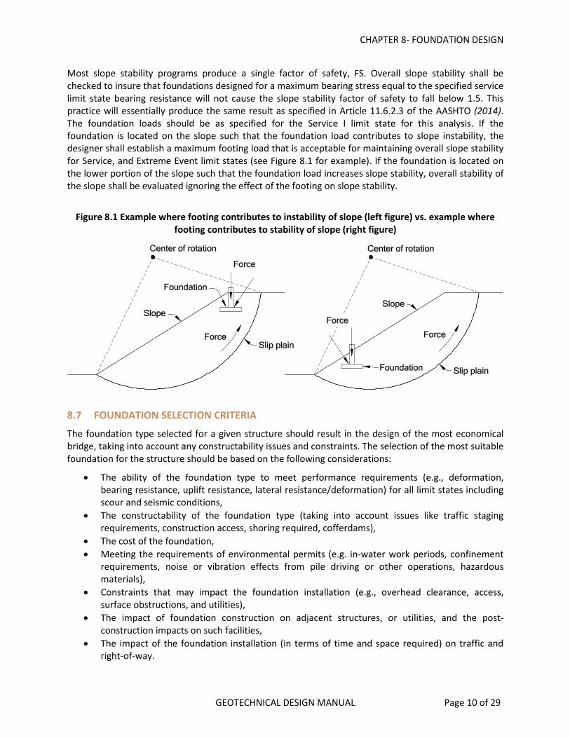
Most slope stability programs produce a single factor of safety, FS. Overall slope stability shall be checked to insure that foundations designed for a maximum bearing stress equal to the specified service limit state bearing resistance will not cause the slope stability factor of safety to fall below 1.5. This practice will essentially produce the same result as specified in Article 11.6.2.3 of the AASHTO (2014). The foundation loads should be as specified for the Service I limit state for this analysis. If the foundation is located on the slope such that the foundation load contributes to slope instability, the designer shall establish a maximum footing load that is acceptable for maintaining overall slope stability for Service, and Extreme Event limit states (see Figure 8.1 for example). If the foundation is located on the lower portion of the slope such that the foundation load increases slope stability, overall stability of the slope shall be evaluated ignoring the effect of the footing on slope stability.
Figure 8.1 Example where footing contributes to instability of slope (left figure) vs. example where
footing contributes to stability of slope (right figure)
8.7 FOUNDATION SELECTION CRITERIA
The foundation type selected for a given structure should result in the design of the most economical bridge, taking into account any constructability issues and constraints. The selection of the most suitable foundation for the structure should be based on the following considerations:
• The ability of the foundation type to meet performance requirements (e.g., deformation, bearing resistance, uplift resistance, lateral resistance/deformation) for all limit states including scour and seismic conditions,
• The constructability of the foundation type (taking into account issues like traffic staging requirements, construction access, shoring required, cofferdams),
• The cost of the foundation, • Meeting the requirements of environmental permits (e.g. in-water work periods, confinement
requirements, noise or vibration effects from pile driving or other operations, hazardous materials),
• Constraints that may impact the foundation installation (e.g., overhead clearance, access, surface obstructions, and utilities),
• The impact of foundation construction on adjacent structures, or utilities, and the post-construction impacts on such facilities,
• The impact of the foundation installation (in terms of time and space required) on traffic and right-of-way.

CHAPTER 8- FOUNDATION DESIGN
GEOTECHNICAL DESIGN MANUAL Page 11 of 29
This is the most important step in the foundation design process. These considerations should be discussed (as applicable) with the structural designer. Bridge bent locations may need to be adjusted based on the foundation conditions, construction access or other factors described above to arrive at the most economical and appropriate design.
Spread Footings
Spread footings are typically very cost effective, given the right set of conditions. Footings work best in hard or dense soils that have adequate bearing resistance and exhibit tolerable settlement under load. Footings can get rather large in less dense soils such as medium dense sand or stiff clays depending on the structure loads and settlement requirements. Structures with tall columns or with high lateral loads which result in large eccentricities and footing uplift loads may not be suitable candidates for footing designs. Footings are not allowed or cost-effective where soil liquefaction can occur at or below the footing level. Other factors that affect the cost feasibility of spread footings include:
• The need for a cofferdam and seals when placed below the water table, • The need for significant over-excavation and replacement of unsuitable soils, • The need to place footings deep due to scour, liquefaction or other conditions, • The need for significant shoring to protect adjacent existing facilities, and • Inadequate overall stability when placed on slopes that have marginally adequate stability.
Settlement (service limit state criteria) often controls the feasibility of spread footings. The amount of footing settlement must be compatible with the overall bridge design. The superstructure type and span lengths usually dictate the amount of settlement the structure can tolerate and footings may still be feasible and cost effective if the structure can be designed to tolerate the estimated settlement (e.g., flat slab bridges, bridges with jackable abutments, etc.). Footings may not be feasible where expansive or collapsible soils are present near the bearing elevation. Refer to the FHWA Geotechnical Engineering Circular No. 6, Shallow Foundations (Kimmerling, 2002), and the FHWA publication, Selection of Spread Footings on Soils to Support Highway Bridge Structures (Samatini, 2010) for additional guidance on the selection and use of spread footings.
Deep Foundations
Deep foundations are the next choice when spread footings cannot be founded on competent soils or rock at a reasonable cost. Deep foundations are also required at locations where footings are unfeasible due to extensive scour depths, liquefaction or lateral spread problems. Deep foundations may be installed to depths below these susceptible soils to provide adequate foundation resistance and protection against these problems. Deep foundations should also be used where an unacceptable amount of spread footing settlement may occur. Deep foundations should be used where right-of-way, space limitations, or other constraints as discussed above would not allow the use of spread footings.
The two types of deep foundations most typically considered are: pile foundations, and drilled shaft foundations. The most economical deep foundation alternative should be selected unless there are other controlling factors. Shaft foundations are most advantageous where very dense intermediate strata must be penetrated to obtain the desired bearing, uplift, or lateral resistance, or where materials such as boulders or logs must be penetrated. Shafts are often cost effective where a single shaft per column can be used in lieu of a pile group with a pile cap, especially when a cofferdam, seal and/or shoring is required to construct the pile foundation and pile cap. Shafts are also sometimes used in lieu of piles where pile driving vibrations could cause damage to existing adjacent facilities or in situations where pile driving is restricted due to environmental regulations.

CHAPTER 8- FOUNDATION DESIGN
GEOTECHNICAL DESIGN MANUAL Page 12 of 29
Shafts may not be desirable where contaminated soils are present, since the contaminated soil removed would require special handling and disposal. Constructability is also an important consideration in the selection of drilled shafts. For instance, artesian water pressure in subsurface soil layers could also preclude the use of drilled shafts due to the difficulty in maintaining stability of the shaft excavation.
When designing pile foundations keep in mind the potential cost impacts associated with the use of large pile hammers. Local pile driving contractors own hammers with rated energies typically ranging up to about 80,000 ft.-lbs. When larger hammers are required to drive piles to higher pile bearing resistance they have to rent the hammers and the mobilization cost associated with furnishing pile driving equipment may increase sharply. Larger hammers may also impact the design and cost work bridges due to higher hammer and crane loads.
For situations where existing substructures must be retrofitted to improve foundation resistance, where there is limited headroom available for pile driving or shaft construction, or where large amounts of boulders or obstructions must be penetrated, micropiles may be the best foundation alternative, and should be considered.
Augercast piles can be very cost effective in certain situations. However, they present significant challenges with respect to verifying integrity and capacity. Therefore, it is ODOT current policy not to use augercast piles for bridge foundations.
8.8 OVERVIEW OF LRFD FOR FOUNDATIONS
The basic equation for load and resistance factor design (LRFD) states that the loads multiplied by factors to account for uncertainty, ductility, importance, and redundancy must be less than or equal to the available resistance multiplied by factors to account for variability and uncertainty in the resistance per the AASHTO (2014). The basic equation, therefore, is as follows:
Equation 8.1
Σηιγi Qi ≤ ϕRn
ηι = Factor for ductility, redundancy, and importance of structure
γi = Load factor applicable to the i’th load Qi
Qi = Load
Φ = Resistance factor
Rn = Nominal (predicted) resistance
For typical ODOT practice, ηι is set equal to 1.0 for use of both minimum and maximum load factors.
The product, ϕRn, is termed the “factored resistance”. This term is analogous to the term “allowable capacity” previously used in Allowable Stress Design. AASHTO Article 10.5.5 provides the resistance factors to use in foundation design. Resistance factors for a given foundation type are a function of the design method used, soil type/condition and other factors. AASHTO Article 10.5.5, and its associated commentary, should be reviewed for information on the development of the specified resistance factors used in foundation design and provides guidance in the selection and use of these factors. Foundations shall be proportioned so that the factored resistance is always greater than or equal to the factored loads. The loads and load factors to be used in pile foundation design shall be as specified in Section 3 of the AASHTO (2014).
CHAPTER 8- FOUNDATION DESIGN
GEOTECHNICAL DESIGN MANUAL Page 13 of 29
8.9 FOUNDATION DESIGN POLICIES
8.9.1 DOWNDRAG LOADS Downdrag loads on piles, shafts, or other deep foundations shall be evaluated as described in AASHTO (2014), Section 3. If a downdrag condition exists, the resulting downdrag loads are included with the permanent load combinations used in structure design and an appropriate load factor is applied to the downdrag loads. In addition to applying the downdrag loads on the load side of the LRFD equation, the downdrag loads must also be subtracted from the resistance side of the equation since this resistance will not be available for foundation support.
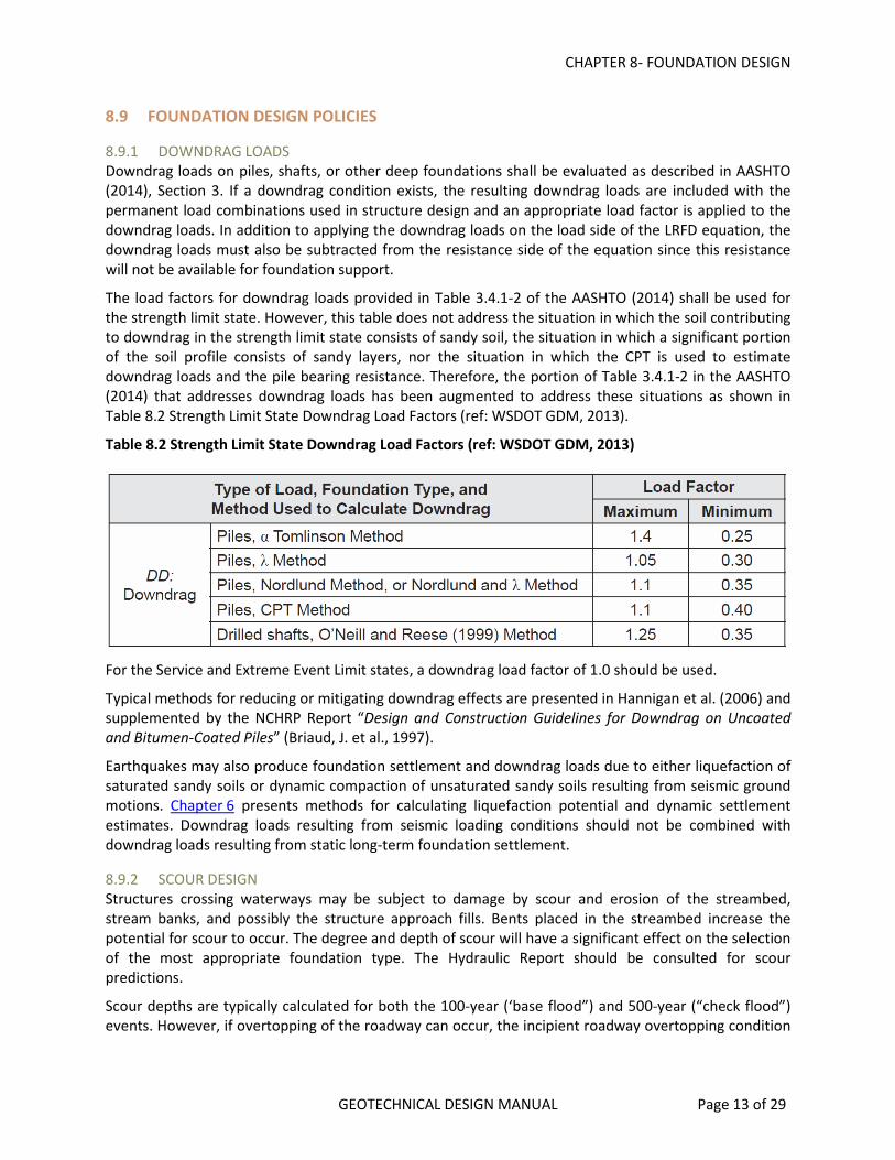
The load factors for downdrag loads provided in Table 3.4.1-2 of the AASHTO (2014) shall be used for the strength limit state. However, this table does not address the situation in which the soil contributing to downdrag in the strength limit state consists of sandy soil, the situation in which a significant portion of the soil profile consists of sandy layers, nor the situation in which the CPT is used to estimate downdrag loads and the pile bearing resistance. Therefore, the portion of Table 3.4.1-2 in the AASHTO (2014) that addresses downdrag loads has been augmented to address these situations as shown in Table 8.2 Strength Limit State Downdrag Load Factors (ref: WSDOT GDM, 2013).
Table 8.2 Strength Limit State Downdrag Load Factors (ref: WSDOT GDM, 2013)
For the Service and Extreme Event Limit states, a downdrag load factor of 1.0 should be used.
Typical methods for reducing or mitigating downdrag effects are presented in Hannigan et al. (2006) and supplemented by the NCHRP Report “Design and Construction Guidelines for Downdrag on Uncoated and Bitumen-Coated Piles” (Briaud, J. et al., 1997).
Earthquakes may also produce foundation settlement and downdrag loads due to either liquefaction of saturated sandy soils or dynamic compaction of unsaturated sandy soils resulting from seismic ground motions. Chapter 6 presents methods for calculating liquefaction potential and dynamic settlement estimates. Downdrag loads resulting from seismic loading conditions should not be combined with downdrag loads resulting from static long-term foundation settlement.
8.9.2 SCOUR DESIGN Structures crossing waterways may be subject to damage by scour and erosion of the streambed, stream banks, and possibly the structure approach fills. Bents placed in the streambed increase the potential for scour to occur. The degree and depth of scour will have a significant effect on the selection of the most appropriate foundation type. The Hydraulic Report should be consulted for scour predictions.
Scour depths are typically calculated for both the 100-year (‘base flood”) and 500-year (“check flood”) events. However, if overtopping of the roadway can occur, the incipient roadway overtopping condition

CHAPTER 8- FOUNDATION DESIGN
GEOTECHNICAL DESIGN MANUAL Page 14 of 29
is then the worst case for scour because it will usually create the greatest flow contraction and highest water velocities at the bridge. This overtopping condition may occur less than every 100 years and therefore over-ride the base flood (100-yr) design condition or it could occur between 100 and 500 year floods and over-ride the 500-year (check flood) condition. Therefore, scour depths are calculated depending on the recurrence interval for the overtopping flood. See Chapter 10 of the ODOT Hydraulics Manual for a description of these specific conditions and criteria. The Hydraulics Report will provide the scour elevations for each of these conditions.
The tops of footings should be set below the potential scour elevation for the 100-year flood or the roadway-overtopping flood, whichever is the deepest. The bottom of the footing should be set below the potential scour elevation for the Check Flood, which will be either the roadway-overtopping flood or the 500-year flood.
Foundation design for the scour condition associated with the base flood (typ. 100-yr. event) is the same as the “no-scour” condition. Factored foundation resistances must be adequate to resist the factored loads associated with the strength and service limit states (AASHTO (2014), Article 3.7.5). For the check flood condition the foundations must provide nominal bearing resistances (resistance factor equal to 1.0) sufficient to support the structure loads associated with the Extreme Limit State (AASHTO (2014), Article 10.5.5.3.2).
For footings constructed on bedrock, provide recommendations regarding the scour potential of the bedrock to the Hydraulics designer. Some types of “bedrock” are very weak and extremely susceptible to erosion and scour. At present, there are limited specific recommendations or guidelines to use to determine the scour potential of bedrock types typically found in Oregon. Refer to “Evaluating Scour at Bridges” (Arneson et al., 2012) for additional guidance in predicting the scour potential of rock. Engineering judgment should be used in estimating the scour potential of marginally “good” quality rock, taking into account rock strength, RQD, joint spacing, joint filling material, open fractures, weathering, degradation characteristics and other factors. See if any exposed bedrock at the site shows signs of erosion or degradation or if there is a history of bedrock scour in the past. Signs of bedrock scour may include the undermining of existing footings, steeply incised stream banks or scour holes in the bedrock streambed. If any doubts remain, drilled shafts should be considered.
Refer to the ODOT Hydraulics Manual for more guidance regarding scour, riprap protection and footing depth requirements. Loose riprap, placed at interior (in-water) pier locations, is not considered permanent protection. Design riprap protected abutments according to the guidance and recommendations outlined in FHWA HEC-18 manual, “Evaluating Scour at Bridges” (Arneson et al., 2012).
Bridge approach embankments may also be vulnerable to partial or complete removal (or “washout”) when located in areas with certain hydrologic settings. Partial or complete washout of embankment material behind and beneath bridge abutments could lead to unbalanced, and destabilizing, bridge loads which must be evaluated. The potential for washout conditions should be addressed in the Bridge Hydraulic Report. Refer to ODOT BDM Section 3.14.7 for requirements and guidelines regarding bridge washout evaluations.
8.9.3 SEISMIC DESIGN Chapter 6 describes ODOT seismic foundation design practices regarding design criteria, performance requirements, ground motion characterization, liquefaction analysis, ground deformation and mitigation. The most current edition of the “AASHTO Guide Specifications for LRFD Seismic Bridge Design” (AASHTO, 2011), including the latest interims, should be used for seismic foundation design.

CHAPTER 8- FOUNDATION DESIGN
GEOTECHNICAL DESIGN MANUAL Page 15 of 29
Once the seismic analysis is performed the results are applied to foundation design in the Extreme Event I limit state analysis as described in Section 10 of the AASHTO (2014). Also refer to, and be familiar with,
Section 1.10.4; “Foundation Modeling”, of the ODOT Bridge Design Manual. This section describes the various methods bridge designers use to model the response of bridge foundations to seismic loading and also the geotechnical information required to perform the analysis.
In general, nominal resistances are used in seismic design except for pile and shaft uplift conditions (see AASHTO (2014), Article 10.5.5.3).
If the foundation soils are determined to be susceptible to liquefaction, then spread footings should not be recommended for foundation support of the structure unless proven ground improvement techniques are employed to stabilize the foundation soils and eliminate the liquefaction potential. Otherwise, a deep foundation should be recommended.
Deep foundations (piles and drilled shafts) supporting structures that are constructed on potentially liquefiable soils are normally structurally checked for two separate loading conditions; i.e. with and without liquefaction. Nominal resistances, factored resistances (as appropriate), downdrag loads (if applicable) and soil (p-y) interaction parameters should be provided for both non-liquefied and liquefied foundation conditions. Communication with the structural designer is necessary to insure that the proper foundation design information is provided.
If the predicted amount of earthquake-induced embankment deformation (lateral deformation and/or settlement) is excessive then assessments should be made of approach fill performance and the potential for bridge and approach fill damage. The need for possible liquefaction mitigation measures should then be evaluated. Refer to the ODOT Liquefaction Mitigation Procedures described in Chapter 6.
8.10 SOIL LOADS ON BURIED STRUCTURES
For tunnels, culverts and pipe arches, the soil loads to be used for design shall be as specified in Sections 3 and 12 of the AASHTO (2014).
8.11 SPREAD FOOTING DESIGN
Refer to AASHTO LRFD Bridge Design Specification, Article 10.6 for spread footing design requirements and supporting FHWA documents by Kimmerling (2002) and Gifford, et al. (1987).
Once footings are selected as the preferred design alternative, the general spread footing foundation design process can be summarized as follows. Close communication and interaction is required between the structural and geotechnical designers throughout the footing design phase.
• Determine footing elevation based on location of suitable bearing stratum and footing dimensions (taking into account any scour requirements, if applicable)
• Determine foundation material design parameters and groundwater conditions • Calculate the nominal bearing resistance for various footing dimensions (consult with structural
designer for suitable dimensions) • Select resistance factors depending on design method(s) used; apply them to calculated nominal
resistances to determine factored resistances • Determine nominal bearing resistance at the service limit state • Check overall stability (determine max. bearing load that maintains adequate slope stability)
For footings located in waterways, the bottom of the footing should be below the estimated depth of scour for the check flood (typically the 500 year flood event or the overtopping flood). The top of the footing should be below the depth of scour estimated for the design flood (either the overtopping or

CHAPTER 8- FOUNDATION DESIGN
GEOTECHNICAL DESIGN MANUAL Page 16 of 29
100-year event). As a minimum, the bottom of all spread footings should also be at least 6 feet below the lowest streambed elevation unless they are keyed full depth into bedrock that is judged not to erode over the life of the structure. Spread footings are not permitted on soils that are predicted to liquefy under the design seismic event.
8.11.1 NEARBY STRUCTURES Refer to AASHTO (2014), Article 10.6.1.8. Issues to be investigated include, but are not limit to, settlement of the existing structure due to the stress increase caused by the new footing, decreased overall stability due to the additional load created by the new footing, and the effect on the existing structure of excavation, shoring, and/or dewatering to construct the new foundation.
8.11.2 SERVICE LIMIT STATE DESIGN OF FOOTINGS Footing foundations shall be designed at the service limit state to meet the tolerable movements for the structure in accordance with AASHTO (2014), Article 10.5.2. Consult with the bridge designer to obtain the maximum total and differential foundation settlements allowed for the proposed structure. The nominal unit bearing resistance at the service limit state shall be equal to or less than the maximum bearing stress that results in settlement that meets the tolerable movement criteria for the structure.
8.12 DRIVEN PILE FOUNDATION DESIGN
Refer to AASHTO (2014), Article 10.7 for pile design requirements. The FHWA publication “Design and Construction of Driven Pile Foundations” (Hannigan et al., 2006) may also be referenced for driven pile design guidance although this manual does not follow the LRFD approach, as required by ODOT. Pile design should meet or exceed the requirements specified for each limit state. ODOT standards and policies regarding pile foundation design and construction shall also be followed.
The nominal bearing resistance of all driven piles shall be accepted based on either the FHWA Gates Equation, wave equation analysis, dynamic measurements with signal matching (PDA/CAPWAP) or full-scale load testing. Acceptance of driven piles shall not be accepted based solely on static analysis.
For piles requiring relatively low nominal resistances (<600 kips) and without concerns about high driving stresses, the FHWA Gates Equation is typically used for determining pile driving acceptance criteria. In cases where piles are driven to higher resistances or where high pile driving stresses are a concern, such as short, end bearing piles, the wave equation (GRLWEAP) is typically used for both drivability analysis and in determining the final driving acceptance criteria.
Pile acceptance based on the pile driving analyzer (PDA) is typically reserved for projects where it is economically advantageous to use, or for cases where high pile driving stresses are predicted and require monitoring. The PDA (with signal matching) method can be most cost effective on projects that have a large number of long, high capacity, friction piles.
Full-scale static pile load tests are less common in practice due to their inherent expense. However, they may be economically justified in cases where higher bearing resistances can be verified through load testing and applied in design to reduce the cost of the pile foundation. If static load testing is considered for a project it should be conducted early on in the design stage so the results may be utilized in the design of the structure. Also, the pile load test should be taken to complete failure if at
all possible. Refer to AASHTO (2014), Section 10 for descriptions on how to use the results of the static load tests results to determine driving criteria. Static load test results should be used in combination with either PDA/CAPWAP testing or wave equation analysis to develop final driving criteria for the production piles.

CHAPTER 8- FOUNDATION DESIGN
GEOTECHNICAL DESIGN MANUAL Page 17 of 29
Once the pile (bent) locations and foundation materials and properties are defined, the pile foundation design process for normal bridge projects typically consists of the following:
• Determine scour depths (if applicable) • Determine liquefaction potential and depths; estimate seismic induced settlement (if applicable) • Evaluate long-term embankment settlement and downdrag potential • Select most appropriate pile type • Select pile dimension (size) based on discussions with structural designer regarding preliminary
pile loading requirements (axial and lateral) • Establish structural nominal resistance of the selected pile(s) • Conduct static analysis to calculate nominal single pile resistance as a function of depth for the
strength and extreme limit states (or a pile length for a specified resistance) • Select resistance factors based on the field method to be used for pile acceptance (e.g. dynamic
formula (FHWA Gates Equation), wave equation, PDA/CAPWAP, etc.) • Calculate single pile factored resistance as a function of depth • Estimate downdrag loads; consolidation and/or seismic-induced (if applicable) • Calculate pile/pile group settlement or pile lengths required to preclude excessive settlement • Determine nominal (and factored) uplift resistance as a function of depth • Determine p-y curve parameters for lateral load analysis • Modify parameters for liquefied soils (if applicable) • Provide P-multipliers as appropriate for pile groups. P-multipliers are not required for pile (or
shafts) groups installed in rock sockets where calculated lateral displacements are minimal (i.e., <0.50”).
• Determine required pile tip elevation(s) based on structural and geotechnical design requirements including the effects of scour, downdrag, or liquefaction
• Obtain and verify final pile tip elevations and required resistances (to resist factored and unfactored loads) from the structural designer; finalize required pile tip elevations and assess the following: - Determine the need to perform a pile drivability analysis to obtain required tip elevation - Evaluate pile group settlement (if applicable). If settlement exceeds allowable criteria,
adjust pile lengths or the size of the pile layout and/or lengths • Determine the need for pile tip reinforcement
8.12.1 REQUIRED PILE TIP ELEVATION Required pile tip elevations should typically be provided for all pile foundation design projects. The required pile tip elevation is provided to ensure the constructed foundation meets the design requirements of the project, which may include any or all of the following conditions and criteria:
• Pile tip reaches the designated bearing layer • Scour • Downdrag • Uplift • Lateral loads
A general note is included on the bridge plans designating the “Pile Tip Elevation for Minimum Penetration” for each bent.
The required tip elevation may require driving into, or through, very dense soil layers resulting in potentially high driving stresses. Under these conditions a wave equation drivability analysis is necessary

CHAPTER 8- FOUNDATION DESIGN
GEOTECHNICAL DESIGN MANUAL Page 18 of 29
to make sure the piles can be driven to the required embedment depth (tip elevation). Higher grade steel (ASTM A252, Grade 3 or A572, Grade 50) are sometimes specified if needed to meet drivability criteria. If during the structural design process, adjustments in the required tip elevations are necessary, or if changes in the pile diameter are necessary, the geotechnical designer should be informed so that pile drivability can be re-evaluated.
8.12.2 PILE DRIVABILITY ANALYSIS AND WAVE EQUATION USAGE High pile stresses often occur during pile driving operations and, depending on subsurface and loading conditions, a Wave Equation analysis should always be considered to evaluate driving stresses and the possibility of pile damage. A pile drivability analysis is typically used in most pile foundation designs to determine the nominal geotechnical resistance that a pile can be driven to without damage. Foundation piles should typically be driven to the highest geotechnical axial resistance feasible based on wave equation analysis so the maximum structural resistance of the pile is utilized, resulting in the most cost-effective pile design.
All piles driven to nominal resistances greater than 600 kips should be driven based on wave equation criteria. Piles driven to nominal resistance less than or equal to 600 kips may also require a wave equation analysis depending on the subsurface conditions (such as very short end bearing piles) and the pile loads. Engineering judgment is required in this determination. It is also advantageous to use the wave equation method to verify pile resistance because of the higher resistance factor (0.50) that can be used versus the FHWA Gates Equation factor of 0.40. Pile driving stresses should be limited to those described in AASHTO (2014), Article 10.7.8.
8.12.3 PILE SETUP AND RESTRIKE Using a waiting period and restrike after initial pile driving may be advantageous in certain soil conditions to optimize pile foundation design. After initially driving the piles to a specified tip elevation, the piles are allowed to “set up” for a specified waiting period, which allows pore water pressures to dissipate and soil strength to increase. The piles are then re-struck to confirm the required nominal resistance.
The length of the waiting period depends primarily on the strength and drainage characteristics of the subsurface soils (how quickly the soil can drain) and the required nominal resistance. The minimum waiting period specified in the Standard Specifications is 24 hours. If needed, this waiting period may be extended in the contract special provisions to provide additional time for the soils to gain strength and the piles to gain resistance. However, consideration should be given to increased contractor standby costs that may be incurred by extended waiting periods. The pile design should compare the cost and risk of extending the standard waiting period to gain sufficient strength versus designing and driving the piles deeper to achieve the required bearing.
For projects with piles that require restrike, at least 2 piles per bent or 1 in 10 piles in a group (whichever is more) should typically be re-struck for pile acceptance. Additional restrike verification testing should be conducted on any piles that indicate lower resistance at the end of initial driving or if subsurface conditions vary substantially within a pile group. Restrike should be performed using a warm pile hammer, which has been warmed up with at least 20 blows on another pile.
Restrike resistance (blows per inch) should be determined by measuring the total pile set in the first 5 blows of driving and in successive 5 blow increments thereafter up to a total of at least 20 blows or until refusal driving conditions are reached (>20 blows per inch). The driving resistance reported (in blows per inch) is then determined by taking the inverse of the set (inches/blow) per each 5 blow increment. The hammer stroke during the restrike should also be carefully measured and recorded since this is use in

CHAPTER 8- FOUNDATION DESIGN
GEOTECHNICAL DESIGN MANUAL Page 19 of 29
combination with the driving resistance (bpi) to determine the nominal pile resistance when using either the FHWA Gates formula or from wave equation criteria.
8.12.4 DRIVEN PILE TYPES, AND SIZES The pile types generally used on most permanent structures are steel pipe piles (driven either open or closed-end) and steel H-piles. Either H-pile or open-end steel pipe pile can be used for end bearing conditions. For friction piles, steel pipe piles are often preferred because they can be driven closed-end (as full displacement piles) and because of their uniform cross section properties, which provides the same structural bending resistance in any direction of loading. This is especially helpful under seismic loading conditions where the actual direction of lateral loading is not precisely known. Uniform section properties of steel pipe piles also aid in pile driving. Closed-end steel pipe piles are typically not filled with concrete after driving.
Potential corrosion of steel piles must be taken into account during design according to AASHTO design procedures and as described in ODOT BDDM Section 1.26.5.
Pipe piles are available in a variety of diameters and wall thickness; however there are some sizes that are much more common than others and therefore usually less expensive. The most common pipe pile sizes used on ODOT projects are:
• PP 12.75 x 0.375 • PP 16 x 0.500 • PP 20 x 0.500 • PP 24 x 0.500
The most common steel H-pile sizes used on ODOT projects are:
• HP10x42 • HP 12x53 • HP 12x74 • HP 14x73 • HP 14x89 • HP 14x117
Other H-pile sizes are available as required.
Timber piles are occasionally used for temporary detour structures and occasionally on specialty bridges, for retrofit or repair, and, on rare occasions, "in-kind" widening projects. Prestressed concrete piles are rarely used due to the following reasons:
• They typically have less bending capacity than steel piles for a given size • They are difficult to connect to the pile cap for uplift resistance • They are inadequately reinforced for plastic hinge formation • Pile driving damage potential • Splicing difficulties • Cost, (typically more expensive than steel for a given capacity)
Prestressed concrete piles may however be appropriate in some areas such as low seismic zones or highly corrosive environments. The use of prestressed concrete piles is not prohibited in ODOT if they are properly designed and cost effective.

CHAPTER 8- FOUNDATION DESIGN
GEOTECHNICAL DESIGN MANUAL Page 20 of 29
The ASTM steel specifications and grades in the ODOT Standard Specifications are as follows:
• Steel Pipe Piles: ASTM A 252, Grade 2 or 3, or API 5L X42 or X52 • Steel H-piles: ASTM A 36
The higher grade steel such as ASTM A252 Grade 3 (for steel pipe piles) and A572 Grade 50 (for steel H-piles) are often specified for various reasons, including higher nominal resistances, high lateral bending stresses or less potential for pile damage during installation. These higher grades are also often available at a nominal cost over the cost of the standard steel grades.
Reinforced pile tips may be warranted in some cases where piles may encounter, or are required to penetrate through, very dense cobbles and/or boulders. Pile tips are useful in protecting the tip of the pile from damage. However, installing a reinforced pile tip does not eliminate all potential for pile damage. High driving stresses may occur at these locations and still result in pile damage located just above the reinforce pile tip. A drivability analysis should be performed in these cases where high tip resistance is anticipated. All reinforced tips are manufactured from high strength (A27) steel.
Tip reinforcement for H-piles are typically called pile points. These come in a variety of shapes and designs. H-pile tips are listed on the ODOT QPL. For pipe piles tip reinforcement are typically termed “shoes”, although close-end “points”, like conical points, are also available. Pipe pile shoes may be either inside or outside-fit. Besides protecting the pile tip, inside-fit shoes are sometimes specified to help in delaying the formation of a pile “plug” inside the pipe pile so the pile may penetrate further into, or even through, a relatively thin dense soil layer. If outside-fit shoes are specified, the outside lip of the shoe may affect (reduce) the pile skin friction and this effect should be taken into account in the pile design.
8.12.5 EXTREME EVENT LIMIT STATE DESIGN For the applicable factored loads for each extreme event limit state, the pile foundations shall be designed to have adequate factored axial and lateral resistance.
8.12.5.1 SCOUR EFFECTS ON PILE DESIGN The effects of scour, where scour can occur, shall be evaluated in determining the required pile penetration depth. The pile foundation shall be designed so that the pile penetration after the design scour events satisfies the required nominal axial and lateral resistance. The pile foundation shall also be designed to resist debris loads occurring during the flood event in addition to the loads applied from the structure. At pile locations where scour is predicted, the nominal axial resistance of the material lost due to scour should be determined using a static analysis. The piles will need to be driven to the required nominal axial resistance plus this nominal skin friction resistance that will be lost due to scour.
From Equation 8.1:
Σηιγi Qi ≤ ϕRn
The summation of the factored loads (ΣγiQi) must be less than or equal to the factored resistance (ϕRn). Therefore, the nominal resistance needed, Rn, must be greater than or equal to the sum of the factored loads divided by the resistance factor ϕ:
Equation 8.2
Rn ≥ (ΣγiQi)/ϕdyn
CHAPTER 8- FOUNDATION DESIGN
GEOTECHNICAL DESIGN MANUAL Page 21 of 29
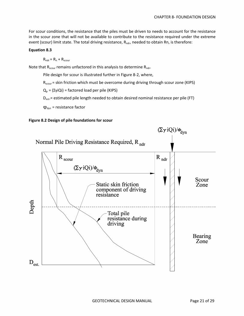
For scour conditions, the resistance that the piles must be driven to needs to account for the resistance in the scour zone that will not be available to contribute to the resistance required under the extreme event (scour) limit state. The total driving resistance, Rndr, needed to obtain Rn, is therefore:
Equation 8.3
Rndr = Rn + Rscour
Note that Rscour remains unfactored in this analysis to determine Rndr.
Pile design for scour is illustrated further in Figure 8-2, where,
Rscour = skin friction which must be overcome during driving through scour zone (KIPS)
Qp = (ΣγiQi) = factored load per pile (KIPS)
Dest.= estimated pile length needed to obtain desired nominal resistance per pile (FT)
ϕdyn = resistance factor
Figure 8.2 Design of pile foundations for scour

CHAPTER 8- FOUNDATION DESIGN
GEOTECHNICAL DESIGN MANUAL Page 22 of 29
8.12.5.1.1 SEISMIC DESIGN FOR PILE FOUNDATIONS For seismic design, all soil within and above liquefiable zones, shall not be considered to contribute axial compressive resistance. Downdrag resulting from liquefaction induced settlement shall be determined as specified in AASHTO (2014) and included in the loads applied to the foundation. Static downdrag loads should not be combined with seismic downdrag loads due to liquefaction.
The available factored geotechnical resistance should be greater than the factored loads applied to the pile, including the downdrag, at the extreme event limit state. The pile foundation shall be designed to structurally resist the downdrag plus structure loads. Pile design for liquefaction downdrag is illustrated in Figure 8.3, where,
RSdd = skin friction which must be overcome during driving through downdrag zone
Qp = (ΣγiQi) = factored load per pile, excluding downdrag load
DD = downdrag load per pile
Dest. = estimated pile length needed to obtain desired nominal resistance per pile
ϕseis = resistance factor for seismic conditions
γp = load factor for downdrag
The nominal bearing resistance of the pile needed to resist the factored loads, including downdrag, is therefore,
Equation 8.4
Rn = (ΣγiQi)/ϕseis + γpDD/ϕseis
The total driving resistance, Rndr, needed to obtain Rn, must account for the skin friction that has to be overcome during pile driving that does not contribute to the design resistance of the pile. Therefore:
Equation 8.5
Rndr = Rn + RSdd
Note that RSdd remains unfactored in this analysis to determine Rndr.

CHAPTER 8- FOUNDATION DESIGN
GEOTECHNICAL DESIGN MANUAL Page 23 of 29
Figure 8.3 Design of pile foundations for liquefaction downdrag (WSDOT, 2006)
The static analysis procedures in the AASHTO (2014) should be used to estimate the skin friction within, above and below, the downdrag zone and to estimate pile lengths required to achieve the required bearing resistance. For this calculation, it should be assumed that the soil subject to downdrag still contributes overburden stress to the soil below the downdrag zone.
The pile foundation shall also be designed to resist the horizontal force resulting from lateral spreading, if applicable, or the liquefiable soil shall be improved to prevent liquefaction and lateral spreading. For lateral soil resistance of the pile foundation, the P-y curve soil parameters should be reduced to account for liquefaction. To determine the amount of reduction, the duration of strong shaking and the ability of the soil to fully develop a liquefied condition during the period of strong shaking should be considered.
The force resulting from flow failure/lateral spreading should be calculated as described in Chapter 6. In general, the lateral spreading force should not be combined with the seismic forces. See Chapter 6, “Seismic Design” for additional guidance regarding this issue.
8.13 DRILLED SHAFT FOUNDATION DESIGN
Refer to AASHTO (2014), Article 10.8 for drilled shaft design requirements. Also reference the FHWA design manual “Drilled Shafts: Construction Procedures and LRFD Design Methods” (Brown, et al., 2010) for additional design guidance. Drilled shaft design should meet or exceed the requirements specified for each limit state. ODOT standards and policies regarding drilled shaft design and construction shall also be followed.

CHAPTER 8- FOUNDATION DESIGN
GEOTECHNICAL DESIGN MANUAL Page 24 of 29
Common shaft sizes range from 3 feet to 8 feet in diameter in 6 inch increments. Larger shaft diameters are also possible. The minimum shaft diameter is 12 inches.
Once the shaft locations and foundation materials and properties are known, the drilled shaft design process for normal bridge projects typically consists of the following:
• Determine scour depths (if applicable), • Determine liquefaction potential and depths; estimate seismic induced settlement (if
applicable), • Evaluate long-term embankment settlement and downdrag potential, • Select most appropriate shaft diameter(s) in consultation with structure designer, • Determine (in consult with the structure designer) whether or not permanent casing will be
used, • Calculate nominal single shaft resistance as a function of depth, • Select and apply resistance factors to nominal resistance, • Estimate downdrag loads (if applicable), • Estimate shaft or shaft group settlement and adjust shaft diameter or lengths if necessary to
limit settlement to service state limits, • Determine p-y curve parameters for lateral load analysis; modify parameters for liquefied soils
(if applicable),
The diameter of shafts will usually be controlled by the superstructure design loads and the configuration of the structure but consideration should also be given to the foundation materials to be excavated. If boulders or large cobbles are anticipated, attempt to size the shafts large enough so the boulders or cobbles can be more easily removed if possible. Shaft diameters may also need to be increased to withstand seismic loading conditions. The geotechnical engineer and the bridge designer should confer and decide early on in the design process the most appropriate shaft diameter(s) to use for the bridge, given the loading conditions, subsurface conditions at the site and other factors. Also decide early on with the bridge designer if permanent casing is desired since this will affect both structural and geotechnical designs. Specify each shaft as either a “friction” or “end bearing” shaft since this dictates the final cleanout requirements in the specifications.
When the drilled shaft design calls for a specified length of shaft embedment into a bearing layer (rock socket) and the top of the bearing layer is not well defined, consideration should be given to adding an additional length of shaft reinforcement to the length required to reach the estimated tip elevation. This extra length is to account for the uncertainty and variability in the final shaft length. This practice is much preferred instead of having to splice on additional reinforcement in the field during which time the shaft excavation remains open. Any extra reinforcement length that is not needed can be easily cut off prior to steel placement once the final shaft tip elevation is known. CSL tubes would also need to be either cut off and recapped or otherwise adjusted. This additional reinforcement length should be determined by the geotechnical engineer based on an evaluation of the site geology, location of borehole information and the potential variability of the bearing layer surface at the plan location off the shaft. The additional recommended length should be provided in the Geotechnical Report and included in the project Special Provisions. Refer to the Standard Special Provisions for Section 00512 for further guidance and details of this application.
If a minimum rock embedment (socket) depth is required, specify the reason for the rock embedment. Try to minimize hard rock embedment depths if possible since this adds substantially to the cost of drilled shafts.

CHAPTER 8- FOUNDATION DESIGN
GEOTECHNICAL DESIGN MANUAL Page 25 of 29
Settlement may control the design of drilled shafts in cases where side resistance (friction) is minimal, loads are high and the shafts are primarily end bearing on compressible soil. The shaft settlement necessary to mobilize end bearing resistance may exceed that allowed by the bridge designer. Confer with the bridge designer to determine shaft service loads and allowable amounts of shaft settlement. Refer to the AASHTO (2014) methods to calculate the settlement of individual shafts or shaft groups. Compare this settlement to the maximum allowable settlement and modify the shaft design if necessary to reduce the estimated settlement to acceptable levels.
8.13.1 DRILLED SHAFT BASE GROUTING Drilled shaft base grouting (or post-grouting) is a process that generally involves pumping cement grout under pressure beneath the base of the shaft to increase the tip resistance. This technique is mostly effectively used for sandy soils with very little fines content. The grout is pumped through pipes into a grout-distribution system attached to the base of the drilled shaft reinforcement. After the shaft is constructed and the concrete has gained adequate strength, grout is pumped through the grout system until grout is returned to the surface. The return valves are then closed and pressure is applied to the system to force grout out of tubes at the base of the shaft into the soil or to inflate a rubber membrane. Grout is pumped under pressure until a specified pressure criteria is achieved.
Shaft base grouting is a relatively new shaft construction technique in the U.S. and currently not addressed in AASHTO (2014). As such, the use of shaft post grouting on ODOT projects must be approved by the HQ Bridge Engineering Section prior to use.
8.13.2 NEARBY STRUCTURES Where shaft foundations are placed adjacent to existing structures, the influence of the existing structure(s) on the behavior of the foundation, and the effect of the foundation on the existing structures, including vibration effects due to casing installation, should be investigated. In addition, the impact of caving soils during shaft excavation on the stability of foundations supporting adjacent structures should be evaluated. At locations where existing structure foundations are adjacent to the proposed shaft foundation, or where a shaft excavation cave-in could adversely affect an existing foundation, the design should require that casing be advanced as the shaft excavation proceeds.
8.13.3 SCOUR The effect of scour shall be considered in the determination of the shaft penetration. The shaft foundation shall be designed so that the shaft penetration and resistance remaining after the design scour events satisfies the required nominal axial and lateral resistance. For this calculation, it shall be
assumed that the soil lost due to scour does not contribute to the overburden stress in the soil below the scour zone. The shaft foundation shall be designed to resist debris loads occurring during the flood event in addition to the loads applied from the structure.
Resistance factors for use with scour at the strength limit state are the same as those used without scour. The axial resistance of the material lost due to scour shall not be included in the shaft resistance.
8.13.4 EXTREME EVENT LIMIT STATE DESIGN OF DRILLED SHAFTS For downdrag due to liquefaction, the nominal shaft resistance available to support structure loads plus downdrag shall be estimated by considering only the positive skin and tip resistance below the lowest layer contributing to the downdrag. For this calculation, it shall be assumed that the soil contributing to downdrag does contribute to the overburden stress in the soil below the downdrag zone. The available factored geotechnical resistance should be greater than the factored loads applied to the shaft,

CHAPTER 8- FOUNDATION DESIGN
GEOTECHNICAL DESIGN MANUAL Page 26 of 29
including the downdrag loads, at the strength limit state. The shaft foundation shall be designed to structurally resist the downdrag plus structure loads.
8.14 MICROPILES
Micropiles shall be designed in accordance with Article 10.9 of the AASHTO (2014). Additional information on micropile design may be found in the FHWA Reference Manual; Micropile Design and Construction, Publication No. FHWA NHI-05-039 (Sabatini, et. al., 2005).
CHAPTER 8- FOUNDATION DESIGN
GEOTECHNICAL DESIGN MANUAL Page 27 of 29
8.15 REFERENCES
• AASHTO, 1988, “Manual on Subsurface Investigations”. • AASHTO, 2010, “Standard of Practice for Assessment of Corrosion of Steel Piling for Non-Marine
Applications”, AASHTO Report R 27-01 (2010), American Association of State Highway and Transportation Officials, Washington, D.C.
• AASHTO, 2011. “AASHTO Guide Specifications for LRFD Seismic Bridge Design”, 2nd Edition and Interim Revisions, American Association of State Highway and Transportation Officials, Washington, D.C. (Note: most current edition shall be used)
• AASHTO, 2014, “LRFD Bridge Design Specifications”, American Association of State Highway and Transportation Officials, Seventh Edition, Washington, D.C. (Note: most current edition shall be used).
• Adama Engineering, Inc., 2003, “Foundation Stress and Settlement Analysis Program (FoSSA)”, Newark, N.J., www.GeoPrograms.com
• Arneson, L.A., Zevenbergen, L. W., Lagasse, P.F., Clopper, P.E., 2012. “Evaluating Scour at Bridges”, FHWA-HIF-12-003 HEC-18, 5th Edition, Federal Highway Administration, Washington, D.C.
• Beavers, J.A. and Durr, C.L., 1998, “Corrosion of Steel Piling in Non-Marine Applications”, NCHRP Project 10-46, Report 408, National Cooperative Highway Research Program, Transportation Research Board, Washington, D.C
• Bowles, J., 1988. https://infohost.nmt.edu/~Mehrdad/foundation/hdout/SpecialFootings.pdf, 4th Edition, McGraw-Hill Book Company.
• Briaud, J., and Tucker, L., 1997. “Design and Construction Guidelines for Downdrag on Uncoated and Bitumen-Coated Piles”, NCHRP Report 393, Transportation Research Board, National Research Council, Washington, D.C.
• Briaud, J., 1989. “The Pressuremeter Test for Highway Applications”, FHWA-IP-89-008, Federal Highway Administration, Washington, D.C.
• Briaud, J. and Miran, J., 1992. “The Cone Penetrometer Test”, FHWA-SA-91-043, Federal Highway Administration, Washington, D.C.
• Brown, D.A., Turner, J.P., Castelli, R. J., 2010. “Geotechnical Engineering Circular No. 10, Drilled Shafts: Construction Procedures and LRFD Design Methods”, Report No.FHWA-NHI-10-016, Federal Highway Administration, Washington, D.C.
• Elias, V., Christopher, B.R., and Berg, R.R., 2001, “Mechanically Stabilized Earth Walls and Reinforced Soil Slopes, Design and Construction Guidelines”, Federal Highway Administration, FHWA-NHI-00-043.
• Gifford, D. G., J. R. Kraemer, J. R. Wheeler, and A. F. McKown. 1987. “Spread Footings for Highway Bridges.” FHWA/RD-86/185. Federal Highway Administration, U.S. Department of Transportation, Washington, DC, p. 229.
• Hannigan, P.J., G.G. Goble, G.E. Likins and F. Rausche, 2006. “Design and Construction of Driven Pile Foundations, Vol 1 & Vol 2”,. FHWA-NHI-05-042 and FHWA-NHI-05-043, Federal Highway Administration, Washington, D.C.
• Kavazanjian, E., Jr., Wang, J-N., Martin, G.R., Shamsabadi, A., Lam, I.P., Dickenson, S.E., and Hung, C.J., 2011. “Geotechnical Engineering Circular No. 3, LRFD Seismic Analysis and Design of Transportation Geotechnical Features and Structural Foundations”, Report No. FHWA-NHI-11-032, Federal Highway Administration, Washington, D.C.
• Kimmerling, R. E. 2002. “https://www.fhwa.dot.gov/engineering/geotech/pubs/010943.pdf”, Report No. FHWA-SA-02-054, Federal Highway Administration, Washington, D.C.
• Moulton, L. K., H. V. S. GangaRao, and G. T. Halverson. 1985. “Tolerable Movement Criteria for Highway Bridges”, FHWA/RD-85/107. Federal Highway Administration, U.S. Department of Transportation, Washington, DC, p. 118.
CHAPTER 8- FOUNDATION DESIGN
GEOTECHNICAL DESIGN MANUAL Page 28 of 29
• Oregon Department of Transportation, Bridge Design Manual, Bridge Engineering Section, most current version.
• Oregon Department of Transportation, Hydraulics Manual, Geo-Environmental Section, 2014. • Oregon Department of Transportation, Soil and Rock Classification Manual, Geo-Environmental
Section, 1987. • Oregon Department of Transportation, "Standard Specifications for Highway Construction", 2015
Edition and related Standard Special Provisions. • Reese, L. C. 1984. “Handbook on Design of Piles and Drilled Shafts Under Lateral Load”. FHWA-IP-
84/11, Federal Highway Administration, U.S. Department of Transportation, Washington, DC. • Reese, L. C., 1986. “Behavior of Piles and Pile Groups Under Lateral Load”,Report No. FHWA/RD-
85/106, U. S. Department of Transportation, Federal Highway Administration, Office of Engineering and Highway Operations Research and Development, Washington D. C., 311
• Sabatini, P.J., Bachus, R.C., Mayne, P.W., Schneider, J.A., and Zettler, T.E., 2002, Geotechnical Engineering Circular No. 5, Geotechnical Engineering Circular No. 5, Evaluation of Soil and Rock Properties, U.S. Department of Transportation, Federal Highway Administration, Washington, D.C.
• Sabatini, P.J., Tanyu, B., Armour, T., Groneck, P., Keeley, J., 2005. “Micropile Design and Construction” (Reference Manual for NHI Course 132078), Federal Highway Administration Report No. FHWA NHI-05-039, Washington, D.C.
• Samtani, N.C., Nowatzki, E.A., Mertz, D.R., 2010. “Selection of Spread Footings on Soil to Support Highway Bridge Structures”, Federal Highway Administration Report No. FHWA-RC/TD-10-001, Washington, D.C.
• Samtani, N. C. and Nowatzki, E., 2006. “Soils and Foundations Reference Manual, Volumes I and II”, FHWA-NHI-06-088 and FHWA-NHI-06-089, Federal Highway Administration, Washington, D.C.
• Washington State Department of Transportation, 2013, https://www.wsdot.wa.gov/Publications/Manuals/M46-03.htm.
APPENDIX
APPENDIX LIST OF TABLES
Table 8.1 Summary of Information Needs and Testing Considerations ................................................. 5 Table 8.2 Strength Limit State Downdrag Load Factors (ref: WSDOT GDM, 2013) ................................ 13
LIST OF FIGURES
Figure 8.1 Example where footing contributes to instability of slope (left figure) vs. example where footing contributes to stability of slope (right figure) ........................................................... 10
Figure 8.2 Design of pile foundations for scour ............................................................................... 21 Figure 8.3 Design of pile foundations for liquefaction downdrag (WSDOT, 2006) ................................ 23
LIST OF EQUATIONS
Equation 8.1 ............................................................................................................................... 12 Equation 8.2 ............................................................................................................................... 20 Equation 8.3 ............................................................................................................................... 21 Equation 8.4 ............................................................................................................................... 22 Equation 8.5 ............................................................................................................................... 22