gyrotracer - wireline mode - eds.com.pk · 3 wireline mode operating manual this manual includes...
TRANSCRIPT

Version 1.1.2.1
GyroTracer™ North‐Seeking Gyroscope
(Wire‐line mode)
Operating Manual
2
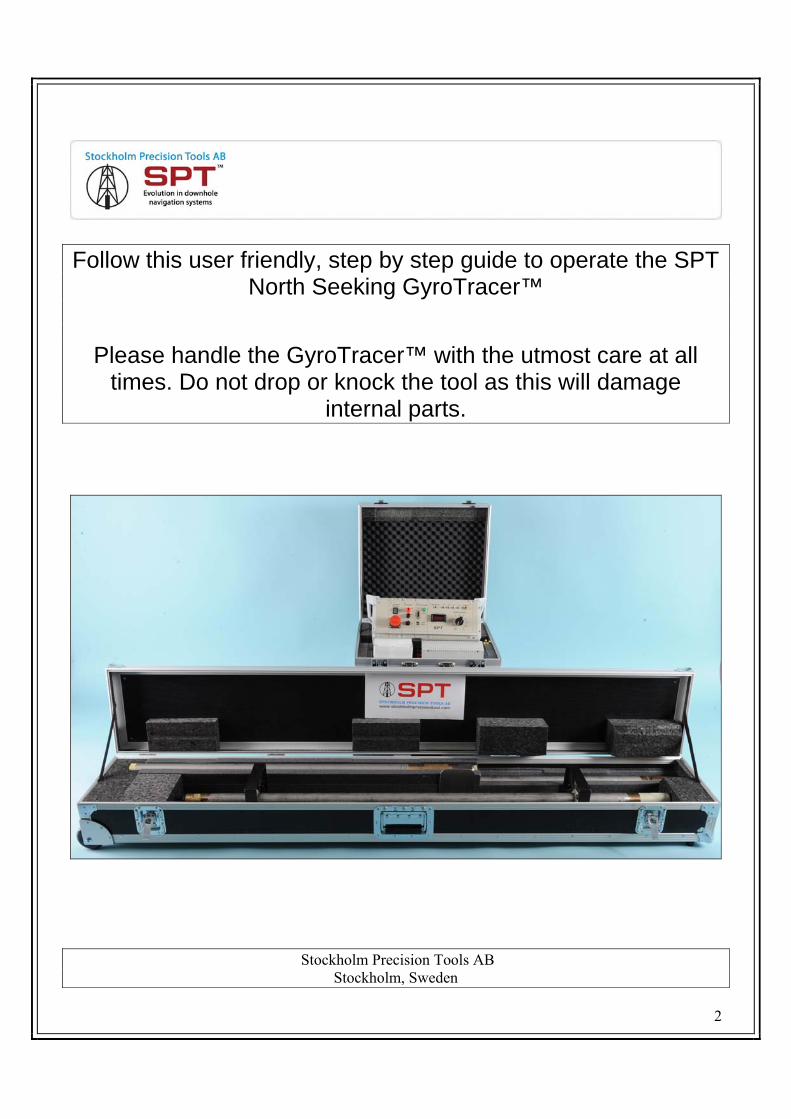
Follow this user friendly, step by step guide to operate the SPT North Seeking GyroTracer™
Please handle the GyroTracer™ with the utmost care at all times. Do not drop or knock the tool as this will damage
internal parts.
Stockholm Precision Tools AB Stockholm, Sweden

3
Wireline Mode Operating Manual
This manual includes step-by-step operating instructions for a typical gyro survey in Wireline Mode. It is strongly recommended that technicians familiarize themselves with proper handling and operation of the Gyro prior to using the system. Installing the software, USB drivers and surface equipment
1. Open your SPT Software (Figure 1 and Figure 2)
Figure 1 Figure 2 2. Leave the SPT Software open for now on your PC 3. Connect the USB cable from the Surface Unit to the PC 4. USB connection for the USB driver must be installed.
Turn on the surface unit with the Current Setting dial to the first position (1). A window Found New Hardware appears on PC. Tick Decline the offer to find driver in Internet, then click Next. Choose installation from the list, or specific place, and then browse to the folder USB-driver of your SPT software. You will see USB High Speed Serial Converter hardware installed. Wait a few moments and once again a window Found New Hardware appears on PC. Repeat same operations for installation of USB Serial Port. Software will simulate functions of COM ports via USB connection. This operation should be made only once on PC. Do not connect the Gyro during this procedure. Find USB - COM port. Open Control Panel, then System, go to the Hardware window, click Device Manager and open ports. For example, we have USB Serial Port, connected to COM3 (Figure 3). This can only be seen with the surface unit switched on. Please note: The SPT software emulates COM-ports with the numbers from 1-6. But computer may have more than 6 COM-ports already assigned. For example, “USB-serial port” may be attached to COM13 but software does not have an opportunity to select COM13. In order to avoid this, rename COM13 to COM3 (from COM1 to COM6). Right-click on “USB Serial port”, select “Properties”.

4
New window appears. Choose window “port options”, click “advanced” and rename COM-port to COM3.
Figure 3 5. Turn off the Surface Unit. 6. For field use, connect the cable from the Decoder of the Surface Unit, Cable Core and Cable
Armor (black to black, red to red) direct to the winch system. For simulation mode, connect from the Surface Unit to the Cable Simulator, Core and Armor IN (Diagram 1).
Please note: The cable simulator is used to introduce resistance into the power/data stream between the surface unit and the telemetry when running the gyro in the laboratory and when it is not connected to the winch. Each setting on the cable simulator dial indicates a different resistance setting with number 1 being the lowest resistance through to number 3 being the highest resistance. The higher the setting on the cable simulator then the higher the setting will be required for the current setting dial on the surface unit.
7. From Core and Armor OUT in the Cable Simulator, connect the test cable to the end of the
Telemetry where the cable head would usually fit. The red banana pin fits the female connection in telemetry and the clip clamps to the telemetry housing.

5
Diagram 1 8. Connect USB or COM cable to the surface unit, then to the computer (Diagram 1). 9. Open the SPT software and open the icon named spt_tools. A new window will appear (Figure 4).
Select Gyro (wire-line mode)/USB. Click just once here (Figure 5).

6
Setting up the survey
Figure 4
Figure 5

7
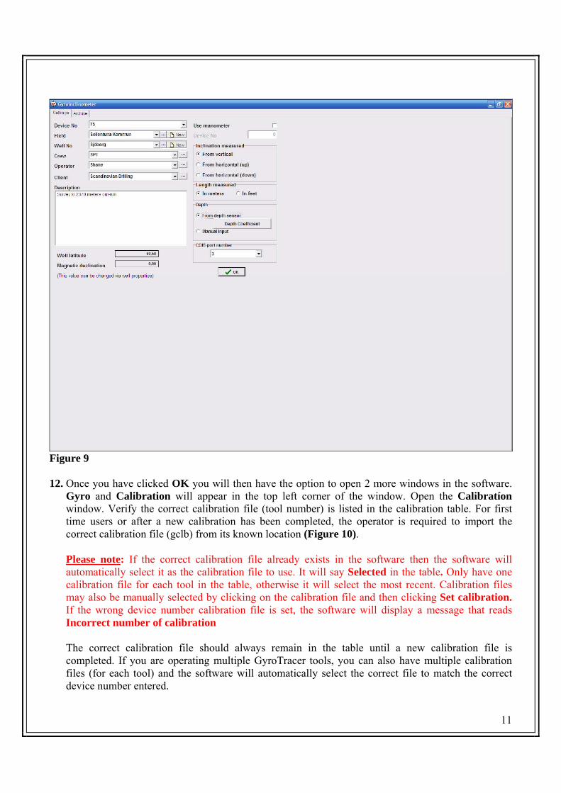
10. The Settings window will appear (Figure 6). Complete the following fields as outlined in steps 11 a) through to n) below and click OK. The Settings screen then should look like as in Figure 6
Figure 6 11. a. Device No - Provides the option to select the correct Gyro Calibration File (tool number).
Verify that the correct gyro number is listed in the Device No field. If the instrument number is incorrect, it can be changed by clicking on the drop-down menu ▼ and selecting the correct option or just enter a new tool number in the entry box Please note: Each gyro has a unit number stamped on the brass rings of the outer barrel and each gyro has a specific calibration file. Using the wrong calibration file will produce inaccurate survey data.
b. Field - Provides the option to organize survey data by field (Figure 7). Enter in the correct Field name. You have the option to use an existing Field name with the drop down arrow (▼), view, edit or delete previous field data with the (···) icon or create a new Field with the New icon. If the operator knows the Local grid offset, Altitude or Field coordinates then enter in this data. Once a new field is created it can be used for all surveys that are done on that property as other parameters will differentiate between surveys.

8
Figure 7
• Field coordinates are used for the specific area of the well or wells • Altitude: is used for the specific area of the well or wells’. Having the Altitude entered gives
calculation from the sea level for that specific location and is put in for mapping of the wells. • Local grid Offset is the degree that is set and normally used by the specific mine site.
Please note: Data entered when creating a new Field will be used for information purposes only and will not influence survey data.
c. Well No. - Provides the option to organize survey data by well name (Figure 8). This option is used for organizing multiple wells in specific fields (properties or mines). Here you have the option to use an existing well name using the drop down arrow (▼), view, edit or delete previous well data with the (···) icon or create a new well with the New icon. Once a new well is created it should only be used for future surveys on that specific well as the latitude field will be incorrect for other wells.
• Enter the new Well location (Figure 8) • Find the Latitude of the well you are going to survey and enter. This should be known by the
operator or use a GPS

9
• Magnetic declination will calculate the magnetic Azimuth difference from the Geographical Azimuth.
• Starting point coordinates is used for the specific well location. • Altitude is used for the specific well location and gives elevation above sea level and is included
for mapping of the wells. • Enter in the correct Well depth of each well in the box.
Figure 8
Please note: You must input the correct latitude for each well as this is required for the gyro to produce accurate data. Additional data (other than latitude) entered when creating a new well name will be used for information purposes only and will not influence survey data.
d. Crew - Provides the option to organize survey data by crew. Here you have the option to use an existing crew name using the drop down arrow (▼), enter in a new crew name in the box or delete previous data with the (···) icon.
e. Operator - Provides the option to organize survey data by operator.
Here you have the option to use an existing crew name using the drop down arrow (▼), enter in a new crew name in the box or delete previous data with the (···) icon.
10
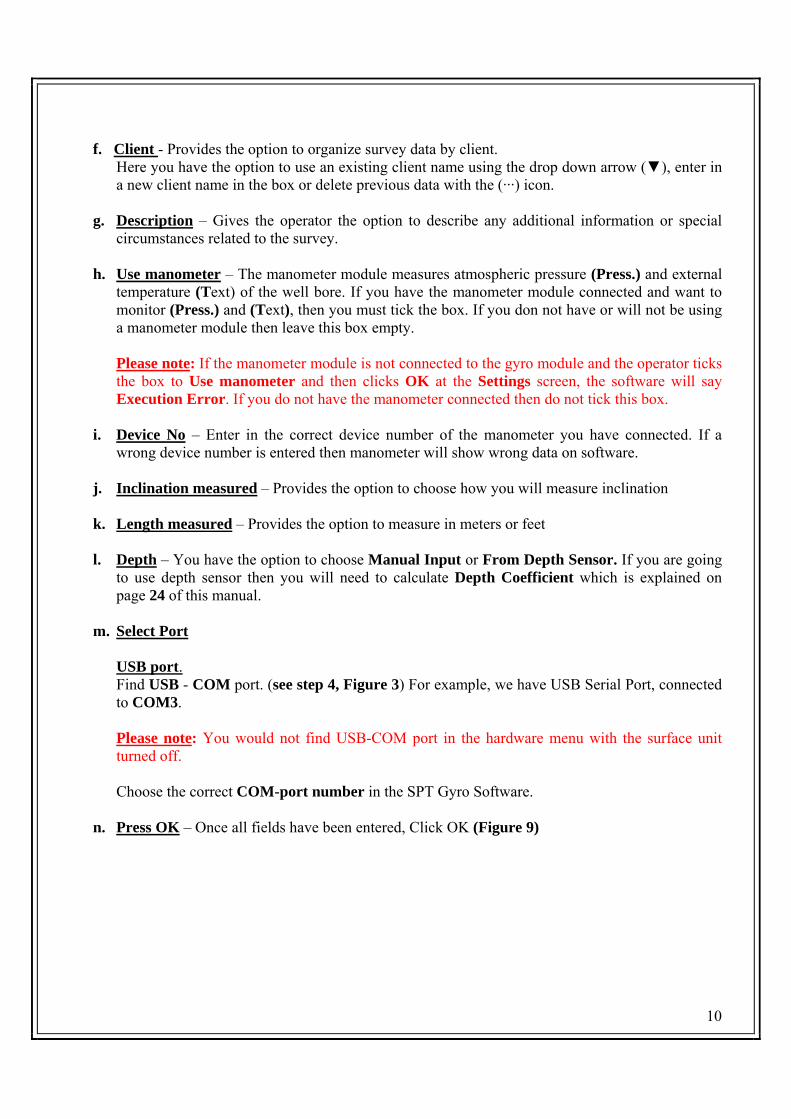
f. Client - Provides the option to organize survey data by client. Here you have the option to use an existing client name using the drop down arrow (▼), enter in a new client name in the box or delete previous data with the (···) icon.
g. Description – Gives the operator the option to describe any additional information or special
circumstances related to the survey.
h. Use manometer – The manometer module measures atmospheric pressure (Press.) and external temperature (Text) of the well bore. If you have the manometer module connected and want to monitor (Press.) and (Text), then you must tick the box. If you don not have or will not be using a manometer module then leave this box empty.
Please note: If the manometer module is not connected to the gyro module and the operator ticks the box to Use manometer and then clicks OK at the Settings screen, the software will say Execution Error. If you do not have the manometer connected then do not tick this box.
i. Device No – Enter in the correct device number of the manometer you have connected. If a wrong device number is entered then manometer will show wrong data on software.
j. Inclination measured – Provides the option to choose how you will measure inclination
k. Length measured – Provides the option to measure in meters or feet
l. Depth – You have the option to choose Manual Input or From Depth Sensor. If you are going
to use depth sensor then you will need to calculate Depth Coefficient which is explained on page 24 of this manual.
m. Select Port
USB port. Find USB - COM port. (see step 4, Figure 3) For example, we have USB Serial Port, connected to COM3.
Please note: You would not find USB-COM port in the hardware menu with the surface unit turned off.
Choose the correct COM-port number in the SPT Gyro Software.
n. Press OK – Once all fields have been entered, Click OK (Figure 9)
11
Figure 9 12. Once you have clicked OK you will then have the option to open 2 more windows in the software.
Gyro and Calibration will appear in the top left corner of the window. Open the Calibratíon window. Verify the correct calibration file (tool number) is listed in the calibration table. For first time users or after a new calibration has been completed, the operator is required to import the correct calibration file (gclb) from its known location (Figure 10).
Please note: If the correct calibration file already exists in the software then the software will automatically select it as the calibration file to use. It will say Selected in the table. Only have one calibration file for each tool in the table, otherwise it will select the most recent. Calibration files may also be manually selected by clicking on the calibration file and then clicking Set calibration. If the wrong device number calibration file is set, the software will display a message that reads Incorrect number of calibration
The correct calibration file should always remain in the table until a new calibration file is completed. If you are operating multiple GyroTracer tools, you can also have multiple calibration files (for each tool) and the software will automatically select the correct file to match the correct device number entered.

12
Figure 10 13. The next step is to open the Gyro window (Figure 11)
Figure 11

13
Switching on equipment The Gyro screen (Figure 11) of the software is where the Gyro is turned on or off, where you can see all information about the Gyro such as temperature, inclination, voltage, accelerometers and depth. Here at this screen is also where you run a survey. You also have the option to run a survey of the toolface. Before a survey can be performed, the Gyro must be switched on. This is shown in steps 14 a. to h.
14 a. Turn ON the Surface Unit by switching the Current Setting dial from the Off position, to
position number 6 or 7. Turn the switch to the correct setting reasonably fast, within 3 seconds This is the optimal position in laboratory mode but it will vary in the field (Diagram 2)
b. Immediately monitor the Current Load on the Surface Unit. Wait for this reading to increase and then stabilize and then click Start on the Gyro screen. It will take about 4 seconds to stabilize and will then make small fluctuations. Once you have clicked Start you will be prompted Command Executed. Click Ok. This activates the Telemetry and begins warning up the tool (Figure 12). The optimal Current Load range is from 200 – 300 in laboratory mode but it will vary in the field.
Diagram 2

14
During simulation mode, the Current Load setting will read approximately .250 milliampere during warm-up time, .300 milliampere when the gyro is switched on and .200 milliampere once the gyro has reached maximum temperature.
Figure 12 Please note: When using the equipment for the first time the starting procedure for steps a. and
b. must be performed differently. Turn on the Surface Unit to position number 7. Do not click Start on the software until you have Requested Telesystem Info to check that the Utele voltage is ok. This is to find the optimal Current Setting position in lab or field mode. If the Utele is incorrect then adjust the dial accordingly. Once you have the correct setting you my click Start and proceed. This Current Setting position should now be the optimal when turning on Surface Unit. It will vary from field to lab mode. Please follow from step b. after clicking start.
c. Next step is to immediately click Request Telesystem Info. This is very important as this shows how much voltage is going to the Gyro (Utele). The temperature of the Telemetry is also shown here (Ttele). When you request, it will take a few seconds to update. The correct voltage is approximately between 85 – 100 Utele and will be shown in black digits when in the correct range. The optimal Utele range is 90 – 95 volts. If it is outside the correct voltage range, the digits will be shown in red and you will be prompted Wrong Voltage. If this is the case you
15
must quickly adjust the Current Setting dial on the Surface Unit. If the reading is showing below 85 volts or in the red, then switch up 1 position. If the reading is showing above 100 volts or in the red, then switch down 1 position. Immediately click Request Telesystem Info again after doing this to check again. If the voltage is still showing in the red, then adjust the Current Setting dial again quickly and accordingly. Please note: It is very important to adjust the Current Setting dial quickly if the voltage is showing below the optimal range. Try to not leave it any longer than 3 seconds. If it stays at a low voltage for a short period of time, electrical components in the telemetry module may burn. The Gyro is not at as much risk if the voltage is showing above the optimal reading but it is still important to adjust the Current Setting down a position quickly so it is in the correct range
d. Tick the Auto request box and then click on Request Inclinometer. This will automatically
refresh all information every few seconds for Inclinometer and Telesystem. The Inclinometer has 4 boxes showing live data of the Inclination angle (Inclin), Toolface angle (Roll), temperature of the Inclinometer (Tinc), and temperature of the Gyro (Tgyro). You will know when Auto Request is activated when the colour of the text in Request Inclinometer and other boxes changes from black to grey and they cannot be activated.
e. Each Gyro has an operating temperature of approximately 60° - 63° Celsius. This can be
monitored in Tgyro. Once the Gyro has been started, it will begin to warm up. You will see the digits in red and continually increasing. Once it has reached approximately 60° Celsius, the digits will change to black and stabilize and it will have reached maximum temperature.
f. The Gyro is now ready to be turned on. The Gyro can actually be turned on when the
temperature has reached 45° Celsius or in colder environments, 35° Celsius. First uncheck Auto request box so you can activate other options. Once the Gyro is turned on, it will speed up the warming process.
g. Click Gyro On (Figure 13). You will be prompted with the message Command Executed. Click
OK. Next immediately click Request Telesystem Info to check voltage again. When the Gyro is turned on it draws more current and therefore it is common for the Utele voltage to decrease. Monitor this as it may drop below 85 volts and go into the red. If so, adjust quickly and accordingly up 1 position.
Please note: It is important to monitor regularly the Utele voltage on the software and the Current Load on the Surface Unit right up until you begin surveying. This can fluctuate quite regularly until it stabilizes after the Gyro has been turned on and reached operating temperature. You will also notice that the Utele will also slightly increase once the Gyro has reached operating temperature. It is also important to Request Telesystem Info every so often during surveys to check all is working ok.
h. Once the temperature (Tgyro) has reached maximum operating temperature, changed to black and stabilized, wait a minimum of 10 minutes before taking the first survey. This time will need to be increased for colder environments as instructed by SPT during training.
Please note: When using the cable simulator for simulation mode, never change the resistance switch on the cable simulator whilst the Gyro is on.

16
Figure 13
Gyro at maximum temperature

17
15. Surveying can now begin. If you have chosen Manual Input at the Settings window, you can take independent surveys at certain stations. You also have the option to choose how many surveys you would like to take at each station by changing the digits using the ↑↓ arrows. You will find this just below Show/Hide Sensors. You can change this in between surveys once it has finished. If you set this to 3 for example, 3 consecutive independent surveys at that station will be recorded.
Surveying 16. To begin a survey, click on Run survey. Each survey will take approximately one minute. During
the whole period of each survey a message will be shown on the screen. Attention! Measuring! Don’t move device (Figure 14)
17. After each survey is complete, the results will instantly tally in the Survey results table on the screen (Figure 15). These results can also be viewed in Archives for more in depth data. Now move to next position and take a survey.
Figure 14

18
Figure 15 18. When running survey’s with Manual Input, you have the option to manually add depths. You can
do this by clicking on Depth. If you would like to use incremental depths then you first choose the option of Run-in or Run-out then set the incremental depth in meters with the ↑↓ arrows or enter it manually. You will first need a starting depth which you can enter in the Depth window. You then click on Increment depth to keep adding an extra 10 meters for example and then click Run survey to take a survey at each manual or incremental depth.
19. If the operator chooses the option to run survey’s using the Depth sensor then this can only be done
if there is an encoder connected from the winch to the Surface Unit by a depth sensor cable. The depth reading will show below Depth on the left side of the screen. The depth reading will move as the winch is run in or out. Simply stop at the desired depth and click Run survey. Depth coefficient needs to be calculated first which is shown on page 30 of this manual.
20. Show/Hide sensors (Figure 15). This option allows the operator to view or hide the Gyro signals
and the X, Y and Z accelerometers.
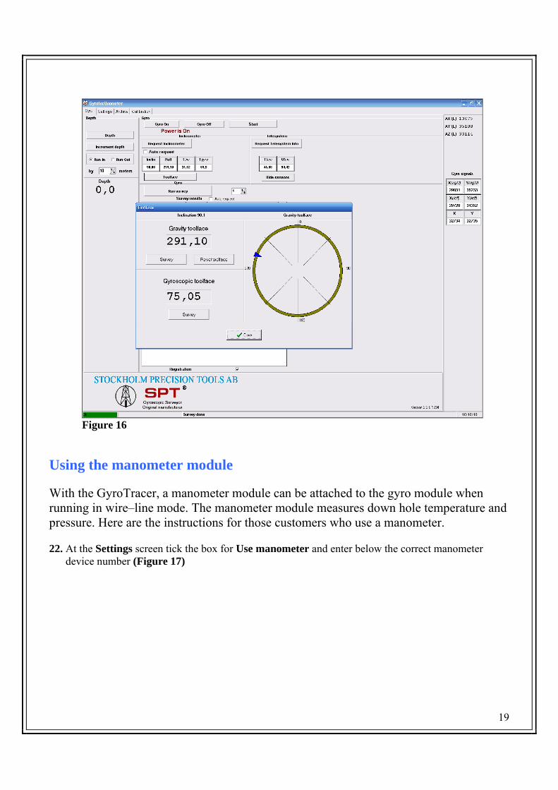
21. The GyroTracer also has the option for Toolface orientation (Figure 16). Toolface orientation can performed for applications like orientation of wedges or the down hole motor. By clicking on Toolface you have the option to work with Gravity toolface (inclined holes), or Gyroscopic toolface (vertical holes). Toolface can also be reset to find high side. This is explained in more depth in the GyroTracer Toolface Orientation Manual.
19
Figure 16
Using the manometer module
With the GyroTracer, a manometer module can be attached to the gyro module when running in wire–line mode. The manometer module measures down hole temperature and pressure. Here are the instructions for those customers who use a manometer.
22. At the Settings screen tick the box for Use manometer and enter below the correct manometer
device number (Figure 17)

20
Figure 17
23. The atmospheric pressure (Press.) and the external temperature (Text) have 2 different modes: Man. mode 1 and Man. mode 2. You can swap between these 2 different modes at any time while the gyro is on and in the well. Click on the mode you want to use. The software will then display a window which says Command Executed. Click OK (Figure 18). That mode has now been set. To update this information you need to tick the Manometer box on the Gyro screen and then click on Request Inclinometer or tick the Auto request box and then click on Request Inclinometer to continuously update every 3 seconds Man. mode 1 is to be used when the gyro is at deep depths (higher sensitivity) Man. mode 2 is to be used when the gyro is at shallow depths (lower sensitivity)

21
Figure 18 The units of pressure shown in software are in bar. To convert to PSI, multiply the pressure value by 14.5 The units of temperature are shown in degrees Celsius When running a survey with a manometer, the SPT software will operate as normal as seen in (Figure 19). The manometer recordings are also saved in Archives under Pressure

22
Figure 19 The wireline mode gyro survey is now complete 24. When all surveying is complete and all data has been recorded in Archives, you may now switch off
the Gyro. 25. Click on Gyro Off on the software screen. Command Executed. Click OK
26. Switch off the Surface Unit immediately after by switching the Current Setting dial direct to the
Off position (Diagram 3)
23
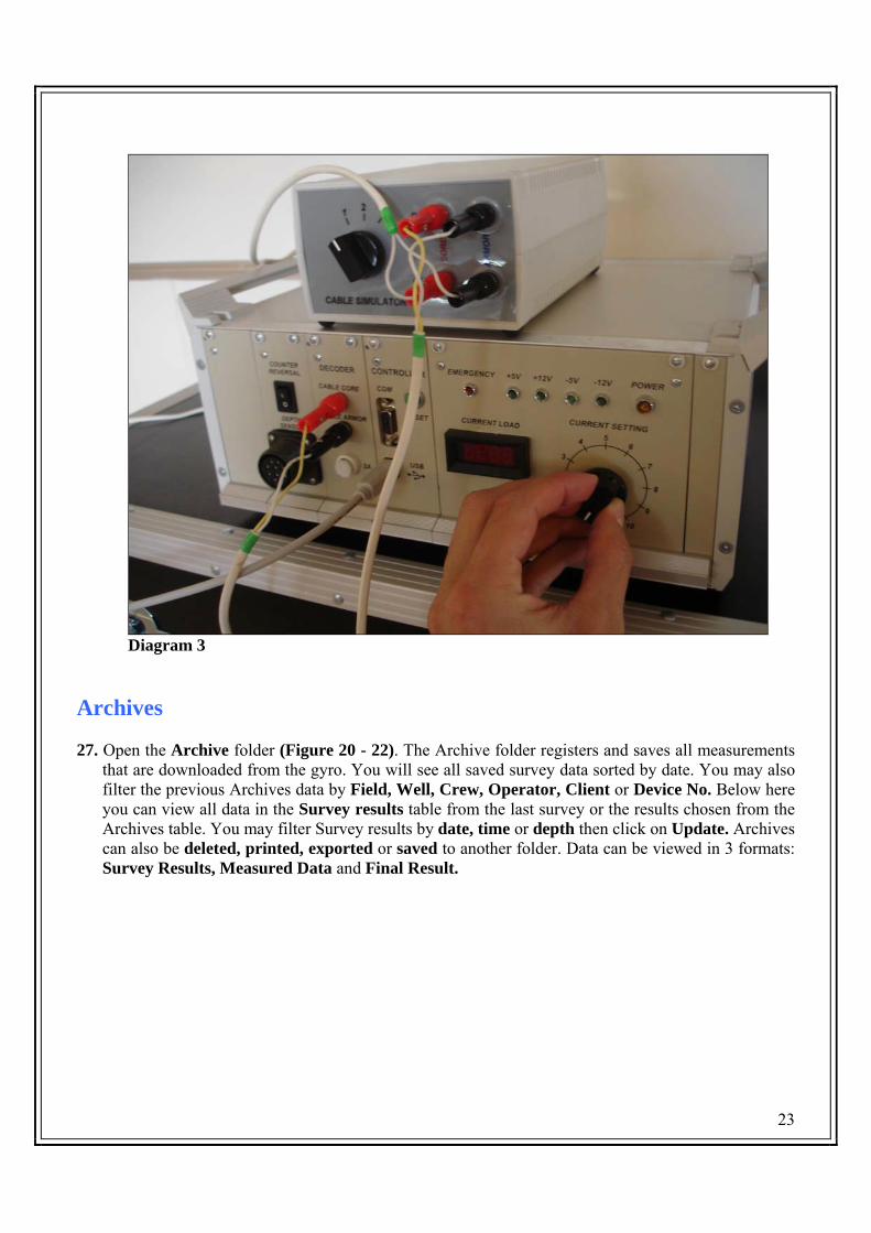
Diagram 3 Archives 27. Open the Archive folder (Figure 20 - 22). The Archive folder registers and saves all measurements
that are downloaded from the gyro. You will see all saved survey data sorted by date. You may also filter the previous Archives data by Field, Well, Crew, Operator, Client or Device No. Below here you can view all data in the Survey results table from the last survey or the results chosen from the Archives table. You may filter Survey results by date, time or depth then click on Update. Archives can also be deleted, printed, exported or saved to another folder. Data can be viewed in 3 formats: Survey Results, Measured Data and Final Result.

24
Figure 20 – Survey Results Scroll through Survey Results, Measured Data and Final Result to view different data results.
25
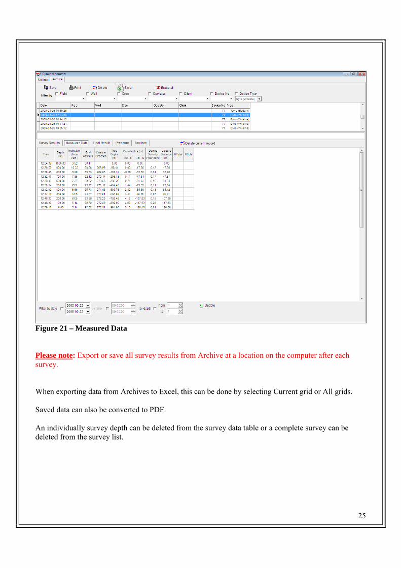
Figure 21 – Measured Data Please note: Export or save all survey results from Archive at a location on the computer after each survey. When exporting data from Archives to Excel, this can be done by selecting Current grid or All grids. Saved data can also be converted to PDF. An individually survey depth can be deleted from the survey data table or a complete survey can be deleted from the survey list.

26
Figure 22 – Final Result Results can be filtered by date, time and depth. Depths may also be interpolated by entering the depth step required and clicking on Update. To revert back to original depths, tick Use original depth and click Update Tuning gyro For those customers who are operating the SPT GyroTracer, and using the tool for the first time or running on a new software or PC for the first time, the survey time of each tool needs to be checked and possibly tuned. This is required to be done only once for each tool. Tuning gyro sets the survey time for each tool. This value needs to be entered in the SPT Calibration software on the Calibration screen. Each customer will receive these values from SPT for each tool they buy. This will also be covered in the training course.

27
It’s important to set up Tuning gyro when installing the equipment for the first time. After installing once, the value will for each tool will be saved and they will not need to be changed again. The only occasion they will be required to be checked is if the survey time happens to change in the future. To set up Gyro tuning, go to the Calibration software (Figure 23)
Figure 23 Go to the Calibration screen. Click on Tuning gyro… tab. A window called Tuning… will open (Figure 24) In this three boxes, enter in the correct values if they are different than what has been supplied by SPT. Click OK to save the values. Close the Calibration software and navigate back to the survey software spt_tools.

28
Whilst opening and closing software programs, and alternating between the two, the surface equipment can remain on if the voltage is correct. Once a software has been closed while the surface equipment is on, open the software once again, click Gyro ON at the Gyro screen. This will activate the software and communication with the gyro will continue.
Figure 24

29
ATTENTION - STANDARD OPERATING PROCEDURES
• Do not move the Gyro when it is recording data. This will produce inaccurate data. • Transport the equipment in the carry cases supplied at all times. Never transport
the gyro module in PVC piping or any other method in the vehicle. • Frequently verify that data is registering in the archive during the survey. • Do not allow the gyro to land on or hit the inner tube or any other obstruction
inside the drill rods as the shock will damage the instrument. • Verify the location of all cross-over subs, float subs, interchange, or any other
potential obstruction that could be impacted by the Gyro during the survey. • When surveying inside drill pipe with internal upset tool-joints - use bow-spring
centralizers with weight bar and exercise caution. • Do not traverse (move gyro between survey stations) in excess of 100 m. per
minute. • The Gyro must be on while seating the mule shoe stinger to the UBHO. • Never connect the surface unit direct to the Gyro with the cable supplied. Always
connect from the cable simulator when in lab mode. • Always use a shock absorber on the bottom • Always use centralizers when surveying vertical holes or close to vertical, large
diameter wells or for orientation work. • The gyro can always be in warm up mode before putting it in the hole or well but
never switch the gyro ON until it is in the hole. • Switch OFF the gyro before POOH • Occasionally check the gyro signals throughout a survey • Monitor the UTele (voltage) and Tgyro (gyro temperature) throughout the survey • Report any mishaps to a member of staff at SPT • It is always extremely important to warm up the gyro very well before the first
survey. Never do the first survey until the temperature has been at maximum for a minimum of 5 minutes. This is more for colder climates as instructed during training.
Please note: The GyroTracer may be moved from one place to another with the surface unit switched on and Gyro turned off. Click Gyro Off, tick Auto Request, then click Request Inclinometer and check the voltage during transportation. This will keep the Gyro warm. Click Gyro On to power up again.

30
Procedure to assemble the gyro tool string
1. Carefully remove the Gyro module from the case and lay on the catwalk, ground or rig floor. 2. Remove the Telemetry module from the case. 3. Remove protective caps from the Gyro and Telemetry. 4. Clean, examine and lubricate (silicon grease) o-rings and threads. 5. Lift the Gyro module from the ground and carefully place the bottom rubber pointing down on
the ground. 6. With the Gyro standing on end, screw on the Telemetry hand tight. 7. Lay the two modules down on V-blocks. 8. If in the mining sector and not operating with running gear: 9. Connect the cable head and carefully tighten all connections of the tool string with the
appropriate tools. 10. If operating with running gear: 11. Remove the bottom rubber nose end and connect the bottom adaptor. 12. Connect centralizers to top (feedthru) and bottom of the tool. 13. Connect bottom shock absorber to bottom centralizer. 14. Connect sinker bars to bottom of tool if running with them. 15. Connect cable head. 16. Once the full tool string is connected on the V-blocks, tighten all connections with the
appropriate tool.
Procedure to disassemble the gyro tool string Repeat the above steps in reverse.
Please note: When assembling or disassembling the gyro tool string, do not use excessive force when tightening and NEVER knock or hammer the gyro module or any parts connected to the gyro module when connecting or disconnecting parts. When tool is laid horizontal, never let the gyro module or any other part of the tool string lift while tightening. If possible, have a second person to hold the other end Otherwise it may fall back onto the stands or floor and may damage the gyro sensor. When assembling or disassembling the tool whilst hanging from the travelling block swivel or a lubricator, always have a person holding the bottom end of the tool to stop any swinging of the instrument and prevent knocking into the well head or any obstruction around the turntable.

31
Calculating Depth Coefficient (DC)
1) Go to Settings screen 2) Tick From Depth Sensor 3) Open Depth Coefficient window 4) Set DC to 1.0 5) Click OK at DC window 6) Click OK at Settings window 7) Go to Gyro screen 8) Open Depth window 9) Set Depth to 0.0m 10) Winch must also be wound back and winch counter set to 0 11) Run out cable 100m taking reading from winch counter 12) Check the Depth sensor reading of the software at the 100m mark of cable 13) Lets say for example the depth on the Gyro window reads 185 14) Now calculate Depth Coefficient 15) 185/100 = 1.85 16) Go to Settings screen 17) Open DC window 18) Enter 1.85 for example 19) Click OK at DC window 20) Click OK at Settings screen 21) Wind back winch to 0 22) Open Gyro window 23) Depth should have returned back to 0 24) Now for a test, run out cable 50m for example. 25) The depth reading on the software should also show 50m 26) Run cable back to 0m. Software should also show 0m 27) If this is correct, you are now ready to start a survey Please remember to add the length of the tool to the length of the cable before dividing this length by the depth sensor length and calculating DC When finding depth coefficient, run out cable 50 - 100 metres. This will give you a more accurate figure than 10 metres. When you first calculate DC, repeat the procedure again straight away just to be sure you get the same figures. Also remember that you need to re-calculate depth coefficient if you change over any of the following: cable, winch, winch counter or encoder. They could have a different diameter to the original which will affect depth coefficient.

32
Surface Unit Buttons and Indicators:
Counter reversal: If counting is reversed (when the tool is lowered into the hole and the software shows you are pulling out), switch the Counter Reversal button to correct the reversal.
Reset Button: In cases of a freeze in the surface unit controller, press the green Reset button at the front to reset the surface unit for 3 seconds.
Circuit Breaker reset: In cases of a short from the power supply to ground or any other short, press the Circuit Breaker Reset button at the back of the Surface Unit for 5 seconds to reset the surface unit.
Emergency Indicator: Light comes on when surface unit is overheating Troubleshooting
1. Operator clicks Start on software but no communication occurs.
This is likely to be due to a fault in the connection or communication somewhere in the circuit.
Check all cables are connected properly. Check that cable head and wire-line are adequately connected. Check that you are using the correct USB COM port number (see Step 4). Check that the Surface Unit is switched on first. The software may be hanging. Close down all software windows and re-open, try again.
2. Operator clicks Gyro on at the software but is not given confirmation with Command
Executed but instead the software shows Error. This is due to a communication problem somewhere in the system. Check that the cable head does
not contain any water. Check you have not opened the software twice. If so, shut down all software and start the procedure again. The resistance in the wire-line may be too high for the Gyro. Check cable and tool for proper connections or faults.
3. The Current Setting is switched to usual position but Utele reading is very low.
This problem is most likely due to having the wrong CLB file in the software or no CLB file. The CLB file is saved in the CALIBR folder in the software. Check the correct CLB tool number is in this folder. Check all cables and running gear is connected correctly. Also check the correct device number has been selected at the ‘Settings’ screen.
The Current Setting switch may be in the wrong position.

33
4. During the warm up or surveying procedure the software randomly shows message Receive Error or Send Error.
If you come across this problem, click Gyro On. This should clear the message and everything
should be working ok again. If this problem continues to happen then it is most likely that the communication is weak between the Surface Unit and Telemetry. This could be caused by a number of factors including: water or moisture could be in the cable head which is disturbing the communication or the resistance of the wire-line maybe too high for the equipment. These 2 factors need to be checked if this problem continues.
5. The SPT software freezes.
If you encounter this problem then it is most likely because too many windows in the software have been opened up, clicking on an icon too many times or just an error in the software. To clear this problem, close all windows in the software and restart the software again.
6. Wrong calibration file.
The results of a survey may show unusual, unexpected data. The first thing to check is that you have imported the correct calibration file. If the calibration file is not on the list, then it needs to be imported from the folder or desktop where it is stored.
7. The current setting on the surface unit shows normal reading but the UTele voltage on the software shows 0.00
The CLB file for the device being used is not in the CALIBR folder of the software. Place the
correct CLB file into the CALIBR of the software then close down all software and start again
8. When the gyro is switched on, the Current Load is giving a low reading.
The most likely cause is a loose connection somewhere in the tool string. Check that the telemetry is connected tightly to the gyro module or if other any other running gear is connected such as centralizers, check these connections also.
9. When the gyro is switched on, the Current Load is showing a reading of approximately .050 The most common cause of this fault is a bad connection between the gyro and telemetry modules. Either the telemetry pin contact or the gyro connection contact could be damaged. Disconnect the two modules and thoroughly inspect the connections for damage and faults. Check the telemetry pin is not loose or dislodged. Check gyro spring mounted connector has not sunken into the chassis. 10. Vibrations, abnormal volume or humming sound or inconsistency of rotation speed of gyro sensor. Any of the above symptoms could be a sign of damage to the gyro sensor due to an impact. Set the
tool up in the workshop at a known reference point. Survey this point for comparison. Monitor gyro behaviour and sound. Check gyro signals at the end of each survey.

34
Report all faults and problems to SPT When a fault or problem occurs with the equipment, carefully follow the trouble shooting answers above. If the problem cannot be rectified, please contact your SPT representative. For more serious faults such as suspected sensor damage or no power supply to the tool, contact your SPT representative as soon as the time is convenient. CAUTION The Gyro module is integrated with very sensitive parts and most of all, the Gyro sensor. At all times, this module must be handled with extreme care whether it’s out in the field, in the workshop, during transportation or in the office. Small knocks may not damage the gyro immediately, though small knocks occurring over a period of time may cause fatigue of the Gyro sensor and then possible complete failure of the Gyro sensor. Never move the Gyro while ON at any speed faster than very slow. It is always recommended to turn OFF the Gyro if you will be moving it around. If you will be moving it around while ON, especially with lateral or side movements, please do this very slowly and listen to the sound of the Gyro spinning. If noise increases or changes, slow down. Never turn the gyro on until the tool is in the hole and remember to switch off before you pull out of hole. Notes:

35
STOCKHOLM PRECISION TOOLS AB
Domherrevägen 11 192 55 Sollentuna
Sweden www.stockholmprecisiontools.com
Office: +46 (0) 859 073 310
Fax: +46 (0) 859 073 155