hydraulic wireline jar - rubicon oilfield international · manual d460 • logan hydraulic wireline...
TRANSCRIPT

Hydraulic Wireline Jar
Manual D460

Manual D460 • Logan Hydraulic Wireline Jar • Page 1
Logan Hydraulic Wireline JarOverview................................................................................ 2Uses ...................................................................................... 2Construction .......................................................................... 2Operation............................................................................... 2Tool Illustration....................................................................... 3Maintenance.......................................................................... 4Disassembly .......................................................................... 4Assembly ............................................................................... 4Testing ................................................................................... 5Chart A – Strength Data......................................................... 6Chart B – Maximum Recommended Tightening Torques ...... 6Specifications and Parts Lists........................................ 7 – 12
Contents
Logan Hydraulic Wireline Jar • 1
LEGAL NOTICEAll references to Bowen® part numbers in this literature are used to identify interchangeable tools and parts. Reference to such tools and parts does not imply that Logan Oil Tools is a licensee or is in any way affiliated with National Oilwell Varco.Logan Oil Tools does not sell, or offer to sell, National Oilwell Varco (Bowen) products.
“Bowen” is a registered trademark of National Oilwell Varco.
1st Printing, August 2012. Rev. 0

Page 2 • Logan Hydraulic Wireline Jar • Manual D460
OVERVIEWThe dependable Hydraulic Wireline Jar utilizes a hydraulic system that permits controlled jarring in measuring line or stranded wireline operations when electrical continuity below the jar is not required. Such operations include per- manent well completion services; set-ting and pulling gas lift valves, chokes, and other retrievable downhole tubing equipment; and cable services such as swabbing, bailing, and fishing.
Its simple hydraulic system permits the operator to control the intensity of the blow within a broad range — from a light blow as needed for measuring line, to one of forceful impact required for stranded wireline. It is particularly valu-able in fishing, swabbing, and perma-nent well completion operations.
USESLogan Hydraulic Wireline Jars may beused for any wireline operation that does not require electrical continuity to tools or instruments below the Jar.Such operations include permanent well completion services; setting and pulling gas lift valves, chokes, and other retrievable downhole tubing equipment; and cable services such as swabbing, bailing, and fishing. It is particularly valuable in fishing, swabbing, and per-manent well completion operations.
CONSTRUCTIONThe Logan Hydraulic Wireline Jar essentially consists of two separate assemblies: a sliding mandrel within a hydraulic chamber (middle body as-sembly). When the tool is completely assembled, these two principal assem-blies freely move in relationship to each other. Their movement is controlled bythe hydraulic fluid.
The sliding mandrel assembly includes a top sub, mandrel with integral piston, valve plug, and a valve plug seat. The middle body assembly consists of the bottom sub, middle body, middle body insert, and a balance piston.
Seal ring assemblies are installed in the critical areas — mandrel, balance piston, and valve plug — that are sub-ject to high internal pressure. Seals are made of DuPont Viton® seals, a material that is well known for its excel-lent (400°F/200°C) heat resistance and resistance to aggressive fuels and chemicals.
The middle body insert for the 1-1/8",1-1/4", and 1-1/2" O.D. Jars is a two-piece design with an insert bushing.This arrangement allows easier instal-lation of the mandrel seal, two (2) mandrel non-extrusion rings, and two (2) seal protector. The 1-3/4", 2-1/8", and 2-3/4" O.D. Jars have larger bores in the middle body inserts that allow a one-piece seal sub-assembly.
The integral piston on the lower end of the mandrel rests in the middle body cylinder when the jar is in the closed position. A freely moving balance piston, located in the lower end of the middle body, equalizes the internal pressure of the tool with the well pressure. This balance piston also accommodates any internal hydraulic fluid expansion so high internal pressures do not occur.A valve in the piston allows the free passage of fluid to permit the jar to close freely.
The top sub is constructed with wrench flats and a fishing neck. A lock pin secures the mandrel to the top sub and provides safety against loosening and backing off during operation during operation.
OPERATIONThe Logan Hydraulic Wireline Jar is made up in the string just above the tools or equipment to be run. It is rec-ommended that several sinker bars with an outside diameter that corresponds to the Jar be assembled above the tool. The weight of the sinker bars will de-termine the intensity of the jarring blow. They will also aid in closing the jar. The assembled tool is run into and out of the well like any other fishing tool but on measuring line or stranded wireline.
To provide an effective means to bump up or down, whichever may be required during the operation, a Logan Tubular Wireline Jar may be assembled in the string immediately above the Logan Hydraulic Wireline Jar. The zero point or depth measuring reference should take the length of the stroke of the Jar into account. Otherwise, no special precau-tions or considerations are necessary. The stroke length of each Jar is listed on pages 7–12. The stroke length of a Jar can be checked by measuring its length when it is open and closed. The difference between these two measure-ments is the stroke length.
When the Jar is in the closed position, the integral piston (which is part of the mandrel) rests in the restricted inside diameter of the middle body. When an upward strain is placed on the wireline, the mandrel assembly is pulled upward. This upward movement is impeded because the hydraulic fluid must pass through the extremely narrow passage between the integral piston of the man-drel and the restricted inside diameter of the middle body. Fluid resistance stops after the integral piston passes into the larger inside diameter of the middle body. The mandrel assembly then travels upward at a constantly accelerating velocity until the shoulder
2 • Logan Hydraulic Wireline Jar

Manual D460 • Logan Hydraulic Wireline Jar • Page 3
Logan Oil Tools reserves the right to change or discontinue designs without notice.
Middle Body Insert
Lock Pin
Fill Plug Seal
Middle Body Insert Seal
Fill Plug
Middle Body
Balance Piston
Balance PistonSeal
Spring Guide
Valve Plug Spring
Valve Plug Seal
Valve Plug Seat
Mandrel Seal
Top Sub
Insert Bushing
Mandrelwith Integral Piston
MandrelNon-Extrusion Ring
2 required
MandrelSeal Protector Ring
2 required
Balance PistonNon-Extrusion Ring
2 required
Balance PistonSeal Protector Ring
2 required
Valve Plug
Valve Plug Seat Seal
Bottom Sub
Logan Hydraulic Wireline Jar • 3

Page 4 • Logan Hydraulic Wireline Jar • Manual D460
DISASSEMBLYDisassembly should be conducted in a clean, well-equipped shop. Proceed as follows:
1. Secure the Jar horizontally in a suitable vise. Clamp on the middle body.
2. Remove the bottom sub.
3. Before removing the fill plug, place an open-mouthed container under the middle body insert to catch the oil as it drains from the Jar.
Remove the fill plug and allow the oil to drain. Slowly slide out the mandrel and force the oil out with the piston.
CAUTION: The Jar could contain residual well pressure. Care should be taken when draining oil from the tool to avoid bodily harm.
4. Loosen and remove the middlebody insert from the middle body.
5. Remove the middle body sub- assembly consisting of the top sub, mandrel, and middle body insert from the middle body. Lay it aside.
6. With the aid of a wood dowel or brass rod, remove the balance
piston from the middle body.
7. Remove the middle body from the vise and set it aside.
8. Secure the top sub/mandrel sub-assembly in the vise. Clamp onthe top sub.
9. Loosen and remove the valve plugseat from the piston. Remove thevalve plug and valve plug spring.
10. Using a punch, remove the lock pinfrom the top sub.
11. Loosen and remove the mandrel from the top sub.
CAUTION: Use a wrench only on the wrench flats. Gouges or upsets on the polished mandrel surface will damage the seals and cause fluid leaks.
11. Loosen and remove the mandrel from the top sub.
12. Slide off the middle body insert from the mandrel.
13. If applicable, secure the middle body insert in a vise to remove the insert bushing.
14. Remove all of the O-ring seals from the middle body insert, by pass valve, and the balance piston.
15. Examine the non-extrusion rings and seal protector rings. Replace any damaged or worn parts.
ASSEMBLYThe Logan Hydraulic Wireline Jar is easily assembled using standard shop tools. A Logan Jar Service Kit is recom-mended.
Make sure all parts have been thor-oughly cleaned, inspected, and lubri-cated prior to assembly. Replace any damaged or worn parts.
1. To replace a seal assembly, insert the non-extrusion ring (or rings)
into the groove. The bevel of the non-extrusion ring should face thematching bevel of the groove.
2. Insert the seal protector ring (or rings) into the groove, against the flat face of the non-extrusion ring. Press and straighten the rings in
place with the thumbs.
3. Insert the O-rings between the seal protector rings.
4. Position the seal assemblies and set them in place with the setting
tool from the Jar Service Kit.
5. Secure the top sub horizontally in a vise. Clamp on the large outside diameter.
on the integral piston strikes the middle body insert. The upward jarring blow transmits energy to the tools installed below the Jar. The jarring force trans-mitted by the piston is proportional to the strain taken on the string. A greater strain on the string increases the inten-sity of the blow, while a lighter strain on the string will lessen the intensity.
WARNING: At no time during the pull cycle should the maximum recom-mended load be exceeded. Refer to Chart A – Strength Data on page 6 for pull loads.
An upward strain on the wireline is created by reeling the hoist until the wireline is stretched. Set the hoist brake and wait for the Jar to strike. After the Jar has struck, slack off the string to allow the Jar to close.
Repeat the jarring action by pulling an-other strain on the string. The frequency of the blows struck can be as rapid as the operator can pick up and slack off the running string.
MAINTENANCEAfter prolonged field service, the Logan Hydraulic Wireline Jar should be disassembled, cleaned, inspected, and redressed.
The Logan Hydraulic Wireline Jar will usually come out of the hole in the open position.
CAUTION: If the Jar comes out of the hole in the closed or cocked posi-tion, it should not be left hanging, especially with any amount of weight suspended from the tool. If the Jar is allowed to fall the length of its free stroke, bodily harm or damage to the rig or working string could result.
To prevent corrosion, all exposed sur-faces should be cleaned and greased prior to closing the Jar for storage.
4 • Logan Hydraulic Wireline Jar

Manual D460 • Logan Hydraulic Wireline Jar • Page 5
6. Screw the insert bushing into themiddle body insert. Carefully slide them over the threaded end of the mandrel without damaging the seals in the process.
7. Screw the mandrel into the top sub. Use the wrench flats to
tighten.
8. Insert the lock pin into the top suband through the mandrel end. Drive in the lock pin with a light
hammer until it is flush with the top sub O.D.
9. Install the check valve assembly, with the spring guide in the spring,
and the valve plug and valve plug seat with their seals in place, into
the piston end of the mandrel.
10. Reposition the tool in the vise, this time clamping on the O.D. ofthe middle body insert bushing. Tighten the middle body insert on the insert bushing.
11. Slide the middle body over the mandrel with the slotted end of themiddle body facing towards the lower end of the mandrel.
12. Re-clamp the assembly vertically with the top sub down and the
mandrel pulled out (with the Jar open) in the vise.
13. Pour 10-W-30 oil into the middle body until the oil overflows through
the equalizing holes.
NOTE: If heavier jarring blows are desired, the Jar may be filled with
a heavier weight oil.
14. Insert the balance piston into themiddle body with the stinger end facing towards the bottom sub.
15. Screw the bottom sub into the middle body and hand-tighten.
16. Clamp the assembly horizontally with the fill plug facing up in the vise. Remove the fill plug. Tighten
the bottom sub.
17. Slowly close the Jar. When it is completely closed, insert and tighten the fill plug. Avoid over-
tightening.
18. Tighten all connections. Refer to Chart B – Maximum Recommend-ed Tightening Torques on page 6.
TESTING THE JARTest the Jar for operation by making up a lifting-type sub with a bail, or equiva-lent, to the top sub. Make up another sub that an 850 lb. weight can be at-tached and install it on the bottom sub.
Hang the Jar on a hoist (2,000 lb. mini-mum capacity). Suspend approximately 850 lbs. of dead weight from the bottom sub. Slack off the hoist until the weight rests on the floor and the Jar closes. Rapidly hoist the Jar until the weight is raised off the floor by a height equal to the stroke of the Jar minus one (1) or two (2) inches. Begin clocking the time required for the Jar to stroke open as soon as the load is lifted.
The table below lists the approximate time required for a Logan Hydraulic Wireline Jar with an 850 lb. fixed pull load to stroke:
Jar O.D. Load (lbs) Time Req'd to Stroke 1-1/8 850 30 sec to 1 min1-1/4 850 45 sec to 1-1/2 min1-1/2 850 1 to 2 min1-3/4 850 1-1/2 to 2-1/2 min2-1/8 850 2 to 3 min
CAUTION: The hoist must have at least one (1) ton (2,000 lb.) capacity. Damage to the hoist or injury to rig personnel may occur if the hoist is too light. If leaks are detected at the seals, or if the Jar is low on fluid, the tool should be disassembled for repair.
Logan Hydraulic Wireline Jar • 5
Page 6 • Logan Hydraulic Wireline Jar • Manual D460
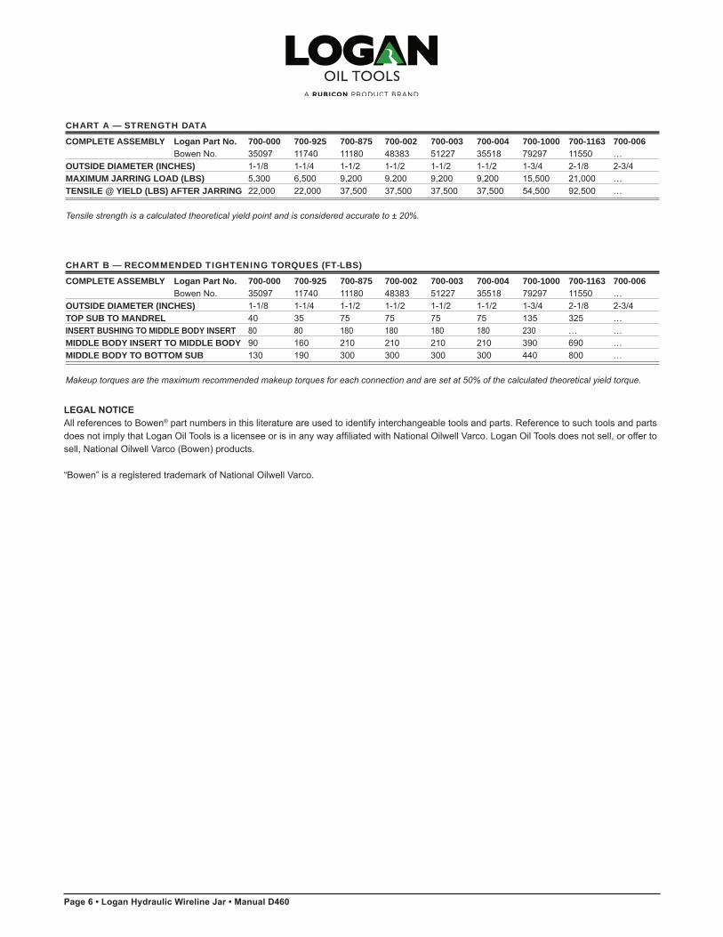
CHART A — STRENGTH DATA
COMPLETE ASSEMBLY Logan Part No. 700-000 700-925 700-875 700-002 700-003 700-004 700-1000 700-1163 700-006 Bowen No. 35097 11740 11180 48383 51227 35518 79297 11550 …OUTSIDE DIAMETER (INCHES) 1-1/8 1-1/4 1-1/2 1-1/2 1-1/2 1-1/2 1-3/4 2-1/8 2-3/4MAXIMUM JARRING LOAD (LBS) 5,300 6,500 9,200 9.200 9,200 9,200 15,500 21,000 …TENSILE @ YIELD (LBS) AFTER JARRING 22,000 22,000 37,500 37,500 37,500 37,500 54,500 92,500 …
Tensile strength is a calculated theoretical yield point and is considered accurate to ± 20%.
CHART B — RECOMMENDED TIGHTENING TORQUES (FT-LBS)
COMPLETE ASSEMBLY Logan Part No. 700-000 700-925 700-875 700-002 700-003 700-004 700-1000 700-1163 700-006 Bowen No. 35097 11740 11180 48383 51227 35518 79297 11550 …OUTSIDE DIAMETER (INCHES) 1-1/8 1-1/4 1-1/2 1-1/2 1-1/2 1-1/2 1-3/4 2-1/8 2-3/4TOP SUB TO MANDREL 40 35 75 75 75 75 135 325 …INSERT BUSHING TO MIDDLE BODY INSERT 80 80 180 180 180 180 230 … …MIDDLE BODY INSERT TO MIDDLE BODY 90 160 210 210 210 210 390 690 …MIDDLE BODY TO BOTTOM SUB 130 190 300 300 300 300 440 800 …
Makeup torques are the maximum recommended makeup torques for each connection and are set at 50% of the calculated theoretical yield torque.
6 • Logan Hydraulic Wireline Jar
LEGAL NOTICEAll references to Bowen® part numbers in this literature are used to identify interchangeable tools and parts. Reference to such tools and parts does not imply that Logan Oil Tools is a licensee or is in any way affiliated with National Oilwell Varco. Logan Oil Tools does not sell, or offer to sell, National Oilwell Varco (Bowen) products.
“Bowen” is a registered trademark of National Oilwell Varco.

Manual D460 • Logan Hydraulic Wireline Jar • Page 7
Recommended Spare Parts:(1) 1 Balanced Piston(2) 2 Valve Plugs (3) 4 Valve Plug Springs (4) 2 Valve Plug Seats (5) 6 Mandrel Non-Extrusion Rings (6) 6 Mandrel Seal Protector Rings (7) 4 Balance Piston Non-Extrusion Rings (8) 4 Balance Piston Seal Protector Rings (9) 6 Complete Packing Sets
HYDRAULIC WIRELINE JAR
OUTSIDE DIAMETER 1-1/8 1-1/4 1-1/2 1-1/2 1-1/2 1-1/2 1-3/4CONNECTIONS 5/8 15/16 15/16 15/16 15/16 15/16 3/4 PIN UP - BOX DOWN 11 THD 10 THD 10 THD 10 THD 10 THD 10 THD SR LENGTH OF STROKE 6-3/4 9-1/4 8-3/4 8-3/4 20 12 10 COMPLETE ASSEMBLY Logan Part No. 700-000 700-925 700-875 700-002 700-003 700-004 700-1000 Bowen No. 35097 11740 11180 48383 51227 35518 79297
TOP SUB Logan Part No. AL1000 AL1001 AL1002 AL1002 AL1002 AL1002 AL1003 Bowen No. 35098 11741 10761 10761 10761 10761 12761MIDDLE BODY Logan Part No. AL2000 AL2001 AL2002 AL2002 AL2003 AL2004 AL2005 Bowen No. 35099 11744 11182 11182 51228 35519 12765MIDDLE BODY INSERT Logan Part No. AL3000 AL3001 AL3002 AL3002 AL3002 AL3002 AL3003 Bowen No. 35100 29486 28652 28652 28652 28652 79298INSERT BUSHING Logan Part No. AL4000 AL4001 AL4002 AL4003 AL4002 AL4003 AL4006 Bowen No. 35101 33572 33571 35085 33571 35085 79299MANDREL Logan Part No. AL5000 AL5001 AL5002 AL5003 AL5004 AL5005 AL5006 Bowen No. 35102 11742 11184 35086 51229 35520 79300BOTTOM SUB Logan Part No. AL6000 AL6001 AL6002 AL6002 AL6002 AL6002 AL6003 Bowen No. 35103 11747 11181 11181 11181 11181 12767
Logan Oil Tools reserves the right to change or discontinue designs without notice.
When ordering, please specify:(1) Name and number of assembly or part (2) Connections, if other than standard
Logan Hydraulic Wireline Jar • 7
LEGAL NOTICEAll references to Bowen® part numbers in this literature are used to identify interchangeable tools and parts. Reference to such tools and parts does not imply that Logan Oil Tools is a licensee or is in any way affiliated with National Oilwell Varco. Logan Oil Tools does not sell, or offer to sell, National Oilwell Varco (Bowen) products.
“Bowen” is a registered trademark of National Oilwell Varco.

Page 8 • Logan Hydraulic Wireline Jar • Manual D460
HYDRAULIC WIRELINE JAR
OUTSIDE DIAMETER 1-1/8 1-1/4 1-1/2 1-1/2 1-1/2 1-1/2 1-3/4CONNECTIONS 5/8 15/16 15/16 15/16 15/16 15/16 3/4 PIN UP - BOX DOWN 11 THD 10 THD 10 THD 10 THD 10 THD 10 THD SR LENGTH OF STROKE 6-3/4 9-1/4 8-3/4 8-3/4 20 12 10 COMPLETE ASSEMBLY Logan Part No. 700-000 700-925 700-875 700-002 700-003 700-004 700-1000 Bowen No. 35097 11740 11180 48383 51227 35518 79297
BALANCE PISTON Logan Part No. AL7000 AL7001 AL7002 AL7002 AL7002 AL7002 AL7003 Bowen No. 35104 11746 11185 11185 11185 11185 12766VALVE PLUG Logan Part No. AL8000 AL8000 AL8000 AL8000 AL8000 AL8000 AL8000 Bowen No. 11189 11189 11189 11189 11189 11189 11189VALVE PLUG SPRING Logan Part No. AL9000 AL9000 AL9000 AL9000 AL9000 AL9000 AL9000 Bowen No. 834 834 834 834 834 834 834VALVE PLUG SEAT Logan Part No. AL10000 AL10000 AL10001 AL10001 AL10001 AL10001 AL10001 Bowen No. 11745 11745 11186 11186 11186 11186 11186FILL PLUG Logan Part No. AG10004 AG10000 AG10000 AG10000 AG10000 AG10000 AG10000 Bowen No. 39941 617 617 617 617 617 617LOCK PIN Logan Part No. AL11000 AL11001 AL11002 AL11002 AL11002 AL11002 AL11003 Bowen No. 15136 16010 13432 13432 13432 13432 18183SPRING GUIDE Logan Part No. AL16000 AL16000 AL16000 AL16000 AL16000 AL16000 AL16000 Bowen No. 48307 48307 48307 48307 48307 48307 48307MANDREL Logan Part No. L365-11 L365-11 L365-15 L365-15 L365-15 L365-15 L365-17NON-EXTRUSION RING Bowen No. 365-11 365-11 365-15 365-15 365-15 365-15 365-17 No. Req’d 2 2 2 2 2 2 2 MANDREL SEAL Logan Part No. L375-11 L375-11 L375-15 L375-15 L375-15 L375-15 L375-17PROTECTOR RING Bowen No. 375-11 375-11 375-15 375-15 375-15 375-15 375-17 No. Req’d 2 2 2 2 2 2 2BALANCE PISTON Logan Part No. L366-11 L366-11 L366-16 L366-16 L366-16 L366-16 L366-20NON-EXTRUSION RING Bowen No. 366-11 366-11 366-16 366-16 366-16 366-16 366-20 No. Req’d 2 2 2 2 2 2 2BALANCE PISTON SEAL Logan Part No. L82-11 L82-11 L82-16 L82-16 L82-16 L82-16 L82-20PROTECTOR RING Bowen No. 82-11 82-11 82-16 82-16 82-16 82-16 82-20 No. Req’d 2 2 2 2 2 2 2
Logan Oil Tools reserves the right to change or discontinue designs without notice.
When ordering, please specify:(1) Name and number of assembly or part (2) Connections, if other than standard
Recommended Spare Parts: (1) 1 Balanced Piston(2) 2 Valve Plugs (3) 4 Valve Plug Springs (4) 2 Valve Plug Seats (5) 6 Mandrel Non-Extrusion Rings (6) 6 Mandrel Seal Protector Rings (7) 4 Balance Piston Non-Extrusion Rings (8) 4 Balance Piston Seal Protector Rings (9) 6 Complete Packing Sets
8 • Logan Hydraulic Wireline Jar
LEGAL NOTICEAll references to Bowen® part numbers in this literature are used to identify interchangeable tools and parts. Reference to such tools and parts does not imply that Logan Oil Tools is a licensee or is in any way affiliated with National Oilwell Varco. Logan Oil Tools does not sell, or offer to sell, National Oilwell Varco (Bowen) products.
“Bowen” is a registered trademark of National Oilwell Varco.

Manual D460 • Logan Hydraulic Wireline Jar • Page 9
HYDRAULIC WIRELINE JAR
OUTSIDE DIAMETER 1-1/8 1-1/4 1-1/2 1-1/2 1-1/2 1-1/2 1-3/4CONNECTIONS 5/8 15/16 15/16 15/16 15/16 15/16 3/4 PIN UP - BOX DOWN 11 THD 10 THD 10 THD 10 THD 10 THD 10 THD SR LENGTH OF STROKE 6-3/4 9-1/4 8-3/4 8-3/4 20 12 10 COMPLETE ASSEMBLY Logan Part No. 700-000 700-001 700-875 700-002 700-003 700-004 700-1000 Bowen No. 35097 11740 11180 48383 51227 35518 79297
VITON O-RING PACKING SET Logan Part No. 28000-008 28000-009 28000-010 28000-010 28000-010 28000-010 28000-011Consists of: Bowen No. 35106 11754 11191 11191 11191 11191 79327MANDREL SEAL Logan Part No. 568-112 568-112 568-210 568-210 568-210 568-210 568-212 Bowen No. 568112 568112 568210 568210 568210 568210 568212BALANCE PISTON SEAL Logan Part No. 568-113 568-113 568-211 568-211 568-211 568-211 568-215 Bowen No. 568113 568113 568211 568211 568211 568211 568215MIDDLE BODY Logan Part No. 568-116 568-116 568-215 568-215 568-215 568-215 568-218INSERT SEAL (LARGE) Bowen No. 568116 568116 568215 568215 568215 568215 568218MIDDLE BODY Logan Part No. … … … … … … …INSERT SEAL (SMALL) Bowen No. … … … … … … …VALVE PLUG SEAL Logan Part No. 568-007 568-007 568-007 568-007 568-007 568-007 568-007 Bowen No. 568007 568007 568007 568007 568007 568007 568007VALVE PLUG Logan Part No. 568-110 568-110 568-112 568-112 568-112 568-112 568-112SEAT SEAL Bowen No. 568110 568110 568112 568112 568112 568112 568112FILL PLUG SEAL Logan Part No. … 568-005 568-005 568-005 568-005 568-005 568-005 Bowen No. … 568005 568005 568005 568005 568005 568005
ACCESSORIES
SERVICE KIT Logan Part No. 28001-013 28001-014 28001-015 28001-015 28001-015 28001-015 28001-016 Bowen No. 35105 11751 11178 11178 11178 11178 15997MANDREL BODY Logan Part No. AG1000-10 AG1000-11 AG1000-15 AG1000-15 AG1000-15 AG1000-15 AG1000-17SETTING TOOL Bowen No. 22709-10 22709-11 22709-15 22709-15 22709-15 22709-15 22709-17BALANCE PISTON Logan Part No. AL13000-11 AL13001 AL13000-16 AL13000-16 AL13000-16 AL13000-16 AL13000-20SETTING TOOL Bowen No. 22729-11 11753 22729-16 22729-16 22729-16 22729-16 22729-20
Logan Oil Tools reserves the right to change or discontinue designs without notice.
When ordering, please specify:(1) Name and number of assembly or part (2) Connections, if other than standard
Recommended Spare Parts: (1) 1 Balanced Piston(2) 2 Valve Plugs (3) 4 Valve Plug Springs (4) 2 Valve Plug Seats (5) 6 Mandrel Non-Extrusion Rings (6) 6 Mandrel Seal Protector Rings (7) 4 Balance Piston Non-Extrusion Rings (8) 4 Balance Piston Seal Protector Rings (9) 6 Complete Packing Sets
Logan Hydraulic Wireline Jar • 9
LEGAL NOTICEAll references to Bowen® part numbers in this literature are used to identify interchangeable tools and parts. Reference to such tools and parts does not imply that Logan Oil Tools is a licensee or is in any way affiliated with National Oilwell Varco. Logan Oil Tools does not sell, or offer to sell, National Oilwell Varco (Bowen) products.
“Bowen” is a registered trademark of National Oilwell Varco.

Page 10 • Logan Hydraulic Wireline Jar • Manual D460
HYDRAULIC WIRELINE JAR
OUTSIDE DIAMETER 2-1/8 2-3/4CONNECTIONS 7/8 1-9/16PIN UP - BOX DOWN SR 10 THDLENGTH OF STROKE (INCHES) 11-5/8 20COMPLETE ASSEMBLY Logan Part No. 700-1163 700-006 Bowen No. 11550 …
TOP SUB Logan Part No. AL1004 AL1005 Bowen No. 11543 …MIDDLE BODY Logan Part No. AL2006 AL2007 Bowen No. 11537 …MIDDLE BODY INSERT Logan Part No. AL3004 AL3005 Bowen No. 11538 …INSERT BUSHING Logan Part No. … … Bowen No. … …MANDREL Logan Part No. AL5007 AL5008 Bowen No. 11539 …BOTTOM SUB Logan Part No. AL6004 AL6005 Bowen No. 11536 …BALANCE PISTON Logan Part No. AL7004 AL7005 Bowen No. 11540 …VALVE PLUG Logan Part No. AL8000 AL8001 Bowen No. 11189 …VALVE PLUG SPRING Logan Part No. AL9000 AL9001 Bowen No. 834 …VALVE PLUG SEAT Logan Part No. AL10001 AL10002 Bowen No. 11186 …FILL PLUG Logan Part No. AG10002 AG10003 Bowen No. 329 …LOCK PIN Logan Part No. AL11004 AL11005 Bowen No. 42732 …SPRING GUIDE Logan Part No. AL16000 AL16001 Bowen No. 48307 …
Logan Oil Tools reserves the right to change or discontinue designs without notice.
When ordering, please specify:(1) Name and number of assembly or part (2) Connections, if other than standard
Recommended Spare Parts: (1) 1 Balanced Piston(2) 2 Valve Plugs (3) 4 Valve Plug Springs (4) 2 Valve Plug Seats (5) 6 Mandrel Non-Extrusion Rings (6) 6 Mandrel Seal Protector Rings (7) 4 Balance Piston Non-Extrusion Rings (8) 4 Balance Piston Seal Protector Rings (9) 6 Complete Packing Sets
10 • Logan Hydraulic Wireline Jar
LEGAL NOTICEAll references to Bowen® part numbers in this literature are used to identify interchangeable tools and parts. Reference to such tools and parts does not imply that Logan Oil Tools is a licensee or is in any way affiliated with National Oilwell Varco. Logan Oil Tools does not sell, or offer to sell, National Oilwell Varco (Bowen) products.
“Bowen” is a registered trademark of National Oilwell Varco.

Manual D460 • Logan Hydraulic Wireline Jar • Page 11
HYDRAULIC WIRELINE JAR
OUTSIDE DIAMETER 2-1/8 2-3/4CONNECTIONS 7/8 1-9/16PIN UP - BOX DOWN SR 10 THDLENGTH OF STROKE (INCHES) 6-3/4 20COMPLETE ASSEMBLY Logan Part No. 700-1163 700-006 Bowen No. 11550 …
MANDREL Logan Part No. L365-21 L365-27NON-EXTRUSION RING Bowen No. 365-21 365-27 No. Req’d 2 2MANDREL SEAL Logan Part No. L375-21 L375-27PROTECTOR RING Bowen No. 375-21 375-27 No. Req’d 2 2BALANCE PISTON Logan Part No. L366-24 L366-28.5NON-EXTRUSION RING Bowen No. 366-24 … No. Req’d 2 2BALANCE PISTON SEAL Logan Part No. L82-24 8-235PROTECTOR RING Bowen No. 82-24 … No. Req’d 2 2
Logan Oil Tools reserves the right to change or discontinue designs without notice.
When ordering, please specify:(1) Name and number of assembly or part (2) Connections, if other than standard
Recommended Spare Parts: (1) 1 Balanced Piston(2) 2 Valve Plugs (3) 4 Valve Plug Springs (4) 2 Valve Plug Seats (5) 6 Mandrel Non-Extrusion Rings (6) 6 Mandrel Seal Protector Rings (7) 4 Balance Piston Non-Extrusion Rings (8) 4 Balance Piston Seal Protector Rings (9) 6 Complete Packing Sets
Logan Hydraulic Wireline Jar • 11
LEGAL NOTICEAll references to Bowen® part numbers in this literature are used to identify interchangeable tools and parts. Reference to such tools and parts does not imply that Logan Oil Tools is a licensee or is in any way affiliated with National Oilwell Varco. Logan Oil Tools does not sell, or offer to sell, National Oilwell Varco (Bowen) products.
“Bowen” is a registered trademark of National Oilwell Varco.
Page 12 • Logan Hydraulic Wireline Jar • Manual D460
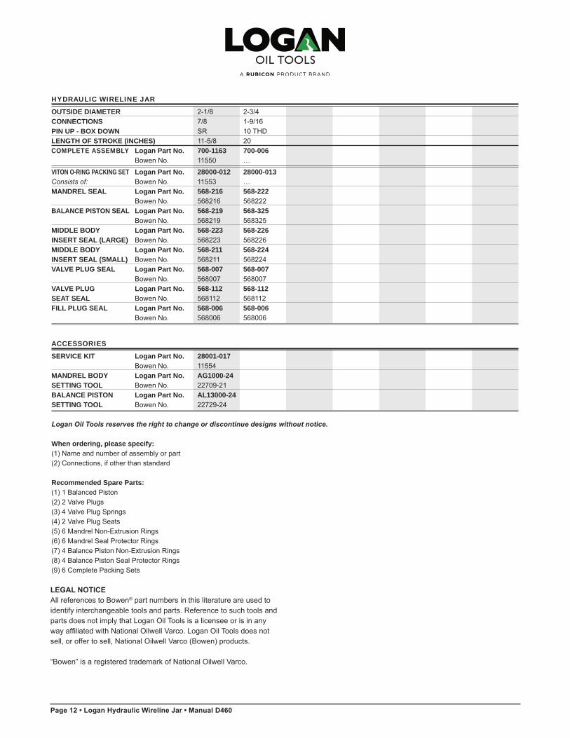
HYDRAULIC WIRELINE JAR
OUTSIDE DIAMETER 2-1/8 2-3/4 CONNECTIONS 7/8 1-9/16 PIN UP - BOX DOWN SR 10 THD LENGTH OF STROKE (INCHES) 11-5/8 20COMPLETE ASSEMBLY Logan Part No. 700-1163 700-006 Bowen No. 11550 …
VITON O-RING PACKING SET Logan Part No. 28000-012 28000-013Consists of: Bowen No. 11553 … MANDREL SEAL Logan Part No. 568-216 568-222 Bowen No. 568216 568222 BALANCE PISTON SEAL Logan Part No. 568-219 568-325 Bowen No. 568219 568325 MIDDLE BODY Logan Part No. 568-223 568-226INSERT SEAL (LARGE) Bowen No. 568223 568226 MIDDLE BODY Logan Part No. 568-211 568-224INSERT SEAL (SMALL) Bowen No. 568211 568224 VALVE PLUG SEAL Logan Part No. 568-007 568-007 Bowen No. 568007 568007VALVE PLUG Logan Part No. 568-112 568-112SEAT SEAL Bowen No. 568112 568112 FILL PLUG SEAL Logan Part No. 568-006 568-006 Bowen No. 568006 568006
ACCESSORIES
SERVICE KIT Logan Part No. 28001-017 Bowen No. 11554 MANDREL BODY Logan Part No. AG1000-24SETTING TOOL Bowen No. 22709-21 BALANCE PISTON Logan Part No. AL13000-24SETTING TOOL Bowen No. 22729-24
Logan Oil Tools reserves the right to change or discontinue designs without notice.
When ordering, please specify:(1) Name and number of assembly or part (2) Connections, if other than standard
Recommended Spare Parts: (1) 1 Balanced Piston(2) 2 Valve Plugs (3) 4 Valve Plug Springs (4) 2 Valve Plug Seats (5) 6 Mandrel Non-Extrusion Rings (6) 6 Mandrel Seal Protector Rings (7) 4 Balance Piston Non-Extrusion Rings (8) 4 Balance Piston Seal Protector Rings (9) 6 Complete Packing Sets
12 • Logan Hydraulic Wireline Jar
LEGAL NOTICEAll references to Bowen® part numbers in this literature are used to identify interchangeable tools and parts. Reference to such tools and parts does not imply that Logan Oil Tools is a licensee or is in any way affiliated with National Oilwell Varco. Logan Oil Tools does not sell, or offer to sell, National Oilwell Varco (Bowen) products.
“Bowen” is a registered trademark of National Oilwell Varco.

©2014 Logan Oil Tools12/2014
CORPORATE HEADQUARTERS
Logan International Inc. 7850 North Sam Houston Parkway West, Suite 100Houston, Texas 77064+1 832 386 2500
635 8th Avenue SouthwestSuite 850Calgary, Canada T2P 3M3 403 930 6810 | Fax 403 930 6811
U.S. SALES OFFICES
California 3155 Pegasus Drive Bakersfield, CA 93308-6800 661.387.1449 I Fax 661.387.1624
Louisiana 103 Bluffwood Drive Broussard , LA 70518-3310 337.839.2331 I Fax 337.839.2334
118 Common Court Houma, LA 70360-7982 985.868.7333 I Fax 985.868.7007
North Dakota 4925 Highway 85 South Williston , ND 58801 701.572.0565 I Fax 701.572.0644
Oklahoma 424 South Eagle Lane Oklahoma City, OK 73128-4225 405.782.0625 I Fax 405.782.0760
Pennsylvania 244 Grey Fox Drive, Suite 1 Montoursville , PA 17754-9572 570.546.1066 I Fax 570.546.0388
Texas 1519 South Flournoy Alice TX,78332 361.396.0139 I Fax 361.396.0112
11610 Cutten Road Houston, TX 77066-3008 832.602.2134 I Fax 832.286.4117
11006 Lucerne Street Houston, Texas 77016-1920 281.219.6613 I Fax 281.219.6638
1305 Energy Drive Kilgore, TX 75662-5539 903.984.6700 I Fax 903.984.6755
601 McDonald Odessa, TX 79761-6106 432.580.7414 I Fax 432.580.7656
Utah 1369 South 1100 East Vernal, UT 84078-8600 435.781.2856 I Fax 435.781.2858
INTERNATIONAL STOCKING DISTRIBUTORS
Canada Logan Oil Tools 9755 45th Avenue NW Edmonton , Alberta T6E 5V8 780.433.9957 I Fax 780.468.1979
Colombia Logan Oil Tools Sucursal Colombia Calle 113 No. 7-21 Edificio Teleport Business Park Torre A, Oficina 915 Bogota, Colombia (57.1 ).629.1995 I Fax (57.1 ).612.8357
A Singapore Logan Oil Tools Pte Ltd 54 Loyang Way Singapore 508747 65.65428422 I Fax 65.65420477
United Arab Emirates Logan Oil Tools Jebel Ali Free Zone (South) P.O. Box 23724 Dubai, UAE 971.4.813.8000 I Fax 971.4.813.8001
Woodhouse International P.O. Box 23724 Dubai, UAE 971.4.347.2300 I Fax 971.4.347.4642
United Kingdom Logan Oil Tools, U.K. Ltd. Unit C1 Kintore Business Park Kintore, lnverurie Aberdeenshire AB51 OYQ Scotland +44.1467.631190