lecture-2 properties of enginerring materials
DESCRIPTION
Propriedades de engenharia dos materiais, baseado no GrooverTRANSCRIPT
1
1
Dr. Luis César R. Aliaga
Processos de Fabricação I ou / or
Manufacturing Process I
IPRJ Universidade do estado do Rio de Janeiro
PROPERTIES OF ENGINEERING MATERIALS
1. Stress-strain relationships 2. Hardness 3. Effect of temperature on mechanical properties 4. Volumetric and melting properties 5. Thermal properties
2
Mechanical Properties in Design and Manufacturing
§ Mechanical properties determine a material’s behavior when subjected to mechanical stresses
§ Properties include elastic modulus, ductility, hardness, and various measures of strength
§ Dilemma: mechanical properties that are desirable to the designer, such as high strength, usually make manufacturing more difficult
Stress‑Strain Relationships
§ Three types of static stresses to which materials can be subjected:
1. Tensile - stretching the material
2. Compressive - squeezing the material
3. Shear - causing adjacent portions of the material to slide against each other
§ Stress‑strain curve - basic relationship that describes mechanical properties for all three types
3
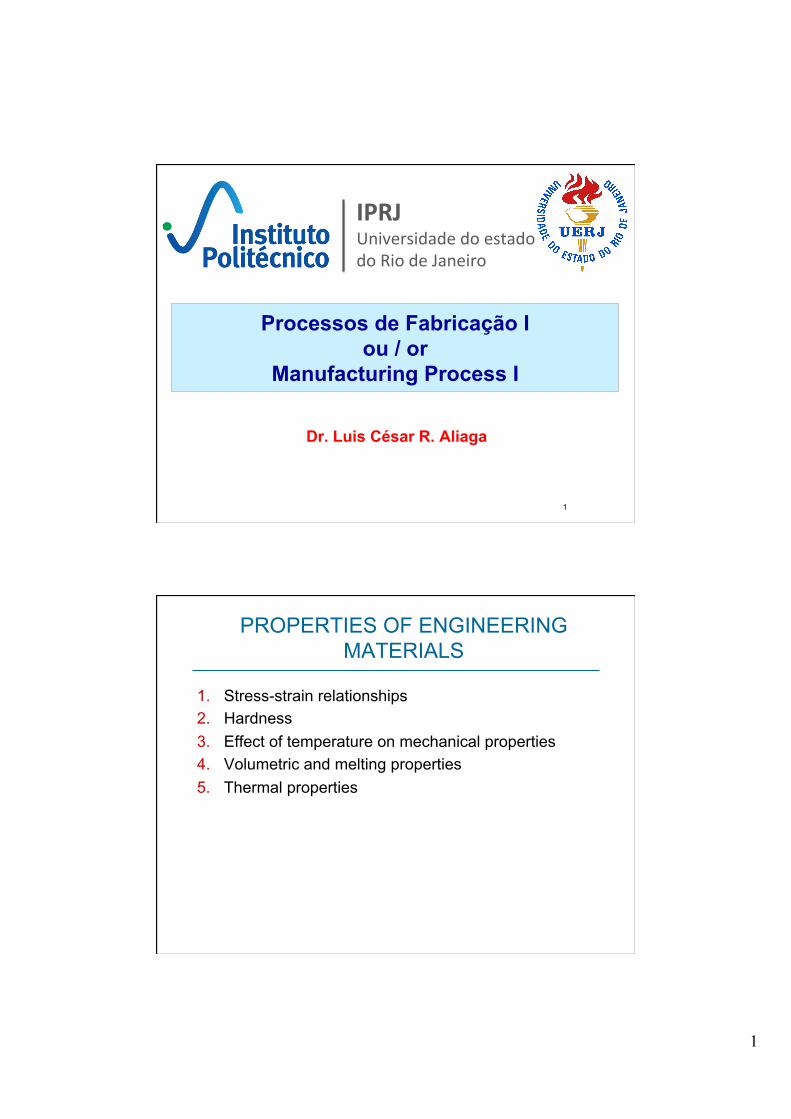
Tensile Test
§ Most common test for studying stress‑strain relationship, especially metals
§ In the test, a force pulls the material, elongating it and reducing its diameter
§ (left) Tensile force applied and (right) resulting elongation of material
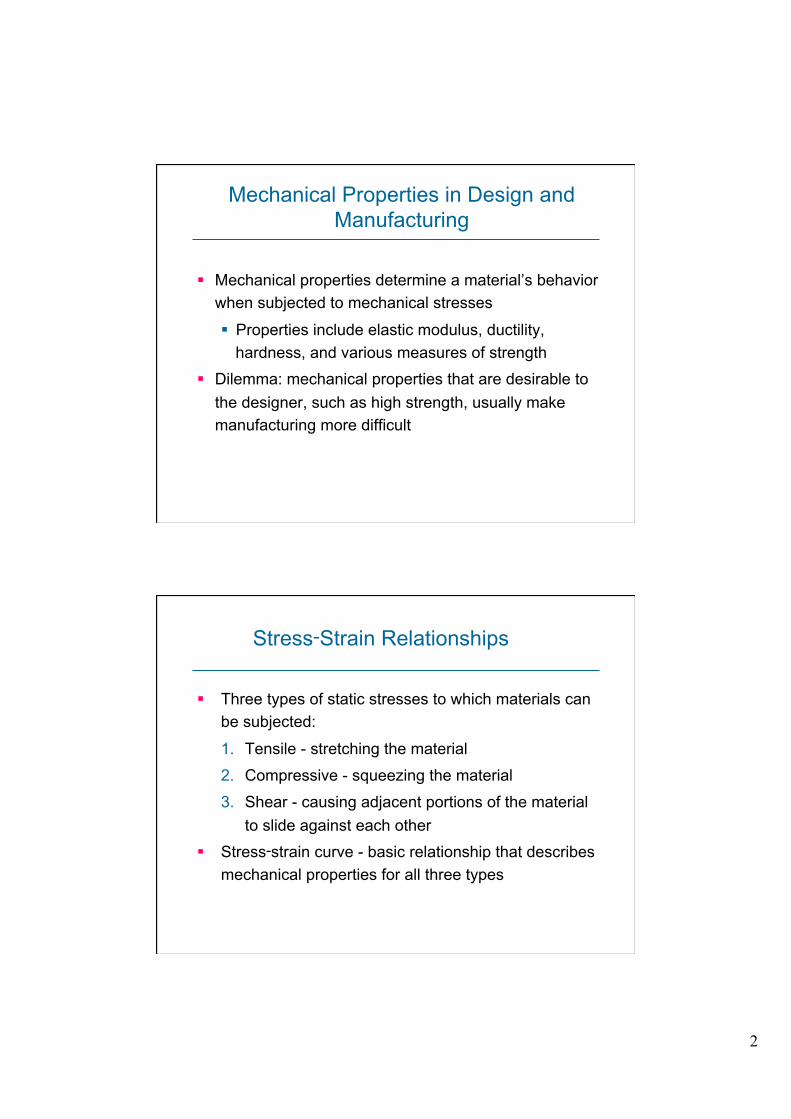
Tensile Test Specimen
§ ASTM (American Society for Testing and Materials) specifies preparation of test specimen
4
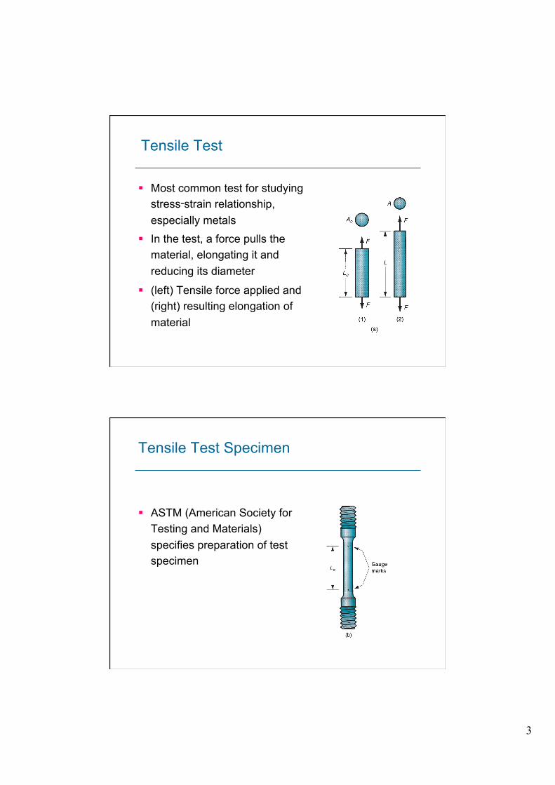
Tensile Test Setup
§ Tensile testing machine
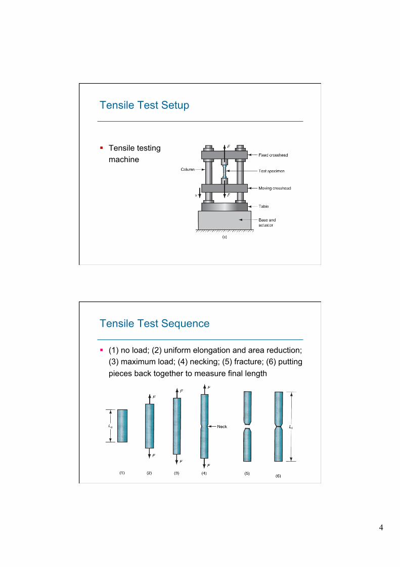
Tensile Test Sequence
§ (1) no load; (2) uniform elongation and area reduction; (3) maximum load; (4) necking; (5) fracture; (6) putting pieces back together to measure final length
5
Engineering Stress
Defined as force divided by original area:
oe A
F=σ
where e = engineering stress, F = applied force, and Ao = original area of test specimen
Engineering Strain
Defined at any point in the test as
where e = engineering strain; L = length at any point during elongation; and Lo = original gage length
o
oLLLe −=

6
Typical Engineering Stress-Strain Plot
§ Typical engineering stress‑strain plot in a tensile test of a metal
§ Two regions:
1. Elastic region
2. Plastic region
Carga máxima
Ruptura
Limite de desvio
Tensão de escoamento
Tensão ultima ou limite de resistência
Elastic Region in Stress‑Strain Curve
§ Relationship between stress and strain is linear Hooke's Law: e = E e
where E = modulus of elasticity
§ Material returns to its original length when stress is removed
§ E is a measure of the inherent stiffness of a material
§ Its value differs for different materials
7
Yield Point in Stress‑Strain Curve
§ As stress increases, a point in the linear relationship is finally reached when the material begins to yield
§ Yield point Y can be identified by the change in slope at the upper end of the linear region § Y = a strength property
§ Other names for yield point:
§ Yield strength
§ Yield stress
§ Elastic limit
Ponto de escoamento
Plastic Region in Stress‑Strain Curve
§ Yield point marks the beginning of plastic deformation § The stress-strain relationship is no longer guided by
Hooke's Law
§ As load is increased beyond Y, elongation proceeds at a much faster rate than before, causing the slope of the curve to change dramatically
8
Tensile Strength in Stress‑Strain Curve
§ Elongation is accompanied by a uniform reduction in cross‑sectional area, consistent with maintaining constant volume
§ Finally, the applied load F reaches a maximum value, and engineering stress at this point is called the tensile strength TS (a.k.a. ultimate tensile strength)
TS = oA
Fmax
Ductility in Tensile Test
§ Ability of a material to plastically strain without fracture § Ductility measure = elongation EL
where EL = elongation; Lf = specimen length at fracture; and Lo = original specimen length Lf is measured as the distance between gage marks after two pieces of specimen are put back together
o
ofLLLEL −=

9
True Stress
Stress value obtained by dividing the instantaneous area into applied load
where = true stress; F = force; and A = actual (instantaneous) area resisting the load
AF=σ
True Strain
§ Provides a more realistic assessment of "instantaneous" elongation per unit length
ε = dLLLo
L
∫ = ln LLo
10
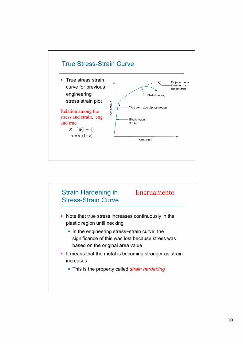
True Stress-Strain Curve
§ True stress‑strain curve for previous engineering stress‑strain plot
ε = ln(1+ e)σ =σ e(1+ e)
Relation among the stress and strain, eng. and true.
Strain Hardening in Stress-Strain Curve
§ Note that true stress increases continuously in the plastic region until necking
§ In the engineering stress-strain curve, the significance of this was lost because stress was based on the original area value
§ It means that the metal is becoming stronger as strain increases
§ This is the property called strain hardening
Encruamento
11
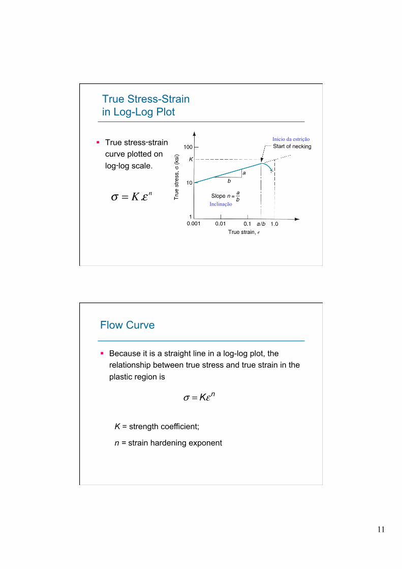
True Stress-Strain in Log-Log Plot
§ True stress‑strain curve plotted on log‑log scale.
Inicio da estrição
Inclinação σ = K .ε n
Flow Curve
§ Because it is a straight line in a log-log plot, the relationship between true stress and true strain in the plastic region is
K = strength coefficient;
n = strain hardening exponent
nKεσ =

12
Categories of Stress-Strain Relationship: Perfectly Elastic
§ Behavior is defined completely by modulus of elasticity E
§ Fractures rather than yielding to plastic flow
§ Brittle materials: ceramics, many cast irons, and thermosetting polymers
Stress-Strain Relationships: Elastic and Perfectly Plastic
§ Stiffness defined by E § Once Y reached, deforms
plastically at same stress level
§ Flow curve: K = Y, n = 0
§ Metals behave like this when heated to sufficiently high temperatures (above recrystallization)
13
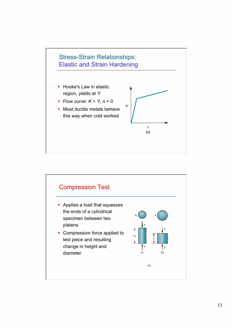
Stress-Strain Relationships: Elastic and Strain Hardening
§ Hooke's Law in elastic region, yields at Y
§ Flow curve: K > Y, n > 0
§ Most ductile metals behave this way when cold worked
Compression Test
§ Applies a load that squeezes the ends of a cylindrical specimen between two platens
§ Compression force applied to test piece and resulting change in height and diameter
14
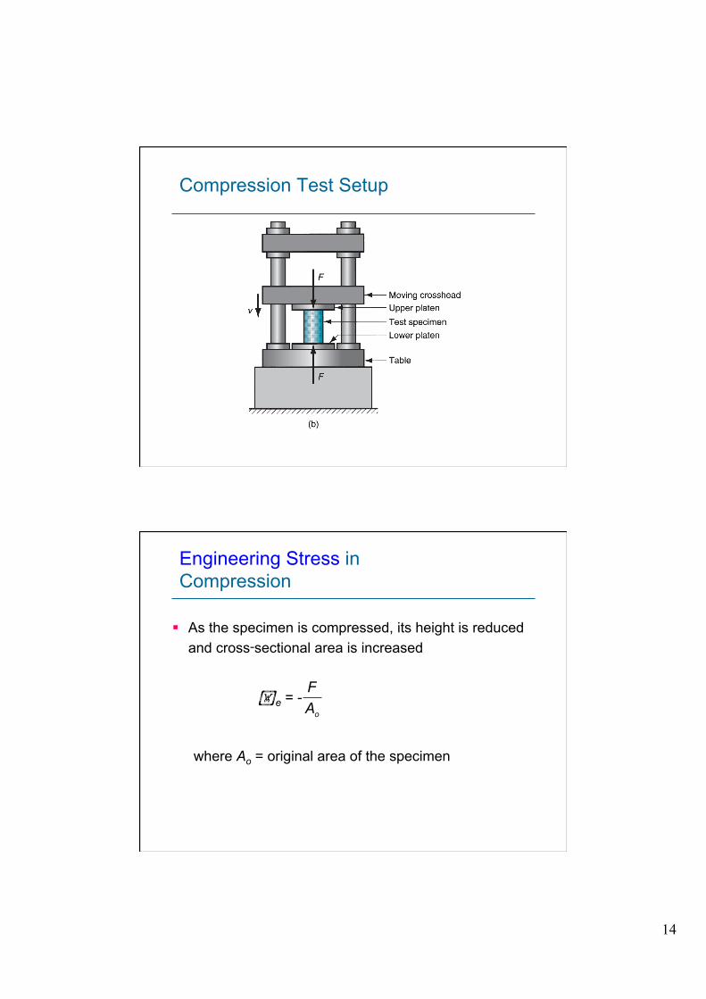
Compression Test Setup
Engineering Stress in Compression
§ As the specimen is compressed, its height is reduced and cross‑sectional area is increased
e = -
where Ao = original area of the specimen
oAF

15
Engineering Strain in Compression
Engineering strain is defined
Since height is reduced during compression, value of e is negative (the negative sign is usually ignored when expressing compression strain)
o
ohhhe −=
Stress-Strain Curve in Compression
§ Shape of plastic region is different from tensile test because cross section increases
§ Calculated value of engineering stress is higher
16
Tensile Test vs. Compression Test
§ Although differences exist between engineering stress‑strain curves in tension and compression, the true stress‑strain relationships are nearly identical
§ Since tensile test results are more common, flow curve values (K and n) from tensile test data can be applied to compression operations
§ When using tensile K and n data for compression, ignore necking, which is a phenomenon peculiar to strain induced by tensile stresses
Testing of Brittle Materials
§ Hard brittle materials (e.g., ceramics) possess elasticity but little or no plasticity
§ Conventional tensile test cannot be easily applied
§ Often tested by a bending test (also called flexure test)
§ Specimen of rectangular cross-section is positioned between two supports, and a load is applied at its center
17
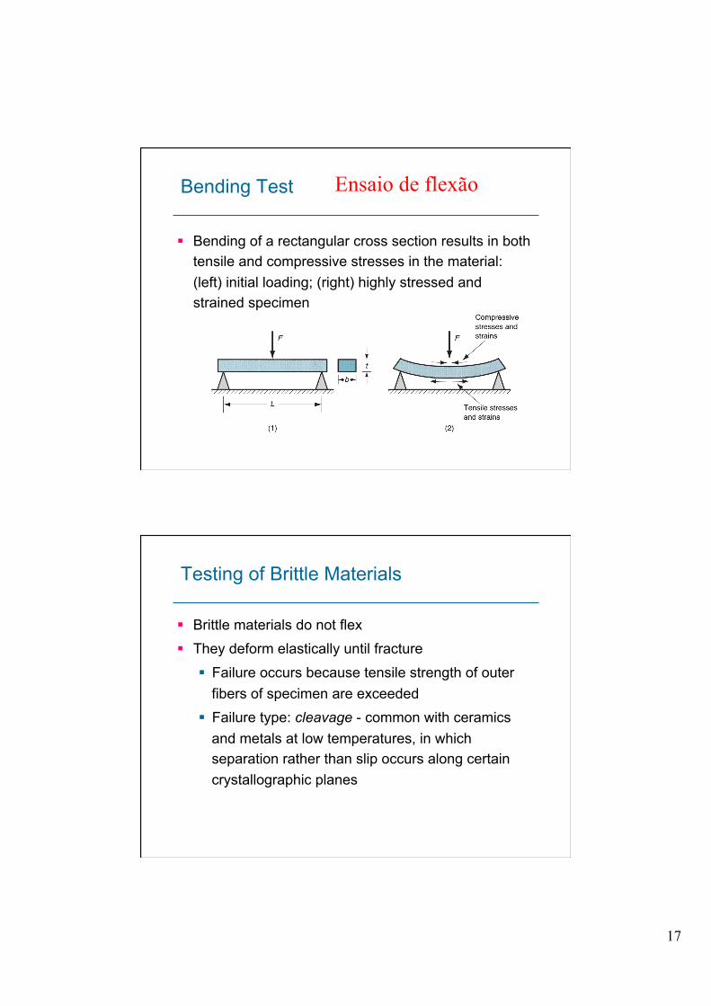
Bending Test
§ Bending of a rectangular cross section results in both tensile and compressive stresses in the material: (left) initial loading; (right) highly stressed and strained specimen
Ensaio de flexão
Testing of Brittle Materials
§ Brittle materials do not flex § They deform elastically until fracture
§ Failure occurs because tensile strength of outer fibers of specimen are exceeded
§ Failure type: cleavage - common with ceramics and metals at low temperatures, in which separation rather than slip occurs along certain crystallographic planes

18
Transverse Rupture Strength
§ The strength value derived from the bending test:
251btFLTRS .=
TRS = transverse rupture strength;
F = applied load at fracture;
L = length of specimen between supports; and b and t are dimensions of cross section
Shear Properties
§ Application of stresses in opposite directions on either side of a thin element: (a) shear stress and (b) shear strain

19
Shear Stress and Strain
Shear stress defined as
F = applied force; and A = area over which deflection occurs.
Shear strain defined as
= deflection element; and b = distance over which deflection occurs
AF=τ
bδγ =
Torsion Stress-Strain Curve
§ Typical shear stress‑strain curve from a torsion test
20
Shear Elastic Stress‑Strain Relationship
§ In the elastic region, the relationship is defined as
γτ G=
where G = shear modulus, or shear modulus of elasticity
For most materials, G 0.4E, where E = elastic modulus
Shear Plastic Stress‑Strain Relationship
§ Relationship similar to flow curve for a tensile test § Shear stress at fracture = shear strength S
§ Shear strength can be estimated from tensile strength: S 0.7(TS)
§ Since cross‑sectional area of test specimen in torsion test does not change as in tensile and compression, engineering stress‑strain curve for shear true stress‑strain curve
21
Hardness
Resistance to permanent indentation § Good hardness generally means material is resistant
to scratching and wear
§ Most tooling used in manufacturing must be hard for scratch and wear resistance
Hardness Tests
§ Commonly used for assessing material properties because they are quick and convenient
§ Variety of testing methods are appropriate due to differences in hardness among different materials
§ Most well‑known hardness tests are Brinell and Rockwell
§ Other test methods are also available, such as Vickers, Knoop, Scleroscope, and durometer
22
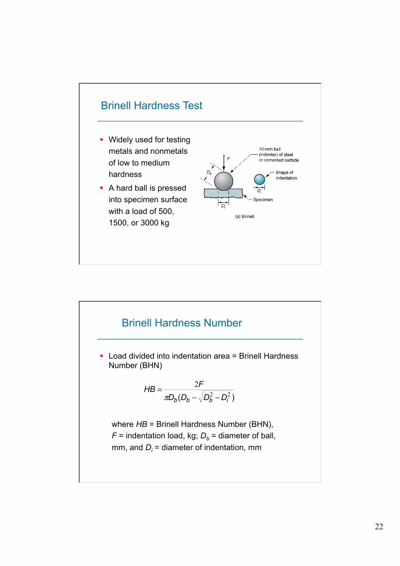
§ Widely used for testing metals and nonmetals of low to medium hardness
§ A hard ball is pressed into specimen surface with a load of 500, 1500, or 3000 kg
Brinell Hardness Test
Brinell Hardness Number
§ Load divided into indentation area = Brinell Hardness Number (BHN)
)( 222
ibbb DDDDFHB
−−=π
where HB = Brinell Hardness Number (BHN), F = indentation load, kg; Db = diameter of ball, mm, and Di = diameter of indentation, mm
23
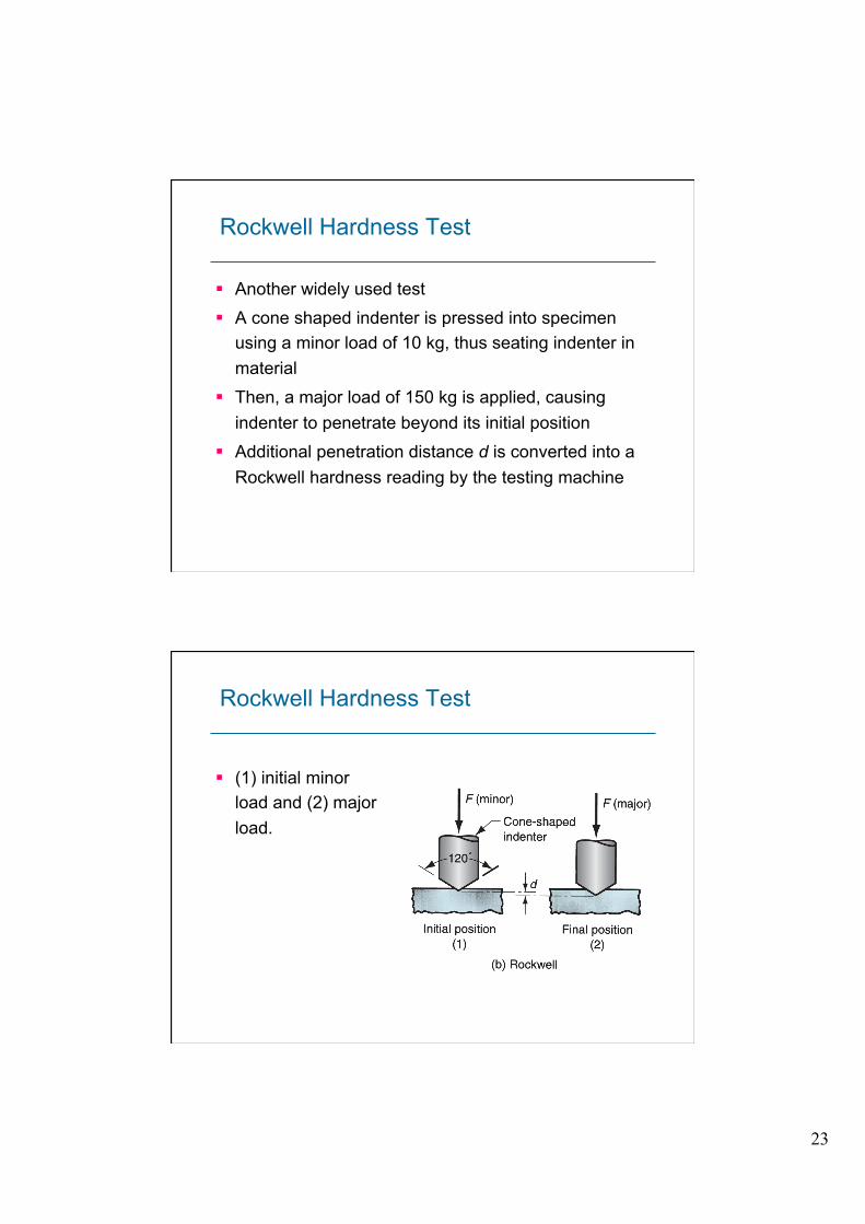
Rockwell Hardness Test
§ Another widely used test § A cone shaped indenter is pressed into specimen
using a minor load of 10 kg, thus seating indenter in material
§ Then, a major load of 150 kg is applied, causing indenter to penetrate beyond its initial position
§ Additional penetration distance d is converted into a Rockwell hardness reading by the testing machine
Rockwell Hardness Test
§ (1) initial minor load and (2) major load.
24
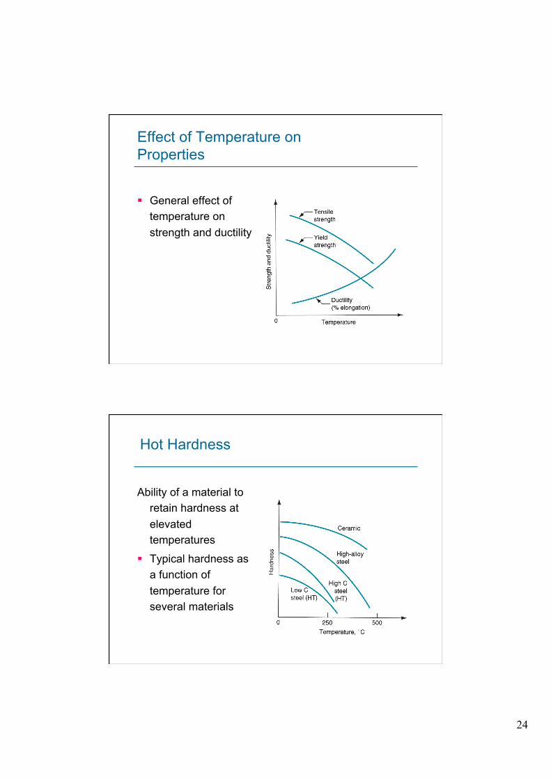
Effect of Temperature on Properties
§ General effect of temperature on strength and ductility
Hot Hardness
Ability of a material to retain hardness at elevated temperatures
§ Typical hardness as a function of temperature for several materials
25
Recrystallization in Metals
§ Most metals strain harden at room temperature according to the flow curve (n > 0)
§ But if heated to sufficiently high temperature and deformed, strain hardening does not occur § Instead, new grains form that are free of strain
§ The metal has recrystallized
§ The metal behaves as a perfectly plastic material; that is, n = 0
Recrystallization Temperature
§ Recrystallization temperature of a given metal = about one‑half its melting point (0.5 Tm) as measured on an absolute temperature scale
§ Recrystallization takes time
§ The recrystallization temperature is specified as the temperature at which new grains are formed in about one hour
26
Recrystallization and Manufacturing
§ Recrystallization can be exploited in manufacturing § Heating a metal to its recrystallization temperature
prior to deformation allows a greater amount of straining § Lower forces and power are required to perform
the process § Forming a metal at temperatures above its
recrystallization temperature is called hot working
Shear Stress
§ Shear stress is the frictional force exerted by the fluid per unit area
§ Motion of the upper plate is resisted by this frictional force resulting from the shear viscosity of the fluid
§ This force F can be reduced to a shear stress by dividing by plate area A
AF=τ
27
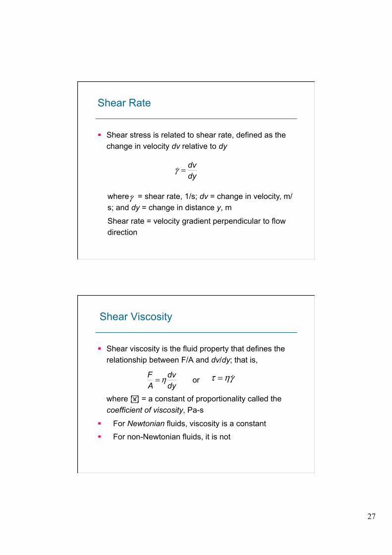
Shear Rate
§ Shear stress is related to shear rate, defined as the change in velocity dv relative to dy
where = shear rate, 1/s; dv = change in velocity, m/s; and dy = change in distance y, m
Shear rate = velocity gradient perpendicular to flow direction
dydv=γ!
γ!
Shear Viscosity
§ Shear viscosity is the fluid property that defines the relationship between F/A and dv/dy; that is,
or
where = a constant of proportionality called the coefficient of viscosity, Pa-s
§ For Newtonian fluids, viscosity is a constant
§ For non-Newtonian fluids, it is not
dydv
AF η= γητ !=
28
Volumetric and Melting Properties
Properties related to the volume of solids and how these properties are affected by temperature
§ Density
§ Thermal expansion
§ Melting point
Density and Specific Gravity
§ Density = weight per unit volume
§ Typical units are g/cm3 (lb/in3)
§ Determined by atomic number and other factors such as atomic radius, and atomic packing
§ Specific gravity = density of a material relative to density of water
§ Ratio with no units
29
Why Density is Important
§ A consideration in material selection for a given application, but it may not be the only property of interest
§ Strength may also be important, and the two properties are often related in a strength‑to‑weight ratio, which is tensile strength divided by density
§ Useful ratio in comparing materials for structural applications in aircraft, automobiles, and other products where weight and energy are concerns
Thermal Expansion
§ Density of a material is a function of temperature
§ In general, density decreases with increasing temperature
§ Volume per unit weight increases with increasing temperature
§ Thermal expansion is the name for this effect of temperature on density
§ Measured as coefficient of thermal expansion
30
Coefficient of Thermal Expansion
Change in length per degree of temperature, such as mm/mm/oC.
§ Length ratio rather than volume ratio because this is easier to measure and apply
§ Change in length for a given temperature change: L2 - L1 = αL1 (T2 - T1)
α = coefficient of thermal expansion;
L1 and L2 are lengths corresponding respectively to temperatures T1 and T2
Thermal Expansion in Manufacturing
§ Thermal expansion is used in shrink fit and expansion fit assemblies
§ Part is heated to increase size or cooled to decrease size to permit insertion into another part
§ When part returns to ambient temperature, a tightly-fitted assembly is obtained
§ Thermal expansion can be a problem in heat treatment and welding due to thermal stresses that develop in material during these processes
31
Melting Characteristics for Elements
Melting point Tm of a pure element = temperature at which it transforms from solid to liquid state
§ The reverse transformation occurs at the same temperature and is called the freezing point
Heat of fusion = heat energy required at Tm to accomplish transformation from solid to liquid
Melting of Metal Alloys
§ Unlike pure metals, most alloys do not have a single melting point
§ Instead, melting begins at a temperature called the solidus and continues as temperature increases until converting completely to liquid at a temperature called the liquidus
§ Between the two temperatures, the alloy is a mixture of solid and molten metals
32
Melting of Noncrystalline Materials
§ In noncrystalline materials (glasses), a gradual transition from solid to liquid states occurs § The solid material gradually softens as
temperature increases, finally becoming liquid at the melting point
§ During softening, the material has a consistency of increasing plasticity (increasingly like a fluid) as it gets closer to the melting point
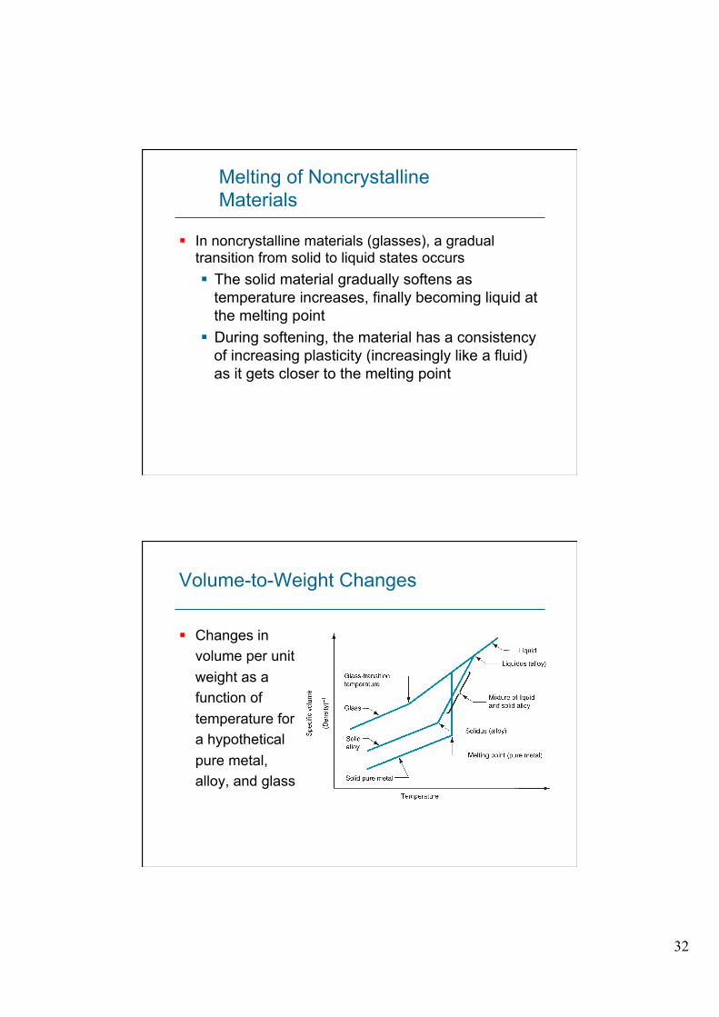
Volume-to-Weight Changes
§ Changes in volume per unit weight as a function of temperature for a hypothetical pure metal, alloy, and glass
33
Importance of Melting in Manufacturing
§ Metal casting - the metal is melted and then poured into a mold cavity
§ Metals with lower melting points are generally easier to cast
§ Plastic molding - melting characteristics of polymers are important in nearly all polymer shaping processes
§ Sintering of powdered metals - sintering does not melt the metal, but temperatures must approach the melting point to achieve bonding of the powders
Thermal Properties
§ Thermal expansion, melting, and heat of fusion are thermal properties because temperature determines the thermal energy level of the atoms, leading to the changes in materials
§ Additional thermal properties:
§ Specific heat
§ Thermal conductivity
§ These properties relate to the storage and flow of heat within a substance
34
Specific Heat
The quantity of heat energy required to increase the temperature of a unit mass of material by one degree
§ To determine the energy to heat a certain weight of metal to a given temperature: H = C W (T2 ‑ T1)
H = amount of heat energy;
C = specific heat of the material;
W = its weight; and
(T2 ‑ T1) = change in temperature
Volumetric Specific Heat
The quantity of heat energy required to raise the temperature of a unit volume of material by one degree
§ Density ρ multiplied by specific heat C
§ Volumetric specific heat = ρC
35
Thermal Conductivity
Capability of a material to transfer heat through itself by the physical mechanism of thermal conduction
§ Thermal conduction involves the transfer of thermal energy within a material from molecule to molecule by purely thermal motions
§ No mass transfer
§ Coefficient of thermal conductivity k is generally high in metals, low in ceramics and plastics § Units for k: J/s mm oC
Thermal Diffusivity
The ratio of thermal conductivity to volumetric specific heat is frequently encountered in heat transfer analysis
CkKρ
=

36
Thermal Properties in Manufacturing
§ Important in manufacturing because heat generation is common in so many processes
§ In some cases, heat is the energy that accomplishes the process § Heat treating, sintering of powder metals and
ceramics § In other cases, heat is generated as a result of the
process § Cold forming and machining of metals